
SCADAPack E Idec PLC Interface Manual · 6 SCADAPack E Idec PLC Interface Manual Remove tools,...
21
SCADAPack E Idec PLC Interface Manual
Transcript of SCADAPack E Idec PLC Interface Manual · 6 SCADAPack E Idec PLC Interface Manual Remove tools,...

SCADAPack E Idec PLCInterface Manual
SCADAPack E Idec PLC Interface Manual2
Table of Contents
Part I Idec PLC Interface 3
................................................................................................................................... 31 Technical Support
................................................................................................................................... 42 Safety Information
................................................................................................................................... 63 Preface
................................................................................................................................... 84 Overview
................................................................................................................................... 95 ISaGRAF I/O Board Interface
.......................................................................................................................................................... 10Input Boards 5.1
.......................................................................................................................................................... 13Output Boards 5.2
................................................................................................................................... 156 Communication Interface
................................................................................................................................... 167 Data Communications Protocol
................................................................................................................................... 178 System Points
.......................................................................................................................................................... 19Return Status Values & Data Cache Age 8.1
................................................................................................................................... 209 Diagnostics

Idec PLC Interface 3
I Idec PLC Interface
©2013 Control Microsystems Inc. All rights reserved.Printed in Canada.
Version: 8.05.4
The information provided in this documentation contains general descriptions and/or technicalcharacteristics of the performance of the products contained herein. This documentation isnot intended as a substitute for and is not to be used for determining suitability or reliability ofthese products for specific user applications. It is the duty of any such user or integrator toperform the appropriate and complete risk analysis, evaluation and testing of the productswith respect to the relevant specific application or use thereof. Neither Schneider Electric norany of its affiliates or subsidiaries shall be responsible or liable for misuse of the informationcontained herein. If you have any suggestions for improvements or amendments or havefound errors in this publication, please notify us.
No part of this document may be reproduced in any form or by any means, electronic ormechanical, including photocopying, without express written permission of SchneiderElectric.
All pertinent state, regional, and local safety regulations must be observed when installing andusing this product. For reasons of safety and to help ensure compliance with documentedsystem data, only the manufacturer should perform repairs to components.
When devices are used for applications with technical safety requirements, the relevantinstructions must be followed. Failure to use Schneider Electric software or approvedsoftware with our hardware products may result in injury, harm, or improper operating results.
Failure to observe this information can result in injury or equipment damage.
1 Technical Support
Support related to any part of this documentation can be directed to one of the followingsupport centers.

SCADAPack E Idec PLC Interface Manual4
Technical Support: The Americas
Available Monday to Friday 8:00am – 6:30pm Eastern Time
Toll free within North America 1-888-226-6876
Direct Worldwide +1-613-591-1943
Email [email protected]
Technical Support: Europe
Available Monday to Friday 8:30am – 5:30pm Central European Time
Direct Worldwide +31 (71) 597-1655
Email [email protected]
Technical Support: Asia
Available Monday to Friday 8:00am – 6:30pm Eastern Time (North America)
Direct Worldwide +1-613-591-1943
Email [email protected]
Technical Support: Australia
Inside Australia 1300 369 233
Email [email protected]
2 Safety Information
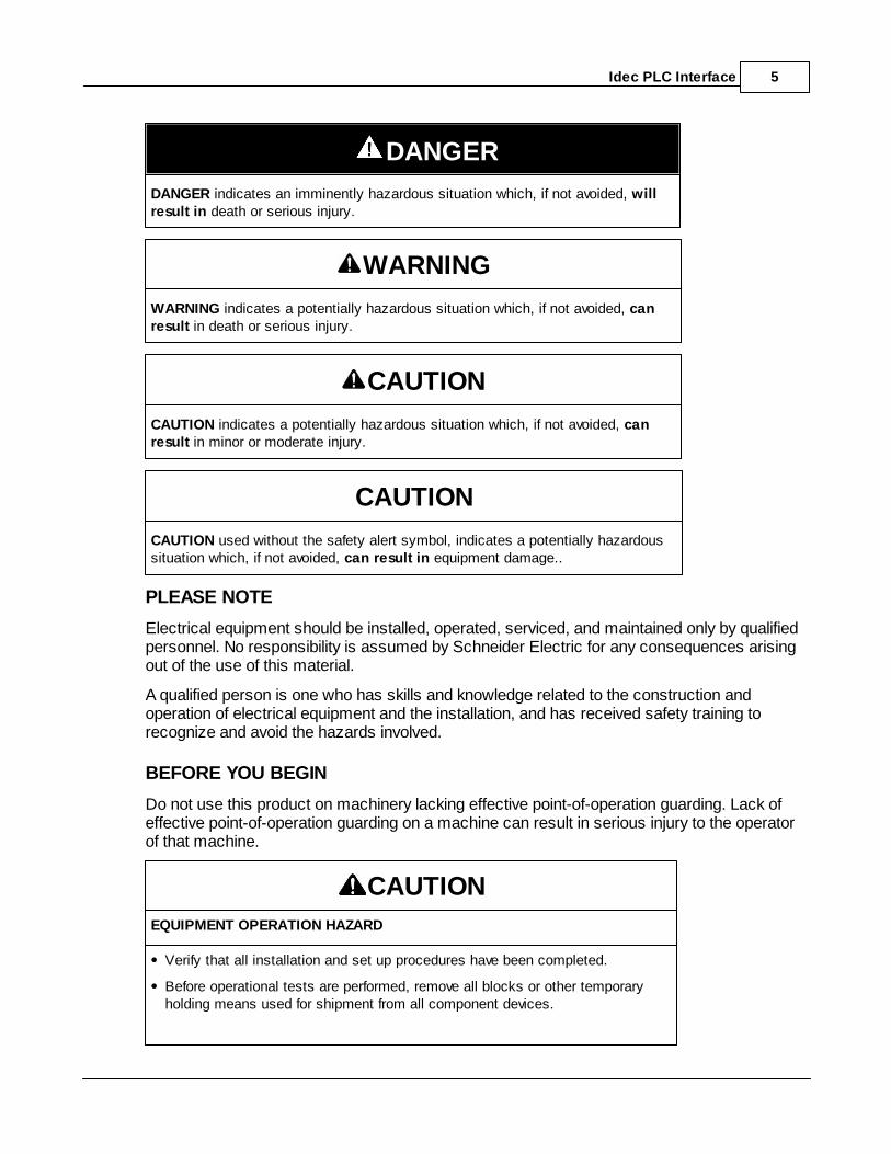
Read these instructions carefully, and look at the equipment to become familiar with thedevice before trying to install, operate, or maintain it. The following special messages mayappear throughout this documentation or on the equipment to warn of potential hazards or tocall attention to information that clarifies or simplifies a procedure.
The addition of this symbol to a Danger or Warning safety labelindicates that an electrical hazard exists, which will result in personalinjury if the instructions are not followed.
This is the safety alert symbol. It is used to alert you to potentialpersonal injury hazards. Obey all safety messages that follow thissymbol to avoid possible injury or death.
Idec PLC Interface 5
DANGER
DANGER indicates an imminently hazardous situation which, if not avoided, willresult in death or serious injury.
WARNING
WARNING indicates a potentially hazardous situation which, if not avoided, canresult in death or serious injury.
CAUTION
CAUTION indicates a potentially hazardous situation which, if not avoided, canresult in minor or moderate injury.
CAUTION
CAUTION used without the safety alert symbol, indicates a potentially hazardoussituation which, if not avoided, can result in equipment damage..
PLEASE NOTE
Electrical equipment should be installed, operated, serviced, and maintained only by qualifiedpersonnel. No responsibility is assumed by Schneider Electric for any consequences arisingout of the use of this material.
A qualified person is one who has skills and knowledge related to the construction andoperation of electrical equipment and the installation, and has received safety training torecognize and avoid the hazards involved.
BEFORE YOU BEGIN
Do not use this product on machinery lacking effective point-of-operation guarding. Lack ofeffective point-of-operation guarding on a machine can result in serious injury to the operatorof that machine.
CAUTION
EQUIPMENT OPERATION HAZARD
Verify that all installation and set up procedures have been completed.
Before operational tests are performed, remove all blocks or other temporaryholding means used for shipment from all component devices.
SCADAPack E Idec PLC Interface Manual6
Remove tools, meters, and debris from equipment.
Failure to follow these instructions can result in injury or equipmentdamage.
Follow all start-up tests recommended in the equipment documentation. Store all equipmentdocumentation for future references.
Software testing must be done in both simulated and real environments.
Verify that the completed system is free from all short circuits and grounds, except thosegrounds installed according to local regulations (according to the National Electrical Code inthe U.S.A, for instance). If high-potential voltage testing is necessary, followrecommendations in equipment documentation to prevent accidental equipment damage.
Before energizing equipment:
Remove tools, meters, and debris from equipment.
Close the equipment enclosure door.
Remove ground from incoming power lines.
Perform all start-up tests recommended by the manufacturer.
OPERATION AND ADJUSTMENTS
The following precautions are from the NEMA Standards Publication ICS 7.1-1995 (Englishversion prevails):
Regardless of the care exercised in the design and manufacture of equipment or in theselection and ratings of components, there are hazards that can be encountered if suchequipment is improperly operated.
It is sometimes possible to misadjust the equipment and thus produce unsatisfactory orunsafe operation. Always use the manufacturer’s instructions as a guide for functionaladjustments. Personnel who have access to these adjustments should be familiar with theequipment manufacturer’s instructions and the machinery used with the electricalequipment.
Only those operational adjustments actually required by the operator should be accessibleto the operator. Access to other controls should be restricted to prevent unauthorizedchanges in operating characteristics.
3 Preface
PurposeThe purpose of this document is to describe the Idec driver implementation for the Schneider ElectricSCADAPack E RTU.
Idec PLC Interface 7
Assumed KnowledgeFamiliarity with the ISaGRAF Workbench recommended.
Target AudienceSystems Engineers
Commissioning Engineers
Maintenance Technicians
ReferencesSCADAPack E ISaGRAF Technical Reference manual
ICS Triplex ISaGRAF Manuals
Idec IZUMI FA-1/FA-1J/FA-2/FA-2J Users Manual
SCADAPack E Idec PLC Interface Manual8
4 Overview
The Idec FA-2J PLC communicates with the SCADAPack E RTU using an ISaGRAF idecxxx I/O boardthrough an RTU serial port configured as a ‘PLC Device’.
The Idec registers are read and the return values cached in the RTU for access through an ISaGRAFinput board.
Outputs are written from the RTU’s output cache to the Idec PLC.
The SCADAPack E RTU’s handling of the communications is the same as other PLC drivercommunications.
The age and status of the data read from the Idec PLC is present in RTU system points that can beaccessed from within ISaGRAF, or external to the RTU.
The Idec Driver supports communications to the following Idec PLC’s:
FA-1 and FA-1J series (These PLCs don’t support expansion areas and data registers)
FA-2 and FA2J series
Idec PLC Interface 9
5 ISaGRAF I/O Board Interface
The idecxxx ISaGRAF I/O boards use a SCADAPack E RTU serial port configured as a ‘PLC Device’ tocommunicate with the Idec PLC.
Input Boards
Output Boards

SCADAPack E Idec PLC Interface Manual10
5.1 Input Boards
The Input boards supported by the Idec Driver are:
1 analog input
analog input
8 analog input
16 analog input
16 digital input
32 digital input
The analog input boards have the same basic layout as shown below.
The digital input boards have the same basic layout as shown below.
Idec PLC Interface 11
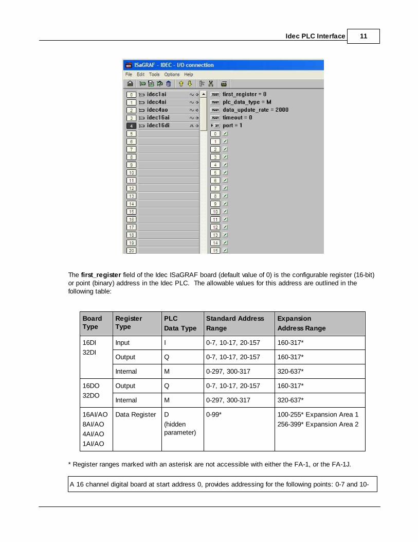
The first_register field of the Idec ISaGRAF board (default value of 0) is the configurable register (16-bit)or point (binary) address in the Idec PLC. The allowable values for this address are outlined in thefollowing table:
BoardType
RegisterType
PLC
Data Type
Standard Address
Range
Expansion
Address Range
16DI
32DI
Input I 0-7, 10-17, 20-157 160-317*
Output Q 0-7, 10-17, 20-157 160-317*
Internal M 0-297, 300-317 320-637*
16DO
32DO
Output Q 0-7, 10-17, 20-157 160-317*
Internal M 0-297, 300-317 320-637*
16AI/AO
8AI/AO
4AI/AO
1AI/AO
Data Register D
(hiddenparameter)
0-99* 100-255* Expansion Area 1
256-399* Expansion Area 2
* Register ranges marked with an asterisk are not accessible with either the FA-1, or the FA-1J.
A 16 channel digital board at start address 0, provides addressing for the following points: 0-7 and 10-
SCADAPack E Idec PLC Interface Manual12
17. Therefore the next consecutive board should be located at address 20 (not 16 or 18). Similarly forthe 32 digital point boards
The data_type field is a configurable value that determines what type of registers/points to access in thePLC. As shown in the table above, valid values for digital boards are: I for Input points, Q for Outputpoints, and M for internal points (default). The analog boards only allow access to Data Registers (valueof D) and for this reason the data_type field is hidden for these boards.
The data_update_rate field of the idecxxx ISaGRAF board (default 2000) is the configurable numberof seconds after which the RTU will request element array values from the Idec PLC. The SCADAPack ERTU will also request data from the Idec PLC constantly if the cache data age is greater than the data_update_rate. I.e. if communications are lost with the PLC, they are retried until thecommunications are restored.
The timeout field of the ISaGRAF board driver provides a parameter for specifying the communicationstimeout on an individual I/O board (i.e. the timeout applies to communications associated with thatboard). Where this value is “0”, the PLC device driver will use the default timeout (1200ms). Units for thisfield are in milliseconds.
The port field of the ISaGRAF board driver provides a parameter which defines which of the multiple RTU“PLC Device” ports will be used to communicate with the PLC or peripheral device. If only one “PLCDevice” port is configured, this field is ignored.

Idec PLC Interface 13
5.2 Output Boards
The Input boards supported by the Idec Driver are:
1 analog output
analog output
8 analog output
16 analog output
16 digital output
32 digital output
The analog output boards have the same basic layout as shown below.

SCADAPack E Idec PLC Interface Manual14
The digital output boards have the same basic layout as shown below.
These parameters are the same as described for the Input Boards.
The only difference is the must_write_rate. The unit for this parameter is the milliseconds, andspecifies the rate at which the data for the Output board is written to the PLC. Between “must_write_rate” periods, data is written to the PLC only when the ISaGRAF output variable values change. Individual I/Oboards may have different must write rates allowing prioritization of data sent to a PLC Device.
Idec PLC Interface 15
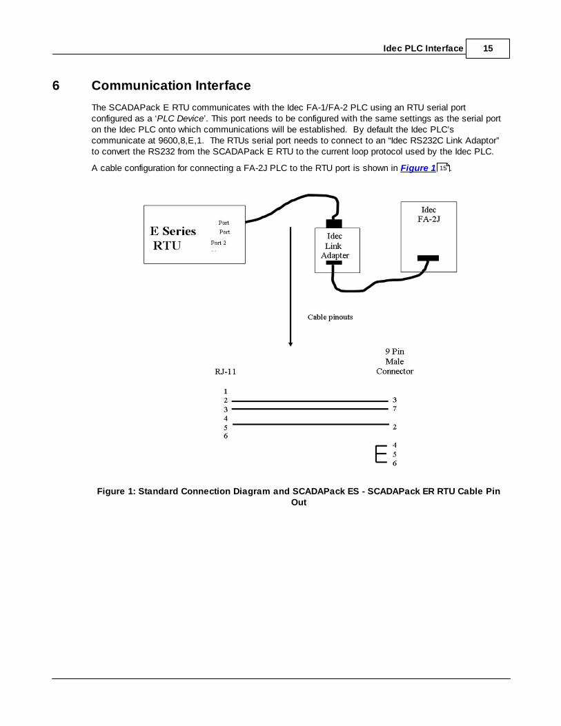
6 Communication Interface
The SCADAPack E RTU communicates with the Idec FA-1/FA-2 PLC using an RTU serial portconfigured as a ‘PLC Device’. This port needs to be configured with the same settings as the serial porton the Idec PLC onto which communications will be established. By default the Idec PLC’scommunicate at 9600,8,E,1. The RTUs serial port needs to connect to an “Idec RS232C Link Adaptor”to convert the RS232 from the SCADAPack E RTU to the current loop protocol used by the Idec PLC.
A cable configuration for connecting a FA-2J PLC to the RTU port is shown in Figure 1 .
Figure 1: Standard Connection Diagram and SCADAPack ES - SCADAPack ER RTU Cable PinOut
15
SCADAPack E Idec PLC Interface Manual16
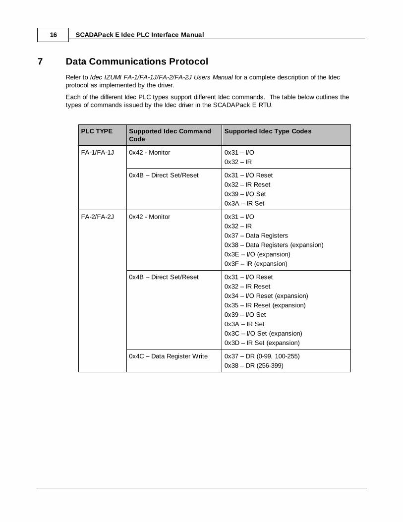
7 Data Communications Protocol
Refer to Idec IZUMI FA-1/FA-1J/FA-2/FA-2J Users Manual for a complete description of the Idecprotocol as implemented by the driver.
Each of the different Idec PLC types support different Idec commands. The table below outlines thetypes of commands issued by the Idec driver in the SCADAPack E RTU.
PLC TYPE Supported Idec CommandCode
Supported Idec Type Codes
FA-1/FA-1J 0x42 - Monitor 0x31 – I/O
0x32 – IR
0x4B – Direct Set/Reset 0x31 – I/O Reset
0x32 – IR Reset
0x39 – I/O Set
0x3A – IR Set
FA-2/FA-2J 0x42 - Monitor 0x31 – I/O
0x32 – IR
0x37 – Data Registers
0x38 – Data Registers (expansion)
0x3E – I/O (expansion)
0x3F – IR (expansion)
0x4B – Direct Set/Reset 0x31 – I/O Reset
0x32 – IR Reset
0x34 – I/O Reset (expansion)
0x35 – IR Reset (expansion)
0x39 – I/O Set
0x3A – IR Set
0x3C – I/O Set (expansion)
0x3D – IR Set (expansion)
0x4C – Data Register Write 0x37 – DR (0-99, 100-255)
0x38 – DR (256-399)
Idec PLC Interface 17
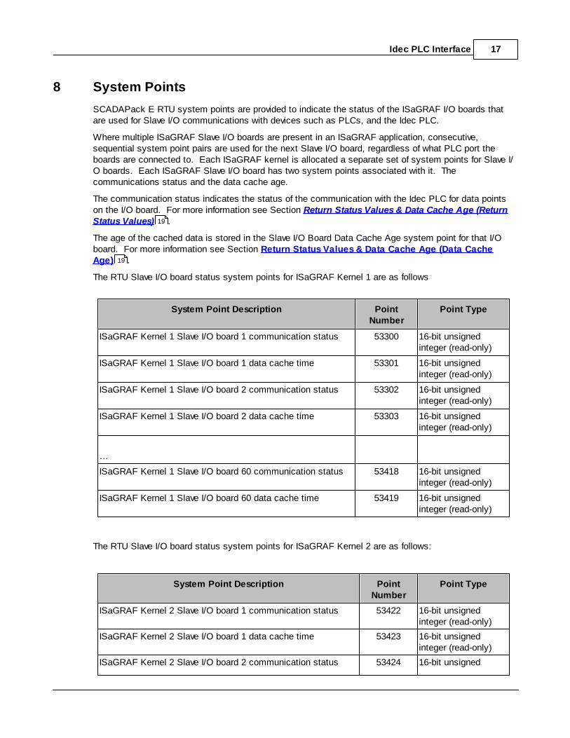
8 System Points
SCADAPack E RTU system points are provided to indicate the status of the ISaGRAF I/O boards thatare used for Slave I/O communications with devices such as PLCs, and the Idec PLC.
Where multiple ISaGRAF Slave I/O boards are present in an ISaGRAF application, consecutive,sequential system point pairs are used for the next Slave I/O board, regardless of what PLC port theboards are connected to. Each ISaGRAF kernel is allocated a separate set of system points for Slave I/O boards. Each ISaGRAF Slave I/O board has two system points associated with it. Thecommunications status and the data cache age.
The communication status indicates the status of the communication with the Idec PLC for data pointson the I/O board. For more information see Section Return Status Values & Data Cache Age (ReturnStatus Values) .
The age of the cached data is stored in the Slave I/O Board Data Cache Age system point for that I/Oboard. For more information see Section Return Status Values & Data Cache Age (Data CacheAge) .
The RTU Slave I/O board status system points for ISaGRAF Kernel 1 are as follows
System Point Description PointNumber
Point Type
ISaGRAF Kernel 1 Slave I/O board 1 communication status 53300 16-bit unsignedinteger (read-only)
ISaGRAF Kernel 1 Slave I/O board 1 data cache time 53301 16-bit unsignedinteger (read-only)
ISaGRAF Kernel 1 Slave I/O board 2 communication status 53302 16-bit unsignedinteger (read-only)
ISaGRAF Kernel 1 Slave I/O board 2 data cache time 53303 16-bit unsignedinteger (read-only)
…
ISaGRAF Kernel 1 Slave I/O board 60 communication status 53418 16-bit unsignedinteger (read-only)
ISaGRAF Kernel 1 Slave I/O board 60 data cache time 53419 16-bit unsignedinteger (read-only)
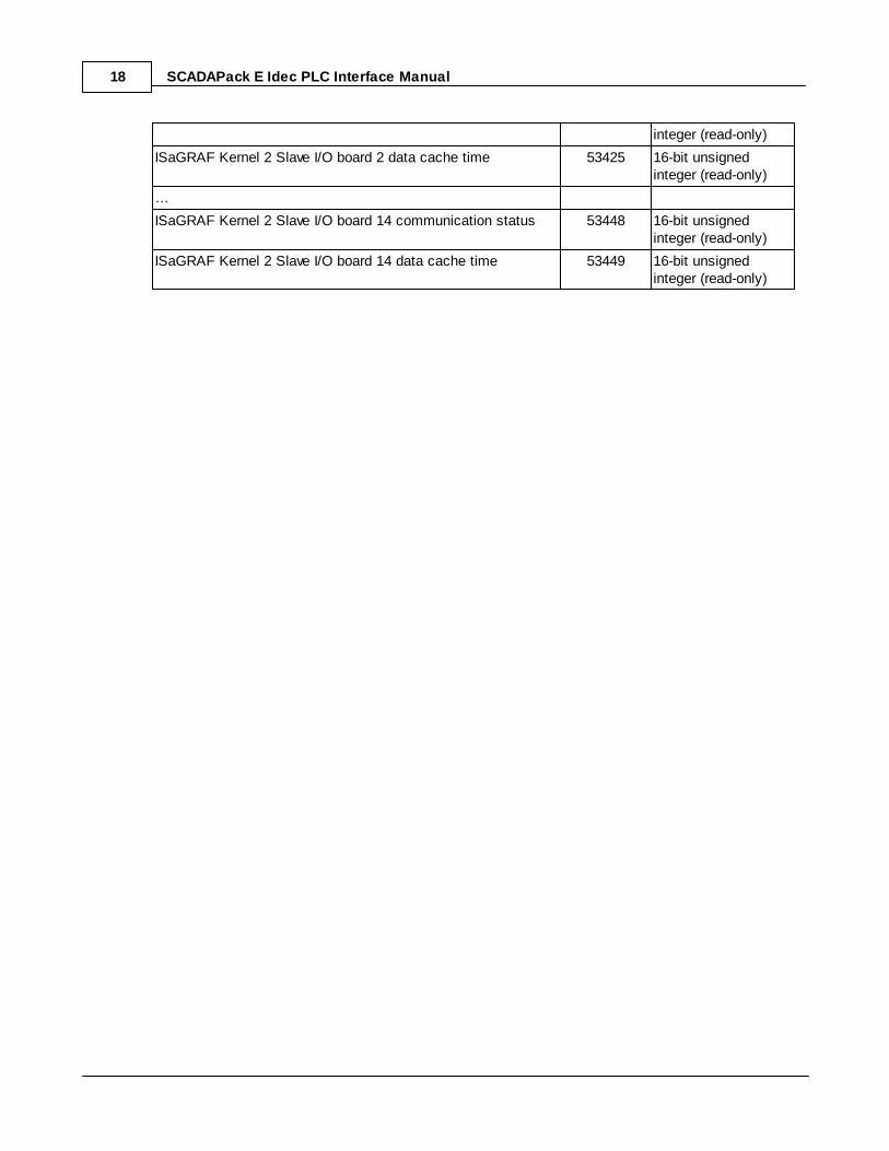
The RTU Slave I/O board status system points for ISaGRAF Kernel 2 are as follows:
System Point Description PointNumber
Point Type
ISaGRAF Kernel 2 Slave I/O board 1 communication status 53422 16-bit unsignedinteger (read-only)
ISaGRAF Kernel 2 Slave I/O board 1 data cache time 53423 16-bit unsignedinteger (read-only)
ISaGRAF Kernel 2 Slave I/O board 2 communication status 53424 16-bit unsigned
19
19
SCADAPack E Idec PLC Interface Manual18
integer (read-only)
ISaGRAF Kernel 2 Slave I/O board 2 data cache time 53425 16-bit unsignedinteger (read-only)
…
ISaGRAF Kernel 2 Slave I/O board 14 communication status 53448 16-bit unsignedinteger (read-only)
ISaGRAF Kernel 2 Slave I/O board 14 data cache time 53449 16-bit unsignedinteger (read-only)
Idec PLC Interface 19
8.1 Return Status Values & Data Cache Age
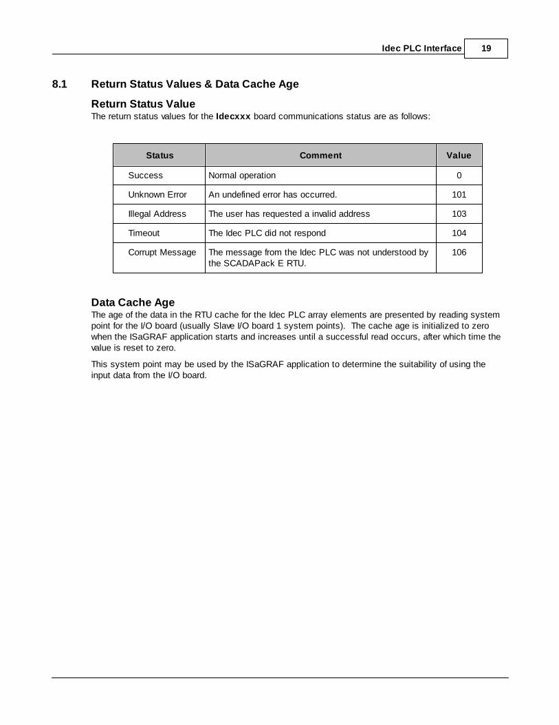
Return Status ValueThe return status values for the Idecxxx board communications status are as follows:
Status Comment Value
Success Normal operation 0
Unknown Error An undefined error has occurred. 101
Illegal Address The user has requested a invalid address 103
Timeout The Idec PLC did not respond 104
Corrupt Message The message from the Idec PLC was not understood bythe SCADAPack E RTU.
106
Data Cache AgeThe age of the data in the RTU cache for the Idec PLC array elements are presented by reading systempoint for the I/O board (usually Slave I/O board 1 system points). The cache age is initialized to zerowhen the ISaGRAF application starts and increases until a successful read occurs, after which time thevalue is reset to zero.
This system point may be used by the ISaGRAF application to determine the suitability of using theinput data from the I/O board.

SCADAPack E Idec PLC Interface Manual20
9 Diagnostics
The SCADAPack E RTU indicates configuration or communication diagnostics via Diagnostic Displaymode from a Command line session.
Configuration diagnostics are indicated via ISaGRAF I/O board messages and are displayed when inDiagnostic Display mode (use DIAG command at command prompt).
Communication diagnostics for the Idec PLC are enabled when the following commands are entered atthe SCADAPack E RTU command prompt:
PLCDIAG ENABLE *DIAG

Idec PLC Interface 21