SCADAPack 333E Hardware Manual - · PDF fileSCADAPack 333E Hardware Manual 7 Remove tools,...
83
SCADAPack 333E Hardware Manual
Transcript of SCADAPack 333E Hardware Manual - · PDF fileSCADAPack 333E Hardware Manual 7 Remove tools,...

SCADAPack 333E HardwareManual

SCADAPack 333E Hardware Manual2
Table of Contents
Part I SCADAPack 333E Hardware Manual 4
................................................................................................................................... 41 Technical Support
................................................................................................................................... 52 Safety Information
................................................................................................................................... 83 Introduction
................................................................................................................................... 104 Installation
.......................................................................................................................................................... 11Field Wiring 4.1
................................................................................................................................... 135 Power Supply Overview & Requirements
.......................................................................................................................................................... 14Sample Power Calculations 5.1
.......................................................................................................................................................... 15Power Management Features 5.2......................................................................................................................................................... 17COM1 and COM2 Serial Port Pow er Control5.2.1......................................................................................................................................................... 18COM3 Serial Port Pow er Control5.2.2
................................................................................................................................... 196 Internal Analog Points
................................................................................................................................... 207 Internal Binary Points
................................................................................................................................... 218 Counter Inputs
.......................................................................................................................................................... 22Counter Input 0 8.1
.......................................................................................................................................................... 23Turbine Meter Counter Inputs 1 and 2 8.2......................................................................................................................................................... 24Directly Connecting to Low Voltage Turbine Meters8.2.1......................................................................................................................................................... 25Connecting to Open Collector Outputs w ith Internal Pullup8.2.2......................................................................................................................................................... 27Connecting to Open Collector Outputs w ith External Pullup8.2.3
................................................................................................................................... 289 Serial Communication
.......................................................................................................................................................... 29RS-232 Serial Communications Ports 9.1......................................................................................................................................................... 32COM1 and COM2 RS-232 Serial Port9.1.1......................................................................................................................................................... 34COM3 RS-232 Serial Port9.1.2......................................................................................................................................................... 36RS-232 Wiring Examples9.1.3......................................................................................................................................................... 39RS-232 Cables9.1.4.......................................................................................................................................................... 41RS-485 Serial Communication Ports 9.2......................................................................................................................................................... 42COM1 and COM2 RS-485 Serial Port9.2.1......................................................................................................................................................... 45RS-485 Bias & Termination Resistors9.2.2......................................................................................................................................................... 47RS-485 Wiring Examples9.2.3
................................................................................................................................... 4810 Ethernet Communication
.......................................................................................................................................................... 49LAN Port Settings 10.1......................................................................................................................................................... 50TCP/IP Settings10.1.1......................................................................................................................................................... 51Modbus/TCP Settings10.1.2......................................................................................................................................................... 53Modbus RTU in TCP Settings10.1.3.......................................................................................................................................................... 54RJ-45 Modular Connector for Ethernet 10.2
................................................................................................................................... 5511 USB Ports & Connections
.......................................................................................................................................................... 56Peripheral & Host Port 11.1
................................................................................................................................... 5812 Operation
.......................................................................................................................................................... 59Operating Modes 12.1......................................................................................................................................................... 60Run Mode12.1.1......................................................................................................................................................... 61Service Mode12.1.2......................................................................................................................................................... 62Cold Boot Mode12.1.3......................................................................................................................................................... 64Factory Boot Mode12.1.4
3Contents
3
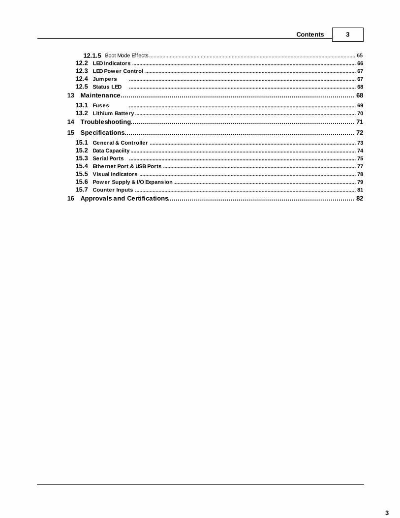
......................................................................................................................................................... 65Boot Mode Effects12.1.5.......................................................................................................................................................... 66LED Indicators 12.2.......................................................................................................................................................... 67LED Power Control 12.3.......................................................................................................................................................... 67Jumpers 12.4.......................................................................................................................................................... 68Status LED 12.5
................................................................................................................................... 6813 Maintenance
.......................................................................................................................................................... 69Fuses 13.1
.......................................................................................................................................................... 70Lithium Battery 13.2
................................................................................................................................... 7114 Troubleshooting
................................................................................................................................... 7215 Specifications
.......................................................................................................................................................... 73General & Controller 15.1
.......................................................................................................................................................... 74Data Capaciity 15.2
.......................................................................................................................................................... 75Serial Ports 15.3
.......................................................................................................................................................... 77Ethernet Port & USB Ports 15.4
.......................................................................................................................................................... 78Visual Indicators 15.5
.......................................................................................................................................................... 79Power Supply & I/O Expansion 15.6
.......................................................................................................................................................... 81Counter Inputs 15.7
................................................................................................................................... 8216 Approvals and Certifications

SCADAPack 333E Hardware Manual4
I SCADAPack 333E Hardware Manual
©2013 Control Microsystems Inc. All rights reserved.Printed in Canada.
Version: 8.05.4
The information provided in this documentation contains general descriptions and/or technicalcharacteristics of the performance of the products contained herein. This documentation isnot intended as a substitute for and is not to be used for determining suitability or reliability ofthese products for specific user applications. It is the duty of any such user or integrator toperform the appropriate and complete risk analysis, evaluation and testing of the productswith respect to the relevant specific application or use thereof. Neither Schneider Electric norany of its affiliates or subsidiaries shall be responsible or liable for misuse of the informationcontained herein. If you have any suggestions for improvements or amendments or havefound errors in this publication, please notify us.
No part of this document may be reproduced in any form or by any means, electronic ormechanical, including photocopying, without express written permission of SchneiderElectric.
All pertinent state, regional, and local safety regulations must be observed when installing andusing this product. For reasons of safety and to help ensure compliance with documentedsystem data, only the manufacturer should perform repairs to components.
When devices are used for applications with technical safety requirements, the relevantinstructions must be followed. Failure to use Schneider Electric software or approvedsoftware with our hardware products may result in injury, harm, or improper operating results.
Failure to observe this information can result in injury or equipment damage.
1 Technical Support
Support related to any part of this documentation can be directed to one of the followingsupport centers.

SCADAPack 333E Hardware Manual 5
Technical Support: The Americas
Available Monday to Friday 8:00am – 6:30pm Eastern Time
Toll free within North America 1-888-226-6876
Direct Worldwide +1-613-591-1943
Email [email protected]
Technical Support: Europe
Available Monday to Friday 8:30am – 5:30pm Central European Time
Direct Worldwide +31 (71) 597-1655
Email [email protected]
Technical Support: Asia
Available Monday to Friday 8:00am – 6:30pm Eastern Time (North America)
Direct Worldwide +1-613-591-1943
Email [email protected]
Technical Support: Australia
Inside Australia 1300 369 233
Email [email protected]
2 Safety Information
Read these instructions carefully, and look at the equipment to become familiar with thedevice before trying to install, operate, or maintain it. The following special messages mayappear throughout this documentation or on the equipment to warn of potential hazards or tocall attention to information that clarifies or simplifies a procedure.
The addition of this symbol to a Danger or Warning safety labelindicates that an electrical hazard exists, which will result in personalinjury if the instructions are not followed.
This is the safety alert symbol. It is used to alert you to potentialpersonal injury hazards. Obey all safety messages that follow thissymbol to avoid possible injury or death.

SCADAPack 333E Hardware Manual6
DANGER
DANGER indicates an imminently hazardous situation which, if not avoided, willresult in death or serious injury.
WARNING
WARNING indicates a potentially hazardous situation which, if not avoided, canresult in death or serious injury.
CAUTION
CAUTION indicates a potentially hazardous situation which, if not avoided, canresult in minor or moderate injury.
CAUTION
CAUTION used without the safety alert symbol, indicates a potentially hazardoussituation which, if not avoided, can result in equipment damage..
PLEASE NOTE
Electrical equipment should be installed, operated, serviced, and maintained only by qualifiedpersonnel. No responsibility is assumed by Schneider Electric for any consequences arisingout of the use of this material.
A qualified person is one who has skills and knowledge related to the construction andoperation of electrical equipment and the installation, and has received safety training torecognize and avoid the hazards involved.
BEFORE YOU BEGIN
Do not use this product on machinery lacking effective point-of-operation guarding. Lack ofeffective point-of-operation guarding on a machine can result in serious injury to the operatorof that machine.
CAUTION
EQUIPMENT OPERATION HAZARD
Verify that all installation and set up procedures have been completed.
Before operational tests are performed, remove all blocks or other temporaryholding means used for shipment from all component devices.

SCADAPack 333E Hardware Manual 7
Remove tools, meters, and debris from equipment.
Failure to follow these instructions can result in injury or equipmentdamage.
Follow all start-up tests recommended in the equipment documentation. Store all equipmentdocumentation for future references.
Software testing must be done in both simulated and real environments.
Verify that the completed system is free from all short circuits and grounds, except thosegrounds installed according to local regulations (according to the National Electrical Code inthe U.S.A, for instance). If high-potential voltage testing is necessary, followrecommendations in equipment documentation to prevent accidental equipment damage.
Before energizing equipment:
Remove tools, meters, and debris from equipment.
Close the equipment enclosure door.
Remove ground from incoming power lines.
Perform all start-up tests recommended by the manufacturer.
OPERATION AND ADJUSTMENTS
The following precautions are from the NEMA Standards Publication ICS 7.1-1995 (Englishversion prevails):
Regardless of the care exercised in the design and manufacture of equipment or in theselection and ratings of components, there are hazards that can be encountered if suchequipment is improperly operated.
It is sometimes possible to misadjust the equipment and thus produce unsatisfactory orunsafe operation. Always use the manufacturer’s instructions as a guide for functionaladjustments. Personnel who have access to these adjustments should be familiar with theequipment manufacturer’s instructions and the machinery used with the electricalequipment.
Only those operational adjustments actually required by the operator should be accessibleto the operator. Access to other controls should be restricted to prevent unauthorizedchanges in operating characteristics.

SCADAPack 333E Hardware Manual8
3 Introduction
Figure 4.1: The SCADAPack 333E
The SCADAPack 333E is an intelligent microprocessor based telemetry and control unit. TheSCADAPack 333E may operate Stand-alone providing data acquisition, process control and telemetryfunctions, or in conjunction with other SCADAPack E RTUs, I/O modules, and peripherals such asPLC’s. The SCADAPack 333E features extensive communications capabilities including Ethernet andUSB interfaces and a powerful embedded micro-controller to provide the user with a sophisticatedtelemetry Remote Terminal Unit (RTU) in an Open Systems environment.
Many operational facilities can be configured, depending on the required telemetry and controlapplication. This manual describes the hardware aspects of the SCADAPack 333E.
The SCADAPack 333E on-board switch mode power supply allows a wide range of voltage operationfrom a single external voltage supply (11 – 30 Vdc).
The use of FLASH memory chips allows new firmware to be downloaded both locally and remotely viathe interfaces of the SCADAPack 333E, without removing the SCADAPack 333E from its enclosure, or

SCADAPack 333E Hardware Manual 9
removing the lid.
SCADAPack 333E configurations are maintained in the on-board battery backed RAM and may bemodified locally or remotely.
The SCADAPack 333E is integrated with a lower I/O module known as the 5611. See the SCADAPackE 5611 Hardware Manual for more information.

SCADAPack 333E Hardware Manual10
4 Installation
The installation of SCADAPack E Smart RTUs requires mounting the controller on the 7.5mm by 35mmDIN rail and optionally connecting the SCADAPack E Smart RTU to a system I/O Bus.
5611 Input/Output ModuleThe SCADAPack 333E is a SCADAPack E Smart RTU with an integrated 5611 lower I/O module. TheModel 5611 Input Output Module adds four (4) analog inputs, 16 digital inputs, 10 relay digital outputsand two (2) optional analog output channels to the 5000 Series input/output system.
Refer to the SCADAPack E 5611 Input / Output (I/O) hardware manual for details on wiring, configuringand operation.

SCADAPack 333E Hardware Manual 11
4.1 Field Wiring
SCADAPack E Smart RTUs use screw termination style connectors for termination of field wiring. Theseconnectors accommodate solid or stranded wires from 12 to 22 AWG. The connectors are removableallowing replacement of the SCADAPack Controller without disturbing the field wiring. Leave enoughslack in the field wiring for the connector to be removed.
CAUTION
UNEXPECTED EQUIPMENT OPERATION
Do not exceed the maximum voltage specified for each analog and digital input.
Failure to follow these instructions can result in equipmentdamage.
WARNINGHAZARD OF ELECTRIC SHOCK
Remove power from all devices before connecting or disconnecting inputs oroutputs to any terminal or installing or removing any hardware.
Failure to follow these instructions can result in death, seriousinjury or equipment damage.
To remove the termination connector:
Pull the connector upward from the board. Apply even pressure to both ends of the connector.
To install the termination connector:
Line up the pins on the module with the holes in the connector.
Push the connector onto the pins. Apply even pressure to both ends on the connector.
There are seven connectors for field wiring. Refer to Figure 5.1: SCADAPack 333E Board Layout for connector locations.
The three RS-232 communication ports, COM 1, COM 2 and COM 3, connect to 8 pin modularjacks. Refer to Section RS-232 Serial Communications Ports for pinout details and wiringdiagrams for these modular jacks.
One Ethernet port connects to an 8 pin modular jack. Refer to Section Ethernet Communication for pinout details.
The counter input wiring terminates in removable terminal connectors. Connector pinouts and wiringexamples are described in sections of this manual.
The USB ports use conventional USB-A and USB-B interface connectors. Refer to Section USBPorts for details.
12
12
29
48
55

SCADAPack 333E Hardware Manual12
Figure 5.1: SCADAPack 333E Board Layout

SCADAPack 333E Hardware Manual 13
5 Power Supply Overview & Requirements
The SCADAPack 333E is powered from an 11V DC to 30V DC input power source.
Input power is applied to the positive (+) and negative (-) terminals on connector P3.
Refer to Section Specifications of this manual for the minimum and maximum operating voltagesand input power requirements.
When the input voltage is below the minimum recommended voltage the SCADAPack 333E will turnoff.
Exceeding the maximum input voltage or applying a reverse voltage will blow the input power fuse.
Unlike some other members of the SCADAPack family, the SCADAPack 333E operates only on a DCpower sources. Connections to power sources such as 16Vac transformers will blow the fuse and maycause damage to the SCADAPack 333E.
The DC power-input voltage is used to generate 5V at 1.2A (6W) some of which is used for the controlleronboard circuitry. The output capacity of the 6W is sufficient to power the SCADAPack 333E controllerboard, a SCADAPack Vision operator interface with a limited number of 5000 Series I/O modules, suchas the 5611 I/O Module integrated in to the SCADAPack 333E.
The power available for any 5000 Series expansion I/O modules is limited to 5.5W (5V at 1200mA) anddepends on the controller features enabled.
System GroundingIn many applications, it is desirable to ground the system by connecting the system power supplycommon, to the chassis or panel ground. The negative (–ve) side of the DC power input terminal as wellas I/O point terminals labeled GND are connected to chassis ground.
72

SCADAPack 333E Hardware Manual14
5.1 Sample Power Calculations
Example 1: Assume we have a 5210 controller board with an integrated 5611 I/O module(SCADAPack 333E).
In this example it is assumed that the controller is powered from a 24V supply. the 4 Analog Inputs andboth analog outputs are in use on the 5611. The controller will not be running in a reduced power mode.
The current requirement of the controller board and I/O module is summarized in the table below.
Table 6.1: Sample Power Calculations (Example 1)
5V Current 24V Current
5210 Controller Board(base current in normalmode)
85mA
LAN Port 135mA
USB 35mA
LEDs 100mA
5611 I/O Module 235mA 10.3mA + 10 x 20mA = 211mA
Total 590mA
Available for I/O expansionand COM/Visions
610mA
remaining from1.2A capacity
In this case, 610mA at 5V power is available for any I/O expansion, and for COM/Vision power.
In this example, the total input power required from a 24V power supply is calculated as follows:
5V Power: 5V x .59A = 2.95W
Total Input Power Required = 2.95W/0.85 = 3.47W (assuming 85% power supply efficiency).
Therefore your 24V power supply needs to be capable of providing 3.47W/12 = 0.145A plus 0.211A forthe 10 x 20mA current loops and the analog section of the 5611 for a total of 0.356A.

SCADAPack 333E Hardware Manual 15
5.2 Power Management Features
The SCADAPack 333E provides a number of special features to reduce power consumption. Refer to Figure 6.1: Power Management for an overview of the power management features.
These power management features are:
COM1 and COM2 power control
COM3 serial port power control for Vision Display
LED Power control
Figure 6.1: Power Management
System binary points and the power management functions they control are described in the followingsections.
SCADAPack E Configurator controls for the power management modes are presented on the General /Controller Settings page.
15
17
18
SCADAPack 333E Hardware Manual16

SCADAPack 333E Hardware Manual 17
5.2.1 COM1 and COM2 Serial Port Power Control
Serial ports on the SCADAPack 333E can have pin 1 on the RJ-45 connector connected to 5V. ForCOM1 and COM2 connectors, this pin can be connected to the 5V power supply by installing a jumperat J7 (5V COM1,COM2). Refer to COM3 Serial Port Power Control to enable 5V on COM3.
This 5V output is used to power Vision terminals and other SchneiderElectric accessories. Check that cables connecting this pin have no voltages applied..
18

SCADAPack 333E Hardware Manual18
5.2.2 COM3 Serial Port Power Control
The COM3 serial port is for use with the SCADAPack Vision or other Human Machine Interface (HMI).Pin 1 of the RJ-45 connector provides a switched 5-volt power for the SCADAPack Vision or other HMI.
Refer to Section COM3 RS-232 Serial Port for information on COM3 and Section RS-232 Cables(RJ-45 to SCADAPack Vision) for wiring examples.
Also see LED Power Control .
HMI power is controlled in the following ways.
When the LED power is enabled, the HMI power is turned on.
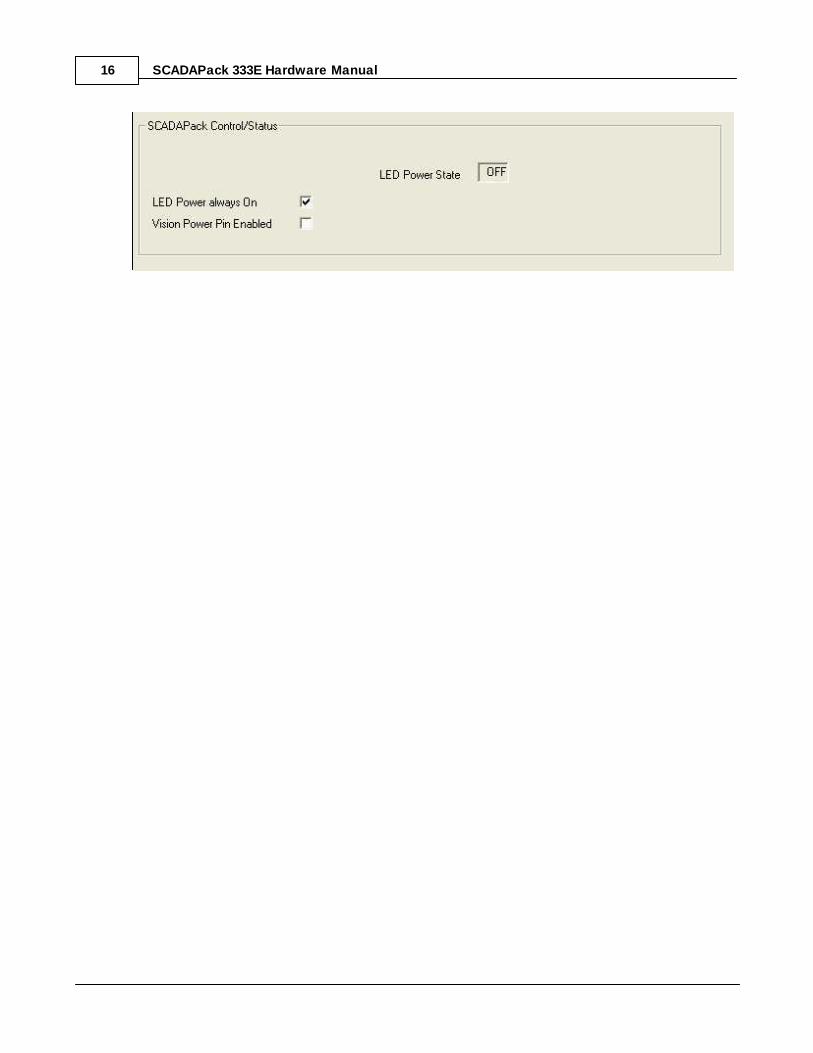
When the LED power is disabled and system Digital Output 50750 is ON (SCADAPack EConfigurator Vision Power Pin Enabled ON) HMI power is turned on.
When the LED power is disabled and system Digital Output 50750 is OFF (SCADAPack EConfigurator Vision Power Pin Enabled OFF) HMI power is turned off.
System Digital Input 50750 indicates the status of COM3 serial port power. Digital Input 50750 is setwhen COM3 serial port power is on and is cleared when COM3 serial port power is off.
HMI power is turned on whenever the LED power is enabled. This feature is provided for service anddiagnostics. Refer to Section LED Power Control for further information on this feature.
The Vision Power Pin Enable control in the SCADAPack E Configurator Control Modes property page,located in the General folder, can also be used to control the Vision (or other HMI) power.
34
39
67
67

SCADAPack 333E Hardware Manual 19
6 Internal Analog Points
Internal analog points measure RTU input Supply voltage and the controller's ambient temperature.These can be accessed from a user application program or via remote RTU communications.
Supply voltage
System Analog point 50060
The input supply voltage measures the incoming power supply. It is useful for measuring the operatingenvironment of the controller and returns a floating point value in the range 0 - 32.767V.
Use the system point directly by assigning a point of this point number (50060) in the RTU database
or, Read the system point into a user ISaGRAF application from an Input Board connection
Internal temperature
Internal Temperature oC
System Analog Point 50062
This analog system point measures the ambient temperature at the controller circuit board in degreesCelsius. It is useful for measuring the operating environment of the controller and returns an integer valuein the range –40 to 75.
The temperature reading represents temperatures in the range –40°C to 75°C. Temperatures outside thisrange cannot be measured.
Use the system point directly by assigning an analog point of this point number (50062) in the RTUdatabase
Read the system point into a user ISaGRAF application as an Integer or Real variable from an InputBoard connection
Internal Temperature oF
System Analog Point 50063
This analog system point measures the ambient temperature at the controller circuit board in degreesFahrenheit. It is useful for measuring the operating environment of the controller and returns an integervalue in the range –40 to 167.
The temperature reading represents temperatures in the range –40°C to 167°F. Temperatures outsidethis range cannot be measured.
Use the system point directly by assigning an analog point at this point number (50063) in the RTUdatabase
Read the system point into a user ISaGRAF application as an Integer or Real variable from an inputboard

SCADAPack 333E Hardware Manual20
7 Internal Binary Points
Internal system binary points are provided which indicate the status such as the RTU input Supplyvoltage and the controller's on-board lithium battery. These can be accessed from a user applicationprogram or via remote RTU communications.
Local Input Power Supply LowBinary System Point 50206An internal binary point indicates the condition of the input power supply. It compares the SupplyVoltage System Analog Point 50060 with the Low Voltage Alarm Level set in SCADAPack E Configurator General / Control Modes page. If the inputpower supply is lower than the Low Voltage Alarm Level then this Binary System Point is activated.
Use the system point directly by assigning a binary point to this point number (50206) in the RTUdatabase
For ISaGRAF applications, read the status point through an Input Board connection.
Local On Board Battery LowBinary System Point 50207
An internal binary point indicates the condition of a monitor on the lithium battery that maintains the non-volatile RAM in the controller. If active, the point indicates that the on-board controller battery needs replacement.
Use the system point directly by assigning a binary point to this point number (50207) in the RTUdatabase
For ISaGRAF applications, read the status point through an Input Board connection.
COM3 Serial Port Power ControlBinary System Point 50750
See COM3 Serial Port Power Control .18

SCADAPack 333E Hardware Manual 21
8 Counter Inputs
The SCADAPack 333E has three counter inputs, identified as Counter 0, 1 and 2.
Two of the counter inputs, Counter 1 and 2, are designed for millivolt level turbine meters.
The third, Counter 0, is a high level digital input for use with open collector/drain output amplifiers.
CAUTION
UNEXPECTED EQUIPMENT OPERATION
Do not exceed the maximum voltage specified for each counter input.
Failure to follow these instructions can result in equipmentdamage.
Refer to the appropriate software manual for information on using the SCADAPack 333E Counter Inputsin application programs.
o Assign RTU database point indexes to the Counter In field(s) using the 5210 I/O Module in
SCADAPack E Configurator's I/O / SCADAPack I/O page.
o For ISaGRAF applications use an rtuXXctr Input Board or complex equipment type for the
SCADAPack 333E to read the controller board counters.
o Use the Counter Input point directly by using a Counter Point in the RTU database for the
assigned DNP Point Number
Counter Input 0
Turbine Meter Counter Inputs 1 and 2
22
23
SCADAPack 333E Hardware Manual22
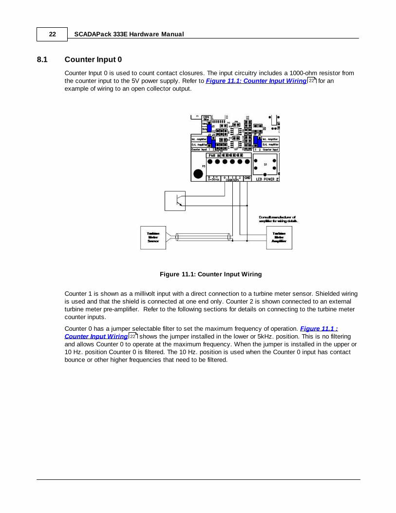
8.1 Counter Input 0
Counter Input 0 is used to count contact closures. The input circuitry includes a 1000-ohm resistor fromthe counter input to the 5V power supply. Refer to Figure 11.1: Counter Input Wiring for anexample of wiring to an open collector output.
Figure 11.1: Counter Input Wiring
Counter 1 is shown as a millivolt input with a direct connection to a turbine meter sensor. Shielded wiringis used and that the shield is connected at one end only. Counter 2 is shown connected to an externalturbine meter pre-amplifier. Refer to the following sections for details on connecting to the turbine metercounter inputs.
Counter 0 has a jumper selectable filter to set the maximum frequency of operation. Figure 11.1 :Counter Input Wiring shows the jumper installed in the lower or 5kHz. position. This is no filteringand allows Counter 0 to operate at the maximum frequency. When the jumper is installed in the upper or10 Hz. position Counter 0 is filtered. The 10 Hz. position is used when the Counter 0 input has contactbounce or other higher frequencies that need to be filtered.
22
22

SCADAPack 333E Hardware Manual 23
8.2 Turbine Meter Counter Inputs 1 and 2
The SCADAPack 333E allows for the direct connection of two turbine meter sensors. These sensorsproduce millivolt outputs and and require no connection to an additional pre-amplifier when connecting toa SCADAPack 333E. The turbine meter inputs should be used in low noise environments with shieldedcabling.
There are four jumper links positions: J3, J4, J5 and J6, associated with configuring the turbine metercounter inputs for either millivolt signals (direct to sensor) or high level signals from turbine meters withexternal amplifiers, dry contacts or open collector outputs.
Jumper positions J3 and J5 enable the SCADAPack’s pre-amplifier on turbine counter input 1. JumpersJ4 and J6 enable the SCADAPack E Smart RTU pre-amplifier on turbine counter input 2.
Directly Connecting to Low Voltage Turbine Meters
Connecting to Higher Voltage Turbine Meters
Connecting to Open Collector / Dry Contact Turbine Meters
24
27
25

SCADAPack 333E Hardware Manual24
8.2.1 Directly Connecting to Low Voltage Turbine Meters
When connecting a low voltage (millivolt) turbine meter directly to counter input 1, enable theSCADAPack 333E internal pre-amplifier on this input as follows:
1. Install jumper J11 on the ‘Int Amplifier’ position.
2. Install jumper J9 on the ‘See J11’ position, as shown below.
Figure 11.2: Setting Jumpers on Counter Input 1 for Low Voltage Turbine Meters
Similarly, when connecting a low voltage (millivolt) turbine meter directly to the counter input 2,
3. Install jumper J6 on the ‘Int Amplifier’ position.
4. Install jumper J4 on the ‘See J12’ position, as shown below.
Figure 11.3: Setting Jumpers on Counter Input 2 for Low Voltage Turbine Meters

SCADAPack 333E Hardware Manual 25
8.2.2 Connecting to Open Collector Outputs with Internal Pullup
Counter Inputs 1 and 2 can also used with open collector outputs. In this configuration, the SCADAPackinternal amplifiers need to be bypassed. There are 1000 ohm pull-up resistors connected to the inputpower supply.
This described above can only be used if the SCADAPack 333E is powered from 12V.
For Counter 1:
1. Install jumper J5 in the ‘Ext Amplifier' Position.
2. Install jumper J3 in the ‘Ext Amplifier' Position.
For Counter 2
3. Install jumper J6 in the ‘Ext Amplifier' Position.
4. Install jumper J4 in the ‘Ext Amplifier' Position.
Your application may have a specific current requirement as specified by the manufacturer. As shown inthe figure above, the SCADAPack 333E includes a 1000-ohm resistor from the counter input to the DCinput power source, when the jumpers J3 and J5 are installed in the ‘Ext Amplifier’ position, as describedabove. The above configuration is the recommended wiring for a Halliburton Low Power Pre-Amp, whenthe SCADAPack 333E is powered from 12V.

SCADAPack 333E Hardware Manual26
Figure 11.5: Setting Counter Inputs 1 and 2 for Open Collector outputs with Internal Pullup
The above configuration applies only when the controller is being powered using 12V.

SCADAPack 333E Hardware Manual 27
8.2.3 Connecting to Open Collector Outputs with External Pullup
In applications that requires a pull-up resistor different than 1000 ohms, jumper J5 and J6 should not beinstalled in either position, while J3 and J4 should remain installed as shown in Figure 11.4 . Theappropriate external pull-up resistor should then be connected between the counter input and the positiveterminal of your power supply, as shown in Figure 11.4 .
For Counter 1:
· Install jumper J3 in the Ext. Amplifier position’.
Remove jumper J5 from the ‘Ext Position’. This jumper is not used and can be stored, if required, on thesingle header pin as shown in Figure 11.4 .
For Counter 2
· Install jumper J4 in the Ext. Amplifier position.
Remove jumper J6 from the Ext. Amplifier position. This jumper is not used and can be stored, ifrequired, on the single header pin as shown in Figure 11.4 .
Figure 11.4: Setting Counter Input 1 and 2 for Open Collector outputs with External Pullup
27
27
27
27

SCADAPack 333E Hardware Manual28
9 Serial Communication
The SCADAPack 333E controller is equipped with three serial communication ports. COM1 and COM2support RS-232 and RS-485 communication. COM3 is a dedicated RS-232 port.
The serial ports are labeled COM1, COM2 and COM3. Refer to Figure 5.1: SCADAPack 333EBoard Layout for the location of the serial ports.
These ports correspond to PORT1, PORT2, PORT3 when using SCADAPack E Configurator and inSCADAPack E diagnostics.
COM1 can be configured for RS-232 or 2-wire RS-485.
COM2 can be configured for RS-232 or 2-wire RS-485.
COM3 is a dedicated RS-232 port.
Details of the operation and properties of each serial port is described in the following sections:
RS-232 Serial Communication Ports
RS-485 Serial Communication Ports
12
12
29
41
SCADAPack 333E Hardware Manual 29
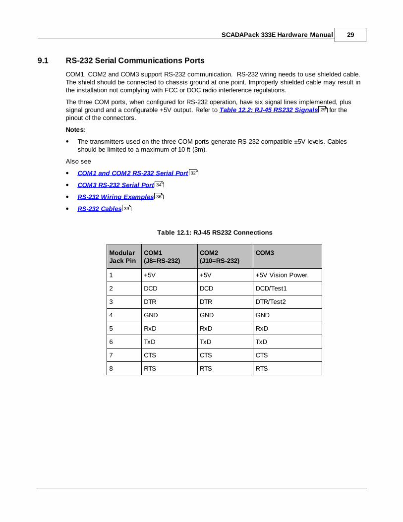
9.1 RS-232 Serial Communications Ports
COM1, COM2 and COM3 support RS-232 communication. RS-232 wiring needs to use shielded cable.The shield should be connected to chassis ground at one point. Improperly shielded cable may result inthe installation not complying with FCC or DOC radio interference regulations.
The three COM ports, when configured for RS-232 operation, have six signal lines implemented, plussignal ground and a configurable +5V output. Refer to Table 12.2: RJ-45 RS232 Signals for thepinout of the connectors.
Notes:
The transmitters used on the three COM ports generate RS-232 compatible 5V levels. Cablesshould be limited to a maximum of 10 ft (3m).
Also see
COM1 and COM2 RS-232 Serial Port
COM3 RS-232 Serial Port
RS-232 Wiring Examples
RS-232 Cables
Table 12.1: RJ-45 RS232 Connections
ModularJack Pin
COM1(J8=RS-232)
COM2(J10=RS-232)
COM3
1 +5V +5V +5V Vision Power.
2 DCD DCD DCD/Test1
3 DTR DTR DTR/Test2
4 GND GND GND
5 RxD RxD RxD
6 TxD TxD TxD
7 CTS CTS CTS
8 RTS RTS RTS
29
32
34
36
39
SCADAPack 333E Hardware Manual30
ModularJack Pin
COM1(J8=RS-232)
COM2(J10=RS-232)
COM3
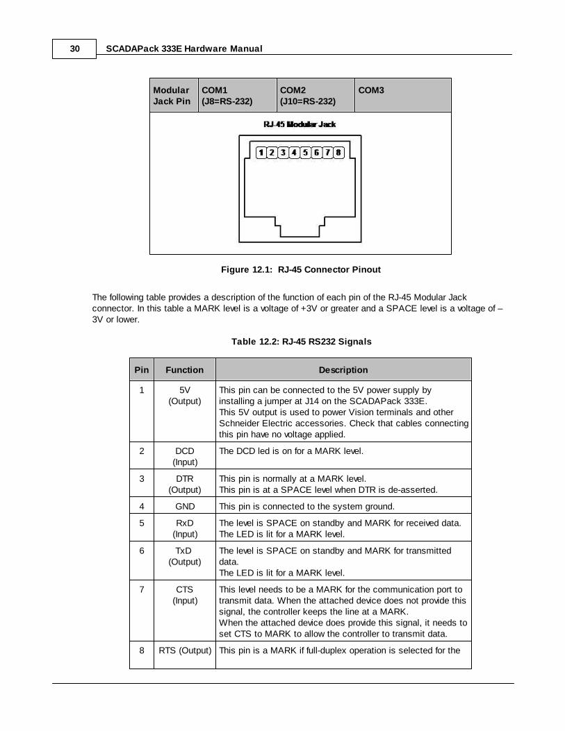
Figure 12.1: RJ-45 Connector Pinout
The following table provides a description of the function of each pin of the RJ-45 Modular Jackconnector. In this table a MARK level is a voltage of +3V or greater and a SPACE level is a voltage of –3V or lower.
Table 12.2: RJ-45 RS232 Signals
Pin Function Description
1 5V(Output)
This pin can be connected to the 5V power supply byinstalling a jumper at J14 on the SCADAPack 333E.This 5V output is used to power Vision terminals and otherSchneider Electric accessories. Check that cables connectingthis pin have no voltage applied.
2 DCD(Input)
The DCD led is on for a MARK level.
3 DTR(Output)
This pin is normally at a MARK level.This pin is at a SPACE level when DTR is de-asserted.
4 GND This pin is connected to the system ground.
5 RxD(Input)
The level is SPACE on standby and MARK for received data. The LED is lit for a MARK level.
6 TxD (Output)
The level is SPACE on standby and MARK for transmitteddata. The LED is lit for a MARK level.
7 CTS(Input)
This level needs to be a MARK for the communication port totransmit data. When the attached device does not provide thissignal, the controller keeps the line at a MARK. When the attached device does provide this signal, it needs toset CTS to MARK to allow the controller to transmit data.
8 RTS (Output) This pin is a MARK if full-duplex operation is selected for the

SCADAPack 333E Hardware Manual 31
Pin Function Description
port. This pin is set to a MARK just before and during transmissionof data if half-duplex operation is selected. This pin is set to a SPACE when no data is being transmitted.The LED is ON for a MARK level.
SCADAPack 333E Hardware Manual32
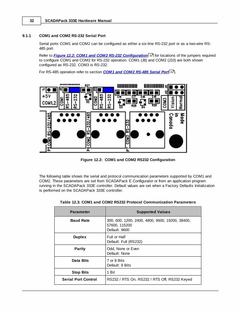
9.1.1 COM1 and COM2 RS-232 Serial Port
Serial ports COM1 and COM2 can be configured as either a six-line RS-232 port or as a two-wire RS-485 port.
Refer to Figure 12.2: COM1 and COM2 RS-232 Configuration for locations of the jumpers requiredto configure COM1 and COM2 for RS-232 operation. COM1 (J8) and COM2 (J10) are both shownconfigured as RS-232. COM3 is RS-232.
For RS-485 operation refer to section COM1 and COM2 RS-485 Serial Port .
Figure 12.2: COM1 and COM2 RS232 Configuration
The following table shows the serial and protocol communication parameters supported by COM1 andCOM2. These parameters are set from SCADAPack E Configurator or from an application programrunning in the SCADAPack 333E controller. Default values are set when a Factory Defaults Initializationis performed on the SCADAPack 333E controller.
Table 12.3: COM1 and COM2 RS232 Protocol Communication Parameters
Parameter Supported Values
Baud Rate 300, 600, 1200, 2400, 4800, 9600, 19200, 38400,57600, 115200Default: 9600
Duplex Full or HalfDefault: Full (RS232)
Parity Odd, None or EvenDefault: None
Data Bits 7 or 8 BitsDefault: 8 Bits
Stop Bits 1 Bit
Serial Port Control RS232 / RTS On, RS232 / RTS Off, RS232 Keyed
32
42

SCADAPack 333E Hardware Manual 33
Parameter Supported Values
mode, RS485 2-wire (Half Duplex)
Protocol ISaGRAF, DNP3, Command Line, PLC Device,ISaGRAF user, PPP/TCPIP, TCP service, ModbusRTU slave, DNP VT service, IEC60870-5-103 Master,IEC60870-5-101 Slave or NTP GPS receiver, None
Configuration &Diagnostics
When referenced in SCADAPack E Configuration andDiagnostic facilities, COM1 is known as PORT1 andCOM2 is known as PORT2
SCADAPack 333E Hardware Manual34
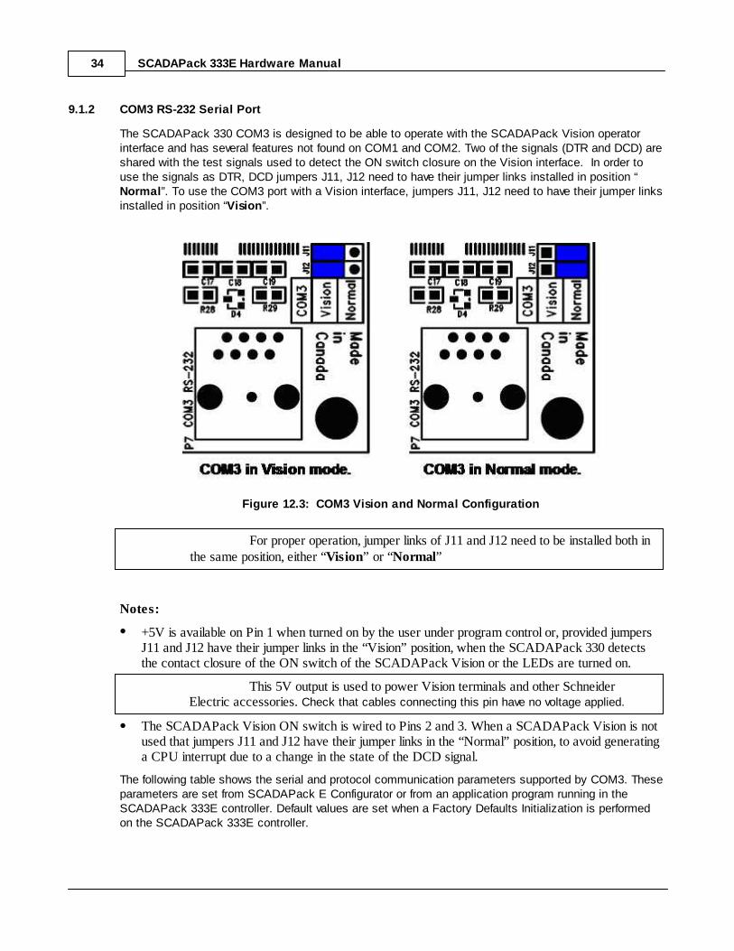
9.1.2 COM3 RS-232 Serial Port
The SCADAPack 330 COM3 is designed to be able to operate with the SCADAPack Vision operatorinterface and has several features not found on COM1 and COM2. Two of the signals (DTR and DCD) areshared with the test signals used to detect the ON switch closure on the Vision interface. In order touse the signals as DTR, DCD jumpers J11, J12 need to have their jumper links installed in position “Normal”. To use the COM3 port with a Vision interface, jumpers J11, J12 need to have their jumper linksinstalled in position “Vision”.
Figure 12.3: COM3 Vision and Normal Configuration
For proper operation, jumper links of J11 and J12 need to be installed both inthe same position, either “Vision” or “Normal”
Notes:
+5V is available on Pin 1 when turned on by the user under program control or, provided jumpersJ11 and J12 have their jumper links in the “Vision” position, when the SCADAPack 330 detectsthe contact closure of the ON switch of the SCADAPack Vision or the LEDs are turned on.
This 5V output is used to power Vision terminals and other SchneiderElectric accessories. Check that cables connecting this pin have no voltage applied.
The SCADAPack Vision ON switch is wired to Pins 2 and 3. When a SCADAPack Vision is notused that jumpers J11 and J12 have their jumper links in the “Normal” position, to avoid generatinga CPU interrupt due to a change in the state of the DCD signal.
The following table shows the serial and protocol communication parameters supported by COM3. Theseparameters are set from SCADAPack E Configurator or from an application program running in theSCADAPack 333E controller. Default values are set when a Factory Defaults Initialization is performedon the SCADAPack 333E controller.
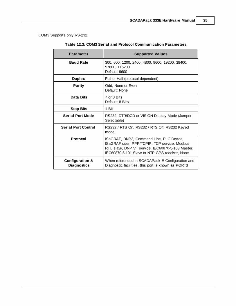
SCADAPack 333E Hardware Manual 35
COM3 Supports only RS-232.
Table 12.3: COM3 Serial and Protocol Communication Parameters
Parameter Supported Values
Baud Rate 300, 600, 1200, 2400, 4800, 9600, 19200, 38400,57600, 115200Default: 9600
Duplex Full or Half (protocol dependent)
Parity Odd, None or EvenDefault: None
Data Bits 7 or 8 BitsDefault: 8 Bits
Stop Bits 1 Bit
Serial Port Mode RS232: DTR/DCD or VISION Display Mode (JumperSelectable)
Serial Port Control RS232 / RTS On, RS232 / RTS Off, RS232 Keyedmode
Protocol ISaGRAF, DNP3, Command Line, PLC Device,ISaGRAF user, PPP/TCPIP, TCP service, ModbusRTU slave, DNP VT service, IEC60870-5-103 Master,IEC60870-5-101 Slave or NTP GPS receiver, None
Configuration &Diagnostics
When referenced in SCADAPack E Configuration andDiagnostic facilities, this port is known as PORT3
SCADAPack 333E Hardware Manual36
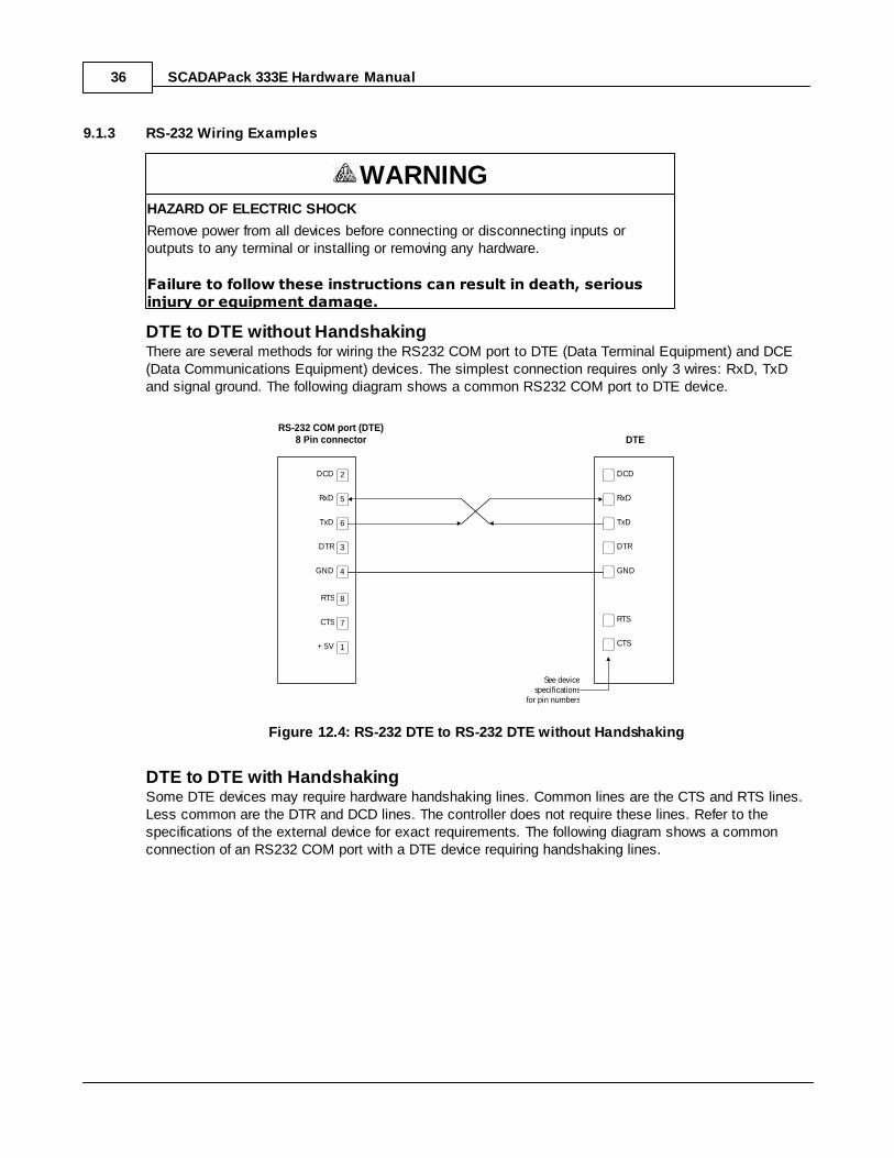
9.1.3 RS-232 Wiring Examples
WARNINGHAZARD OF ELECTRIC SHOCK
Remove power from all devices before connecting or disconnecting inputs oroutputs to any terminal or installing or removing any hardware.
Failure to follow these instructions can result in death, seriousinjury or equipment damage.
DTE to DTE without HandshakingThere are several methods for wiring the RS232 COM port to DTE (Data Terminal Equipment) and DCE(Data Communications Equipment) devices. The simplest connection requires only 3 wires: RxD, TxDand signal ground. The following diagram shows a common RS232 COM port to DTE device.
RS-232 COM port (DTE)8 Pin connector DTE
5
6
3
4
8
7
1
2DCD
RxD
TxD
DTR
GND
RTS
CTS
+ 5V
DCD
RxD
TxD
DTR
GND
RTS
CTS
See devicespecifications
for pin numbers
Figure 12.4: RS-232 DTE to RS-232 DTE without Handshaking
DTE to DTE with HandshakingSome DTE devices may require hardware handshaking lines. Common lines are the CTS and RTS lines.Less common are the DTR and DCD lines. The controller does not require these lines. Refer to thespecifications of the external device for exact requirements. The following diagram shows a commonconnection of an RS232 COM port with a DTE device requiring handshaking lines.

SCADAPack 333E Hardware Manual 37
RS-232 COM port (DTE)8 Pin connector DTE
5
6
3
4
8
7
1
2DCD
RxD
TxD
DTR
GND
RTS
CTS
+ 5V
DCD
RxD
TxD
DTR
GND
RTS
CTS
See devicespecifications
for pin numbers
Figure 12.5: RS-232 DTE to RS-232 DTE with Handshaking

SCADAPack 333E Hardware Manual38
DTE to DCE with HandshakingDCE devices require different wiring. The handshaking lines need to be connected. Many DCE devicesare half-duplex. Select half-duplex operation with these devices. The diagram below shows commonconnection of a SCADAPack 333E with a DCE device requiring handshaking lines.
RS-232 COM port (DTE)8 Pin connector DCE
5
6
3
4
8
7
1
2DCD
RxD
TxD
DTR
GND
RTS
CTS
+ 5V
DCD
RxD
TxD
DTR
GND
RTS
CTS
See devicespecifications
for pin numbers
Figure 12.6: RS-232 DTE to RS-232 DCE With Handshaking
SCADAPack 333E Hardware Manual 39
9.1.4 RS-232 Cables
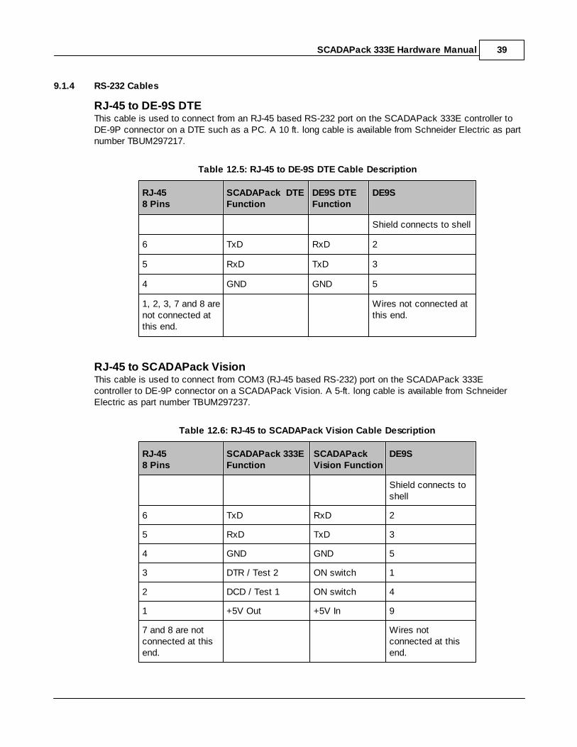
RJ-45 to DE-9S DTEThis cable is used to connect from an RJ-45 based RS-232 port on the SCADAPack 333E controller toDE-9P connector on a DTE such as a PC. A 10 ft. long cable is available from Schneider Electric as partnumber TBUM297217.
Table 12.5: RJ-45 to DE-9S DTE Cable Description
RJ-45 8 Pins
SCADAPack DTEFunction
DE9S DTEFunction
DE9S
Shield connects to shell
6 TxD RxD 2
5 RxD TxD 3
4 GND GND 5
1, 2, 3, 7 and 8 arenot connected atthis end.
Wires not connected atthis end.
RJ-45 to SCADAPack VisionThis cable is used to connect from COM3 (RJ-45 based RS-232) port on the SCADAPack 333Econtroller to DE-9P connector on a SCADAPack Vision. A 5-ft. long cable is available from SchneiderElectric as part number TBUM297237.
Table 12.6: RJ-45 to SCADAPack Vision Cable Description
RJ-45 8 Pins
SCADAPack 333EFunction
SCADAPackVision Function
DE9S
Shield connects toshell
6 TxD RxD 2
5 RxD TxD 3
4 GND GND 5
3 DTR / Test 2 ON switch 1
2 DCD / Test 1 ON switch 4
1 +5V Out +5V In 9
7 and 8 are notconnected at thisend.
Wires notconnected at thisend.
SCADAPack 333E Hardware Manual40
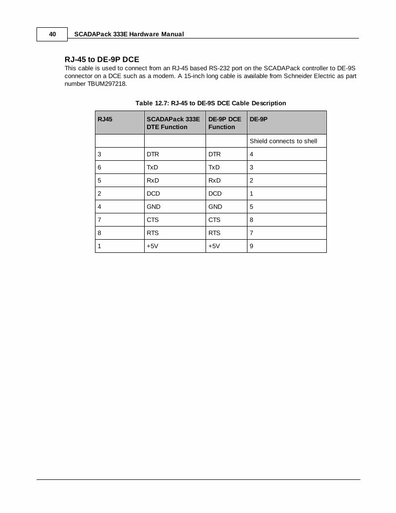
RJ-45 to DE-9P DCEThis cable is used to connect from an RJ-45 based RS-232 port on the SCADAPack controller to DE-9Sconnector on a DCE such as a modem. A 15-inch long cable is available from Schneider Electric as partnumber TBUM297218.
Table 12.7: RJ-45 to DE-9S DCE Cable Description
RJ45 SCADAPack 333EDTE Function
DE-9P DCEFunction
DE-9P
Shield connects to shell
3 DTR DTR 4
6 TxD TxD 3
5 RxD RxD 2
2 DCD DCD 1
4 GND GND 5
7 CTS CTS 8
8 RTS RTS 7
1 +5V +5V 9

SCADAPack 333E Hardware Manual 41
9.2 RS-485 Serial Communication Ports
COM1 and COM2 RS-485 Serial Port
RS-485 Bias & Termination Resistors
RS-485 Wiring Examples
42
45
47

SCADAPack 333E Hardware Manual42
9.2.1 COM1 and COM2 RS-485 Serial Port
COM1 and COM2 support RS-485 communications. RS-485 wiring needs to use shielded cable. Theshield should be connected to chassis ground at one point. Improperly shielded cable may result in the
installation not complying with FCC or DOC radio interference regulations.
Serial port COM1 and COM2 can be configured as either a six-line RS-232 port or as a two-wire RS-485port. This section covers RS-485 operation. For RS-232 operation refer to Section COM2 RS-232 SerialPort .
Refer to Figure 12.7: COM1 and COM2 RS-485 Configuration for the locations of the jumpers J8and J10 required to configure COM1 and COM2. COM1 and COM2 are both shown configured toRS-485. COM3 is RS-232.
Figure 12.7: COM1 and COM2 RS-485
Table 12.8: RS-485 Connections
ModularJack Pin
COM1(J8=RS-232)
COM2(J10=RS-232)
1 +5V when J7 installed +5V when J7 installed
2 No Connection No Connection
3 No Connection No Connection
4 GND GND
5
6
7 No Connection No Connection
8 No Connection No Connection
32

SCADAPack 333E Hardware Manual 43
ModularJack Pin
COM1(J8=RS-232)
COM2(J10=RS-232)
COM1 and COM2 transmits and receives differential voltages to other RS-485 devices on a network. TheRS-485 specification allows a maximum of 32 devices connected on a single RS-485 network. Thespecification for RS-485 recommends that the cable length should not exceed a maximum of 4000 feetor 1200 meters.
The signal grounds of the RS-485 devices in the network are not connected together but instead arereferenced to their respective incoming electrical grounds. The grounds of the RS-485 devices on thenetwork need to be within several volts of each other. Controller ground is connected to the chassis.
The following table provides a description of the function of each pin of the RJ-45 connector.
Table 12.10: RJ-45 Connector Pin Description
Pin Function Description
1 5V(Output)
This pin can be connected to the 5V power supply byinstalling a jumper at J14 on the SCADAPack 333E.
2 NC Not used in RS-485 mode. Should be left open.
3 NC Not used in RS-485 mode. Should be left open.
4 GND This pin is connected to the system ground.
5
(Input/Output)
For RS-485 operation J13 needs to have the jumper link inposition “RS-485”
This pin is the B signal of the RS-485 bus.
6
(Input/Output)
For RS-485 operation J13 needs to have the jumper link inposition “RS-485”
his pin is the A signal of the RS-485 bus.
7 NC Not used in RS-485 mode. Should be left open.
8 NC Not used in RS-485 mode. Should be left open.

SCADAPack 333E Hardware Manual44
Connections to COM2 are made through a RJ-45 modular connector. COM2 supports two signals plusGround and 5V power. The following diagram shows the pin connections for the RS-485 (RJ-45) portconnector for COM2 operating in RS-485 mode.

SCADAPack 333E Hardware Manual 45
The following table shows the serial and protocol communication parameters supported by COM1 andCOM2. These parameters are set from SCADAPack E Configurator or from an application programrunning in the RTU.
Default values are set when a Factory Defaults Initialization (Cold Boot) is performed on the SCADAPack333E controller.
Table 12.9: COM1 and COM2 RS485 Communication Parameters
Parameter Supported Values
Baud Rate 300, 600, 1200, 2400, 4800, 9600, 19200, 38400,57600, 115200Default: 9600
Duplex HalfDefault: Half
Parity Odd, None or EvenDefault: None
Data Bits 7 or 8 BitsDefault: 8 Bits
Stop Bits 1 BitDefault: 1 Bit
Receive Flow Control None
Transmit Flow Control None
Protocol ISaGRAF, DNP3, Command Line, PLC Device,ISaGRAF user, PPP/TCPIP, TCP service, Modbusslave, DNP VT service, IEC 60870-5-103 Master, IEC60870-5-101 Slave or NTP GPS Receiver
Default: DNP3
Configuration &Diagnostics
When referenced in SCADAPack E Configuration andDiagnostic facilities, this port is known as PORT2
9.2.2 RS-485 Bias & Termination Resistors
RS-485 Bias ResistorsThe RS-485 receiver inputs on the controller are biased so that that received data is driven to a validstate (space) when there are no active drivers on the network. The value of these bias resistors is 5100ohms from Ground to the B inputs and 5100 ohms from +5V to the A inputs.
RS-485 Termination ResistorsTermination resistors are required in long networks operating at the highest baud rates. Networks aslong 4000 ft. operating at 9600 baud will function without termination resistors. Terminations should onlybe considered if the baud rate is higher.

SCADAPack 333E Hardware Manual46
When termination resistors are required, they are installed on the first and last station on the RS-485wire pair. Other stations should not have termination resistors.
If required, RS-485 networks are terminated with 120-ohm resistors on each end. The required 120-ohmresistor needs to be supplied and installed by the user. When using termination resistors it may benecessary to increase the line biasing by adding lower value bias resistors in order to generate at least0.2V across RS-485 line. The suggested value of the bias resistors is 470 ohms. One bias resistor isinstalled from the B signal to COM. The second bias resistor is installed from the A signal to +5V. +5Vis available on P8 pin 1 when J7 is installed.
SCADAPack 333E Hardware Manual 47
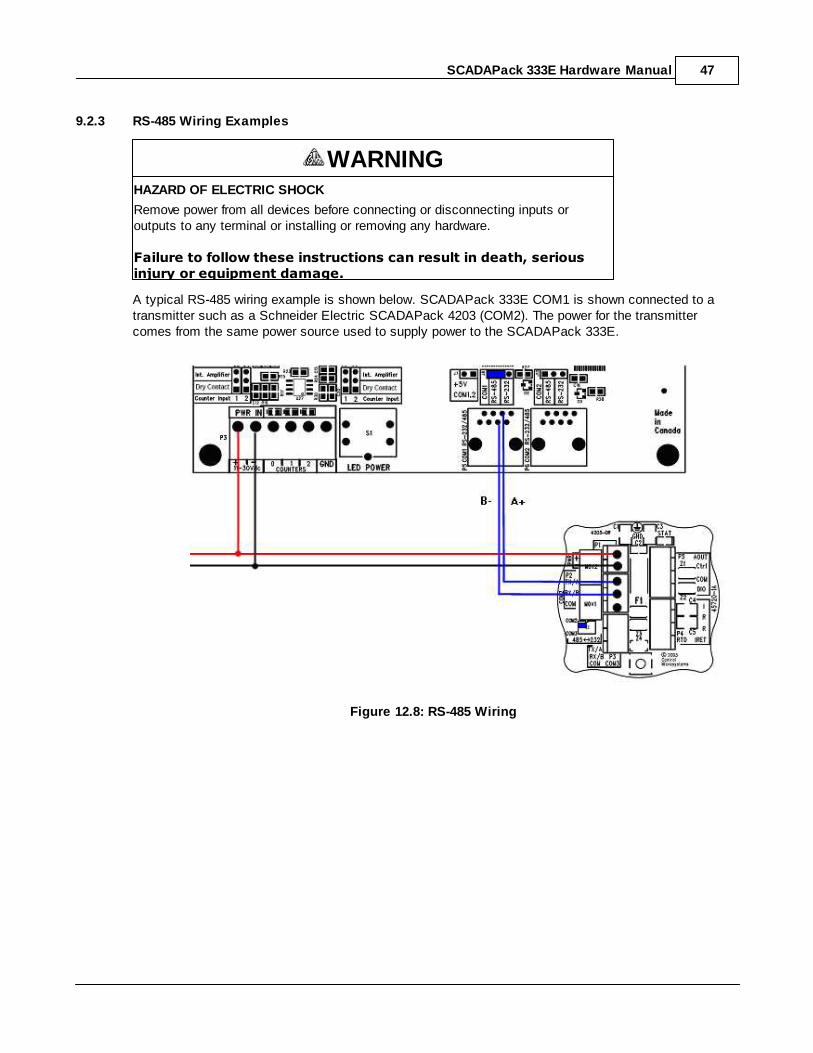
9.2.3 RS-485 Wiring Examples
WARNINGHAZARD OF ELECTRIC SHOCK
Remove power from all devices before connecting or disconnecting inputs oroutputs to any terminal or installing or removing any hardware.
Failure to follow these instructions can result in death, seriousinjury or equipment damage.
A typical RS-485 wiring example is shown below. SCADAPack 333E COM1 is shown connected to atransmitter such as a Schneider Electric SCADAPack 4203 (COM2). The power for the transmittercomes from the same power source used to supply power to the SCADAPack 333E.
Figure 12.8: RS-485 Wiring

SCADAPack 333E Hardware Manual48
10 Ethernet Communication
The SCADAPack 333E controller has one 10/100Base-T Ethernet port. This is a single communicationschannel running at 10/100 Mb/s over unshielded, twisted - pair cabling, using differential signaling. Itsupports both half-duplex and full-duplex operation. The interface supports auto-negotiation for both thespeed and half/ full-duplex mode selection.
LAN Port Settings
RJ-45 Modular Connector for Ethernet
49
54

SCADAPack 333E Hardware Manual 49
10.1 LAN Port Settings
Connections to the LAN port are made through a RJ-45 modular connector. The wiring and pinconnections for this connector are described in Section RJ-45 Modular Connector for Ethernet .
Refer to Section Field Wiring for the location of the LAN port on the SCADAPack controller board.
When referred to in SCADAPack E configuration and diagnostic facilities, the LAN port is referred to as
communications channel number 10.
TCP/IP Settings
Modbus/TCP Settings
54
11
50
51

SCADAPack 333E Hardware Manual50
10.1.1 TCP/IP Settings
The following table shows the TCP/IP parameters supported by the LAN port. These parameters are setfrom SCADAPack E Configurator.
Default values are set when a Factory Default Initializations (Cold Boot) is performed on the controller.
Table 13.1: TCP/IP Parameters
Parameter Supported Values
IP Address In the format 255.255.255.255
Default: 0.0.0.0
Subnet Mask In the format 255.255.255.255
Default: 0.0.0.0
Gateway To enter a Default Gateway address, enter an IP RouteTable entry as described below.
The IP Address is the address of the controller. The IP address is statically assigned. Contact yournetwork administrator to obtain an IP address for the controller.
The Subnet Mask is determines the subnet on which the controller is located. The subnet mask isstatically assigned. Contact your network administrator to obtain the subnet mask for the controller.
The Gateway determines how your controller communicates with devices outside its subnet.
Enter the IP address of a default gateway node in the IP Route Table on the Advanced TCP/IP settingsin the format:
Dest. IP Addr. Subnet Mask Dest. Port Gateway IP Metric
Port Number ofinterface
Gateway IPAddress
0
The gateway is statically assigned. Contact your network administrator to obtain the gateway IPaddress. The default gateway address needs to be a node on the subnet associated with the Dest. Port- i.e. it needs to be part of the subnet defined for the interface. In many cases this will be the Ethernetinterface, and so the gateway IP address needs to be part of the Ethernet subnet.
For more information see the SCADAPack E TCP/IP Technical Reference manual.

SCADAPack 333E Hardware Manual 51
10.1.2 Modbus/TCP Settings
Modbus/TCP Client (Master)
Modbus/TCP Client configurations are set by ISaGRAF I/O mtcpXXX i/o boards.
By default, the TCP/IP Service for the Modbus/TCP Client is DISABLED. To Enable it, use SCADAPackE Configurator TCP/IP page and check the Modbus/IP (Client) check box to enable the service.
For more information see SCADAPack E Modbus Communication Interfaces manual.
Modbus/TCP Server (Slave)
The following table shows the Modbus/TCP Server (slave) parameters supported by the SCADAPack ETCP/IP interfaces. These parameters are set from the ISaGRAF Workbench or from an applicationprogram running in the controller.
Default values are set when a Factory Defaults Initialization (Cold Boot) is performed on the RTU.
Table 13.2: Modbus/TCP Server Parameters
Parameter Supported Values
TCP/IP Services
Modbus/TCP (Server)
Enabled or Disabled
Default: Disabled
Maximum ServerConnections
Fixed: 20
TCP Port Fixed: 502
Modbus Addressing Type Fixed: Standard - Unit Identifier
Modbus/TCP Server UnitIdentifer
Valid values are 1 to 247.
Default: 1
Store and ForwardMessaging
Not Supported
By default, the TCP/IP Service for the Modbus/TCP Server is DISABLED. To Enable it, use SCADAPackE Configurator Slave / Modbus page and check the Modbus/TCP (Server) tick-box.
The Maximum Server Connections parameter limits the number of incoming (server) connections thatthe controller will allow. Incoming (server) connections are used when a remote device creates aconnection to this controller.
The TCP Port parameter is fixed by the Modbus/TCP protocol. This is the well-known port number forModbus/TCP. Modbus/TCP devices use 502 by default, and on many devices the value cannot bechanged.
The Addressing parameter is fixed to Standard addressing allowing choice of one of 247 stationaddresses for this RTU's Modbus/TCP server. The addressing is compatible with standard Modbusdevices.

SCADAPack 333E Hardware Manual52
The Modbus/TCP Server Unit Identifier parameter sets the station number of the controller. The validrange is 1 to 247.
Store and Forward Messaging is not supported for Modbus/TCP communications on SCADAPack ERTUs.
For a complete description of Modbus/TCP Server operation, see the SCADAPack E ModbusCommunication Interfaces manual.

SCADAPack 333E Hardware Manual 53
10.1.3 Modbus RTU in TCP Settings
Modbus RTU in TCP Client (Master)
Modbus RTU in TCP Client configurations are set by ISaGRAF I/O mrtpXXX I/O boards.
By default, the TCP/IP Service for the Modbus/IP (Client) is DISABLED. To Enable it, use SCADAPackE Configurator TCP/IP page and check the Modbus/IP (Client) tick-box.
For more information see SCADAPack E Modbus Communication Interfaces manual.
For a complete description of Modbus RTU in TCP Client operation, see the SCADAPack E ModbusCommunication Interfaces manual.

SCADAPack 333E Hardware Manual54
10.2 RJ-45 Modular Connector for Ethernet
The SCADAPack 333E can be connected directly to a wall jack or hub using standard RJ-45 Category 5patch cables. The following diagram shows the pin connections for the RJ-45 modular connector.
RJ-45 Modular JackGrey
1. + Tx2. –Tx3. + Rx4. 5. 6. –Rx7. 8.
21 876543
Figure 13.1: RJ-45 Connector for Ethernet
10/100Base-T has a maximum run of 100m or 350 feet, but the actual limit is based on signal loss andthe noise in the environment. This may limit the practical distance to less than 100m or 350 feet. TheEthernet cables should not be run in parallel with power or any cables that generate noise.

SCADAPack 333E Hardware Manual 55
11 USB Ports & Connections
USB PortsThe SCADAPack 333E controller has two USB 2.0 compliant ports, supporting both low-speed (1.5Mb/s) and full-speed (12Mb/s). One of the ports allows the controller to act as a host (Host Port), while thesecond port allows connection to a USB host (Peripheral Port), such as a notebook computer. The twoUSB ports can be used simultaneously.
USB Peripheral Port - provides DNP3 communications for local connection to SCADAPack EConfigurator.
USB Host Port - Not currently supported by SCADAPack E operating system.
WARNING
USB ports may be permanently used in non-hazardous applications.
USB ports may be used for corrective maintenance in locations classified ashazardous but are known to be in a non-hazardous state.
USB ConnectionsThe connectors used for the USB ports are compliant with the USB specification.

SCADAPack 333E Hardware Manual56
11.1 Peripheral & Host Port
Peripheral PortThe peripheral port uses a USB series “B” receptacle.
The peripheral port is used for local connection of SCADAPack E Configurator using DNP3 protocol.
This ports correspond to PORT0 when using SCADAPack E Configurator and in SCADAPack Ediagnostics.
A SCADAPack 333E will not draw any significant power from the host over the USB peripheral port. Thefollowing diagram shows the connections of the peripheral USB port.
Table 14.1: USB Peripheral Port Communication Parameters
Parameter Supported Values
USB USB 2.0 compliant, Peripheral port
Data Rate Auto detect.
Low-speed (1.5Mb/s) and Full-speed (12Mb/s)
Protocol DNP3
Configuration &Diagnostics
When referenced in SCADAPack E Configuration andDiagnostic facilities, this port is known as PORT0
Figure 14.2: Peripheral USB Port Connections
Host PortThe host port features a USB series “A” receptacle. For bus-powered USB devices, the host port canprovide up to 100mA at 5V. The following diagram shows the connections for the host USB port.

SCADAPack 333E Hardware Manual 57
USB series “A”receptacle
1. VBUS2. D-3. D+4. GND
3
4
1
2
Figure 14.1: Host USB Port Connections
This port is not currently supported by the SCADAPack E operating system.
SCADAPack 333E Hardware Manual58
12 Operation
Operating Modes
LED Indicators
LED Power Control
Jumpers
Status LED
59
66
67
67
68

SCADAPack 333E Hardware Manual 59
12.1 Operating Modes
WARNINGUNEXPECTED EQUIPMENT OPERATION
Evaluate the operational state of the equipment monitored and controlled by theSCADAPack E RTU prior to initializing the SCADAPack E RTU.
Failure to follow these instructions can result in death, seriousinjury or equipment damage.
A SCADAPack 300E may start up in RUN, SERVICE, COLD BOOT or FACTORY BOOT modes.
Start up in the RUN mode automatically loads the RTU database, executes ISaGRAF programs inthe controller memory, and communicates on its interfaces, as per its configuration.
Start up in the SERVICE mode stops the ISaGRAF user applications and overrides RTU ports withDNP3 communications at node address “0” to allow controller reprogramming and initialization.
Start up in the COLD BOOT mode initializes the controller and erases user application programs.
Start up in FACTORY BOOT reformats the Flash file system, initializes the controller and erasesuser application programs.
Each boot mode is determined by the amount of time that the LED power switch is depressed whenpower is applied or a board reset occurs.
The boot mode is not performed until the LED power switch is released. As such power can be removedprior to releasing the LED power switch without performing the selected boot mode.
The following sections describe in detail the selection of each operating mode.
Run Mode
Service Mode
Cold Boot Mode
Factory Boot Mode
Boot Mode Effects
60
61
62
64
65

SCADAPack 333E Hardware Manual60
12.1.1 Run Mode
The RUN mode is the normal operating mode of the controller. No action is required to select RUNmode.
When the controller starts:
The RTU loads the defined serial and Ethernet communication parameters, for every COM port.
RTU database configuration and point attributes are loaded
ISaGRAF application programs are loaded and executed
If there is no ISaGRAF application program in RAM and there is an application program in flashROM then the flash ROM program will be loaded in RAM and executed.
SCADAPack 333E Hardware Manual 61
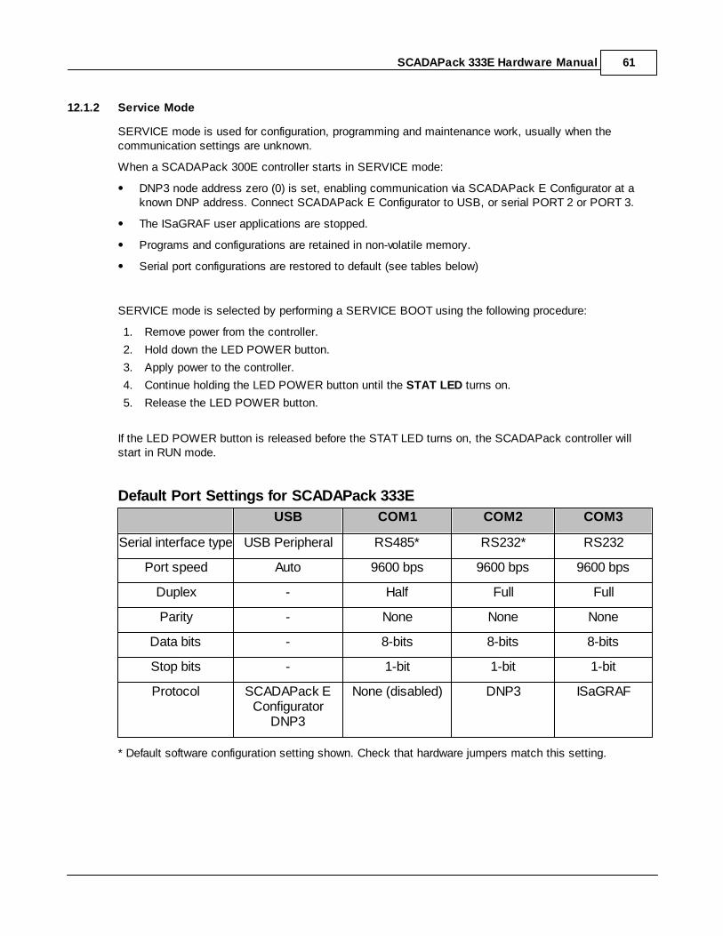
12.1.2 Service Mode
SERVICE mode is used for configuration, programming and maintenance work, usually when thecommunication settings are unknown.
When a SCADAPack 300E controller starts in SERVICE mode:
DNP3 node address zero (0) is set, enabling communication via SCADAPack E Configurator at aknown DNP address. Connect SCADAPack E Configurator to USB, or serial PORT 2 or PORT 3.
The ISaGRAF user applications are stopped.
Programs and configurations are retained in non-volatile memory.
Serial port configurations are restored to default (see tables below)
SERVICE mode is selected by performing a SERVICE BOOT using the following procedure:
1. Remove power from the controller.
2. Hold down the LED POWER button.
3. Apply power to the controller.
4. Continue holding the LED POWER button until the STAT LED turns on.
5. Release the LED POWER button.
If the LED POWER button is released before the STAT LED turns on, the SCADAPack controller willstart in RUN mode.
Default Port Settings for SCADAPack 333E
USB COM1 COM2 COM3
Serial interface type USB Peripheral RS485* RS232* RS232
Port speed Auto 9600 bps 9600 bps 9600 bps
Duplex - Half Full Full
Parity - None None None
Data bits - 8-bits 8-bits 8-bits
Stop bits - 1-bit 1-bit 1-bit
Protocol SCADAPack EConfigurator
DNP3
None (disabled) DNP3 ISaGRAF
* Default software configuration setting shown. Check that hardware jumpers match this setting.
SCADAPack 333E Hardware Manual62
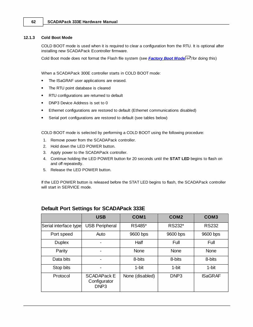
12.1.3 Cold Boot Mode
COLD BOOT mode is used when it is required to clear a configuration from the RTU. It is optional afterinstalling new SCADAPack Econtroller firmware.
Cold Boot mode does not format the Flash file system (see Factory Boot Mode for doing this)
When a SCADAPack 300E controller starts in COLD BOOT mode:
The ISaGRAF user applications are erased.
The RTU point database is cleared
RTU configurations are returned to default
DNP3 Device Address is set to 0
Ethernet configurations are restored to default (Ethernet communications disabled)
Serial port configurations are restored to default (see tables below)
COLD BOOT mode is selected by performing a COLD BOOT using the following procedure:
1. Remove power from the SCADAPack controller.
2. Hold down the LED POWER button.
3. Apply power to the SCADAPack controller.
4. Continue holding the LED POWER button for 20 seconds until the STAT LED begins to flash onand off repeatedly.
5. Release the LED POWER button.
If the LED POWER button is released before the STAT LED begins to flash, the SCADAPack controllerwill start in SERVICE mode.
Default Port Settings for SCADAPack 333E
USB COM1 COM2 COM3
Serial interface type USB Peripheral RS485* RS232* RS232
Port speed Auto 9600 bps 9600 bps 9600 bps
Duplex - Half Full Full
Parity - None None None
Data bits - 8-bits 8-bits 8-bits
Stop bits - 1-bit 1-bit 1-bit
Protocol SCADAPack EConfigurator
DNP3
None (disabled) DNP3 ISaGRAF
64

SCADAPack 333E Hardware Manual 63
* Default software configuration setting shown. Check that hardware jumpers match this setting.

SCADAPack 333E Hardware Manual64
12.1.4 Factory Boot Mode
FACTORY BOOT mode is used to reformat the Flash File system and initialize the SCADAPack 300Econtroller to factory default settings.
When the controller starts in FACTORY BOOT mode:
The ISaGRAF user applications are erased.
The RTU point database is cleared
RTU configurations are returned to default
Flash File system is reformatted
Ethernet configurations are restored to default (Ethernet communications disabled)
Serial port configurations are restored to default (see tables in Cold Boot Mode )
FACTORY BOOT mode is selected by performing the following procedure:
1. Remove power from the SCADAPack controller.
2. Hold down the LED POWER button.
3. Apply power to the SCADAPack controller.
4. Continue holding the LED POWER button for longer than 30 seconds until the STAT LED turnssolid.
5. Release the LED POWER button.
The FACTORY boot will take approximately 60 seconds to complete. During this time the controllermay appear unresponsive while the file system is being formatted to fix any corruption. The STAT LEDwill remain on until the FACTORY boot has completed and the controller restarts.
62

SCADAPack 333E Hardware Manual 65
12.1.5 Boot Mode Effects
The table below summarizes the effects of the various boot modes.
Table 15.1: Effects of Various Boot Modes
RunMode
ServiceMode
ColdBoot
FactoryBoot
Action
X X X DNP node address set tozero (0)
X serial ports protocol set toDNP3
X X serial settings set todefault
X X LED power set to default
X X Database initialized
X X ISaGRAF applicationserased
X Files are erased
X Flash File Systemreformatted
X ISaGRAF applicationsstarted
X Settings retained in non-volatile memory
X X ISaGRAF applications inflash erased
X X Protocols are set todefaults

SCADAPack 333E Hardware Manual66
12.2 LED Indicators
The table below describes the LEDs on the SCADAPack 333E. LEDs can be disabled to conservepower.
Table 15.3: SCADAPack 333E LED Descriptions
LED Function
PowerMode
On when operating and the LEDs are enabled.
Off when the LEDs are disabled
Off when powered off
RUN Blinking every 1.5 secs when the RTU is operating normally
For detailed information about indication of RTU startup phases see the SCADAPack E Operational Reference manual.
STAT Blinking when there is a status code requiring attention. The status codeand description can be viewed from SCADAPack E Configurator's General| Controller Status page. The status code is also available in SCADAPackE Analog System Point 50020
FORCE On when I/O points are forced (LOCKED by ISaGRAF)
USB STAT This is under control of SCADAPack E Binary System Point 50611.It may be controlled by an ISaGRAF application or from protocol controlcommands.
LINK On when the LAN port has established a link
ACT. On to signal activity on the LAN port
RX On when receiving data on the corresponding serial port
TX On when transmitting data on the corresponding serial port
CTS On when the CTS input is asserted COM2
DCD On when the DCD input is asserted COM2
Counter 0 On when the counter input is present and low
Counters1,2
When the input is configured to use an external amplifier, the LED is onwhen the counter input is present and low.
When the input is configured to use the internal amplifier, the LED is onwhen input pulses are present

SCADAPack 333E Hardware Manual 67
12.3 LED Power Control
The SCADAPack 333E controller board can disable the LEDs on the controller board and the 5000Series I/O modules to conserve power. This is particularly useful in solar powered or unattendedinstallations.
The Power Mode LED on the controller board indicates the LED power state. It is on when the controllerboard enables LED power.
The LED POWER push-button toggles the LED power signal. Press the LED POWER push-button totoggle LED power from off to on, or from on to off.
The SCADAPack E Configurator enables the LED power mode.
If the LED Power always On control in the General / Controller Modes page is active, the LED POWERbutton has no effect and the SCADAPack 333E LEDs and 5000 Series I/O LEDs are on.
If the LED Power always On control SCADAPack E Configurator is inactive, the state of LEDs at RTUstartup is Enabled. 60 seconds after the controller has started the LEDs will be Disabled. While thecontroller is running, when the LED POWER button is pushed the LED displays are Enabled for a periodof 60 seconds. After this time the LED displays are again disabled.
The LED state is independent of the Vision display controls on the SCADAPack 300E RTU. The usermay programmatically relate these items together through ISaGRAF logic if required (e,g. activate theDC/DC converter and Vision display when the LEDs are activated).
12.4 Jumpers
Headers on the SCADAPack 333E are user configurable and are described in the appropriate sections ofthis manual. Some headers and jumpers on the controller are reserved for manufacturing and testfunctions. Refer to Figure 5.1: SCADAPack 333E Board Layout for the location of jumpers.
The following table lists the jumpers and the relevant section of this manual.
Table 15.4: SCADAPack 333E Jumpers
Jumper Function
J3, J5 Counter Input 1 Type See Figure 11.1: Counter Input Wiring
J4, J6 Counter Input 2 Type See Figure 11.1: Counter Input Wiring
J7 +5V Power to COM1 and COM2 See COM2 RS-232 Serial Port
J8 COM1 RS-232 / RS-485 mode selection See COM1 and COM 2 RS-232 Serial Port
J9 Reset Jumper (Performs a controller board reset similar to power cycle)
J10 COM2 RS-232 / RS-485 mode selection See COM1 and COM 2 RS-232 Serial Port
J11, J12 COM3 Vision / Normal mode select COM3 RS-232 Serial Port
These jumpers need to be both in the same position, either Vision or Normal.
12 12
22
22
32
34
34
34

SCADAPack 333E Hardware Manual68
12.5 Status LED
The STAT LED indicates the current RTU status condition.
The STAT LED blinks when a status code requiring attention is present
The STAT LED turns off when the status code is returned to 0.
The RTU status condition causing the STAT LED can be determined from the RTU's system point 50020or by viewing SCADAPack E Configurator General / Controller Status page - System Error Code field.
To clear the status code and the STAT LED indicator, press the Clear Errors button on SCADAPack EConfigurator General / Controller Status page.
13 Maintenance
The SCADAPack 333E, as with other SCADAPack controllers, requires little maintenance. The PowerMode LED indicates the status of the 5V supply. If the LED is off, the on board fuse F1 may requirereplacing. If the program is lost during power outages, the lithium battery may require replacement.
The analog input and output circuitry is calibrated at the factory and does not require periodic calibration.Calibration may be necessary if the module has been repaired as a result of damage.
If the controller is not functioning correctly, contact Schneider Electric Technical Support for informationregarding returning the SCADAPack E Smart RTU for repair.
WARNINGHAZARD OF ELECTRIC SHOCK
Remove power from all devices before connecting or disconnecting inputs oroutputs to any terminal or installing or removing any hardware.
Failure to follow these instructions can result in death, seriousinjury or equipment damage.
Fuses
Lithium Battery
69
70
SCADAPack 333E Hardware Manual 69
13.1 Fuses
A single 1.5 Amp fast-blow fuse provides protection for the power supply. The fuse is mounted under thecover. Refer to Figure 5.1: SCADAPack 333E Board Layout for the location.
WARNINGRISK OF EXPLOSION
Before replacing the fuse verify that the area is non-hazardous and disconnectpower.
Failure to follow these instructions can result in death, seriousinjury or equipment damage.
Before replacing the fuse assess the impact that disconnecting power may have on other devices.
WARNINGUNEXPECTED EQUIPMENT OPERATION
Evaluate the operational state of the equipment monitored and controlled by theSCADAPack E RTU.
Failure to follow these instructions can result in death, seriousinjury or equipment damage.
Replace a blown fuse with a fuse of the same rating. Under no circumstances should a fuse bebypassed or replaced with a fuse of a higher rating.
WARNINGUNEXPECTED EQUIPMENT OPERATION
Replace the fuse with a fuse of the same rating.
Failure to follow these instructions can result in death, seriousinjury or equipment damage.
The fuse is a Littelfuse Nano-SMF, part number 045301.5 or R45101.5. This fuse is available in apackage of 10 from Schneider Electric as part number TBUM297327.
In every case investigate and correct the cause of the blown fuse before replacement. Common causesof a blown fuse are short circuits and excessive input voltages.
12

SCADAPack 333E Hardware Manual70
13.2 Lithium Battery
A small lithium battery powers the CMOS memory and real-time clock when input power is removed.The voltage of a functioning battery should be greater than 3.0V (typically 3.5 ~ 3.7V). The SCADAPack300E RTUs monitor the lithium battery and provide a status indication if the battery voltage is less than3.0V (RAM Battery Low - Binary System Point 50207). See Internal Binary Points .
The battery should not require regular replacement under normal conditions. The shelf life of the batteryis 10 years. The battery is rated to maintain the real-time clock and RAM data for two years with thepower off. Accidental shorting or extreme temperatures may damage the battery.
Battery Replacement ProcedureThe battery is plugged into the circuit board and held in place with a tie-wrap. If necessary it can bereplaced with an identical battery available from Schneider Electric.
1. Save the existing configuration and ISaGRAF user applications running in the RTU, if applicable.
2. Remove power from the RTU.
3. Remove the RTU top cover and locate the battery. It is found at the far right side of the circuitboard.
4. The battery is wrapped in place at the factory. This is to keep the battery from becomingdisconnected during shipment. Remove the tie wrap using wire cutters.
5. Remove the battery by gently lifting it straight up from the circuit board. The battery has two pinsthat mate with two sockets on the circuit board.
6. Replace the battery. A replacement tie wrap is not necessary.
7. Cold boot the controller. (Refer to Section Cold Boot Mode in of this manual for the Cold Bootprocedure.)
If a cold boot is not done, the behaviour of the controller is unpredictable.
8. The controller's configuration and applications may now be loaded.
20
62

SCADAPack 333E Hardware Manual 71
14 Troubleshooting
Counter Inputs
Condition Action
Input LED does not come onwhen input signal is applied.
Check the input signal at the termination block. Itshould be at least 50% of the counter input range.
Check the LEDs are turned on.

SCADAPack 333E Hardware Manual72
15 Specifications
Disclaimer: Control Microsystems Inc. reserves the right to change product specifications withoutnotice. For more information visit http://www.schneider-electric.com.
General & Controller
Data Capaciity
Serial Ports
Ethernet Port & USB Ports
Visual Indicators
Power Supply & I/O Expansion
Counter Inputs
73
74
75
77
78
79
81

SCADAPack 333E Hardware Manual 73
15.1 General & Controller
General
I/O Terminations 8 pole, removable terminal block
12 to 22 AWG
15A contacts
Screw termination - 6 lb.-in. (0.68 Nm) torque
Dimensions 5.65 inch (144mm) wide
5.00 inch (127 mm) high
1.80 inch (45mm) deep
Packaging Corrosion resistant zinc plated steel with black enamel paint
Environment 5% RH to 95% RH, non-condensing
–25ºC to 70oC (–13ºF to 158ºF) operation
–40ºC to 85ºC (–40ºF to 185ºF) storage
Controller
Processors 32-bit ARM7-TDMI microcontroller, 32 MHz clock
integrated watchdog timer
Microcontroller I/O co-processors, 20 MHz clock
Memory 16MBytes FLASH ROM
4MBytes CMOS RAM
4kBytes EEPROM
Non-volatileRAM
CMOS RAM with lithium battery retains contents for 2 yearswith no power
Clock calendar 1 minute/month at 25°C
+1/–3 minutes/month 0 to 50°C
Internaltemperature
Measurement range -40°C to 75°C. Accuracy 5°C.
Measurement range -40°F to 167°F. Accuracy 9°F.
Lithium BatteryMonitor
Accuracy 0.2V (status indicated by Internal Binary Point )
Power InputVoltage Monitor
Accuracy 0.4V.
20

SCADAPack 333E Hardware Manual74
15.2 Data Capaciity
MaximumDatabase Points
Approx. 1,000
Maximum DNP3Events
20,000
Maximum DataConcentratorpoints
500
Maximum DataConcentratorDevices
10
File SystemTypical Storage
5 MB
Trend samplefiles
80 (when no user programming used)
Integers 20,000
Floats 10,000
Trendaggregation
up to 5 MB (with ISaGRAF Restart History programming. SeeSCADAPack E Trend Sampler Technical manual)
Integers 1,200,000
Floats 600,000
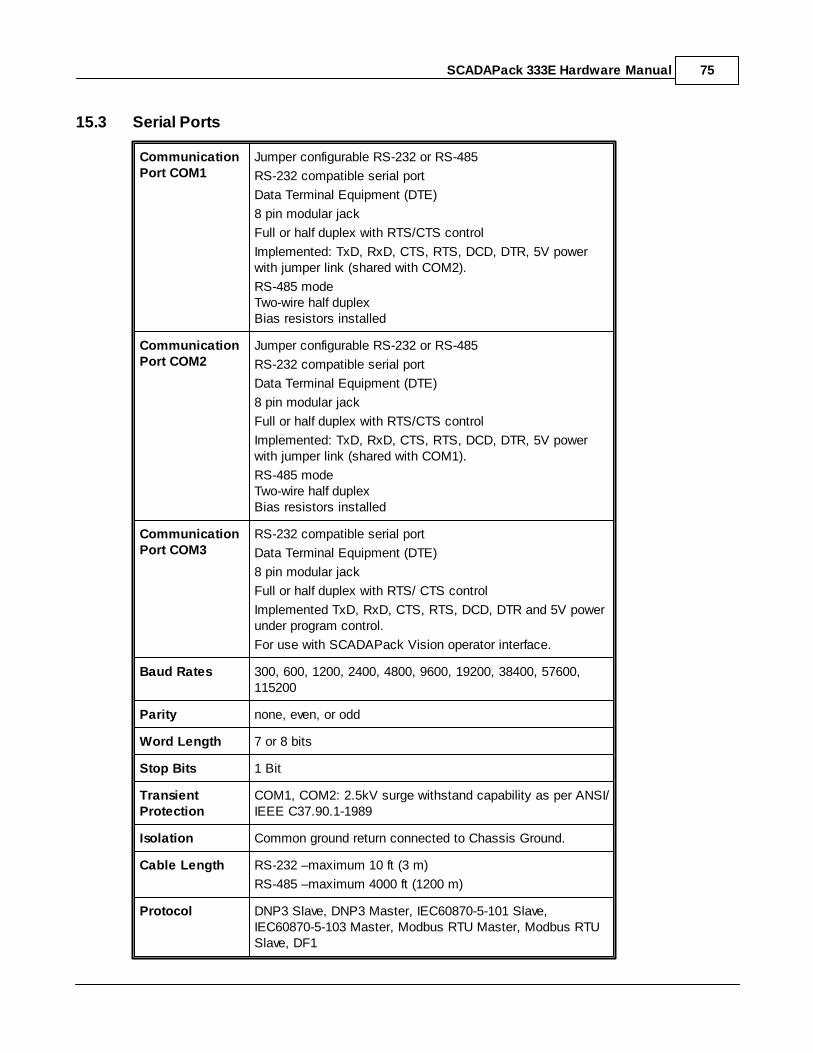
SCADAPack 333E Hardware Manual 75
15.3 Serial Ports
CommunicationPort COM1
Jumper configurable RS-232 or RS-485
RS-232 compatible serial port
Data Terminal Equipment (DTE)
8 pin modular jack
Full or half duplex with RTS/CTS control
Implemented: TxD, RxD, CTS, RTS, DCD, DTR, 5V powerwith jumper link (shared with COM2).
RS-485 mode Two-wire half duplexBias resistors installed
CommunicationPort COM2
Jumper configurable RS-232 or RS-485
RS-232 compatible serial port
Data Terminal Equipment (DTE)
8 pin modular jack
Full or half duplex with RTS/CTS control
Implemented: TxD, RxD, CTS, RTS, DCD, DTR, 5V powerwith jumper link (shared with COM1).
RS-485 mode Two-wire half duplexBias resistors installed
CommunicationPort COM3
RS-232 compatible serial port
Data Terminal Equipment (DTE)
8 pin modular jack
Full or half duplex with RTS/ CTS control
Implemented TxD, RxD, CTS, RTS, DCD, DTR and 5V powerunder program control.
For use with SCADAPack Vision operator interface.
Baud Rates 300, 600, 1200, 2400, 4800, 9600, 19200, 38400, 57600,115200
Parity none, even, or odd
Word Length 7 or 8 bits
Stop Bits 1 Bit
TransientProtection
COM1, COM2: 2.5kV surge withstand capability as per ANSI/IEEE C37.90.1-1989
Isolation Common ground return connected to Chassis Ground.
Cable Length RS-232 –maximum 10 ft (3 m)
RS-485 –maximum 4000 ft (1200 m)
Protocol DNP3 Slave, DNP3 Master, IEC60870-5-101 Slave,IEC60870-5-103 Master, Modbus RTU Master, Modbus RTUSlave, DF1

SCADAPack 333E Hardware Manual76
Protocol Modes Slave, master, master/slave, store and forward
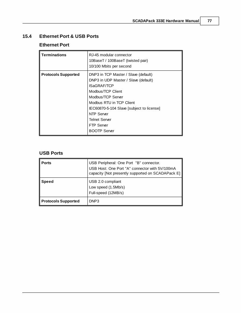
SCADAPack 333E Hardware Manual 77
15.4 Ethernet Port & USB Ports
Ethernet Port
Terminations RJ-45 modular connector
10BaseT / 100BaseT (twisted pair)
10/100 Mbits per second
Protocols Supported DNP3 in TCP Master / Slave (default)
DNP3 in UDP Master / Slave (default)
ISaGRAF/TCP
Modbus/TCP Client
Modbus/TCP Server
Modbus RTU in TCP Client
IEC60870-5-104 Slave [subject to license]
NTP Server
Telnet Server
FTP Server
BOOTP Server
USB Ports
Ports USB Peripheral: One Port "B" connector.
USB Host: One Port "A" connector with 5V/100mAcapacity [Not presently supported on SCADAPack E]
Speed USB 2.0 compliant
Low speed (1.5Mb/s)
Full-speed (12MB/s)
Protocols Supported DNP3

SCADAPack 333E Hardware Manual78
15.5 Visual Indicators
COM1 received data (RX) LED
transmitted data (TX) LED
clear to send (CTS) LED
data carrier detect (DCD) LED
COM2 received data (RX) LED
transmitted data (TX) LED
clear to send (CTS) LED
data carrier detect (DCD) LED
COM3 received data (RX) LED
transmitted data (TX) LED
clear to send (CTS) LED
data carrier detect (DCD) LED
Status Power Mode LED
Run LED
Status LED (blinking when operational non-zerostatus code present)
FORCE LED (some I/O has been locked byISaGRAF)
Counters 3 LEDs
LAN Link indicator (LINK) LEDActivity indicator (ACT.) LED
USB USB status indicator (USB STAT) LED
(under user program control)
Push-button LED power toggle
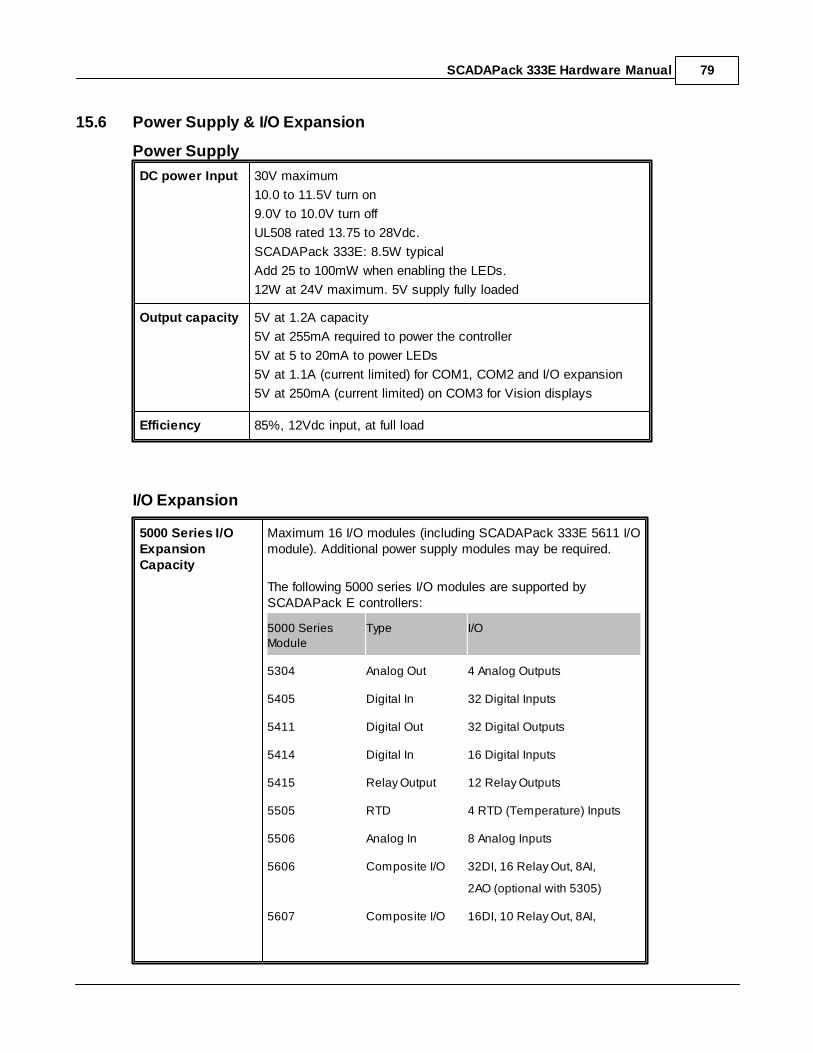
SCADAPack 333E Hardware Manual 79
15.6 Power Supply & I/O Expansion
Power Supply
DC power Input 30V maximum
10.0 to 11.5V turn on
9.0V to 10.0V turn off
UL508 rated 13.75 to 28Vdc.
SCADAPack 333E: 8.5W typical
Add 25 to 100mW when enabling the LEDs.
12W at 24V maximum. 5V supply fully loaded
Output capacity
5V at 1.2A capacity
5V at 255mA required to power the controller
5V at 5 to 20mA to power LEDs
5V at 1.1A (current limited) for COM1, COM2 and I/O expansion
5V at 250mA (current limited) on COM3 for Vision displays
Efficiency 85%, 12Vdc input, at full load
I/O Expansion
5000 Series I/OExpansionCapacity
Maximum 16 I/O modules (including SCADAPack 333E 5611 I/Omodule). Additional power supply modules may be required.
The following 5000 series I/O modules are supported bySCADAPack E controllers:
5000 SeriesModule
Type I/O
5304 Analog Out 4 Analog Outputs
5405 Digital In 32 Digital Inputs
5411 Digital Out 32 Digital Outputs
5414 Digital In 16 Digital Inputs
5415 Relay Output 12 Relay Outputs
5505 RTD 4 RTD (Temperature) Inputs
5506 Analog In 8 Analog Inputs
5606 Composite I/O 32DI, 16 Relay Out, 8AI,
2AO (optional with 5305)
5607 Composite I/O 16DI, 10 Relay Out, 8AI,

SCADAPack 333E Hardware Manual80
2AO (optional with 5305)
5608 Composite I/O 12DI, 6 Relay Out
5610 Composite I/O 16DI, 10 Relay Out
5611 Composite I/O 16DI, 10 Relay Out, 4AI,
2AO (optional with 5305)
5000
Series InputChange toDatabase Update
SCADAPack 333E Typical: 170mS
Add 20mS for each additional 5000 Series I/O Module
Database Changeto 5000 SeriesOutput Signal
Typical: 18mS
With up to 10 off 5000 Series I/O modules, Typical: 18-27mS

SCADAPack 333E Hardware Manual 81
15.7 Counter Inputs
Counter Inputs Counter 0 Digital Input Counter
Counter 1 Turbine Meter inputsCounter 2 Turbine Meter inputs
Digital Input Counter 0 Jumper Selectable maximum frequency 10Hz. or 5kHz.
Dry contact input.
Wetting current typically 5mA.
Contact closure to ground is ON.
Open input is OFF
Counter 1 and 2 Designed for use with low voltage, turbine meteroutputs.
Jumper link selectable for use with turbine meteramplifiers or dry contact closure
Counter 1 and 2Turbine MeterSensitivity
Minimum input 30mVp-p at 5-50Hz.
Minimum input 150mVp-p at 150Hz.
Minimum input 650mVp-p at 5kHz.
Minimum input 750mVp-p at 10kHz.Maximum input 4Vp-p using internal amplifier
Counter 1 and 2 DryContact
Maximum input 10Vp-p without internal amplifier.
Maximum frequency 10KHz
Transient Protection 2.5kV surge withstand capability as per ANSI/IEEEC37.90.1-1989
Isolation Common ground return connected to Chassis Ground

SCADAPack 333E Hardware Manual82
16 Approvals and Certifications
SafetyUL (cULus) listed: UL508 (Industrial Control Equipment), CSAC22.2 No.142-M1987 (Process Control Equipment)
DigitalEmissions
FCC47 Part 15, Subpart B, Class A Verification
EN61000-6-4: 2007 Electromagnetic Compatibility GenericEmission Standard Part2: Industrial Environment
C-Tick compliance. Registration number N15744
Immunity EN61000-6-2: 2005 Electromagnetic Compatibility GenericStandards Immunity for Industrial Environments
CE MarkDeclaration
This product conforms to the above Emissions and ImmunityStandards and therefore conforms with the requirements ofCouncil Directive 2004/108/EEC (as amended) relating toelectromagnetic compatibility and is eligible to bear the CE mark
The Low Voltage Directive is not applicable to this product

SCADAPack 333E Hardware Manual 83