SC733 MANUAL rc - Super Micro Computer, Inc. · 1-2 SUPER SC832/SC833 Chassis User’s Guide The...
34
1.0a ® SUPER SC832/SC833 CHASSIS USER'S GUIDE MUTE RESET !
Transcript of SC733 MANUAL rc - Super Micro Computer, Inc. · 1-2 SUPER SC832/SC833 Chassis User’s Guide The...

1.0a
®
SUPER
SC832/SC833 CHASSIS
USER'S GUIDE
MUTE RESET
! 2 1R

1-2
SUPER SC832/SC833 Chassis User’s Guide
The information in this User’s Guide has been carefully reviewed and is believed to beaccurate. The vendor assumes no responsibility for any inaccuracies that may becontained in this document, makes no commitment to update or to keep current theinformation in this manual, or to notify any person or organization of the updates. PleaseNote: For the most up-to-date version of this manual, please see ourweb site at www.supermicro.com.
SUPERMICRO COMPUTER reserves the right to make changes to the product described inthis manual at any time and without notice. This product, including software, if any, anddocumentation may not, in whole or in part, be copied, photocopied, reproduced, translatedor reduced to any medium or machine without prior written consent.
IN NO EVENT WILL SUPERMICRO COMPUTER BE LIABLE FOR DIRECT, INDIRECT,SPECIAL, INCIDENTAL, OR CONSEQUENTIAL DAMAGES ARISING FROM THE USE ORINABILITY TO USE THIS PRODUCT OR DOCUMENTATION, EVEN IF ADVISED OF THEPOSSIBILITY OF SUCH DAMAGES. IN PARTICULAR, THE VENDOR SHALL NOT HAVELIABILITY FOR ANY HARDWARE, SOFTWARE, OR DATA STORED OR USED WITH THEPRODUCT, INCLUDING THE COSTS OF REPAIRING, REPLACING, INTEGRATING,INSTALLING OR RECOVERING SUCH HARDWARE, SOFTWARE, OR DATA.
Any disputes arising between manufacturer and customer shall be governed by the laws ofSanta Clara County in the State of California, USA. The State of California, County ofSanta Clara shall be the exclusive venue for the resolution of any such disputes.Supermicro's total liability for all claims will not exceed the price paid for the hardwareproduct.
Unless you request and receive written permission from SUPER MICRO COMPUTER, youmay not copy any part of this document.
Information in this document is subject to change without notice. Other products andcompanies referred to herein are trademarks or registered trademarks of their respectivecompanies or mark holders.
Copyright © 2004 by SUPER MICRO COMPUTER INC.All rights reserved.Printed in the United States of America
1-3
Chapter 1: Safety Information and Technical Specifications
Table of Contents
Chapter I: Safety Information and Technical Specifications .......... 1-4
1-1. Electrical Safety Guidelines ............................................................. 1-4
1-2. General Safety Guidelines ............................................................... 1-5
1-3. ESD Safety Guidelines ....................................................................... 1-6
1-4. Operation Safety Guidelines .......................................................... 1-6
1-5. Product Compliance Information ................................................. 1-8
1-6. Packing List and the SC832/SC833 Specifications ............... 1-9
Chapter 2: Chassis Description and Installation Procedures ........ 2-1
2-1. Chassis Description ........................................................................... 2-1
A. Contents of the Accessory Kit ............................................................... 2-1
B. Chassis Front View and the Front Control Panel ................................ 2-2
C. Chassis Rear View and the Back Panel .............................................. 2-4
2-2. Chassis Installation ........................................................................... 2-6
A. Important Safety Guidelines ..................................................................... 2-6
B. Tools Needed .............................................................................................. 2-6
C. Accessing the SCA Drive Tray and Installing a HDD .......................... 2-7
D. Removing the Top Cover of the Chassis ............................................... 2-8
E. Accessing the Front Chassis Fans ........................................................ 2-9
F. Accessing the Power Supply ................................................................ 2-10
G. Installing the Air Shrouds ....................................................................... 2-13
H. Installing the Motherboard ...................................................................... 2-15
I. Installing Chassis Rails ............................................................................ 2-17
J. Rack Installation ....................................................................................... 2-19

1-4
SUPER SC832/SC833 Chassis User’s Guide
Chapter 1-Safety Information and TechnicalSpecifications
1-1 Electrical Safety Guidelines
Warning: To avoid electrical shock, check the power
cords as follows:
Checking the Power Cords
Use the exact type of power cords as required.
Be sure to use power cord(s) that came with safety certifications.
The power cord(s) must be compliant with the AC voltage requirements in your
region.
The power cord plug cap must have an electrical current rating that is at least
125% of the electrical current rating of this product.
The power cord plug cap that plugs into the AC receptacle on the power
supply must be an IEC 320, sheet C13, type female connector.
Be sure to disconnect the power supply before accessing the SC832/SC833
or its components.
Plug the Power cord(s) into a socket that is properly grounded before
turning on the power.
Warning: Follow the guidelines below to avoid possible
damages to the system or injury to yourself:
General Electrical Safety Guidelines
Be aware of the locations of the power switches on the chassis and in the
room, so you can disconnect the power supply if an accident occurs.
Take extra precautionary measures when working with high voltage
components. It is not recommended to work alone.
Before removing or installing main system components, be sue to disconnect
the power first. Turn off the system before you disconnect the PS.
Use only one hand when working with powered-on electrical equipment to
avoid possible electrical shock.

1-5
Chapter 1: Safety Information and Technical Specifications
Use rubber mats specifically designed as electrical insulators when working
with computer systems.
The power supply or power cord must include a grounding plug and must
be plugged into grounded outlets.
Motherboard Battery: CAUTION -Make sure not to install the onboard battery
upside down to avoid possible explosion. Make sure that the positive side
should be facing up on the motherboard. This battery must be replaced
only with the same or an equivalent type recommended by the manufac-
turer. Dispose of used batteries according to the manufacturer's instruc-
tions.
CD-ROM Laser: CAUTION - Do not open the enclosures of power supplies
or CD ROM to avoid injury.
1-2 General Safety Guidelines
Warning: Follow these rules to ensure general safety:
Keep the area around the SC832/SC833 clean and free of clutter.
To avoid injuries to the back, be sure to use your leg muscles, keep your
back straight, and bend your knees, when lifting the system.
Avoid wearing loose clothing to preventing it from coming into contact with
After removing the components or chassis covers from the system, place
them on a table for safeguard.
Be sure to remove any jewelry or metal objects before working on the
chassis to avoid short circuits should these objects come into contact
with power circuits.
After accessing the interior of the chassis, be sure to close the chassis
with chassis covers and secure the chassis to the racks with screws.

1-6
SUPER SC832/SC833 Chassis User’s Guide
1-3 ESD Safety Guidelines
Use a grounded wrist strap designed to prevent static discharge.
Keep all components and printed circuit boards (PCBs) in their antistatic
bags until ready for use.
Touch a grounded metal object before removing the board from the antistatic bag.
Do not let components or PCBs come into contact with your clothing, which may
retain a charge even if you are wearing a wrist strap.
Touch a grounded metal object before removing the board from the antistatic
bag.
Handle a board by its edges only; do not touch its components, peripheral
chips, memory modules or contacts.
When handling chips or modules, avoid touching their pins.
Put the motherboard and peripherals back into their antistatic bags when not in
use.
For grounding purposes, make sure your computer chassis provides excel
lent conductivity between the power supply, the case, the mounting
fasteners and the motherboard.
Electric Static Discharge (ESD) can damage electronic com-
ponents. To prevent damage to your system board, it is
important to handle it very carefully. The following measures are
generally sufficient to protect your equipment from ESD.
1-4 Operation Safety Guidelines
Warning: For proper cooling, make sure to install all
chassis covers before turning on the system. If this rule is
not strictly followed, warranty may become void. Do not openthe casing of a power supply. Power supplies can only be
accessed and serviced by a qualified technician of the manufacturer.
1-7
Chapter 1: Safety Information and Technical Specifications
To avoid personal injury and property damage, please carefully
follow all the safety steps listed below:
Before accessing the chassis:
1. Turn off all peripheral devices connected to the SC832/SC833.
2. Press the power button to power off the system.
3. Unplug all power cords from the system or the wall outlets.
4. Disconnect all the cables and label the cables for easy identification.
5. Use a grounded wrist strap designed to prevent static discharge when
handling components.
Removing the chassis covers:
After completing the above steps, you can remove the covers and install
components/peripheral devices into the chassis as described in Chapter 2.
1. Unlock and remove the screws and fasteners to remove the cover or
components.
2. Save all the screws and fasteners for later use. (If necessary, label these
screws or fasteners for easy identification.)
3. Follow the instruction given in Chapter 3 to remove the chassis covers.
Reinstalling the chassis covers:
To maintain proper system cooling and airflow, do not operate the system
without installing all chassis covers back to the chassis. To reinstall the chassis
covers, please follow the steps listed below:
1. Make sure that all components and devices are securely fastened
on the chassis and there are no loose parts/screws inside the chassis.
2. Make sure that all cables are properly connected to the connectors and ports.
3. Use the original screws or fasteners to install the covers to the chassis.
4. Be sure to lock to the chassis or the system to prevent unauthorized access.5. For proper cooling, enclose the chassis with covers before operating the
system.

1-8
SUPER SC832/SC833 Chassis User’s Guide
Before installing the chassis into a rack:
1. Make sure that the rack is securely anchored onto a unmovable surface or
structure before installing the chassis into the rack.
2. Unplug the power cord(s) of the rack before installing the chassis into the
rack.
3. Make sure that the system is adequately supported. Make sure that all the
components are securely fastened to the chassis toprevent components fall-
ing off from the chassis.
4. Be sure to install an AC Power Disconnect for the entire rack assembly and
this Power Disconnect must be clearly marked.
5. The rack assembly shall be properly grounded to avoid electric shock.
6. The rack assembly must provide sufficient airflow to the chassis for proper
cooling.
1-5 Product Compliance InformationThe SC832/SC833 Chassis is compliant with the following safetystandards/requirements:
Product Safety
*Canada/USA--UL60 950-CSA60 950
*European Union--EN 60 950
*International--IEC 60 950
Electromagnetic Compatibility (EMC)-Emissions *European Union--EN55022: 1994
*International--CISPR 22
*USA--Title 47 CFR, Part 15
Power Line Harmonics/Voltage Flicker *European Union--EN61000-3-2/EN61000-3-3 *International--IEC61000-3-2
Electromagnetic Compatibility-Immunity*European Union--EN55024: 1998
*International--CISPR 24

1-9
Chapter 1: Safety Information and Technical Specifications
A. The SC832/SC833 chassis contains the following:
The SC832 chassis:
1-6 Packing List and the SC832/SC833 Specifications
��������� ���� �� ����������
����������� ���� �� ����� ������
������������ ��!�����"�#� $� "�%�&&'��
�&���(����!�����)�#� * ��#�+� "�%�&&'��
�,�� +��(�-.#-�#��/'&0�������. +�� �� �0��&&1&2��3/'&0��
������. +����������4.��� �� ����� �����������3/'&0��
11&0�������. +�� �� �0��&&$/��311&0��
�� ����� ����56 +�#����3����� �*#+��� �� ������ ������
�� ������7���56 +�#����3�������*#+��� �� �������������
"+� ������ �� "��� �������
���(*2������ * ��#�+� ��2� �����$����
�
�
�
�
�
��������� ���� �� ����������
����������� ���� �� ����� ������
������������ ��!�����"�#� $� "�%�&&'$�
�&���(����!�����)�#� �� "�%�&&'��
�� ����� $$�"�#��!�.-������
�� ����� $1�
�,�� +��(�-.#-�#��/'&0�������. +�� �� �0��&&1&2��3/'&0��
������. +����������4.��� �� ����� �����������3/'&0��
11&0�������. +�� �� �0��&&$/��311&0��
�� ����� ����56 +�#����3����� �*#+��� �� ������ ������
�� ������7���56 +�#����3�������*#+��� �� �������������
"+� ������ �� "��� �������
���(*2������ * ��#�+� ��2� �����$����
�
The SC833 chassis:
1-10
SUPER SC832/SC833 Chassis User’s Guide
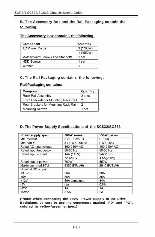
D. The Power Supply Specifications of the SC832/SC833
The Accessory box contains the following:
C. The Rail Packaging contains the following:
Rail Packaging contains:
B. The Accessory Box and the Rail Packaging contain thefollowing:
Power supply spec 760W series
550W Series
Mfr. model# 3 x SP382-TS SP550 Mfr. part # 3 x PWS-0050M PWS-0047 Rated AC input voltage
100-240V AC
100-240V AC
Rated input frequency 50-60 Hz 50-60 Hz Rated input current
14A (115V)
9A(115V) 7A (230V) 4.5A(230V) Rated output power
760W
550W Maximum rated BTU
4350 BTUs/Hr
2910 BUTs/Hr Nominal DC output +3.3V
36A
30A +5V
36A
35A +12V
50A combined
34A -5V
n/a
0.8A -12V
1A
1A +5Vsb 3.5A 2A
(*Note: When connecting the 760W Power Supply to the DriveBackplane, be sure to use the connectors marked "PD" and "PG",colored in yellow/green stripes.)
��������� ���� ��
(�56�(�+������4+�� �������
"�#����56����)��2�.#�#8�(�56�(�+� ��
(�����56����)��2�.#�#8�(�56�(�+� ��
2�.#�#8��5���� ������
��������� ���� ��
���3/'&0������������-��
���311&0��
2��!�4��-��5�����#-����#-�))�� ������
�����5���� ������
0�#5!� ��
1-11
Chapter 1: Safety Information and Technical Specifications
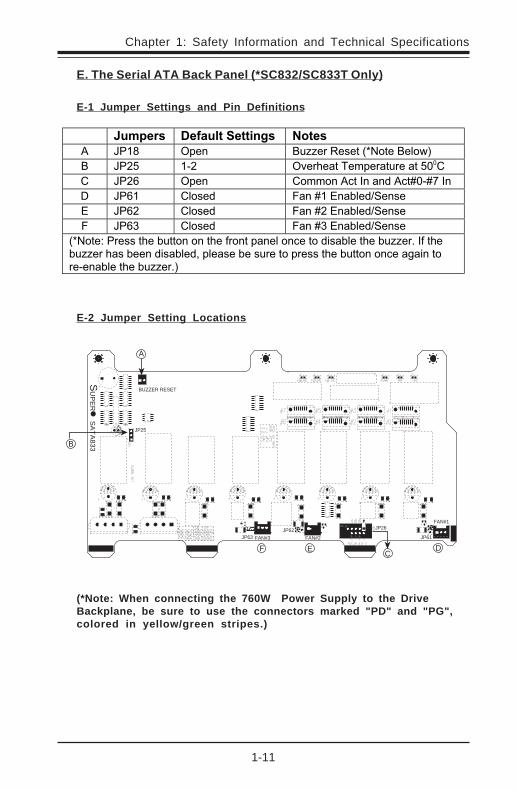
E. The Serial ATA Back Panel (*SC832/SC833T Only)
E-1 Jumper Settings and Pin Definitions
E-2 Jumper Setting Locations
A
B
F E CD
BUZZER RESET
JP25
FAN#3JP63 FAN#2
JP26FAN#1
JP61JP62
SU
PE
R S
ATA
833
(*Note: When connecting the 760W Power Supply to the DriveBackplane, be sure to use the connectors marked "PD" and "PG",colored in yellow/green stripes.)
������� ����������� ��� �����
�� 9����� * �#�� �.::��(������3%������+����
�� 9��1�� ����� *��!���� �� ���.�����1&&��
�� 9��'�� * �#�� �����#��5��7#��#-��5�;&�;/�7#�
�� 9�'��� �+���-� "�#�;���#�4+�-<��#���
�� 9�'��� �+���-� "�#�;���#�4+�-<��#���
"� 9�'��� �+���-� "�#�;���#�4+�-<��#���
�3%���=�������!��4.���#��#��!��)�#�� �#�+��#5�����-��4+���!��4.::�>�7)��!��4.::��!���4��#�-��4+�-?� +�����4���.����� �����!��4.���#��#5���8�#�������#�4+���!��4.::�>�
�

1-12
SUPER SC832/SC833 Chassis User’s Guide
F. The SCSI Back Panel (*SC832/SC833S Only)
F-1 Jumper Settings and Pin Definitions
F-2 Jumper Setting Locations
A
D C B
BUZZER RESET
FAN#3JP43
FAN#2JP42
FAN#1JP41
SUPER SCA833S
(*Note: When connecting the 760W Power Supply to the DriveBackplane, be sure to use the connectors marked "PD" and "PG",colored in yellow/green stripes.)
������� ����������� ��� �����
�� 9����� * �#�� �.::��(������3%������+����
�� 9�$��� �+���-� "�#�;��*#<��#���
�� 9�$��� �+���-� "�#�;��*#<��#���
�� 9�$��� �+���-� "�#�;��*#<��#���
�3%���=�������!��4.���#��#��!��)�#�� �#�+��#5�����-��4+���!��4.::�>�7)��!��4.::��!���4��#�-��4+�-?� +�����4���.����� �����!��4.���#��#5���8�#�������#�4+���!��4.::�>�
�
1-13
Chapter 1: Safety Information and Technical Specifications
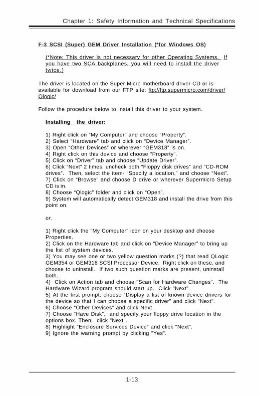
F-3 SCSI (Super) GEM Driver Installation (*for Windows OS)
(*Note: This driver is not necessary for other Operating Systems. Ifyou have two SCA backplanes, you will need to install the drivertwice.)
The driver is located on the Super Micro motherboard driver CD or isavailable for download from our FTP site: ftp://ftp.supermicro.com/driver/Qlogic/
Follow the procedure below to install this driver to your system.
Installing the driver:
1) Right click on “My Computer” and choose “Property”.2) Select “Hardware” tab and click on “Device Manager”.3) Open “Other Devices” or wherever “GEM318” is on.4) Right click on this device and choose “Property”.5) Click on “Driver” tab and choose “Update Driver”.6) Click “Next” 2 times, uncheck both “Floppy disk drives” and “CD-ROMdrives”. Then, select the item- “Specify a location,” and choose “Next”.7) Click on “Browse” and choose D drive or wherever Supermicro SetupCD is in.8) Choose “Qlogic” folder and click on “Open”.9) System will automatically detect GEM318 and install the drive from thispoint on.
or,
1) Right click the "My Computer" icon on your desktop and chooseProperties.2) Click on the Hardware tab and click on "Device Manager" to bring upthe list of system devices.3) You may see one or two yellow question marks (?) that read QLogicGEM354 or GEM318 SCSI Processor Device. Right click on these, andchoose to uninstall. If two such question marks are present, uninstallboth.4) Click on Action tab and choose "Scan for Hardware Changes". TheHardware Wizard program should start up. Click "Next".5) At the first prompt, choose “Display a list of known device drivers forthe device so that I can choose a specific driver” and click "Next".6) Choose “Other Devices” and click Next.7) Choose “Have Disk”, and specify your floppy drive location in theoptions box. Then, click "Next".8) Highlight “Enclosure Services Device” and click "Next".9) Ignore the warning prompt by clicking "Yes".

1-14
SUPER SC832/SC833 Chassis User’s Guide
Notes

2-1
Chapter 2: Chassis Description and Installation Instructions
2-1 Chassis Description
A. Contents of the Accessory Kit:
The following items are included in the Accessory Kit:
Chapter 2: Chassis Description and InstallationInstructions
G H
F
F. Flat head M4 x 4 mm [0.157]
RAIL
I
G. Round head M4 x 4 mm [0.157]
H. Flat head M5 x 12 mm [0.472]
I. Washer for M5
B
B. Flat head 6-32 x 5 mm [0.197]
DRIVE
D E
E. Round head M3 x 5 mm [0.197]
D. Pan head 6-32 x 5 mm [0.197]
A
A. Pan head w/ lock 6-32 x 4.5 mm [0.177]
M/B
B
B. Flat head 6-32 x 5 mm [0.197]
HDD
C
C. Thumb screw 6-32 x 5 mm [0.197]
J
J. M/B standoff, 6-32 to 6-32
M/B STANDOFF
K
K. M/B (CPU) standoff, M5 to 6-32
2-2
SUPER SC832/SC833 Chassis User’s Guide
MUTE RESET
! 2 1R
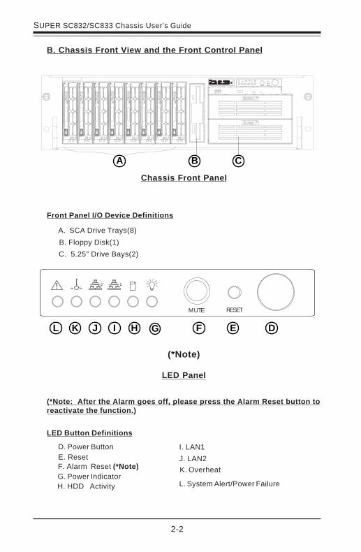
B. Chassis Front View and the Front Control Panel
LED Panel
LED Button Definitions
L. System Alert/Power Failure
K. Overheat
J. LAN2
I. LAN1
H. HDD ActivityG. Power IndicatorF. Alarm Reset (*Note)
E. ResetD. Power Button
Chassis Front Panel
A. SCA Drive Trays(8)
B. Floppy Disk(1)
Front Panel I/O Device Definitions
C. 5.25" Drive Bays(2)
A B C
DEFGHIJKL
(*Note: After the Alarm goes off, please press the Alarm Reset button toreactivate the function.)
(*Note)
! 2 1
MUTE RESET
2-3
Chapter 2: Chassis Description and Installation Instructions
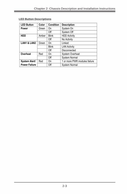
LED Button Descriptions
��������� ����� ���� � �� ����� �� ��
@��#� *#� �������*#������
� *))�� �������*))�
��4�� �+#6� �����5����� ��
� *))� %���5�����
@��#� *#� A#6�-�
� �+#6� A�%��5�����
�!�"#�!�$
� *))� ��5�##�5��-�
(�-� *#� �������*��!����%&��'���
� *))� �������%���+�
(�-� *#� ���������0(���-.+���)�+.��������!����(
�����)� ���� � *))�� �������%���+��
2-4
SUPER SC832/SC833 Chassis User’s Guide
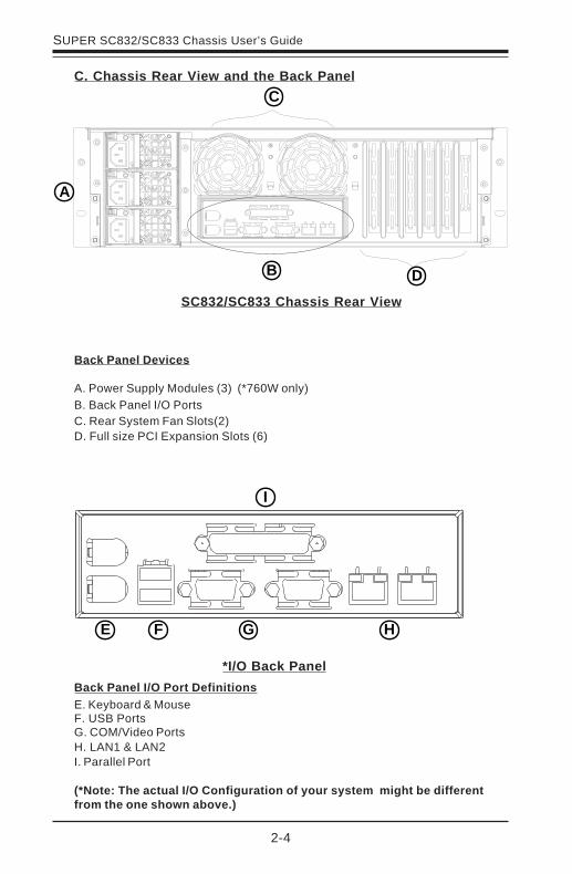
C. Chassis Rear View and the Back Panel
*I/O Back Panel
Back Panel I/O Port DefinitionsE. Keyboard & Mouse
SC832/SC833 Chassis Rear View
Back Panel Devices
A. Power Supply Modules (3) (*760W only)B. Back Panel I/O PortsC. Rear System Fan Slots(2)
F. USB PortsG. COM/Video PortsH. LAN1 & LAN2I. Parallel Port
(*Note: The actual I/O Configuration of your system might be differentfrom the one shown above.)
A
B
C
D
D. Full size PCI Expansion Slots (6)
I
E F G H
2-5
Chapter 2: Chassis Description and Installation Instructions
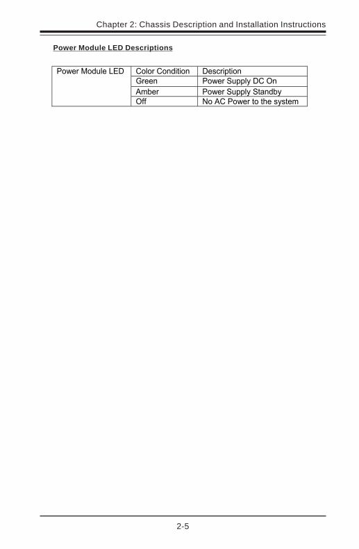
Power Module LED Descriptions
��+����#-��#� ���5 ��#�
@��#� ������. +�����*#��
��4�� ������. +�����#-4��
�����2�-.+��A���
*))� %��������������!���������

2-6
SUPER SC832/SC833 Chassis User’s Guide
B. Tools needed
2-2 Chassis Installation
A. Important Safety Guidelines
StopThis product shall only be accessed, assembled and serviced
by technically qualified personnel or technicians.
To avoid personal injury and property damage, please read all the information
provided in Chapter 1, and carefully follow all the Safety Guidelines listed before
accessing or servicing the SC832/SC833 or its components. For your convenience,
some Safety Steps are also listed below:
Safety Steps
Before accessing the chassis:1. Turn off all peripheral devices and turn off the power supply connected to the
SC832/SC833.
2. Unplug all power cords from the system or the wall outlets.
3. Disconnect all the cables and label the cables for easy identification.
4. Use a grounded wrist strap designed to prevent static discharge when han-
dling components.
Removing the chassis covers:
After completing the above steps, you can remove the chassis covers and install
components and devices into the chassis as described in this chapter.
1. Unlock and remove the screws and fasteners to remove the cover or components.
2. Save all the screws and fasteners for later use. (If necessary, label these screws
or fasteners for easy identification.)
3. Follow the instructions given in this chapter to remove the chassis covers.
1. Fillips Screw Driver2. Antistatic Strap
2-7
Chapter 2: Chassis Description and Installation Instructions
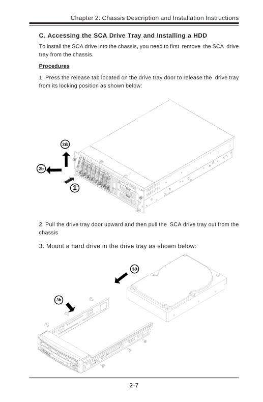
C. Accessing the SCA Drive Tray and Installing a HDD
To install the SCA drive into the chassis, you need to first remove the SCA drive
tray from the chassis.
Procedures
1. Press the release tab located on the drive tray door to release the drive tray
from its locking position as shown below:
2. Pull the drive tray door upward and then pull the SCA drive tray out from the
chassis.
3. Mount a hard drive in the drive tray as shown below:
1
2a
2b
3a
3b
2-8
SUPER SC832/SC833 Chassis User’s Guide
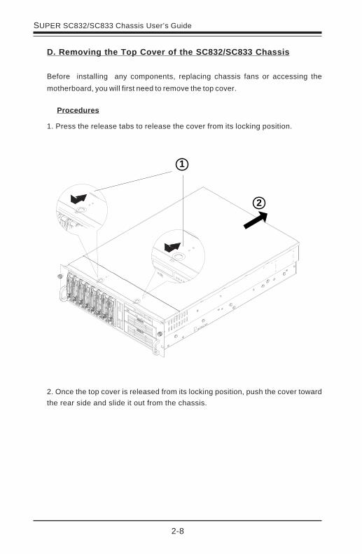
D. Removing the Top Cover of the SC832/SC833 Chassis
Before installing any components, replacing chassis fans or accessing the
motherboard, you will first need to remove the top cover.
Procedures
1. Press the release tabs to release the cover from its locking position.
2. Once the top cover is released from its locking position, push the cover toward
the rear side and slide it out from the chassis.
2
1

2-9
Chapter 2: Chassis Description and Installation Instructions
E. Accessing the Front Chassis Fans
Procedures
1. Press the release tab located on the left side of the front chassis fan (when
facing the front side of the fan) to release the chassis fan from its locking
position as shown in the picture below:
2. Once you've loosened the front chassis fan, you can pull the fan out.
1
2
2-10
SUPER SC832/SC833 Chassis User’s Guide
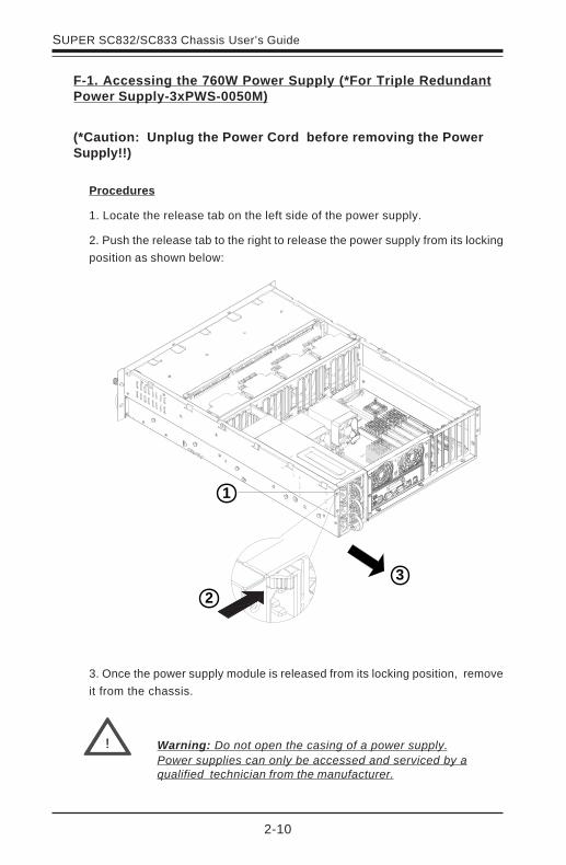
F-1. Accessing the 760W Power Supply (*For Triple RedundantPower Supply-3xPWS-0050M)
Procedures
1. Locate the release tab on the left side of the power supply.
2. Push the release tab to the right to release the power supply from its locking
position as shown below:
3. Once the power supply module is released from its locking position, remove
it from the chassis.
Warning: Do not open the casing of a power supply.Power supplies can only be accessed and serviced by aqualified technician from the manufacturer.
!
(*Caution: Unplug the Power Cord before removing the PowerSupply!!)
1
2
3

2-11
Chapter 2: Chassis Description and Installation Instructions
F-2. Accessing the 550W-Power Supply (*For Single PWS-0047)
Procedures
1. Unscrew the screws to remove the metal plate.
2. Remove the four screws from the power supply.
3. Pull the power supply out from its housing as shown in the picture:
(PWS-0047)
(*Caution: Unplug the Power Cord before removing the PowerSupply!!)
21
3
2-12
SUPER SC832/SC833 Chassis User’s Guide
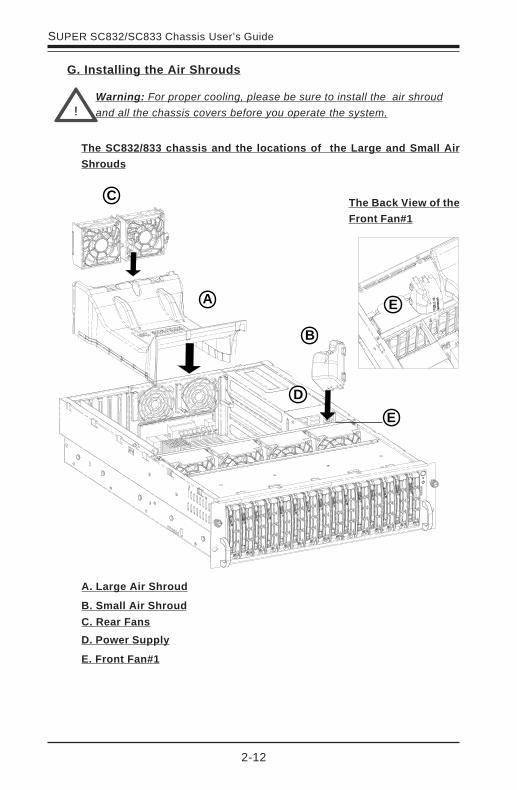
!Warning: For proper cooling, please be sure to install the air shroud
and all the chassis covers before you operate the system.
G. Installing the Air Shrouds
AAa
The SC832/833 chassis and the locations of the Large and Small Air
Shrouds
A
B
C
D
E
E
A. Large Air Shroud
B. Small Air Shroud
C. Rear Fans
D. Power Supply
E. Front Fan#1
The Back View of the
Front Fan#1
2-13
Chapter 2: Chassis Description and Installation Instructions
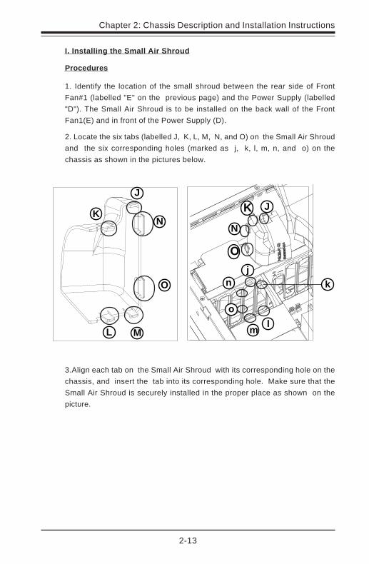
Procedures
2. Locate the six tabs (labelled J, K, L, M, N, and O) on the Small Air Shroud
and the six corresponding holes (marked as j, k, l, m, n, and o) on the
chassis as shown in the pictures below.
I. Installing the Small Air Shroud
3.Align each tab on the Small Air Shroud with its corresponding hole on the
chassis, and insert the tab into its corresponding hole. Make sure that the
Small Air Shroud is securely installed in the proper place as shown on the
picture.
J
K
L M
N
O
j
k
lm
n
o
1. Identify the location of the small shroud between the rear side of Front
Fan#1 (labelled "E" on the previous page) and the Power Supply (labelled
"D"). The Small Air Shroud is to be installed on the back wall of the Front
Fan1(E) and in front of the Power Supply (D).
JK
N
O

2-14
SUPER SC832/SC833 Chassis User’s Guide
II. Installing the Large Air Shroud
Procedures
1. Remove all the rear fans from the chassis if you have not done so. You can
remove a rear fan from the chassis by pressing the release tab on the upper
right corner of the fan and pulling the fan out of the chassis.
2. Align the Large Air Shroud against the rear fan stem (labelled 2) and gently
push the air shroud into the chassis.
3. Slide the rear fans into the fan slots. Make sure that the fans are securely
fastened on the chassis.
2

2-15
Chapter 2: Chassis Description and Installation Instructions
H. Installing the Motherboard
Be sue to disconnect the power supply before accessing or installing the mother-board into the chassis. However, you will need to, first, identify the CPU locations,and then, install the correct type of standoffs under the CPUs before installing themotherboard into the chassis. (Refer to Chapter 1 for Safety Guidelines.)
Procedures
1. Lay the chassis on a flat surface. Locate the CPU mounting holes on the
chassis and install CPU standoffs on the chassis.
(**Note: the motherboard shown above is for reference only!! The motherboardis not included in the SC832/SC833 shipping package.)
1
2-16
SUPER SC832/SC833 Chassis User’s Guide
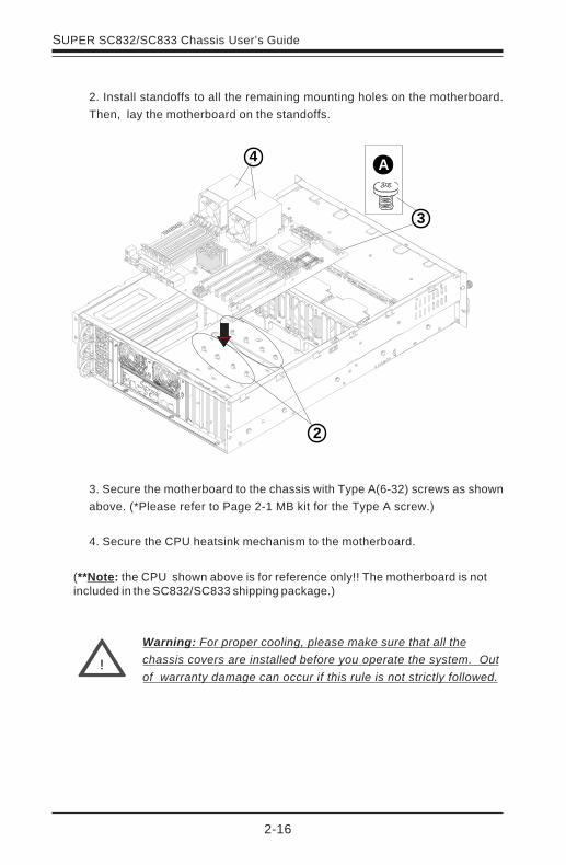
3. Secure the motherboard to the chassis with Type A(6-32) screws as shown
above. (*Please refer to Page 2-1 MB kit for the Type A screw.)
4. Secure the CPU heatsink mechanism to the motherboard.
2. Install standoffs to all the remaining mounting holes on the motherboard.
Then, lay the motherboard on the standoffs.
Warning: For proper cooling, please make sure that all the
chassis covers are installed before you operate the system. Out
of warranty damage can occur if this rule is not strictly followed.!
2
A
3
4
(**Note: the CPU shown above is for reference only!! The motherboard is notincluded in the SC832/SC833 shipping package.)

2-17
Chapter 2: Chassis Description and Installation Instructions
Press the Locking Tab
I. Installing Chassis Rails
Please make sure that the chassis covers and chassis rails are installed on thechassis before you install the chassis into the rack.
Procedures to Install Chassis Rails
2. Press the locking tab to release the inner rail from its locking position andpull out the inner rail from the rail assembly. (*The inner rails are to be attachedto the chassis and the outer rails are to be installed in the rack.)
Outer rail (to be installed in therack)
Pull out the Innerrail (to beattached on thechassis)
1. Included in the shipping package are a pair of rail assemblies. In each railassembly, locate the inner rail and the outer rail.
Before installing the Chassis rails:
1. Enclose the chassis with chassis covers.
2. Unplug the AC power cord(s).
3. Remove all external devices and connectors.
To avoid personal injury and property damage, please carefully
follow all the safety steps listed below:
2-18
SUPER SC832/SC833 Chassis User’s Guide
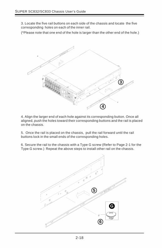
3. Locate the five rail buttons on each side of the chassis and locate the fivecorresponding holes on each of the inner rail.
4. Align the larger end of each hole against its corresponding button. Once allaligned, push the holes toward their corresponding buttons and the rail is placedon the chassis.
5. Once the rail is placed on the chassis, pull the rail forward until the railbuttons lock in the small ends of the corresponding holes.
6. Secure the rail to the chassis with a Type G screw (Refer to Page 2-1 for theType G screw.) Repeat the above steps to install other rail on the chassis.
3
(*Please note that one end of the hole is larger than the other end of the hole.)
4
5
6
G
2-19
Chapter 2: Chassis Description and Installation Instructions
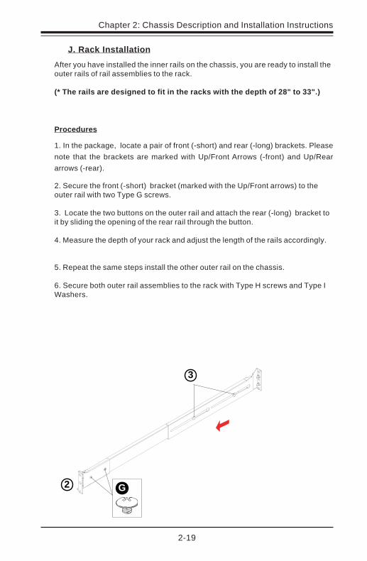
J. Rack Installation
After you have installed the inner rails on the chassis, you are ready to install theouter rails of rail assemblies to the rack.
(* The rails are designed to fit in the racks with the depth of 28" to 33".)
Procedures
1. In the package, locate a pair of front (-short) and rear (-long) brackets. Please
note that the brackets are marked with Up/Front Arrows (-front) and Up/Rear
arrows (-rear).
2. Secure the front (-short) bracket (marked with the Up/Front arrows) to theouter rail with two Type G screws.
3. Locate the two buttons on the outer rail and attach the rear (-long) bracket toit by sliding the opening of the rear rail through the button.
4. Measure the depth of your rack and adjust the length of the rails accordingly.
5. Repeat the same steps install the other outer rail on the chassis.
6. Secure both outer rail assemblies to the rack with Type H screws and Type IWashers.
2
3
G

2-20
SUPER SC832/SC833 Chassis User’s Guide
7. Slide the SC832/SC833 chassis into the rack as shown below:
(The SC832/SC833 may not slide into the rack smoothly or easily when installed
the first time. However, some adjustment to the slide assemblies might be needed
for easy installation.)
8. You will need to release the safety taps on both sides of the chassis in order
to completely remove the chassis out of the rack.