sc200 Controller - Hach Flow · PDF filesc200 Controller 08/2013, Edition 6 ... omission in...
50
DOC023.53.80040 sc200 Controller 08/2013, Edition 6 User Manual
-
Upload
trinhkhanh -
Category
Documents
-
view
227 -
download
1
Transcript of sc200 Controller - Hach Flow · PDF filesc200 Controller 08/2013, Edition 6 ... omission in...

DOC023.53.80040
sc200 Controller08/2013, Edition 6
User Manual

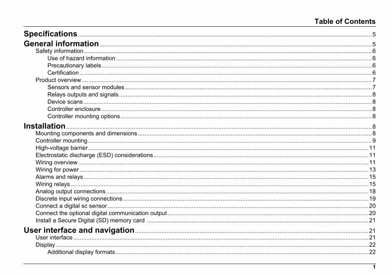
Table of ContentsSpecifications ..................................................................................................................................................................................5
General information .....................................................................................................................................................................5Safety information..............................................................................................................................................................................6
Use of hazard information...........................................................................................................................................................6Precautionary labels ...................................................................................................................................................................6Certification.................................................................................................................................................................................6
Product overview...............................................................................................................................................................................7Sensors and sensor modules.....................................................................................................................................................7Relays outputs and signals .........................................................................................................................................................8Device scans..............................................................................................................................................................................8Controller enclosure....................................................................................................................................................................8Controller mounting options........................................................................................................................................................8
Installation .........................................................................................................................................................................................8Mounting components and dimensions.............................................................................................................................................8Controller mounting............................................................................................................................................................................9High-voltage barrier .........................................................................................................................................................................11Electrostatic discharge (ESD) considerations..................................................................................................................................11Wiring overview................................................................................................................................................................................11Wiring for power ...............................................................................................................................................................................13Alarms and relays............................................................................................................................................................................15Wiring relays....................................................................................................................................................................................15Analog output connections...............................................................................................................................................................18Discrete input wiring connections....................................................................................................................................................19Connect a digital sc sensor ..............................................................................................................................................................20Connect the optional digital communication output .........................................................................................................................20Install a Secure Digital (SD) memory card ......................................................................................................................................21
User interface and navigation .............................................................................................................................................21User interface...................................................................................................................................................................................21Display.............................................................................................................................................................................................22
Additional display formats .........................................................................................................................................................22
1

Graphical display......................................................................................................................................................................22
System startup ..............................................................................................................................................................................23Set the language, date and time for the first time ...........................................................................................................................23Controller configuration information.................................................................................................................................................23
Advanced operation ..................................................................................................................................................................24Security setup..................................................................................................................................................................................24
Enable or disable the passcode................................................................................................................................................24Edit the passcode.....................................................................................................................................................................24Protect features........................................................................................................................................................................25
Configure a 4-20 mA input module ..................................................................................................................................................25Configure a 4-20 mA output module ................................................................................................................................................25Configure the controller analog outputs ...........................................................................................................................................26
Logarithmic output mode .........................................................................................................................................................28Bilinear output mode.................................................................................................................................................................28
Configure relays...............................................................................................................................................................................28Display setup...................................................................................................................................................................................36Update the date and time.................................................................................................................................................................36Set the datalog mode and interval ...................................................................................................................................................37Set up a calculation..........................................................................................................................................................................37Set up the discrete inputs ................................................................................................................................................................37Update the display language...........................................................................................................................................................38Using the secure digital memory (SD) card.....................................................................................................................................38
Updating software.....................................................................................................................................................................39Saving data and event logs with SD cards...............................................................................................................................39Access data and event log files on the SD card.......................................................................................................................40Firmware updates with SD cards..............................................................................................................................................40Backup settings to an SD card.................................................................................................................................................40Restore settings to the controller ..............................................................................................................................................41Transfer settings to another device..........................................................................................................................................41
Using the service port ......................................................................................................................................................................41Using DataCom................................................................................................................................................................................41
Table of Contents
2

Maintenance ...................................................................................................................................................................................42Cleaning the controller .....................................................................................................................................................................42Fuse replacement ............................................................................................................................................................................42Battery replacement .........................................................................................................................................................................42
Troubleshooting ..........................................................................................................................................................................42Test and Maintenance menu...........................................................................................................................................................44Warning and error conditions...........................................................................................................................................................45
Device scan information .......................................................................................................................................................45
Replacement parts and accessories ...............................................................................................................................45
Table of Contents
3

Table of Contents
4
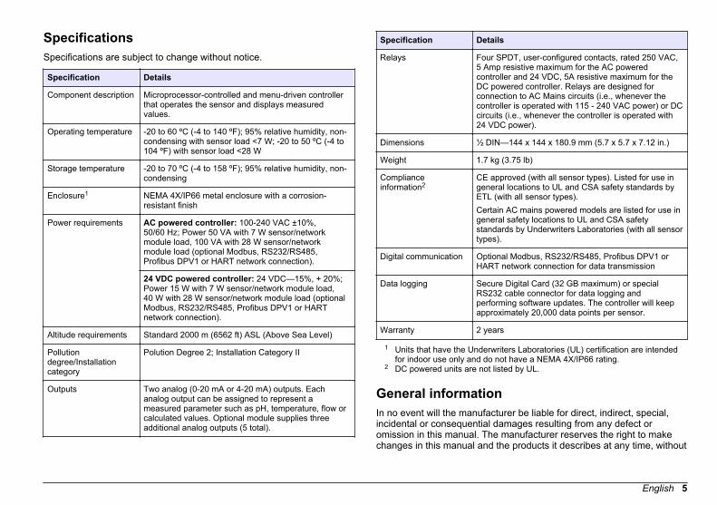
SpecificationsSpecifications are subject to change without notice.
Specification Details
Component description Microprocessor-controlled and menu-driven controllerthat operates the sensor and displays measuredvalues.
Operating temperature -20 to 60 ºC (-4 to 140 ºF); 95% relative humidity, non-condensing with sensor load <7 W; -20 to 50 ºC (-4 to104 ºF) with sensor load <28 W
Storage temperature -20 to 70 ºC (-4 to 158 ºF); 95% relative humidity, non-condensing
Enclosure1 NEMA 4X/IP66 metal enclosure with a corrosion-resistant finish
Power requirements AC powered controller: 100-240 VAC ±10%,50/60 Hz; Power 50 VA with 7 W sensor/networkmodule load, 100 VA with 28 W sensor/networkmodule load (optional Modbus, RS232/RS485,Profibus DPV1 or HART network connection).
24 VDC powered controller: 24 VDC—15%, + 20%;Power 15 W with 7 W sensor/network module load,40 W with 28 W sensor/network module load (optionalModbus, RS232/RS485, Profibus DPV1 or HARTnetwork connection).
Altitude requirements Standard 2000 m (6562 ft) ASL (Above Sea Level)
Pollutiondegree/Installationcategory
Polution Degree 2; Installation Category II
Outputs Two analog (0-20 mA or 4-20 mA) outputs. Eachanalog output can be assigned to represent ameasured parameter such as pH, temperature, flow orcalculated values. Optional module supplies threeadditional analog outputs (5 total).
Specification Details
Relays Four SPDT, user-configured contacts, rated 250 VAC,5 Amp resistive maximum for the AC poweredcontroller and 24 VDC, 5A resistive maximum for theDC powered controller. Relays are designed forconnection to AC Mains circuits (i.e., whenever thecontroller is operated with 115 - 240 VAC power) or DCcircuits (i.e., whenever the controller is operated with24 VDC power).
Dimensions ½ DIN—144 x 144 x 180.9 mm (5.7 x 5.7 x 7.12 in.)
Weight 1.7 kg (3.75 lb)
Complianceinformation2
CE approved (with all sensor types). Listed for use ingeneral locations to UL and CSA safety standards byETL (with all sensor types).Certain AC mains powered models are listed for use ingeneral safety locations to UL and CSA safetystandards by Underwriters Laboratories (with all sensortypes).
Digital communication Optional Modbus, RS232/RS485, Profibus DPV1 orHART network connection for data transmission
Data logging Secure Digital Card (32 GB maximum) or specialRS232 cable connector for data logging andperforming software updates. The controller will keepapproximately 20,000 data points per sensor.
Warranty 2 years
1 Units that have the Underwriters Laboratories (UL) certification are intendedfor indoor use only and do not have a NEMA 4X/IP66 rating.
2 DC powered units are not listed by UL.
General informationIn no event will the manufacturer be liable for direct, indirect, special,incidental or consequential damages resulting from any defect oromission in this manual. The manufacturer reserves the right to makechanges in this manual and the products it describes at any time, without
English 5

notice or obligation. Revised editions are found on the manufacturer’swebsite.
Safety informationN O T I C E
The manufacturer is not responsible for any damages due to misapplication ormisuse of this product including, without limitation, direct, incidental andconsequential damages, and disclaims such damages to the full extent permittedunder applicable law. The user is solely responsible to identify critical applicationrisks and install appropriate mechanisms to protect processes during a possibleequipment malfunction.
Please read this entire manual before unpacking, setting up or operatingthis equipment. Pay attention to all danger and caution statements.Failure to do so could result in serious injury to the operator or damageto the equipment.Make sure that the protection provided by this equipment is not impaired.Do not use or install this equipment in any manner other than thatspecified in this manual.
Use of hazard information
D A N G E R Indicates a potentially or imminently hazardous situation which, if not avoided, willresult in death or serious injury.
W A R N I N G Indicates a potentially or imminently hazardous situation which, if not avoided,could result in death or serious injury.
C A U T I O N Indicates a potentially hazardous situation that may result in minor or moderateinjury.
N O T I C E Indicates a situation which, if not avoided, may cause damage to the instrument.Information that requires special emphasis.
Precautionary labelsRead all labels and tags attached to the instrument. Personal injury ordamage to the instrument could occur if not observed. A symbol on theinstrument is referenced in the manual with a precautionary statement.
This symbol, if noted on the instrument, references the instructionmanual for operation and/or safety information.
This symbol indicates that a risk of electrical shock and/orelectrocution exists.
This symbol indicates the presence of devices sensitive to Electro-static Discharge (ESD) and indicates that care must be taken toprevent damage with the equipment.
Electrical equipment marked with this symbol may not be disposed ofin European public disposal systems after 12 August of 2005. Inconformity with European local and national regulations (EU Directive2002/96/EC), European electrical equipment users must now returnold or end-of-life equipment to the Producer for disposal at no chargeto the user.
CertificationCanadian Radio Interference-Causing Equipment Regulation,IECS-003, Class A:Supporting test records reside with the manufacturer.This Class A digital apparatus meets all requirements of the CanadianInterference-Causing Equipment Regulations.Cet appareil numèrique de la classe A respecte toutes les exigences duRëglement sur le matériel brouilleur du Canada.FCC Part 15, Class "A" LimitsSupporting test records reside with the manufacturer. The devicecomplies with Part 15 of the FCC Rules. Operation is subject to thefollowing conditions:
6 English
1. The equipment may not cause harmful interference.2. The equipment must accept any interference received, including
interference that may cause undesired operation.
Changes or modifications to this equipment not expressly approved bythe party responsible for compliance could void the user's authority tooperate the equipment. This equipment has been tested and found tocomply with the limits for a Class A digital device, pursuant to Part 15 ofthe FCC rules. These limits are designed to provide reasonableprotection against harmful interference when the equipment is operatedin a commercial environment. This equipment generates, uses and canradiate radio frequency energy and, if not installed and used inaccordance with the instruction manual, may cause harmful interferenceto radio communications. Operation of this equipment in a residentialarea is likely to cause harmful interference, in which case the user will berequired to correct the interference at their expense. The followingtechniques can be used to reduce interference problems:
1. Disconnect the equipment from its power source to verify that it is oris not the source of the interference.
2. If the equipment is connected to the same outlet as the deviceexperiencing interference, connect the equipment to a differentoutlet.
3. Move the equipment away from the device receiving the interference.4. Reposition the receiving antenna for the device receiving the
interference.5. Try combinations of the above.
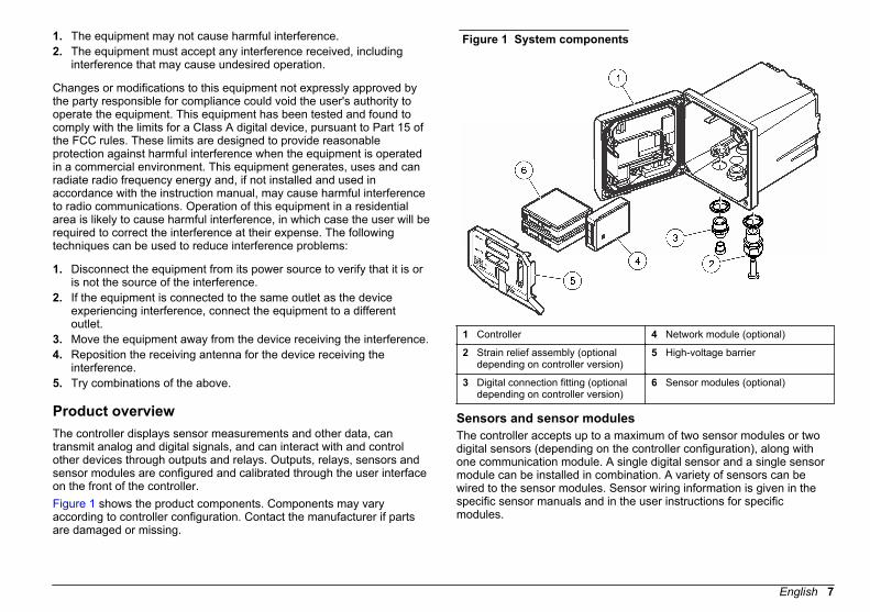
Product overviewThe controller displays sensor measurements and other data, cantransmit analog and digital signals, and can interact with and controlother devices through outputs and relays. Outputs, relays, sensors andsensor modules are configured and calibrated through the user interfaceon the front of the controller.Figure 1 shows the product components. Components may varyaccording to controller configuration. Contact the manufacturer if partsare damaged or missing.
Figure 1 System components
1 Controller 4 Network module (optional)
2 Strain relief assembly (optionaldepending on controller version)
5 High-voltage barrier
3 Digital connection fitting (optionaldepending on controller version)
6 Sensor modules (optional)
Sensors and sensor modulesThe controller accepts up to a maximum of two sensor modules or twodigital sensors (depending on the controller configuration), along withone communication module. A single digital sensor and a single sensormodule can be installed in combination. A variety of sensors can bewired to the sensor modules. Sensor wiring information is given in thespecific sensor manuals and in the user instructions for specificmodules.
English 7
Relays outputs and signalsThe controller has four configurable relay switches and two analogoutputs. An optional analog output module can increase the number ofanalog outputs to five.
Device scansWith two exceptions, the controller automatically scans for connecteddevices without user input when it is powered on. The first exception iswhen the controller is powered on for the first time before initial use. Thesecond exception is after the controller configuration settings have beenset to their default values and the controller is powered on. In bothcases, the controller first displays the language, date and time editscreens. After the language, date and time entries are accepted, thecontroller performs a device scan. Refer to Connect a digital sc sensoron page 20 for instructions about how to scan for devices when thecontroller is already powered on.
Controller enclosureThe controller enclosure is NEMA 4X/IP66-rated and has a corrosion-resistant finish designed to withstand corrosive environmentalconstituents such as salt spray and hydrogen sulfide. Protection againstenvironmental damage is strongly recommended for outdoor use.Note: Units that have the Underwriters Laboratories (UL) certification are intendedfor indoor use only and do not have a NEMA 4X/IP66 rating.
Controller mounting optionsThe controller can be mounted to a panel, to a wall or to a vertical orhorizontal pipe. A neoprene sealing gasket is included and can be usedto reduce vibration. The gasket can be used as a template for panelmounting before the inner gasket component is separated.
Installation
Mounting components and dimensions
C A U T I O N Personal injury hazard. Only qualified personnel should conduct the tasksdescribed in this section of the manual.
The controller can be installed on a surface, panel or pipe (horizontal orvertical). For mounting options and instructions, refer to Figure 2, Figure 3 on page 9, Figure 4 on page 10, Figure 5 on page 10and Figure 6 on page 11.For horizontal pipe mounts, the mounting feet (Figure 2) must beattached to the mounting bracket in a vertical position.For both horizontal and vertical pipe mounts, attach the mountingbracket to the controller as shown in Figure 5 on page 10.
8 English

Figure 2 Mounting components
1 Mounting foot (2x) 6 Flat washer, ¼-inch ID (4x)
2 Sealing gasket for panel mount,Neoprene
7 Lock washer, ¼-inch ID (4x)
3 Bracket for wall and pipe mounting 8 M5 x 0.8 Keps hexnut (4x)
4 Vibration isolation gasket for pipemount
9 Pan head screws, M5 x 0.8 x100mm (4x) (Used for variablediameter pipe mount installations)
5 Vibration isolation washer for pipemount (4x)
10 Pan head screws, M5 x 0.8 x15 mm (4x)
Note: A bracket for panel mounting is available as an optional accessory.
Controller mountingFigure 3 Surface mounting dimensions
English 9
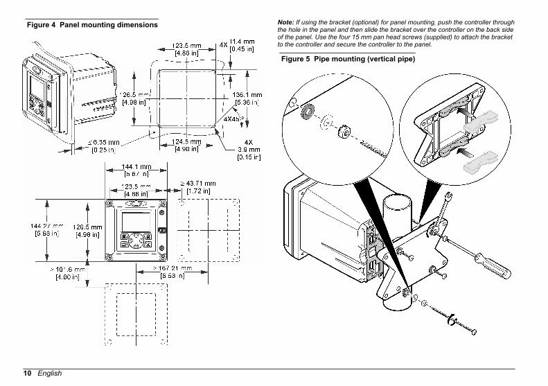
Figure 4 Panel mounting dimensions Note: If using the bracket (optional) for panel mounting, push the controller throughthe hole in the panel and then slide the bracket over the controller on the back sideof the panel. Use the four 15 mm pan head screws (supplied) to attach the bracketto the controller and secure the controller to the panel.
Figure 5 Pipe mounting (vertical pipe)
10 English
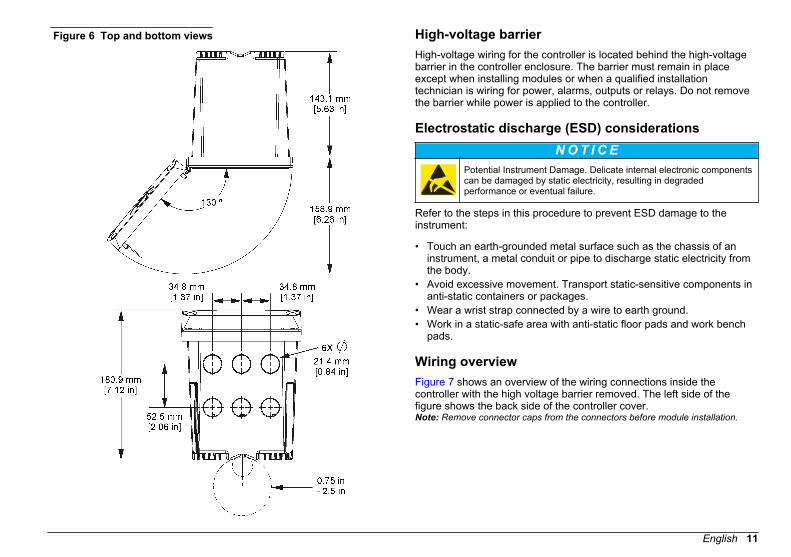
Figure 6 Top and bottom views High-voltage barrierHigh-voltage wiring for the controller is located behind the high-voltagebarrier in the controller enclosure. The barrier must remain in placeexcept when installing modules or when a qualified installationtechnician is wiring for power, alarms, outputs or relays. Do not removethe barrier while power is applied to the controller.
Electrostatic discharge (ESD) considerationsN O T I C E
Potential Instrument Damage. Delicate internal electronic componentscan be damaged by static electricity, resulting in degradedperformance or eventual failure.
Refer to the steps in this procedure to prevent ESD damage to theinstrument:
• Touch an earth-grounded metal surface such as the chassis of aninstrument, a metal conduit or pipe to discharge static electricity fromthe body.
• Avoid excessive movement. Transport static-sensitive components inanti-static containers or packages.
• Wear a wrist strap connected by a wire to earth ground.• Work in a static-safe area with anti-static floor pads and work bench
pads.
Wiring overviewFigure 7 shows an overview of the wiring connections inside thecontroller with the high voltage barrier removed. The left side of thefigure shows the back side of the controller cover.Note: Remove connector caps from the connectors before module installation.
English 11
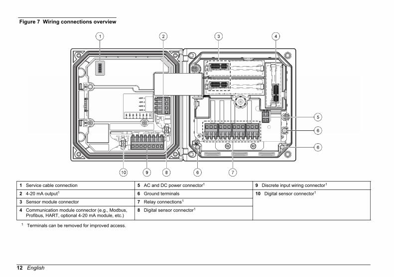
Figure 7 Wiring connections overview
1 Service cable connection 5 AC and DC power connector1 9 Discrete input wiring connector1
2 4-20 mA output1 6 Ground terminals 10 Digital sensor connector1
3 Sensor module connector 7 Relay connections1
4 Communication module connector (e.g., Modbus,Profibus, HART, optional 4-20 mA module, etc.)
8 Digital sensor connector1
1 Terminals can be removed for improved access.
12 English
Wiring for power
W A R N I N G Potential Electrocution Hazard. Always disconnect power to theinstrument when making electrical connections.
W A R N I N G Potential Electrocution Hazard. If this equipment is used outdoors or inpotentially wet locations, a Ground Fault Interrupt device must beused for connecting the equipment to its mains power source.
D A N G E R Electrocution Hazard. Do not connect AC power to a 24 VDC poweredmodel.
W A R N I N G Potential Electrocution Hazard. A protective earth (PE) groundconnection is required for both 100-240 VAC and 24 VDC wiringapplications. Failure to connect a good PE ground connection canresult in shock hazards and poor performance due to electromagneticinterferences. ALWAYS connect a good PE ground to the controllerterminal.
N O T I C E Install the device in a location and position that gives easy access to thedisconnect device and its operation.
The controller can be purchased as either a 100-240 VAC poweredmodel or a 24 VDC powered model. Follow the appropriate wiringinstructions for the purchased model.
The controller can be wired for line power by hard-wiring in conduit orwiring to a power cord. Regardless of the wire used, the connections aremade at the same terminals. A local disconnect designed to meet localelectrical code is required and must be identified for all types ofinstallation. In hard-wired applications, the power and safety groundservice drops for the instrument must be 18 to 12 AWG.Notes:
• The voltage barrier must be removed before making any electricalconnections. After making all connections, replace the voltage barrierbefore closing the controller cover.
• A sealing type strain relief and a power cord less than 3 meters(10 feet) in length with three 18-gauge conductors (including a safetyground wire) can be used to maintain the NEMA4X/IP66 environmental rating.
• Controllers can be ordered with AC power cords pre-installed.Additional power cords may also be ordered.
• The DC power source that supplies power to the 24 VDC poweredcontroller must maintain voltage regulation within the specified24 VDC-15% +20% voltage limits. The DC power source must alsoprovide adequate protection against surges and line transients.
Wiring procedureRefer to the illustrated steps that follow and Table 1 or Table 2 to wirethe controller for power. Insert each wire into the appropriate terminaluntil the insulation is seated against the connector with no bare wireexposed. Tug gently after insertion to make sure that there is a secureconnection. Seal any unused openings in the controller box with conduitopening sealing plugs.
English 13

14 English

Table 1 AC power wiring information (AC powered models only)
Terminal Description Color—NorthAmerica Color—EU
1 Hot (L1) Black Brown
2 Neutral (N) White Blue
— Protective Earth (PE)Ground lug
Green Green with yellowstripe
Table 2 DC power wiring information (DC powered models only)
Terminal Description Color—NorthAmerica Color—EU
1 +24 VDC Red Red
2 24 VDC return Black Black
— Protective Earth (PE)Ground lug
Green Green with yellowstripe
Alarms and relaysThe controller is equipped with four unpowered, single pole relays rated100-250 VAC, 50/60 Hz, 5 amp resistive maximum. Contacts are rated250 VAC, 5 amp resistive maximum for the AC powered controller and24 VDC, 5A resistive maximum for the DC powered controller. Therelays are not rated for inductive loads.
Wiring relays
W A R N I N G Potential Electrocution Hazard. Always disconnect power to theinstrument when making electrical connections.
W A R N I N G Potential fire hazard. The relay contacts are rated 5A and are notfused. External loads connected to the relays must have currentlimiting devices provided to limit current to < 5 A.
W A R N I N G Potential fire hazard. Do not daisy-chain the common relayconnections or jumper wire from the mains power connection insidethe instrument.
W A R N I N G Potential electrocution hazard. In order to maintain the NEMA/IPenvironmental ratings of the enclosure, use only conduit fittings andcable glands rated for at least NEMA 4X/IP66 to route cables in to theinstrument.
AC line (100—250 V) powered controllersThe wiring compartment is not designed for voltage connections inexcess of 250 VAC.24 VDC powered controllers
W A R N I N G Potential electrocution hazard. AC mains powered controllers(115 V–230 V) are designed for relay connections to AC mains circuits(i.e., voltages greater than 16 V-RMS, 22.6 V-PEAK or 35 VDC).
W A R N I N G Potential electrocution hazard. 24 V powered controllers are designedfor relay connections to low voltage circuits (i.e., voltages less than16 V-RMS, 22.6 V-PEAK or 35 VDC).
English 15

The 24 VDC controller relays are designed for the connection to lowvoltage circuits (i.e., voltages less than 30 V-RMS, 42.2 V-PEAK or60 VDC). The wiring compartment is not designed for voltageconnections above these levels.The relay connector accepts 18–12 AWG wire (as determined by loadapplication). Wire gauge less than 18 AWG is not recommended.
The Normally Open (NO) and Common (COM) relay contacts will beconnected when an alarm or other condition is active. The NormallyClosed (NC) and Common relay contacts will be connected when analarm or other condition is inactive (unless the Fail Safe is set to Yes) orwhen power is removed from the controller.Most relay connections use either the NO and COM terminals or the NCand COM terminals. The numbered installation steps show connection tothe NO and COM terminals.
16 English

English 17
Analog output connections
W A R N I N G Potential Electrocution Hazard. Always disconnect power to theinstrument when making electrical connections.
W A R N I N G Potential electrocution hazard. In order to maintain the NEMA/IPenvironmental ratings of the enclosure, use only conduit fittings andcable glands rated for at least NEMA 4X/IP66 to route cables in to theinstrument.
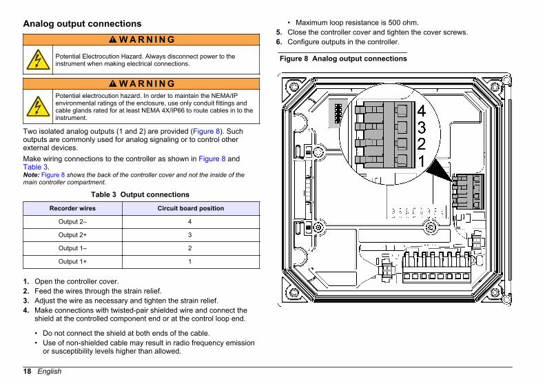
Two isolated analog outputs (1 and 2) are provided (Figure 8). Suchoutputs are commonly used for analog signaling or to control otherexternal devices.Make wiring connections to the controller as shown in Figure 8 and Table 3.Note: Figure 8 shows the back of the controller cover and not the inside of themain controller compartment.
Table 3 Output connections
Recorder wires Circuit board position
Output 2– 4
Output 2+ 3
Output 1– 2
Output 1+ 1
1. Open the controller cover.2. Feed the wires through the strain relief.3. Adjust the wire as necessary and tighten the strain relief.4. Make connections with twisted-pair shielded wire and connect the
shield at the controlled component end or at the control loop end.
• Do not connect the shield at both ends of the cable.• Use of non-shielded cable may result in radio frequency emission
or susceptibility levels higher than allowed.
• Maximum loop resistance is 500 ohm.5. Close the controller cover and tighten the cover screws.6. Configure outputs in the controller.
Figure 8 Analog output connections
18 English

Discrete input wiring connections
W A R N I N G Potential Electrocution Hazard. Always disconnect power to theinstrument when making electrical connections.
W A R N I N G Potential electrocution hazard. In order to maintain the NEMA/IPenvironmental ratings of the enclosure, use only conduit fittings andcable glands rated for at least NEMA 4X/IP66 to route cables in to theinstrument.
Three discrete inputs are provided for switch closure inputs or logic levelvoltage inputs. Make wiring connections and configure jumper settings tothe controller as shown in Figure 9, Table 4 and Figure 10.Note: Figure 9 shows the back of the controller cover and not the inside of themain controller compartment.
Figure 9 Discrete input wiring connections
Table 4 Input connections
Discrete inputs Connector position -Switch input
Connector position -Voltage input
Input 1+ 3 2
Input 1- 2 3
Input 2+ 6 5
English 19

Table 4 Input connections (continued)
Discrete inputs Connector position -Switch input
Connector position -Voltage input
Input 2- 5 6
Input 3+ 8 7
Input 3- 7 8
Figure 10 Jumper settings
1 Input 1 configuration jumpers 4 Jumpers positioned to the left forswitch inputs
2 Input 2 configuration jumpers 5 Jumpers positioned to the right forvoltage inputs3 Input 3 configuration jumpers
1. Open the controller cover.2. Feed the wires through the cable gland.3. Adjust the wire as necessary and tighten the cable gland.4. The jumpers are positioned immediately behind the connector.
Remove the connector for improved access to the jumpers andconfigure the jumper settings according to the type of input as shownin Figure 10.
5. Close the controller cover and tighten the cover screws.6. Configure inputs in the controller.
Note: In switch input mode the controller supplies 12 volts to the switch and is notisolated from the controller. In voltage input mode the inputs are isolated from thecontroller (user input voltage from 0 to 30 volts).
Connect a digital sc sensorNote: To connect an analog sensor, refer to the instructions supplied in the moduleor sensor manual.
A digital sc sensor can be connected to the controller using the keyedquick-connect fitting (Figure 11). A digital sensor can be connected withthe controller powered on or off.When a sensor is connected with the controller powered on, thecontroller does not automatically perform a device scan. To make thecontroller perform a device scan, navigate to the Test/Maintenancemenu and select Scan Devices. If a new device is found, the controllerperforms the installation process without further user action.When a sensor is connected with the controller powered off, thecontroller will perform a device scan when it is powered on again. If anew device is found, the controller performs the installation processwithout further user action.Retain the connector cap to seal the connector opening in case thesensor must be removed.
Figure 11 Digital sensor quick connect
1.
Connect the optional digital communication outputThe manufacturer supports Modbus RS485, Modbus RS232, ProfibusDPV1 and HART communication protocols. The optional digital output
20 English

module is installed in the location indicated by item 4 in Figure 7on page 12. Refer to the instructions supplied with the network modulefor more details.For information about Modbus registers, go to http://www.hach-lange.com or http://www.hach.com and search Modbus registers or go toany sc200 product page.
Install a Secure Digital (SD) memory cardFor instructions on how to install an SD card in the controller, refer to Figure 12. Information on how to use the SD memory card can be foundin Using the secure digital memory (SD) card on page 38.To remove an SD card, push down on the edge of the card and release,then pull the card up and out of the slot. After the card is removed, closethe slot cover and tighten the cover screws.
Figure 12 SD card installation
User interface and navigation
User interfaceThe keypad has four menu keys and four directional keys as shown in Figure 13.
Figure 13 Keypad and front panel overview
1 Instrument display 5 BACK key. Moves back one level inthe menu structure.
2 Cover for secure digital memorycard slot
6 MENU key. Moves to the SettingsMenu from other screens andsubmenus.
3 HOME key. Moves to the MainMeasurement screen from otherscreens and submenus.
7 Directional keys. Used to navigatethrough the menus, changesettings, and increment ordecrement digits.4 ENTER key. Accepts input values,
updates, or displayed menuoptions.
English 21
Inputs and outputs are set up and configured through the front panelusing the keypad and display screen. This user interface is used to setup and configure inputs and outputs, create log information andcalculated values, and calibrate sensors. The SD interface can be usedto save logs and update software.
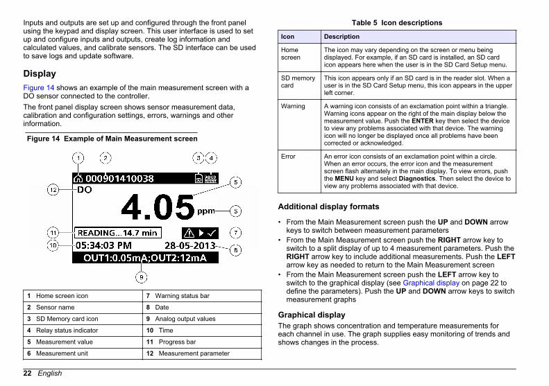
DisplayFigure 14 shows an example of the main measurement screen with aDO sensor connected to the controller.The front panel display screen shows sensor measurement data,calibration and configuration settings, errors, warnings and otherinformation.
Figure 14 Example of Main Measurement screen
1 Home screen icon 7 Warning status bar
2 Sensor name 8 Date
3 SD Memory card icon 9 Analog output values
4 Relay status indicator 10 Time
5 Measurement value 11 Progress bar
6 Measurement unit 12 Measurement parameter
Table 5 Icon descriptions
Icon Description
Homescreen
The icon may vary depending on the screen or menu beingdisplayed. For example, if an SD card is installed, an SD cardicon appears here when the user is in the SD Card Setup menu.
SD memorycard
This icon appears only if an SD card is in the reader slot. When auser is in the SD Card Setup menu, this icon appears in the upperleft corner.
Warning A warning icon consists of an exclamation point within a triangle.Warning icons appear on the right of the main display below themeasurement value. Push the ENTER key then select the deviceto view any problems associated with that device. The warningicon will no longer be displayed once all problems have beencorrected or acknowledged.
Error An error icon consists of an exclamation point within a circle.When an error occurs, the error icon and the measurementscreen flash alternately in the main display. To view errors, pushthe MENU key and select Diagnostics. Then select the device toview any problems associated with that device.
Additional display formats
• From the Main Measurement screen push the UP and DOWN arrowkeys to switch between measurement parameters
• From the Main Measurement screen push the RIGHT arrow key toswitch to a split display of up to 4 measurement parameters. Push theRIGHT arrow key to include additional measurements. Push the LEFTarrow key as needed to return to the Main Measurement screen
• From the Main Measurement screen push the LEFT arrow key toswitch to the graphical display (see Graphical display on page 22 todefine the parameters). Push the UP and DOWN arrow keys to switchmeasurement graphs
Graphical displayThe graph shows concentration and temperature measurements foreach channel in use. The graph supplies easy monitoring of trends andshows changes in the process.
22 English
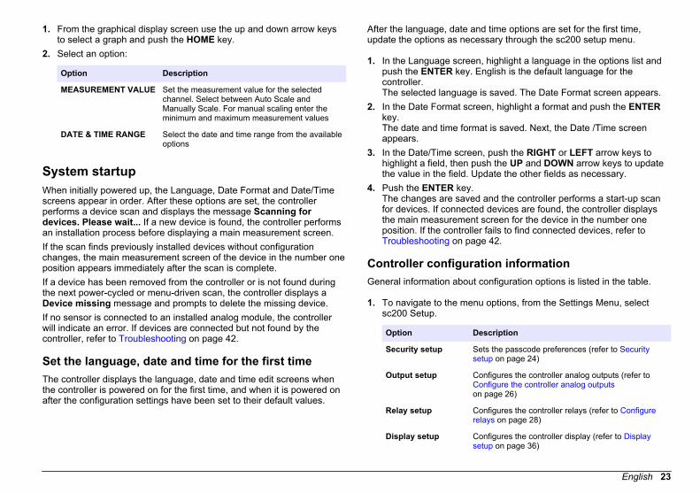
1. From the graphical display screen use the up and down arrow keysto select a graph and push the HOME key.
2. Select an option:
Option Description
MEASUREMENT VALUE Set the measurement value for the selectedchannel. Select between Auto Scale andManually Scale. For manual scaling enter theminimum and maximum measurement values
DATE & TIME RANGE Select the date and time range from the availableoptions
System startupWhen initially powered up, the Language, Date Format and Date/Timescreens appear in order. After these options are set, the controllerperforms a device scan and displays the message Scanning fordevices. Please wait... If a new device is found, the controller performsan installation process before displaying a main measurement screen.If the scan finds previously installed devices without configurationchanges, the main measurement screen of the device in the number oneposition appears immediately after the scan is complete.If a device has been removed from the controller or is not found duringthe next power-cycled or menu-driven scan, the controller displays aDevice missing message and prompts to delete the missing device.If no sensor is connected to an installed analog module, the controllerwill indicate an error. If devices are connected but not found by thecontroller, refer to Troubleshooting on page 42.
Set the language, date and time for the first timeThe controller displays the language, date and time edit screens whenthe controller is powered on for the first time, and when it is powered onafter the configuration settings have been set to their default values.
After the language, date and time options are set for the first time,update the options as necessary through the sc200 setup menu.
1. In the Language screen, highlight a language in the options list andpush the ENTER key. English is the default language for thecontroller.The selected language is saved. The Date Format screen appears.
2. In the Date Format screen, highlight a format and push the ENTERkey.The date and time format is saved. Next, the Date /Time screenappears.
3. In the Date/Time screen, push the RIGHT or LEFT arrow keys tohighlight a field, then push the UP and DOWN arrow keys to updatethe value in the field. Update the other fields as necessary.
4. Push the ENTER key.The changes are saved and the controller performs a start-up scanfor devices. If connected devices are found, the controller displaysthe main measurement screen for the device in the number oneposition. If the controller fails to find connected devices, refer to Troubleshooting on page 42.
Controller configuration informationGeneral information about configuration options is listed in the table.
1. To navigate to the menu options, from the Settings Menu, selectsc200 Setup.
Option Description
Security setup Sets the passcode preferences (refer to Securitysetup on page 24)
Output setup Configures the controller analog outputs (refer to Configure the controller analog outputson page 26)
Relay setup Configures the controller relays (refer to Configurerelays on page 28)
Display setup Configures the controller display (refer to Displaysetup on page 36)
English 23

Option Description
Set Date/Time Sets the controller time and date (refer to Update thedate and time on page 36)
Datalog setup Configures data logging options. Available only ifCalculation has been setup. At least one sensor mustbe attached to enter a calculation (refer to Set thedatalog mode and interval on page 37)
Manage Data Select the device from the list of installedcomponents to view the data or event log
Error Hold Mode Hold Outputs—Holds outputs at last known valuewhen controller loses communication with thesensor.Transfer Outputs—Switches to transfer mode whencontroller loses communication with the sensor.Outputs transfer to a pre-defined value.
Calculation Configures the controller math function (refer to Setup a calculation on page 37)
sc200 Information S/W VER:—Displays the current version of controllersoftwareBootloader VER:—Displays the current Bootloaderversion. The Bootloader is a file that loads the mainoperating system for the controllerS/N:—Displays the controller serial numberVersion:—Displays the current version of controllerhardware
Discrete Input Setup Configures three discrete input channels (refer to Setup the discrete inputs on page 37)
Language Assigns the language used in the controller (refer to Update the display language on page 38)
2. Select an option and push ENTER to activate the menu item.
Advanced operation
Security setupEnable or disable the passcodeBy default the passcode option is disabled and all configuration settingsand calibrations can be changed. When the passcode function isenabled, access to Sensor calibration and Test/Maint menus requires apasscode.To enable the passcode:
1. From the Settings Menu, select sc200 Setup and push the ENTERkey.
2. Select Security Setup and push the ENTER key.3. Select Set Passcode and push the ENTER key.4. Select Disabled or Enabled and push the ENTER key.
The passcode is enabled.5. Push the BACK key to return to the sc200 Setup Menu, or push the
MENU key to return to the Settings Menu.
Edit the passcodeThe passcode is factory set to SC200. The Edit Passcode menu optionappears in the Security Setup menu only after the passcode feature isenabled and a valid passcode has been entered.A passcode consists of up to six upper or lower-case alpha, numeric andspecial characters. Passcodes are case-sensitive.To edit the passcode:
1. Make sure the passcode is enabled. Refer to Enable or disable thepasscode on page 24 for information on how to enable the passcode.
2. From the Settings menu, select Security Setup and push ENTER.3. Use the arrow keys to enter the current valid passcode and push
ENTER.The Edit Passcode option appears in the Security Setup menu.
4. Select Edit Pass Code and push ENTER.The Edit Pass Code screen appears.
5. Use the arrow keys to edit the passcode and push ENTER.
24 English
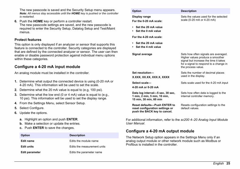
The new passcode is saved and the Security Setup menu appears.Note: All menus stay accessible until the HOME key is pushed or the controlleris restarted.
6. Push the HOME key or perform a controller restart.The new passcode settings are saved, and the new passcode isrequired to enter the Security Setup, Datalog Setup and Test/Maintmenus.
Protect featuresThis option is only displayed if an analyzer or sensor that supports thisfeature is connected to the controller. Security categories are displayedthat are defined by the connected analyzer or sensor. The user can thenenable or disable password protection against individual menu optionswithin these categories.
Configure a 4-20 mA input moduleAn analog module must be installed in the controller.
1. Determine what output the connected device is using (0-20 mA or4-20 mA). This information will be used to set the scale.
2. Determine what the 20 mA value is equal to (e.g, 100 psi).3. Determine what the low end (0 or 4 mA) value is equal to (e.g.,
10 psi). This information will be used to set the display range.4. From the Settings Menu, select Sensor Setup.5. Select Configure.6. Update the options.
a. Highlight an option and push ENTER.b. Make a selection or update the entries.c. Push ENTER to save the changes.
Option Description
Edit name Edits the module name
Edit units Edits the measurement units
Edit parameter Edits the parameter name
Option Description
Display rangeFor the 0-20 mA scale:
• Set the 20 mA value• Set the 0 mA value
For the 4-20 mA scale:
• Set the 20 mA value• Set the 4 mA value
Sets the values used for the selectedscale (0-20 mA or 4-20 mA)
Signal average Sets how often signals are averaged.Higher values produce a smoothersignal but increase the time it takesfor a signal to respond to a change inthe process value.
Set resolution—X.XXX, XX.XX, XXX.X, XXXX
Sets the number of decimal placesused in the display.
Select scale—4-20 mA or 0-20 mA
Sets scale used for the 4-20 mA input
Data log interval—5 sec, 30 sec,1 min, 2 min, 5 min, 10 min,15 min, 30 min, 60 min
Sets how often data is logged to theinternal controller memory.
Reset defaults—Push ENTER toreset configuration settings orpush the BACK key to cancel.
Resets configuration settings to thedefault values.
For additional information, refer to the sc200 4–20 Analog Input ModuleUser Manual.
Configure a 4-20 mA output moduleThe Network Setup option appears in the Settings Menu only if ananalog output module or other network module such as Modbus orProfibus is installed in the controller.
English 25
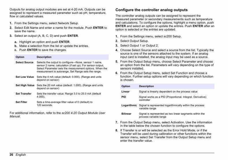
Outputs for analog output modules are set at 4-20 mA. Outputs can beassigned to represent a measured parameter such as pH, temperature,flow or calculated values.
1. From the Settings menu, select Network Setup.2. Select Edit Name and enter a name for the module. Push ENTER to
save the name.3. Select an output (A, B, C, D) and push ENTER.
a. Highlight an option and push ENTER.b. Make a selection from the list or update the entries.c. Push ENTER to save the changes.
Option Description
Select Source Selects the output to configure—None, sensor 1 name,sensor 2 name, calculation (if set up). For sensor output,Select Parameter sets the measurement options. When themeasurement is autorange, Set Range sets the range.
Set Low Value Sets the 4 mA value (default: 0.000). (Range and unitsdepend on sensor)
Set High Value Sets the 20 mA value (default: 1.000). (Range and unitsdepend on sensor)
Set Transfer Sets the transfer value. Range 3.0 to 25.0 mA (default4.000).
Set Filter Sets a time-average filter value of 0 (default) to120 seconds.
For additional information, refer to the sc200 4-20 Output Module UserManual.
Configure the controller analog outputsThe controller analog outputs can be assigned to represent themeasured parameter or secondary measurements such as temperatureand calculations. To configure the options, highlight a menu option, pushENTER and select an option or update the entries. Push ENTER after anoption is selected or the entries are updated.
1. From the Settings menu, select sc200 Setup.2. Select Output Setup.3. Select Output 1 or Output 2.4. Choose Select Source and select a source from the list. Typically the
source is one of the sensors attached to the system. If an analoginput card is installed, the analog input may be used as a source.
5. From the Output Setup menu, choose Select Parameter and choosean option from the list. Parameters will vary depending on the type ofsensors installed.
6. From the Output Setup menu, select Set Function and choose afunction. Further setup options will vary depending on which functionis chosen.
Option Description
Linear Signal is linearly dependent on the process value
PID Signal works as a PID (Proportional, Integral, Derivative)controller
Logarithmic Signal is represented logarithmically within the processvariable range
Bilinear Signal is represented as two linear segments within theprocess variable range
7. From the Output Setup menu, select Activation. Use the informationin the table below the chosen function to configure the options.
8. If Transfer is or will be selected as the Error Hold Mode, or if theTransfer will be used during calibration or other functions within thesensor menu, select Set Transfer from the Output Setup menu andenter the transfer value.
26 English

9. From the Output Setup menu, select Set Filter and enter the filtervalue.
10. From the Output Setup menu, select Scale and choose the scale(0-20 mA or 4-20 mA).
• Linear
Option Description
Set low value Sets the low endpoint of the process variable range
Set high value Sets the high endpoint of the process variable range
• PID
Option Description
Set mode (Autoor Manual)
Auto—the signal is automatically controlled by thealgorithm within the analyzer using proportional, integral,and derivative inputs.Manual—the signal is controlled by the user throughmanual adjustment of the % change value. This option isshown as Manual Output after the manual set mode isselected.
Phase (Director Reverse)
The direction in which the signal responds to processchange.Direct—signal increases as the process increases.Reverse—signal increases as process decreases.
Set setpoint Creates a desired control point of process
Prop band A function of the difference between the measured signaland the desired setpoint.
Integral The period of time from the injection point of a reagent tocontact with the measuring device.
Derivative Used to compensate for the 2nd order effects of theprocess. The majority of applications can be controlledwithout the use of the derivative setting.
Transit time Stops all PID control for a selected period of time as thesample travels from the control pump to the measurementsensor.
• Logarithmic
Option Description
Set 50% value Sets the value corresponding to 50% of the processvariable range.
Set high value Sets the upper value of the process variable range.
• Bilinear
Option Description
Set low value Sets the low endpoint value of the process variablerange.
Set high value Sets the high endpoint value of the process variablerange.
Set knee point value Sets the value at which the process variable rangedivides into another linear segment.
Set knee pointcurrent
Sets the value of the current at the knee point value.
English 27

Logarithmic output modeFigure 15 shows in graph form the operation of the logarithmic outputmode.
Figure 15 Logarithmic output
1 Output current axis 5 Minimum output current (0-4 mA)
2 Source value axis 6 50% output current
3 High value 7 Maximum output current (20 mA)
4 50% value
Bilinear output modeFigure 16 shows in graph form the operation of the bilinear output mode.
Figure 16 Bilinear output
1 Output current axis 5 Low value
2 Source value axis 6 Minimum output current (0-4 mA)
3 High value 7 Knee point current
4 Knee point value 8 Maximum output current (20 mA)
Configure relaysThe Normally Open (NO) and Common (COM) relay contacts will beconnected when an alarm or other condition is active. The NormallyClosed (NC) and Common relay contacts will be connected when analarm or other condition is inactive (unless the Fail Safe is set to Yes), orwhen power is removed from the controller. To select a menu option,highlight the option and push ENTER.
1. From the sc200 Setup menu, select Relay Setup.2. Select a relay from the list.
28 English

3. From the Relay Setup menu, choose Select Source and pushENTER. Normally, a source is one of the sensors attached to thesystem, but the controller can also function as a source. If an analoginput module is installed, the source may be the analog input.
4. From the Relay Setup menu, select Set Parameter and choose fromthe list of parameters. The list of parameter options will vary with thetype of attached sensor.
5. From the Relay Setup menu, select Set Function and choose fromthe list. Further setup will depend on the function chosen.
Option Description
Scheduler Function(available if thecontroller is selected asthe relay source)
Relay switches at certain times independentlyof any process value
Alarm Function Relay activates when upper or lower alarmvalue is exceeded
Feeder Control Function Relay indicates if a process value exceeds orfalls below a setpoint
Event Control Function Relay toggles if a process value reaches anupper or lower limit
Pulse Width Modulation(PWM) Control Function
Relay uses a Pulse Width Modulation controldepending on a process value
Frequency control Relay switches with a frequency depending ona process value
Warning Relay indicates warning and error conditions inprobes
6. From the Relay Setup menu, select Set Transfer and choose Activeor Inactive.
7. From the Relay Setup menu, select Fail Safe and choose Yes or No.8. From the Relay Setup menu, select Activation.
The activation options for the selected function appear. Use theinformation in the table below each function to update the options.
9. Test the relay function to make sure it is properly energizing theconnected device. To do relay testing, go to the Setting menu, thenselect Test/Maint>Test Relay.
• Scheduler Function (refer to Figure 17)
Option Description
Hold outputs Holds outputs in the present ON or OFF state
Run days Sets the weekday(s) that the relay operates. Options:Sunday, Monday, Tuesday., Wednesday, Thursday, Friday,Saturday
Start time Sets the start time.
Interval Sets the time between activation cycles (Default value:5 min).
Duration Sets the period of time the relay is energized (Default value:30 sec).
Off delay Sets the time for additional hold/output time after the relayhas been turned off.
Figure 17 Scheduler function
1 Duration 3 Interval
2 OFF delay 4 Time (x-axis)
English 29
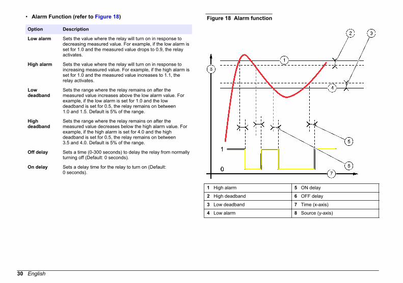
• Alarm Function (refer to Figure 18)
Option Description
Low alarm Sets the value where the relay will turn on in response todecreasing measured value. For example, if the low alarm isset for 1.0 and the measured value drops to 0.9, the relayactivates.
High alarm Sets the value where the relay will turn on in response toincreasing measured value. For example, if the high alarm isset for 1.0 and the measured value increases to 1.1, therelay activates.
Lowdeadband
Sets the range where the relay remains on after themeasured value increases above the low alarm value. Forexample, if the low alarm is set for 1.0 and the lowdeadband is set for 0.5, the relay remains on between1.0 and 1.5. Default is 5% of the range.
Highdeadband
Sets the range where the relay remains on after themeasured value decreases below the high alarm value. Forexample, if the high alarm is set for 4.0 and the highdeadband is set for 0.5, the relay remains on between3.5 and 4.0. Default is 5% of the range.
Off delay Sets a time (0-300 seconds) to delay the relay from normallyturning off (Default: 0 seconds).
On delay Sets a delay time for the relay to turn on (Default:0 seconds).
Figure 18 Alarm function
1 High alarm 5 ON delay
2 High deadband 6 OFF delay
3 Low deadband 7 Time (x-axis)
4 Low alarm 8 Source (y-axis)
30 English

• Feeder Control Function (refer to Figure 19 and Figure 20)
Option Description
Phase Defines the relay status if the process value exceeds thesetpoint.High (default)—turns the relay on when the process valueexceeds the setpoint.Low—turns the relay on when the process value fallsbelow the setpoint.
Set setpoint Sets the process value at which the relay toggles. Thedefault value is different for each sensor.
Deadband Sets the area for an amount of change necessary after therelay setpoint is reached in order to satisfy a condition.
Overfeed timer Sets a time period for de-activating an active relay if theprocess setpoint cannot be reached. Once an overfeedalarm is present, it must be manually reset.
Off delay Sets a delay time for the relay to turn off (default:0 seconds).
On delay Sets a delay time for the relay to turn on (default:0 seconds).
Figure 19 Feeder control function
1 Deadband (Phase = Low) 6 Time (x-axis)
2 Deadband (Phase = High) 7 ON delay (phase set high)
3 Setpoint 8 OFF delay (phase set low)
4 OFF delay (phase set high) 9 Source (y-axis)
5 ON delay (phase set low)
English 31

Figure 20 Feeder control function (Phase low, Overfeed timer)
1 Deadband 5 ON delay
2 Setpoint 6 OFF delay
3 Overfeed timer 7 Source (y-axis)
4 Time (x-axis)
• Event Control Function (refer to Figure 21, Figure 22 and Figure 23)
Option Description
Set setpoint Sets the value where the relay will turn on.
Deadband Sets a hysteresis so the relay will not swing unregulatedwhen the process value converges to the setpoint.
Option Description
OnMax timer Sets the maximum time the relay can stay on independentfrom the measured value (default: + 0 min).
OffMax timer Sets the maximum time the relay can stay off independentfrom the measured value (default: + 0 min).
OnMin timer Sets the minimum time the relay can stay on independentfrom the measured value (default: + 0 min).
OffMin timer Sets the minimum time the relay can stay off independentfrom the measured value (default: + 0 min).
32 English

Figure 21 Event control function (no delay)
1 Source (y-axis) 5 Low alarm
2 High alarm 6 Time (x-axis)
3 Deadband 7 OnMax-time
4 Setpoint 8 OffMax-time
Figure 22 Event control function (OnMin timer, OffMin timer)
1 High alarm 5 Time (x-axis)
2 Deadband 6 OffMin timer
3 Setpoint 7 OnMin timer
4 Low alarm 8 Source (y-axis)
English 33
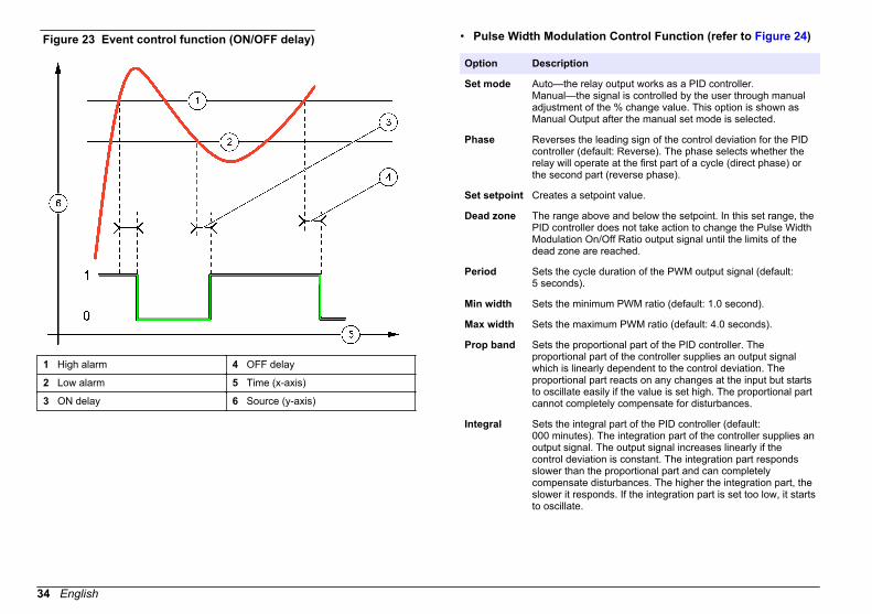
Figure 23 Event control function (ON/OFF delay)
1 High alarm 4 OFF delay
2 Low alarm 5 Time (x-axis)
3 ON delay 6 Source (y-axis)
• Pulse Width Modulation Control Function (refer to Figure 24)
Option Description
Set mode Auto—the relay output works as a PID controller.Manual—the signal is controlled by the user through manualadjustment of the % change value. This option is shown asManual Output after the manual set mode is selected.
Phase Reverses the leading sign of the control deviation for the PIDcontroller (default: Reverse). The phase selects whether therelay will operate at the first part of a cycle (direct phase) orthe second part (reverse phase).
Set setpoint Creates a setpoint value.
Dead zone The range above and below the setpoint. In this set range, thePID controller does not take action to change the Pulse WidthModulation On/Off Ratio output signal until the limits of thedead zone are reached.
Period Sets the cycle duration of the PWM output signal (default:5 seconds).
Min width Sets the minimum PWM ratio (default: 1.0 second).
Max width Sets the maximum PWM ratio (default: 4.0 seconds).
Prop band Sets the proportional part of the PID controller. Theproportional part of the controller supplies an output signalwhich is linearly dependent to the control deviation. Theproportional part reacts on any changes at the input but startsto oscillate easily if the value is set high. The proportional partcannot completely compensate for disturbances.
Integral Sets the integral part of the PID controller (default:000 minutes). The integration part of the controller supplies anoutput signal. The output signal increases linearly if thecontrol deviation is constant. The integration part respondsslower than the proportional part and can completelycompensate disturbances. The higher the integration part, theslower it responds. If the integration part is set too low, it startsto oscillate.
34 English
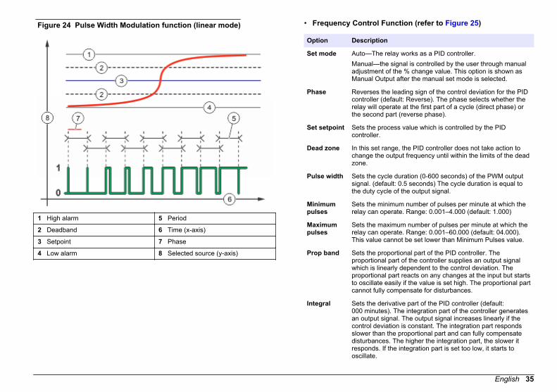
Figure 24 Pulse Width Modulation function (linear mode)
1 High alarm 5 Period
2 Deadband 6 Time (x-axis)
3 Setpoint 7 Phase
4 Low alarm 8 Selected source (y-axis)
• Frequency Control Function (refer to Figure 25)
Option Description
Set mode Auto—The relay works as a PID controller.Manual—the signal is controlled by the user through manualadjustment of the % change value. This option is shown asManual Output after the manual set mode is selected.
Phase Reverses the leading sign of the control deviation for the PIDcontroller (default: Reverse). The phase selects whether therelay will operate at the first part of a cycle (direct phase) orthe second part (reverse phase).
Set setpoint Sets the process value which is controlled by the PIDcontroller.
Dead zone In this set range, the PID controller does not take action tochange the output frequency until within the limits of the deadzone.
Pulse width Sets the cycle duration (0-600 seconds) of the PWM outputsignal. (default: 0.5 seconds) The cycle duration is equal tothe duty cycle of the output signal.
Minimumpulses
Sets the minimum number of pulses per minute at which therelay can operate. Range: 0.001–4.000 (default: 1.000)
Maximumpulses
Sets the maximum number of pulses per minute at which therelay can operate. Range: 0.001–60.000 (default: 04.000).This value cannot be set lower than Minimum Pulses value.
Prop band Sets the proportional part of the PID controller. Theproportional part of the controller supplies an output signalwhich is linearly dependent to the control deviation. Theproportional part reacts on any changes at the input but startsto oscillate easily if the value is set high. The proportional partcannot fully compensate for disturbances.
Integral Sets the derivative part of the PID controller (default:000 minutes). The integration part of the controller generatesan output signal. The output signal increases linearly if thecontrol deviation is constant. The integration part respondsslower than the proportional part and can fully compensatedisturbances. The higher the integration part, the slower itresponds. If the integration part is set too low, it starts tooscillate.
English 35

Figure 25 Frequency control function
1 High limit 5 Cycle duration
2 Deadband 6 Time (x-axis)
3 Setpoint 7 Selected source (y-axis)
4 Low limit
• Warning Function
Option Description
Warning Sets the level for warning activation. Refer to the sensor manualfor the numbers for individual warning messages.
Display setupConfigures the controller display.
1. From the Settings menu, select sc200 Setup and push ENTER.
2. Select Display Setup and push ENTER.
Option Description
AdjustOrder
View and modify the measurement display order.
• See Current Order—View the current display order• Add Measurements—Add selected measurements to the
display• Remove Measurements—Remove selected
measurements from the display• Reorder List—Select one or more measurements and
change their order in the display• See Default Order—View the default display order• Set to Default—Set the display order to the default
configuration
Note: Some of the above will not be available if no adjustmentis possible for that option (e.g. Reorder List and RemoveMeasurements will not be available if only one measurementis selected for display).
DisplayContrast
Adjust the contrast to a value between the minimum of +1 andthe maximum of +9
Edit Name Assigns a name to the controller
Update the date and time
1. From the Settings menu, select sc200 Setup and push ENTER.2. Select Set Date/Time and push ENTER.3. Select Date Format from the Set Date/Time screen and push
ENTER.4. Select a format and push ENTER.5. Select Date/Time from the Set Date/Time screen and push ENTER.6. Update the entries.
a. Use the right and left arrow keys to highlight a field.b. Use the up and down arrow keys to change the values in the field
and push ENTER.
36 English
c. At the end of the date field, push the right arrow to wrap down tothe time fields.
d. Use the up and down and arrow keys to update the time fields.7. Push ENTER to save the changes.
The controller returns to the Set Date/Time menu.
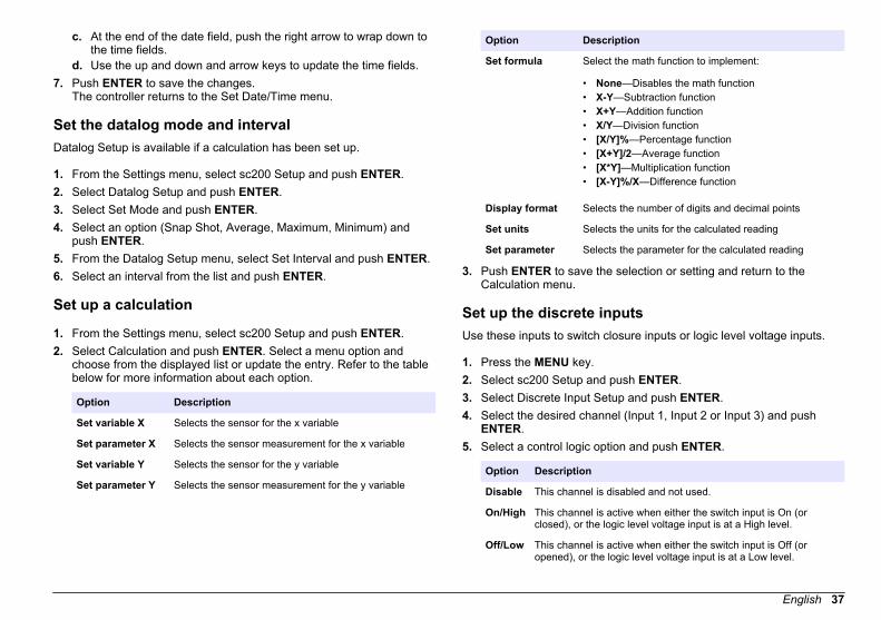
Set the datalog mode and intervalDatalog Setup is available if a calculation has been set up.
1. From the Settings menu, select sc200 Setup and push ENTER.2. Select Datalog Setup and push ENTER.3. Select Set Mode and push ENTER.4. Select an option (Snap Shot, Average, Maximum, Minimum) and
push ENTER.5. From the Datalog Setup menu, select Set Interval and push ENTER.6. Select an interval from the list and push ENTER.
Set up a calculation
1. From the Settings menu, select sc200 Setup and push ENTER.2. Select Calculation and push ENTER. Select a menu option and
choose from the displayed list or update the entry. Refer to the tablebelow for more information about each option.
Option Description
Set variable X Selects the sensor for the x variable
Set parameter X Selects the sensor measurement for the x variable
Set variable Y Selects the sensor for the y variable
Set parameter Y Selects the sensor measurement for the y variable
Option Description
Set formula Select the math function to implement:
• None—Disables the math function• X-Y—Subtraction function• X+Y—Addition function• X/Y—Division function• [X/Y]%—Percentage function• [X+Y]/2—Average function• [X*Y]—Multiplication function• [X-Y]%/X—Difference function
Display format Selects the number of digits and decimal points
Set units Selects the units for the calculated reading
Set parameter Selects the parameter for the calculated reading
3. Push ENTER to save the selection or setting and return to theCalculation menu.
Set up the discrete inputsUse these inputs to switch closure inputs or logic level voltage inputs.
1. Press the MENU key.2. Select sc200 Setup and push ENTER.3. Select Discrete Input Setup and push ENTER.4. Select the desired channel (Input 1, Input 2 or Input 3) and push
ENTER.5. Select a control logic option and push ENTER.
Option Description
Disable This channel is disabled and not used.
On/High This channel is active when either the switch input is On (orclosed), or the logic level voltage input is at a High level.
Off/Low This channel is active when either the switch input is Off (oropened), or the logic level voltage input is at a Low level.
English 37
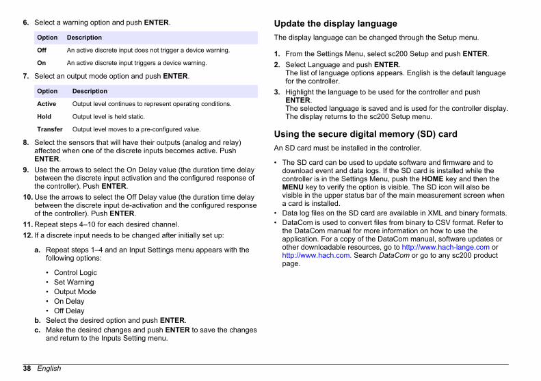
6. Select a warning option and push ENTER.
Option Description
Off An active discrete input does not trigger a device warning.
On An active discrete input triggers a device warning.
7. Select an output mode option and push ENTER.
Option Description
Active Output level continues to represent operating conditions.
Hold Output level is held static.
Transfer Output level moves to a pre-configured value.
8. Select the sensors that will have their outputs (analog and relay)affected when one of the discrete inputs becomes active. PushENTER.
9. Use the arrows to select the On Delay value (the duration time delaybetween the discrete input activation and the configured response ofthe controller). Push ENTER.
10. Use the arrows to select the Off Delay value (the duration time delaybetween the discrete input de-activation and the configured responseof the controller). Push ENTER.
11. Repeat steps 4–10 for each desired channel.12. If a discrete input needs to be changed after initially set up:
a. Repeat steps 1–4 and an Input Settings menu appears with thefollowing options:
• Control Logic• Set Warning• Output Mode• On Delay• Off Delay
b. Select the desired option and push ENTER.c. Make the desired changes and push ENTER to save the changes
and return to the Inputs Setting menu.
Update the display languageThe display language can be changed through the Setup menu.
1. From the Settings Menu, select sc200 Setup and push ENTER.2. Select Language and push ENTER.
The list of language options appears. English is the default languagefor the controller.
3. Highlight the language to be used for the controller and pushENTER.The selected language is saved and is used for the controller display.The display returns to the sc200 Setup menu.
Using the secure digital memory (SD) cardAn SD card must be installed in the controller.
• The SD card can be used to update software and firmware and todownload event and data logs. If the SD card is installed while thecontroller is in the Settings Menu, push the HOME key and then theMENU key to verify the option is visible. The SD icon will also bevisible in the upper status bar of the main measurement screen whena card is installed.
• Data log files on the SD card are available in XML and binary formats.• DataCom is used to convert files from binary to CSV format. Refer to
the DataCom manual for more information on how to use theapplication. For a copy of the DataCom manual, software updates orother downloadable resources, go to http://www.hach-lange.com or http://www.hach.com. Search DataCom or go to any sc200 productpage.
38 English

Updating softwareNotes:
• The controller does not automatically transfer information to or froman SD card.
• When the SD card is put in multiple controllers, each controller has aseparate set of folders in the SD card memory. To make sure softwareupdates are in the correct folder for the controller in use, it is best touse a separate dedicated SD card for each controller.
1. From the Settings Menu, select SD Card Setup and push the ENTERkey.
2. Select Upgrade Software and push the ENTER key.Note: If the Upgrade Software option does not appear, do the steps in Firmware updates with SD cards on page 40.
3. Select a device from the list and push the ENTER key. The list ofoptions includes the controller and all connected devices that havesoftware placed in the appropriate folder on the SD card.
4. If more than one version of the upgrade software is available, selectthe version with the highest number and push the ENTER key.
5. Push the ENTER key to begin the software transfer.The display will show "Transferring files. Please wait..." Thepercentage of completion appears in the bottom left corner of thedisplay. The upgrade cannot be halted once it has begun.
• When the transfer is successful, the display will show "Transfercomplete" along with a prompt to push ENTER to restart thecontroller or to push the BACK key and exit to the SD Card Setupmenu. Controller updates take effect when the controller isrestarted. A restart is not necessary for sensor updates.
• If the transfer is unsuccessful, the display will show "Transferfailed" and an error message. Press the ENTER key toacknowledge the warning and exit out of the menu. Errormessages are different for each sensor. Refer to the applicablesensor manual.
Saving data and event logs with SD cardsNotes:
• Data and event logs can be downloaded to an SD card and viewedwith any device capable of reading an SD card.
• Data logs store the measurement data at selected intervals in apacked binary format (.flg file).
• Event logs store a variety of events that occur on the devices such asconfiguration changes, alarms and warning conditions. Event logs areset up during the sensor or module configuration process. Event logsare stored in a CSV format.
1. From the Settings Menu, select SD Card Setup and push the ENTERkey.
2. Select Save Logs and push the ENTER key.3. If more than one device appears on the screen, all devices are
selected by default. To deselect an item, highlight the selection andpush the left arrow key. Select the devices from which logs will besaved and push the ENTER key.
4. Select the time period from which logs are to be saved.
Option Description
Last Day All logs from the last full 24 hours, starting from 12:00 a.m.,and any additional time remaining on the current day
Last Week All logs from the last full week (7 days) starting from12:00 a.m., and any additional time remaining on the currentday
Last Month All logs from the last full month (30 days) starting from12:00 a.m., and any additional time remaining on the currentday
All Save all logs in memory
New All logs that are new since the last time logs were saved to theSD card
5. Push the ENTER key to confirm the choice, and push the ENTERkey again to begin the file transfers.
English 39
6. Allow time for the files to transfer. The display will show Transferringfiles. Please wait... and the percentage of files transferred.If the transfer is successful, the display will show "Transfercomplete." If the transfer is not successful, the display will show"Transfer failed."
7. Do one of the following:
a. Push the ENTER key to exit back to the SD Card Setup menu.b. Push the HOME key to return to the measurement screen.c. Push the BACK keys to return to the Settings Menu.
Access data and event log files on the SD cardA PC with an SD Card reader device or USB adapter is necessary toview the event and data logs kept on the SD Card. Excel 2003 or higher(for XML files) or the Data Com application (for binary flg files) isnecessary to open the event and data logs.Data logs have the following structure: Device Name, Device SerialNumber, Device Identification, Data Log, Time Stamp.Event logs have the following structure: Device Name, Device SerialNumber, Device Identification, Event Log, Time Stamp.To view data or event log files stored on the SD card:
1. Attach the card reader device to the PC (if necessary) and install theSD card that contains the files in the reader device.
2. In the SD card directory, open the HACH folder.3. Select the Logs folder.4. Select a device folder.
The event and data log files in the folder are shown.5. To view XML data log files:
a. Make sure the HachDatalog.xsl style sheet exists in the devicefolder.
b. Open the Excel application.c. Go to File, Open.d. Select the data log file.e. In the Import XML dialog box, select Open the file with the
following style sheet applied and select HachDatalog.xml.
f. Click OK to view the data.6. To view binary data log (.flg) files:
a. Make sure the device driver (.flg.drv) file exists in the devicefolder.
b. Open Data Com.c. In the File Viewer section, click Open.d. Select the data log file.
The data log file is shown in the box and a comma separatedvalues (csv) file with the same file name is created. This csv filecan be opened in Excel.
Firmware updates with SD cardsThe latest firmware updates can be placed on an SD card. The SD cardcan then be used to update the controller or device firmware.A PC and a USB card reader or other device capable of reading an SDcard are necessary.
1. Find the zip file at http://www.hach-lange.com or http://www.hach.com and copy it to the PC.
2. Extract file(s) from the zip folder and save them to the SD card.3. Remove the SD card and update the controller and device firmware.
Refer to Updating software on page 39.
Backup settings to an SD cardSaves the configuration of a device to the SD card.
1. Push the MENU key.2. Select SD Card Setup and push ENTER.3. Select Manage Configuration and push ENTER.4. Select Backup Settings and push ENTER.5. Select the devices to be backed up. All devices are selected by
default. To deselect an item, highlight the selection and push the leftarrow key. Push ENTER to begin the file transfers. If backup filesalready exist on the SD card, a confirmation window appears. Select
40 English
the devices again and push ENTER. Wait for the "Transfer complete"message.
6. Push ENTER again to return to the Manage Configuration menu.
Restore settings to the controllerThis menu selection only appears if a (serial number-specific) backup filefor the controller or one of the sensors connected to it exists on the SDCard. This menu selection loads the configuration of a specific devicefrom the SD card to the same device (serial number-controlled function).
1. Push the MENU key.2. Select SD Card Setup and push ENTER.3. Select Manage Configuration and push ENTER.4. Select Restore Settings and push ENTER.5. Select the device that will be restored. All devices are selected by
default. To deselect an item, highlight the selection and push the leftarrow key. Push ENTER to begin the file transfers.
6. When the transfer is complete, push ENTER.7. To have the settings take effect immediately, restart the controller.
Push the BACK key to exit the Manage Configuration menu.
Transfer settings to another deviceAll device settings including calibration, sensor name, selectedtemperature and measurement units and data logging settings aretransferred.
1. Push the MENU key.2. Select SD Card Setup and push ENTER.3. Select Manage Configuration and push ENTER.4. Select Transfer Settings and push ENTER. Two options appear:
• Retrieve Settings• Copy Settings
5. To retrieve settings from the controller (or a device connected to it)and put the settings on the SD card:
a. Select Retrieve Settings and push ENTER.b. Select the devices that contain the information to be transferred.
All devices are selected by default. To deselect an item, highlightthe selection and push the left arrow key. Push ENTER to beginthe file transfers. Wait for the "Transfer complete" message.
c. If files already exist on the SD card, a confirmation windowappears. Select the devices again and push ENTER. Wait for the"Transfer complete" message.
d. Push ENTER to return to the Manage Configuration menu.6. To copy settings from the SD card to a controller (or a device
connected to it):
a. Select Transfer Settings and push ENTER.b. Select Copy Settings and push ENTER.c. Select the devices on the SD card. All devices are selected by
default. To deselect an item, highlight the selection and push theleft arrow key. Push ENTER to begin the file transfers.
7. When the transfer is complete, push ENTER to restart the connecteddevices.
8. Push ENTER to restart the controller or push BACK to return to theManage Configuration menu.
Using the service portThe service port is used to download data files from the controller andinstall new versions of controller and sensor firmware. To download dataand update software, use the service port in combination with DataComand a service cable (LZX887).
Using DataComWhen using the service port, it is necessary to use DataCom. DataComis a PC Application Utility that downloads data log and event log filesfrom the controller and installed sensors. Files are downloaded from thecontroller through the controller service port or they can be placed on aSecure Digital Memory (SD) card installed in the controller. In addition,
English 41

DataCom is used to upload software for the controller and sensors. TheDataCom application must be installed on a PC to read the files.Refer to the DataCom manual for more information on how to use theapplication. The DataCom manual, software updates and otherdownloadable resources are available at http://www.hach-lange.com or http://www.hach.com on any sc200 product page.
MaintenanceD A N G E R
Multiple hazards. Only qualified personnel must conduct the tasksdescribed in this section of the document.
Cleaning the controller
D A N G E R Always remove power from the controller before performingmaintenance activities.
Note: Never use flammable or corrosive solvents to clean any part of the controller.Use of these solvents may degrade the environmental protection of the unit andmay void the warranty.
1. Make sure the controller cover is securely closed.2. Wipe the controller exterior with a cloth dampened with water, or with
a mixture of water and mild detergent.
Fuse replacementFuses are not user-serviceable items. The need for fuse replacement incontrollers indicates severe technical failure and is therefore consideredto be a service activity. If a blown fuse is suspected, contact TechnicalSupport.
Battery replacementThe lithium ion backup battery is not user replaceable. Contact technicalsupport for replacement.
TroubleshootingProblem Resolution
No current output
Verify current output configuration.
Test current output signal using theTest/Maintenance submenu. Input a currentvalue and verify the output signal at thecontroller connections.
Contact Technical Support.
Incorrect current output
Verify current output configuration.
Test current output signal using theTest/Maintenance submenu. Input a currentvalue and verify the output signal at thecontroller connections. If the output isincorrect, perform an output calibration.
No relay activation
Make sure relay connections are secure.
If using an external power source, make surethe relay wiring is correct.
Make sure the relay configuration is correct.
Test the relay activation through theTest/Maintenance menu. The relay shouldenergize and de-energize as selected.
Make sure the controller is not in calibrationmode and that the relay is not being held.
Reset the Overfeed Timer to make sure thetimer has not expired.
42 English

Problem Resolution
Secure Digital Memory (SD)card not recognized by thecontroller
Make sure the SD card is properly oriented.The copper traces should face toward thecontroller display.
Make sure the SD card is fully seated in theslot and the spring lock is engaged.
Make sure the SD card is properly formattedwith a Fat 32 format. The MMC format is notsupported. Follow the instructions of the cardmanufacturer to format the SD card on a PC.
Make sure the card is not larger than 32 GB.
Make sure an SD card is being used. Othertypes of cards (such as xSD, micro SD, miniSD) will not work properly.
Information not saving, or notsaving properly to the SD card.
Make sure the SD card is properly formattedwith the FAT 32 format. The MMC format isnot supported. Follow the instructions of thecard manufacturer to format the SD card on aPC.
If the SD card has previously been in use,format the card with the Fat 32 format, installthe card in the controller, and try downloadingfiles.
Try a different SD card.
SD card fullRead the SD card with a PC or other cardreader device. Save important files and thendelete some or all of the files on the SD card.
Problem Resolution
Controller cannot find softwareupdates on the SD card.
Make sure an appropriate folder is created byinstalling the SD card in the controller. Anupdate folder will automatically be created.
Install the SD card on a PC and make surethe software files are located in theappropriate update folder.
If the same SD card is used with multiplecontrollers, each controller will have aseparate folder on the system. Make sure thesoftware updates are in the folder dedicatedto the controller in use.
Display is lit but shows nocharacters or characters arefaint or blurry.
Adjust the display contrast
Make sure protective film has been removedfrom display.
Clean the outside of the controller, includingthe display screen.
Controller will not power up, orpowers up intermittently
Make sure the AC power connections areproperly terminated in the controller.
Make sure the power strip, line power, wallplug are all properly plugged in.
Contact Technical Support
Network or sensor module notrecognized
Make sure the module is properly installed.
Make sure the module selector switch is setto the proper number.
Remove sensor module and install themodule into the second analog slot. Applypower to the controller and allow thecontroller to perform a device scan.
Contact Technical Support.
English 43
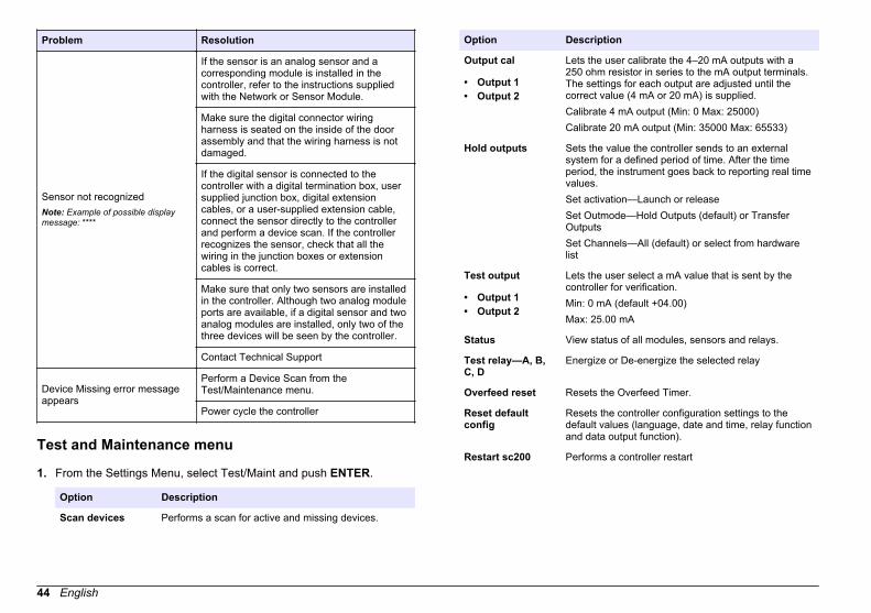
Problem Resolution
Sensor not recognizedNote: Example of possible displaymessage: ****
If the sensor is an analog sensor and acorresponding module is installed in thecontroller, refer to the instructions suppliedwith the Network or Sensor Module.
Make sure the digital connector wiringharness is seated on the inside of the doorassembly and that the wiring harness is notdamaged.
If the digital sensor is connected to thecontroller with a digital termination box, usersupplied junction box, digital extensioncables, or a user-supplied extension cable,connect the sensor directly to the controllerand perform a device scan. If the controllerrecognizes the sensor, check that all thewiring in the junction boxes or extensioncables is correct.
Make sure that only two sensors are installedin the controller. Although two analog moduleports are available, if a digital sensor and twoanalog modules are installed, only two of thethree devices will be seen by the controller.
Contact Technical Support
Device Missing error messageappears
Perform a Device Scan from theTest/Maintenance menu.
Power cycle the controller
Test and Maintenance menu
1. From the Settings Menu, select Test/Maint and push ENTER.
Option Description
Scan devices Performs a scan for active and missing devices.
Option Description
Output cal
• Output 1• Output 2
Lets the user calibrate the 4–20 mA outputs with a250 ohm resistor in series to the mA output terminals.The settings for each output are adjusted until thecorrect value (4 mA or 20 mA) is supplied.Calibrate 4 mA output (Min: 0 Max: 25000)Calibrate 20 mA output (Min: 35000 Max: 65533)
Hold outputs Sets the value the controller sends to an externalsystem for a defined period of time. After the timeperiod, the instrument goes back to reporting real timevalues.Set activation—Launch or releaseSet Outmode—Hold Outputs (default) or TransferOutputsSet Channels—All (default) or select from hardwarelist
Test output
• Output 1• Output 2
Lets the user select a mA value that is sent by thecontroller for verification.Min: 0 mA (default +04.00)Max: 25.00 mA
Status View status of all modules, sensors and relays.
Test relay—A, B,C, D
Energize or De-energize the selected relay
Overfeed reset Resets the Overfeed Timer.
Reset defaultconfig
Resets the controller configuration settings to thedefault values (language, date and time, relay functionand data output function).
Restart sc200 Performs a controller restart
44 English
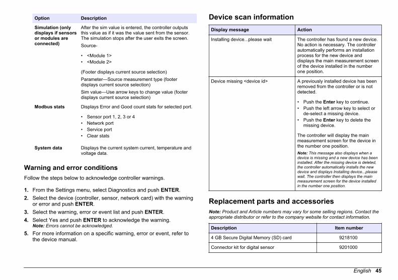
Option Description
Simulation (onlydisplays if sensorsor modules areconnected)
After the sim value is entered, the controller outputsthis value as if it was the value sent from the sensor.The simulation stops after the user exits the screen.Source-
• <Module 1>• <Module 2>
(Footer displays current source selection)Parameter—Source measurement type (footerdisplays current source selection)Sim value—Use arrow keys to change value (footerdisplays current source selection)
Modbus stats Displays Error and Good count stats for selected port.
• Sensor port 1, 2, 3 or 4• Network port• Service port• Clear stats
System data Displays the current system current, temperature andvoltage data.
Warning and error conditionsFollow the steps below to acknowledge controller warnings.
1. From the Settings menu, select Diagnostics and push ENTER.2. Select the device (controller, sensor, network card) with the warning
or error and push ENTER.3. Select the warning, error or event list and push ENTER.4. Select Yes and push ENTER to acknowledge the warning.
Note: Errors cannot be acknowledged.
5. For more information on a specific warning, error or event, refer tothe device manual.
Device scan informationDisplay message Action
Installing device...please wait The controller has found a new device.No action is necessary. The controllerautomatically performs an installationprocess for the new device anddisplays the main measurement screenof the device installed in the numberone position.
Device missing <device id> A previously installed device has beenremoved from the controller or is notdetected.
• Push the Enter key to continue.• Push the left arrow key to select or
de-select a missing device.• Push the Enter key to delete the
missing device.
The controller will display the mainmeasurement screen for the device inthe number one position.Note: This message also displays when adevice is missing and a new device has beeninstalled. After the missing device is deleted,the controller automatically installs the newdevice and displays Installing device...pleasewait. The controller then displays the mainmeasurement screen for the device installedin the number one position.
Replacement parts and accessoriesNote: Product and Article numbers may vary for some selling regions. Contact theappropriate distributor or refer to the company website for contact information.
Description Item number
4 GB Secure Digital Memory (SD) card 9218100
Connector kit for digital sensor 9201000
English 45
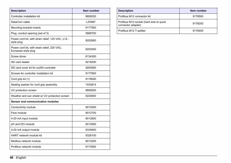
Description Item number
Controller installation kit 8806200
DataCom cable LZX887
Mounting bracket inserts 9177900
Plug, conduit opening (set of 3) 5868700
Power cord kit, with strain relief, 125 VAC, U.S.-style plug 9202900
Power cord kit, with strain relief, 230 VAC,European-style plug 9203000
Screw driver 6134300
SD card reader 9218200
SD card cover kit for sc200 controller 9200900
Screws for controller installation kit 9177800
Cord grip kit (1) 9178000
Sealing washer for cord grip assembly 1033814
UV protection screen 8809200
Weather and sun shield w/ UV protection screen 9220600
Sensor and communication modules
Conductivity module 9013000
Flow module 9012700
4-20 mA input module 9012800
pH and DO module 9012900
4-20 mA output module 9334600
HART network module kit 9328100
Modbus network module 9013200
Profibus network module 9173900
Description Item number
Profibus M12 connector kit 9178500
Profibus M12 socket (hard wire to quickconnector adapter) 9178200
Profibus M12 T-splitter 9178400
46 English


HACH COMPANY World HeadquartersP.O. Box 389, Loveland, CO 80539-0389 U.S.A.Tel. (970) 669-3050(800) 227-4224 (U.S.A. only)Fax (970) [email protected]
HACH LANGE GMBHWillstätterstraße 11D-40549 Düsseldorf, GermanyTel. +49 (0) 2 11 52 88-320Fax +49 (0) 2 11 52 [email protected]
HACH LANGE Sàrl6, route de Compois1222 VésenazSWITZERLANDTel. +41 22 594 6400Fax +41 22 594 6499
© Hach Company/Hach Lange GmbH, 2011-2013. All rights reserved. Printed in U.S.A.