HVDC Challenges in Grid Operation ByV.G.Rao Chief Manager HVDC Kolar.

1
Future multi-terminal HVDC Links J.HAFNER(ABB),et.al,” Proactive Hybrid HVDC Breakers - A key innovation for reliable HVDC grids ”,CIGRE Bologna-264 2011
LCC HVDC ±800 kV dc put in service up to 8GW ±1000 kV dc being developed in China VSC HVDC ±320kV dc operated up to 800MW Strong need for connection of offshore wind farms SC B4 investigations WG B4.52: HVDC Grid Feasibility Study, TB533 WG B4.56: Guidelines for the preparation of connection agreements for HVDC grids WG B4.57: Guide for the development of models for HVDC converters in a HVDC grid WG B4.58: Methodologies for direct voltage control in a meshed HVDC Grid WG B4/B5.59: Control and Protection of HVDC Grids JWG A3/B4.34 on DC switchgear
Achievements & main strategic directions of SC B4: HVDC & Power Electronics
A3-14 (AG01) 009 IWD

2
Determine the expected requirements specifications for different HVDC applications (system configuration, DC protection policies, etc) Clarify the requirements for fault clearing of circuit breakers
Assess the performance of existing DC switchgears (CB, DS, ES, HSGS, PBS, etc), Compare different breaker prociples such as passive resonance type, current injection type and semiconductor type
State the expected near future / under development performance specifications of DC switchgears
Clarify open issues to solve in the near future
CIGRE JWG A3/B4 meeting, Zurich Switzerland 16th-17th January, 2014
JWG A3/B4.34 DC switchgear Technical Requirements and Specifications of state-of-the-art DC switching equipment
A3-14 (AG01) 009 IWD
3
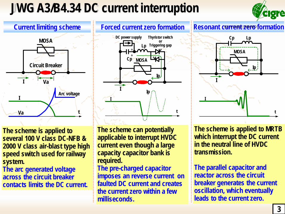
JWG A3/B4.34 DC current interruption
The scheme is applied to several 100 V class DC-NFB & 2000 V class air-blast type high speed switch used for railway system. The arc generated voltage across the circuit breaker contacts limits the DC current.
Current limiting scheme Forced current zero formation Resonant current zero formation
I Va
MOSA
Circuit Breaker
I
Va t
Arc voltage
MOSA
Lp
Cp
DC power supply
++
Ip
I
Thyristor switch or
Triggering gap
I
t
Ip
LpCp
Ip
I
MOSA
I
t
The scheme can potentially applicable to interrupt HVDC current even though a large capacity capacitor bank is required. The pre-charged capacitor imposes an reverse current on faulted DC current and creates the current zero within a few milliseconds.
The scheme is applied to MRTB which interrupt the DC current in the neutral line of HVDC transmission. The parallel capacitor and reactor across the circuit breaker generates the current oscillation, which eventually leads to the current zero.
A3-14 (AG01) 009 IWD

4
Hybrid type HVDC CB based on power electronic devices
⑤ ①
③
④
②
①
② ③
④ ⑤
②
①
③
④
⑤ ①
② ③
④
⑤
1. Fault occurrence 2. Commutate the current by Auxiliary DC Breaker 3. Disconnect the main circuit by Fast DS 4. Interrupt the current by power electronics DCCB 5. Disconnect the residual current
Development target Rated voltage: DC 320 kV Rated nominal current: DC 2000 A Rated interrupting current: DC 9 kA Interrupter: Power electronics devices Typical interrupting time: 5 ms ABB Grid Systems, Technical Paper Nov. 2012
A3-14 (AG01) 009 IWD

5
Requirements for DCCB: fault currents
Open Questions - Maximum fault currents in DC networks - Any mitigation measures (DCL) - Technical capability of various DC circuit breakers
Model of Off-shore DC network (green) and AC network (Red) Maximum fault currents S: Power electronic CB, R: Resonance type CB C. Franck, IEEE Trans. 2014 (will be published)
Close to fault --------- Remote from fault
DCCB requirements: Fault clearing time, Maximum fault current - HVDC grid is required to operate a healthy terminal to terminal continuously, when a voltage collapse at remote terminal is happened due to a fault. - Rapid clearing time is essential for DCCB, which depends on system configuration, VSC design, transmission capacity, DCL reactance, impedance of line/cable, etc.
A3-14 (AG01) 009 IWD
6
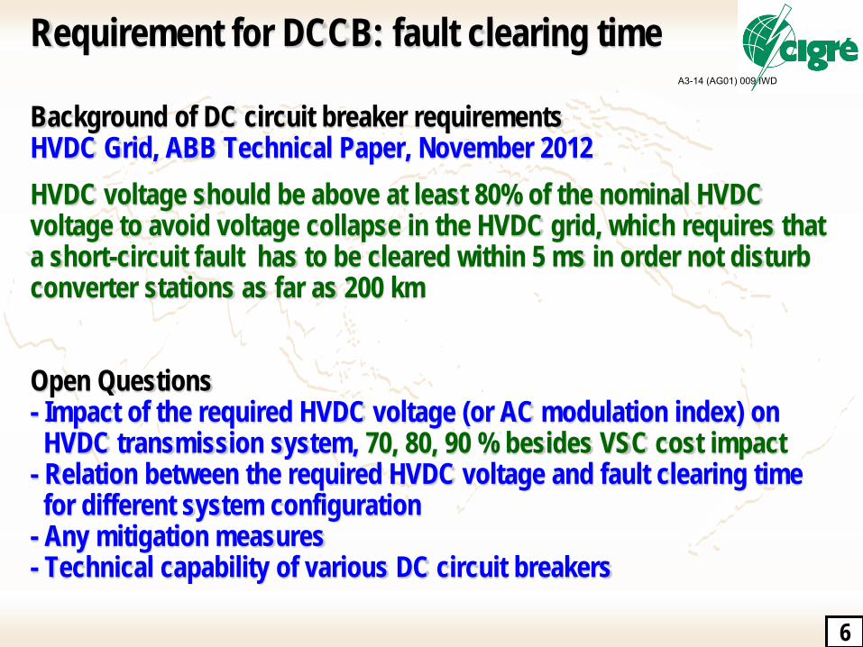
Requirement for DCCB: fault clearing time
Background of DC circuit breaker requirements HVDC Grid, ABB Technical Paper, November 2012
HVDC voltage should be above at least 80% of the nominal HVDC voltage to avoid voltage collapse in the HVDC grid, which requires that a short-circuit fault has to be cleared within 5 ms in order not disturb converter stations as far as 200 km Open Questions - Impact of the required HVDC voltage (or AC modulation index) on HVDC transmission system, 70, 80, 90 % besides VSC cost impact - Relation between the required HVDC voltage and fault clearing time for different system configuration - Any mitigation measures - Technical capability of various DC circuit breakers
A3-14 (AG01) 009 IWD
7
DCCB
IDC
VDC Fault
DCDS
IDC
VDC Fault
IDC
fault
IDC
fault
VDC
fault
VDC
fault
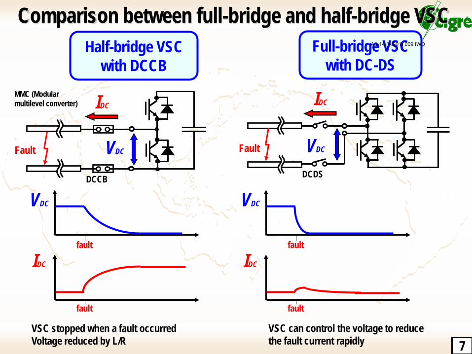
VSC stopped when a fault occurred Voltage reduced by L/R
VSC can control the voltage to reduce the fault current rapidly
Half-bridge VSC with DCCB
Full-bridge VSC with DC-DS
Comparison between full-bridge and half-bridge VSC
MMC (Modular multilevel converter)
A3-14 (AG01) 009 IWD
8
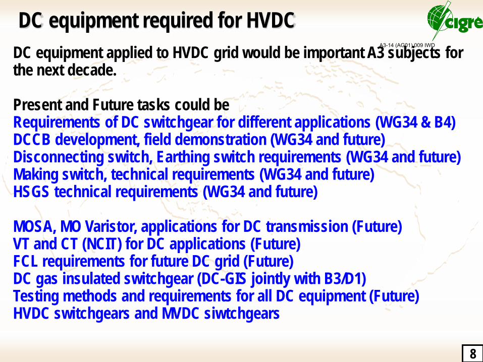
DC equipment required for HVDC DC equipment applied to HVDC grid would be important A3 subjects for the next decade. Present and Future tasks could be Requirements of DC switchgear for different applications (WG34 & B4) DCCB development, field demonstration (WG34 and future) Disconnecting switch, Earthing switch requirements (WG34 and future) Making switch, technical requirements (WG34 and future) HSGS technical requirements (WG34 and future) MOSA, MO Varistor, applications for DC transmission (Future) VT and CT (NCIT) for DC applications (Future) FCL requirements for future DC grid (Future) DC gas insulated switchgear (DC-GIS jointly with B3/D1) Testing methods and requirements for all DC equipment (Future) HVDC switchgears and MVDC siwtchgears
A3-14 (AG01) 009 IWD