SBRT Simulation, Planning, and Contouring – the Team Approach
55
SBRT Simulation, Planning, and Contouring: The Team Approach Jessica Stanulus BS, RT(T), CMD
Transcript of SBRT Simulation, Planning, and Contouring – the Team Approach

SBRTSimulation, Planning, and
Contouring:The Team Approach
Jessica Stanulus BS, RT(T), CMD

Stereotactic body radiation therapy (SBRT), or stereotactic ablative radiotherapy (SABR), is a radiotherapy treatment technique used to deliver a high dose per fraction in a few fractions to a target with a high degree of 3D targeting accuracy
• 10-20 Gy per fraction• 3-5 fractions
• Target is typically smaller than conventional RT (<5cm diameter)
The goal of SBRT treatment is to “ablate” tissues within the PTV

Clinical Trials show:• Improved local control rates• Improved long-term survival• Comparable to surgical results in certain cases without the risks
associated with surgery
• 0631 Spine• 0813 & 0915 Lung• 0438 Liver


SimulationPositioning and immobilization should be done in a manner that allows
planners to have as much flexibility as possible for a given tumor site.
Patients arms should be raised, placed in a comfortable position, and immobilized with Vac-loc support or other methods.
Linking the patient to the treatment couch through indexing is desirable for setting patients up routinely in the same position. This is generally accomplished by indexing SBRT-style body frames to the linac couch.

It’s all about the motion:Respiratory motion impacts many aspects of SBRT treatment design through changing position, shape, and size of tumors and normal tissue. There are several approaches to assessing motion• flourographic imaging• Breath hold CT scans (inspiration, expiration)• 4DCT
Tumor motion is typically greater near the diaphragm and periphery of the lung

Motion managementCompression techniques (compression pad or belt)Deep inspiration breath hold (DIBH)Real-time gating• implanted fiducial tracking• External/surface surrogates (RPM, VisionRT)• Spirometry

Gating on the treatment machine whether it be Spirometry, Calypso with a RF grid, or a Motion management innerface, it all lengthens the time on the table for treatment
Sometimes with Calypso the RF attenuation can’t be detected or the marker could move
Using and external monitor MMI, that motion is detecting up and down motion whereas the motion in the lung is sup/inf
When doing VMAT with gating, it’s hard once the beam stops at certain angles to get the gantry back going—there is wobble in the gantry/needs inertia to get going again
All things for further discussion


Normal scan MIP
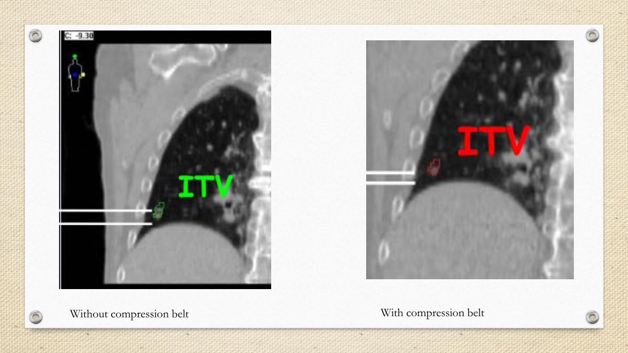
Without compression belt With compression belt

Sources of Error in 4DCT
Irregular patient breathing-you want regular and reproducible breathing by coaching
CT image reconstruction algorithm
Prior to the start of simulations, the patients should be made familiar with the equipment and it’s purpose. You really want to coach the patient and also evaluate the patient to see if the patient can hold their breath and for how long for breath hold exams/treatments etc.

Views of CT scans of the same patient taken during FB and with respitory gated scanning at exhale
Slide taken from AAPM Report No. 91


Contouringo Review 4DCT images for sufficient scan quality for contouring
o Multi-modality imaging may be used for target and OAR delineation (spinal cord)
o Ensure registration of images is performed so that the greatest agreement is near the area of concern. For spine SBRT, focus on registration of vertebral bodies at the level of interest. For soft tissue targets, the registration may need to be focused in the vicinity of the soft tissue tumor.
o SBRT planning introduces some structures that are not routinely contoured for conventional fractionated cases. Oftentimes the contours depend on the location of the tumor to be treated.
o Accurate contouring is important in order to employ the dose constraints properly from RTOG protocols

• Spinal Cord• Esophagus• Brachial Plexus• Proximal Trachea• Heart• Whole lung• Skin (outer 0.5cm of the body surface)• Trachea and Proximal Bronchial Tree
Proximal Bronchial Tree Figure 2 - Zone of proximal bronchial tree. Defined as a volume 2 cm in all directions around the proximal bronchial tree (carina, right and left main bronchi, right and left upper lobe bronchi, intermedius bronchus, right middle lob bronchus, lingular bronchus right and left lower lobe bronchi.
• Great Vessels• Rib• Chest-wall• Kidney• Trachea and Airway• Larynx and Pharynx• Insert appropriate couch structures for treatment

Skin Ring! 5mm ring inside the body to account for skin dose

o Structure for R100 calculationCreate after plan dose has been calculated. Convert the 100% isodose cloud into a structureNeed volume of this structure for calculation of R100
o Structure for R50 calculationCreate after plan dose has been calculated. Convert the 50% isodose cloud into a structureNeed volume for calculation of R50
o D2cmCreate by using Eclipse’s cropping toolCrop PTV from BODY with a 2 cm margin
o 105% outside of PTVCreate after plan dose has been calculated. Convert 105% (of prescription dose) to a structureCreate structure by subtracting PTV from the 105% structure


Conformal high dose• R100 = (100% dose volume)/(PTV volume)
Compact intermediate dose• R50 = (50% of prescription dose volume)/(PTV volume)
Low dose spillage: D2cm• Maximum point dose at 2 cm from PTV
105% outside of PTV• Any dose > 105% of the prescription dose should be primarily contained within the PTV itself and not within surrounding normal tissues.

- RTOG conformality table.


Sometimes as Dosimetrists we are left between these two options:

PlanningPrescription dose
Ablative doses are used in SBRT/SABR treatment plans because these dose levels overwhelm cellular repair mechanisms for any type of cell. This is beneficial in terms of annihilating cancer, however, it requires that special attention be given to normal tissue in the vicinity of the high dose region. Hypoxic regions may be present within tumor volumes and typically require higher dose levels to eradicate.

Cord and Brachial Plexus Tolerance Dose met95% PTV Coverage99% of PTV is covered by 90% of dosehot spot within PTVD2cmR50R100Normal StructuresMinimum of 10 Beams or DCA plan or IMRT plan w static fields or arcs
SBRT Planning Guide

Dose distribution goals
The ablative dose concept is generally employed by encouraging target dose heterogeneity meaning that the dose is typically higher in the target center (purposefully designed hotspot) and there is a dose gradient from the center toward the target edges (not typical of conventional plans which seek homogeneous target dose).
Steep slope for dose gradient outside PTV
Sharp dose fall off

Planning technique
Forward planning: 3d static beams or dynamic conformal arcs Inverse planning: IMRT/VMAT

Regardless of planning technique, always inspect all beam/arc angles to ensure that they will be deliverableEnsure that body/external contour is accurate and evaluate for collision potentialView field entry shapes on patient’s 3d modelTry to avoid beams entering though unstable anatomy such as arms, breast folds, cut-off ct data, etc.
Static beams:8-12 beamsSpread out around patient trying to avoid opposing beamsAvoid having beams pass directly through critical structures (avoid entrance side prior to PTV)Couch angles of 20-30° are usually deliverable (beware of arm position and immobilization devices)
Figure 6 – UT Southwestern gantry and couch combinations for right- and left-sided lung tumors.

Figure 1 - 3D representation UTSouthwestern beam angles.

Dynamic conformal arcs (DCA)o Spread out around patient (generally non-coplanar arcs).
Typically able to deliver 10-25° off transverse plane (couch rotations). o Some arcs may be split into smaller arcs to allow for greater control of dose distribution through weighting
Fast planning and deliveryLimited dose shaping but can provide a steep fall off

IMRT/VMATNot recommended for small targets with significant motionUsually reserved for target volumes >20ccMay be necessary for sparing critical structuresCan have coplanar or non-coplanar arcsCollimator rotation of 15-45 degrees
Maximum dose must be within the PTV95% of the target volumes (PTV) is conformally covered by the prescription isodose surfaceHigh dose spillage: The cumulative volume of all tissue outside the PTV receiving a dose >105% of prescription dose should be no more than 15% of the PTV volume

DCA vs. VMAT
DCA− Forward planned
− Segments to conform
to target and avoid OARs
− Low MU for delivered dose
− Constant dose rate
VMAT– Inverse Planned
– Segments to mimic intensity maps based on user defined goals
– Higher MU for delivered dose
– Variable dose rate

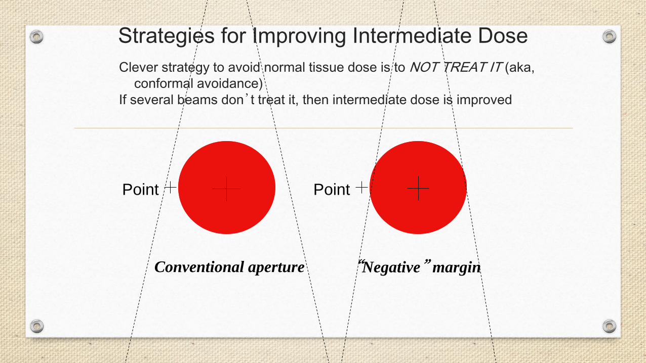
Strategies for Improving Intermediate Dose
Conventional aperture “Negative” margin
Point Point
Clever strategy to avoid normal tissue dose is to NOT TREAT IT (aka, conformal avoidance)
If several beams don’t treat it, then intermediate dose is improved

Dose calculation
Plan off appropriate CT image set (free breathing, MIP, Average intensity projection)Heterogeneity corrections use acceptable correction algorithmsCalculation grid size TG-101 recommends using 2 mm or finer grid size (we use 1mm)
If your clinic will allow it, allow plenty of time between simulation and treatment to gather all imaging data, evaluate motion, create a plan, evaluate a plan, QA plan, etc

“Dry Runs” are highly recommended for SBRT if non coplanar beams/arcs are usedTreatment verification, reproduce setup and verify isocenterClinically mode up each tx field and check beam clearance, check for any interlocks such as any potential MU problems >1000 mu for any single field is beyond machine capability for non-srs beams or MLC interlock could mean corruption of MLC files (undeliverable beam)

Imaging:CBCT recommended imaging technique for soft tissue tumorsExacTrac/OBI imaging used for spine SBRT
Doctor must be present for every treatment fraction and Physics should be available for every treatment


There is no magic wand, but here are some things to think about and experiment with….


Optimization resolution is a parameter that controls the number of points that are placed inside a structure for the purpose of dose evaluation and objective function calculation when optimizing a IMRT or VMAT plan
It’s value is in mm and is defined as space in between points. You will want to lower your value in the optimizer to get more points to get a higher resolution
In contouring, you can also set your structure to a high accuracy structure. (As a tip, once you set to a high accuracy structure, your Boolean operator will not function)


Plan Challenge tips for SBRT:
• Grid Size of 1mm• High density structures (Tip: can’t use boolean tool after you change)• Resolution in optimizer (For high resolution, decrease your resolution in optimizer its space in between points
value in mm)• NTO Function (Understand how to use properly)• Using a ring such as Body-PTV+2mm/2cm• Artifact of seeds• Try to keep MU’s to 2x’s daily dose (helps with modulation)• Collimator angles• Pause optimizer often• KISS principle• Know how your optimizer works• Small adjustments can bring big rewards• Don’t overcomplicate the process• Common sense is your best friend