
SBM 100 - electroind.com
60
SBM 100 3-PHASE ENERGY SUBMETER WITH DEMAND Instruction Manual Doc # E104720 V1.03 January 21, 2005 1800 Shames Drive Westbury, New York 11590 Electro Industries/GaugeTech Tel: 516-334-0870 X Fax: 516-338-4741 E-mail:[email protected] X www.electroind.com “The Leader in Web Accessed Power Monitoring and Control”
Transcript of SBM 100 - electroind.com
SBM 100
3-PHASE ENERGY SUBMETER WITH DEMAND
Instruction Manual Doc # E104720 V1.03 January 21, 2005
1800 Shames Drive Westbury, New York 11590
Electro Industries/GaugeTech
Tel: 516-334-0870 Fax: 516-338-4741 E-mail:[email protected] www.electroind.com
“The Leader in Web Accessed Power Monitoring and Control”

Customer Service and Support Customer service and support is available 9:00 am to 4:30 pm EST, Monday through Friday. Please have the model, serial number and a detailed problem description available. If the problem concerns a particular reading, please have all meter readings available. When returning any merchandise to EIG, a return authorization number is required. For customer or technical assistance, repair or calibration, call: 516-334-0870 or fax 516-338-4741. Product Warranty Electro Industries/GaugeTech warrants all products to be free from defects in material and workmanship for a period of four years from the date of shipping. During the warranty period, we will, at our option, either repair or replace any product that proves to be defective. To exercise this warranty, fax or call our customer service department. You will receive prompt assistance and return instructions. Send the instrument, transportation prepaid, to EIG at 1800 Shames Drive, Westbury, NY 11590. Repairs will be made and the instrument will be returned. Limitation of Warranty This warranty does not apply to defects resulting from unauthorized modification, misuse or use for any reason other than electrical power monitoring. OUR PRODUCTS ARE NOT TO BE USED FOR PRIMARY OVER-CURRENT PROTECTION. ANY PROTECTION FEATURE IN OUR PRODUCTS IS TO BE USED FOR ALARM OR SECONDARY PROTECTION ONLY. THIS WARRANTY IS IN LIEU OF ALL OTHER WARRANTIES, EXPRESSED OR IMPLIED, INCLUDING ANY IMPLIED WARRANTY OF MERCHANABILITY OR FITNESS FOR A PARTICULAR PURPOSE. ELECTRO INDUSTRIES/GAUGETECH SHALL NOT BE LIABLE FOR ANY PENAL, INDIRECT, SPECIAL OR CONSEQUENTIAL DAMAGES ARISING FROM ANY AUTHORIZED OR UNAUTHORIZED USE OF ANY ELECTRO INDUSTRIES/GAUGETECH PRODUCT. LIABILITY SHALL BE LIMITED TO THE ORIGINAL COST OF THE PRODUCT SOLD. Statement of Calibration Our instruments are inspected and tested in accordance with specifications published by Electro Industries/GaugeTech. The accuracy and a calibration of our instruments are traceable to the National Institute of Standards and Technology through equipment that is calibrated at planned intervals by comparison to certified standards. Disclaimer The information presented in this publication has been carefully checked for reliability; however, no responsibility is assumed for inaccuracies. The information contained in this document is subject to change without notice.
i
TABLE OF CONTENTS
CHAPTER 1 AC POWER MEASUREMENT 1
Section 1.1 Single Phase System 1 1.2 Three Phase System 2 1.3 Consumption, Demand, and Power Factor Losses 3 1.4 Waveform and Harmonics 3
CHAPTER 2 MECHANICAL INSTALLATION 5 Face of the SBM 100 with lower cover removed 5 Relay detail 5 Mounting detail for SBM 100 6
CHAPTER 3 ELECTRICAL INSTALLATION 7 Section 3.1 Connecting the Current Circuit 7
3.2 CT Connection 7 3.3 Connecting the Voltage Circuit 7 3.4 Selecting the Voltage Fuses 7 3.5 Connection to the Main Power Supply 8 3.6 Electrical Connection Installation 8
Three-Phase, Three-Wire Delta with Direct Voltage and CTs 9 Three-Phase, Three-Wire Delta with 2 CTs and 2 PTs 10 Three-Phase, Three-Wire Open Delta with three CT's and two PTs 11 Three-Phase, Four-Wire System Wye with Direct Voltage and CTs 12 Three-Phase, Four-Wire System Wye with CTs and PTs 13 Three-Phase, Four Wye 2-1/2 Element with CTs and PTs 14
3.7 Relays, Protection and Pulse Output 15
CHAPTER 4 COMMUNICATION INSTALLATION 17 Wiring diagram of SBM 100. 17 RS-485 Communication Connection 18
Section 4.1 RS-485 19 4.2 Network of Instruments and Long Distance Communication 19
Modem Connected to Computer 19 Modem Connected to the Device 20
CHAPTER 5 SBM 100 OVERVIEW 21 Section 5.1 The SBM 100 Meter System 21 5.2 Product Features 21 5.3 Accessing KW, KWD, KWH 22
5.4 Resetting KWD/KWH Readings 22 Unprotected Reset 22 Protected Reset 23
5.5 Accessing Set Limits LM1/LM2 24 5.6 Printing Operating Data 25 5.7 Printing Programming Data 25 5.8 Firmware Version/LED Test 26
Electro Industries/GaugeTech Doc # E104720 V1.03 iii

CHAPTER 6 PROGRAMMING OVERVIEW 27 Section 6.1 How to Use this Portion of the Manual 27
6.2 Switch Packs 27 6.3 Programming Mode Data Entry 28 6.4 Standard Numeric Data Entry 28
CHAPTER 7 ENTERING THE PROGRAMMING MODE 29 Section 7.1 Password Entry 29
CHAPTER 8 PROGRAMMING GROUP 0 31 Group 0 Programming Format 31
Section 8.1 Group 0, Function 0 - The Integration Interval 31 8.2 Group 0, Function 1 - The Meter Address 32 8.3 Group 0, Function 2 - Communication Baud Rate 32 8.4 Group 0, Function 3 - System Configuration (Programming Options) 33
System Configuration – Switch Features 34 8.5 Group 0, Functions 4 and 5 - Time Delay for Relays 1 and 2 35
CHAPTER 9 PROGRAMMING GROUP 1 37 Group 1 Programming Format 37
Section 9.1 Group 1, Functions 0 - Scale Selection for Watts 37
CHAPTER 10 PROGRAMMING GROUP 2 41 Group 2 Progrmming Format 41
Section 10.1 Calibration Requirements 41 10.2 Group 2, Functions 0-1 - High and Low End Watts Calibration 42
CHAPTER 11 PROGRAMMING GROUP 3 45 Group 3 Programming Format 45
Section 11.1 Group 3, Functions 0-1 - High and Low Correction Ratios 45
CHAPTER 12 PROGRAMMING GROUP 5 47 Example of LMT1/LMT2 Set Limits 47
Section 12.1 Trip Relay 47 Group 5 Programming Format 47
12.2 Group 5, Functions 0-1 - LMT1/LMT2 Set Limits 47
CHAPTER 13 EXITING THE PROGRAMMING MODE 51
APPENDIX A Reserved Groups, Functions and Packs i APPENDIX B Quick Reference i APPENDIX C Open Delta System Installation Programming i APPENDIX D Modbus Mapping for SBM 100 i
iv Electro Industries/GaugeTech Doc # E104720 V1.03
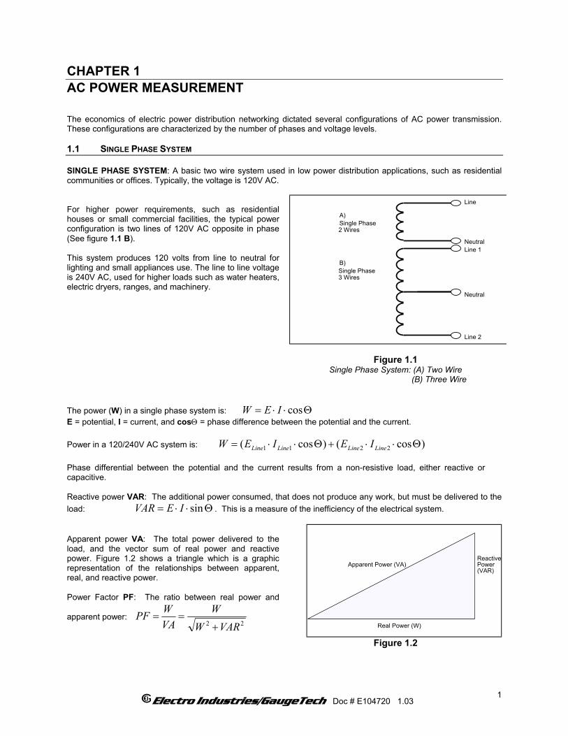
CHAPTER 1 AC POWER MEASUREMENT The economics of electric power distribution networking dictated several configurations of AC power transmission. These configurations are characterized by the number of phases and voltage levels. 1.1 SINGLE PHASE SYSTEM SINGLE PHASE SYSTEM: A basic two wire system used in low power distribution applications, such as residential communities or offices. Typically, the voltage is 120V AC. For higher power requirements, such as residential houses or small commercial facilities, the typical power configuration is two lines of 120V AC opposite in phase (See figure 1.1 B). This system produces 120 volts from line to neutral for lighting and small appliances use. The line to line voltage is 240V AC, used for higher loads such as water heaters, electric dryers, ranges, and machinery.
Line
Neutral
Line 2
Line 1
Neutral
A)Single Phase2 Wires
B)Single Phase3 Wires
Figure 1.1
Single Phase System: (A) Two Wire (B) Three Wire
The power (W) in a single phase system is: W Θ⋅⋅= cosIEE = potential, I = current, and cosΘ = phase difference between the potential and the current. Power in a 120/240V AC system is: )cos()cos( 2211 Θ⋅⋅+Θ⋅⋅= LineLineLineLine IEIEW
Phase differential between the potential and the current results from a non-resistive load, either reactive or capacitive. Reactive power VAR: The additional power consumed, that does not produce any work, but must be delivered to the load: . This is a measure of the inefficiency of the electrical system. Θ⋅⋅= sinIEVAR
Apparent power VA: The total power delivered to the load, and the vector sum of real power and reactive power. Figure 1.2 shows a triangle which is a graphic representation of the relationships between apparent, real, and reactive power. Power Factor PF: The ratio between real power and
apparent power: 22 VARW
WVAWPF
+==
Apparent Power (VA)
Real Power (W)
ReactivePower(VAR)
Figure 1.2
Electro Industries/GaugeTech Doc # E104720 1.03
1
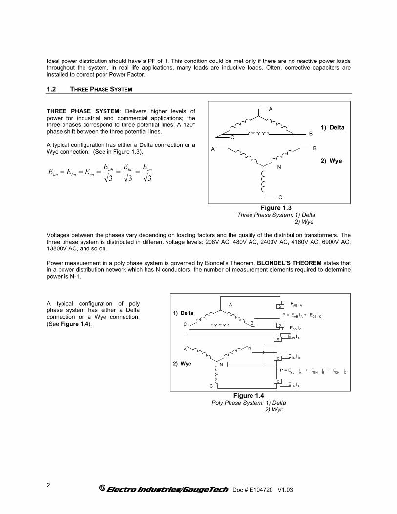
Ideal power distribution should have a PF of 1. This condition could be met only if there are no reactive power loads throughout the system. In real life applications, many loads are inductive loads. Often, corrective capacitors are installed to correct poor Power Factor. 1.2 THREE PHASE SYSTEM THREE PHASE SYSTEM: Delivers higher levels of power for industrial and commercial applications; the three phases correspond to three potential lines. A 120° phase shift between the three potential lines. A typical configuration has either a Delta connection or a Wye connection. (See in Figure 1.3).
333acbcab
cnbnanEEEEEE =====
B
A
C
N
A B
C
1) Delta
2) Wye
Figure 1.3
Three Phase System: 1) Delta 2) Wye
Voltages between the phases vary depending on loading factors and the quality of the distribution transformers. The three phase system is distributed in different voltage levels: 208V AC, 480V AC, 2400V AC, 4160V AC, 6900V AC, 13800V AC, and so on. Power measurement in a poly phase system is governed by Blondel's Theorem. BLONDEL'S THEOREM states that in a power distribution network which has N conductors, the number of measurement elements required to determine power is N-1. A typical configuration of poly phase system has either a Delta connection or a Wye connection. (See Figure 1.4).
N
A B
C
2) Wye
X E ICN C
X
X
P = E I + E I + E IAN BN CN
E IBN B
E IAN A
B
A
C
1) Delta
X
X
E ICB C
E IAB A
P = E IAB A + E ICB C
A B C
Figure 1.4
Poly Phase System: 1) Delta 2) Wye
Electro Industries/GaugeTech Doc # E104720 V1.03
2

1.3 CONSUMPTION, DEMAND AND POWER FACTOR LOSSES The total electric energy usage over a period of time is the consumption WH. CONSUMPTION: W = instantaneous power T = time in hours TWH ⋅=
Typically, the unit in which consumption is specified is the kilowatt-hour (KWH). KILOWATT-HOUR : one thousand watts consumed over one hour. Utilities use the WH equation to determine the overall consumption in a billing period. DEMAND: Average energy consumed over a specified time interval. The interval is determined by the utility; typically, 15 or 30 minutes. The utility measures the maximum demand over a billing period. This measurement exhibits a deviation from average consumption that may force the utility to provide generating capacity to satisfy a high maximum consumption demand. The highest average demand is retained in the metering until the demand level is reset. POOR POWER FACTOR: Results in reactive power consumption. Transferring reactive power over a distribution network causes energy loss. To force consumers to correct their Power Factor, utilities monitor reactive power consumption and penalize the user for poor Power Factor. This is becoming an increasing problem. 1.4 WAVEFORM AND HARMONICS Ideal power distribution has sinusoidal wave forms on voltages and currents. In real life application, where inverters, computers, and motor controls are used, distorted wave forms are generated. Those distortions consist of harmonics of the fundamental frequency. SINUSOIDAL WAVEFORM: )sin( tA ⋅⋅ ω
DISTORTED WAVEFORM: ...)sin()sin()sin()sin( 332211 +⋅⋅+⋅⋅+⋅⋅+⋅⋅ tAtAtAtA ωωωω
TOTAL HARMONIC DISTORTION (THD):
100% ⋅=ignalndamentalSRMSoftheFu
gnalstortionSiHarmonicDiRMSofTotalofTHD
HARMONIC DISTORTION: A destructive force in power distribution systems. It creates safety problems, shortens the life span of distribution transformers, and interferes with the operation of electronic devices.
Electro Industries/GaugeTech Doc # E104720 V1.03
3

Electro Industries/GaugeTech Doc # E104720 V1.03
4
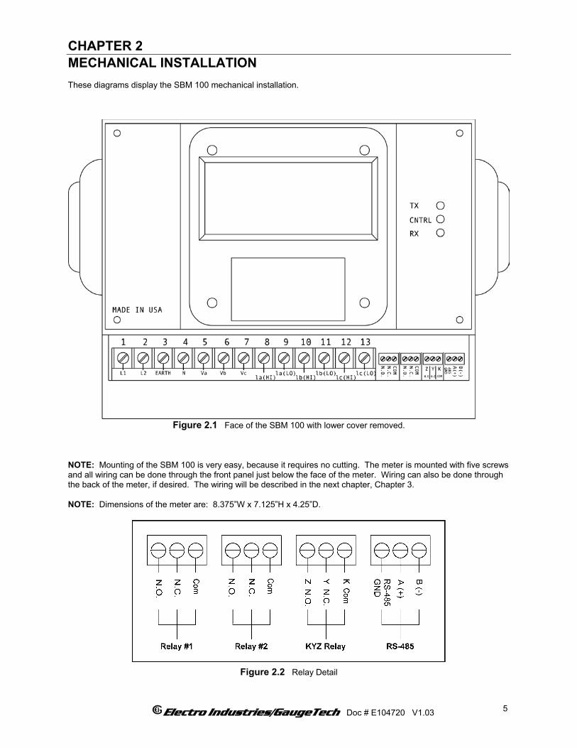
CHAPTER 2 MECHANICAL INSTALLATION These diagrams display the SBM 100 mechanical installation.
Figure 2.1 Face of the SBM 100 with lower cover removed.
NOTE: Mounting of the SBM 100 is very easy, because it requires no cutting. The meter is mounted with five screws and all wiring can be done through the front panel just below the face of the meter. Wiring can also be done through the back of the meter, if desired. The wiring will be described in the next chapter, Chapter 3. NOTE: Dimensions of the meter are: 8.375”W x 7.125”H x 4.25”D.
Figure 2.2 Relay Detail
Electro Industries/GaugeTech Doc # E104720 V1.03
5

5.25
3.75
3.75
Figure 2.3 Mounting Detail for SBM 100.
NOTE: Mounting of the SBM 100 is very easy, because it requires no cutting. The meter is mounted with five screws as shown and all wiring can be done through a front panel just below the face of the meter. All dimensions in the figure above are in inches.
Electro Industries/GaugeTech Doc # E104720 V1.03
6
Electro Industries/GaugeTech Doc # E104720 V1.03 7
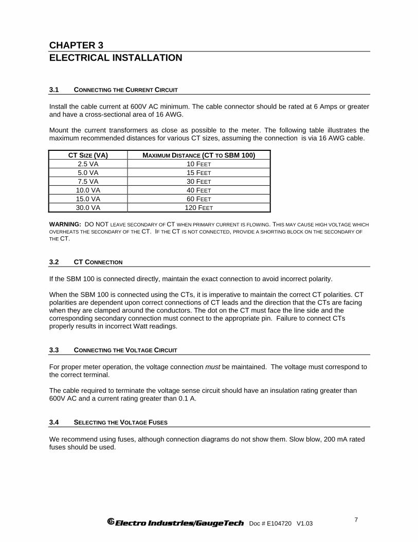
CHAPTER 3 ELECTRICAL INSTALLATION 3.1 CONNECTING THE CURRENT CIRCUIT Install the cable current at 600V AC minimum. The cable connector should be rated at 6 Amps or greater and have a cross-sectional area of 16 AWG. Mount the current transformers as close as possible to the meter. The following table illustrates the maximum recommended distances for various CT sizes, assuming the connection is via 16 AWG cable.
CT SIZE (VA) MAXIMUM DISTANCE (CT TO SBM 100) 2.5 VA 10 FEET 5.0 VA 15 FEET 7.5 VA 30 FEET
10.0 VA 40 FEET 15.0 VA 60 FEET 30.0 VA 120 FEET
WARNING: DO NOT LEAVE SECONDARY OF CT WHEN PRIMARY CURRENT IS FLOWING. THIS MAY CAUSE HIGH VOLTAGE WHICH OVERHEATS THE SECONDARY OF THE CT. IF THE CT IS NOT CONNECTED, PROVIDE A SHORTING BLOCK ON THE SECONDARY OF THE CT. 3.2 CT CONNECTION If the SBM 100 is connected directly, maintain the exact connection to avoid incorrect polarity. When the SBM 100 is connected using the CTs, it is imperative to maintain the correct CT polarities. CT polarities are dependent upon correct connections of CT leads and the direction that the CTs are facing when they are clamped around the conductors. The dot on the CT must face the line side and the corresponding secondary connection must connect to the appropriate pin. Failure to connect CTs properly results in incorrect Watt readings. 3.3 CONNECTING THE VOLTAGE CIRCUIT For proper meter operation, the voltage connection must be maintained. The voltage must correspond to the correct terminal. The cable required to terminate the voltage sense circuit should have an insulation rating greater than 600V AC and a current rating greater than 0.1 A. 3.4 SELECTING THE VOLTAGE FUSES We recommend using fuses, although connection diagrams do not show them. Slow blow, 200 mA rated fuses should be used.
Electro Industries/GaugeTech Doc # E104720 V1.03
8
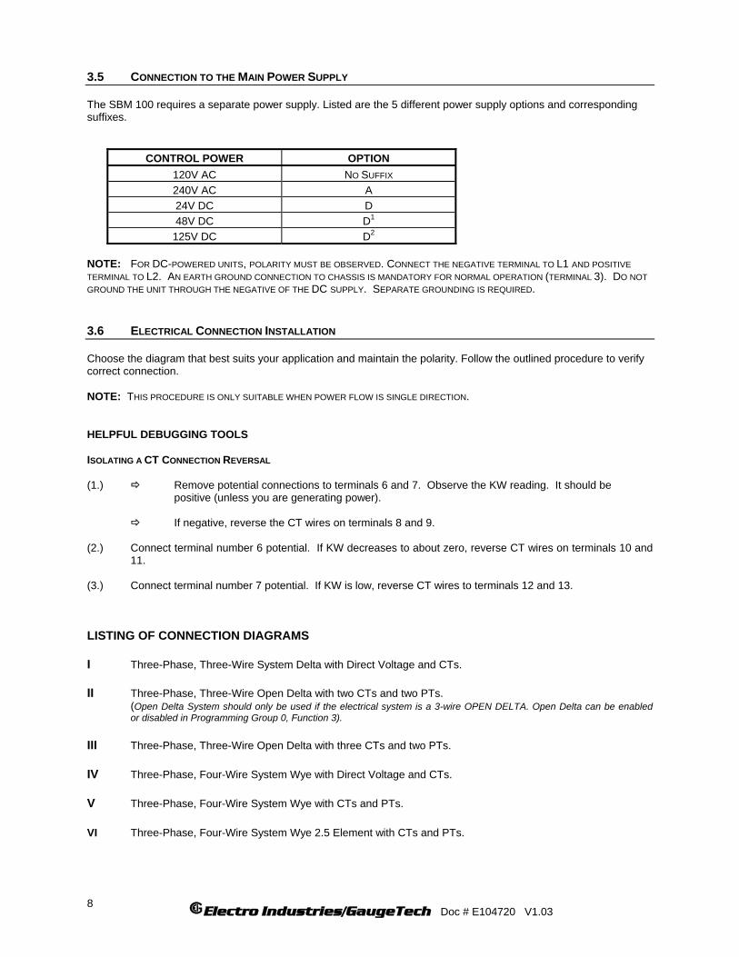
3.5 CONNECTION TO THE MAIN POWER SUPPLY The SBM 100 requires a separate power supply. Listed are the 5 different power supply options and corresponding suffixes.
CONTROL POWER OPTION 120V AC NO SUFFIX 240V AC A 24V DC D 48V DC D1
125V DC D2 NOTE: FOR DC-POWERED UNITS, POLARITY MUST BE OBSERVED. CONNECT THE NEGATIVE TERMINAL TO L1 AND POSITIVE TERMINAL TO L2. AN EARTH GROUND CONNECTION TO CHASSIS IS MANDATORY FOR NORMAL OPERATION (TERMINAL 3). DO NOT GROUND THE UNIT THROUGH THE NEGATIVE OF THE DC SUPPLY. SEPARATE GROUNDING IS REQUIRED. 3.6 ELECTRICAL CONNECTION INSTALLATION Choose the diagram that best suits your application and maintain the polarity. Follow the outlined procedure to verify correct connection. NOTE: THIS PROCEDURE IS ONLY SUITABLE WHEN POWER FLOW IS SINGLE DIRECTION. HELPFUL DEBUGGING TOOLS ISOLATING A CT CONNECTION REVERSAL (1.) Remove potential connections to terminals 6 and 7. Observe the KW reading. It should be positive (unless you are generating power). If negative, reverse the CT wires on terminals 8 and 9. (2.) Connect terminal number 6 potential. If KW decreases to about zero, reverse CT wires on terminals 10 and 11. (3.) Connect terminal number 7 potential. If KW is low, reverse CT wires to terminals 12 and 13.
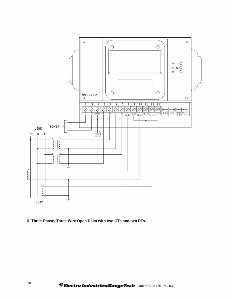
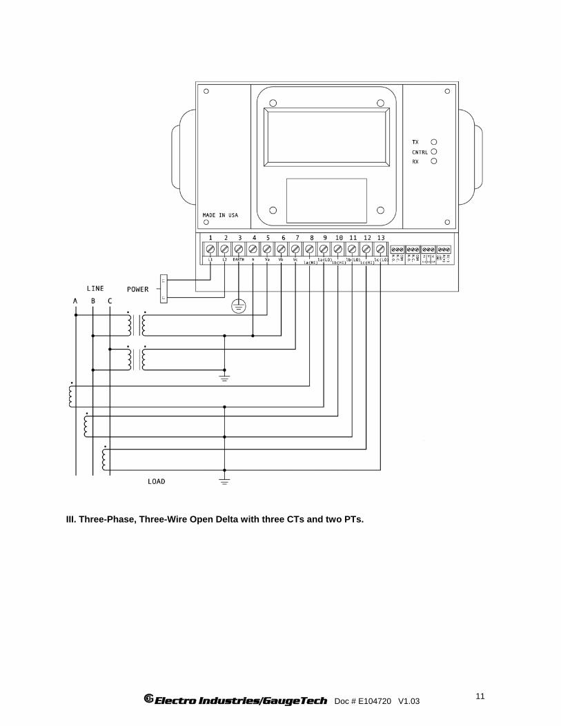
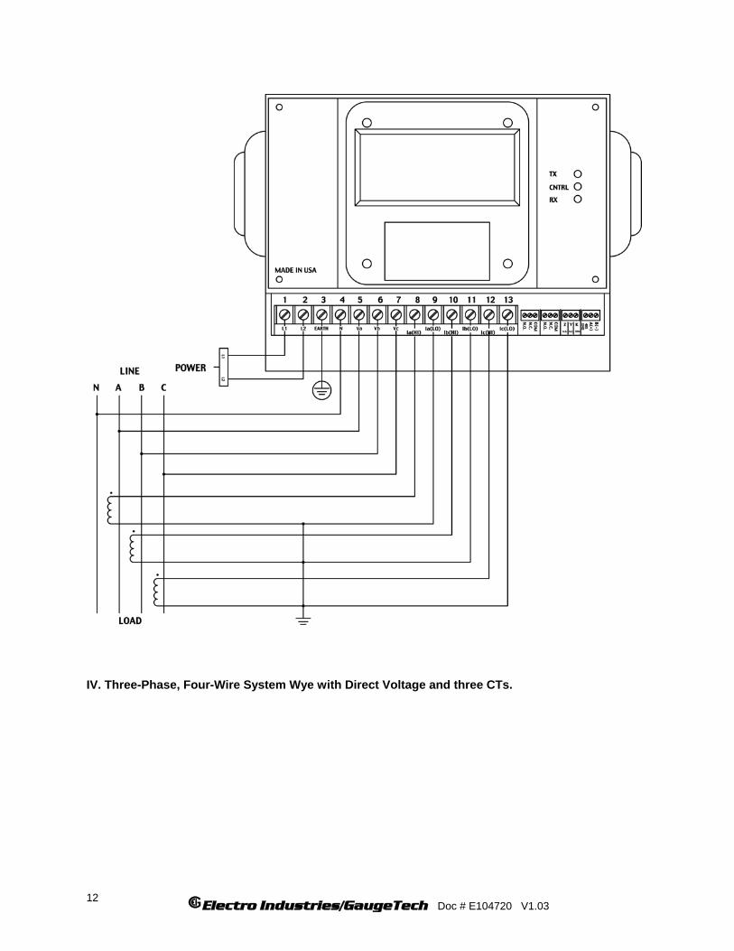
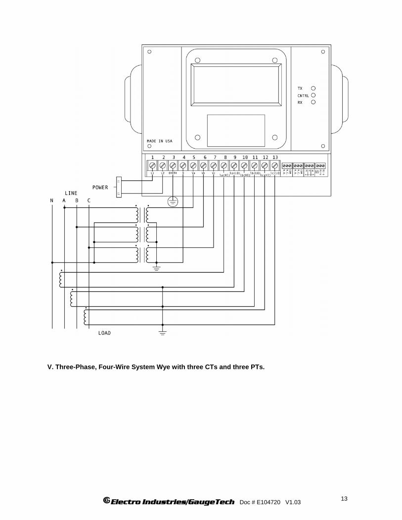
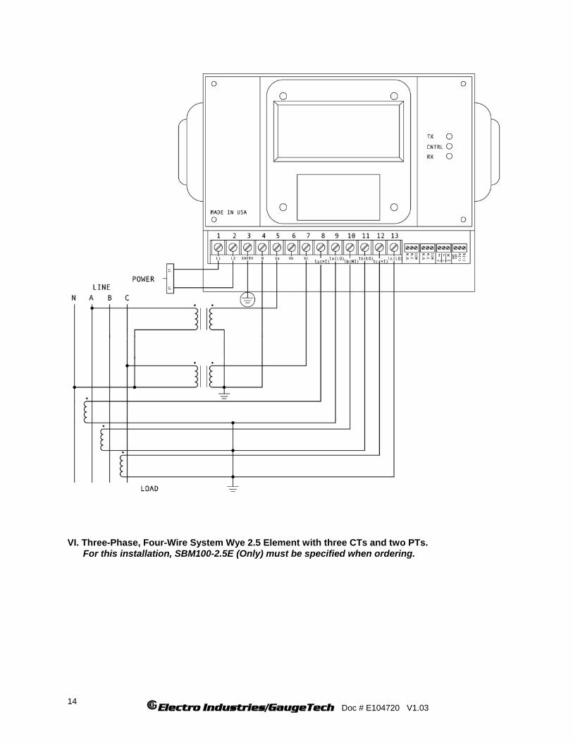
LISTING OF CONNECTION DIAGRAMS I Three-Phase, Three-Wire System Delta with Direct Voltage and CTs. II Three-Phase, Three-Wire Open Delta with two CTs and two PTs. (Open Delta System should only be used if the electrical system is a 3-wire OPEN DELTA. Open Delta can be enabled or disabled in Programming Group 0, Function 3). III Three-Phase, Three-Wire Open Delta with three CTs and two PTs. IV Three-Phase, Four-Wire System Wye with Direct Voltage and CTs. V Three-Phase, Four-Wire System Wye with CTs and PTs. VI Three-Phase, Four-Wire System Wye 2.5 Element with CTs and PTs.
Electro Industries/GaugeTech Doc # E104720 V1.03 9
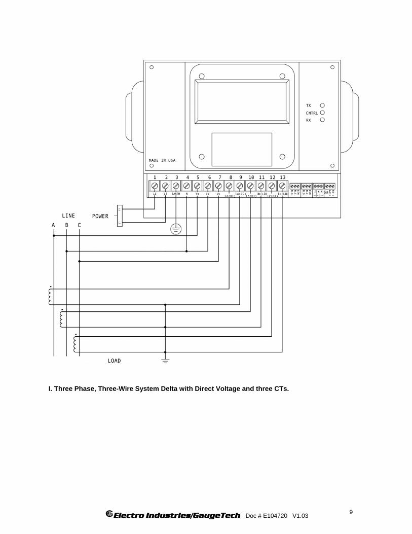
I. Three Phase, Three-Wire System Delta with Direct Voltage and three CTs.
Electro Industries/GaugeTech Doc # E104720 V1.03
10
II. Three-Phase, Three-Wire Open Delta with two CTs and two PTs.
Electro Industries/GaugeTech Doc # E104720 V1.03 11
III. Three-Phase, Three-Wire Open Delta with three CTs and two PTs.
Electro Industries/GaugeTech Doc # E104720 V1.03
12
IV. Three-Phase, Four-Wire System Wye with Direct Voltage and three CTs.
Electro Industries/GaugeTech Doc # E104720 V1.03 13
V. Three-Phase, Four-Wire System Wye with three CTs and three PTs.
Electro Industries/GaugeTech Doc # E104720 V1.03
14
VI. Three-Phase, Four-Wire System Wye 2.5 Element with three CTs and two PTs. For this installation, SBM100-2.5E (Only) must be specified when ordering.
Electro Industries/GaugeTech Doc # E104720 V1.03 15
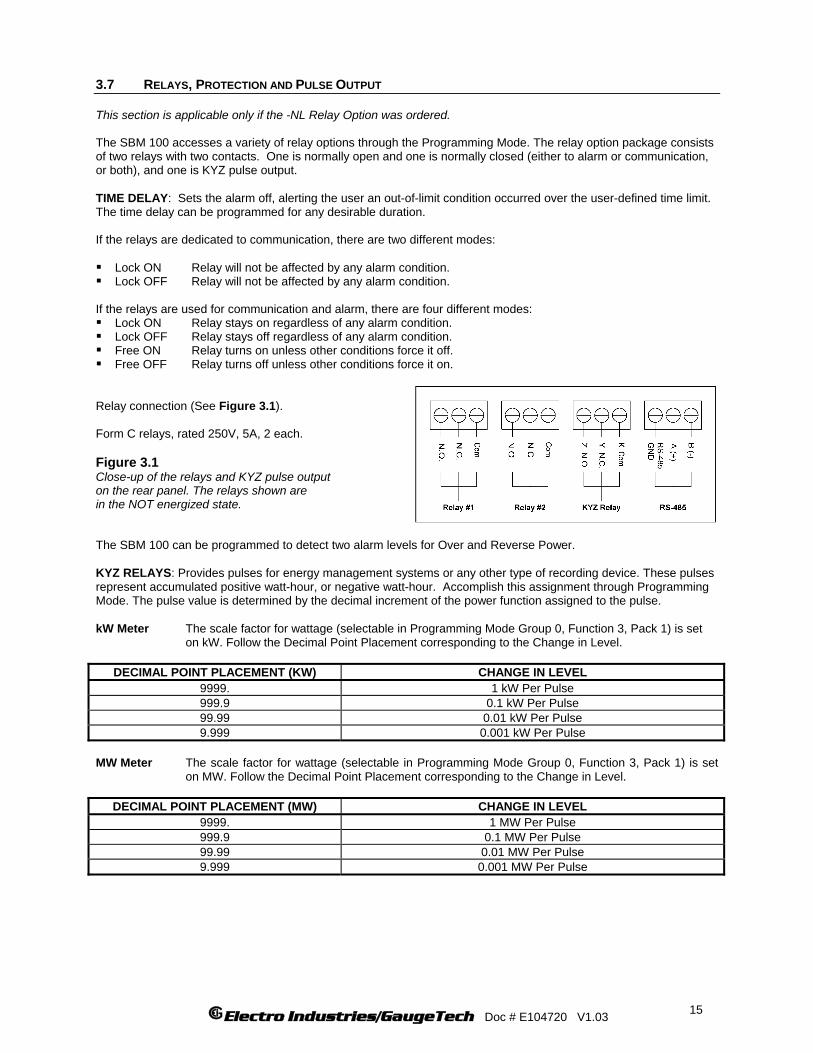
3.7 RELAYS, PROTECTION AND PULSE OUTPUT This section is applicable only if the -NL Relay Option was ordered. The SBM 100 accesses a variety of relay options through the Programming Mode. The relay option package consists of two relays with two contacts. One is normally open and one is normally closed (either to alarm or communication, or both), and one is KYZ pulse output. TIME DELAY: Sets the alarm off, alerting the user an out-of-limit condition occurred over the user-defined time limit. The time delay can be programmed for any desirable duration. If the relays are dedicated to communication, there are two different modes: Lock ON Relay will not be affected by any alarm condition. Lock OFF Relay will not be affected by any alarm condition.
If the relays are used for communication and alarm, there are four different modes: Lock ON Relay stays on regardless of any alarm condition. Lock OFF Relay stays off regardless of any alarm condition. Free ON Relay turns on unless other conditions force it off. Free OFF Relay turns off unless other conditions force it on.
Relay connection (See Figure 3.1). Form C relays, rated 250V, 5A, 2 each. Figure 3.1 Close-up of the relays and KYZ pulse output on the rear panel. The relays shown are in the NOT energized state.
The SBM 100 can be programmed to detect two alarm levels for Over and Reverse Power. KYZ RELAYS: Provides pulses for energy management systems or any other type of recording device. These pulses represent accumulated positive watt-hour, or negative watt-hour. Accomplish this assignment through Programming Mode. The pulse value is determined by the decimal increment of the power function assigned to the pulse. kW Meter The scale factor for wattage (selectable in Programming Mode Group 0, Function 3, Pack 1) is set
on kW. Follow the Decimal Point Placement corresponding to the Change in Level.
DECIMAL POINT PLACEMENT (KW) CHANGE IN LEVEL 9999. 1 kW Per Pulse 999.9 0.1 kW Per Pulse 99.99 0.01 kW Per Pulse 9.999 0.001 kW Per Pulse
MW Meter The scale factor for wattage (selectable in Programming Mode Group 0, Function 3, Pack 1) is set
on MW. Follow the Decimal Point Placement corresponding to the Change in Level.
DECIMAL POINT PLACEMENT (MW) CHANGE IN LEVEL 9999. 1 MW Per Pulse 999.9 0.1 MW Per Pulse 99.99 0.01 MW Per Pulse 9.999 0.001 MW Per Pulse

Electro Industries/GaugeTech Doc # E104720 V1.03
16
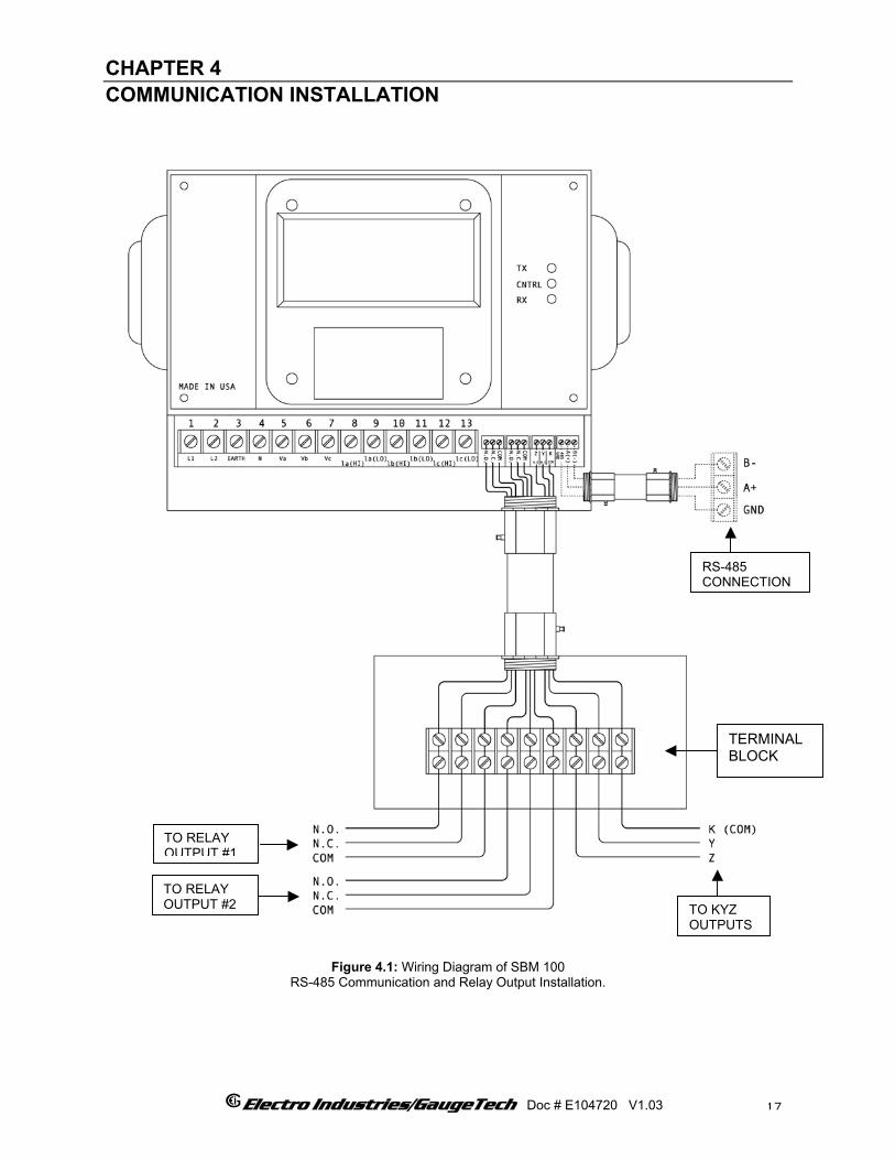
CHAPTER 4
COMMUNICATION INSTALLATION
TERMINAL BLOCK
TO RELAY OUTPUT #1
Figure 4.1: Wiring Diagram of SBM 100 RS-485 Communication and Relay Output Installation.
Electro Industries/GaugeTech Doc # E104720 V1.03
TO KYZ OUTPUTS
RS-485 CONNECTION
TO RELAY OUTPUT #2
17
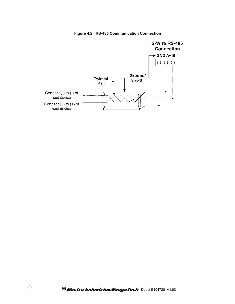
Figure 4.2 RS-485 Communication Connection
Electro Industries/GaugeTech Doc # E104720 V1.03
18

4.1 RS-485 Each SBM 100 instrument has an unique address up to four digits. Available standard baud rates are available up to 4800 baud. To select the proper baud rate, apply the following rules: For a smaller number of instruments over a long distance, use a lower baud rate. Optimal recommended baud rate is 1200 baud. RS-485 parallels multiple instruments on the same link. Its operating capability is up to 4000 feet. When using only 2 wires (on the RS-485), the link can include up to 30 instruments (see Figure 4.2 above). 4.2 NETWORK OF INSTRUMENTS AND LONG DISTANCE COMMUNICATION Use modems (dedicated or dial-up) when the instruments are located at great distances. However, set the modem to auto answer at the recommended value of 1200 baud rate, if noise conditions exist. Also, flow control must be disabled.
I. MODEM CONNECTED TO COMPUTER (ORIGINATE MODEM)
PROGRAMMING THE MODEM Comply with the modem’s instruction manual and follow these instructions: RESTORE MODEM TO FACTORY SETTINGS: • Erases all previously programmed settings. SET MODEM TO DISPLAY RESULT CODES: • The device uses the result codes. SET MODEM TO VERBAL RESULT CODE: • The device uses the verbal codes. SET MODEM TO IGNORE DTR SIGNAL: • Necessary for the device to ensure connection with originate modem. SET MODEM TO DISABLE FLOW CONTROL: • Necessary to communicate with remote modem connected to device. TELL MODEM TO WRITE THE NEW SETTINGS TO ACTIVATE PROFILE: • Places these settings into nonvolatile memory; the settings take effect after the modem powers up.
Electro Industries/GaugeTech Doc # E104720 V1.03
19

II. MODEM CONNECTED TO THE DEVICE (REMOTE MODEM)
PROGRAMMING THE MODEM Comply with the modem’s instruction manual and follow these instructions: RESTORE MODEM TO FACTORY SETTINGS: • Erases all previously programmed settings. SET MODEM TO AUTO ANSWER ON N RINGS: • Sets the remote modem to answer the call after N rings. SET THE MODEM TO AUTO NEGOTIATE MODE: • Sets the remote to auto-negotiate to communicate successfully with the Futura+ Series and other devices in the
modem. SET MODEM TO RETURN NUMERIC RESULT CODES: • Increases speed connection with the Futura+ Series. SET MODEM TO IGNORE DTR SIGNAL: • Necessary for device to ensure connection with originate modem. SET MODEM TO DISABLE FLOW CONTROL: • Necessary to communicate with remote modem connected to the Futura+ Series TELL THE MODEM TO WRITE THE NEW SETTINGS TO ACTIVATE PROFILE: Places new settings into nonvolatile memory; settings take effect after the modem powers up.
Electro Industries/GaugeTech Doc # E104720 V1.03
20

CHAPTER 5 SBM 100 OVERVIEW The SBM 100 monitors Kilowatt, Kilowatt Demand and Kilowatt-Hour readings.
MODE
pe.
ADV SET
LM1 LM2
KWHKWKWD
A C KILOWATTS
TX
CNTRL
RX
Figure 5.1 The SBM 100 front panel with display and keypad.
A glowing Annunciator indicates the Power Function currently displayed
5.1 THE SBM 100 METER SYSTEM The SBM 100 measures electrical power demand and energy for usage monitoring, cost allocation, load monitoring or demand tracking and control. The digital display is intuitive and requires virtually no user training. Open Modbus digital communication protocol ensures simple interface to any digital control or monitoring system. The SBM 100 is a basic energy/demand meter. 5.2 PRODUCT FEATURES
• True RMS measurements of bi-directional energy, power and demand. • Tracks positive and negative kWh in separate registers. • ANSI C-12 revenue metering accuracy. • Reads primary values; no multiplication factors are required. • User programmable for any PT and CT ratio. • KYZ pulse output. • Relay output for over/under power alarms. • Six digit, long-life LED display. • Super Bright display for outdoor application. • Supports Modbus RTU digital protocol. • Supports RS-485 communication connection. • Surface mount design for easy installation. • Meets and exceeds IEEE C37.90.1 surge withstand requirements to ensure long life, even in harsh electrical
environments. • Designed for harsh temperature conditions ( - 20 to + 70) ° C. • Dimensions – 8.375”W x 7.125”H x 4.25”D.
Electro Industries/GaugeTech Doc # E104720 V1.03
21
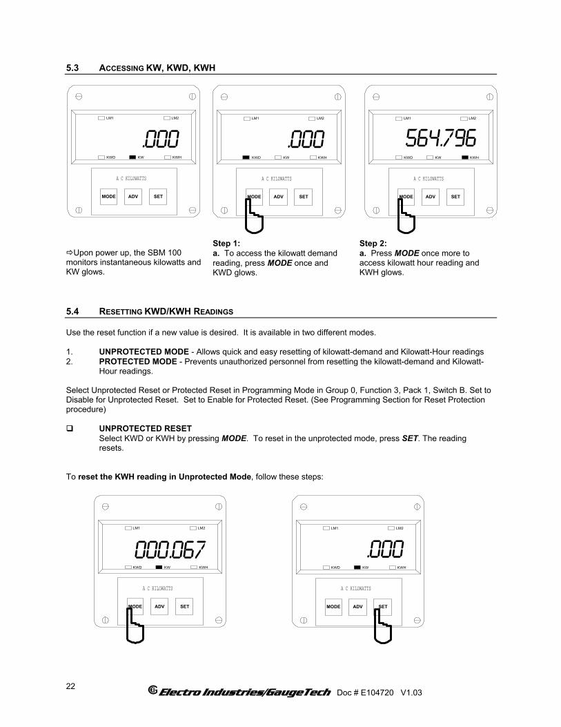
5.3 ACCESSING KW, KWD, KWH
MODE
.000
ADV SET
LM1 LM2
KWHKWKWD
A C KILOWATTS
MODE
.000
ADV SET
LM1 LM2
KWHKWKWD
A C KILOWATTS
MODE
564.796
ADV SET
LM1 LM2
KWHKWKWD
A C KILOWATTS
Upon power up, the SBM 100
monitors instantaneous kilowatts and KW glows.
Step 1: a. To access the kilowatt demand reading, press MODE once and KWD glows.
Step 2: a. Press MODE once more to access kilowatt hour reading and KWH glows.
5.4 RESETTING KWD/KWH READINGS Use the reset function if a new value is desired. It is available in two different modes. 1. UNPROTECTED MODE - Allows quick and easy resetting of kilowatt-demand and Kilowatt-Hour readings 2. PROTECTED MODE - Prevents unauthorized personnel from resetting the kilowatt-demand and Kilowatt- Hour readings. Select Unprotected Reset or Protected Reset in Programming Mode in Group 0, Function 3, Pack 1, Switch B. Set to Disable for Unprotected Reset. Set to Enable for Protected Reset. (See Programming Section for Reset Protection procedure)
UNPROTECTED RESET Select KWD or KWH by pressing MODE. To reset in the unprotected mode, press SET. The reading resets. To reset the KWH reading in Unprotected Mode, follow these steps:
MODE
000.067
ADV SET
LM1 LM2
KWHKWKWD
A C KILOWATTS
MODE
.000
ADV SET
LM1 LM2
KWHKWKWD
A C KILOWATTS
Electro Industries/GaugeTech Doc # E104720 V1.03
22
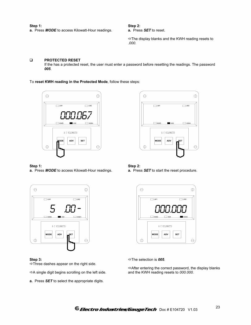
Step 1: a. Press MODE to access Kilowatt-Hour readings.
Step 2: a. Press SET to reset.
The display blanks and the KWH reading resets to .000.
PROTECTED RESET If the has a protected reset, the user must enter a password before resetting the readings. The password 005. To reset KWH reading in the Protected Mode, follow these steps:
MODE
000.067
ADV SET
LM1 LM2
KWHKWKWD
A C KILOWATTS
MODE ADV SET
LM1 LM2
KWHKWKWD
A C KILOWATTS
Step 1: a. Press MODE to access Kilowatt-Hour readings.
Step 2: a. Press SET to start the reset procedure.
MODE
000.000
ADV SET
LM1 LM2
KWHKWKWD
A C KILOWATTS
MODE
5 .00
ADV SET
LM1 LM2
KWHKWKWD
A C KILOWATTS
_
Step 3:
Three dashes appear on the right side.
A single digit begins scrolling on the left side. a. Press SET to select the appropriate digits.
The selection is 005.
After entering the correct password, the display blanks and the KWH reading resets to 000.000.
Electro Industries/GaugeTech Doc # E104720 V1.03
23
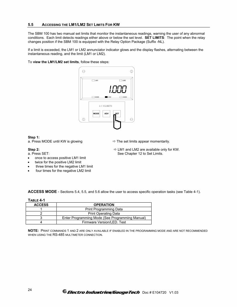
5.5 ACCESSING THE LM1/LM2 SET LIMITS FOR KW The SBM 100 has two manual set limits that monitor the instantaneous readings, warning the user of any abnormal conditions. Each limit detects readings either above or below the set level. SET LIMITS: The point when the relay changes position if the SBM 100 is equipped with the Relay Option Package (Suffix -NL). If a limit is exceeded, the LM1 or LM2 annunciator indicator glows and the display flashes, alternating between the instantaneous reading, and the limit (LM1 or LM2). To view the LM1/LM2 set limits, follow these steps:
MODE
I.000
ADV SET
LM1 LM2
KWHKWKWD
A C KILOWATTS
Step 1: a. Press MODE until KW is glowing The set limits appear momentarily. Step 2: LM1 and LM2 are available only for KW. a. Press SET: See Chapter 12 to Set Limits. • once to access positive LM1 limit • twice for the positive LM2 limit • three times for the negative LM1 limit • four times for the negative LM2 limit ACCESS MODE - Sections 5.4, 5.5, and 5.6 allow the user to access specific operation tasks (see Table 4-1). TABLE 4-1
ACCESS OPERATION 1 Print Programming Data 2 Print Operating Data 3 Enter Programming Mode (See Programming Manual) 4 Firmware Version/LED. Test
NOTE: PRINT COMMANDS 1 AND 2 ARE ONLY AVAILABLE IF ENABLED IN THE PROGRAMMING MODE AND ARE NOT RECOMMENDED WHEN USING THE RS-485 MULTIMETER CONNECTION.
Electro Industries/GaugeTech Doc # E104720 V1.03
24
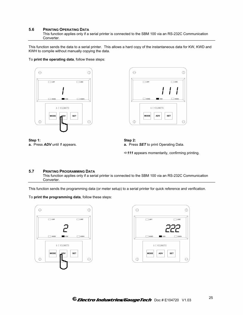
5.6 PRINTING OPERATING DATA This function applies only if a serial printer is connected to the SBM 100 via an RS-232C Communication Converter. This function sends the data to a serial printer. This allows a hard copy of the instantaneous data for KW, KWD and KWH to compile without manually copying the data. To print the operating data, follow these steps:
MODE
I I I
ADV SET
LM1 LM2
KWHKWKWD
A C KILOWATTS
MODE
I
ADV SET
LM1 LM2
KWHKWKWD
A C KILOWATTS
Step 1: a. Press ADV until 1 appears.
Step 2: a. Press SET to print Operating Data.
111 appears momentarily, confirming printing. 5.7 PRINTING PROGRAMMING DATA This function applies only if a serial printer is connected to the SBM 100 via an RS-232C Communication Converter. This function sends the programming data (or meter setup) to a serial printer for quick reference and verification. To print the programming data, follow these steps:
MODE
2
ADV SET
LM1 LM2
KWHKWKWD
A C KILOWATTS
MODE
222
ADV SET
LM1 LM2
KWHKWKWD
A C KILOWATTS
Electro Industries/GaugeTech Doc # E104720 V1.03
25
Step 1: a. Press ADV until 2 appears.
Step 2: a. Press SET to print the Programming data.
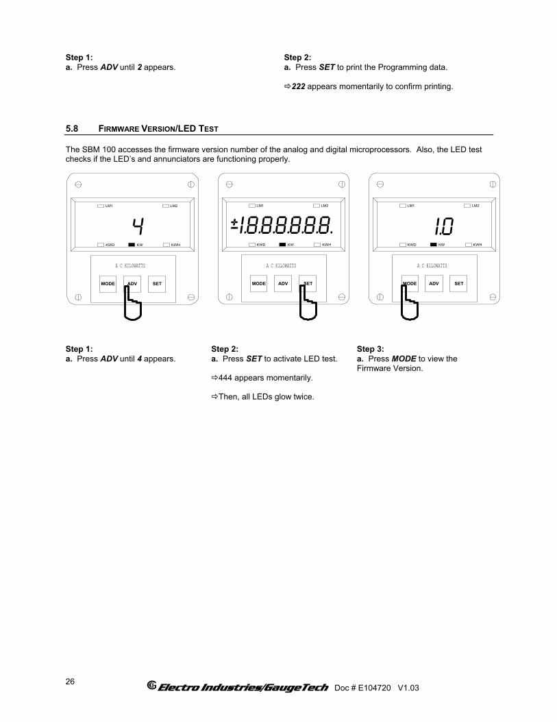
222 appears momentarily to confirm printing. 5.8 FIRMWARE VERSION/LED TEST The SBM 100 accesses the firmware version number of the analog and digital microprocessors. Also, the LED test checks if the LED’s and annunciators are functioning properly.
MODE
I.8.8.8.8.8.8.
ADV SET
LM1 LM2
KWHKWKWD
A C KILOWATTS
+_
MODE
I.0
ADV SET
LM1 LM2
KWHKWKWD
A C KILOWATTS
MODE
4
ADV SET
LM1 LM2
KWHKWKWD
A C KILOWATTS
Step 1: a. Press ADV until 4 appears.
Step 2: a. Press SET to activate LED test.
444 appears momentarily.
Then, all LEDs glow twice.
Step 3: a. Press MODE to view the Firmware Version.
Electro Industries/GaugeTech Doc # E104720 V1.03
26

CHAPTER 6 PROGRAMMING OVERVIEW 6.1 HOW TO USE THIS PORTION OF THE MANUAL This manual contains programming for the basic operation, available options and parameters. Using the table of contents, find the programming feature location and read that chapter. Programming tasks are arranged into seven GROUPS. Within each GROUP are the specific meter FUNCTIONS. Outlined is the general approach to alter programming mode values. 1. Enter the Programming Mode. 2. Select the desired GROUP. 3. Once the desired GROUP is selected, select a FUNCTION within the GROUP. 4. After the FUNCTION selection, proceed with DATA ENTRY of the new value of the desired parameter. 5. Proceed to program another location and/or exit the programming mode. IMPORTANT: The full exiting procedure must be followed to store any new programming. 6.2 SWITCH PACKS
PACK
AC KILOWATTSMODE ADV SET
KWHKWD KW
TOGGLE SWITCHES:'A' THRU 'D' FROM
LEFT TO RIGHT
FUNCTION
GROUPS, Functions, and Switch PACKS • GROUPS are the main category. • Functions are sub categories of GROUPS. • Switch PACKS are sub categories of
FUNCTIONS.
The diagram below illustrates the arrangement of the three
categories: GROUPS Functions Switch PACKS
Electro Industries/GaugeTech Doc # E104720 V1.03
27
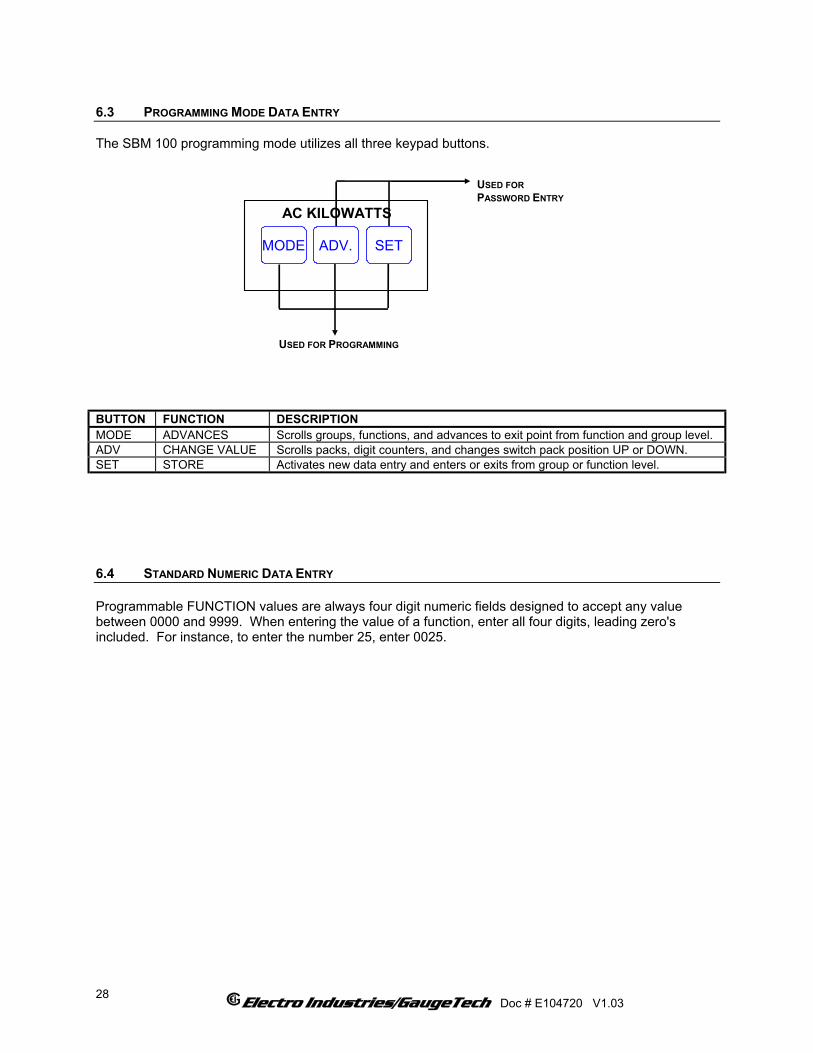
6.3 PROGRAMMING MODE DATA ENTRY The SBM 100 programming mode utilizes all three keypad buttons.
USED FORPASSWORD ENTRY
USED FOR PROGRAMMING
AC KILOWATTS
ADV.MODE SET
BUTTON FUNCTION DESCRIPTION MODE ADVANCES Scrolls groups, functions, and advances to exit point from function and group level. ADV CHANGE VALUE Scrolls packs, digit counters, and changes switch pack position UP or DOWN. SET STORE Activates new data entry and enters or exits from group or function level. 6.4 STANDARD NUMERIC DATA ENTRY Programmable FUNCTION values are always four digit numeric fields designed to accept any value between 0000 and 9999. When entering the value of a function, enter all four digits, leading zero's included. For instance, to enter the number 25, enter 0025.
Electro Industries/GaugeTech Doc # E104720 V1.03
28

CHAPTER 7 ENTERING THE PROGRAMMING MODE 7.1 PASSWORD ENTRY NOTE: TO ENTER THE PROGRAMMING MODE THE SBM 100 MUST BE IN THE KW MODE. The SBM 100 is password protected. To enter the Programming Mode, key in the following password. The password is 555. The password entry may seem awkward at first. It is designed initially be difficult to use. This secures unauthorized tampering. After the user becomes familiar with password entry, it will be quick and easy to enter. NOTE: THE METER WILL NOT STORE ANY PROGRAMMING UNLESS PROPERLY EXITED. (SEE CHAPTER 13 TO EXIT).
ENTERING THE PROGRAMMING MODE:
MODE
3
ADV SET
LM1 LM2
KWHKWKWD
A C KILOWATTS
MODE
5 555
ADV SET
LM1 LM2
KWHKWKWD
A C KILOWATTS
MODE
p0.
ADV SET
LM1 LM2
KWHKWKWD
A C KILOWATTS
Step 1: a. Press ADV. until 3 appears. b. Press SET to select and 333 flashes momentarily.
Step 2: Three dashes appear to the right
and digits begin scrolling to the left.
The password is 555. a. Press SET each time 5 appears.
Selected digits appear.
Display blanks and PPP flashes,
confirming a correctly entered password.
PPP is replaced by P0. and the meter is now in the Programming Mode, GROUP 0.
Electro Industries/GaugeTech Doc # E104720 V1.03 29

Electro Industries/GaugeTech Doc # E104720 V1.03
30
CHAPTER 8 PROGRAMMING GROUP 0: GLOBAL METER SETUP The Global Meter Setup includes functions 0 through 5 that control configuration and basic operation. TABLE 8-1: GROUP 0 PROGRAMMING FORMAT
FUNCTION NUMBER FUNCTION 0. Interval 1. Meter Address for Communication 2. Baud Rate for Communication 3. System Configuration 4. Delay Time in Seconds for Relay 1 5. Delay Time in Seconds for Relay 2 E. Exit Programming Group 0
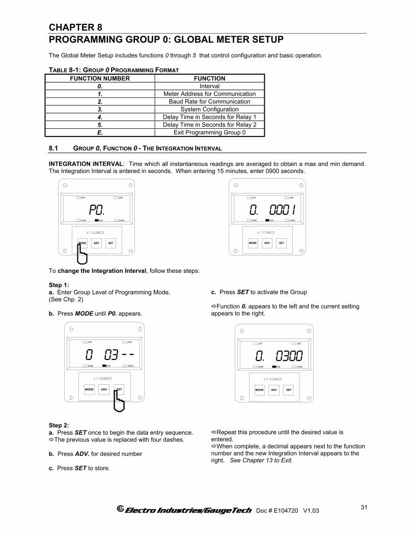
8.1 GROUP 0, FUNCTION 0 - THE INTEGRATION INTERVAL INTEGRATION INTERVAL: Time which all instantaneous readings are averaged to obtain a max and min demand. The Integration Interval is entered in seconds. When entering 15 minutes, enter 0900 seconds.
MODE
0. 000 I
ADV SET
LM1 LM2
KWHKWKWD
A C KILOWATTS
MODE
P0.
ADV SET
LM1 LM2
KWHKWKWD
A C KILOWATTS
To change the Integration Interval, follow these steps: Step 1: a. Enter Group Level of Programming Mode, (See Chp. 2) b. Press MODE until P0. appears.
c. Press SET to activate the Group
Function 0. appears to the left and the current setting appears to the right.
Step 2: a. Press SET once to begin the data entry sequence.
The previous value is replaced with four dashes. b. Press ADV. for desired number c. Press SET to store.
Repeat this procedure until the desired value is
entered. When complete, a decimal appears next to the function
number and the new Integration Interval appears to the right. See Chapter 13 to Exit.
MODE
0 03
ADV SET
LM1 LM2
KWHKWKWD
A C KILOWATTS
__
MODE
0. 0300
ADV SET
LM1 LM2
KWHKWKWD
A C KILOWATTS
Electro Industries/GaugeTech Doc # E104720 V1.03
31

8.2 GROUP 0, FUNCTION 1 - THE METER ADDRESS METER ADDRESS: Identifies the meter when communicating with digital communications. When numerous meters at one site, it is essential that each meter have its own address. To change the Meter Address, follow these steps:
MODE
I. 0020
ADV SET
LM1 LM2
KWHKWKWD
A C KILOWATTS
MODE
p0.
ADV SET
LM1 LM2
KWHKWKWD
A C KILOWATTS
Step 1: a. Enter Group Level of Programming Mode, (See Chp. 2). b. Press MODE until P0. appears. c. Press SET to activate the Group.
Step 2: a. Press MODE until Function 1. appears.
The current meter address appears to the right of the function number.
MODE
I 03
ADV SET
LM1 LM2
KWHKWKWD
A C KILOWATTS
__
MODE
I. 0300
ADV SET
LM1 LM2
KWHKWKWD
A C KILOWATTS
Step 3: a. Press SET once to begin Data Entry Sequence.
The previous value is replaced by four dashes. b. Press ADV. until the desired number appears. c. Press SET to store.
Repeat this procedure until new Address is entered.
Once complete, a decimal appears next to the function
number and the new Address appears to the right. See Chapter 13 to Exit.
8.3 GROUP 0, FUNCTION 2 - THE COMMUNICATION BAUD RATE BAUD RATE: Speed at which data is transmitted between meter and remote computer or serial printer. The rate programmed into the meter must match the rate used by the remote device. Valid Baud Rates are 110, 150, 300, 600, 1200, 2400, 4800 and 9600.
Electro Industries/GaugeTech Doc # E104720 V1.03
32
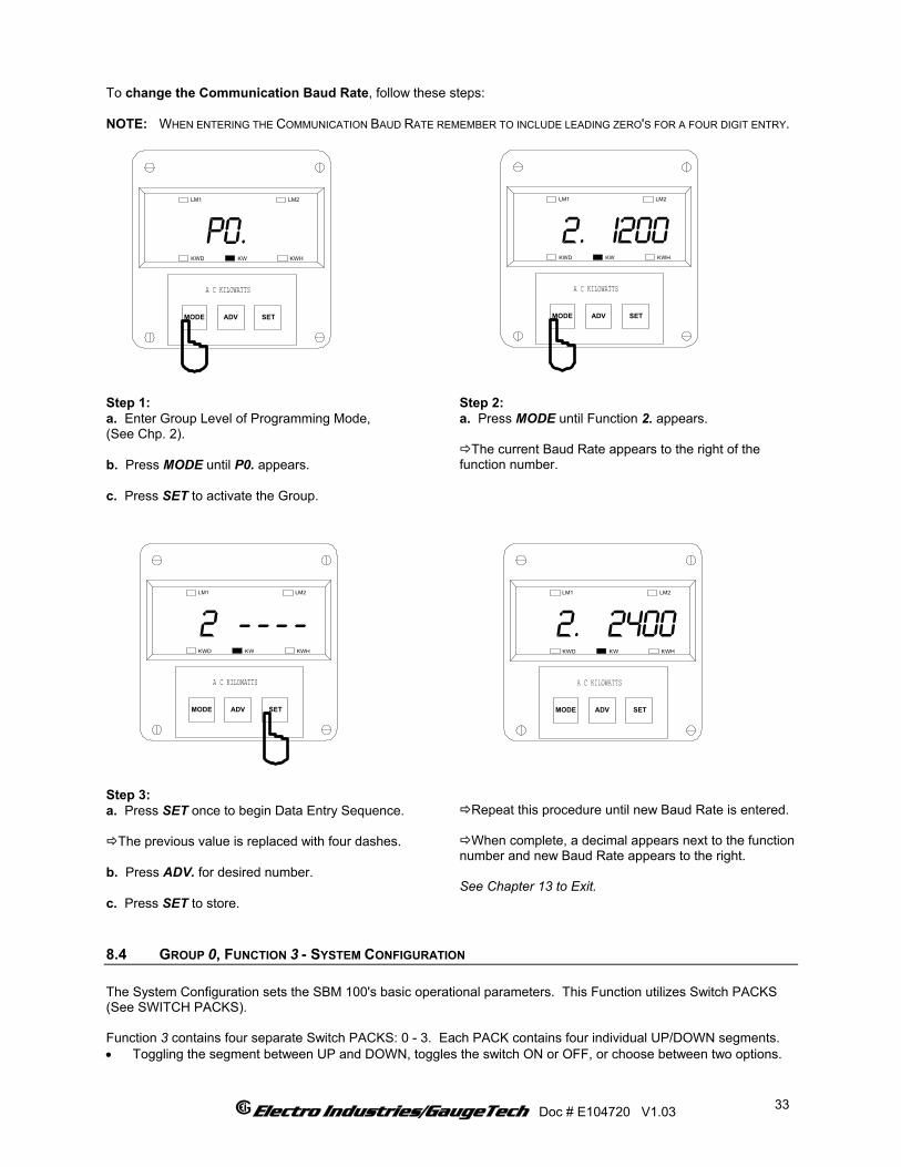
To change the Communication Baud Rate, follow these steps: NOTE: WHEN ENTERING THE COMMUNICATION BAUD RATE REMEMBER TO INCLUDE LEADING ZERO'S FOR A FOUR DIGIT ENTRY.
MODE
2. I200
ADV SET
LM1 LM2
KWHKWKWD
A C KILOWATTS
MODE
p0.
ADV SET
LM1 LM2
KWHKWKWD
A C KILOWATTS
Step 1: a. Enter Group Level of Programming Mode, (See Chp. 2). b. Press MODE until P0. appears. c. Press SET to activate the Group.
Step 2: a. Press MODE until Function 2. appears.
The current Baud Rate appears to the right of the function number.
Step 3: a. Press SET once to begin Data Entry Sequence.
The previous value is replaced with four dashes. b. Press ADV. for desired number. c. Press SET to store.
Repeat this procedure until new Baud Rate is entered.
When complete, a decimal appears next to the function
number and new Baud Rate appears to the right. See Chapter 13 to Exit.
MODE
2
ADV SET
LM1 LM2
KWHKWKWD
A C KILOWATTS
_ _ _ _
MODE
2. 2400
ADV SET
LM1 LM2
KWHKWKWD
A C KILOWATTS
8.4 GROUP 0, FUNCTION 3 - SYSTEM CONFIGURATION The System Configuration sets the SBM 100's basic operational parameters. This Function utilizes Switch PACKS (See SWITCH PACKS). Function 3 contains four separate Switch PACKS: 0 - 3. Each PACK contains four individual UP/DOWN segments. • Toggling the segment between UP and DOWN, toggles the switch ON or OFF, or choose between two options.
Electro Industries/GaugeTech Doc # E104720 V1.03
33
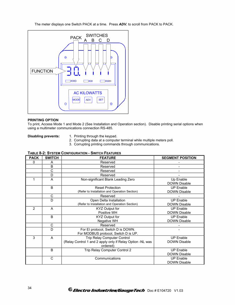
The meter displays one Switch PACK at a time. Press ADV. to scroll from PACK to PACK.
A B C DPACK
AC KILOWATTSMODE ADV SET
KWHKWD KW
SWITCHES
FUNCTION
PRINTING OPTION To print, Access Mode 1 and Mode 2 (See Installation and Operation section). Disable printing serial options when using a multimeter communications connection RS-485. Disabling prevents: 1. Printing through the keypad. 2. Corrupting data at a computer terminal while multiple meters poll. 3. Corrupting printing commands through communications. TABLE 8-2: SYSTEM CONFIGURATION - SWITCH FEATURES PACK SWITCH FEATURE SEGMENT POSITION
0 A Reserved - B Reserved - C Reserved - D Reserved -
1 A Non-significant Blank Leading Zero Up Enable DOWN Disable
B Reset Protection (Refer to Installation and Operation Section)
UP Enable DOWN Disable
C Reserved - D Open Delta Installation
(Refer to Installation and Operation Section) UP Enable
DOWN Disable 2 A KYZ Output for
Positive WH UP Enable
DOWN Disable B KYZ Output for
Negative WH UP Enable
DOWN Disable C Reserved - D For EI protocol, Switch D is DOWN.
For MODBUS protocol, Switch D is UP. -
3 A Trip Relay Computer Control (Relay Control 1 and 2 apply only if Relay Option -NL was
ordered)
UP Enable DOWN Disable
B Trip Relay Computer Control 2 UP Enable DOWN Disable
C Communications UP Enable DOWN Disable
Electro Industries/GaugeTech Doc # E104720 V1.03
34
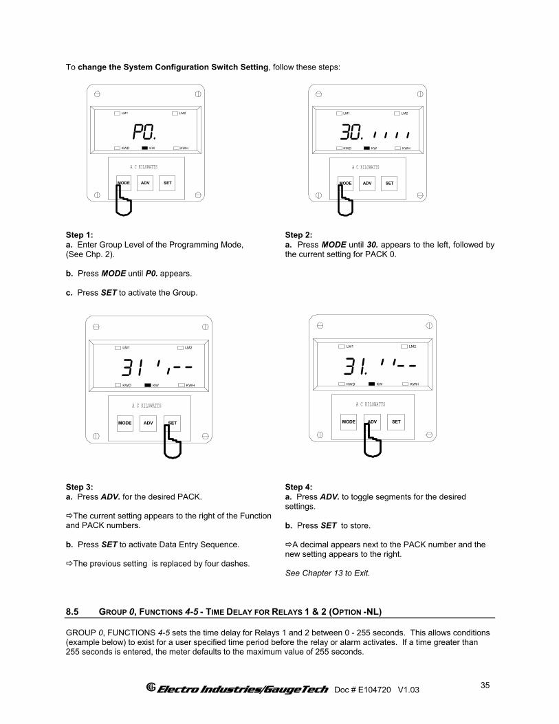
To change the System Configuration Switch Setting, follow these steps:
MODE
p0.
ADV SET
LM1 LM2
KWHKWKWD
A C KILOWATTS
MODE
30.
ADV SET
LM1 LM2
KWHKWKWD
A C KILOWATTS
_ _ _ _
Step 1: a. Enter Group Level of the Programming Mode, (See Chp. 2). b. Press MODE until P0. appears. c. Press SET to activate the Group.
Step 2: a. Press MODE until 30. appears to the left, followed by the current setting for PACK 0.
MODE
3 I.
ADV SET
LM1 LM2
KWHKWKWD
A C KILOWATTS
_ _ _ _
MODE
3 I
ADV SET
LM1 LM2
KWHKWKWD
A C KILOWATTS
_ _ _ _
Step 3: a. Press ADV. for the desired PACK.
The current setting appears to the right of the Function and PACK numbers. b. Press SET to activate Data Entry Sequence.
The previous setting is replaced by four dashes.
Step 4: a. Press ADV. to toggle segments for the desired settings. b. Press SET to store.
A decimal appears next to the PACK number and the new setting appears to the right. See Chapter 13 to Exit.
8.5 GROUP 0, FUNCTIONS 4-5 - TIME DELAY FOR RELAYS 1 & 2 (OPTION -NL) GROUP 0, FUNCTIONS 4-5 sets the time delay for Relays 1 and 2 between 0 - 255 seconds. This allows conditions (example below) to exist for a user specified time period before the relay or alarm activates. If a time greater than 255 seconds is entered, the meter defaults to the maximum value of 255 seconds.
Electro Industries/GaugeTech Doc # E104720 V1.03
35
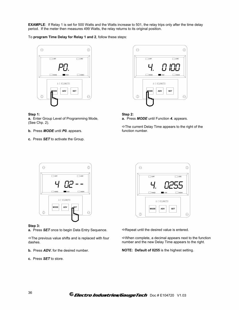
EXAMPLE: If Relay 1 is set for 500 Watts and the Watts increase to 501, the relay trips only after the time delay period. If the meter then measures 499 Watts, the relay returns to its original position. To program Time Delay for Relay 1 and 2, follow these steps:
MODE
p0.
ADV SET
LM1 LM2
KWHKWKWD
A C KILOWATTS
MODE
4. 0 I00
ADV SET
LM1 LM2
KWHKWKWD
A C KILOWATTS
Step 1: a. Enter Group Level of Programming Mode, (See Chp. 2). b. Press MODE until P0. appears. c. Press SET to activate the Group.
Step 2: a. Press MODE until Function 4. appears.
The current Delay Time appears to the right of the function number.
Step 3: a. Press SET once to begin Data Entry Sequence.
The previous value shifts and is replaced with four dashes. b. Press ADV. for the desired number. c. Press SET to store.
Repeat until the desired value is entered.
When complete, a decimal appears next to the function
number and the new Delay Time appears to the right. NOTE: Default of 0255 is the highest setting.
MODE
4 02
ADV SET
LM1 LM2
KWHKWKWD
A C KILOWATTS
_ _
MODE
4. 0255
ADV SET
LM1 LM2
KWHKWKWD
A C KILOWATTS
Electro Industries/GaugeTech Doc # E104720 V1.03
36
CHAPTER 9 PROGRAMMING GROUP 1: FULL SCALE SETTINGS FOR WATTS Programming Group 1 provides Full Scale Settings for Watts. The site technician has a choice of Scale Selection between Kilowatts and Megawatts. TABLE 9-1: GROUP 1 PROGRAMMING FORMAT
FUNCTION NUMBER FUNCTION 0. Full Scale Selection for Watts E. Exit Programming Group 1
9.1 GROUP 1, FUNCTION 0 - FULL SCALE SETTINGS AND DECIMAL POINT PLACEMENT FOR WATTS Programming Group 1, Function 0 provides decimal point positioning for maximum resolution. EXAMPLE 1: Full Scale Voltage (FSV) = 120 V Full Scale Amperage (FSA) = 5.00 A Full Scale Wattage (FSW) is the product of FSV and FSA. For the FSW for two and a half or three element multiply the FSW by 3. For two element multiply the FSW by 2. FSW (one element) = 120 V • 5.00 A FSW (one element) = 600 W FSW (three element) = 600 W •3 = 1,800 W Here the FSW is too small a value for a Megawatt meter. FSW in the Kilowatt meter equals 1.800 KW. In Function 2, place the decimal point after the first digit from the left. EXAMPLE 2: 480/120, 1000/5 CT FSV = 480 V FSA = 1000 A FSW (one element) = 480 V • 1000 A FSW (one element) = 480,000 W FSW (three element) = 480,000 W • 3 = 1,440,000 W FSW for Kilowatt a meter equals 1440. KW. FSW for a Megawatt meter equals 1.440 MW. In Function 2 place the decimal point after the last digit for a Kilowatt meter and after the first digit for a Megawatt meter. EXAMPLE 3: FSV = 1.440 KV FSA = 1000 A FSW (one element) = 1440 V • 1000 A FSW (one element) = 1,440,000 W FSW (three element) = 1,440, 000 W • 3 = 4,320,000 W FSW for a Kilowatt meter equals 4320 KW. Here the FSW is too large a value for a Kilowatt meter (the range is 0 - 1000). FSW for a Megawatt meter equals 04.32 MW. In Function 2, place the decimal point after the second digit. EXAMPLE 4: 277/480 DELTA, NO PT FSV = 300 V FSA = 1000 A FSW (one element) = 300 V • 1000 A FSW (one element) = 300,000 W FSW (three element) = 300, 000 W • 3 = 900,000 W (or 900 KW) FSW enter 0900 KW.
Electro Industries/GaugeTech Doc # E104720 V1.03
37

To change the Full Scale Setting and Decimal Point Placement for Watts, follow these steps:
MODE
0.
ADV SET
LM1 LM2
KWHKWKWD
A C KILOWATTS_
04.32
MODE
p I.
ADV SET
LM1 LM2
KWHKWKWD
A C KILOWATTS
Step 1: a. Enter Group Level of the Programming Mode, (See Chp. 2). b. Press MODE until P1. appears. c. Press SET to activate the Group.
Step 2: 0. appears to the left, followed by the current Scale
Factor, Full Scale, and Decimal Point Placement Settings.
ENTERING THE SCALE FACTOR Step 3: a. Press SET to begin Data Entry.
The current setting is replaced by a single dash to the far right.
The Function Number remains on the far left. b. Press ADV. to toggle. UP - Megawatts DOWN - Kilowatts c. Press SET to store.
DECIMAL POINT SELECTION Step 4: a. Press ADV. to move the decimal point to desired position. b. Press SET to store.
MODE
0
ADV SET
LM1 LM2
KWHKWKWD
A C KILOWATTS
_
MODE
0 .
ADV SET
LM1 LM2
KWHKWKWD
A C KILOWATTS
Electro Industries/GaugeTech Doc # E104720 V1.03
38
MODE
0 0
ADV SET
LM1 LM2
KWHKWKWD
A C KILOWATTS
___.
MODE
0.
ADV SET
LM1 LM2
KWHKWKWD
A C KILOWATTS
_ I.800
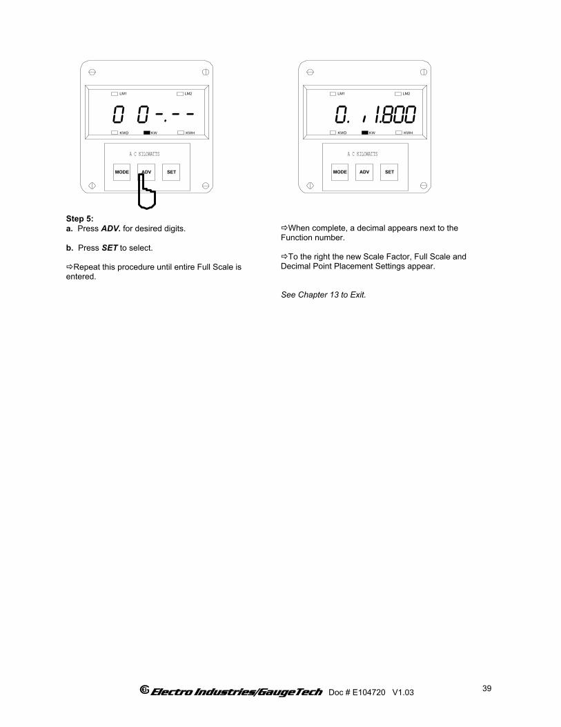
Step 5: a. Press ADV. for desired digits. b. Press SET to select.
Repeat this procedure until entire Full Scale is entered.
When complete, a decimal appears next to the
Function number.
To the right the new Scale Factor, Full Scale and Decimal Point Placement Settings appear. See Chapter 13 to Exit.
Electro Industries/GaugeTech Doc # E104720 V1.03
39

Electro Industries/GaugeTech Doc # E104720 V1.03
40
CHAPTER 10 PROGRAMMING GROUP 2: METER CALIBRATION
WARNING - READ THIS SECTION CAREFULLY BEFORE PROCEEDING:
⌦ The calibration procedure requires highly accurate and stable input signals. Incorrect readings result from
improper calibration procedures. If unsure, return unit to the factory for calibration. ⌦ BEFORE calibrating any channel, make a note of its Full Scale Setting (See Chapter 9). Set the Full Scale in
accordance with Table 10-2 for calibration. Restore original Full Scale Setting when calibration is completed. ⌦ The first function in Group 2 (STD.CORR) is NOT to be changed by the user. Please make a note of the value
here ( ) before using any other function in this group. If the STD.CORR value is inadvertently lost or changed, contact the factory for assistance.
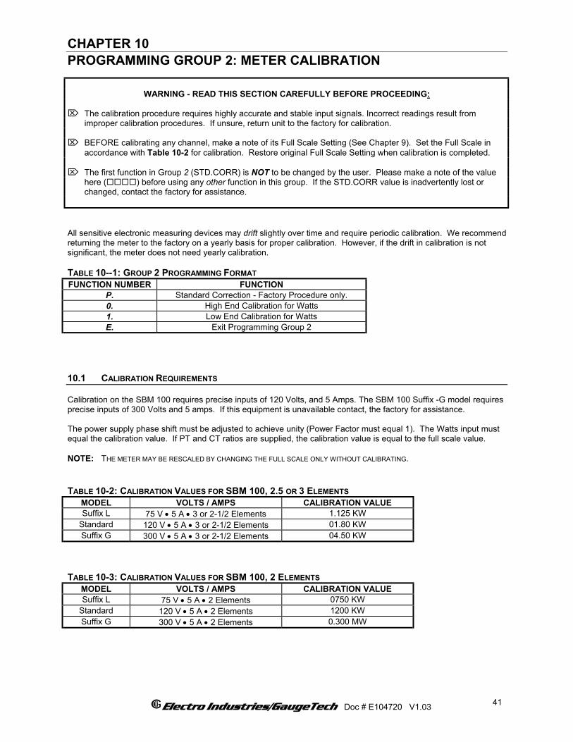
All sensitive electronic measuring devices may drift slightly over time and require periodic calibration. We recommend returning the meter to the factory on a yearly basis for proper calibration. However, if the drift in calibration is not significant, the meter does not need yearly calibration. TABLE 10--1: GROUP 2 PROGRAMMING FORMAT FUNCTION NUMBER FUNCTION
P. Standard Correction - Factory Procedure only. 0. High End Calibration for Watts 1. Low End Calibration for Watts E. Exit Programming Group 2
10.1 CALIBRATION REQUIREMENTS Calibration on the SBM 100 requires precise inputs of 120 Volts, and 5 Amps. The SBM 100 Suffix -G model requires precise inputs of 300 Volts and 5 amps. If this equipment is unavailable contact, the factory for assistance. The power supply phase shift must be adjusted to achieve unity (Power Factor must equal 1). The Watts input must equal the calibration value. If PT and CT ratios are supplied, the calibration value is equal to the full scale value. NOTE: THE METER MAY BE RESCALED BY CHANGING THE FULL SCALE ONLY WITHOUT CALIBRATING. TABLE 10-2: CALIBRATION VALUES FOR SBM 100, 2.5 OR 3 ELEMENTS
MODEL VOLTS / AMPS CALIBRATION VALUE Suffix L 75 V • 5 A • 3 or 2-1/2 Elements 1.125 KW
Standard 120 V • 5 A • 3 or 2-1/2 Elements 01.80 KW Suffix G 300 V • 5 A • 3 or 2-1/2 Elements 04.50 KW
TABLE 10-3: CALIBRATION VALUES FOR SBM 100, 2 ELEMENTS
MODEL VOLTS / AMPS CALIBRATION VALUE Suffix L 75 V • 5 A • 2 Elements 0750 KW
Standard 120 V • 5 A • 2 Elements 1200 KW Suffix G 300 V • 5 A • 2 Elements 0.300 MW
Electro Industries/GaugeTech Doc # E104720 V1.03
41

Full Scale Watts is the product of Full Scale Volts and Full Scale Amps:
V • I • 3 = FSW or PT • CT • 3 = FSW 10.2 GROUP 2, FUNCTIONS 0-1 - HIGH AND LOW END CALIBRATION FOR WATTS To change the calibration, follow these steps:
MODE
P2.
ADV SET
LM1 LM2
KWHKWKWD
A C KILOWATTS
MODE
0. I800
ADV SET
LM1 LM2
KWHKWKWD
A C KILOWATTS
Step 1: a. Enter Group Level of Programming Mode, (See Chp. 2). b. Press MODE until P2. appears. c. Press SET to activate the Group.
A one digit password is required to continue. d. Press ADV. until 5 appears. e. Press SET to select.
Step 2: a. Press MODE until Function 0 appears to perform High End Calibration for Watts.
Electro Industries/GaugeTech Doc # E104720 V1.03
42
MODE
0 0 I
ADV SET
LM1 LM2
KWHKWKWD
A C KILOWATTS
_ _
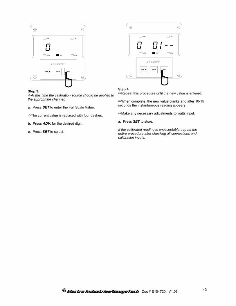
Step 3: At this time the calibration source should be applied to
the appropriate channel. a. Press SET to enter the Full Scale Value.
The current value is replaced with four dashes. b. Press ADV. for the desired digit. c. Press SET to select.
Step 4: Repeat this procedure until the new value is entered.
When complete, the new value blanks and after 10-15
seconds the instantaneous reading appears.
Make any necessary adjustments to watts input. a. Press SET to store. If the calibrated reading is unacceptable, repeat the entire procedure after checking all connections and calibration inputs.
MODE
0
ADV SET
LM1 LM2
KWHKWKWD
A C KILOWATTS
Electro Industries/GaugeTech Doc # E104720 V1.03
43
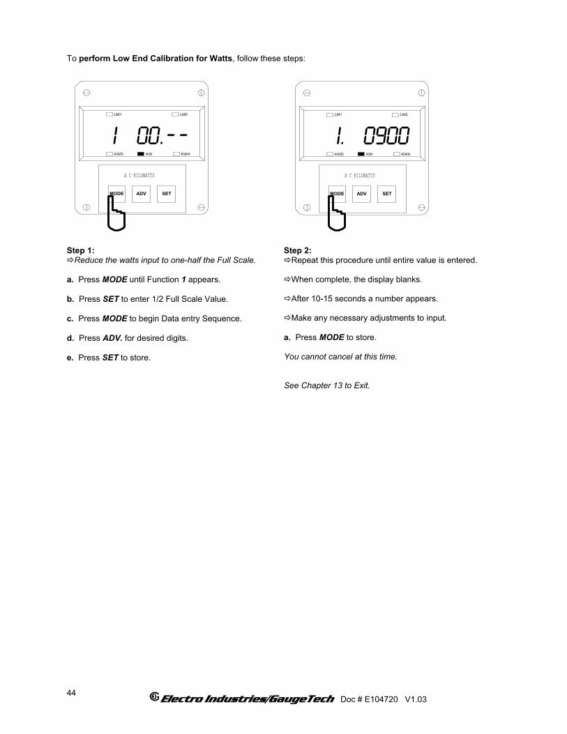
To perform Low End Calibration for Watts, follow these steps:
MODE
I 00.
ADV SET
LM1 LM2
KWHKWKWD
A C KILOWATTS
_ _
MODE
I. 0900
ADV SET
LM1 LM2
KWHKWKWD
A C KILOWATTS
Step 1:
Reduce the watts input to one-half the Full Scale. a. Press MODE until Function 1 appears. b. Press SET to enter 1/2 Full Scale Value. c. Press MODE to begin Data entry Sequence. d. Press ADV. for desired digits. e. Press SET to store.
Step 2: Repeat this procedure until entire value is entered.
When complete, the display blanks.
After 10-15 seconds a number appears.
Make any necessary adjustments to input.
a. Press MODE to store. You cannot cancel at this time. See Chapter 13 to Exit.
Electro Industries/GaugeTech Doc # E104720 V1.03
44
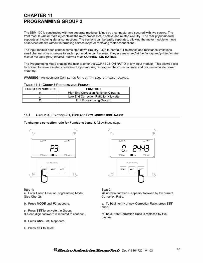
CHAPTER 11 PROGRAMMING GROUP 3 The SBM 100 is constructed with two separate modules, joined by a connector and secured with two screws. The front module (meter module) contains the microprocessors, displays and related circuitry. The rear (input module) supports all incoming signal connections. The sections can be easily separated, allowing the meter module to move or serviced off-site without interrupting service loops or removing meter connections. The input module does contain some step down circuitry. Due to normal CT tolerance and resistance limitations, small channel offsets, unique to each input module can be seen. They are measured at the factory and printed on the face of the input (rear) module, referred to as CORRECTION RATIOS. The Programming Mode enables the user to enter the CORRECTION RATIO of any input module. This allows a site technician to move a meter to a different input module, re-program the correction ratio and resume accurate power metering. WARNING: AN INCORRECT CORRECTION RATIO ENTRY RESULTS IN FALSE READINGS. TABLE 11-1: GROUP 3 PROGRAMMING FORMAT FUNCTION NUMBER FUNCTION
0. High End Correction Ratio for Kilowatts 1. Low End Correction Ratio for Kilowatts E. Exit Programming Group 3
11.1 GROUP 3, FUNCTION 0-1, HIGH AND LOW CORRECTION RATIOS To change a correction ratio for Functions 0 and 1, follow these steps:
MODE
p3.
ADV SET
LM1 LM2
KWHKWKWD
A C KILOWATTS
MODE
0. .2443
ADV SET
LM1 LM2
KWHKWKWD
A C KILOWATTS
Step 1: a. Enter Group Level of Programming Mode, (See Chp. 2). b. Press MODE until P3. appears. c. Press SET to activate the Group.
A one digit password is required to continue. d. Press ADV. until 5 appears. e. Press SET to select.
Step 2: Function number 0. appears, followed by the current
Correction Ratio. a. To begin entry of new Correction Ratio, press SET once.
The current Correction Ratio is replaced by five dashes.
Electro Industries/GaugeTech Doc # E104720 V1.03
45
MODE
0. I.0
ADV SET
LM1 LM2
KWHKWKWD
A C KILOWATTS
___
MODE
0. I.0870
ADV SET
LM1 LM2
KWHKWKWD
A C KILOWATTS
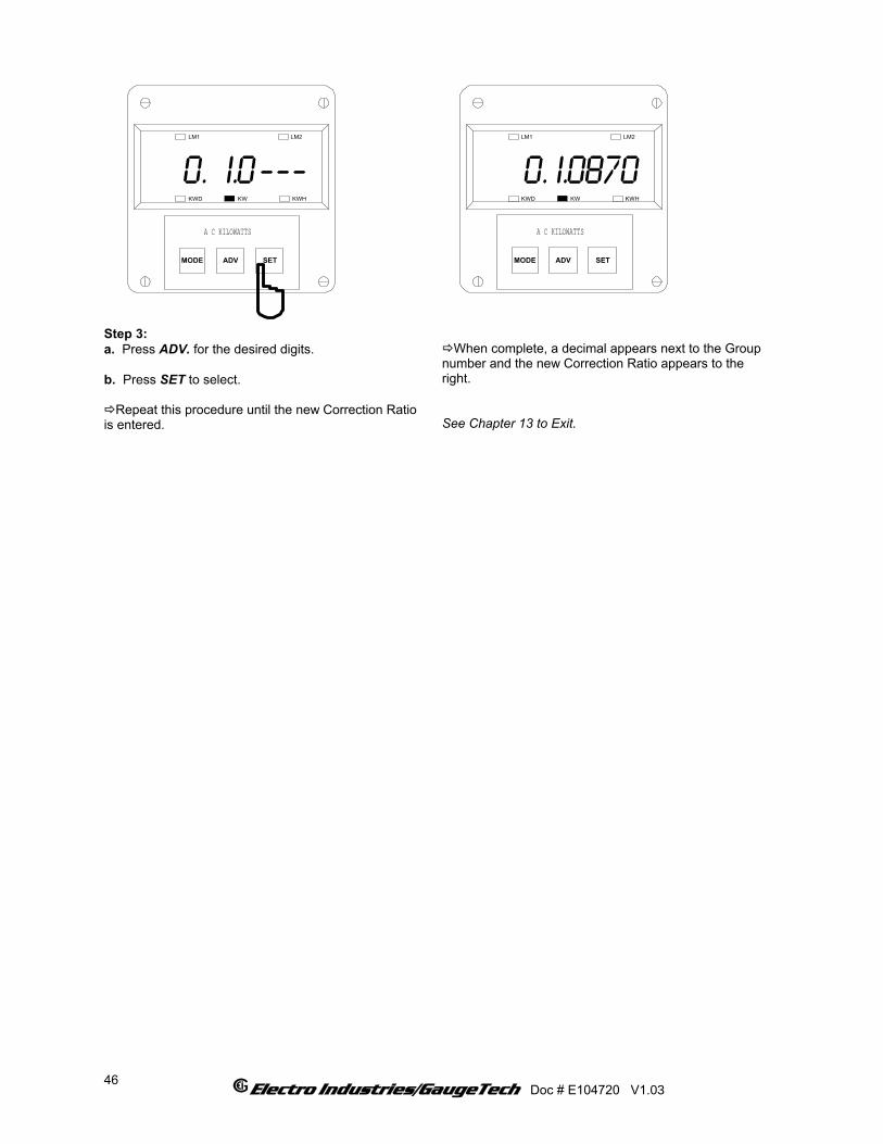
Step 3: a. Press ADV. for the desired digits. b. Press SET to select.
Repeat this procedure until the new Correction Ratio is entered.
When complete, a decimal appears next to the Group
number and the new Correction Ratio appears to the right. See Chapter 13 to Exit.
Electro Industries/GaugeTech Doc # E104720 V1.03
46

CHAPTER 12 PROGRAMMING GROUP 5 Set Limits alert the user when a particular power level changes. The Set Limits on the SBM 100 are LMT1 and LMT2. Each limit can be set at any desired level. Group 5 contains LMT1 and LMT2 Set Limit Values for Watts. The user can program the limits for positive and negative Watts. GRAPH 12-1: EXAMPLE OF LMT1/LMT2 SET LIMITS
LIMIT 1 AND LIMIT 2 SET LIMITS
TIME
POWER
0
20.0
40.0
60.0
80.0
100.0
120.0
4:00 PM 5:00 PM 6:00 PM
120.0
40.0
LM1 is triggered
LM2 is triggered50.0(KWATTS)
80.0
LM1 SET TOTRIGGER ABOVE100.0 KWATTS.
LM2 SET TOTRIGGER BELOW50.0 KWATTS.
12.1 TRIP RELAY NOTE: ALL INFORMATION PERTAINING TO TRIP RELAYS 1 AND 2 APPLIES TO THE SBM 100-3-NL ONLY. The unit has two relays linked through the program to LMT1 and LMT2 Set Limits. The relay outputs can be programmed individually to close when LMT1 and/or LMT2 is triggered. Each relay has provisions for a separate delay time (see Chapter 4).
ABOVE/BELOW Whether to trip on a signal ABOVE, or BELOW, to the selected level. TRIP RELAY 1 Whether to trip relay 1. TRIP RELAY 2 Whether to trip relay 2. LEVEL The level at which the warning mechanism trips.
TABLE 12-1: GROUP 5 PROGRAMMING FORMAT FUNCTION NUMBER FUNCTION
0. LMT1/LMT2 Set Limits for Positive Watts 1. LMT1/LMT2 Set Limits for Negative Watts E. Exit Programming Group 5
Electro Industries/GaugeTech Doc # E104720 V1.03
47
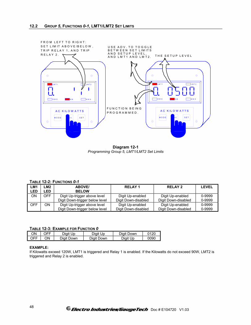
12.2 GROUP 5, FUNCTIONS 0-1, LMT1/LMT2 SET LIMITS
T H E S E T U P L E V E L
F R O M L E F T T O R IG H T :S E T L IM IT A B O V E /B E L O W ,T R IP R E L A Y 1 , A N D T R IPR E L A Y 2 .
A C K IL O W A T T S
M O D E A D V S E T
K W HK W D K W
L M T 1 L M T 2
A C K IL O W A T T S
M O D E A D V S E T
K W HK W D K W
L M T 1 L M T 2
U S E A D V . T O T O G G L EB E T W E E N S E T L IM IT SA N D S E T U P L E V E L ,A N D L M T 1 A N D L M T 2 .
F U N C T IO N B E IN GP R O G R A M M E D .
Diagram 12-1
Programming Group 5, LMT1/LMT2 Set Limits TABLE 12-2: FUNCTIONS 0-1 LM1 LED
LM2 LED
ABOVE/ BELOW
RELAY 1 RELAY 2 LEVEL
ON OFF Digit Up-trigger above level Digit Down-trigger below level
Digit Up-enabled Digit Down-disabled
Digit Up-enabled Digit Down-disabled
0-9999 0-9999
OFF ON Digit Up-trigger above level Digit Down-trigger below level
Digit Up-enabled Digit Down-disabled
Digit Up-enabled Digit Down-disabled
0-9999 0-9999
TABLE 12-3: EXAMPLE FOR FUNCTION 0 ON OFF Digit Up Digit Up Digit Down 0120 OFF ON Digit Down Digit Down Digit Up 0090 EXAMPLE: If Kilowatts exceed 120W, LMT1 is triggered and Relay 1 is enabled. If the Kilowatts do not exceed 90W, LMT2 is triggered and Relay 2 is enabled.
Electro Industries/GaugeTech Doc # E104720 V1.03
48
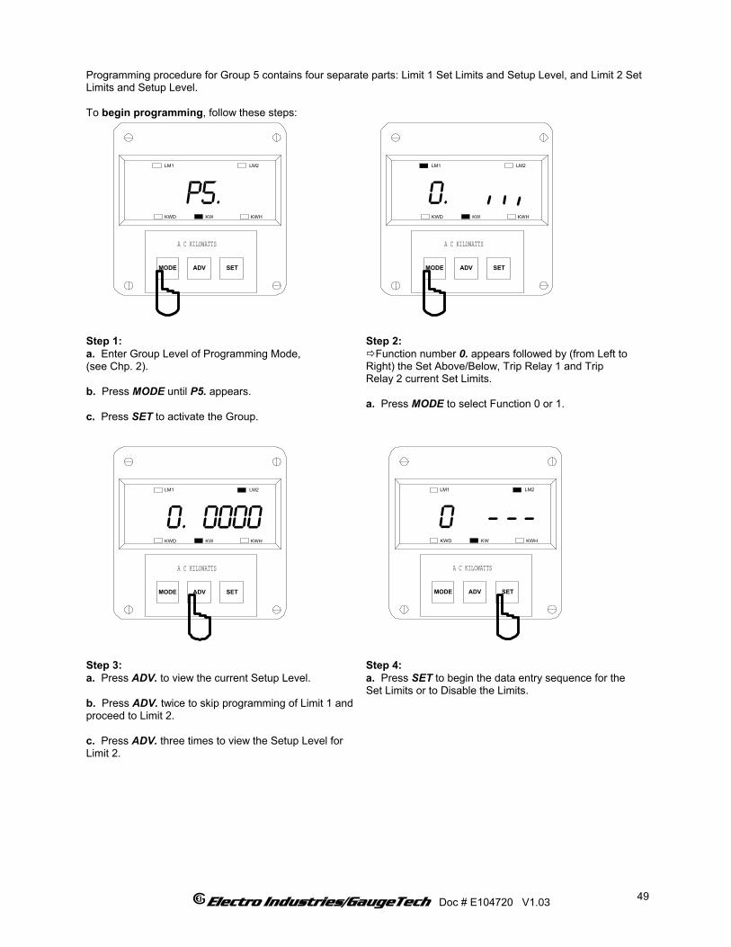
Programming procedure for Group 5 contains four separate parts: Limit 1 Set Limits and Setup Level, and Limit 2 Set Limits and Setup Level. To begin programming, follow these steps:
MODE
p5.
ADV SET
LM1 LM2
KWHKWKWD
A C KILOWATTS
MODE
0.
ADV SET
LM1 LM2
KWHKWKWD
A C KILOWATTS
___
Step 1: a. Enter Group Level of Programming Mode, (see Chp. 2). b. Press MODE until P5. appears. c. Press SET to activate the Group.
Step 2: Function number 0. appears followed by (from Left to
Right) the Set Above/Below, Trip Relay 1 and Trip Relay 2 current Set Limits. a. Press MODE to select Function 0 or 1.
MODE
0
ADV SET
LM1 LM2
KWHKWKWD
A C KILOWATTS
___
MODE
0. 0000
ADV SET
LM1 LM2
KWHKWKWD
A C KILOWATTS
Step 3: a. Press ADV. to view the current Setup Level. b. Press ADV. twice to skip programming of Limit 1 and proceed to Limit 2. c. Press ADV. three times to view the Setup Level for Limit 2.
Step 4: a. Press SET to begin the data entry sequence for the Set Limits or to Disable the Limits.
Electro Industries/GaugeTech Doc # E104720 V1.03
49

MODE
0
ADV SET
LM1 LM2
KWHKWKWD
A C KILOWATTS
___
MODE
0 06
ADV SET
LM1 LM2
KWHKWKWD
A C KILOWATTS
_ _
Step 5: b. Press ADV. to toggle the segments. c. Press SET to store.
Repeat until all information is entered.
To leave segments unchanged and to change the Limit Value, select MODE. Then proceed to Step 6.
Step 6: a. Press MODE once to Disable the Limits.
Four dashes appear next to the Function number. b. Press ADV. for desired digits. c. Press SET to store.
Repeat until all information is entered. d. After entering all four digits, the display will revert back to showing segments. Press ADV to see the Limit Value. e. After the fourth digit is stored, the display reverts back to the segment setting and the decimal point will reappear after the Function 0 digit. See Chapter 13 to Exit.
Electro Industries/GaugeTech Doc # E104720 V1.03
50
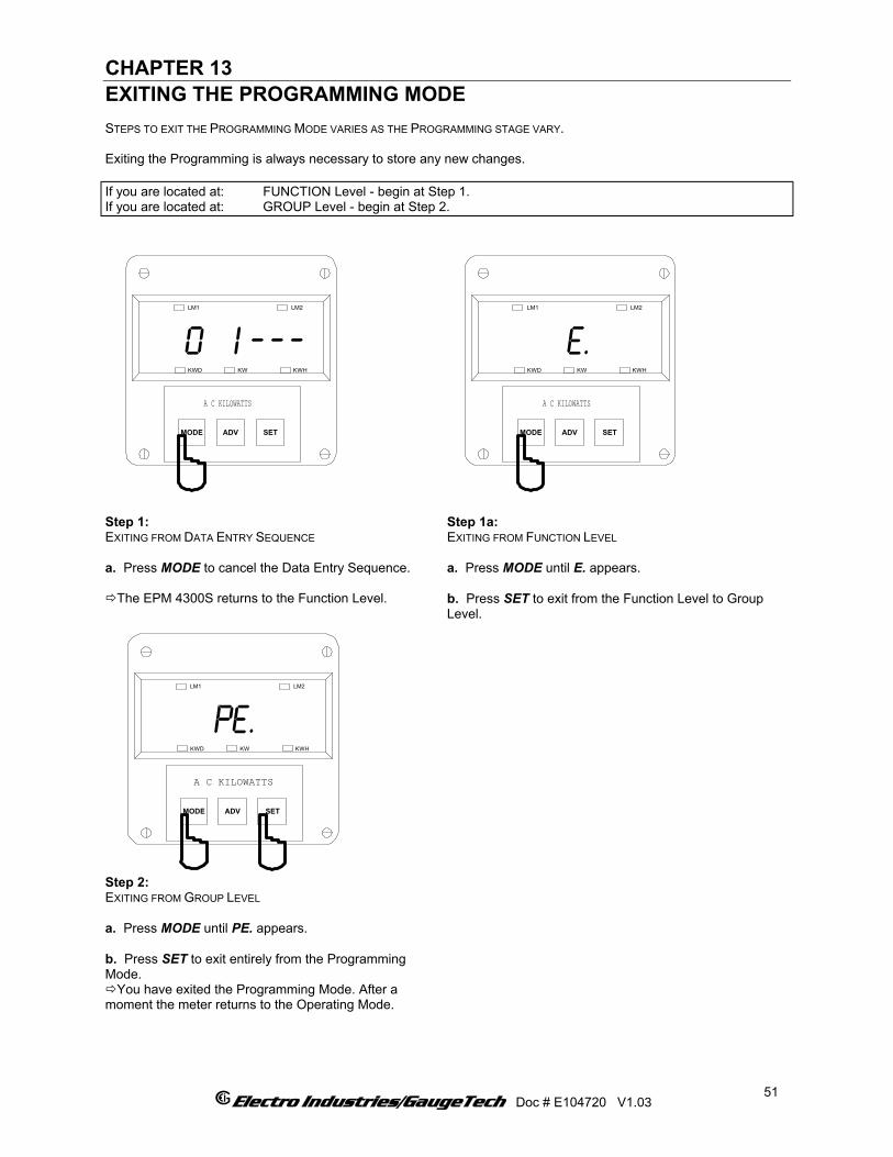
CHAPTER 13 EXITING THE PROGRAMMING MODE STEPS TO EXIT THE PROGRAMMING MODE VARIES AS THE PROGRAMMING STAGE VARY. Exiting the Programming is always necessary to store any new changes. If you are located at: FUNCTION Level - begin at Step 1. If you are located at: GROUP Level - begin at Step 2.
MODE
0 I
ADV SET
LM1 LM2
KWHKWKWD
A C KILOWATTS
_ __
MODE
e.
ADV SET
LM1 LM2
KWHKWKWD
A C KILOWATTS
Step 1: EXITING FROM DATA ENTRY SEQUENCE a. Press MODE to cancel the Data Entry Sequence.
The EPM 4300S returns to the Function Level.
Step 1a: EXITING FROM FUNCTION LEVEL a. Press MODE until E. appears. b. Press SET to exit from the Function Level to Group Level.
Step 2: EXITING FROM GROUP LEVEL a. Press MODE until PE. appears. b. Press SET to exit entirely from the Programming Mode.
You have exited the Programming Mode. After a moment the meter returns to the Operating Mode.
MODE
pe.
ADV SET
LM1 LM2
KWHKWKWD
A C KILOWATTS
Electro Industries/GaugeTech Doc # E104720 V1.03 51

Electro Industries/GaugeTech Doc # E104720 V1.03
52
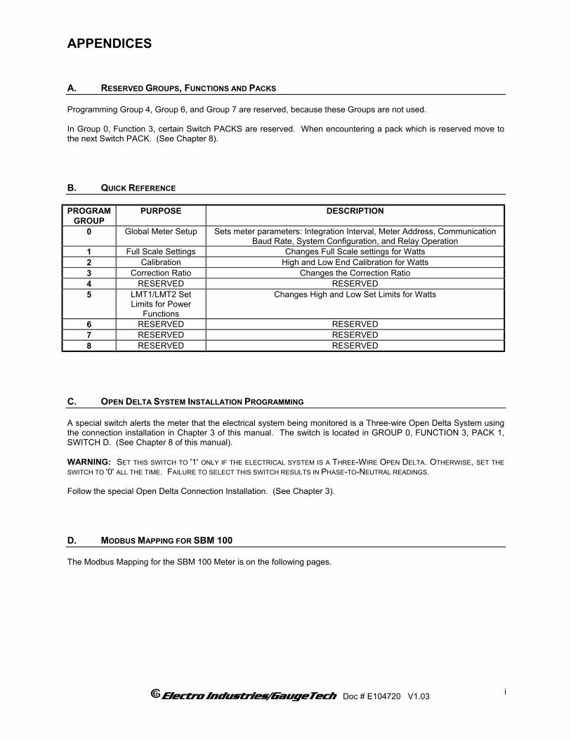
APPENDICES A. RESERVED GROUPS, FUNCTIONS AND PACKS Programming Group 4, Group 6, and Group 7 are reserved, because these Groups are not used. In Group 0, Function 3, certain Switch PACKS are reserved. When encountering a pack which is reserved move to the next Switch PACK. (See Chapter 8). B. QUICK REFERENCE PROGRAM
GROUP PURPOSE DESCRIPTION
0 Global Meter Setup Sets meter parameters: Integration Interval, Meter Address, Communication Baud Rate, System Configuration, and Relay Operation
1 Full Scale Settings Changes Full Scale settings for Watts 2 Calibration High and Low End Calibration for Watts 3 Correction Ratio Changes the Correction Ratio 4 RESERVED RESERVED 5 LMT1/LMT2 Set
Limits for Power Functions
Changes High and Low Set Limits for Watts
6 RESERVED RESERVED 7 RESERVED RESERVED 8 RESERVED RESERVED
C. OPEN DELTA SYSTEM INSTALLATION PROGRAMMING A special switch alerts the meter that the electrical system being monitored is a Three-wire Open Delta System using the connection installation in Chapter 3 of this manual. The switch is located in GROUP 0, FUNCTION 3, PACK 1, SWITCH D. (See Chapter 8 of this manual). WARNING: SET THIS SWITCH TO '1' ONLY IF THE ELECTRICAL SYSTEM IS A THREE-WIRE OPEN DELTA. OTHERWISE, SET THE SWITCH TO '0' ALL THE TIME. FAILURE TO SELECT THIS SWITCH RESULTS IN PHASE-TO-NEUTRAL READINGS. Follow the special Open Delta Connection Installation. (See Chapter 3).
D. MODBUS MAPPING FOR SBM 100 The Modbus Mapping for the SBM 100 Meter is on the following pages.
Electro Industries/GaugeTech Doc # E104720 V1.03
i
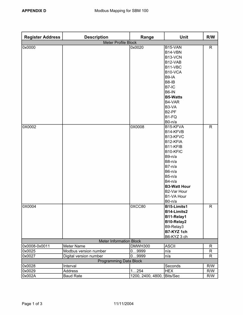
APPENDIX D Modbus Mapping for SBM 100
Register Address Description Range Unit R/W
0x0000
0x0020 B15-VANB14-VBNB13-VCNB12-VABB11-VBCB10-VCAB9-IAB8-IBB7-ICB6-INB5-WattsB4-VARB3-VAB2-PFB1-FQB0-n/a
R
0X0002 0X0008 B15-KFVAB14-KFVBB13-KFVCB12-KFIAB11-KFIBB10-KFICB9-n/aB8-n/aB7-n/aB6-n/aB5-n/aB4-n/aB3-Watt HourB2-Var HourB1-VA HourB0-n/a
R
0X0004 0XCC80 B15-Limits1B14-Limits2B11-Relay1B10-Relay2B9-Relay3B7-KYZ 1chB6-KYZ 3 ch
R
0x0008-0x0011 Meter Name DMWH300 ASCII R0x0025 Modbus version number 0…9999 n/a R0x0027 Digital version number 0…9999 n/a R
0x0028 Interval Seconds R/W0x0029 Address 1…254 HEX R/W0x002A Baud Rate 1200, 2400, 4800, 9Bits/Sec R/W
Meter Profile Block
Meter Information Block
Programming Data Block
Page 1 of 3 11/11/2004

APPENDIX D Modbus Mapping for SBM 100
Register Address Description Range Unit R/W0x002B Config 0xFFFF B13-MW
B11-LZB10-RSTB8-DLTB7-KYZ for WHB6-KYZ for -WHB4-Modbus/EI protocolB3-RLY1B2-RLY2B1-COMB0-DC
R/W
0x002C Watt Full Scale 0…2000 HEX R/W0x002F Power DP only High byte Watt DP R/W
0x0030
Set Above/Below Lim1
bit 1 : Belowbit 0 : Above
B5-Positive Limit 1B4-Negative Limit 1
R/W
0x0031 Set Above/Below Lim2
bit 1 : Belowbit 0 : Above
B5-Positive Limit 2B4-Negative Limit 2
R/W
0x0046 Limit 1 Watt Value 0…2000 HEX R/W0x0047 Limit 2 Watt Value 0…2000 HEX R/W0x0050 Limit 1 Negative Watt Value 0…2000 HEX R/W0x0051 Limit 2 Negative Watt Value 0…2000 HEX R/W0x0070 RLY1 Lim1
bit 1 : Turn on Relaybit 0 : Turn off Relay
B5-Positive Limit 1B4-Negative Limit 1
R/W
0x0071 RLY1 Lim2
bit 1 : Turn on Relaybit 0 : Turn off Relay
B5-Positive Limit 2B4-Negative Limit 2
R/W
0x0072 RLY2 Lim1
bit 1 : Turn on Relaybit 0 : Turn off Relay
B5-Positive Limit 1B4-Negative Limit 1
R/W
0x0073 RLY2 Lim2
bit 1 : Turn on Relaybit 0 : Turn off Relay
B5-Positive Limit 2B4-Negative Limit 2
R/W
0x0074 Delay on Relays, Each byte has delay for relays
0…250, 0…250 Seconds R/W
0x0120 Inst. Watt -9999…9999 HEX R0x0147 Watt Average -9999…9999 HEX R0x016E Max. Watt 0…9999 HEX R
0x01B2-0x01B9 Watt Hour 0~19999999.99 ASCII R
DAXI Data Block
Hour Block
Page 2 of 3 11/11/2004
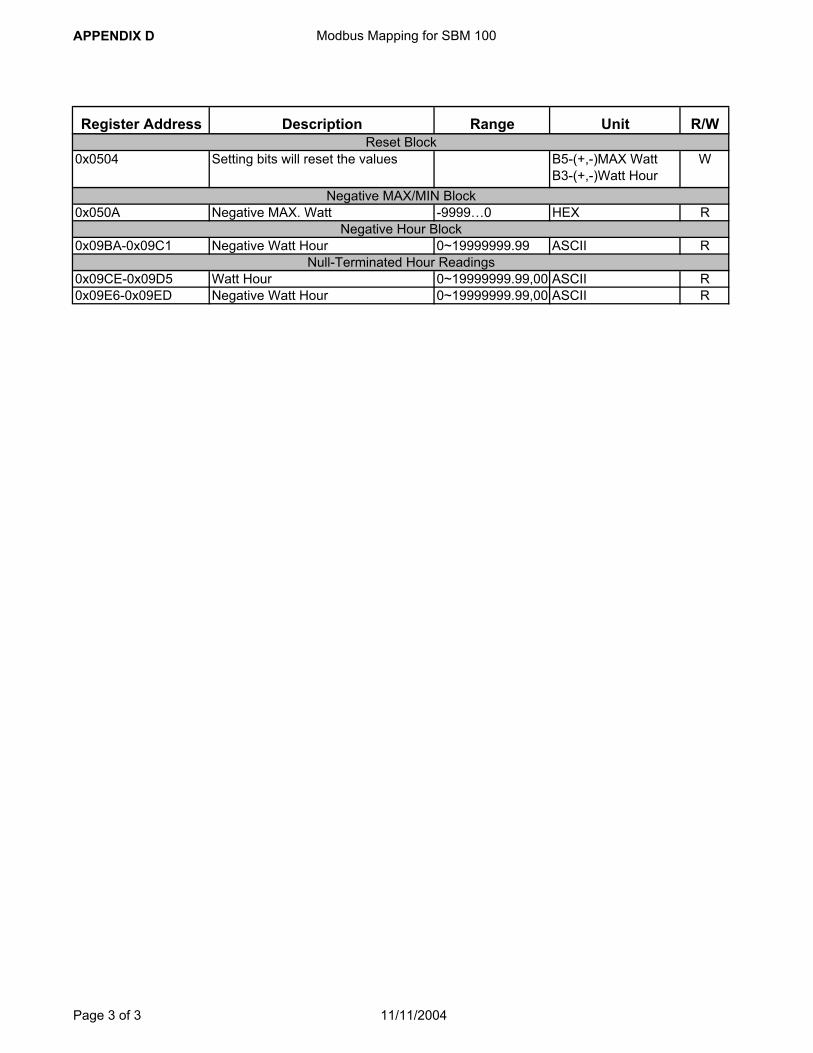
APPENDIX D Modbus Mapping for SBM 100
Register Address Description Range Unit R/W
0x0504 Setting bits will reset the values B5-(+,-)MAX WattB3-(+,-)Watt Hour
W
0x050A Negative MAX. Watt -9999…0 HEX R
0x09BA-0x09C1 Negative Watt Hour 0~19999999.99 ASCII R
0x09CE-0x09D5 Watt Hour 0~19999999.99,00 ASCII R0x09E6-0x09ED Negative Watt Hour 0~19999999.99,00 ASCII R
Negative MAX/MIN Block
Negative Hour Block
Null-Terminated Hour Readings
Reset Block
Page 3 of 3 11/11/2004