Saturday, March 19, 2016 Newport County, Rhode … MCA FCLC LNG Fueled Vessel... · Title: LNG FUEL...
26
Copyright © 2016 United States Maritime Resource Center, Inc. All Rights Reserved. 1 Flammable Cryogenic Liquid Carriers Thank You to the Seminar Sponsor Seminar Provider and Host Saturday, March 19, 2016 Newport County, Rhode Island, USA
Transcript of Saturday, March 19, 2016 Newport County, Rhode … MCA FCLC LNG Fueled Vessel... · Title: LNG FUEL...

Copyright © 2016 United States Maritime Resource Center, Inc. All Rights Reserved. 1Copyright © 2016 United States Maritime Resource Center, Inc. All Rights Reserved. 1
Flammable Cryogenic Liquid Carriers
Thank You to the Seminar Sponsor
Seminar Provider and Host
Saturday, March 19, 2016
Newport County, Rhode Island, USA

Copyright © 2016 United States Maritime Resource Center, Inc. All Rights Reserved. 2Copyright © 2015 United States Maritime Resource Center, Inc. All Rights Reserved. 2
Agenda & Topics
Morning 0830 - 1230
01 Introduction
02 LNG Properties and Characteristics
03 LNG Hazards
04 LNG Industry overview
Afternoon
1330 – 1630 Interactive Work Shop
05 LNG Fuel Vessel Design and Construction
06 Fuel Tanks and Fuel Supply Systems
07 Gas Atmosphere Measuring, Control and Monitoring,
Venting, Inerting, unique repair hazards
Copyright © 2016 United States Maritime Resource Center, Inc. All Rights Reserved. 3Copyright © 2016 United States Maritime Resource Center, Inc. All Rights Reserved. 3
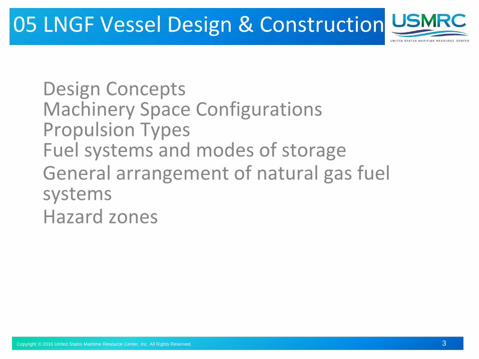
Design ConceptsMachinery Space ConfigurationsPropulsion TypesFuel systems and modes of storageGeneral arrangement of natural gas fuel systemsHazard zones
05 LNGF Vessel Design & Construction
Copyright © 2016 United States Maritime Resource Center, Inc. All Rights Reserved. 4Copyright © 2016 United States Maritime Resource Center, Inc. All Rights Reserved. 4
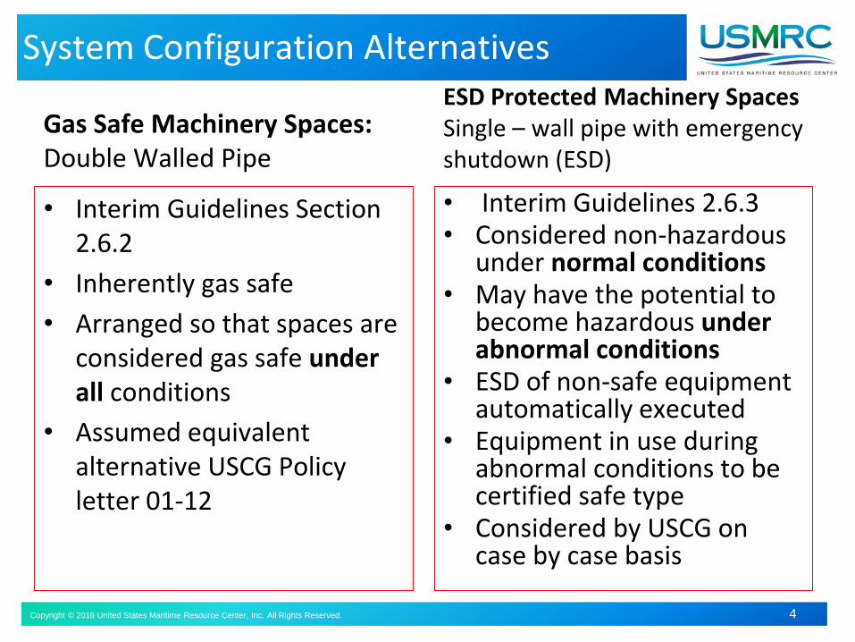
System Configuration Alternatives
Gas Safe Machinery Spaces:Double Walled Pipe
• Interim Guidelines Section 2.6.2
• Inherently gas safe
• Arranged so that spaces are considered gas safe under all conditions
• Assumed equivalent alternative USCG Policy letter 01-12
ESD Protected Machinery SpacesSingle – wall pipe with emergency shutdown (ESD)
• Interim Guidelines 2.6.3• Considered non-hazardous
under normal conditions• May have the potential to
become hazardous under abnormal conditions
• ESD of non-safe equipment automatically executed
• Equipment in use during abnormal conditions to be certified safe type
• Considered by USCG on case by case basis

Copyright © 2016 United States Maritime Resource Center, Inc. All Rights Reserved. 5
Gas Safe Machinery Spaces
Inherently Gas Safe
• All gas supply piping in machinery space double wall or ducted (gas tight enclosure)
• Secondary independent fuel supply available in case of gas shutdown (Diesel)
• Independent & separate supply for multiple engines
Double Walled Pipe:

Copyright © 2016 United States Maritime Resource Center, Inc. All Rights Reserved. 6Copyright © 2016 United States Maritime Resource Center, Inc. All Rights Reserved. 6
Gas- fueled engine room, ESD protected
ESD protected machinery space
Gas fueled engine room, ESD protected
Single wall pipe
Simple geometric shape
Minimum amount of equipment installed
Explosion protection between machinery spaces
Low pressure systems only (<10Bar)
Non Hazardous under normal conditions, potential to become hazardous under certain abnormal conditions
Single wall piping
2 or more machinery spaces
40% of propulsion power / electrical supply in case of fuel supply shutdown
Automatic shutdown of fuel supply on gas detection
Automatic disconnect of non-explosion proof equipment

Copyright © 2016 United States Maritime Resource Center, Inc. All Rights Reserved. 7
Propulsion Systems
Two types of engine are defined in the Interim Guidelines:
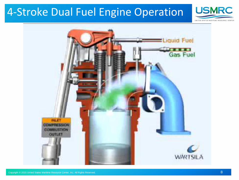
Dual Fuel:• 1.3.6 Engines that can burn natural gas and fuel oil
simultaneously or operate on oil fuel or gas only
Single Gas Fuel:• 1.3.30 Single gas fuel engines means a power
generating engine capable of operating on gas only and not able to switch over to oil fuel operation
Copyright © 2016 United States Maritime Resource Center, Inc. All Rights Reserved. 8Copyright © 2015 United States Maritime Resource Center, Inc. All Rights Reserved. 8
4-Stroke Dual Fuel Engine Operation

Copyright © 2016 United States Maritime Resource Center, Inc. All Rights Reserved. 9Copyright © 2016 United States Maritime Resource Center, Inc. All Rights Reserved. 9
Spark ignited single gas fuel Engine
Rolls Royce
Bergen C26:33
Design Requirements:
• Fuel gas not admitted until ignition activated and at set min rotational speed
• Automatic shutoff and purge away from exhaust system if ignition not detected
• For shutdown, gas fuel supply should be shut off not later than simultaneously with the ignition
• Ignition system active until engine stopped
Copyright © 2016 United States Maritime Resource Center, Inc. All Rights Reserved. 10Copyright © 2016 United States Maritime Resource Center, Inc. All Rights Reserved. 10
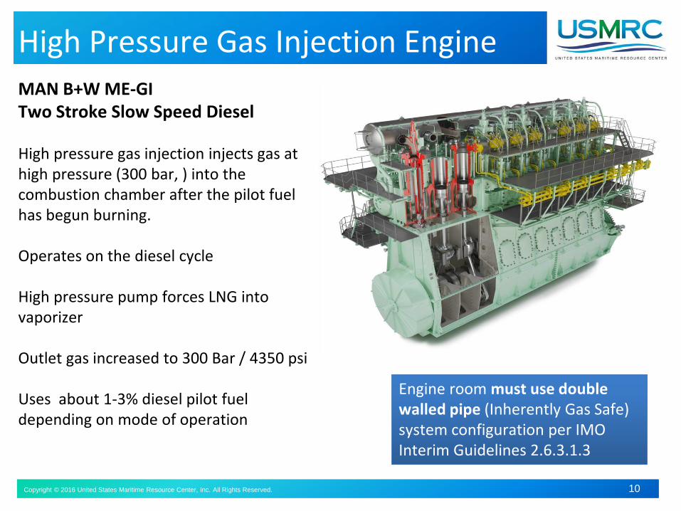
High Pressure Gas Injection Engine
MAN B+W ME-GITwo Stroke Slow Speed Diesel
High pressure gas injection injects gas at high pressure (300 bar, ) into the combustion chamber after the pilot fuel has begun burning.
Operates on the diesel cycle
High pressure pump forces LNG into vaporizer
Outlet gas increased to 300 Bar / 4350 psi
Uses about 1-3% diesel pilot fuel depending on mode of operation
Engine room must use double walled pipe (Inherently Gas Safe) system configuration per IMO Interim Guidelines 2.6.3.1.3

Copyright © 2016 United States Maritime Resource Center, Inc. All Rights Reserved. 11Copyright © 2016 United States Maritime Resource Center, Inc. All Rights Reserved. 11
Low Pressure Fuel Gas Supply System
Liquid to evap
Bunker StationVapor ReturnLiquid Fill
Spray bar
Tank ConnectionSpace
Pressurized vapor to tank
Vapor to evap
For low pressure Otto cycle engines
Liquid fuel tank operating pressure controlled by operator pressure setting
during bunkering
Operating pressure controlled by engine power demand during operation via
feedback input to pressure build up evaporator
Bottom fill line

Copyright © 2016 United States Maritime Resource Center, Inc. All Rights Reserved. 12Copyright © 2016 United States Maritime Resource Center, Inc. All Rights Reserved. 12
High Pressure Fuel Gas Supply System
LNG
TANKHFO
TANK
NBOG
Compressor
Fuel containmentFuel gas supply systemPrime mover
300 bar
Fuel gas
HFO
• For high pressure direct injection (Diesel) engines
• Greater than 10 Bar pressure – Double walled pipe only
• High pressure pump to vaporizer
• High pressure gas downstream of vaporizer
• Fuel gas supply rate according to engine power demand
• CNG receiver provided to dampen demand variability

Copyright © 2016 United States Maritime Resource Center, Inc. All Rights Reserved. 13
Tank Connection Space (TCS)
Gas tight enclosure containing all
tank connections, fittings, flanges
and tank valves
Constructed of cryogenic
temperature resistant material
Bilge well with high level indicator
and low temperature sensor,
Not normally accessible, not to be
entered by personnel unless
checked for sufficient oxygen and
absence of explosive atmosphere
• Bolted hatch unless direct
access from open deck
Also referred to as “Cold Box”
• Mechanical ventilation, 30 air
changes/hr
• Permanent gas detection
• Fixed fire detection

Copyright © 2016 United States Maritime Resource Center, Inc. All Rights Reserved. 14Copyright © 2016 United States Maritime Resource Center, Inc. All Rights Reserved. 14
Gas Valve Unit (GVU )
Automatic vent valves ME X 05 and 06 -vent to atmosphere
Purge Valve ME X 07 -nitrogen purge
ME fuel regulating valve ME X 08
Supplies conditioned gas from Pressure Build-up Evaporator and Fuel Gas Heater at required
temperature and pressure
Automatically adjusts flow according to throttle setting / fuel consumer demand
Fully integrated with safety shutdown system
Block and bleed fitted with vent to atmosphere
Copyright © 2016 United States Maritime Resource Center, Inc. All Rights Reserved. 15Copyright © 2016 United States Maritime Resource Center, Inc. All Rights Reserved. 15
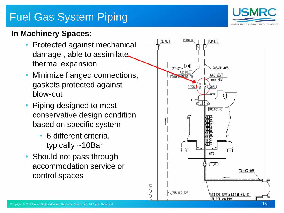
Fuel Gas System Piping
In Machinery Spaces:
• Protected against mechanical
damage , able to assimilate
thermal expansion
• Minimize flanged connections,
gaskets protected against
blow-out
• Piping designed to most
conservative design condition
based on specific system
• 6 different criteria,
typically ~10Bar
• Should not pass through
accommodation service or
control spaces

Copyright © 2016 United States Maritime Resource Center, Inc. All Rights Reserved. 16Copyright © 2016 United States Maritime Resource Center, Inc. All Rights Reserved. 16
Fuel Gas System Piping
Outside of machinery
spaces:
In enclosed spaces, ventilated
double walled or ducted:
• 30 air changes/hour,
• inlet in open air away
from ignition sources
Piping in open air, protected
from mechanical damage
High pressure gas lines
protected to minimize
personnel risk in case of
rupture

Copyright © 2016 United States Maritime Resource Center, Inc. All Rights Reserved. 17Copyright © 2016 United States Maritime Resource Center, Inc. All Rights Reserved. 17
General Arrangement: OSV
Tank Location Placed as close as possible to the centerline1) Minimum the lesser of B/5 and
11.5m from ship side2) Minimum B/15 and 2m from
bottom plating3) Not less than 760mm from the
shell plating

Copyright © 2016 United States Maritime Resource Center, Inc. All Rights Reserved. 1818
General Arrangement: Ferry

Copyright © 2016 United States Maritime Resource Center, Inc. All Rights Reserved. 1919
General Arrangement: Container Ship

Copyright © 2016 United States Maritime Resource Center, Inc. All Rights Reserved. 20Copyright © 2016 United States Maritime Resource Center, Inc. All Rights Reserved. 20
Hazardous Zone Basics
Class I, Division 1 “Hazard Likely”Ignitable concentrations of flammable gases or vapors may exist under normal operating conditions; or frequently
Class I, Division 2 “Hazard not Likely”liquids, vapors, or gases will normally be confined, but can escape only in case of accidental rupture or in case of abnormal operation

Copyright © 2016 United States Maritime Resource Center, Inc. All Rights Reserved. 21Copyright © 2016 United States Maritime Resource Center, Inc. All Rights Reserved. 21
Location of Electrical Equipment
• The purpose of Hazardous Zone designation is to determine the safe location and type of electrical equipment that can be used in the zone
• Excludes ignition sources where the potential for a flammable gas atmosphere exists
• It is also used in determining the minimum extent of safety zones for LNG Fuel Transfer

Copyright © 2016 United States Maritime Resource Center, Inc. All Rights Reserved. 22Copyright © 2016 United States Maritime Resource Center, Inc. All Rights Reserved. 22
IEC Hazardous Zone Definitions
Zone Designations Defined Zone 0 explosive gas atmosphere / flammable gas present continuously or for long periods
Zone 1 explosive gas atmosphere / flammable gas is likely to occur in normal operation
Zone 2 explosive gas atmosphere / flammable gas not likely to occur in normal operation –or – likely to occur only infrequently and for a short period

Copyright © 2016 United States Maritime Resource Center, Inc. All Rights Reserved. 23Copyright © 2016 United States Maritime Resource Center, Inc. All Rights Reserved. 23
Zone 0
1) The interiors of LNG tanks, any pipework or pressure relief or other venting systems for LNG tanks
2) Natural gas pump room or compressor rooms3) Areas on open deck or semi-enclosed spaces within 0.5m of
any pump or compressor room entrance / ventilation inlet or outlet
4) Enclosed / semi-enclosed space opening into a zone 0) location

Copyright © 2016 United States Maritime Resource Center, Inc. All Rights Reserved. 24Copyright © 2016 United States Maritime Resource Center, Inc. All Rights Reserved. 24
Zone 1
Zone 11) A tank room2) A zone on the weather deck or
semi-enclosed space within 3.0m of any LNG Tank outlet, gas or vapor outlet, gas fuel pipe flange, ventilation hood, ventilated pipe or duct outlet
3) Areas on the open deck 1.0 meter beyond item (3) Zone 0 locations
4) Areas on the open deck within spillage coamings surrounding gas bunker manifold valves and 3 m beyond to a height of 2.4m
5) Enclosed space having an openingin any Zone 1 location
6) Enclosed space in which pipes containing gas are located
Zone 0 Item 3:
Areas on open deck…within 0.5m of
pump or compressor room entrance
or ventilation inlet/outlet

Copyright © 2016 United States Maritime Resource Center, Inc. All Rights Reserved. 25Copyright © 2016 United States Maritime Resource Center, Inc. All Rights Reserved. 25
Zone 2
1) A zone on the weather deck within 1.5m of the areas in item 2 through 4 of the zone 1 locations listed above
2) A zone within 2.4 m of the outer surface of a LNG tank where the surface is exposed to weather
3) An enclosed space that shares a boundary with a tank room containing a tank required to have a secondary barrier

Copyright © 2016 United States Maritime Resource Center, Inc. All Rights Reserved. 26Copyright © 2016 United States Maritime Resource Center, Inc. All Rights Reserved. 26
End of Section
Questions?