Satoshi Okamoto Department of Physics, Columbia University Electronic Reconstruction in Correlated...
24
Satoshi Okamoto Department of Physics, Columbia University Electronic Reconstruction in Correlated Electron Heterostructures: rds a general understanding of correlated electr at interface and surface Support: JSPS & DOE ER 46169 Refs.: .J.M., Nature 428, 630 (2004); PRB 70, 075101; 241104(R) (200 Collaborator: Andrew J. Millis cussion: H.Monien, M.Potthoff, G.Kotliar, A.Ohtomo, H.Hw
-
Upload
poppy-brooks -
Category
Documents
-
view
215 -
download
1
Transcript of Satoshi Okamoto Department of Physics, Columbia University Electronic Reconstruction in Correlated...
Satoshi OkamotoDepartment of Physics, Columbia University
Electronic Reconstruction in Correlated Electron Heterostructures:
Towards a general understanding of correlated electrons at interface and surface
Support: JSPS & DOE ER 46169
Journal Refs.: S.O. & A.J.M., Nature 428, 630 (2004); PRB 70, 075101; 241104(R) (2004).
Collaborator: Andrew J. Millis
Discussion: H.Monien, M.Potthoff, G.Kotliar, A.Ohtomo, H.Hwang
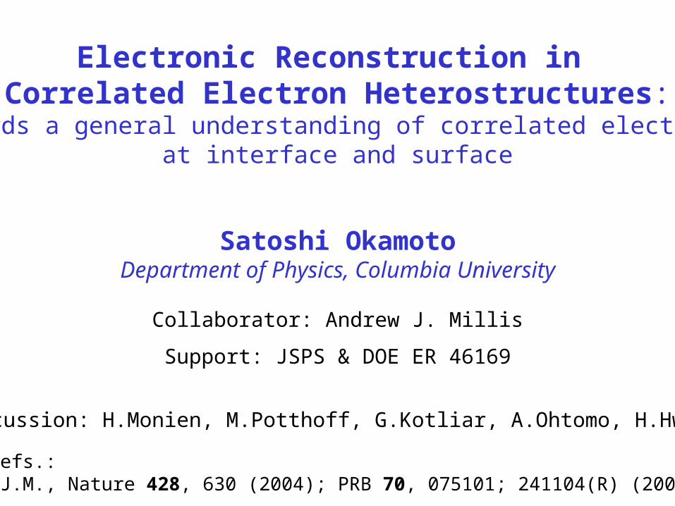
Interface Science including Correlated-Electron Systems(ex. High-Tc cuprates, CMR manganites…)
Important for Application: spin valve, Josephson junction… Experiment (surface* sensitive): ARPES, STM,…
Tunneling magnetoresistance (TMR)(La,Sr)MnO3/SrTiO3/(La,Sr)MnO3
2
2
1
2
)(
)()0(TMR
P
P
H
HH
High TMR ratio (high polarization P ~ 90%) is only achieved at very low T <<bulk TC~370K
Photoemission experiment on CaVO3 and SrVO3
Maiti et al., Europhys. Lett. 55, 246 (2001).Bowen et al., Appl. Phys. Lett. 82, 233 (2003).
Dependent on photon energySurface bulk
Interface phases look different from bulk…
SrTiO3
(La,Sr)MnO3
(La,Sr)MnO3
SrTiO3
(La,Sr)MnO3
(La,Sr)MnO3
curr
ent
H
(0) (H)
*Surface= interface between material & vacuum
Theory: LiebschSchwieger, Potthoff
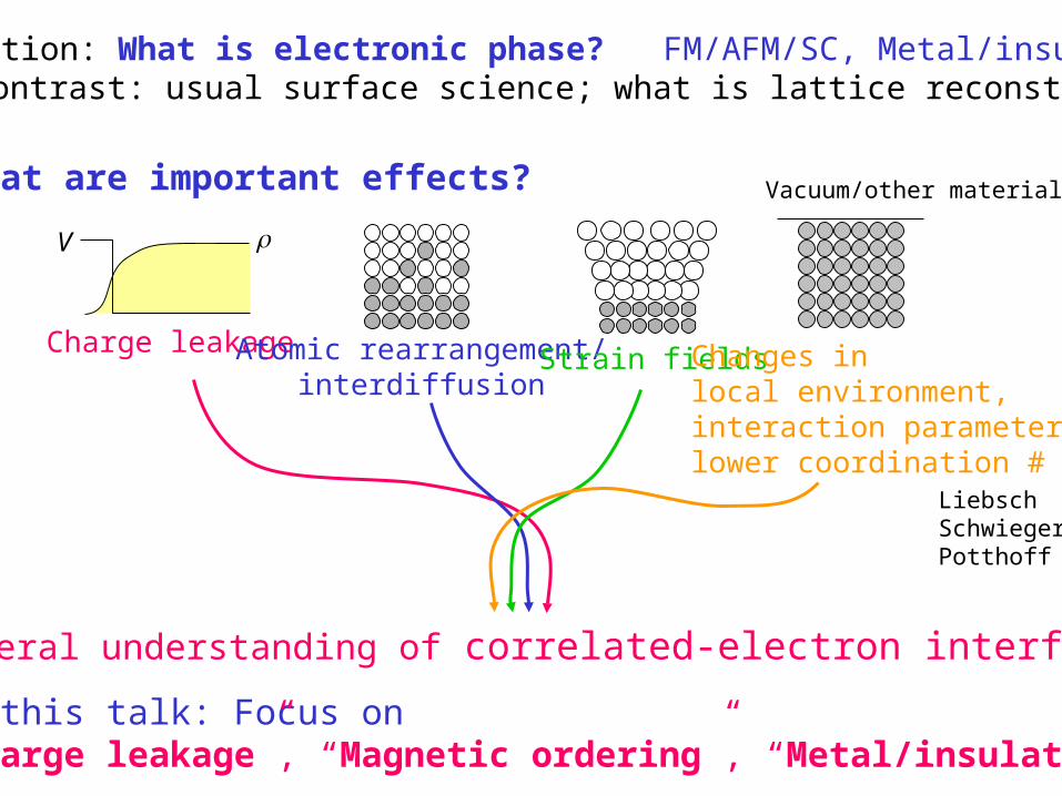
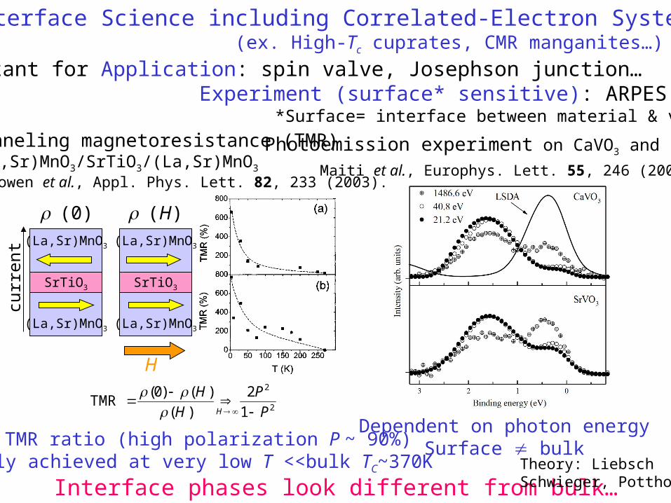
Key question: What is electronic phase? FM/AFM/SC, Metal/insulator,…(contrast: usual surface science; what is lattice reconstruction)
V
Charge leakage Atomic rearrangement/interdiffusion
Strain fields
In this talk: Focus on“Charge leakage”, “Magnetic ordering”, “Metal/insulator”
Changes in local environment,interaction parameters,lower coordination #
Vacuum/other material
LiebschSchwiegerPotthoff
What are important effects?
General understanding of correlated-electron interface
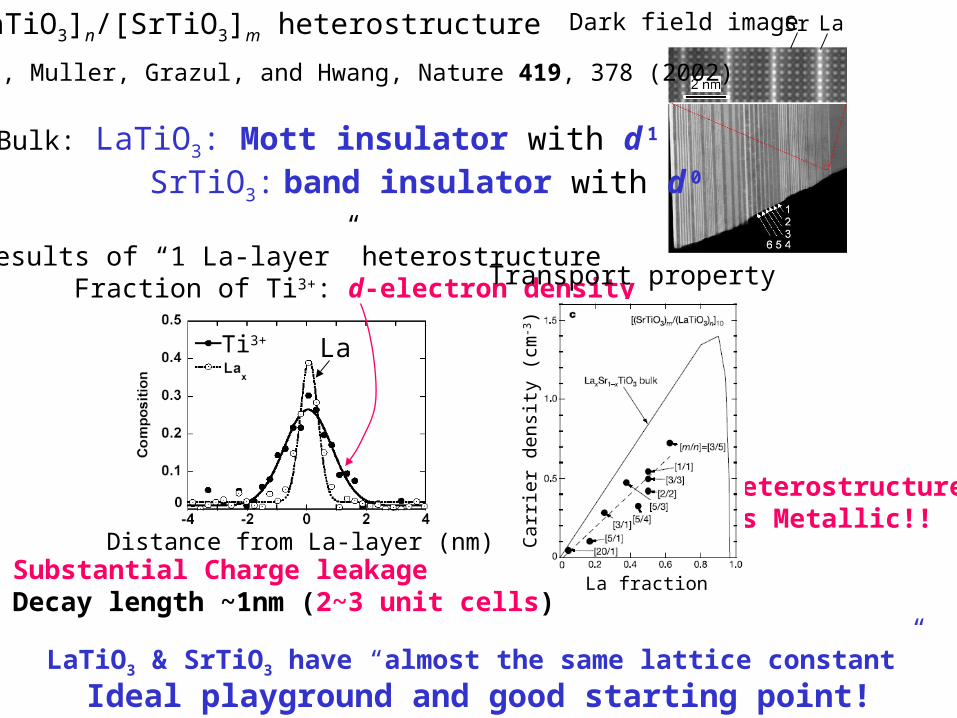
Bulk: LaTiO3: Mott insulator with d 1
SrTiO3: band insulator with d 0
Dark field image Sr La
EELS results of “1 La-layer” heterostructure Fraction of Ti3+: d-electron density
Substantial Charge leakageDecay length ~1nm (2~3 unit cells)
Heterostructure is Metallic!!
[LaTiO3]n/[SrTiO3]m heterostructure
Ohtomo, Muller, Grazul, and Hwang, Nature 419, 378 (2002)
Transport property
Ideal playground and good starting point!
Distance from La-layer (nm)C
arrie
r de
nsi
ty (
cm-3)
La fraction
Ti3+ La
LaTiO3 & SrTiO3 have “almost the same lattice constant”
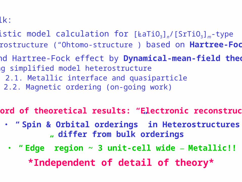
Key word of theoretical results: “Electronic reconstruction”
・ “ Spin & Orbital orderings” in Heterostructuresdiffer from bulk orderings
・ “ Edge” region ~ 3 unit-cell wide — Metallic!!
*Independent of detail of theory*
This talk:
1. Realistic model calculation for [LaTiO3]n/[SrTiO3]m-type
heterostructure (“Ohtomo-structure”) based on Hartree-Fock
2. Beyond Hartree-Fock effect by Dynamical-mean-field theory using simplified model heterostructure 2.1. Metallic interface and quasiparticle 2.2. Magnetic ordering (on-going work)
1. Realistic model calculation for [LaTiO3]n/[SrTiO3]m-type heterostructure (“Ohtomo-structure”)
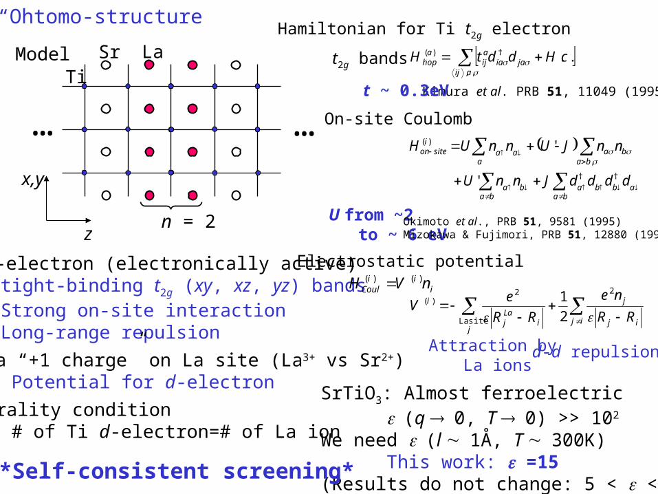
Model
Ti d-electron (electronically active) ・ tight-binding t2g (xy, xz, yz) bands ・ Strong on-site interaction ・ Long-range repulsion
Extra “+1 charge” on La site (La3+ vs Sr2+) ・ Potential for d-electron
Neutrality condition ・ # of Ti d-electron=# of La ion
LaTi
Sr
n = 2z
x,y
… …
ij ij
j
ji
Laj
i
RR
ne
RR
eV
2
siteLa
2)(
2
1
baabba
baba
baba
aaa
isiteon
ddddJnnU
nnJUnnUH
††
,
)(
'
'
iii
Coul nVH )()(
Hamiltonian for Ti t2g electron
t2g bands
Electrostatic potential
On-site Coulomb
,,
†)( ..aij
jaiaaij
ahop cHddtH
Kimura et al. PRB 51, 11049 (1995)
Attraction by La ions
d-d repulsion
t ~ 0.3eV
U from ~2 to ~ 6 eV
Okimoto et al., PRB 51, 9581 (1995)Mizokawa & Fujimori, PRB 51, 12880 (1995)
SrTiO3: Almost ferroelectric(q 0, T 0) >> 102
We need (l 1Å, T 300K)This work: =15
(Results do not change: 5 < < 40)*Self-consistent screening*
“Ohtomo-structure”
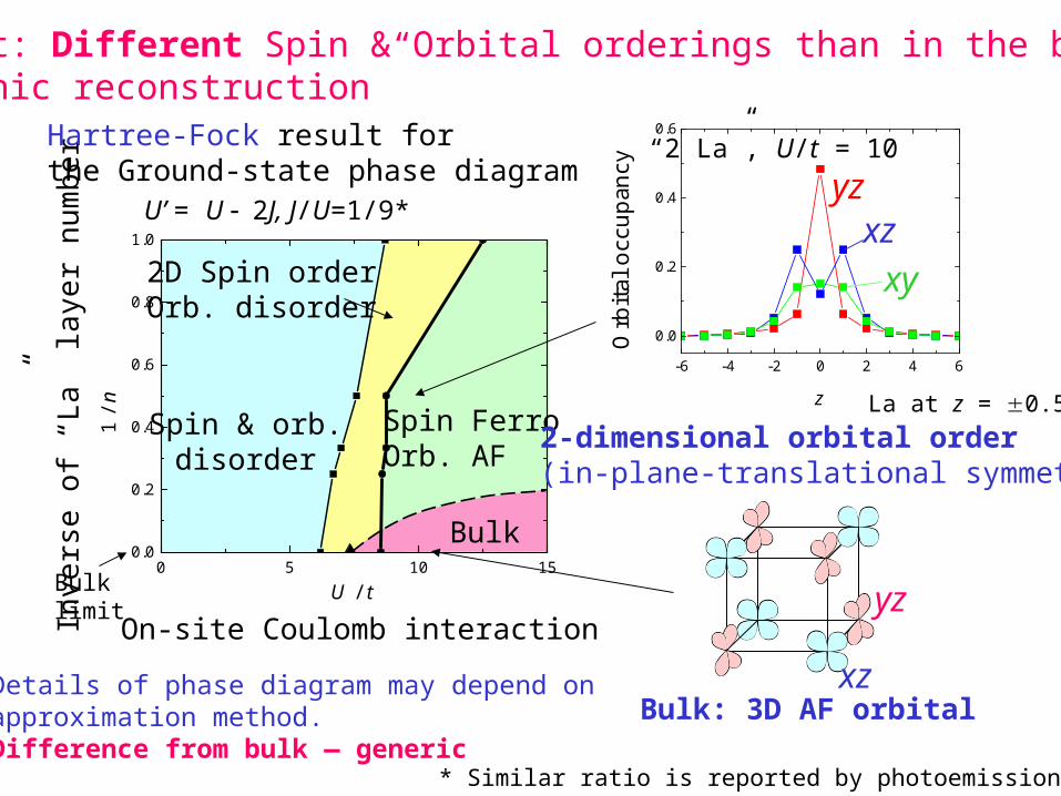
2D Spin orderOrb. disorder
Spin FerroOrb. AF
Spin & orb.disorder
Bulk0 5 10 15
0.0
0.2
0.4
0.6
0.8
1.0
1 / n
U / t
Inve
rse
of “
La”
laye
r nu
mbe
r
Bulk limit
On-site Coulomb interaction
Hartree-Fock result for the Ground-state phase diagram
Key point: Different Spin & Orbital orderings than in the bulk“Electronic reconstruction”
-6 -4 -2 0 2 4 6
0.0
0.2
0.4
0.6
Orb
ital o
ccup
ancy
z
“2 La”, U/t = 10
yzxz
xy
2-dimensional orbital order(in-plane-translational symmetry)
Bulk: 3D AF orbital
yz
xz
La at z = 0.5
Details of phase diagram may depend on approximation method. Difference from bulk — generic
U’ = U 2J, J/U=1/9*
* Similar ratio is reported by photoemission
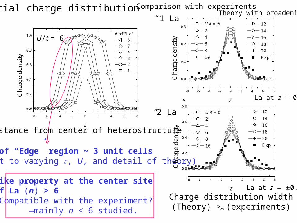
Spatial charge distribution
-8 -6 -4 -2 0 2 4 6 8
0.0
0.2
0.4
0.6
0.8
1.0 # of "La" 8 7 4 3 2 1
C
harg
e de
nsity
z
Width of “Edge” region ~ 3 unit cells(robust to varying , U, and detail of theory)
Bulk like property at the center site at # of La (n) > 6
Compatible with the experiment?—mainly n < 6 studied.
U/t = 6
-8 -6 -4 -2 0 2 4 6 8
0.0
0.2
0.4
0.6
0.8
12 14 16 18 20 Exp.
U/t = 0 2 4 6 8 10
Cha
rge
dens
ity
z
-8 -6 -4 -2 0 2 4 6 8
0.0
0.1
0.2
0.3 12 14 16 18 20 Exp.
U/t = 0 2 4 6 8 10
Cha
rge
dens
ity
z
Comparison with experiments
“1 La”
“2 La”
Charge distribution width(Theory) > (experiments)
Theory with broadening
~
La at z = 0
La at z = 0.5
Distance from center of heterostructure
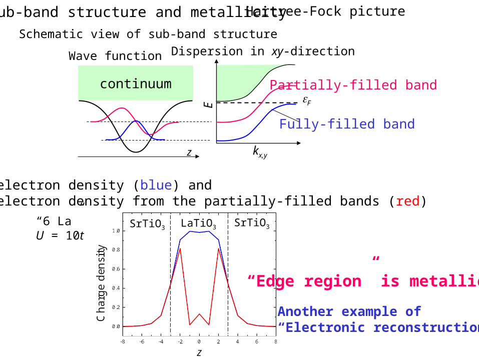
Sub-band structure and metallicity
F
Schematic view of sub-band structure
continuum
z kx,y
E
Wave function Dispersion in xy-direction
Total electron density (blue) and electron density from the partially-filled bands (red)
“6 La”U = 10t
“Edge region” is metallic!!
Fully-filled band
Partially-filled band
Hartree-Fock picture
Another example of“Electronic reconstruction”
SrTiO3SrTiO3LaTiO3
2. Beyond Hartree-Fock by Dynamical-mean-field theory (DMFT) 2.1. Metallic interface and quasiparticle 2.2. Magnetic ordering (on-going work)
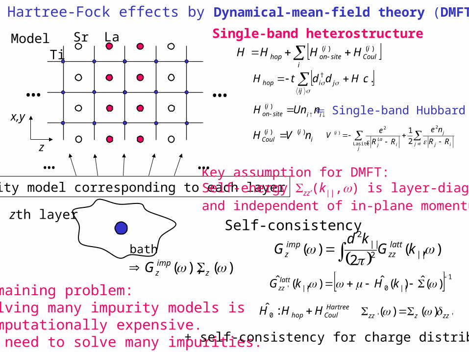
Beyond Hartree-Fock effects by Dynamical-mean-field theory (DMFT)
i
iCoul
isiteonhop HHHH )()(
ii
isiteon nUnH )( Single-band Hubbard
ij
jihop cHddtH ..†
Impurity model corresponding to each layerKey assumption for DMFT: Self-energy zz’(k||,) is layer-diagonaland independent of in-plane momentum k||
Self-consistency
)(),( zimpzG
ij ij
j
ji
Laj
i
RR
ne
RR
eV
2
siteLa
2)(
2
1i
iiCoul nVH )()(
),(2
)( ||2||
2
kGkd
G lattzz
impz
1
||0||' )(ˆ)(ˆ),(ˆ kHkG latt
zz
'' )()( zzzzz
… …
HartreeCoulhop HHH :ˆ
0
LaTi
Sr
… …
bath
zth layer
Remaining problem: Solving many impurity models is computationally expensive.We need to solve many impurities.
z
x,y
Single-band heterostructure
+ self-consistency for charge distribution
Model
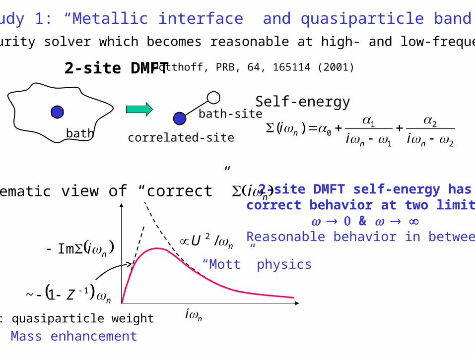
DMFT study 1: “Metallic interface” and quasiparticle band
2
2
1
10)(
nnn ii
i
2-site DMFT self-energy hascorrect behavior at two limits
& Reasonable behavior in between
Potthoff, PRB, 64, 165114 (2001)2-site DMFT
bath
bath-site
correlated-site
Self-energy
ni Im
in
nU /2
nZ 11~
“Mott” physics
Mass enhancement
Schematic view of “correct” in
Z: quasiparticle weight
We need impurity solver which becomes reasonable at high- and low-frequency regions
Strong coupling regime
0.0
0.10.0
0.10.0
0.10.0
0.10.0
0.10.0
0.10.0
0.1
-10 0 10 200.0
0.1
z = 7
z = 6
z = 5
z = 4
z = 3
z = 2
z = 1
z = 0
/t
A(z
,z;
)
0.0
0.10.0
0.1
0.0
0.1
z = 10
z = 9
z = 8
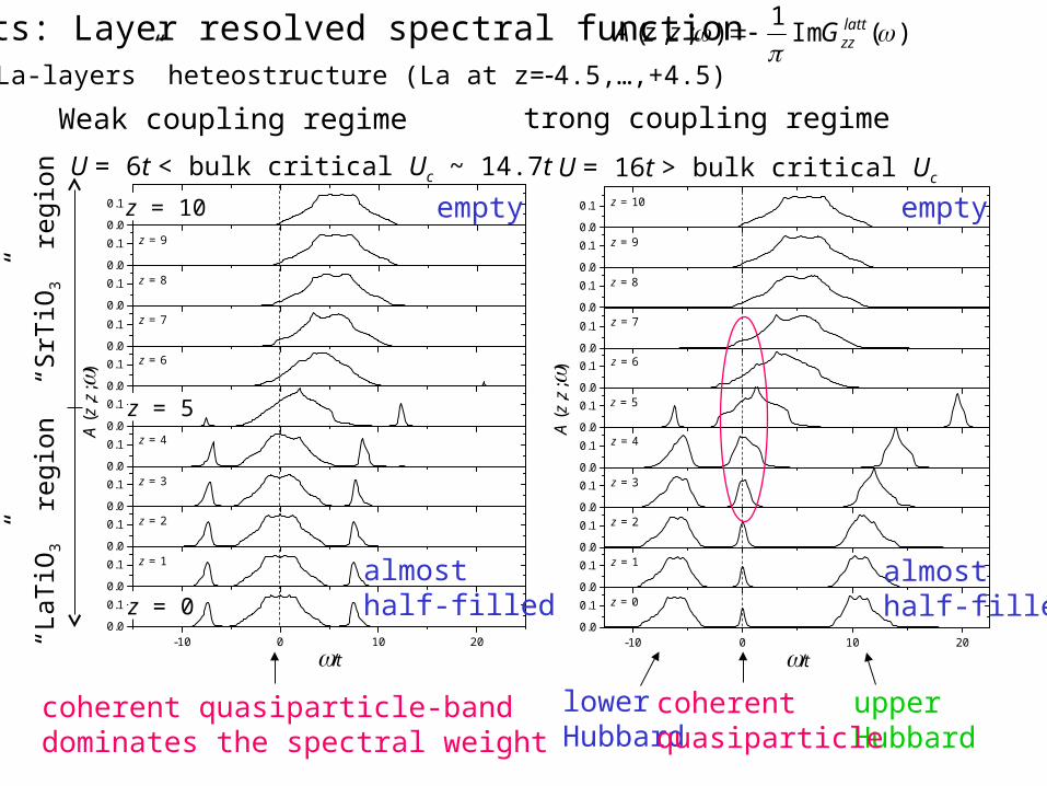
lowerHubbard
upperHubbard
coherentquasiparticle
empty
almosthalf-filled
U = 16t > bulk critical Uc
0.0
0.10.0
0.10.0
0.10.0
0.10.0
0.10.0
0.10.0
0.1
-10 0 10 200.0
0.1
z = 7
z = 6
z = 5
z = 4
z = 3
z = 2
z = 1
z = 0
/t
A(z
,z;
)
0.0
0.10.0
0.1
0.0
0.1
z = 10
z = 9
z = 8
)(Im1
);,(
lattzzGzzA
“10 La-layers” heteostructure (La at z=4.5,…,+4.5)
U = 6t < bulk critical Uc ~ 14.7t
coherent quasiparticle-banddominates the spectral weight
empty
almosthalf-filled
Results: Layer resolved spectral function
z = 10
“LaT
iO3”
reg
ion
“SrT
iO3”
reg
ion
Weak coupling regime
z = 0
z = 5
-10 -8 -6 -4 -2 0 2 4 6 8 100.0
0.2
0.4
0.6
0.8
1.0 ntot by HF
ntot
ncoh
ntot , n
coh
z
-10 0 10
/t
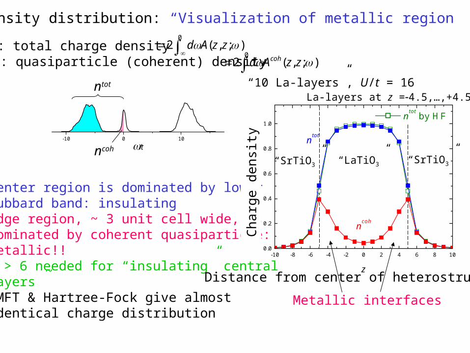
Charge density distribution: “Visualization of metallic region”
ntot: total charge densityncoh: quasiparticle (coherent) density
Center region is dominated by lower Hubbard band: insulatingEdge region, ~ 3 unit cell wide, isdominated by coherent quasiparticle:Metallic!!n > 6 needed for “insulating” centralLayersDMFT & Hartree-Fock give almostidentical charge distribution
0);,(2 zzAd
0
);,(2 zzAd coh
“10 La-layers”, U/t = 16
~
ntot
ncoh
Distance from center of heterostructure
Metallic interfaces
La-layers at z =4.5,…,+4.5
Cha
rge
dens
ity
“SrTiO3” “SrTiO3”“LaTiO3”
DMFT study 2: Magnetic ordering
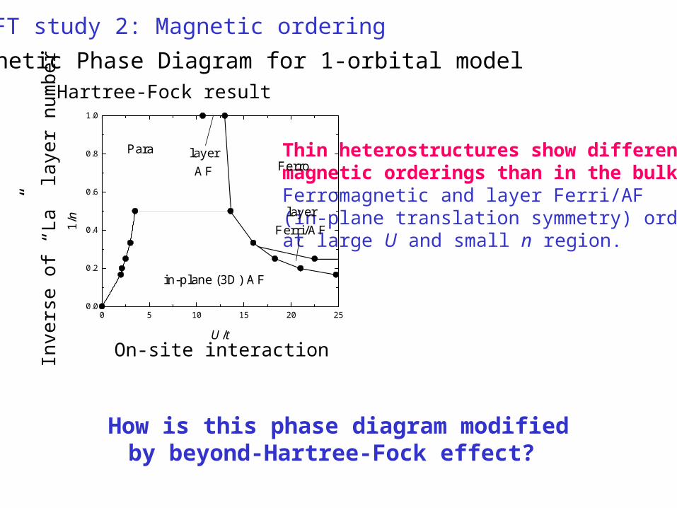
Magnetic Phase Diagram for 1-orbital modelHartree-Fock result
Inve
rse
of “
La”
laye
r nu
mbe
r
Thin heterostructures show differentmagnetic orderings than in the bulk.Ferromagnetic and layer Ferri/AF (in-plane translation symmetry) orderingsat large U and small n region.
How is this phase diagram modifiedby beyond-Hartree-Fock effect?
On-site interaction
0 5 10 15 20 250.0
0.2
0.4
0.6
0.8
1.0
layerFerri/AF
Ferro
in-plane (3D) AF
layerAF
Para
1/n
U/t
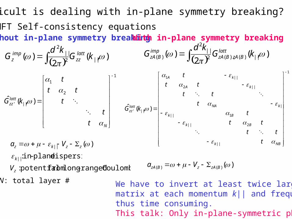
How difficult is dealing with in-plane symmetry breaking?
DMFT Self-consistency equations
),(2
)( ||2||
2
kGkd
G lattzz
impz
1
2
1
||' ),(ˆ
N
lattzz
t
t
t
tt
t
kG
)(|| zzkz Va
N: total layer #
Without in-plane symmetry breaking
),(2
)( ||)(),(2||
2
)(
kGkd
G lattBzABzA
impBzA
1
||
2||
1||
||
||2
||1
||' ),(ˆ
NBk
Bk
Bk
kNA
kA
kA
lattzz
t
tt
tt
t
t
tt
tt
t
kG
With in-plane symmetry breaking
)()()( BzAzBzA Va dispersion plane-in:||k
Coulomb ranged-long from potential:zV
We have to invert at least twice larger matrix at each momentum k|| and frequency,thus time consuming. This talk: Only in-plane-symmetric phases
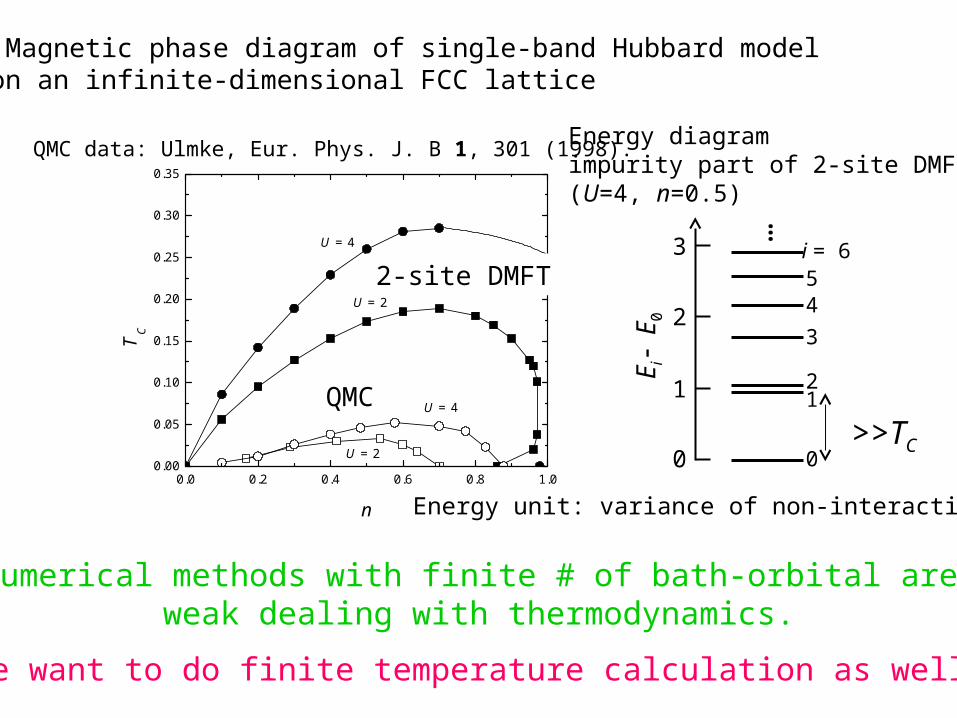
Numerical methods with finite # of bath-orbital are weak dealing with thermodynamics.
We want to do finite temperature calculation as well.
0.0 0.2 0.4 0.6 0.8 1.00.00
0.05
0.10
0.15
0.20
0.25
0.30
0.35
QMC
2-site DMFT
U = 2
U = 4
U = 2
U = 4
T C
n
Trial: Magnetic phase diagram of single-band Hubbard modelon an infinite-dimensional FCC lattice
Energy diagramimpurity part of 2-site DMFT(U=4, n=0.5)
>>TC
Energy unit: variance of non-interacting DOS
QMC data: Ulmke, Eur. Phys. J. B 1, 301 (1998).
QMC
2-site DMFT
Ei
E0
3
2
1
0 0
12
3
45i = 6
…
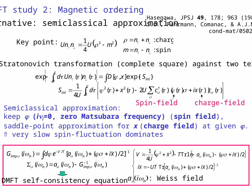
DMFT study 2: Magnetic ordering
Alternative: semiclassical approximationHasegawa, JPSJ 49, 178; 963 (1980).S.O., Fuhrmann, Comanac, & A.J.M.,
cond-mat/0502067.
22
4
1mUnUn
spin:
charge:
nnm
nnKey point:
Hubbard-Stratonovich transformation (complete square) against two terms:
}exp{],[)()(exp0 intSxDnUnd
0
†22 )()}()(){(2)()(4
1cixcUxd
USint
Semiclassical approximation: keep (il=0, zero Matsubara frequency) (spin field), saddle-point approximation for x (charge field) at given . very slow spin-fluctuation dominates
1/ ]2/)()([)( xiiaediG nTV
nimp
12/)()(Tr xiiaUTxi n
2/)()(lnTr4
1 22 xiiaTxU
V n
)()()( 1nimpnn iGiai
ain: Weiss fieldDMFT self-consistency equation
Spin-field charge-field
0 5 10 15 200.0
0.2
0.4
0.6
0.8
1.0
Semiclassical QMC Hartree-Fock Strong coupling
T/t
U/t
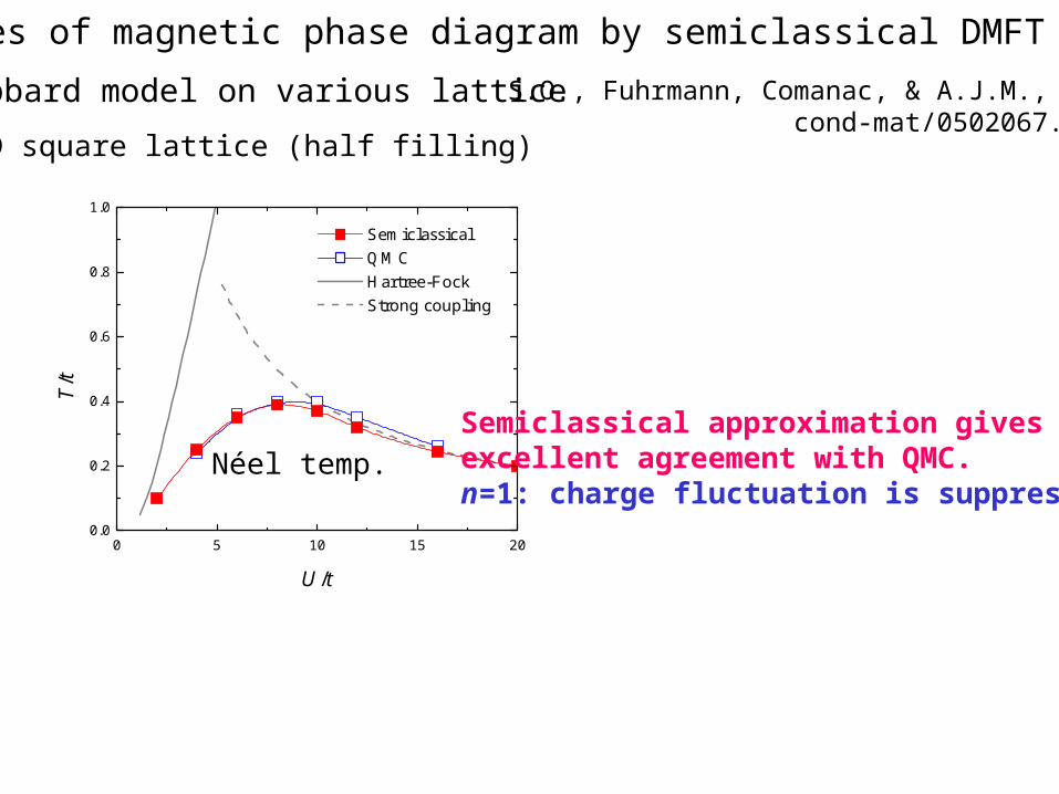
Examples of magnetic phase diagram by semiclassical DMFT
2D square lattice (half filling)
Hubbard model on various lattice S.O., Fuhrmann, Comanac, & A.J.M., cond-mat/0502067.
Néel temp.
Semiclassical approximation gives excellent agreement with QMC.n=1: charge fluctuation is suppressed
0.0 0.2 0.4 0.6 0.8 1.00.00
0.05
0.10
0.15HF (101)
TC
QMC T
C
TN
Semiclassical T
C
TN
T
n
0.90 0.95 1.000.00
0.05
0.10
T
n
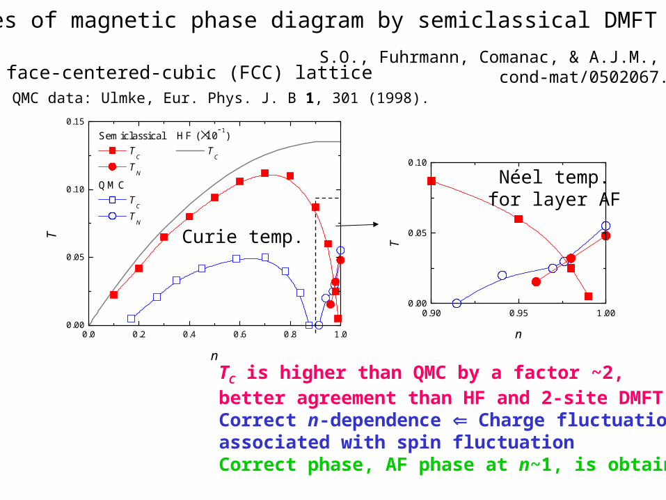
3D face-centered-cubic (FCC) lattice
Curie temp.
QMC data: Ulmke, Eur. Phys. J. B 1, 301 (1998).
Néel temp.for layer AF
Examples of magnetic phase diagram by semiclassical DMFT
S.O., Fuhrmann, Comanac, & A.J.M., cond-mat/0502067.
TC is higher than QMC by a factor ~2, better agreement than HF and 2-site DMFT.Correct n-dependence Charge fluctuationassociated with spin fluctuationCorrect phase, AF phase at n~1, is obtained.
0 5 10 15 20 250.0
0.2
0.4
0.6
0.8
1.0
layerFerri/AF
Ferro
in-plane (3D) AF
layerAF
Para
1/n
U/t
Hartree-Fock resultMagnetic Phase Diagram
Inve
rse
of “
La”
-lay
er n
umbe
r
On-site interaction
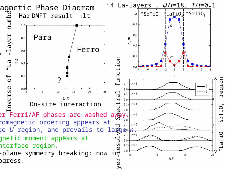
Magnetic moment appears at “interface region.”In-plane symmetry breaking: now in progress.
0.0
0.10.0
0.10.0
0.10.0
0.10.0
0.10.0
0.1
-10 0 10 200.0
0.1 z = 0
/t
z = 1
z = 2
z = 3
z = 4
z = 5
z = 6
Lay
er-r
esol
ved
Spe
ctra
l fun
ctio
n
“LaT
iO3”
“SrT
iO3”
reg
ion
-8 -6 -4 -2 0 2 4 6 80.0
0.2
0.4
0.6
0.8
1.0
m
n
n, m
z
“4 La-layers”, U/t=18, T/t=0.1“SrTiO3” “SrTiO3”“LaTiO3”
Para
Ferro
DMFT result
?
Layer Ferri/AF phases are washed away. Ferromagnetic ordering appears at large U region, and prevails to large n.
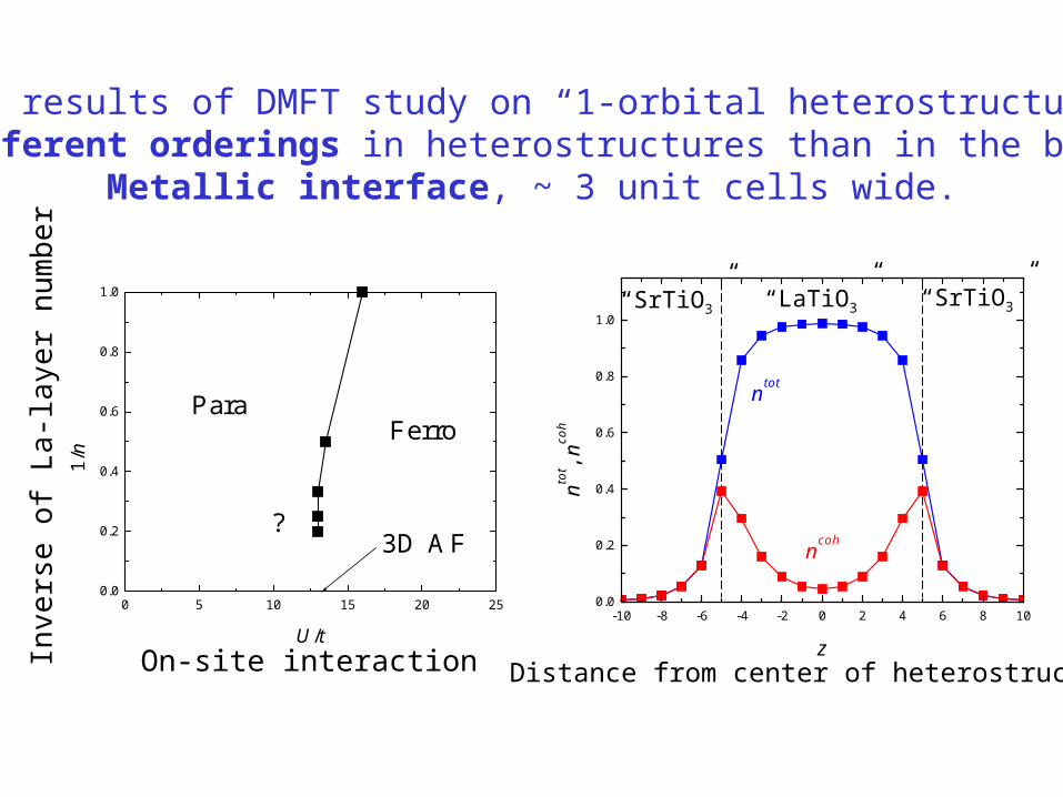
0 5 10 15 20 250.0
0.2
0.4
0.6
0.8
1.0
?3D AF
FerroPara
1/n
U/t-10 -8 -6 -4 -2 0 2 4 6 8 10
0.0
0.2
0.4
0.6
0.8
1.0
ntot
ncoh
ntot , n
coh
z
Inve
rse
of L
a-la
yer
num
ber
On-site interaction Distance from center of heterostructure
Main results of DMFT study on “1-orbital heterostructure”:Different orderings in heterostructures than in the bulk
Metallic interface, ~ 3 unit cells wide.
“SrTiO3” “SrTiO3”“LaTiO3”
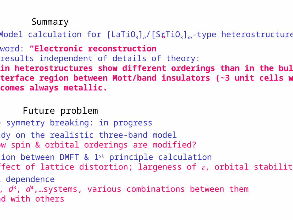
Future problemIn-plane symmetry breaking: in progress
DMFT study on the realistic three-band model How spin & orbital orderings are modified?
Combination between DMFT & 1st principle calculation Effect of lattice distortion; largeness of , orbital stability
Material dependence d2, d3, d4,…systems, various combinations between them and with others
SummaryModel calculation for [LaTiO3]n/[SrTiO3]m-type heterostructure
Key word: “Electronic reconstruction”Key results independent of details of theory: Thin heterostructures show different orderings than in the bulk. Interface region between Mott/band insulators (~3 unit cells wide) becomes always metallic.