Satellite Dish Specifications - Rover Pipeline Facts Dish Specifications February 2015 ....
10
ROVER PIPELINE PROJECT Resource Report 1 – Project Description APPENDIX 1D Satellite Dish Specifications February 2015
Transcript of Satellite Dish Specifications - Rover Pipeline Facts Dish Specifications February 2015 ....
ROVER PIPELINE PROJECT Resource Report 1 – Project Description
APPENDIX 1D
Satellite Dish Specifications
February 2015

Receive/TransmitSeries 1134
OptionFeed Horn w/ OMT &Transmit Reject Filter
Back View1.2M Rx/Tx
1.2M KU-BAND
RX/TX
SERIES
1134
Key Features· IntelSat approval number
IAO45A00
· AsiaSat approved
· EutelSat VSAT typeapproval
· ETSI Certification
· New optics for low cross-polcompliance
· Precision compressionmolded offset reflector
· Low cost shipping & easylocal handling
· Simplified one-maninstallation - less than onehour assembly
Prodelin Corporation is theworld’s largest manufacturer ofRx/Tx VSAT antennas. We havethe broadest product line in theindustry including Receive Only,Rx/Tx and Rural Telephonyantenna systems. Prodelin offersnineteen antenna sizes, 47cm to4.5M. Prodelin is the leader inobtaining type certifications andapprovals for Intelsat, AsiaSatand Eutelsat. Prodelin antennasprovide the best quality in themarket due to the sophisticated,precision SMC compressionmolding process technology.Prodelin provides the best valueantenna solution to the marketwith competitive prices, thehighest quality products andsuperb engineering support.Prodelin is ISO registered,KEMA # 70022.01. Prodelin -The Market Leader in VSATAntennas.
5002-354 (5-2000)
© Copyright 2000 Prodelin, a TriPoint Global Company.All product specifications subject to change without notice.The Prodelin logo is a trademark of TriPoint Global.
1.2M KU-BAND
RX/TX
SERIES
1134
Electrical
Environmental Performance
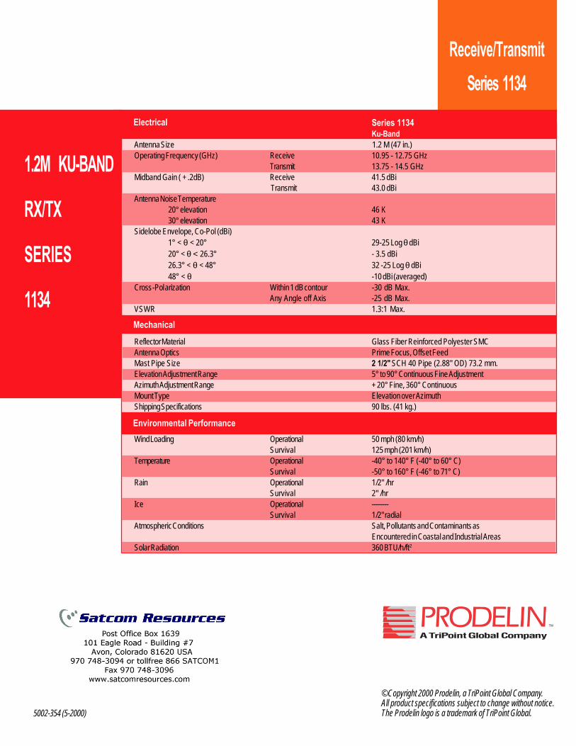
Receive/TransmitSeries 1134
Mechanical
Series 1134Ku-Band
Antenna Size 1.2 M (47 in.)Operating Frequency (GHz) Receive 10.95 - 12.75 GHz
Transmit 13.75 - 14.5 GHzMidband Gain ( + .2dB) Receive 41.5 dBi
Transmit 43.0 dBiAntenna Noise Temperature
20° elevation 46 K30° elevation 43 K
Sidelobe Envelope, Co-Pol (dBi)1° < θ < 20° 29-25 Log θ dBi20° < θ < 26.3° - 3.5 dBi26.3° < θ < 48° 32 -25 Log θ dBi48° < θ -10 dBi (averaged)
Cross-Polarization Within 1 dB contour -30 dB Max.Any Angle off Axis -25 dB Max.
VSWR 1.3:1 Max.
Reflector Material Glass Fiber Reinforced Polyester SMCAntenna Optics Prime Focus, Offset FeedMast Pipe Size 2 1/2" SCH 40 Pipe (2.88" OD) 73.2 mm.Elevation Adjustment Range 5° to 90° Continuous Fine AdjustmentAzimuth Adjustment Range + 20° Fine, 360° ContinuousMount Type Elevation over AzimuthShipping Specifications 90 lbs. (41 kg.)
Wind Loading Operational 50 mph (80 km/h)Survival 125 mph (201 km/h)
Temperature Operational -40° to 140° F (-40° to 60° C)Survival -50° to 160° F (-46° to 71° C)
Rain Operational 1/2" /hrSurvival 2" /hr
Ice Operational --------Survival 1/2" radial
Atmospheric Conditions Salt, Pollutants and Contaminants asEncountered in Coastal and Industrial Areas
Solar Radiation 360 BTU/h/ft2

Printed in the U.S.A. Sky Global 1315 Industrial Park Drive Smithfield, NC 27577
Telephone: +1-919-934-9711
Internet: www.skywareglobal.com 04/11 8001014-01S Rev D EC-01063
Important: Perform these steps prior to completing feed leg installation (page 4 of 8001014-01)
1) Install Left Hand and Right Hand rear braces between the az/el cap mount and the sides of the reflector as shown. Secure the slotted end of each brace to the az/el mount with M6 x 16 mm screw, star washer, flat washer, lock washer, and nut. With this hardware loose, temporarily secure the reflector end of brace to the rim of the dish with M6 x 20 mm screw and nut. Tighten the reflector end hardware
(snug tight only), and then tighten the az/el hardware fully at this time.
2) Proceed to feed leg installation as described in the main manual. Install the side legs first, by removing the nut and attaching the leg and securing with lock washer and nut.
Reflector
Right Rear Brace
M6 Flat M6 Lock Washer Washer (2 Places) (2 Place4-- M6 Hex Nut
(2 Places)
Bottom Feed Leg
Side Feed Leg
N — Right Rear Brace
M6 x 20 mm Screw (2 Places)
Left Rear Brace Az/E1 Cap Mount
M6 Hex Nut (2 Places)
M6 Lock Washer (2 Places)
Left Rear Brace
M6 Star Washer (2 Places) M6 x 16 mm
Hex Bolt (2 Places)
Side Feed Leg
Assembly Instructions
1.2 m Rear Brace Installation for Type 125 Antenna Systems
This instruction sheet supplements the feed leg assembly notes that are in Manual 8001014-01
8001014-01S
Deep Frost Line Foundations
Bubble I 91.4 cm
t max.
Level (36") 182.9 cm
(72" NOTE:
be increased to frost 127 cm (50") may
line. Concrete and length of rebar will
increase accordingly.
#3 rebar x .46 m (18") Insert through
hole in tube and center.
#3 rebar x .6 m (241 at 60- apart (See note)
25 mm to 51 mm (1" to 2") slope For water run-off
Grade
Minimum (2 Below 51 mm
") Diameter Frost Line
Ground Pole Must Be Vertical in All Directions
at Top
73 cm or 76 cm -Is- -4- (2.88" or 3.00" O.D.)
Bottom View
t 91.4 cm max.
182.9 cm (361
(721
73 cm or 7.6 cm (2.88" or 3.00" O.D.)
#3 rebar Below
of pier. Insert through Diameter Frost Line hole in tube and center.
x diameter Milum
to 51 mm (1" to 2") slope
for water run-off
I Grade
EXPOSURE B
EXPOSURE C
DIM D CONC VOL cm (in) m3 (ft3 )
D CONC VOL
cm (in) m3 (PI GROUND
POLE
Fcl :k•111g VAIN k
Pier Foundations
Pier Foundations
EXPOSURE B EXPOSURE C
WIND VEL km/h (mph)
DIME D
cm (in)
CONC VOL
m3 (ft3 )
DIM D cm (in)
CONC VOL m 3 (ft3 )
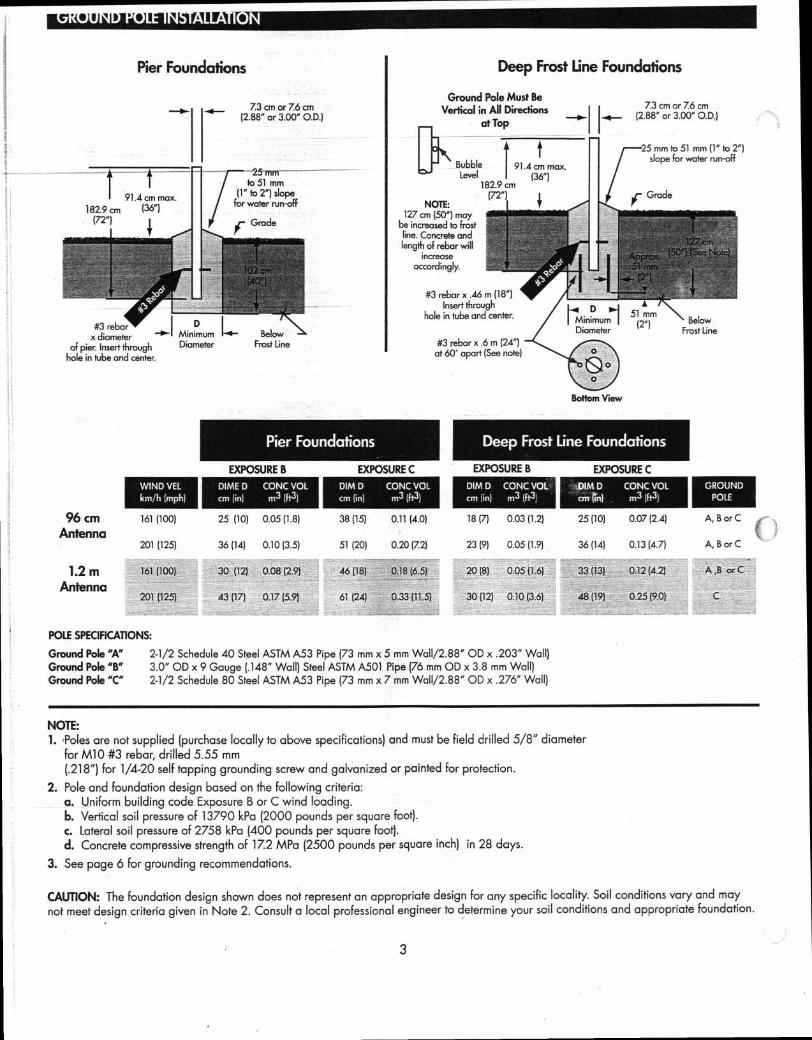
96 cm 161 (100) 25 (10) 0.05 (1.8) 38 (15) 0.11 (4.0)
Antenna 201 (125) 36 (14) 0.10 (3.5) 51 (20) 0.20 (72)
1.2 m 161 (100) 30 (12) 0.08 (2.9) 46 (18) 0.18 (6.5)
Antenna 201 (125) 43 (17) 0.17 (5.9) 61 (24) 0.33 (11.5)
Deep Frost Line Foundations
18(7) 0.03(1.2)
25 (10)
0.07 (2.4)
23 (9) 0.05 (1.9)
36 (14)
0.13 (4.7)
20 (8) 0.05 (1.6)
33 (13)
0.12 (4.2)
30 (12) 0.10 (3.6)
48 (19)
0.25 (9.0)
A, B or C
A, B or C
A ,B orC
POLE SPECIFICATIONS:
Ground Pole "A"
2-1/2 Schedule 40 Steel ASTM A53 Pipe (73 mm x 5 mm Wall/2.88" OD x .203" Wall) Ground Pole "B"
3.0" OD x 9 Gauge (.148" Wall) Steel ASTM A501 Pipe (76 mm OD x 3.8 mm Wall) Ground Pole "C"
2-1/2 Schedule 80 Steel ASTM A53 Pipe (73 mm x 7 mm Wall/2.88" OD x .276" Wall)
NOTE: 1. 'Poles are not supplied (purchase locally to above specifications) and must be field drilled 5/8" diameter
for M10 #3 rebar, drilled 5.55 mm (.218") for 1/4-20 self tapping grounding screw and galvanized or painted for protection.
2. Pole and foundation design based on the following criteria: a. Uniform building code Exposure B or C wind loading. b. Vertical soil pressure of 13790 kPa (2000 pounds per square foot). c. Lateral soil pressure of 2758 kPa (400 pounds per square foot). d. Concrete compressive strength of 17.2 MPa (2500 pounds per square inch) in 28 days.
3. See page 6 for grounding recommendations.
CAUTION: The foundation design shown does not represent an appropriate design for any specific locality. Soil conditions vary and may not meet design criteria given in Note 2. Consult a local professional engineer to determine your soil conditions and appropriate foundation.
3
Bottom View
Square Nut (Factory Preset)
Azimuth Azimuth Locking Locking Hex Nut Hex Nut
Open Side of Pipe Clamp
Open Side of Inner Sleeve
Flat Washer Flat Washer
Lock Washer M6 x 16 mm Hex Bolt
M6 x 16 mm Hex Bolt
Lock Washer
Hex Nut Lock Washer
Hex Bolt
Hex Nut
o
M6 x 16 mm
4%141&O
Junction Block
Flat Washer
Bottom Feed Leg
Lock Washer 4
M6 x 16 mm Hex Bolt
Hex Nut
Lock Washer
ASSEMBLY AND INSTALLATION
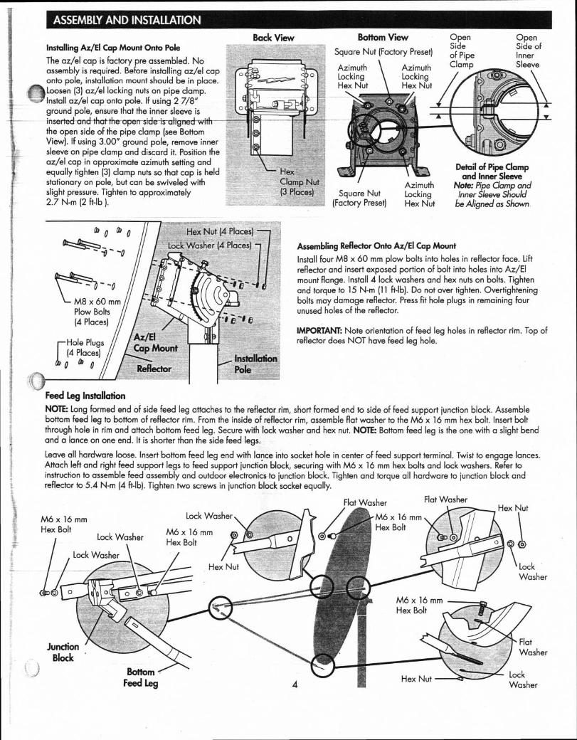
Back View Installing Az/EI Cap Mount Onto Pole
The az/el cap is factory pre assembled. No assembly is required. Before installing az/el cap onto pole, installation mount should be in place. Loosen (3) az/el locking nuts on pipe clamp.
fl Install az/el cap onto pole. If using 2 7/8" ground pole, ensure that the inner sleeve is inserted and that the open side is aligned with -- -- the open side of the pipe clamp (see Bottom View). If using 3.00" ground pole, remove inner sleeve on pipe clamp and discard it. Position the az/el cap in approximate azimuth setting and equally tighten (3) clamp nuts so that cap is held stationary on pole, but can be swiveled with slight pressure. Tighten to approximately 2.7 N-m (2 ft-lb ).
Hex Clamp Nut (3 Places) Square Nut
(Factory Preset)
Azimuth Locking Hex Nut
Detail of Pipe Clamp and Inner Sleeve
Note: Pipe Clamp and Inner Sleeve Should
be Aligned as Shown
—Hole Plugs
0 ° 0
M8 x 60 mm Plow Bolts (4 Places)
Az/E)Cap Mount (4 Places)
Installation Reflector
lk•
a me)
Pole
(19 a° 0 0 Hex Nut (4 Places)
Lock Washer (4 Places) Assembling Reflector Onto Az/EI Cap Mount
Install four M8 x 60 mm plow bolts into holes in reflector face. Lift reflector and insert exposed portion of bolt into holes into Az/EI mount flange. Install 4 lock washers and hex nuts on bolts. Tighten and torque to 15 N-m (11 ft-lb). Do not over tighten. Overtightening bolts may damage reflector. Press fit hole plugs in remaining four unused holes of the reflector.
IMPORTANT: Note orientation of feed leg holes in reflector rim. Top of reflector does NOT have feed leg hole.
Feed Leg Installation
NOTE: long formed end of side feed leg attaches to the reflector rim, short formed end to side of feed support junction block. Assemble bottom feed leg to bottom of reflector rim. From the inside of reflector rim, assemble flat washer to the M6 x 16 mm hex bolt. Insert bolt through hole in rim and attach bottom feed leg. Secure with lock washer and hex nut. NOTE: Bottom feed leg is the one with a slight bend and a lance on one end. It is shorter than the side feed legs.
Leave all hardware loose. Insert bottom feed leg end with lance into socket hole in center of feed support terminal. Twist to engage lances. Attach left and right feed support legs to feed support junction block, securing with M6 x 16 mm hex bolts and lock washers. Refer to instruction to assemble feed assembly and outdoor electronics to junction block. Tighten and torque all hardware to junction block and reflector to 5.4 N-m (4 ft-lb). Tighten two screws in junction block socket equally.
Clamp Bolt
Alignment Mark
Elevation Adjustment Bolt
Elevation Locking Bolts (Both Sides)
Elevation Alignment Arrow
Compass
• Rotate Antenna On Ground Tube
Azimuth
Elevation Fine Tuning
Do
Azimuth Fine Tuning
5
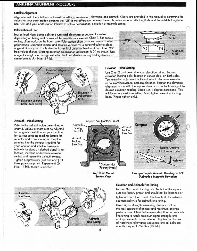
TENNA ALIGNMENT PROCEDURE
Satellite Alignment
Alignment with the satellite is obtained by setting polarization, elevation, and azimuth. Charts are provided in this manual to determine the values for your earth station antenna site. "AL" is the difference between the earth station antenna site longitude and the satellite longitude. Use "AL" and your earth station latitude to obtain polarization, elevation or azimuth setting.
Polarization of Feed
Loosen feed Horn clamp bolts and turn feed clockwise or counterclockwise, depending on being east or west of the satellite as shown on Chart 1. For coarse setting, align marks-on the horn scale. Polarization chart assumes antenna system polarization is transmit vertical and satellite vertical Pol is perpendicular to plane of geostationary arc. For horizontal transmit of antenna, feed must be rotated 90° from values shown. (Starting point for polarization adjustment is 0°, as shown. Use a signal strength measuring device for final polarization setting and tighten horn clamp bolts to 5.4 N-m (4 ft-lb).
Azimuth Locking Hex Nut
Azimuth Locking Hex Nut
Elevation - Initial Setting
Use Chart 2 and determine your elevation setting. Loosen elevation locking bolts, located in curved slots, on both sides. Turn elevation adjustment bolt clockwise to decrease elevation or counterclockwise to increase elevation. Position the elevation alignment arrow with the appropriate mark on the housing at the desired elevation reading. Scale is in 1 degree increments. This will be an approximate setting. Snug tighten elevation locking bolts. (Finger tighten only).
Azimuth - Initial Setting
Refer to the azimuth value determined on chart 3. Values in chart must be adjusted for magnetic deviation for your location for correct compass reading. Rotate the reflector and az/el mount, on the pipe, pointing it to the compass reading for your location and satellite. Sweep in azimuth for signal. If desired signal is not located, increase or decrease elevation setting and repeat the azimuth sweep. Tighten progressively (1/8 turn each) all three pipe clamp nuts. Repeat until 24 N-m (18 ft-lb) torque is reached.
Square Nut (Factory Preset)
Ll Azimuth \`-./ Locking
Hex Nut
Square Nut (Factory Preset)
Az/EI Cap Mount Bottom View
Example Depicts Azimuth Heading To 171 . (Azimuth ± Magnetic Deviation)
Elevation and Azimuth Fine Tuning
Loosen (3) azimuth locking nuts. Note that the square nuts are factory preset, and should not be loosened or
tightened. Turn the azimuth fine tune bolt clockwise or counterclockwise for azimuth fine tuning.
Use a signal strength measuring device to obtain the most accurate alignment and maximum antenna performance. Alternate between elevation and azimuth fine tuning to reach maximum signal strength, until no improvement can be detected. Tighten and torque all hardware, alternating sequence, until all bolts are equally torqued to 24 N-m (18 ft-lb).
Tooth Washer
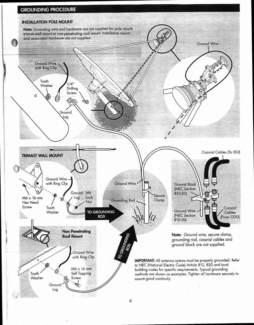
GROUNDING PROCEDURE
INSTALLATION POLE MOUNT
Note: Grounding wire and hardware are not supplied for pole mount,
trimast wall mount or non penetrating roof mount. Installation mount
and associated hardware are not supplied.
Ground Wire
Ground Wire with Ring Clip
Tooth Washer 1/4"
Drilling Screw
Ground Lug
Coaxial Cables (To IDU) TRIMAST WALL MOUNT
Ground Wire with Ring Clip
Ground M6
M6 x 16 mm
.111,
Hex Head
/ Lug Lock Nut
Screw Tooth Washer
Non Penetrating Roof Mount
Grounding Rod
Ground Wire
Secure Clamp
Ground Block (NEC Section
810-20)
Ground Wire (NEC Section
810-20)
Coaxial Cables
(From ODU)
Note: Ground wire, secure clamp,
grounding rod, coaxial cables and
ground block are not supplied.
iet
TO GROUNDING ROD
Ground Wire with Ring Clip
M6 x 16 mm Self Tapping Screw
IMPORTANT: All antenna sytems must be properly grounded. Refer
to NEC (National Electric Code) Article 810, 820 and local
building codes for specific requirements. Typical grounding
methods are shown as examples. Tighten all hardware securely to
assure good continuity.
Ground Lug
6
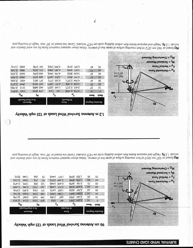
1016'0 g8gZ (811) LPZ (Z92-) O6£'£' (gLg) 16Z'Z LS OZ
be esez (ze) cte (986.1 1807- (9891 190'E 11 09
Icss'd SSVE loo) soy 1EV6-1 S61'17 - IZZ8) 9g9'E 19 OS
(oz6'z) V96E (LSE) V8V (6431 zie'c - (EV6) g61‘17 19 OV
(9ZE'd LOSI izs (ILL-) e91'e- (110'1) 179L'17 LV oc (u9'e) 696V 47914 6Z9 (zotd asz's LE 7 108L'El Sttc 18814 Z99 etq' (ztti) cir's zz 01
(166T) 1017g (009) 819 (cc-) 95'1 - lgsz'il 911'g II 0
ow Ai HA
UMG9 .42aW
(sounod-booj) w-N
quawow
(sPunod) N 03.110j
saal6a0 uouonaig
ivawow 6u!tunpano = OW
ivawow puo!sioi = lW
ODJOd 11339.13A = AA
01104 INUOZIJOH = H4
1/I Hi
dty
(1t6) (17 g) EL (EVV-) 1662) NCI. co OZ
(9ZZ'L) 099'1 (OL) co (ELS-) 617g'Z- (86E) OLL'l S8 09
6661 (06) ZZL scv'z- (8114 9Z i'z SL OS
(689'1) 98tZ (L01) grL leop-) siz'z- len) ser' 99 OV
(916' 1) Zog'Z (9z ILL lcii7-1 as' (z69) L9L'L 917 OE
(91. rz) E98'L 881 6E-1 98Z'L - 1189) 9g0'E SE OZ
alit (Ivi) 661 10g1 - 1 L99- (101) sr Ce gZ 01
/711'E foci) coz (0Z-) 68- (LPL) ezeT SI 0 ow lw Ai Hi Woos ' 1PoW
(spunod--4004) W-N
(sPunoci) N
sivawow
alloj SaaJ6a0.U01.10Aal3
4uaLuow 6u!turipano = OW
WOWOW IOW:4510j = 101 = A 03J0d 10D9 .10A — A
apioA iNuozuoii = HA (u! 6 9E) ww 106
L
4sod 6uyunow Jo ig6!ag •xow „9E uo pasog au!! Japap papnpu! ION ain apoo 6u!pfinq wiopun way siopoj ainsodxa puo 4y6!aj_j c• apnpu! puo uoyDaiip puinn (uo Jo} sapioj wnwpcow pasaida, umoys sanion •uuatuo jo au!! Ja4uaD jo apojins 6ugunow way (u! jzE) ww gpa uo paspq Ow
kipoiaA Lidw SZL 40 spool puvAIDNAins ouualuy W Z'L
asod 6uyunow jo 4y6py .xow „92 uo pasoci au!! Ja4uaD papnpu! ION aio apop 6u!pfinci uuopun way vapoj ainsodxa puo .416taH Si g• apnpu!
pun uotpaqp puim (uo ioj saaloj wnw!xow ivasaidad umoys gen/DA Duuquo jo aull Ja4uaD jo apojins. 6ullunow wolf (Li! 6.90 ww ZC6 uo 13°g°cl OW
44P° 19A tidw SZL 40 spool pum impuns ouuatuy LLD 96
CIVO1 GNIM 1VAIAZIfIS
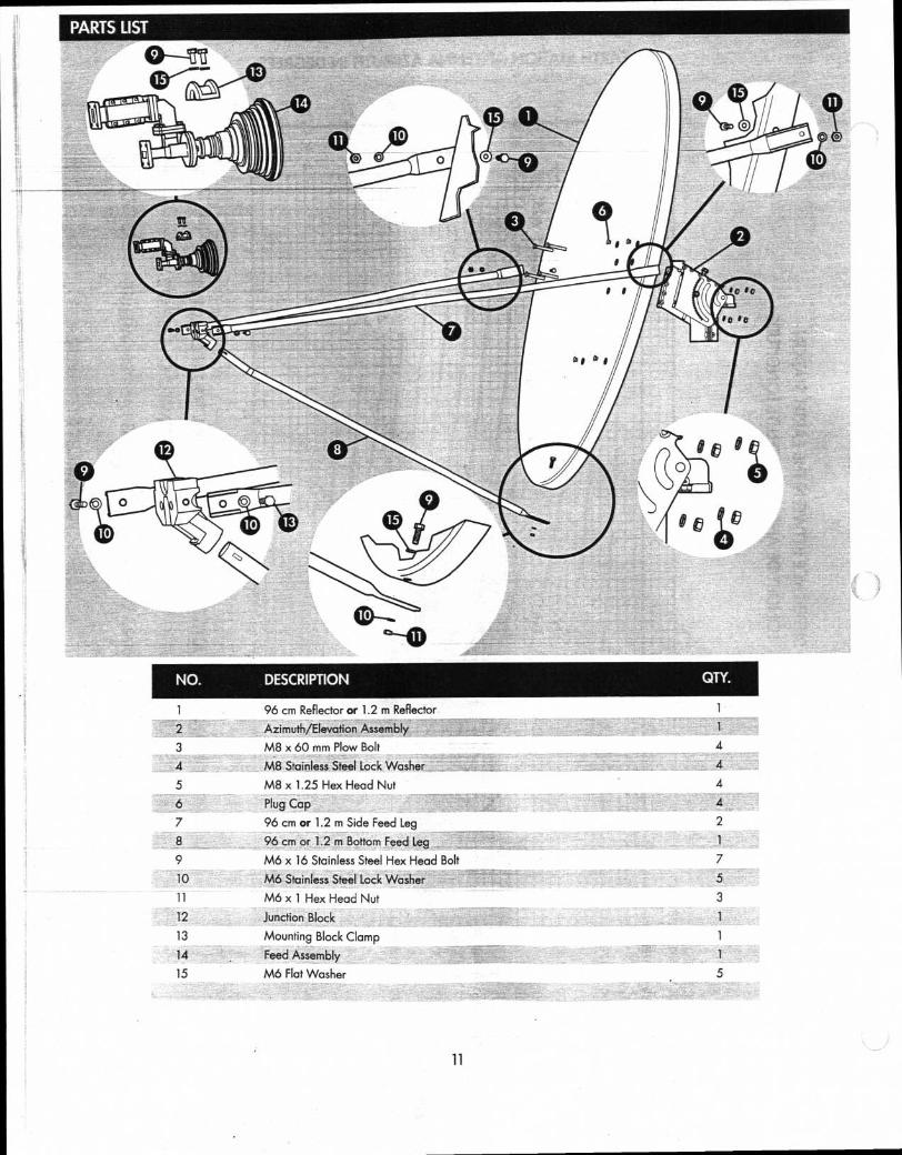
PARTS UST
NO. DESCRIPTION
QTY.
96 cm Reflector or 1.2 m Reflector
Azimuth/Elevation Assembly
M8 x 60 mm Plow Bolt
Z M8 Stainless Steel Lock Washer -4.r7"saVglIZ__0:-....-,:=,—,r;
M8 x 1.25 Hex Head Nut
Plug Cap
96 cm or 1.2 m Side Feed Leg
96 cm or 1.2 m Bottom Feed leg
M6 x 16 Stainless Steel Hex Head Bolt
M6 Stainless Steel Lock Washer
M6 x 1 Hex Head Nut
Junction Block
Mounting Block Clamp
Feed Assembly
M6 Flat Washer
2
3
4
5
7
8
9
10
11
12
13
14
15
4 4
4 4
2
7
5
3
5
11