Satellite Data Link Validation Test Plan · Supplementary Notes 16. ... Aircraft equipped with...
19
AD-A242 892 #7f T f 9. Satellite Data Link Validation Test Plan Hilda M. DiMeo * September 1991 DOT/FAA/CT-TN91/6 This document is available to the U.S. public through the National Technical Information Service, Springfield, Virginia 22161. hUS Department of Tronsrortatw"n Fedmal Aviation Aaministmrtlon fechnire! Canter Atlantic C t nternetion l Ar orl N J 08405 9 1 - 1 6 6 3 2
Transcript of Satellite Data Link Validation Test Plan · Supplementary Notes 16. ... Aircraft equipped with...

AD-A242 892 #7f T f 9.
Satellite Data Link ValidationTest Plan
Hilda M. DiMeo
* September 1991
DOT/FAA/CT-TN91/6
This document is available to the U.S. publicthrough the National Technical InformationService, Springfield, Virginia 22161.
hUS Department of Tronsrortatw"n
Fedmal Aviation Aaministmrtlon
fechnire! CanterAtlantic C t nternetion l Ar orl N J 08405 9 1 - 1 6 6 3 2

NOTICE
This document is disseminated under the sponsorshipof the U.S. Department of Transportation in the interest ofinformation exchange. The United States Governmentassumes no liability for the contents or use thereof.
The United States Government does not endorseproducts or manufacturers. Trade or manufacturers'names appear herein solely because they are consideredessential to the objective of this report.

Technical Report Documentation Page
1. Report No. 2. Government Accession No. 3. Recipient's Catalog No.
DOT/FAA/CT -TN91/6
4. Tirl and Subtitle S. Report Dote
September 1991
SATELLITE DATA LINK VALIDATION TEST PLAN ACmr OrganizationCod
8. Performing Organization Report No.7. Author' s)
Hilda M. DiMeo DOT/FAA/CT-TN91/6
9. Performing Organization Name and Address 10. Work Unit No. (TRAIS)Department of TransportationFederal Aviation Administration 11. CoractorGrantNo.Technical Center T07 4FAtlantic City International Airport, N.J. 08405 13. TypeofReportandPeriodCovered
12. Sponsoring AgencY Name and AddressDepartment ot Transportation Technical NoteFederal Aviation Administration December - October 1990
Automation Systems Division 14. Sponsoring Agency Code
Washington, D.C. 20590 ARD-IOO
15. Supplementary Notes
16. Abstract
This document describes the validation process of a satellite data link whichwill be conducted by the Federal Aviation Administration (FAA) Technical Center.
Aircraft equipped with satellite communication avionics will relay progressreports through a satellite to a ground earth station (GES). These will beconpared directly to voice reports made using high-frequency (HF) radio. Theresults of the comparisons between the different links will be used to determinethe suitability of satellite communication as a replacement for HF for oceanicair traffic control.
17. Key Words 18. Distribution Statement
Ground Earth Station (GES) This document is available to the U.S.Pacific Engineering Trials (PET) public through the National TechnicalAutomatic Dependent Surveillance (ADS) InFormation Scrvice, Springfield,Aeronautical Pr'i". Tnc. (ARINC) Virginia 22161.
19. Security Closef. (of this report) 20. Security Classif. (of this page) 21. No. of Pages 22. Price
UNCLASSIFIED UNCLASSIFIED 19
Form DOT F 1700.7 (8-72) Reproduction of completed page authorized
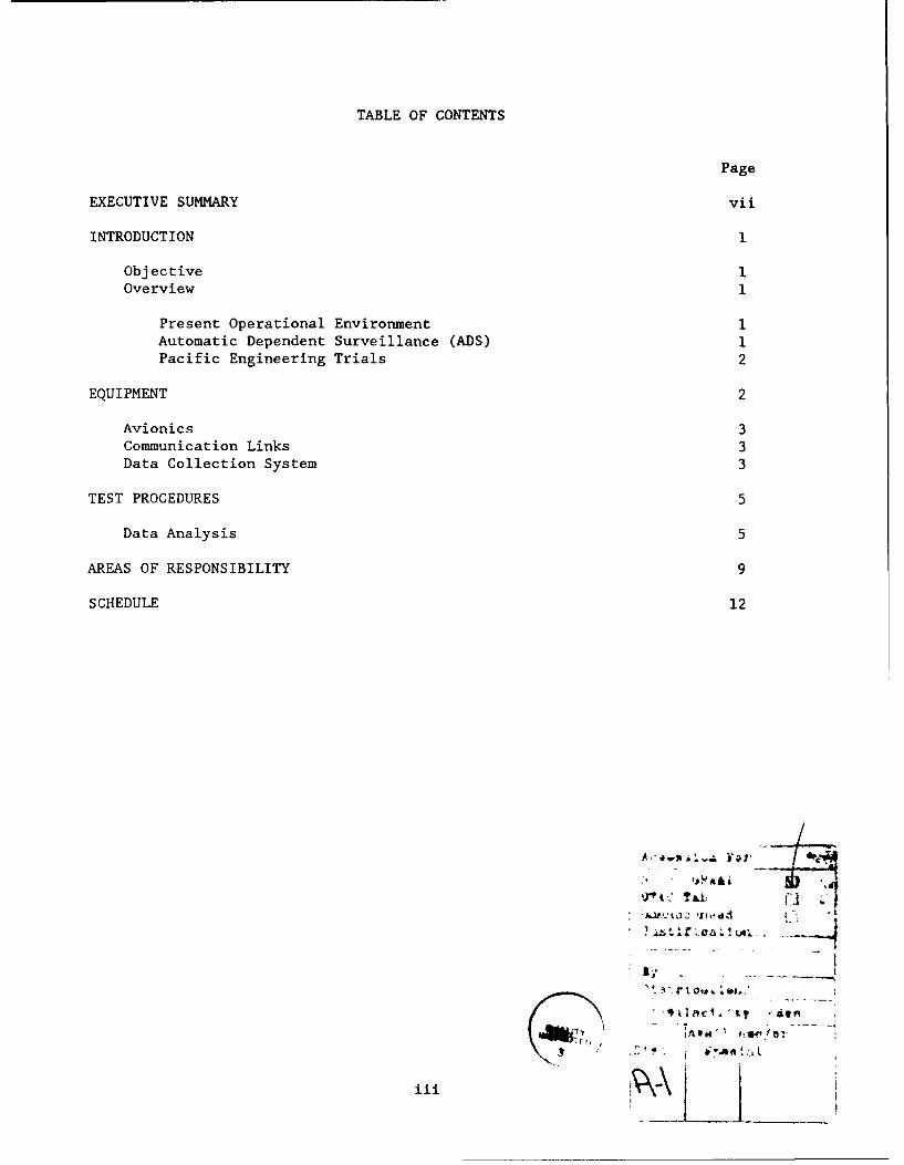
TABLE OF CONTENTS
Page
EXECUTIVE SUMMARY vii
INTRODUCTION I
Objective IOverview I
Present Operational Environment 1
Automatic Dependent Surveillance (ADS) 1Pacific Engineering Trials 2
EQUIPMENT 2
Avionics 3Communication Links 3Data Collection System 3
TEST PROCEDURES 5
Data Analysis 5
AREAS OF RESPONSIBILITY 9
SCHEDULE 12
,r'" t T J&i;
... . f .0 L .. . .(A
-,l
iii

LIST OF ILLUSTRATIONS
Figure Page
1 Test Configuration 4
2 HF Mandatory Position Report Format 6
3 ACARS Satellite Position Report Format 7
4 Converted Satellite Position Report Format 8
5 End-to-End Message Transfer Delay 10
6 Data Link Validation Report 11
7 Satellite Data Link Validation Schedule 13
v

EXECUTIVE SUMMARY
This plan describes the validation process of a satellite data link for use inair traffic control (ATC). Aircraft equipped with satellite communicationavionics will relay position reports through a satellite to a ground earthstation (GES). From the GES, messages will be passed, using the AeronauticalRadio, Inc. (ARING) Data Network Service (ADNS), to the Federal Aviation
Administration (FAA) Technical Center. They will be recorded by acommercially available computer. These messages are position reports which
will be compared to reports using high frequency (HF) radio communicationwhich contain similar information. These reports will be compared to measure
the relative performance of the two communication links. The results of thecomparisons between the different links will be used to determine the
suitability of satellite communication as a replacement for HF for oceanicATC.
vii

INTRODUCTION
OBJECTIVE.
The objective of this test is to determine the suitability of satellite datalink for use in oceanic air traffic control (ATC). This will be done bycomparing the performance of existing high frequency (HF) voice communicationslinks against the satellite data link, by post-flight comparison of HF andsatellite progress reports. The results of the comparisois between thedifferent links will be used to determine the suitability of satellitecommunication as a replacement for HF for oceanic ATC.
OVERVIEW.
PRESENT OPERATIONAL ENVIRONMENT. Presently, in the oceanic airspace pilotsrelay progress reports, at fixed points, to air traffic controllers via HFvoice communication links. The current procedure for relaying messages in thePacific is as follows: the pilot reads position information from the Inertial
Navigation System (INS) at a specified reporting point and transmits it byvoice over HF radio. An operator at the Aeronautical Radio, Inc. (ARINC)facility listens to the message and transcribes it exactly as he hears it.The transcribed report is then transmitted over the data network to the ATCcenter at Oakland or Anchorage. In Oakland, the progress reports are
processed by the Oceanic Display and Planning System (ODAPS), which maintainsflight plans, prints flight strips, and provides a situation display for the
controller.
The environment in which position reports are transmitted is conducive tohuman error. Errors may be made when the pilot reads the information to theARINC operator, and when the operator hears and types the message. Otherproblems include frequency congestion, garbled messages, delays, the expenseof operators and equipment, and the lack of automation due to the use of
manual methods.
AUTOMATIC DEPENDENT SURVEILLANCE (ADS). Due to the inadequacy of the voicecommunications link, the ADS concept was originated to eliminate existingproblems and enhance the present ATC system. The most significant improvementof oceanic ATC is the use of satellite as a data link that provides accurate,
fast, and reliable ATC information.
ADS is a system that uses a data link for relaying automatic, timely, andaccurate position reports to ATC facilities. The information is generated by
the aircraft's on-board avionics and sent over a data link. It is thendisplayed to an air traffic controller for use in planning and separating
aircraft.
The FAA is in the process of implementing ADS. This will permit changes inprocedures which will result in operational benefits to airlines and the FAA.
It is anticipated that ADS will eliminate the need for HF progress reports.

PACIFIC ENGINEERING TRIALS. The FAA is currently operating an ADS PacificEngineering Trials (PET) program designed to evaluate technical andoperational aspects of ADS. As part of PET, an airline-operated aircraftequipped with satellite communication (SATCOM) avionics will send automaticposition reports over satellite as well as voice reports over HF at eachreporting point. HF reports will be sent to the Oakland Air Route TrafficControl Center (ARTCC) as usual. A copy of the HF reports and the satellitereports will be sent to the FAA Technical Center for comparison. In addition,a conversion will be made by ARINC which will create an ODAPS format messagefrom the satellite position report. Both centers will use an Apollo computerfor the purpose of data collection. There will be no changes in proceduresduring the test.
The PET is an internatiunal effort in which commercial aircraft with ADScapability will transmit ADS messages during regularly scheduled flights. TheUnited States has cooperative agreements with Japan, Australia, Canada, andothers to jointly participate in data collection and evaluation during thetrials. The evaluation of the satellite link as a potential replacement forthe HF progress reports will be performed with equipment used in the PET.
Depending upon the equipment installed, the ADS report rate may be changed inthe aircraft either manually by pilot input or automatically in response to anuplink command. ARINC will provide multiple addressing capability so thatidentical messages can be routed to ODAPS, the Apollo workstation in Oakland,FAA Technical Center, and MITRE. During the tests, a two-way data linkbetween pilots and controllers will be tested, automatic position reports willbe sent over satellite, data will be displayed graphically to ATC, and datawill be collected at the FAA Technical Center for analysis. Air trafficcontrollers will not use ADS information for oceanic control, only forevaluation purposes.
The flights are scheduled for the first quarter of this fiscal year.Successful results may permit procedures to be modified to allow replacementof the HF reports with the satellite report. The satellite reports areexpected to be more reliable, quicker, and to reduce human error.
EQUIPMENT
The equipment required for this test includes on board HF communicationequipment, SATCOM avionics, communication links (HF voice link, satellite datalink, ground communications network), and an Apollo workstation with a colordisplay. A description of each major component is provided below.
As the test proceeds, new equipment will become available for the Ground EarthStation (GES) and the aircraft. The FAA will decide if this new equipmentwill require additional certification. If so, this test plan will be expandedto include tests of the new equipment.
2

AVIONICS.
The communications avionics consisL of an Aircraft Communications Addressing
and Reporting System Management Unit (ACARS MU) wit! a control display unit
(CDU), a satellite data unit (SDU), a radio frequency unit (RFU), a high power
amplifier (HPA), and a low gain antenna (LGA).
The CDU enables the pilot to create downlink messages and view uplink messages
through the ACARS system. ACARS provides the crew interface to a VHF datalink. It allows limited control of the data link and has the capability to
send and receive messages. ACARS units have been modified in order to
communicate through the satellite network by providing an interface to the
SDU.
The satellite avionics consist of the SDU, RFU, HPA, and LCA. The SDU
converts messages from ACARS format to a format suitable for transmission over
the satellite link and controls the SATCOM avionics. Signals are presented tothe RFU for frequency conversion, amplified in the HPA, then transmitted
through the LGA.
Some airlines will require additional equipment in order to participate in
this project. Many of these aircraft have an Aircraft Condition Monitoring
System (ACMS), which will be used to interface to various aircraft sensors and
can perform some limiteu message creation functions. The ACMS interfaces with
the ACARS MU to transmit and receive messages.
COMMUNICATION LINKS.
There are threc communications links involved in the HF/SATCOM validation
process, as shown in figure 1. The first is the HF voice link. Pilotscurrently relay all messages from the aircraft via this link. The messages
are transcribed by an HF radio operator and transferred as data to the end
user (e.g., controller or airline).
The second link is the satellite data link. International Maritime Satellite
Organization (INMARSAT) satellites provide coverage of the Pacific Ocean
operating through the GES at Santa Paula, California. The CES provides the
connection and interface between the RF satellite link and the terrestrial
network. initially, the GES will have the capability to handle 15 aircraft.
Communication Satellite Corporation (COMSAT) provides the satellite receiving
station services. The satellite system design conforms to international
standards.
The third link is the terrestrial data network. During this test, the
existing ARINC Data Network Service (ADNS) will be used to send messages from
the GES and the HF operations center. Airlines participating in the PET
subscribe to this network. ARINC records the messages and identifies the link
in use. These are processed through their data link processor (DLP) which
converts the satellite message to ODAPS format, and transfers it to the enduser.
3

w c
E0
0CL
0
ca
C)
00
a:
0G)i
w
wI:
00
0 -0
0.ni 0 .CL 0tia 0
44

DATA COLLECTION SYSTEM.
An Apollo computer workstation will receive, collect, and graphically display
the data. It is based on MITRE's ADS situation display software. Flight
routes, waypoints, sector and control center boundaries, continental land
masses, and aircraft position from HF or ADS reports are displayed on the
workstation's 19-inch color monitor. All data will be recorded and analyzed
at the FAA Technical Center.
TEST PROCEDURES
During these tests, airline-operated aircraft equipped with SATCOM and ACARS
will fly regular routes, making regulir reports over satellite and HF.Position reports will be sent over H. to ATC as usual. The FAA Technical
Center will receive a duplicate of these position reports from th- ADNS.
Pilots will create satellite positon reports using existing ACARS message
types. Note that these are diffei,&nt from the ADS type messages used for the
PET.
Initially, pilots will create free text messages manually. At a later date,menu driven display pages will help pilots create mcssages. Eventually, this
process will be fully automated.
These reports will be sent over satellite at each waypoint and transmitted to
the FAA Technical Center via the ADNS. ARINC wiLl receive and process thesemessages through their DLP to convert them to ODAPS format. At the FAA
Technical Center, HF and satellite reports will be recorded for post-flight
comparison between the different links.
To aid in the comparison, flight strips will be obtained from Oakland Center
and used to determine the cleared flight plan and the actual path flown by the
aircraft. Pilots will be requested to fill out logs for each flight conducted
as part of this test. In addition, transcripts of the communications between
controllers and ARINC operators will be provided for use during this test.
DATA ANALYSIS.
The tests involve comparisons between the different message types and will bechecked against established formats. Figure 2 shows the format of the HF
position report. Figure 3 shows the satellite position report format created
by pilots using ACARS.
Figure 4 shows the satellite position report converted to ODAPS format.
Specifically, for each set of messages at each reporting point, every fieldwill be compared to the corresponding field of the other messages. The fields
should contain the same information. Messages will be matched according to
their time of applicability (i.e., when the waypoint was crossed).
If any discrepancy should occur, pilot flight logs, controller flight strips,and ARINC message transcripts will be used to find the source of the error.
Three comparisons will be performed as described below.

o a LUJ 0
C)) _a) ClC:
00
LUJ
- - L1 U) -a,
< > F C C< 0 L-LU 0 >~~a
CU E .- 'I,~
CC
LIJ0 CL '
c- CU CL(
c) aU Ea
cm LU <-- -
37 -;
-J L H LL)U L LULU-
a) w a <LU >O U o fn 0 o C)r(jL-D U )C 0 )0- w
LJ U) 0 01 U) LU u CC) <-
crj nm < -3
i U U) CF- ZLLLC
<~a <0 ) J(Jo0
LL.
G,-
6j

-)
.00
a)(V
> 1
>j >= U) ,QV oV O
Z. L U) 0
0 0 0
u-J-
z u L ON 0
cu ON X mi~
C? z
0% 0a% X
~x'-(V
xxx X
>~ LI)x L
a, XCLL X V
I-) X
cr<)( 0U) 0 ___
0. ,.<
(I)n
uJu Loo(
7m

E
0'
4) C:- 0U
.0 0 cuW4)- L- cuC
(C C < ~.0) . 4) C= -- z L LO LO
d) >IV 0CC>) - -LU 0 )w ) M
o0 0 >.u ) UC I-LU
0 10 W -:
0.4.~ Er :3 M 0 LL )uz > CUL f 4.- U')D<
0 c C 0 LLUac
o) a) Q~ -0 LU
C u~L W 0IM
or '0 4) u < 0 wL
X C LU _U ID U Ix LU UOJCo w 0 WJ ~ I 0 IX Lf r L L-LJc
z~ <) V) O C4) --(9 C 0Dz ui ID j >D L 00-
0 0) IL IL 0a Hr> <~ Z 0 c
0~ a'J <4 <0)
zz0
ON H
00
0.0
0
E0) L 0 0)H
U-)f ) .I u
C C: XLO (n -U U
00
0%_ ONUL
O, i>
_ __)_ d m 4)a 04)a u a - 0X D) qu V_ LO J0 1
z > 8

The first test is to compare the converted satellite data to the HF report.This will provide a simple end-to-end check on performance of both links, and
is of primary importance. If discrepancies occur, the source of the problem
will be identified by making additional comparisons.
The second test is to compare the satellite position report to the HF report.
This will verify that pilot data inputs conform to the pilot voice reports.
The third test is to compare the satellite position report to the ODAPS
satellite report. The converted satellite report should have the sameinformation as the original message but in a different format. This will be
done to verify that the conversion being done in the DLP is carried outproperly.
Typical errors that are expected to occur are missing reports, format errors,missing fields, errors within the field, duplication of messages, message
mismatches, and messages that are out of sequence. Each will be identified
and tabulated, and presented statistically.
An attempt will be made to determine the time offset between Universal Time
Coordinated (used for control) and ADNS (used for time stamp). This offset
will be used to determine the delays inherent in each link by comparing the
waypoint crossing time to the time the message is entered into the ADNS. An
example of a bar plot representing transfer delays on the satellite link is
shown in figure 5. A similar plot will be made for the HF link.
Statistical plots will be made for all messages received (HF data, satellite
position reports, and converted satellite reports), the errors within the datablocks, the discrepancies between the message comparisons, and time variation.
Results of the analysis will be presented on a bar plot. Figure 6 shows an
example of total messages received from the three different sources and theresults of report comparisons. Monthly cumulative reports will be prepared as
the tests progress. Additional analysis will be performed if the need arises.
AREAS OF RESPONSIBILITY
ACD-330 will be responsible for project management, data collection, analysis,
data reduction, and publication of a report.
MITRE will supply the software for processing and displaying the ADS reportsat the FAA Technical Center and Oakland ARTCC.
United Airlines and Northwest will provide the aircraft.
Collins Air Transport Division will provide the avionics and the ground
station interface, as developed under contract to INMARSAT.
INMARSAT will provide satellite services.
COMSAT will provide the satellite receiving station services.
ARINC will provide the data network services.
9

44 4 4 4 4 ( 4 ( 4
0~~t 4 4 4 4 14444
LUL
LLJ
0Q '
LuLU
m -JLLLU
LU zC) U
LUj00 <
Mil Zi
0c-
LL.U)
LUL
C~)(0
,0
I LIJ
(~L) OWLU U,
Hu
LI-
<0£
< 10

00GN
LLJU
cr U-
U~L < 0L
LUL) HL CC 0
00
LLI 0 0- L2
(Du~ UU crC c0 Lu 0
0 0 -
z
C LUJ 0 0 <crTaC-c HC
LJU LLJcr<
~~OLJH - H ) c c
LLD
LLJ u
C-z ~ 0
C) 0 L icrujr
w 0 0 0 0
0L 0
S9YVSS3WJ O 8L-JflN

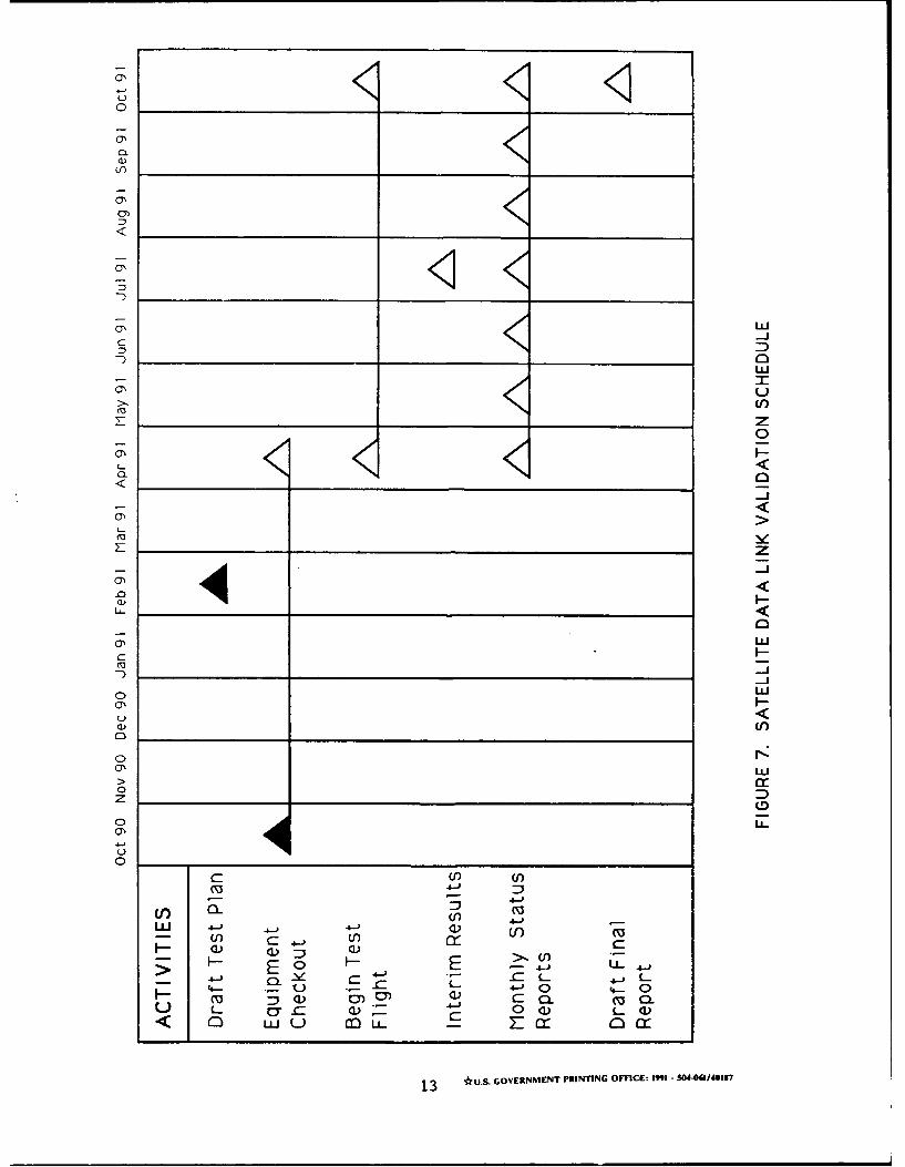
SCHEDULE
Flight tests began in October 1990. Interim results will be presented in
1991. Also, a final technical report describing the test results based upon
the comparison between the voice HF link and the satellite link will be
published in October 1991 (see figure 7).
12
0.
uLI=-J
LLI
___7_ z0
L--<
0'
2- z
U - _ _ _ _ _ _ _ _ _ _ _ ____
-i
0 WL
U<
C)'
0o
o LL.C-,
0c U)
"S 4 -J
J f) 4-0L
> - H E 4) L -
u c a) (
< 0 LLJ u )LL - 0 cr
13 *u.S. GOVERNME~NT PRINTING OFFCE: I"99- 384-061/40137