Satellite Communications IBEX 2011 - National Marine Electronics
77
© KVH Industries, Inc. Satellite Communications IBEX 2011 Installations and New Technologies IBEX ‐ Louisville, KY ‐ October 2011
Transcript of Satellite Communications IBEX 2011 - National Marine Electronics

© KVH Industries, Inc.
Satellite Communications IBEX 2011
Installations and New Technologies
IBEX ‐ Louisville, KY ‐ October 2011

© KVH Industries, Inc.
Agenda
• Trends• Technology
– Properties of satellites and satellite signals– Factors affecting satellite coverage– Satellite TV services
• TV systems– Home vs. marine– DVB technology
• Installation– Common issues to watch out for– Basic VSAT installation

© KVH Industries, Inc.
INDUSTRY TRENDS

© KVH Industries, Inc.
SATCOM for the Marine Market
• Communications at sea changing dramatically– Yachts 32′ and larger need communications systems for work,
and as a means of receiving entertainment and news
• New services offer: – Global coverage – Broadband speeds – need for broadband is growing– Voice over IP (VoIP)– Affordable prices
• Communications requirements– Small– Cheap– Light– Global

© KVH Industries, Inc.
Current Trends
• Bandwidth needs are increasing for yachting lifestyle– Charter vessel needs– Security– Crew morale
• Inmarsat owns a large majority of MSS traffic– Reliability– Proven name– Introduces new technologies
• Iridium – True global coverage– Most known for handheld phones and
2.4 kbps data– Offers faster Internet speeds with
installed multi-antenna solution
• Globalstar– Most known for handheld phones and
9.6 kbps data– Offers faster Internet speeds with
installed multi-antenna solution• SkyMate
– E-mail, weather, voice/fax services for recreational boaters
• VSAT business has seen tremendous growth– Over 100 airtime operators/providers– Various antenna manufacturers
• KVH• Sea Tel, Orbit, KNS, Intellian
– 4 major platforms• ViaSat / KVH (CRMA)• iDirect, Hughes HX, Gilat (TDMA)

© KVH Industries, Inc.
Active VSAT Terminals/Segment
© KVH Industries, Inc.
Satellite TechnologyUnderstanding the Basics

© KVH Industries, Inc.
What Is A Satellite?
• A device in space that orbits (loops around) the earth
• TV, VSAT, and Inmarsat satellites are located over the equator at a set longitude– Geosynchronous orbit
• Earth stations transmit TV signals to satellites– Satellites rebroadcast the signals to fixed “footprints” on Earth
• Satellites broadcast over a certain frequency range

© KVH Industries, Inc.
Satellite TVRO Band Designations
• C-Band at 3.7–4.2 GHz• Ku-Band at 10.9–12.75 GHz• Ka-Band at 18.0–20.0 GHz• Important general information about the different
bands:– The lower the frequency, the larger the antenna– The higher the frequency, the more weather will affect it– It is common practice for the higher frequency antennas to go
larger than normal to compensate for weather losses

© KVH Industries, Inc.
Orbits of No. American Satellites

© KVH Industries, Inc.
It’s Crowded Up There!

© KVH Industries, Inc.
Satellite Footprints
• Coverage area of the beam called a “Footprint”• Each satellite service has its own unique
footprint– Coverage areas subject to change by service provider
• CONUS beam– Covers the continental U.S.
• Spot beam– Covers a small area of the country– Used for local channels

© KVH Industries, Inc.
Effective Isotropic Radiated Power
• “EIRP”• Satellite transmits signals at certain power level to
compensate for losses from atmosphere– Transmitted on channels called “transponders” separated by frequency
• Power-level contours indicate locations of high and low power areas
• Fringe area of the beam = weakest signal• Dish size of antenna determines
minimum EIRP for good reception– The lower an antenna’s minimum EIRP, the
greater its reception range

© KVH Industries, Inc.
Representative CONUS Footprint

© KVH Industries, Inc.
Line of Sight Required
• Antenna must “see” the satellite to receive its signals

© KVH Industries, Inc.
What affects SAT TV reception?
• Blockage!• Antenna must have clear view of TV satellite
– Line-of-sight required
• Common causes of blockage:– Buildings– Masts, rigging– Bridges– Heavy rain, fog, etc.
• Higher satellite elevation = Less blockage and weather affect

© KVH Industries, Inc.
Elevation to DIRECTV 101W

© KVH Industries, Inc.
Satellite Signal Polarization
• What is Polarization?– Orientation of the signal– Allows frequency overlap/reuse, increases capacity
• Circular Polarization– Left Hand Circular Polarization (LHCP)
• LHCP (18V) = even transponders– Right Hand Circular Polarization (RHCP)
• RHCP (13V) = odd transponders
• Linear Polarization– Vertically or horizontally polarized– Signals transmitted offset by 90°– LNB must be adjusted (“skew”) to receive – Sky Mexico (PAS 9) signals are linearly polarized
Left-Hand Circular
Right-HandCircular
HorizontalLinear
VerticalLinear

© KVH Industries, Inc.
Linear Signals (e.g. Sky Mexico)
• To receive linearly polarized signals, antenna must be equipped with a linear LNB (low noise block)
• LNB must be oriented in the same way as the satellite signal– This is called the LNB’s “skew”
Bad Skew Good Skew Ideal Skew

© KVH Industries, Inc.
PAS 9 Skew Map
Note: Map shows approximate values only

© KVH Industries, Inc.
Service Providers in No. America
• DIRECTV®
– Continental U.S. coverage– Standard-definition programming from Ku-band satellites at
101° W and 119° W– High-definition (HD) programming from Ka-band satellites at
99° W and 103° W (requires TracVision HD7 antenna)• DISH® Network
– Continental U.S. coverage– EchoStar Ku-band satellites– DISH 500 programming from 119° W and 110° W– TurboHD (DISH 1000) adds HD and local programming from
either 129° W or 61° W• Bell® TV
– Formerly ExpressVu– Canadian coverage– Nimiq Ku-band satellites– HD and standard programming from 91° W and 82° W

© KVH Industries, Inc.
Satellite Info Web Sites
• www.lyngsat.com• www.satbeams.com• www.satlex.de• science.nasa.gov• www.kvh.com/footprint
NOTE: KVH does not validate the information contained on third-party web sites, and their content is subject to change without notice.

© KVH Industries, Inc.
Home Satellite TV System

© KVH Industries, Inc.
Home System
• Reflector – Reflects satellite signal to Low Noise Block (LNB)
• LNB– Collects the satellite signal– Converts signal from Ku/Ka to L-Band– Amplifies the signal– Sends signal down RF coax cable to receiver
• Receiver– Decodes the satellite signal– Sends audio/video to the TV– Supplies power to the LNB– 2nd receiver needed to watch different
channels on a 2nd TV

© KVH Industries, Inc.
TracVision® Satellite TV System

© KVH Industries, Inc.
TracVision Antennas
• Automatically searches the sky and finds the satellite– Using DVB technology
• Tracks the satellite while vessel is in motion– Tracks by RF signal strength
• Antenna housed in a protective dome• LNB collects signals that bounce off
reflector and splash plate, converts and amplifies the signals, and sends signals to the belowdecks receiver(s)
Splash PlateReflector Feed
Tube
LNB

© KVH Industries, Inc.
DVB® Technology
• DVB = Digital Video Broadcasting– Allows the antenna to automatically find the correct satellite
• Antenna identifies a satellite by its unique characteristics:
• Frequency– Number of signal peaks that pass a fixed point in one second (MHz)
• Symbol rate – Number of symbols (group of data bits) transmitted per second
(Mbit/second)
• FEC code = Forward Error Correction– Percentage of bits used for data and for correction of transmission
errors (e.g. 5/6 = 5 data bits transmitted for each error correcting bit)
• Network ID– Identification code unique to each satellite (hexadecimal)

© KVH Industries, Inc.
VSAT TECHNOLOGY

© KVH Industries, Inc.
TDMA vs CRMA
• TDMA = Time Division Multiple Access– Protocol used by traditional VSAT systems– Time slots assigned to each vessel on the network, separated
by timing gaps– Imposes transmission delays and reduces the data rate
experienced onboard– Antenna must be large enough to focus its transmitted energy in
a narrow beam that will not interfere with adjacent satellites• CRMA = Code Reuse Multiple Access, spread-
spectrum technology – Protocol used in new mini-VSAT BroadbandSM
– Vessels transmit data immediately in bursts – Reduces contention issues, transmission delays, and network
slowdowns– Return link transmissions are spread across a much wider
frequency spectrum– Low power transmissions don’t interfere with neighboring
satellites, allows wider beam and makes small dish size possible

© KVH Industries, Inc.
How TDMA Works

© KVH Industries, Inc.
How TDMA Works (cont’d)

© KVH Industries, Inc.
How CRMA Works

© KVH Industries, Inc.
How CRMA Works (cont’d)

© KVH Industries, Inc.
TV Installation
© KVH Industries, Inc.
Common Installation Issues
• Incorrect wiring• Substandard RF connectors
– Always use Snap-N-Seal® F-connectors– Use proper tools to terminate
• Insufficient or unstable power– Install an AC/DC power supply
• Poor grounding• Antenna mounted near an obstruction or radar• Shipping restraints not removed• Poor external sensor location

© KVH Industries, Inc.
Choosing the Antenna Location
• Clear of any obstructions – Pay attention to the look angle
• At intersection of vessel’s fore-and-aft centerline and midships
• Mounting surface must be: – Flat– Level (within 2)– Sturdy enough to carry the antenna without
vibration
• Keep out of line from nearby radars!– Ka-band signals are particularly vulnerable
to radar interference
• Follow manufacturer cable guidelines and do not exceed their recommended lengths

© KVH Industries, Inc.
Mounting the Antenna
• Find a good, sturdy mount location for optimal antenna performance– Clear of other antennas already on boat
• Types of mounts– Bracket-mounted - need a drill and the appropriate bolts to
install the bracket– Flush-mounted - requires making an accurate cut-out– Tuna-tower, pole/pedestal mounting, clamp, ratchet– Custom
• Use proper hardware, insert bolts from above, and seal
• Follow manufacturer’s instructions• Dual dome installations for aesthetics
– Matching domes add balance and symmetry – Domes can be colored to match the boat

© KVH Industries, Inc.
Mounting Below Decks Equipment
• Identify a cool, dry, well-ventilated area • Allow plenty of room for the connecting
cables• Ensure front panel is accessible to
the user• Rack or surface mounting• Case or bracket options

© KVH Industries, Inc.
Cabling
• Double check vessel power– Stable power source– Proper grounding
• Use the appropriate RF cables • Know the minimum bend radius
– Belden RG11/u is a 4" minimum bend radius– Belden RG6/U has a 2.75" minimum bend radius
• Cables must be terminated properly with the right connectors
• Use proper stripping, crimping or compression tools
• Sealing cable access – Prevents water from seeping into the boat
• Verify all wiring conforms to the manufacturer’s wiring diagram

© KVH Industries, Inc.
Example: Wiring a TV System
© KVH Industries, Inc.
Important Points to Remember
• Most satellite TV signals are broadcast on Ku-band (10.7-12.7 GHz)– DIRECTV HD is broadcast on Ka band (18.3-18.8 GHz)
• Signals in U.S. are circularly polarized (LHCP = 18V; RCHP = 13V)
• To receive linearly polarized signals (such as PAS 9), antenna’s LNB must be set to the correct skew– KVH’s TracVision M7 and M9 can adjust skew automatically
• Heavy rain and other weather disturbances can disrupt reception
• Line of sight required– Antenna must point at the satellite

© KVH Industries, Inc.
Important Points to Remember (cont’d)
• Antenna must be located within a satellite’s footprint and be rated for its EIRP to receive the signal – Larger dish size = lower minimum EIRP = greater range
• The further south you go, the higher the satellite elevation
• DVB technology allows antenna to positively identify a satellite by its unique characteristics, such as its network ID

© KVH Industries, Inc.
Common VSAT Installation

© KVH Industries, Inc.
Tools You Will Need
• Before you begin, gather these tools:– Flat-head and Phillips-head screwdrivers– Electric drill and 5/16" (8 mm) bit– 3.5" (89 mm) hole saw– 1/2" socket and 7/16" socket– 7/16" open-end wrench and 7/16" torque wrench
set to 15 inch-pounds– Light hammer and center punch– Adhesive tape – Scriber or pencil– Silicone sealant or self-vulcanizing tape– Wire strippers and terminal lug crimper– Two RF coax cables of appropriate type– Proper connectors and termination tools for RF cables– Windows 7, Vista, or XP laptop with the latest version of the
TracPhone V-series Flash Wizard– Isolation transformer, if required

© KVH Industries, Inc.
Mounting Location for Antenna
• Minimize blockage– Antenna requires a clear view of the sky
• Mounting surface must be:– Strong enough to support the antenna’s
weight – Rigid enough to withstand heavy vibration– Flat– Level
• Mount above crew and passenger areas to reduce the risk of RF radiation exposure
• Avoid placing the antenna near magnetic compasses or other onboard antennas to prevent interference
• Do not place the antenna at the same level as the radar– Mount the antenna outside its beam path

© KVH Industries, Inc.
Mounting Location Example
• Which mounting location is best?
• Answer: Location B– Locations A and D have blockage issues and are in areas
frequented by the crew, risking RF radiation exposure– Location C is directly in line with the radar

© KVH Industries, Inc.
Mounting at the Centerline
• The antenna should be as close as possible to the intersection of the vessel’s centerline and midships– Particularly important on leisure
vessels– Helps minimize the effects of pitch and
roll on the antenna
• On larger commercial ships, where a central location is impractical, this guideline is less critical

© KVH Industries, Inc.
Antenna Dimensions
Side View Bottom View

© KVH Industries, Inc.
Lay Out Antenna Mounting Holes
• Use the supplied template• Ensure “FWD” arrow points
toward the bow and is parallel with the vessel’s centerline
• Drill the four 5/16" (8 mm) mounting holes
• Cut out the 3.5" (89 mm) cable access hole– Smooth the edges of the hole to
protect the cables from abrasion– Apply anti-chafe material around
cables, if necessary• Apply the foam seal
– Center around the access hole– Attach to the mounting surface, not to
the antenna’s baseplate

© KVH Industries, Inc.
Remove the Shipping Restraints
• Remove the radome– Remove and save the #10-32 screws– Set the radome aside in a safe place
• Remove the two shipping restraint screws– Save these restraints for future use

© KVH Industries, Inc.
Wiring the Antenna
• Connect three cables to the baseplate– One power/data cable, 100 ft (30 m) supplied– Two RF cables for transmit and receive, not supplied– Note: A 150 ft power/data cable is available
• Use the proper 75Ω RF cables– 15-50 ft (5-15 m): RG-11– 50-100 ft (15-30 m): LMR-400-75– 100-150 ft (30-45 m): LMR-600-75– Label both ends of the cables (“TX” and “RX”)– Tighten to 20 inch-pounds of torque
• Route all cables belowdecks– Power/data to the control unit, RF to the modem– Ensure adequate service loops, strain-relieve cables at both
ends, and maintain the minimum bend radius• Seal the antenna’s RF cable connections with silicone
sealant or equivalent• Attach the connector cover and seal the cable access
hole

© KVH Industries, Inc.
Wiring the Antenna (cont’d)
• If using LMR-400-75 or LMR-600-75– Connect the LMR cables to the supplied 3 ft
(0.9 m) RG-11 pigtail cables with feed thru adapters– Connect the RG-11 pigtail cables to the antenna
• Three options for using RG-11– Terminate your RG-11 cables with right-angle
“F” connectors to connect to the antenna– Use the supplied RG-11 pigtail cables to connect
your RG-11 cables to the antenna– Use the optional 50 ft (15 m) pre-terminated RG-11
cables from KVH • Each RF cable run must not exceed
6.5 dB of insertion loss– RG-11 loss: 0.084 dB/ft (0.276 dB/m)– LMR-400-75 loss: 0.06 dB/ft (0.195 dB/m)– LMR-600-75 loss: 0.04 dB/ft (0.13 dB/m)– An in-line connector adds at least 0.2 dB of loss
© KVH Industries, Inc.
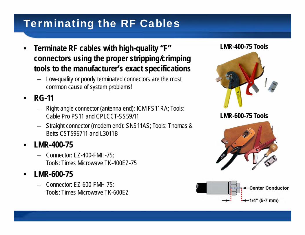
Terminating the RF Cables
• Terminate RF cables with high-quality “F” connectors using the proper stripping/crimping tools to the manufacturer’s exact specifications– Low-quality or poorly terminated connectors are the most
common cause of system problems!
• RG-11– Right-angle connector (antenna end): ICM FS11RA; Tools:
Cable Pro PS11 and CPLCCT-SS59/11 – Straight connector (modem end): SNS11AS; Tools: Thomas &
Betts CST596711 and L3011B
• LMR-400-75– Connector: EZ-400-FMH-75;
Tools: Times Microwave TK-400EZ-75
• LMR-600-75– Connector: EZ-600-FMH-75;
Tools: Times Microwave TK-600EZ
LMR-400-75 Tools
LMR-600-75 Tools

© KVH Industries, Inc.
Terminating LMR-400-75
• Cut the cable evenly• Gently round the end of the cable
– Cutting the cable deforms the end – Make sure the center conductor is centered within the cable
• Place the heat shrink sleeve and metal ferrule onto the cable
• Strip the end of the cable to expose the center conductor– Insert the cable into the #1 end of the stripping tool– Rotate the tool clockwise around the cable until the tool turns
easily

© KVH Industries, Inc.
Terminating LMR-400-75
• Remove residual plastic from the center conductor, if necessary
• Strip the cable jacket– Insert the cable into the #2 end of the stripping tool– Rotate the tool clockwise around the cable until the tool turns
easily

© KVH Industries, Inc.
Terminating LMR-400-75
• Deburr the center conductor– Use the DBT-02 tool– Do not nick the aluminum tape
• Flare the braid• Insert the cable into the connector body until the
dielectric is seated– Make sure all braid wires are on the outside of the connector
body – Make sure the aluminum tape is inside the connector body
• Trim any excess braid– Braid should assemble flush to within 1/16“ (1.6 mm) of the
connector shoulder

© KVH Industries, Inc.
Terminating LMR-400-75
• Slide the ferrule over the braid• Crimp the ferrule in place
– Crimp close to the connector body, then again further back from the connector
– Avoid crimping the cable jacket
• Slide the heat shrink sleeve onto the connector body and heat it to compress in place– Heat shrink should extend from the rear of the connector to the
cable jacket– This forms a weather seal
• Check cable continuity and ensure the center conductor pin measures between 0.20"-0.28" (5-7 mm) in length from inside the nut to the tip

© KVH Industries, Inc.
Position the Antenna
• Centered over foam seal• “Forward” arrow pointing toward the
bow of the vessel and parallel to the vessel’s centerline

© KVH Industries, Inc.
Mount the Antenna
• Use the supplied 1/4" hardware– Apply the supplied anti-seize lubricant to the threads
• Insert bolts from above• Tighten the bolts until the foam seal is
compressed and the rubber feet are bottomed against the mounting surface– Use caution if using power tools because high installation
speeds can damage the threads

© KVH Industries, Inc.
Reinstall the Radome
• Use the supplied #10-32 screws• Install supplied plastic caps over
the screws

© KVH Industries, Inc.
Wiring Transmit/Receive RF Cables
• Connect the two RF cables to the modem– MRX cable to “J3 Rx RF”– MTX cable to “J2 Tx RF”
• Do not reverse the connections!

© KVH Industries, Inc.
Wiring the Power/Data Cable
• Connect the power/data cable wires to the terminal strip connector– Diagram refers to wires by body
color/stripe color– Terminals #3 and #8 not used
• Plug the terminal strip connector into the back of the control unit

© KVH Industries, Inc.
Wiring Control Unit to the Modem
• Connect serial data cable– From “Modem” on Control Unit– To “J4 ACU” on Modem
• Connect BUC power cable– From “BUC Power” on Control Unit– To “J5 BUC Pwr” on Modem

© KVH Industries, Inc.
Wiring the Switch
• Connect the switch to the modem– Use the modem’s “User ENet” jack
(not the “ACU Enet” jack!)– Use a straight-through Ethernet cable
(not a crossover cable)– 25 ft (7.5 m) supplied; max length
200 ft (60 m)
• Connect the customer’s computer(s) to the switch– Use straight-through cables
• CAT5 or better, terminated with RJ45 connectors
• Do not use a crossover cable

© KVH Industries, Inc.
Wiring the MTA
• Connect the MTA to the switch– From “WAN” on MTA– To any port on the switch
• Connect the customer’s analog phone or PABX analog output to the MTA– Use the MTA’s “PHONE 1” jack– The “PHONE 2” jack is not enabled for
use– Use RJ-11 telephone cable– Do not connect a digital phone directly
to the MTA

© KVH Industries, Inc.
Power Requirements
• The TracPhone system requires 3-wire, single-phase AC power– Hot, Neutral, and Ground
• Running the system on two-phase, split-phase, or delta power will cause an unsafe floating ground condition– Risks damage to the antenna and
electric shock, potentially resulting in DEATH!
– In a floating ground condition, the chassis ground will differ greatly from ship’s ground
• Use a suitable isolation transformer if necessary– Install a ground fault monitor behind
the transformer, when required
OR

© KVH Industries, Inc.
Connecting Power
• Use the supplied AC power strip to power the control unit and modem
• Use the supplied AC/DC adapters to power the MTA and switch
• Be sure the vessel is grounded properly in accordance with marine standards

© KVH Industries, Inc.
Belowdecks Mounting Options

© KVH Industries, Inc.
Belowdecks Mounting Options (cont’d)
• Option 1: Case mount– Control unit and modem fit into a standard 6U,
19" case, bolted to a deck– Case kit purchased as an accessory– Control unit + modem = 3U height– Bottom 3U space for expandability
• Option 2: Rack mount– Control unit and modem can be installed in an
existing 19" rack on the vessel
• Option 3: Bracket mount– Control unit and modem can be mounted either
together or separately to a horizontal surface– Brackets supplied in the kitpack
• Be sure to provide adequate ventilation to both units

© KVH Industries, Inc.
Without a Case or Rack Mount
• Attach brackets to the sides of the control unit or modem– Can mount from either the top or
bottom of the unit– Brackets supplied in kitpack– Brackets are identical for control unit
and modem; both units have the same dimensions
• Use appropriate fasteners for the mounting site
• Make sure the mounting site allows plenty of ventilation!– Especially front & back panels

© KVH Industries, Inc.
Mounting Equipment Separately
• You can mount the control unit and modem together or separately
• To mount separately, first detach the control unit from the modem– Four straps– Two brackets
• Save all hardware– In case the user decides to install them
as an assembly in the future
© KVH Industries, Inc.
Strain Relief Brackets
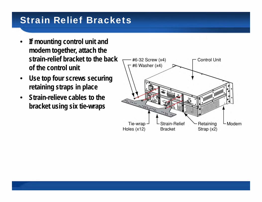
• If mounting control unit and modem together, attach the strain-relief bracket to the back of the control unit
• Use top four screws securing retaining straps in place
• Strain-relieve cables to the bracket using six tie-wraps

© KVH Industries, Inc.
Strain Relief Brackets
• If mounting control unit and modem separately, attach a bracket to each
• Strain-relieve cables to the bracket using six tie-wraps

© KVH Industries, Inc.
Testing the System
• Turn on the system• If the customer has activated
the system, test all applicable web applications– Web browsing, e-mail, voice service
• Access the test web page– Verifies connection to land-based hub– http://208.83.165.11/mbbtest– System doesn’t need to be activated

© KVH Industries, Inc.
Testing the System (cont’d)
• MTA might take 15 minutes to initialize upon startup– Downloads configuration files– Wait until “VOIP” light is lit green
• Place a call to someone on a terrestrial or cellular network– Dial as you would from the U.S., regardless of your location– Ask them to call you back on the customer’s phone number

© KVH Industries, Inc.
Obtain Customer Acceptance
• Give the Welcome Kit to the customer and explain how to use the system– Make sure customer understands the RF radiation hazard– Make sure customer knows how to activate the system for
mini-VSAT Broadband service
• The Welcome Kit includes:– Installation Guide– User’s Guide– Quick Start Guide– Antenna Mounting Template– Warranty Statement– Activation Packet
• Fill out the Installation Checklist– Included in the Welcome Kit– Return it via fax or e-mail– Required to validate your installation

© KVH Industries, Inc.
Questions?