
SAS - MindShare
31
49 3 SAS Overview The Previous Chapter The previous chapter discussed the bus technology developments that motivated and led up to the development of SAS, noting that SAS borrowed ideas from serial transports like Fibre Channel and SATA to develop a next-generation enterprise storage architec- ture. This Chapter This chapter introduces the basic functions of SAS, explaining its method of operation from a very high level view. Terms are defined and examples presented to lay a founda- tion for understanding the basic operation of a SAS link. The layers of the SAS standard are introduced and their responsibilities and interaction are discussed. The Next Chapter The next chapter provides more definitions to facilitate a more detailed understanding of SAS link operation. The different types of devices and expanders are explored, leading to a discussion of topologies and domains, as well as a review of connections. Comparison of SCSI and SAS Operation SAS borrows from many I/O technologies, and those familiar with other serial protocols will find much that is similar in SAS. To understand SAS these people simply need to know which parts of a SAS system correspond to the parts of the transports they already know. Those familiar with SCSI will also find recognize many parts because SAS builds directly on the foundation of SCSI. Let’s begin by looking at a parallel SCSI bus and describing the basics of its operation. www.mindshare.com
Transcript of SAS - MindShare

49
3 SAS Overview
The Previous Chapter
The previous chapter discussed the bus technology developments that motivated and ledup to the development of SAS, noting that SAS borrowed ideas from serial transportslike Fibre Channel and SATA to develop a next-generation enterprise storage architec-ture.
This Chapter
This chapter introduces the basic functions of SAS, explaining its method of operationfrom a very high level view. Terms are defined and examples presented to lay a founda-tion for understanding the basic operation of a SAS link. The layers of the SAS standardare introduced and their responsibilities and interaction are discussed.
The Next Chapter
The next chapter provides more definitions to facilitate a more detailed understanding ofSAS link operation. The different types of devices and expanders are explored, leadingto a discussion of topologies and domains, as well as a review of connections.
Comparison of SCSI and SAS OperationSAS borrows from many I/O technologies, and those familiar with other serial protocolswill find much that is similar in SAS. To understand SAS these people simply need toknow which parts of a SAS system correspond to the parts of the transports they alreadyknow. Those familiar with SCSI will also find recognize many parts because SAS buildsdirectly on the foundation of SCSI. Let’s begin by looking at a parallel SCSI bus anddescribing the basics of its operation.
www.mindshare.com

SAS Storage Architecture
50
SCSI Example
Software Request
In Figure 3-1, a simple SCSI bus is illustrated with one initiator and several targetdevices. The host or client device runs an application program that requests service froma target (which acts as the server for those requests). To make the request, the client callsthe SCSI device driver and the driver sends a command over the system I/O bus to theHBA, which is really just a bridge between the SCSI bus and the host system’s bus.
Arbitration and Selection
The HBA, acting as the initiator, must use the shared SCSI bus to send the command.Since the bus is shared, arbitration is required to prevent more than one device fromdriving the bus at the same time. The initiator first needs to win the arbitration to be ableto use the bus and may then select the target device. The SCSI protocol includes an arbi-tration phase and a selection phase for this purpose and the initiator drives its own ID forarbitration. If the initiator wins the arbitration, it next drives the target’s ID to select thattarget for communication. As an example, the ID for each SCSI device is typically justone out of 16 possibilities and is set in hardware with jumpers. SCSI ID values might be
Figure 3-1: Basic SCSI Bus Operation
SCSI HBAInitiator
System IO Bus(eg: PCI-X or PCIe)
Target/ServerDevices
SCSI Bus
Host/ClientSystem
www.mindshare.com

Chapter 3: SAS Overview
51
7 for the initiator and 4 for the target.
Connection in Progress
Once a target is selected, it and the initiator both actively participate in the transactionand are said to be connected. When devices connect, they each store the ID of the otherdevice for future reference (this is called establishing a nexus, which is the relationshipbetween the initiator and target device). The nexus is useful to the target because it maychoose to disconnect while servicing the request and then reconnect to the initiator later.To do that, it must know the initiator’s device ID. The initiator needs the nexus becausemultiple targets might issue disconnects, causing it to have commands outstanding toseveral targets at the same time. When the responses are subsequently returned, it usesthe nexus information to keep track of which target is responding.
Once a connection is established, the target takes control and decides when to transferdata for commands received from the initiator. Since SCSI is a half-duplex bus thismeans some handshaking is necessary for the initiator and target to take turns on thebus. The bus remains dedicated for the use of the two devices until the target releases it.Since the bus is shared, that means all other devices will have to wait until the currentconnection is shut down before the bus is again available. Several transfers might takeplace during the connection between the two devices but eventually the target will dis-connect and the bus will then be free for other devices to use.
Wrapping Up
When the HBA has received the requested response from the target (such as read data) itinforms the client that the command is completed. This would likely be done with aninterrupt, that would invoke the device driver, which would report to the application cli-ent that the data is available in the appropriate buffer. The application would then fetchthe data, completing that command sequence.
Corresponding SAS Structure: Simple Example
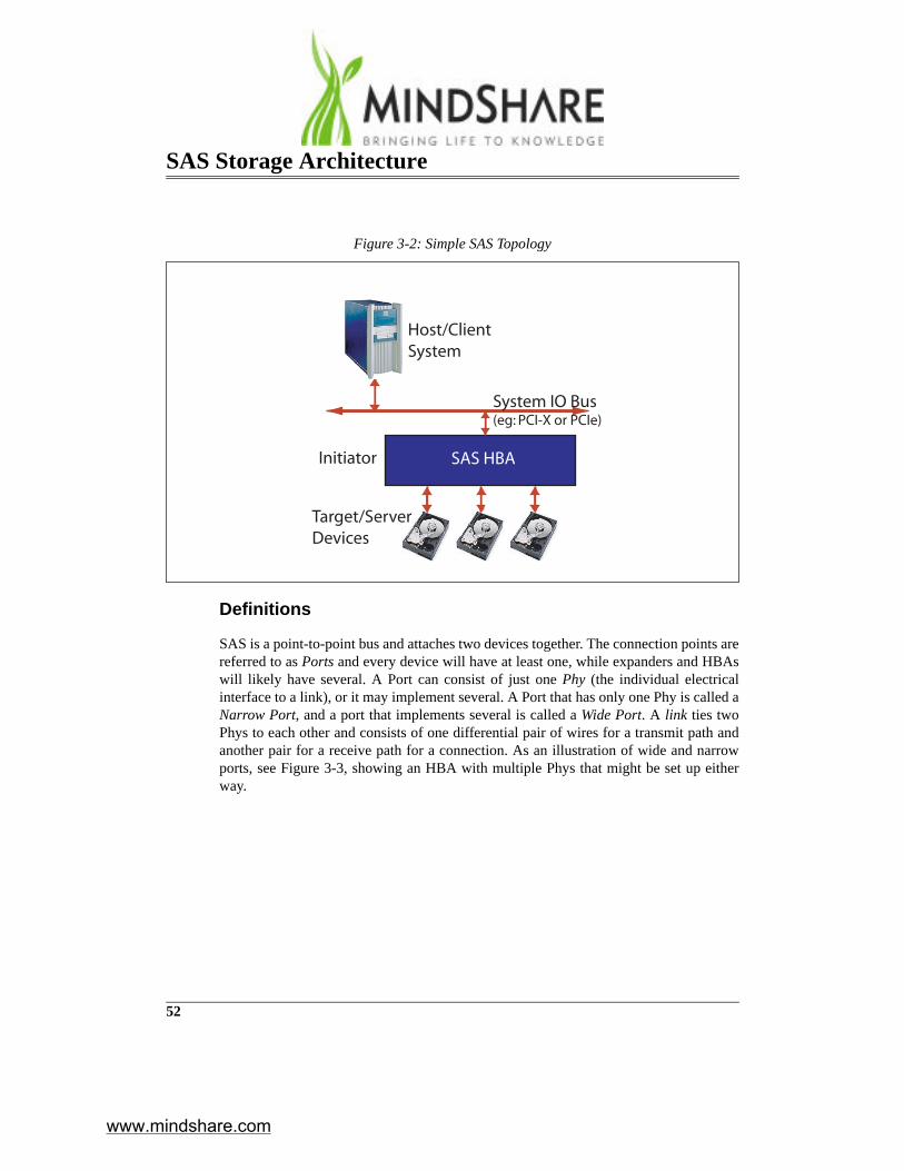
Now consider the simple SAS topology illustrated in Figure 3-2. SAS sets up and com-municates in much the same way as SCSI, but with some differences.
www.mindshare.com
SAS Storage Architecture
52
Definitions
SAS is a point-to-point bus and attaches two devices together. The connection points arereferred to as Ports and every device will have at least one, while expanders and HBAswill likely have several. A Port can consist of just one Phy (the individual electricalinterface to a link), or it may implement several. A Port that has only one Phy is called aNarrow Port, and a port that implements several is called a Wide Port. A link ties twoPhys to each other and consists of one differential pair of wires for a transmit path andanother pair for a receive path for a connection. As an illustration of wide and narrowports, see Figure 3-3, showing an HBA with multiple Phys that might be set up eitherway.
Figure 3-2: Simple SAS Topology
SAS HBAInitiator
System IO Bus(eg: PCI-X or PCIe)
Target/ServerDevices
Host/ClientSystem
www.mindshare.com

Chapter 3: SAS Overview
53
Arbitration and Selection
As before, the client sends a request to the driver which, in turn, forwards it to the HBA.The HBA in Figure 3-2 does not need to arbitrate for access to a shared bus because allthe buses (links) are now point to point. However, to get service the HBA must still con-nect with the target. To do so it sends a connection request that includes the destinationaddress, which is examined to determine to which Port the communication should berouted.
Each SAS device port is assigned a 64-bit SAS address, and requests are directed to adevice based on its address. This address is assigned by the device manufacturer at thefactory and is stored in hardware or firmware on the device. As part of the resetsequence, devices report this unique address to their link neighbor. Later, initiators exe-cute a sequence of steps called the discovery process to read information from expand-ers and make a list of all the addresses accessible to them in the system (see Chapter 7,entitled "Discovery Process," on page 159). It is those addresses that are used to select atarget device. To know which bus should be accessed for this request means the HBAalso needs a mapping scheme to determine which addresses correspond to which bus.How this logic is implemented is vendor specific.
Figure 3-3: Narrow and Wide Ports on an HBA
SAS HBA - 4 Phy
4x
Expander
4x
SAS HBA - 4 Phy
4x
Four Narrow Ports One Wide Port
Several Narrow Ports
www.mindshare.com

SAS Storage Architecture
54
Establishing a Connection
Once the bus topology is known, a connection must be opened over it between the HBAand the destination device before communication can take place. To do that, the HBAport sends a connection request in the form of a special frame called an OPEN Addressframe. The OPEN address frame is routed based on the address and arrives at the desti-nation device. When the target receives this request, it responds by returning a primitiveindicating that it either accepts or rejects the request. This response primitive has noaddress information and is not routed; it simply travels back along the connection thathas been tentatively established by devices in the path between the initiator and target. Ifthe target accepts the OPEN request, every device in the path recognizes that the con-nection has been fully established and the link then acts as a dedicated circuit for com-municating between the two devices until it is closed.
Connection in Progress
Once the connection has been established, the nexus information is stored just as it wasin SCSI. As with SCSI, the target takes control of the bus and decides when to pull writedata or to send read data for the commands it receives from the initiator. Several framesmay be sent in both directions, even at the same time (full-duplex operation is a bigadvantage for SAS), until one or both devices decide it’s time to close the connection.Closing the connection when using SSP (Serial SCSI Protocol) involves having eachdevice first indicate that it’s done with the connection and then send a CLOSE primitive.
Wrapping Up
Just as with SCSI, when the HBA has received the requested response from the target(such as read data) it informs the client that the command is completed. This wouldlikely be done with an interrupt that would invoke the device driver to report to theapplication client that the read data is available in the appropriate buffer. The applicationwould then fetch the data, thereby completing the command sequence.
Concepts for a More Complex Structure
Consider the example of Figure 3-4, in which several HBAs and target devices are con-nected together with expanders (which are functionally similar to switches) to form amore complex network. The selection process becomes more interesting now becauseestablishing a connection request between two devices may involve several intermediatedevices as well. Before we can discuss the features that correspond to the SCSI model in
www.mindshare.com

Chapter 3: SAS Overview
55
this example, we’ll need to cover a few more concepts.
Routing the Requests
Most serial transports use point-to-point buses linked together through some form ofrouting device. The routing device in SAS is called an Expander which forwards servicerequests between the source and destination devices. Generally, there are two basicways of accomplishing that:
• Connection-based routing. Devices establish a temporary dedicated path betweenthe source and destination of the request. This yields the best latency for thosedevices but means others might have to wait for the connection to complete beforethey can get access.
• Frame-based routing. This method routes each individual packet one at a time.This avoids the problem of tying up the resources for a long time, but adds latencybecause the address of every packet must be evaluated for routing.
The first method was chosen for SAS, most likely to help it adhere to its SCSI heritage
Figure 3-4: Complex SAS Topology
Fanout Expander
Edge Expander
Edge Expander SAS HBA 1
SAS HBA 2
www.mindshare.com

SAS Storage Architecture
56
as much as possible. Using this method, the devices route the request based on the SASaddress, and at each step along the way they create a dedicated circuit connection untilfinally the two devices are connected from end to end with a dedicated circuit. This cor-responds to the SCSI concept of connections very well, since the two devices are able tocommunicate as much as they like within a timeout period.
Wide Ports
During the link reset sequence at startup time, each Phy sends its SAS port address to itsneighbor, allowing expanders to observe that several of their Phys all have the sameattached address. For example, consider the four connections between the SAS HBA atthe top of Figure 3-4 and the Fanout Expander. The HBA is designed as a wide port andtherefore must send its unique port address from each Phy during link reset. The FanoutExpander, also designed as a wide port, also sends its unique port address from it's Physto the HBA. Each device upon detecting that the same address has been received at allfour ports, recognizes that a wide port connection exists. When making connectionsbetween the HBA and other devices in this example, the wide ports permit simultaneousconnections to as many as four different devices.
Wide ports allow each Phy to be used for a separate, independent connection. Thoseconnections may be to the same destination address, but it is not possible for one con-nection to use multiple Phys at the same time. This arrangement works well for theHBAs in Figure 3-4 on page 55 because they’re able to simultaneously have several dif-ferent connections in progress with the targets in the network.
Because of the potential for confusion on this point, let’s reiterate a point made earlier:SAS does not allow multiple links to be used for one connection. Other architectureslike PCI Express do allow this, and people familiar with those technologies may natu-rally suppose that SAS works the same way, but it doesn’t. All communication in SAShappens across a connection, which is established as a dedicated circuit, or virtual wire,between one Phy in the requesting device and one Phy in the responding device.
Expanders
SAS expanders act like simple network switches that route connection request framesand then use connections to pass communication frames between devices. As illustratedin Figure 3-4 on page 55, there are two categories of expanders: Fanout expanders andEdge expanders.
• A SAS domain can only contain one Fanout Expander. By definition, a SASdomain is a tree structure and the Fanout Expander is the root of the tree. There areno devices that are hierarchically at a higher level. This type has to be able to keeptrack of all the possible addresses in the domain and consequently needs more
www.mindshare.com

Chapter 3: SAS Overview
57
memory for that purpose.• Edge Expanders are simpler devices that can be cascaded to create more addressing
possibilities. This expander type possesses a subtractive port, which is used as thedefault destination for any connection requests for which it cannot resolve theaddress. That means it doesn’t need to track all the addresses in the network and cantherefore be cheaper than a Fanout Expander.
Expanders receive connection requests on one Phy and attempt to establish an internalconnection between that Phy and the destination Phy determined by examining the des-tination address of the request.
Corresponding SAS Structure: Complex Example
Arbitration and Selection
As before, the client sends a request to the driver which, in turn, forwards it to the HBA.HBA 1 in Figure 3-5 on page 58 sends a connection request onto the Port that it deter-mines has a path to the destination address. In this case, because all of its Phys areattached to the same expander, any of them will be able to connect to any of the devicesthat are accessible to that expander.
Establishing a Connection
Consider the connection example in Figure 3-5. In this case, the connection requestfrom HBA 1 arrives at the Fanout Expander, which informs the HBA that it has success-fully received the request and is arbitrating the request by returning AIP (Arbitration InProgress). Next, it determines to which Port the request should be routed, and then for-wards it onto that link. The next device in the path is an Edge Expander, and it behavesin much the same way. The edge expander next sends a confirmation that it is workingon the request, which the Fanout Expander simply passes through to the originatingdevice. Next, the Edge Expander determines the destination Port and forwards therequest onto one of its links. Finally, the request reaches the targeted device and it sendsa response.
www.mindshare.com

SAS Storage Architecture
58
If the target accepts the request, the confirmation of that acceptance makes its way backthrough the connection that was tentatively established and informs the HBA that theconnection has been established. The intermediate expanders also observe this fact anddedicate the internal resources to create a “virtual wire” between the HBA and the targetdevice. At this point, the devices are connected. If the targeted device rejects the con-nection, the HBA will recognize the fact and the software will decide what to do next.Some connection requests can be retried, others cannot due to particular error conditionsthat the OPEN_REJECT primitive would specify as the reason for rejection. When theexpanders see that the connection request was rejected, they break down the resourcesthat were tentatively set up for the connection and free them for use by other devices.Tohelp understand the sequence of these events, Figure 3-6 shows a ladder diagram illus-trating the order of responses for each device. (To learn more of the details of expanderoperation, see Appendix A, entitled “Expander Devices” on page 505.)
Figure 3-5: Complex SAS Connection
Fanout Expander
Edge Expander
Edge Expander SAS HBA
SAS HBA
Dedicatedconnection
www.mindshare.com

Chapter 3: SAS Overview
59
Connection in Progress and Wrapping Up
Once the connection has been established, the resources that provide a dedicated circuitbetween the HBA and target device remain allocated until the connection is closed.Since this HBA has several Phys, it could open connections to three other devices on itsremaining three Phys and have four independent connections in progress at the sametime. Beyond that, the process of exchanging information and operating on the bus is thesame as for the simple example.
The Goal is to CommunicateThe purpose of establishing a connection is to allow two devices to communicate. Aswe have seen, SAS maintains most of the SCSI protocol, but the serial interface intro-duces new requirements for sending commands and receiving corresponding responses.Since serial transports only send a bit at a time, the bits must be organized into logicalgroupings adhering to the format defined by the applicable standard. Some serial trans-ports refer to these as packets; in SAS they are called frames. Establishing a connection
Figure 3-6: Connection Request Ladder Diagram
AIP (Normal)
time
InitiatorFanout
ExpanderEdge
Expander
OPEN Address Frame
AIP (Waiting on Device)
OPEN Address Frame
AIP (Normal)
AIP (Normal)
AIP (Normal)AIP (Waiting on Device)
AIP (Waiting on Device)
OPEN_ACCEPT
OPEN_ACCEPT
TargetDrive
OPEN Address Frame
OPEN_ACCEPT
www.mindshare.com

SAS Storage Architecture
60
allows two devices to exchange the frames that are used to send commands and the cor-responding responses.
Example Scenario — Disk Read Request
Introduction to Operation
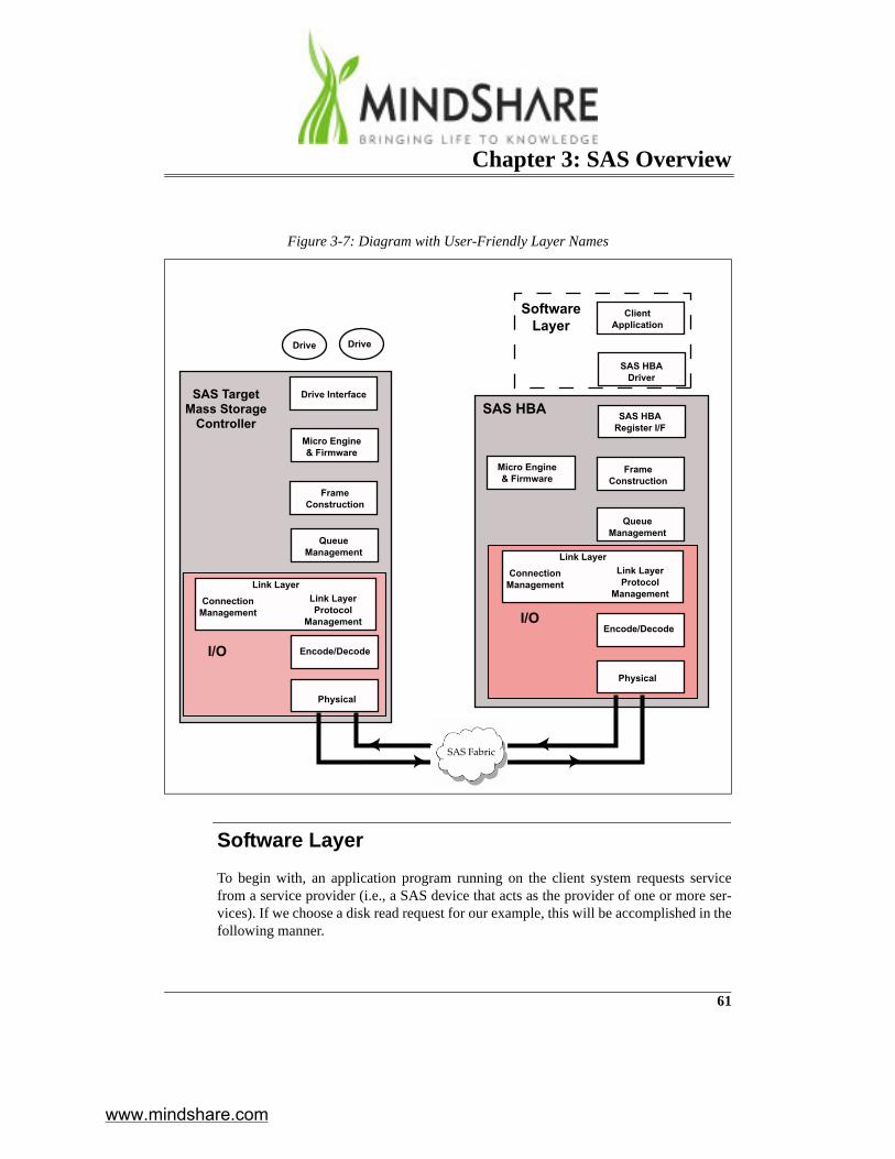
To connect with another device in order to exchange frames, SAS devices must executeseveral steps. The responsibility for implementing the logic necessary to perform thosesteps is split into smaller, more manageable parts called layers in the standard. Since thenaming and function of the SAS layers has proven to be confusing to otherwise veryintelligent people, the author has taken the liberty of giving the layers some “user-friendly” names for this introduction that more intuitively state what they do. The actuallayer names are defined at the end of this section and are then used throughout theremainder of the book.
Consider the very simple case shown in Figure 3-7, where a SAS HBA is connected to atarget device through a SAS fabric. The fabric could be any legal SAS topology, includ-ing several expanders between these two devices, but those details are not important atthis point in the discussion. The steps that take place in the communication between thetwo devices are described in the sections that follow.
www.mindshare.com
Chapter 3: SAS Overview
61
Software Layer
To begin with, an application program running on the client system requests servicefrom a service provider (i.e., a SAS device that acts as the provider of one or more ser-vices). If we choose a disk read request for our example, this will be accomplished in thefollowing manner.
Figure 3-7: Diagram with User-Friendly Layer Names
ClientApplication
SAS HBADriver
Drive Interface
SAS HBARegister I/F
Micro Engine& Firmware
Micro Engine& Firmware
FrameConstruction
FrameConstruction
QueueManagement
QueueManagement
Encode/Decode
Encode/Decode
Physical
Physical
SAS HBA
Drive Drive
SAS TargetMass Storage
Controller
I/O
I/O
Link LayerProtocol
Management
ConnectionManagement
Link Layer
Link LayerProtocol
Management
ConnectionManagement
Link Layer
SAS Fabric
SoftwareLayer
www.mindshare.com

SAS Storage Architecture
62
1. The client application (e.g., a database program) issues a request to the memoryallocator within the OS (i.e., malloc) requesting the allocation of three buffers inmemory:
a) A buffer in which the application will write a Command Descriptor Block (i.e.,a data structure) defining the operation to be performed.
b) A buffer into which the HBA will write the requested read data when it isreceived from the target.
c) A buffer into which the HBA will write the completion status when it isreceived from the target device.
2. The application then writes the CDB into the first buffer. The CDB contents definethe 64-bit address of the target disk controller, the specific LUN (logical unit num-ber) attached to that controller, the start and end logical block numbers on thatdrive, the start memory address into which the read data should be written by theHBA when it is received by the HBA, the start memory address of the memorybuffer into which the HBA will write the completion status when it is received fromthe target device and the command (in this case, it's a Disk Read operation).
3. The application calls the HBA driver and gives it the start address of the three buff-ers.
4. The driver writes those three parameters into the HBA's register set.5. The HBA reads the CDB data structure from memory.6. The HBA determines that one of its ports has a path to the target address.
Frame Construction
Under the guidance of the firmware executed by the HBA's microcontroller, the FrameConstruction Layer creates a properly-formatted command packet called a Frame.Frames consist of groups of four bytes called dwords. The term dword is short for dou-ble-word, the Intel nomenclature for a 4-byte value. After bytes go through the encodingprocess, they are referred to as characters, and Figure 3-8 shows a dword made up of 4characters. The characters are classified as one of two types, either control characters(labeled with a K in the nomenclature) or data characters (labeled with a D). The com-pleted Frame will be forwarded to the queue management level.
www.mindshare.com

Chapter 3: SAS Overview
63
Queue Management
At this level, outgoing frames are pooled into groups based on the destination addressfor which they are intended. When frames for a given address begin to arrive and getqueued up, this layer sends a request to the Link Layer within an I/O block to open aconnection to the destination device.
Link Layer
Connection Management Creates Open Request Frame
If the I/O block is not already busy managing an existing connection, the ConnectionManagement logic creates a special frame (i.e. a packet) that requests a connection beopened, and forwards it to the Encode/Decode block. Recall that the connection requestestablishes a connection between the HBA and the target device. The request consists ofan Open Request Frame that is routed by address to the target device. When the targetdevice returns a response the hardware allocates the necessary resources to establish thededicated connection.
Protocol Management
The Open Request frame is subject to the Link Layer Protocol Management logic. Partof the protocol management involves the creation of primitives that perform specialfunctions such as signifying the beginning and end of each Frame. Most of these primi-tives are generated by the Link Layer of the sender and consumed by the Link Layer ofthe receiver.
Figure 3-8: Dword
characterfirs t second third fourth
character character character
www.mindshare.com

SAS Storage Architecture
64
Primitives are easily recognized because they have a special control character in the firstbyte position (known as a control character), as shown in Figure 3-9, which illustratesboth SAS and SATA primitives. For more details on primitives see the section called“Primitives” on page 284. The next step in the process is delivering the Open Requestframe to the Encode/Decode block.
Encode/Decode Layer
In the Encode/Decode block various actions are taken to prepare the OPEN addressframe for serial transmission. These steps are common to many serial transports, includ-ing 8b/10b encoding and bit-serializing of the frame.
Physical Layer
Finally, the serialized OPEN request frame arrives at the lowest layer, called the Physi-cal Layer, where the electrical input and output buffers and transceivers reside. Here thebits are converted to the high-speed differential output and sent out across a cable orbackplane.
OPEN Request and Response
When the OPEN request is transmitted to the neighboring device (see Figure 3-10), thehigh-speed bit sequence is presented to the receiver in the neighbor's Physical Layer.The incoming differential signal is used to recreate the transmitted bit stream, which isthen presented to the Encode/Decode logic. At this level the logic decodes the data to
Figure 3-9: Primitives
K28.5 Dxx.y Dxx.y Dxx.yK28.5 Dxx.y Dxx.y Dxx.yfirs t second third fourth
K28.3 Dxx.y Dxx.y Dxx.yK28.3 Dxx.y Dxx.y Dxx.y
K28.6 Dxx.y Dxx.y Dxx.yK28.6 Dxx.y Dxx.y Dxx.y
SAS Primitive
SATA Primitive
SATA Error Primitive
www.mindshare.com

Chapter 3: SAS Overview
65
recover the original dword stream and then forwards it up to the Connection Manage-ment logic. There, the recovered information is evaluated and determined to be a requestto open a connection to the port on the target device. If the mass storage controller'supper layers have enabled it and if the requester is recognized as having permission toseek a connection with this device, then the Connection Management logic accepts theconnection request and sends an ACCEPT primitive back to the requester.
Accept Response Primitive Generated
The Connection Management layer creates an ACCEPT primitive and forwards it to the
Figure 3-10: OPEN Frame and Response
ClientApplication
SAS HBADriver
Drive Interface
SAS HBARegister I/F
Micro Engine& Firmware
Micro Engine& Firmware
FrameConstruction
FrameConstruction
QueueManagement
QueueManagement
Encode/Decode
Encode/Decode
Physical
Physical
SAS HBA
Drive Drive
SAS TargetMass Storage
Controller
I/O
I/O
Link LayerProtocol
Management
ConnectionManagement
Link Layer
Link LayerProtocol
Management
ConnectionManagement
Link Layer
OPEN frame
ACCEPT
SAS Fabric
www.mindshare.com

SAS Storage Architecture
66
Encode/Decode logic. That layer encodes and serializes the data before passing it to thePhysical Layer. The Physical Layer transmits the bit stream using its high-speed differ-ential transmitter.
When this response arrives at the Connection Management logic in the HBA, a nexusbetween the two ports has been created. The nexus information can contain up to fourparts, depending on the type of connection:
• Initiator port (I) • Target port (T)• The selected LUN (L) • The tag of the task to be executed (labeled as Q because it’s part of a Queued set of
tasks)
A nexus that uses all four is described as an I_T_L_Q nexus, which means it stores theaddresses of the initiator and target device, the LUN and the tag. This information issaved by both devices. In recognition that the OPEN request has been accepted, theConnection Management logic in the HBA reports to its Queue Management block thata connection to the intended destination is now open and ready for business.
Connection Is Established
At this point, the HBA is ready to forward the frame(s) currently queued up in theQueue Management block to the I/O block for transmission. Once the connection isestablished, whatever topology exists between the two devices has now become trans-parent and it appears to them that they have a dedicated wire between them (as illus-trated in Figure 3-11). At this point, the two devices can send as many frames as theylike within their timeout period on the bus.
This discussion began with an initiator having a request to send, but it's worth notingthat the target device could also have data ready to transmit that is associated with a pre-vious command. Since the SAS link is bidirectional, the target could use the newly-opened connection to send those data frames at the same time that it is receiving a newcommand.
www.mindshare.com

Chapter 3: SAS Overview
67
Frames Travel Connected Path (They’re Not Routed)
The frames sent within a connection do not experience any “routing” per se, becausedetermining the path from the source device to the destination device was already donewhen the connection was opened. Instead, they flow from source to destination throughwhat is now a dedicated circuit.
The frames themselves do include a hashed version of the source and destinationaddress, leading to some confusion that perhaps these addresses are used to route the
Figure 3-11: Connection Establishes a Dedicated Path Between Devices
ClientApplication
SAS HBADriver
Drive Interface
SAS HBARegister I/F
Micro Engine& Firmware
Micro Engine& Firmware
FrameConstruction
FrameConstruction
QueueManagement
QueueManagement
Encode/Decode
Encode/Decode
Physical
Physical
SAS HBA
Drive Drive
SAS TargetMass Storage
Controller
I/O
I/O
Link LayerProtocol
Management
ConnectionManagement
Link Layer
Link LayerProtocol
Management
ConnectionManagement
Link Layer
Virtual-Wire Connection
www.mindshare.com

SAS Storage Architecture
68
packets themselves, but that is not the case. In fact, the hashing function that’s used toreduce the address from 64 bits to just 24 bits causes some loss of information, so it isnot a reliable version of the addresses anyway. Instead, hashed addresses are only pro-vided for the simple reason that the space for a small destination and source addressalready existed in the header format that was borrowed from Fibre Channel (FibreChannel uses 24-bit addresses and does provide for packet routing). Since the bits werealready in the header, some vendors lobbied to have the addresses used in this way toprovide an opportunity for devices in the connection path to verify that the frames flow-ing through it are in fact using the same destination address that was used to establishthe connection. This verification cannot be made with complete confidence, though,because of the loss of information during the hashing process, so it is not expected thatmany devices will do this checking.
To summarize, the hashed addresses in the frame header are not used for routing, butonly provided as a “courtesy” for those devices that are designed to verify addressesduring a connection.
Connection Maintenance
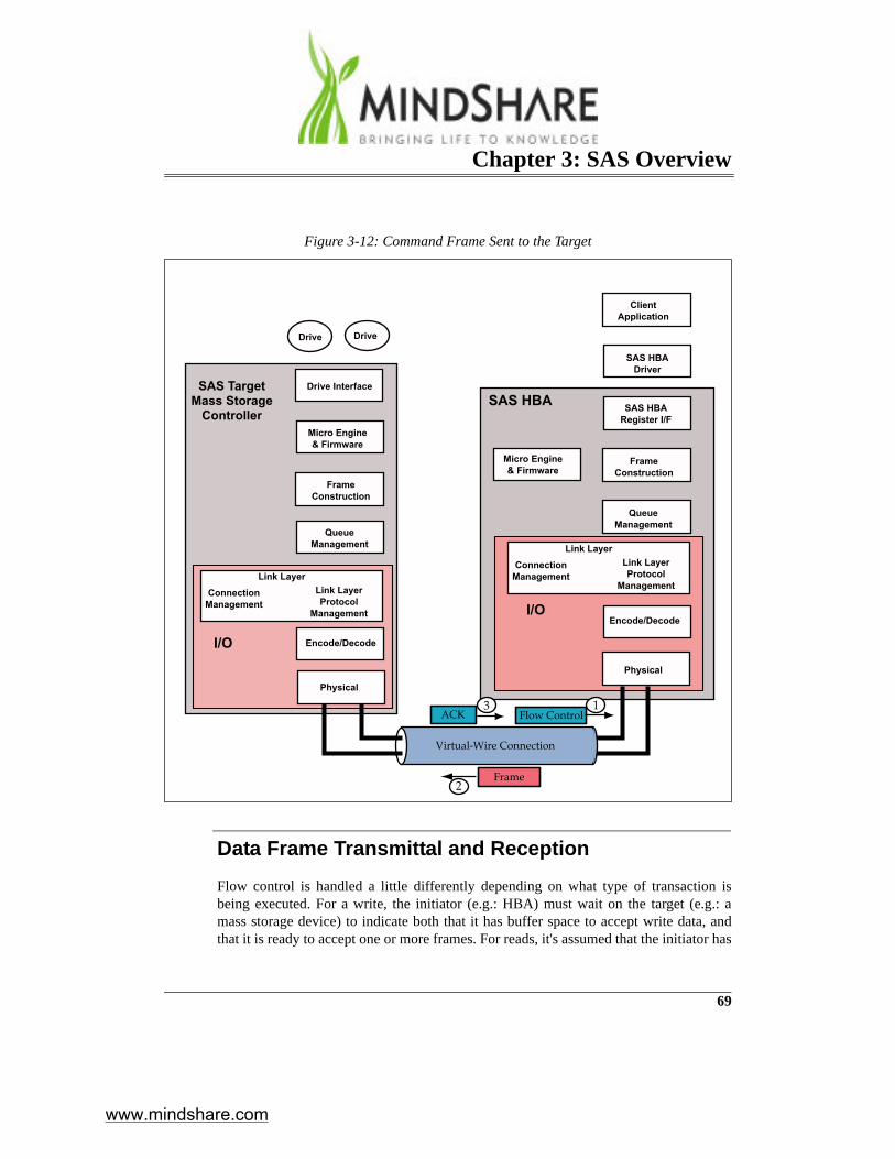
Continuing the example scenario, the Connection Management logic in the HBAinforms the Queue Management block that the connection is ready for use and the firstof the queued data frames (in this case, the disk read command frame) is forwarded backto the I/O block (see Figure 3-12 on page 69). The role of connection managementchanges now, from establishing the connection to maintaining it. Basically, that involvesthe use of two mechanisms:
• Flow control which is the means by which the receiver indicates that it has bufferspace available to receive a frame. With the one exception of the “first burst” case,in which the system is designed to guarantee a minimum receive buffer space forthe first write data before any flow control is sent, outgoing frames must await thispermission before they can be sent.
• Acknowledging safe arrival of frames at the receiver. Most frames are interlocked,meaning they must await the successful acknowledgement of the previous frame'sreception before they may be transmitted. In our example, no previous data frameshave been sent, so no acknowledgement is needed.
www.mindshare.com
Chapter 3: SAS Overview
69
Data Frame Transmittal and Reception
Flow control is handled a little differently depending on what type of transaction isbeing executed. For a write, the initiator (e.g.: HBA) must wait on the target (e.g.: amass storage device) to indicate both that it has buffer space to accept write data, andthat it is ready to accept one or more frames. For reads, it's assumed that the initiator has
Figure 3-12: Command Frame Sent to the Target
ClientApplication
SAS HBADriver
Drive Interface
SAS HBARegister I/F
Micro Engine& Firmware
Micro Engine& Firmware
FrameConstruction
FrameConstruction
QueueManagement
QueueManagement
Encode/Decode
Encode/Decode
Physical
Physical
SAS HBA
Drive Drive
SAS TargetMass Storage
Controller
I/O
I/O
Link LayerProtocol
Management
ConnectionManagement
Link Layer
Link LayerProtocol
Management
ConnectionManagement
Link Layer
Virtual-Wire Connection
Frame
Flow ControlACK
2
13
www.mindshare.com

SAS Storage Architecture
70
allocated the necessary buffer space before sending the command and the only flowcontrol needed is an indication of readiness to accept frames. For our example, once theHBA sends a flow control frame indicating that it's ready for data frames, these condi-tions are satisfied. This flow control information is only generated and used by the con-nection management logic within the initiator and target Phys, and is transparent to thehigher layers.
Once flow control verifies sufficient buffer space exists, the HBA's Connection Man-agement logic signals the Queue Management block that it's time to drain one frame outof the queue and forward it to the I/O block for transmission. As the frame is beingloaded into the Encode/Decode logic, the connection management layer adds an SOF(Start of Frame) primitive at the beginning of the frame and an EOF (End of Frame)primitive at the end to give a frame context to the receiver. At that point, the frame issent through the Encode/Decode block and Physical Layer buffers and is transmittedserially over the wire (as illustrated in Figure 3-12 on page 69).
When the data frame containing the command arrives at the target mass storage control-ler and passes through the physical buffers and Encode/Decode block, its integrity ischecked by the Connection Management block by verifying that the CRC is good,meaning there have been no changes to the bits during transmission. If there are noerrors within the frame, it is passed up to the Queue Management block and an acknowl-edge (ACK) primitive is sent back to the HBA acknowledging that the frame arrivedsafely. If there had been a problem, the frame would have been discarded and a negativeacknowledgement (NAK) sent instead. The frame is next passed up to the Frame Con-struction block, where the target's microcontroller, under the guidance of its firmware,disassembles the frame and determines that is a disk read targeting one of the LUNs(Logical Unit Numbers) attached to this controller.
The Disk Read Operation
It is fairly likely that the disk read will require a repositioning of the drive's read/writehead assembly and this mechanical action will take a long time compared to the frametransmission. In that case, the target SAS mass storage controller device would likelychoose to close the connection rather than leaving it open and preventing other devicesfrom being able to use the connection resources during that time. For simplicity, how-ever, let’s assume that the device is able to fetch the data quickly (perhaps from a read-ahead cache within the controller, for example).
www.mindshare.com

Chapter 3: SAS Overview
71
The Read Data Is Returned in a Data Frame
The first block of read data is placed in a data frame and is transmitted back to the HBA.The header of the data frame includes the context for this transaction, including theamount of data and the tag associated with the command that resulted in this data.
The HBA Processes the First Read Data Frame
Upon reception, the HBA's firmware-based microcontroller looks up the start address ofthe data buffer in system memory based on the tag value, and writes the read data tomemory. It decrements the overall read data transfer count, but the transfer count hasn'tyet been exhausted. The memory address pointer is updated to point to the next avail-able location in the memory data buffer.
The Final Read Data Frame Is Returned and Pro-cessed
The target mass storage controller continues to read data from the target LUN, pack-etizes the data into frames and sends them back to the HBA. The HBA continues towrite the returned read data to memory until the final frame is returned and the transfercount is exhausted.
The Connection Is Closed
Finally, the last step for the two devices is to close the connection. The HBA's Connec-tion Management logic causes a DONE primitive to be transmitted to the target port onthe mass storage controller. Upon receipt of the DONE, the Connection Managementlogic in the mass storage controller causes a matching DONE to be transmitted back tothe HBA. Upon receipt of DONE, the HBA's Connection Management logic sends aCLOSE primitive. The target also sends a CLOSE, because the devices don’t have towait for CLOSE before they send it. Once the devices have both sent and receivedCLOSE, the resources are released and become available for other connections.
Completion Status Is Written to Memory
The HBA's firmware-guided microcontroller causes the disk read operation's comple-
www.mindshare.com

SAS Storage Architecture
72
tion status to be written into the system memory buffer using the stored memory addresspointer.
The Client Application Is Notified
The HBA's firmware-guided microcontroller then generates an interrupt to the host sys-tem processor, causing the processor to execute the interrupt handler within the HBADevice Driver. The handler reads a status register within the handler and determines thata completion notification has been deposited in memory. The driver reads this informa-tion and, using an application ID stored with the status completion notice, it contacts theclient application program and informs it that the requested read data has successfullybeen deposited in memory. The application then consumes (i.e., uses) the data.
Summarizing the Sequence
To summarize the sequence of the frames and primitives that are exchanged in this pro-cess, consider the ladder diagram shown in Figure 3-13. Here the connection has alreadybeen established and now the flow control aspect of the connection is illustrated. If theconnection was opened by the initiator, the first thing that needs to happen is that the tar-get needs to send at least one flow control credit to the initiator so it can receive thecommand frame. This is done by sending an RRDY (Receiver Ready) primitive. Severalof these can be sent to tell the initiator that several buffers are available for data transfer,but in this example, only the one is needed. (for more on this topic, see “Flow Control”on page 346). In response, the initiator sends the command and follows that with severalRRDY primitives to indicate a readiness to accept several frames coming back.
www.mindshare.com

Chapter 3: SAS Overview
73
The target responds to the read request and the indications of available buffer space inthe initiator by sending data frames. If the read was asking for 4KB of data, as shown inthe example, the target would need to send at least 4 data frames to complete the trans-fer, because each of them can only be 1KB at most for SSP. Once all the data has beenreceived, the initiator would expect to receive a response frame from the target, report-ing on the status of the operation. That would require permission, in the form of anRRDY, so one more must be sent before the response frame can be expected.
Example Scenario — Disk Write RequestA similar case is shown in Figure 3-14, but this time the command is a write. As before,the connection is already open, so what is shown here are the command and data frames,along with the flow control exchange. Like the read example, a frame can’t be sentunless an RRDY was first received to give it permission to be sent. The difference inthis example is that the target has one more frame type it sends: the XFER_RDY frame.
Figure 3-13: SSP Read Request Example
RRDY (4x)
Command(Read 4KB)
RRDY (Rx Ready)
Data Frame (2x)
Response FrameRRDY Data Frame (2x)
time time
Initiator Target
www.mindshare.com

SAS Storage Architecture
74
Each RRDY primitive sent indicates that the receiver can accept one frame, whichmeans it must have a 1KB frame buffer available since the frame could legally be thatlarge. The XFER_RDY frame is used to report how much overall buffer space is avail-able in the target to accept write data from the initiator.
This information does seem to overlap a little, but the initiator cannot begin to send thewrite data until it receives an XFER_RDY specifying that at least part of the neededspace is available. The reason this information is not needed for the read command isbecause the initiator is expected to have sufficient buffer space available before sendingthe request, so that should never be an issue. This example is described in detail in“Flow Control” on page 346.
Figure 3-14: SSP Write Request Example
XFER_RDY(data length = 2KB)
RRDYCommand(Write 4KB)
RRDY (2x)
RRDY
Data Frame (x2)
XFER_RDY(data length = 2KB)
RRDY (2x)Data Frame (x2)
RRDYResponse Frame
Initiator Target
RRDY
timetime
www.mindshare.com
Chapter 3: SAS Overview
75
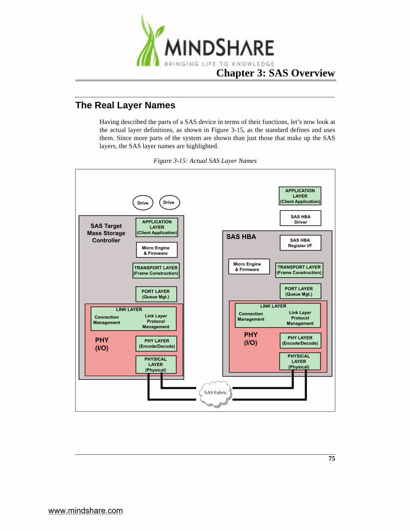
The Real Layer NamesHaving described the parts of a SAS device in terms of their functions, let’s now look atthe actual layer definitions, as shown in Figure 3-15, as the standard defines and usesthem. Since more parts of the system are shown than just those that make up the SASlayers, the SAS layer names are highlighted.
Figure 3-15: Actual SAS Layer Names
APPLICATIONLAYER
(Client Application)
SAS HBADriver
SAS HBARegister I/F
Micro Engine& Firmware
Micro Engine& Firmware
TRANSPORT LAYER(Frame Construction)
PORT LAYER(Queue Mgt.)
PHY LAYER(Encode/Decode)
PHYSICALLAYER
(Physical)
SAS HBA
Drive Drive
SAS TargetMass Storage
Controller
PHY(I/O)
Link LayerProtocol
Management
ConnectionManagement
LINK LAYER
Link LayerProtocol
Management
ConnectionManagement
LINK LAYER
SAS Fabric
PHY LAYER(Encode/Decode)
PHYSICALLAYER
(Physical)
TRANSPORT LAYER(Frame Construction)
PORT LAYER(Queue Mgt.)
APPLICATIONLAYER
(Client Application)
PHY(I/O)
www.mindshare.com

SAS Storage Architecture
76
Application Layer
Starting at the top, the official name for the software layer is the Application Layer. Forthis layer the standard defines just the changes that were made to the SCSI mode and logpages in support of the serial interface. These pages provide configuration informationabout the devices, including control parameters and status, just as they do for SCSIdevices. This layer translates the command from the device driver into the procedurecall format that SCSI uses and passes that to the next layer.
Transport Layer
The logic that performs the frame construction function is called the Transport Layer. Inessence, it receives outgoing procedure calls from the Application Layer and repackagesthe various arguments into the frame format that will be used for serial transmission.When the frame is ready it’s forwarded down to the next layer. For incoming packets itreverses the processes by parsing the frame contents and assembling a procedure call tosend to the Application Layer.
Port Layer
The next layer is the Port Layer, and it performs the function of queuing the outgoingframes into pools based on the destination address and requesting a connection for them.Once a connection to that address is open, the frames are drained out to the next layer.There really is no corresponding function for incoming frames; these are simply passedup to the Transport Layer.
Link Layer
Next is the Phy, consisting of three layers. The first of these layers is the Link Layer,which performs the function of connection management as described before. It receivesa request for a connection from the Port Layer and takes the necessary actions to estab-lish the connection on the wire. Once the connection is in place, this layer then has theresponsibility to manage it by injecting primitives into the flow as needed and verifyingflow control and acknowledgement of frames for the protocol being used. For incomingtraffic the Link Layer responds to a connection request by accepting or rejecting it and,if accepted, it manages the connection operation in the same way as before.
www.mindshare.com

Chapter 3: SAS Overview
77
Phy Layer
The next level is the Phy Layer and there’s no doubt the nomenclature gets a little con-fusing at this point. That’s one reason the layers were introduced with functional namesinstead of the names the standard uses. The Phy Layer resides within a block called thephy, and implements the Encode/Decode functions for sending and receiving theframes.
Physical Layer
At the lowest level of the hierarchy are the high-speed analog buffers that perform thedifferential signaling onto the transmission medium. For this layer, the standard definesboth the electrical characteristics of the buffers and the signaling environments theydrive.
www.mindshare.com

training that fi ts your needsMindShare recognizes and addresses your company’s technical training issues with:
• Scalable cost training • Customizable training options • Reducing time away from work• Just-in-time training • Overview and advanced topic courses • Training delivered effectively globally• Training in a classroom, at your cubicle or home offi ce • Concurrently delivered multiple-site training
bringing lifeto knowledge. real-world tech training put into practice worldwide real-world tech training put into practice worldwide real-world tech training put into practice worldwide real-world tech training put into practice worldwide
Are your company’s technical training needs being addressed in the most effective manner?
MindShare has over 25 years experience in conducting technical training on cutting-edge technologies. We understand the challenges companies have when searching for quality, effective training which reduces the students’ time away from work and provides cost-effective alternatives. MindShare offers many fl exible solutions to meet those needs. Our courses are taught by highly-skilled, enthusiastic, knowledgeable and experienced instructors. We bring life to knowledge through a wide variety of learning methods and delivery options.
2 PCI Express 2.0 ®
2 Intel Core 2 Processor Architecture
2 AMD Opteron Processor Architecture
2 Intel 64 and IA-32 Software Architecture
2 Intel PC and Chipset Architecture
2 PC Virtualization
2 USB 2.0
2 Wireless USB
2 Serial ATA (SATA)
2 Serial Attached SCSI (SAS)
2 DDR2/DDR3 DRAM Technology
2 PC BIOS Firmware
2 High-Speed Design
2 Windows Internals and Drivers
2 Linux Fundamentals
... and many more.
All courses can be customized to meet your group’s needs. Detailed course outlines can be found at www.mindshare.com
world-class technical training
MindShare training courses expand your technical skillset
*PCI Express ® is a registered trademark of the PCISIG*PCI Express ® is a registered trademark of the PCISIG
www.mindshare.com

www.mindshare.com 4285 SLASH PINE DRIVE COLORADO SPRINGS, CO 80908 USA M 1.602.617.1123 O 1.800.633.1440 [email protected]
Engage MindShareHave knowledge that you want to bring to life? MindShare will work with you to “Bring Your Knowledge to Life.” Engage us to transform your knowledge and design courses that can be delivered in classroom or virtual class-room settings, create online eLearning modules, or publish a book that you author.
We are proud to be the preferred training provider at an extensive list of clients that include:ADAPTEC • AMD • AGILENT TECHNOLOGIES • APPLE • BROADCOM • CADENCE • CRAY • CISCO • DELL • FREESCALE
GENERAL DYNAMICS • HP • IBM • KODAK • LSI LOGIC • MOTOROLA • MICROSOFT • NASA • NATIONAL SEMICONDUCTOR
NETAPP • NOKIA • NVIDIA • PLX TECHNOLOGY • QLOGIC • SIEMENS • SUN MICROSYSTEMS SYNOPSYS • TI • UNISYS
Classroom Training
Invite MindShare to train you in-house, or sign-up to attend one of our many public classes held throughout the year and around the world. No more boring classes, the ‘MindShare Experience‘ issure to keep you engaged.
Virtual Classroom Training
The majority of our courses live over the web in an inter-active environment with WebEx and a phone bridge. We deliver training cost-effectively across multiple sites and time zones. Imagine being trained in your cubicle or home offi ce and avoiding the hassle of travel. Contact us to attend one of our public virtual classes.
eLearning Module Training
MindShare is also an eLearning company. Our growing list of interactive eLearning modules include:
• Intro to Virtualization Technology
• Intro to IO Virtualization
• Intro to PCI Express 2.0 Updates
• PCI Express 2.0
• USB 2.0
• AMD Opteron Processor Architecture
• Virtualization Technology ...and more
MindShare Press
Purchase our books and eBooks or publish your own content through us. MindShare has authored over 25 books and the listis growing. Let us help make your book project a successful one.
MindShare Learning Options
MindShare Classroom
MindShare Virtual Classroom
MindShare eLearning
MindShare Press
In-House Training
Public Training
Virtual In-House Training
Virtual Public Training
Intro eLearning Modules
Comprehensive eLearning Modules
Books
eBooks
www.mindshare.com