
sarvicef1027
313
Model R-C2a/b (Machine Code: B022/B027) SERVICE MANUAL August 10th, 2001 Subject to change
Transcript of sarvicef1027

Model R-C2a/b(Machine Code: B022/B027)
SERVICE MANUAL
August 10th, 2001Subject to change
Ricoh Technical Services
For information on the B031, click in the green box

!IMPORTANT SAFETY NOTICESPREVENTION OF PHYSICAL INJURY1. Before disassembling or assembling parts of the copier and peripherals,
make sure that the copier power cord is unplugged.2. The wall outlet should be near the copier and easily accessible.3. If any adjustment or operation check has to be made with exterior covers off
or open while the main switch is turned on, keep hands away from electrifiedor mechanically driven components.
4. If a job has started before the copier completes the warm-up or initializingperiod, keep hands away from the mechanical and electrical componentsbecause the starts making copies as soon as the warm-up period iscompleted.
5. The inside and the metal parts of the fusing unit become extremely hot whilethe copier is operating. Be careful to avoid touching those components withyour bare hands.
HEALTH SAFETY CONDITIONSToner is non-toxic, but if you get it in your eyes by accident, it may causetemporary eye discomfort. Try to remove with eye drops or flush with water asfirst aid. If unsuccessful, get medical attention.
SAFETY AND ECOLOGICAL NOTES FOR DISPOSAL1. Do not incinerate the toner cassettes. Toner dust may ignite suddenly when
exposed to an open flame.2. Dispose of toner cassettes in accordance with local regulations. (This is a
non-toxic unit.)3. Dispose of replaced parts in accordance with local regulations.
OBSERVANCE OF ELECTRICAL SAFETY STANDARDS1. The copier and its peripherals must be installed and maintained by a
customer service representative who has completed the training course onthose models.
2. The NVRAM on the Controller board has a lithium battery which can explodeif replaced incorrectly. Replace the NVRAM only with an identical one. Donot recharge or burn this battery. Used NVRAM must be handled inaccordance with local regulations.
3. The danger of explosion exists if batteries on the FCU, MBU and JBIG areincorrectly replaced. Replace only with the same or an equivalent typerecommended by the manufacturer. Discard used batteries in accordancewith the manufacturer’s instructions.

LASER SAFETYThe Center for Devices and Radiological Health (CDRH) prohibits the repair oflaser-based optical units in the field. The optical housing unit can only be repairedin a factory or at a location with the requisite equipment. The laser subsystem isreplaceable in the field by a qualified Customer Engineer. The laser chassis is notrepairable in the field. Customer engineers are therefore directed to return allchassis and laser subsystems to the factory or service depot when replacement ofthe optical subsystem is required.
!WARNINGUse of controls, or adjustment, or performance of procedures other thanthose specified in this manual may result in hazardous radiation exposure.
!WARNING FOR LASER UNITWARNING: Turn off the main switch before attempting any of the
procedures in the Laser Unit section. Laser beams canseriously damage your eyes.
CAUTION MARKING:
LASER-4.WMF

i
TABLE OF CONTENTS
1 OVERALL MACHINE INFORMATION......................................... 1-11.1 SPECIFICATIONS.....................................................................................1-11.2 MACHINE CONFIGURATION...................................................................1-5
1.2.1 SYSTEM COMPONENTS ................................................................1-51.2.2 INSTALLABLE OPTION TABLE.......................................................1-7
Copier options.......................................................................................1-7Fax option .............................................................................................1-7Printer/scanner options .........................................................................1-7
1.3 PAPER PATH............................................................................................1-81.4 MECHANICAL COMPONENT LAYOUT ...................................................1-91.5 ELECTRICAL COMPONENT DESCRIPTIONS ......................................1-111.6 DRIVE LAYOUT ......................................................................................1-141.7 COPY PROCESS....................................................................................1-15
1.7.1 OVERVIEW ....................................................................................1-151.8 BOARD STRUCTURE.............................................................................1-17
1.8.1 OVERVIEW ....................................................................................1-171.8.2 CONTROLLER ...............................................................................1-19
2 DETAILED SECTION DESCRIPTIONS ....................................... 2-12.1 SCANNING................................................................................................2-1
2.1.1 OVERVIEW ......................................................................................2-12.1.2 SCANNER DRIVE ............................................................................2-22.1.3 ORIGINAL SIZE DETECTION IN PLATEN MODE...........................2-3
2.2 IMAGE PROCESSING ..............................................................................2-52.2.1 OVERVIEW ......................................................................................2-52.2.2 SBU (SENSOR BOARD UNIT).........................................................2-62.2.3 AUTO IMAGE DENSITY...................................................................2-72.2.4 IPU (IMAGE PROCESSING UNIT)...................................................2-8
Overview...............................................................................................2-8Image Processing Modes .....................................................................2-9Image Processing Path.......................................................................2-10Overview.............................................................................................2-10SP Modes for Each Image Processing Step .......................................2-11Text Mode...........................................................................................2-11Photo Mode ........................................................................................2-12Text/Photo Mode ................................................................................2-13Pale Mode...........................................................................................2-14Generation Copy.................................................................................2-15Auto Shading ......................................................................................2-16Pre-Filtering ........................................................................................2-16Main Scan Magnification/Reduction....................................................2-16Mirroring for ADF Mode ......................................................................2-16Characteristic Detection......................................................................2-17Filtering ...............................................................................................2-17Overview.............................................................................................2-17
ii
MTF Filter ...........................................................................................2-17Smoothing Filter..................................................................................2-17Characteristic Filter .............................................................................2-17Independent Dot Erase.......................................................................2-18Background Erase ..............................................................................2-18ID Gamma (γ) Correction ....................................................................2-18Gradation Processing .........................................................................2-18Overview.............................................................................................2-18Grayscale Processing.........................................................................2-19Binary Picture Processing...................................................................2-19Error Diffusion.....................................................................................2-19Dithering .............................................................................................2-19Line width correction...........................................................................2-19
2.2.5 VIDEO CONTROL UNIT (VCU)......................................................2-20Fine Character and Image (FCI) .........................................................2-20
2.3 LASER EXPOSURE................................................................................2-212.3.1 OVERVIEW ....................................................................................2-212.3.2 AUTO POWER CONTROL (APC)..................................................2-222.3.3 LD SAFETY SWITCH.....................................................................2-23
2.4 PHOTOCONDUCTOR UNIT (PCU) ........................................................2-242.4.1 OVERVIEW ....................................................................................2-242.4.2 DRIVE.............................................................................................2-252.4.3 NEW PCU DETECTION.................................................................2-26
2.5 DRUM CHARGE .....................................................................................2-272.5.1 OVERVIEW ....................................................................................2-272.5.1 CHARGE ROLLER VOLTAGE CORRECTION ..............................2-28
Correction for Environmental Conditions ............................................2-282.5.2 ID SENSOR PATTERN PRODUCTION TIMING............................2-292.5.3 DRUM CHARGE ROLLER CLEANING..........................................2-30
2.6 DEVELOPMENT .....................................................................................2-312.6.1 OVERVIEW ....................................................................................2-312.6.2 DRIVE.............................................................................................2-322.6.3 DEVELOPER MIXING....................................................................2-332.6.4 DEVELOPMENT BIAS ...................................................................2-342.6.5 TONER SUPPLY............................................................................2-35
Toner bottle replenishment mechanism..............................................2-35Toner supply mechanism....................................................................2-36
2.6.6 TONER DENSITY CONTROL ........................................................2-37Overview.............................................................................................2-37Toner density sensor initial setting......................................................2-39Toner density measurement ...............................................................2-39Vsp/Vsg detection...............................................................................2-39Toner supply reference voltage (Vref) determination..........................2-39Toner supply determination ................................................................2-39Toner Supply Motor On Time Determinations.....................................2-40
2.6.7 TONER SUPPLY IN ABNORMAL SENSOR CONDITIONS...........2-41ID sensor ............................................................................................2-41TD Sensor...........................................................................................2-41
2.6.8 TONER NEAR END/END DETECTION AND RECOVERY............2-41
iii
Toner Near End Detection ..................................................................2-41Toner Near End Recovery ..................................................................2-42Toner End Detection...........................................................................2-42Toner End Recovery ...........................................................................2-42
2.7 DRUM CLEANING AND TONER RECYCLING.......................................2-432.7.1 DRUM CLEANING..........................................................................2-432.7.2 TONER RECYCLING .....................................................................2-44
2.8 PAPER FEED..........................................................................................2-452.8.1 OVERVIEW ....................................................................................2-452.8.2 PAPER FEED DRIVE MECHANISM ..............................................2-462.8.3 PAPER FEED AND SEPARATION MECHANISM .........................2-472.8.4 PAPER LIFT MECHANISM ............................................................2-482.8.5 PAPER END DETECTION .............................................................2-492.8.6 PAPER HEIGHT DETECTION .......................................................2-502.8.7 FEED PRESSURE ADJUSTMENT FOR PAPER SIZE..................2-51
Overview.............................................................................................2-51Paper Size Thresholds........................................................................2-51Feed Pressure Adjustment .................................................................2-52Effect of the Amount of Remaining Paper...........................................2-52From tray full to paper near-end .........................................................2-52From paper near end to paper end .....................................................2-53
2.8.8 PAPER SIZE DETECTION.............................................................2-542.8.9 SPECIAL PAPER SETTING...........................................................2-552.8.10 SIDE AND END FENCES.............................................................2-56
Side Fences........................................................................................2-56End Fence ..........................................................................................2-56
2.8.11 PAPER REGISTRATION..............................................................2-572.9 IMAGE TRANSFER AND PAPER SEPARATION...................................2-58
2.9.1 OVERVIEW ....................................................................................2-582.9.2 IMAGE TRANSFER CURRENT TIMING........................................2-592.9.3 TRANSFER ROLLER CLEANING..................................................2-602.9.4 PAPER SEPARATION MECHANISM.............................................2-60
2.10 IMAGE FUSING AND PAPER EXIT......................................................2-612.10.1 OVERVIEW ..................................................................................2-612.10.2 FUSING DRIVE AND RELEASE MECHANISM ...........................2-622.10.3 FUSING ENTRANCE GUIDE SHIFT MECHANISM.....................2-632.10.4 PRESSURE ROLLER...................................................................2-642.10.5 CLEANING MECHANISM ............................................................2-642.10.6 FUSING TEMPERATURE CONTROL..........................................2-65
Temperature Control...........................................................................2-65Fusing Lamp Control...........................................................................2-66
2.10.7 OVERHEAT PROTECTION .........................................................2-672.10.8 PAPER EXIT ................................................................................2-67
2.11 ENERGY SAVER MODES ....................................................................2-682.11.1 OVERVIEW ..................................................................................2-682.11.2 ENERGY SAVER MODE..............................................................2-69
Entering the energy saver mode.........................................................2-69What happens in energy saver mode .................................................2-69Return to stand-by mode ....................................................................2-69

iv
2.11.3 AUTO OFF MODE........................................................................2-70Entering off stand-by and off modes ...................................................2-70Off Stand-by mode..............................................................................2-70Off Mode .............................................................................................2-70Returning to stand-by mode................................................................2-70
3 INSTALLATION PROCEDURE.................................................... 3-13.1 INSTALLATION REQUIREMENTS ...........................................................3-1
3.1.1 ENVIRONMENT ...............................................................................3-13.1.2 MACHINE LEVEL.............................................................................3-13.1.3 MINIMUM SPACE REQUIREMENTS...............................................3-23.1.4 POWER REQUIREMENTS ..............................................................3-3
3.2 COPIER INSTALLATION ..........................................................................3-43.2.1 POWER SOCKETS FOR PERIPHERALS .......................................3-43.2.2 INSTALLATION FLOW CHART .......................................................3-53.2.3 ACCESSORY CHECK......................................................................3-63.2.4 INSTALLATION PROCEDURE ........................................................3-7
3.3 PAPER TRAY UNIT INSTALLATION......................................................3-113.3.1 ACCESSORY CHECK....................................................................3-113.3.2 INSTALLATION PROCEDURE ......................................................3-11
3.4 LCT INSTALLATION ...............................................................................3-143.4.1 ACCESSORY CHECK....................................................................3-143.4.2 INSTALLATION PROCEDURE ......................................................3-14
3.5 AUTO REVERSE DOCUMENT FEEDER INSTALLATION.....................3-173.5.1 ACCESSORY CHECK....................................................................3-173.5.2 INSTALLATION PROCEDURE ......................................................3-17
3.6 INTERCHANGE UNIT INSTALLATION...................................................3-203.6.1 COMPONENT CHECK...................................................................3-203.6.2 INSTALLATION PROCEDURE ......................................................3-21
3.7 1-BIN TRAY UNIT INSTALLATION.........................................................3-233.7.1 COMPONENT CHECK...................................................................3-233.7.2 INSTALLATION PROCEDURE ......................................................3-23
3.8 SHIFT TRAY............................................................................................3-263.8.1 COMPONENT CHECK...................................................................3-263.8.2 INSTALLATION PROCEDURE ......................................................3-26
3.9 BY-PASS FEED UNIT INSTALLATION...................................................3-283.9.1 COMPONENTS CHECK ................................................................3-283.9.2 INSTALLATION PROCEDURE ......................................................3-28
3.10 DUPLEX UNIT INSTALLATION ............................................................3-303.10.1 ACCESSORY CHECK..................................................................3-303.10.2 INSTALLATION PROCEDURE ....................................................3-31
3.11 BRIDGE UNIT INSTALLATION.............................................................3-333.11.1 ACCESSORY CHECK..................................................................3-333.11.2 INSTALLATION PROCEDURE ....................................................3-33
3.12 1,000-SHEET FINISHER INSTALLATION ............................................3-353.12.1 ACCESSORY CHECK..................................................................3-353.12.2 INSTALLATION PROCEDURE ....................................................3-36
3.13 500-SHEET FINISHER INSTALLATION ...............................................3-393.13.1 ACCESSORY CHECK..................................................................3-39
v
3.13.2 INSTALLATION PROCEDURE ....................................................3-403.14 PLATEN COVER INSTALLATION ........................................................3-42
3.14.1 MEMORY (G578/G579)................................................................3-433.14.2 HDD (B420) ..................................................................................3-44
3.15 KEY COUNTER INSTALLATION ..........................................................3-463.16 ANTI-CONDENSATION HEATER.........................................................3-483.17 TRAY HEATER .....................................................................................3-493.18 TRAY HEATER (OPTIONAL PAPER TRAY UNIT) ...............................3-513.19 TRAY HEATER (OPTIONAL LCT) ........................................................3-54
4 SERVICE TABLES....................................................................... 4-14.1 GENERAL CAUTION ................................................................................4-1
4.1.1 PCU (PHOTOCONDUCTOR UNIT) .................................................4-14.1.2 TRANSFER ROLLER UNIT..............................................................4-14.1.3 SCANNER UNIT...............................................................................4-14.1.4 LASER UNIT ....................................................................................4-24.1.5 FUSING UNIT...................................................................................4-24.1.6 PAPER FEED...................................................................................4-24.1.7 OTHERS...........................................................................................4-2
4.2 SERVICE PROGRAM MODE....................................................................4-34.2.1 SERVICE PROGRAM MODE OPERATION.....................................4-3
Entering and Exiting SP mode ..............................................................4-3SP Mode Button Summary ...................................................................4-4Switching Between SP Mode and Copy Mode for Test Printing ...........4-5Selecting the Program Number.............................................................4-5
4.2.2 SERVICE PROGRAM MODE TABLES............................................4-6SP1-XXX: Feed ....................................................................................4-6SP2-XXX: Drum..................................................................................4-16SP4-XXX: Scanner .............................................................................4-25SP5-XXX: Mode..................................................................................4-31SP6-XXX: Peripherals.........................................................................4-41SP7-XXX: Data Log ............................................................................4-43SP9-XXX: Debug/Testing ...................................................................4-52
4.2.3 TEST PATTERN PRINTING (SP2-902-3) ......................................4-534.2.4 INPUT CHECK ...............................................................................4-54
Main Machine Input Check (SP5-803) ................................................4-54ARDF Input Check (SP6-007).............................................................4-57Finisher Input Check (SP6-117)..........................................................4-58
4.2.5 OUTPUT CHECK ...........................................................................4-60Main Machine Output Check (SP5-804) .............................................4-60ARDF Output Check (SP6-008)..........................................................4-62Finisher Output Check (SP6-118).......................................................4-62
4.2.6 SMC DATA LISTS (SP5-990).........................................................4-634.2.7 MEMORY ALL CLEAR (SP5-801)..................................................4-64
Using a Flash Memory Card ...............................................................4-64Without Using a Flash Memory Card ..................................................4-65
4.2.8 UPLOADING/DOWNLOADING NVRAM DATA..............................4-66Uploading NVRAM Data (SP5-824)....................................................4-66Downloading NVRAM Data (SP5-825) ...............................................4-67

vi
4.2.9 APS OUTPUT DISPLAY (SP4-301) ...............................................4-684.2.10 DF APS SENSOR OUTPUT DISPLAY (SP6-901)........................4-694.2.11 NIP BAND WIDTH MEASUREMENT (SP1-109)..........................4-70
4.3 PROGRAM DOWNLOAD........................................................................4-714.4 SOFTWARE RESET ...............................................................................4-724.5 SYSTEM SETTINGS AND COPY SETTING RESET..............................4-72
4.5.1 SYSTEM SETTING RESET ...........................................................4-724.5.2 COPIER SETTING RESET ............................................................4-73
4.6 USER TOOLS .........................................................................................4-744.6.1 HOW TO USE UP MODE...............................................................4-74
UP Mode Initial Screen: User Tools/Counter Display..........................4-74System Settings..................................................................................4-74Copier/Document Server Features .....................................................4-75Printer, Facsimile, Scanner Settings...................................................4-75Inquiry .................................................................................................4-75Counter ...............................................................................................4-76
4.7 LEDS .......................................................................................................4-77Controller ............................................................................................4-77SBCU..................................................................................................4-77IPU......................................................................................................4-77
4.8 DIP SWITCHES.......................................................................................4-77Controller: DIP SW2 ...........................................................................4-77SBCU: DIP SW102 .............................................................................4-77
4.9 SPECIAL TOOLS AND LUBRICANTS ....................................................4-784.9.1 SPECIAL TOOLS ...........................................................................4-784.9.2 LUBRICANTS.................................................................................4-78
5 PREVENTIVE MAINTENANCE SCHEDULE ............................... 5-15.1 PM TABLE.................................................................................................5-1
6 REPLACEMENT AND ADJUSTMENT......................................... 6-16.1 SCANNER UNIT........................................................................................6-1
6.1.1 EXPOSURE GLASS.........................................................................6-16.1.2 SCANNER EXTERIOR/OPERATION PANEL ..................................6-26.1.3 LENS BLOCK ASSEMBLY...............................................................6-36.1.4 ORIGINAL SIZE SENSORS .............................................................6-46.1.5 EXPOSURE LAMP...........................................................................6-56.1.6 SCANNER MOTOR/LAMP STABILIZER..........................................6-66.1.7 SCANNER WIRES ...........................................................................6-7
6.2 LASER UNIT ...........................................................................................6-106.2.1 CAUTION DECAL LOCATIONS.....................................................6-106.2.2 LASER UNIT ..................................................................................6-116.2.3 POLYGON MIRROR MOTOR ........................................................6-126.2.4 LD UNIT..........................................................................................6-126.2.5 LASER SYNCHRONIZATION DETECTOR....................................6-13
6.3 PHOTOCONDUCTOR UNIT (PCU) ........................................................6-146.3.1 PCU................................................................................................6-14
6.4 TRANSFER UNIT....................................................................................6-156.4.1 TRANSFER ROLLER UNIT............................................................6-15
vii
6.4.2 IMAGE DENSITY SENSOR ...........................................................6-166.5 FUSING/EXIT ..........................................................................................6-17
6.5.1 FUSING UNIT.................................................................................6-176.5.2 THERMISTORS .............................................................................6-176.5.3 THERMOFUSE ..............................................................................6-186.5.4 HOT ROLLER AND FUSING LAMP...............................................6-206.5.5 PRESSURE ROLLER/CLEANING ROLLER..................................6-216.5.6 PAPER EXIT SENSOR/PAPER OVERFLOW SENSOR................6-22
6.6 PAPER FEED..........................................................................................6-236.6.1 FEED ROLLERS ............................................................................6-236.6.2 PAPER END SENSOR...................................................................6-246.6.3 PAPER TRAY LIFT MOTORS........................................................6-256.6.4 REGISTRATION CLUTCH .............................................................6-266.6.5 PAPER FEED CLUTCHES.............................................................6-27
Lower Paper Feed Clutch ...................................................................6-27Upper Paper Feed Clutch. ..................................................................6-27
6.6.6 RELAY CLUTCHES........................................................................6-286.6.7 PAPER SIZE DETECTOR..............................................................6-296.6.8 REGISTRATION SENSOR.............................................................6-306.6.9 RELAY SENSORS .........................................................................6-31
Upper Relay Sensor............................................................................6-31Lower Relay Sensor............................................................................6-31
6.7 PCBS AND OTHER ITEMS.....................................................................6-326.7.1 CONTROLLER BOARD .................................................................6-326.7.2 SBCU BOARD................................................................................6-336.7.3 POWER PACK ...............................................................................6-336.7.4 MAIN MOTOR ................................................................................6-346.7.5 PSU ................................................................................................6-35
6.8 COPY ADJUSTMENTS: PRINTING/SCANNING....................................6-366.8.1 PRINTING ......................................................................................6-36
Registration - Leading Edge/Side-to-Side...........................................6-36Blank Margin.......................................................................................6-37Main Scan Magnification.....................................................................6-37Parallelogram Image Adjustment........................................................6-38
6.8.2 SCANNING.....................................................................................6-39Registration: Platen Mode...................................................................6-39Magnification.......................................................................................6-39Standard White Density Adjustment ...................................................6-40
6.8.3 ADF IMAGE ADJUSTMENT...........................................................6-41Registration.........................................................................................6-41Sub Scan Magnification ......................................................................6-41
6.8.4 TOUCH SCREEN CALIBRATION ..................................................6-42
7 TROUBLESHOOTING ................................................................. 7-17.1 SERVICE CALL CONDITIONS .................................................................7-1
7.1.1 SUMMARY .......................................................................................7-17.1.2 SC CODE DESCRIPTIONS .............................................................7-2
7.2 SELF-DIAGNOSTIC MODE ....................................................................7-127.2.1 SELF-DIAGNOSTIC MODE AT POWER ON .................................7-12
viii
7.2.2 DETAILED SELF-DIAGNOSTIC MODE.........................................7-13Executing Detailed Self-Diagnosis......................................................7-13
7.3 PAPER FEED TROUBLESHOOTING.....................................................7-157.4 SKEWED IMAGE ....................................................................................7-167.5 ELECTRICAL COMPONENT DEFECTS ................................................7-17
7.5.1 SENSORS ......................................................................................7-177.5.2 SWITCHES.....................................................................................7-19
7.6 BLOWN FUSE CONDITIONS .................................................................7-20
OPTIONS
PAPER TRAY UNIT (A860/B390)
1 OVERALL MACHINE INFORMATION...................................B390-11.1 SPECIFICATIONS.............................................................................. B390-11.2 MECHANICAL COMPONENT LAYOUT ............................................ B390-21.3 ELECTRICAL COMPONENT LAYOUT.............................................. B390-31.4 ELECTRICAL COMPONENT DESCRIPTION.................................... B390-41.5 DRIVE LAYOUT ................................................................................. B390-5
2 DETAILED DESCRIPTIONS ..................................................B390-62.1 PAPER FEED AND SEPARATION MECHANISM ............................. B390-62.2 PAPER LIFT MECHANISM ................................................................ B390-72.3 PAPER END DETECTION ................................................................. B390-92.4 PAPER HEIGHT DETECTION ......................................................... B390-102.5 PAPER SIZE DETECTION............................................................... B390-122.6 SIDE AND END FENCES ................................................................ B390-13
Side Fences................................................................................. B390-13End Fence ................................................................................... B390-13
3 REPLACEMENT AND ADJUSTMENT.................................B390-143.1 FEED ROLLER REPLACEMENT..................................................... B390-143.2 TRAY MAIN BOARD REPLACEMENT ............................................ B390-153.3 TRAY MOTOR REPLACEMENT...................................................... B390-153.4 RELAY CLUTCH REPLACEMENT .................................................. B390-163.5 UPPER PAPER FEED CLUTCH REPLACEMENT .......................... B390-173.6 LOWER PAPER FEED CLUTCH REPLACEMENT ......................... B390-183.7 LIFT MOTOR REPLACEMENT........................................................ B390-193.8 PAPER END SENSOR REPLACEMENT......................................... B390-203.9 VERTICAL TRANSPORT SENSOR REPLACEMENT ..................... B390-203.10 PAPER SIZE SWITCH REPLACEMENT ....................................... B390-21
ix
LCT (A862/B391)
1 OVERALL MACHINE INFORMATION...................................B391-11.1 SPECIFICATIONS.............................................................................. B391-11.2 MECHANICAL COMPONENT LAYOUT ............................................ B391-21.3 ELECTRICAL COMPONENT LAYOUT.............................................. B391-31.4 ELECTRICAL COMPONENT DESCRIPTIONS ................................. B391-4
2 DETAILED SECTION DESCRIPTIONS .................................B391-52.1 PAPER FEED..................................................................................... B391-52.2 REVERSE ROLLER AND PICK-UP ROLLER RELEASE .................. B391-62.3 TRAY LIFT ......................................................................................... B391-72.4 NEAR END/END DETECTION........................................................... B391-82.5 RIGHT TRAY SIDE FENCE ............................................................... B391-92.6 LEFT TRAY REAR FENCE ................................................................ B391-92.7 RIGHT TRAY PAPER END DETECTION ........................................ B391-10
3 REPLACEMENT AND ADJUSTMENT.................................B391-113.1 DETACHING THE TRAY FROM THE MAINFRAME........................ B391-113.2 REAR FENCE HP SENSOR ............................................................ B391-113.3 CHANGING THE TRAY PAPER SIZE ............................................. B391-123.4 LEFT TRAY PAPER END SENSOR ................................................ B391-123.5 TRAY LIFT MOTOR ......................................................................... B391-133.6 TRAY MOTOR.................................................................................. B391-143.7 PAPER FEED CLUTCH AND RELAY CLUTCH............................... B391-153.8 PAPER FEED UNIT ......................................................................... B391-163.9 UPPER LIMIT, RIGHT TRAY PAPER END, AND RELAY SENSORS .................................................................. B391-173.10 REAR FENCE MOTOR .................................................................. B391-183.11 PICK-UP/PAPER FEED/REVERSE ROLLERS.............................. B391-19
AUTO REVERSE DOCUMENT FEEDER (B386)
1 OVERALL MACHINE INFORMATION...................................B386-11.1 SPECIFICATIONS.............................................................................. B386-11.2 MECHANICAL COMPONENT LAYOUT ............................................ B386-21.3 ELECTRICAL COMPONENT LAYOUT.............................................. B386-31.4 ELECTRICAL COMPONENT DESCRIPTION.................................... B386-41.5 DRIVE LAYOUT ................................................................................. B386-5
2 DETAILED SECTION DESCRIPTIONS .................................B386-62.1 ORIGINAL SIZE DETECTION............................................................ B386-62.2 MIXED ORIGINAL SIZE MODE ......................................................... B386-92.3 PICK-UP AND SEPARATION .......................................................... B386-102.4 ORIGINAL TRANSPORT AND EXIT................................................ B386-11
2.4.1 SINGLE-SIDED ORIGINALS................................................... B386-11
x
2.4.2 DOUBLE-SIDED ORIGINALS ................................................. B386-122.4.3 ORIGINAL TRAILING EDGE SENSOR................................... B386-13
2.5 STAMP ............................................................................................. B386-142.6 TIMING CHART................................................................................ B386-152.7 CONDITION OF JAM DETECTION.................................................. B386-162.8 OVERALL ELECTRICAL CIRCUIT .................................................. B386-17
3 SERVICE TABLES...............................................................B386-183.1 DIP SWITCHES................................................................................ B386-18
4 REPLACEMENT AND ADJUSTMENT.................................B386-194.1 DF EXIT TABLE AND COVER ......................................................... B386-194.2 ORIGINAL FEED UNIT .................................................................... B386-204.3 LEFT COVER................................................................................... B386-214.4 PICK-UP ROLLER............................................................................ B386-224.5 FEED BELT...................................................................................... B386-234.6 SEPARATION ROLLER ................................................................... B386-244.7 ORIGINAL SET/ORIGINAL REVERSE SENSOR ............................ B386-254.8 ORIGINAL SIZE SENSOR ............................................................... B386-264.9 ORIGINAL FEED DRIVE.................................................................. B386-27
DF Feed Clutch............................................................................ B386-27Pick-up Solenoid.......................................................................... B386-27Transport Motor ........................................................................... B386-27DF Feed Motor............................................................................. B386-27
4.10 REGISTRATION SENSOR............................................................. B386-284.11 STAMP SOLENOID AND ORIGINAL EXIT SENSOR.................... B386-29
INTERCHANGE UNIT (B300/B416)
1 OVERALL MACHINE INFORMATION...................................B416-11.1 SPECIFICATIONS.............................................................................. B416-11.2 MECHANICAL COMPONENT LAYOUT ............................................ B416-21.3 DRIVE LAYOUT ................................................................................. B416-3
2 DETAILED DESCRIPTION ....................................................B416-42.1 JUNCTION GATE MECHANISM........................................................ B416-4
To the Exit Tray or Bridge Unit(for the Upper Tray on top of the Bridge Unit, or the Finisher) ....... B416-4To the 1-bin Tray............................................................................ B416-4To the Duplex Unit ......................................................................... B416-4
3 REPLACEMENT AND ADJUSTMENT...................................B416-53.1 EXIT SENSOR REPLACEMENT........................................................ B416-5

xi
1-BIN TRAY UNIT (A898/B413)
1 OVERALL INFORMATION ....................................................B413-11.1 SPECIFICATIONS.............................................................................. B413-11.2 MECHANICAL COMPONENT LAYOUT ............................................ B413-21.3 ELECTRICAL COMPONENT LAYOUT.............................................. B413-31.4 ELECTRICAL COMPONENT DESCRIPTION.................................... B413-3
2 DETAILED SECTION DESCRIPTIONS .................................B413-42.1 BASIC OPERATION........................................................................... B413-4
3 REPLACEMENT AND ADJUSTMENT...................................B413-53.1 PAPER SENSOR REMOVAL............................................................. B413-5
SHIFT TRAY UNIT (B313/B459)
1 OVERALL MACHINE INFORMATION...................................B459-11.1 SPECIFICATIONS.............................................................................. B459-11.2 COMPONENT LAYOUT..................................................................... B459-2
2 DETAILED SECTION DESCRIPTIONS .................................B459-32.1 BASIC OPERATION........................................................................... B459-32.2 PRIMARY MECHANISMS.................................................................. B459-4
2.2.1 TRAY SHIFT.............................................................................. B459-42.2.2 HALF TURN DETECTION......................................................... B459-5
3 REPLACEMENT AND ADJUSTMENT...................................B459-63.1 TRAY COVER REPLACEMENT ........................................................ B459-6
3.1.1 TRAY COVER REMOVAL......................................................... B459-63.1.2 TRAY COVER ATTACHMENT.................................................. B459-6
3.2 TRAY MOTOR AND HALF TURN SENSOR REPLACEMENT .......... B459-73.2.1 REPLACING THE TRAY MOTOR............................................. B459-73.2.2 REPLACING THE HALF TURN SENSOR:................................ B459-7
BY-PASS (A899/B415)
1 OVERALL MACHINE INFORMATION...................................B415-11.1 SPECIFICATIONS.............................................................................. B415-11.2 MECHANICAL COMPONENT LAYOUT ............................................ B415-11.3 ELECTRICAL COMPONENT LAYOUT.............................................. B415-21.4 ELECTRICAL COMPONENT DESCRIPTION.................................... B415-2
2 DETAILED DESCRIPTIONS ..................................................B415-32.1 BASIC OPERATION........................................................................... B415-3
xii
2.2 PAPER SIZE DETECTION................................................................. B415-4
3 REPLACEMENT AND ADJUSTMENT...................................B415-53.1 PAPER FEED ROLLER/FRICTION PAD/PAPER END SENSOR...... B415-53.2 PAPER SIZE SENSOR BOARD......................................................... B415-63.3 PAPER FEED CLUTCH ..................................................................... B415-7
DUPLEX (A896/B414)
1 OVERALL MACHINE INFORMATION...................................B414-11.1 SPECIFICATIONS.............................................................................. B414-11.2 MECHANICAL COMPONENT LAYOUT ............................................ B414-21.3 ELECTRICAL COMPONENT LAYOUT.............................................. B414-31.4 ELECTRICAL COMPONENT DESCRIPTION.................................... B414-41.5 DRIVE LAYOUT ................................................................................. B414-5
2 DETAILED DESCRIPTIONS ..................................................B414-62.1 BASIC OPERATION........................................................................... B414-6
Longer than A4 sideways/LT sideways.......................................... B414-6Up to A4 sideways/LT sideways .................................................... B414-7
2.2 FEED IN AND EXIT MECHANISM..................................................... B414-8When paper is fed into duplex unit:................................................ B414-8Inversion and Exit: ......................................................................... B414-8
3 REPLACEMENT AND ADJUSTMENT...................................B414-93.1 COVER REMOVAL ............................................................................ B414-93.2 ENTRANCE SENSOR REPLACEMENT.......................................... B414-103.3 EXIT SENSOR REPLACEMENT...................................................... B414-11
BRIDGE UNIT (A897/B417)
1 OVERALL MACHINE INFORMATION...................................B417-11.1 SPECIFICATIONS.............................................................................. B417-11.2 MECHANICAL COMPONENT LAYOUT ............................................ B417-21.3 ELECTRICAL COMPONENT LAYOUT.............................................. B417-31.4 ELECTRICAL COMPONENT DESCRIPTION.................................... B417-41.5 DRIVE LAYOUT ................................................................................. B417-5
2 DETAILED DESCRIPTION ....................................................B417-62.1 JUNCTION GATE MECHANISM........................................................ B417-6
3 REPLACEMENT AND ADJUSTMENT...................................B417-73.1 BRIDGE UNIT DRIVE MOTOR REPLACEMENT .............................. B417-73.2 TRAY EXIT SENSOR REPLACEMENT ............................................. B417-83.3 RELAY SENSOR REPLACEMENT.................................................... B417-8

xiii
1,000-SHEET FINISHER (B408)
1 REPLACEMENT AND ADJUSTMENT...................................B408-11.1 MAIN PCB .......................................................................................... B408-11.2 STAPLER UNIT.................................................................................. B408-21.3 MOTORS............................................................................................ B408-3
1.3.1 SHIFT MOTOR.......................................................................... B408-31.3.2 STAPLER MOTOR.................................................................... B408-31.3.3 UPPER TRANSPORT MOTOR AND EXIT MOTOR ................. B408-31.3.4 LOWER TRANSPORT MOTOR ................................................ B408-4
1.4 MOTORS AND SENSORS................................................................. B408-51.4.1 PREPARATION......................................................................... B408-51.4.2 STACK HEIGHT SENSOR........................................................ B408-61.4.3 STAPLER TRAY PAPER SENSOR........................................... B408-61.4.4 LOWER TRAY LIFT MOTOR .................................................... B408-61.4.5 STACK FEED-OUT MOTOR ..................................................... B408-7
2 TROUBLESHOOTING ...........................................................B408-82.1 JAM DETECTION............................................................................... B408-8
3 SERVICE TABLES.................................................................B408-93.1 DIP SWITCH SETTINGS ................................................................... B408-9
4 DETAILED DESCRIPTIONS ................................................B408-104.1 GENERAL LAYOUT ......................................................................... B408-104.2 ELECTRICAL COMPONENT LAYOUT............................................ B408-114.3 ELECTRICAL COMPONENT DESCRIPTION.................................. B408-134.4 DRIVE LAYOUT ............................................................................... B408-154.5 JUNCTION GATES .......................................................................... B408-17
Upper tray mode .......................................................................... B408-17Sort/stack mode........................................................................... B408-17Staple mode................................................................................. B408-17
4.6 UPPER TRAY................................................................................... B408-184.7 LOWER TRAY UP/DOWN MECHANISMS ...................................... B408-194.8 PAPER SHIFT MECHANISM ........................................................... B408-204.9 JOGGER UNIT PAPER POSITIONING MECHANISM..................... B408-214.10 EXIT GUIDE PLATE....................................................................... B408-224.11 STAPLER MECHANISM ................................................................ B408-234.12 STAPLER UNIT MOVEMENT MECHANISM ................................. B408-244.13 PAPER FEED-OUT MECHANISM ................................................. B408-25
5 OVERALL MACHINE INFORMATION.................................B408-265.1 SPECIFICATIONS............................................................................ B408-26
Upper Tray................................................................................... B408-26Lower Tray................................................................................... B408-26

xiv
500-SHEET FINISHER (G302/B442)
1 REPLACEMENT AND ADJUSTMENT...................................B442-11.1 EXTERIOR ......................................................................................... B442-11.2 ENTRANCE UPPER GUIDE / PAPER EXIT UNIT............................. B442-41.3 ENTRANCE LOWER GUIDE ............................................................. B442-51.4 PAPER EXIT UNIT GEAR / PADDLE ROLLER SOLENOID.............. B442-51.5 STAPLER UNIT.................................................................................. B442-61.6 JOGGER TRAY UNIT ........................................................................ B442-61.7 PAPER EXIT SENSOR FEELER ....................................................... B442-71.8 MAIN MOTOR .................................................................................... B442-71.9 JOGGER MOTOR.............................................................................. B442-81.10 CONTROL BOARD .......................................................................... B442-81.11 OUTPUT TRAY UNIT....................................................................... B442-9
2 DETAILED DESCRIPTIONS ................................................B442-102.1 OVERALL MACHINE INFORMATION ............................................. B442-10
2.1.1 COMPONENT LAYOUT .......................................................... B442-10Mechanical component layout ..................................................... B442-10Drive layout.................................................................................. B442-11
2.1.2 ELECTRICAL COMPONENT DESCRIPTIONS ...................... B442-122.2 DETAILED SECTION DESCRIPTIONS ........................................... B442-14
2.2.1 OUTPUT TRAY MECHANISM ................................................ B442-14Stack height detection.................................................................. B442-14Output tray up/down mechanism ................................................. B442-15
2.2.2 PAPER FEED.......................................................................... B442-16Overview...................................................................................... B442-16Straight feed out mode................................................................. B442-16Shift sorting mode........................................................................ B442-17Stapling mode.............................................................................. B442-19
2.2.3 JAM CONDITIONS.................................................................. B442-202.2.4 ERROR DETECTION.............................................................. B442-20
3 OVERALL MACHINE INFORMATION.................................B442-213.1 SPECIFICATIONS............................................................................. B442-21
10 August, 2001 SPECIFICATIONS
1-1
Ove
rall
Info
rmat
ion1. OVERALL MACHINE INFORMATION
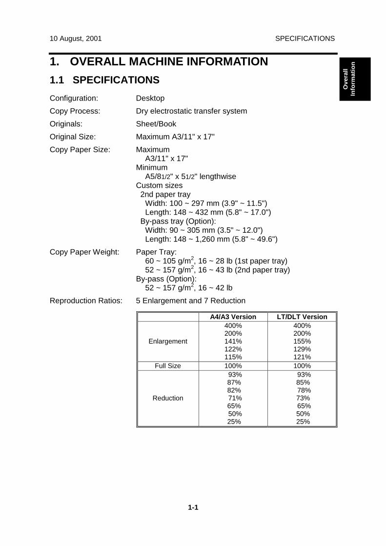
1.1 SPECIFICATIONSConfiguration: DesktopCopy Process: Dry electrostatic transfer systemOriginals: Sheet/BookOriginal Size: Maximum A3/11" x 17"Copy Paper Size: Maximum
A3/11" x 17"Minimum
A5/81/2" x 51/2" lengthwiseCustom sizes 2nd paper tray
Width: 100 ~ 297 mm (3.9" ~ 11.5")Length: 148 ~ 432 mm (5.8" ~ 17.0")
By-pass tray (Option):Width: 90 ~ 305 mm (3.5" ~ 12.0")Length: 148 ~ 1,260 mm (5.8" ~ 49.6")
Copy Paper Weight: Paper Tray:60 ~ 105 g/m2, 16 ~ 28 lb (1st paper tray)52 ~ 157 g/m2, 16 ~ 43 lb (2nd paper tray)
By-pass (Option):52 ~ 157 g/m2, 16 ~ 42 lb
Reproduction Ratios: 5 Enlargement and 7 Reduction
A4/A3 Version LT/DLT Version
Enlargement
400%200%141%122%115%
400%200%155%129%121%
Full Size 100% 100%
Reduction
93% 87% 82% 71% 65% 50% 25%
93% 85% 78% 73% 65% 50% 25%

SPECIFICATIONS 10 August, 2001
1-2
Zoom: 25% to 400% in 1% steps (Platen mode)25% to 200% in 1% steps (ADF mode)
Power Source: 120 V, 60 Hz:More than 12 A (for North America)
220 ~ 240 V, 50/60 HzMore than 7 A (for Europe/Asia)
110 V, 50/60 HzMore than 13 A (for Taiwan)
Power Consumption:
Mainframe Only Full System120 V 220 ~ 240 V 120 V 220 ~ 240 V
Maximum Less than1.44 kW
Less than1.5 kW
Less than1.44 kW
Less than1.5 kW
Copying Approx.650 Wh
Approx.650 Wh
Approx.680 Wh
Approx.680 Wh
Warm-up Approx.1.44 kW
Approx.1.5 kW
Approx.1.44 kW
Approx.1.5 kW
Stand-by Approx.150 Wh
Approx.150 Wh
Approx.160 Wh
Approx.160 Wh
Energy Saver / AutoOff
Less than 10 W Less than 10 W Less than 10 W Less than 10 W
NOTE: 1) Full system: Mainframe + ADF + 1-bin Sorter + Paper Tray Unit +Duplex Unit + Bridge Unit + Finisher
2) Without the optional heaters, fax unit, and printer controller
Noise Emission (Sound Power Level):Stand-by (Mainframe only): US/Asia Model: 40 dB(A)
Europe Model: 40 dB(A)Operating (Mainframe only): US/Asia Model: 63 dB(A)
Europe Model: 63 dB(A)Operating (Full System): 68.5 dB(A)
NOTE: 1) The above measurements were made in accordance with ISO 7779.2) Full System: Mainframe + ADF + 1-bin Sorter + Paper Tray Unit +
Duplex Unit + Bridge Unit + Finisher
10 August, 2001 SPECIFICATIONS
1-3
Ove
rall
Info
rmat
ion
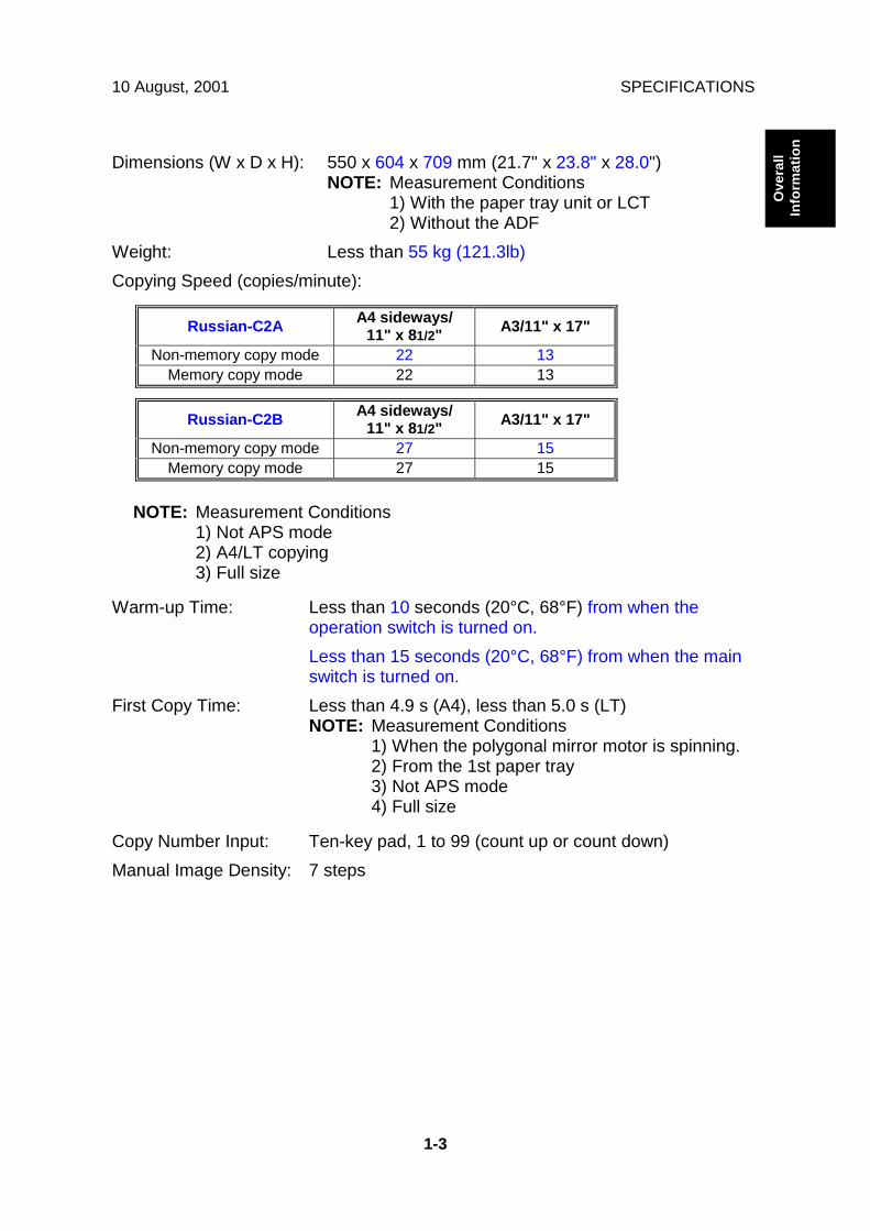
Dimensions (W x D x H): 550 x 604 x 709 mm (21.7" x 23.8" x 28.0")NOTE: Measurement Conditions
1) With the paper tray unit or LCT2) Without the ADF
Weight: Less than 55 kg (121.3lb)Copying Speed (copies/minute):
Russian-C2A A4 sideways/11" x 81/2" A3/11" x 17"
Non-memory copy mode 22 13Memory copy mode 22 13
Russian-C2B A4 sideways/11" x 81/2" A3/11" x 17"
Non-memory copy mode 27 15Memory copy mode 27 15
NOTE: Measurement Conditions1) Not APS mode2) A4/LT copying3) Full size
Warm-up Time: Less than 10 seconds (20°C, 68°F) from when theoperation switch is turned on.Less than 15 seconds (20°C, 68°F) from when the mainswitch is turned on.
First Copy Time: Less than 4.9 s (A4), less than 5.0 s (LT)NOTE: Measurement Conditions
1) When the polygonal mirror motor is spinning.2) From the 1st paper tray3) Not APS mode4) Full size
Copy Number Input: Ten-key pad, 1 to 99 (count up or count down)Manual Image Density: 7 steps
SPECIFICATIONS 10 August, 2001
1-4
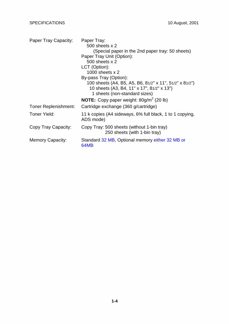
Paper Tray Capacity: Paper Tray:500 sheets x 2
(Special paper in the 2nd paper tray: 50 sheets)Paper Tray Unit (Option):
500 sheets x 2LCT (Option):
1000 sheets x 2By-pass Tray (Option):
100 sheets (A4, B5, A5, B6, 81/2" x 11", 51/2" x 81/2") 10 sheets (A3, B4, 11" x 17", 81/2" x 13") 1 sheets (non-standard sizes)
NOTE: Copy paper weight: 80g/m2 (20 lb)Toner Replenishment: Cartridge exchange (360 g/cartridge)Toner Yield: 11 k copies (A4 sideways, 6% full black, 1 to 1 copying,
ADS mode)Copy Tray Capacity: Copy Tray: 500 sheets (without 1-bin tray)
250 sheets (with 1-bin tray)Memory Capacity: Standard 32 MB, Optional memory either 32 MB or
64MB

10 August, 2001 MACHINE CONFIGURATION
1-5
Ove
rall
Info
rmat
ion1.2 MACHINE CONFIGURATION
1.2.1 SYSTEM COMPONENTS
B027V501.WMF
9
1 2
3
4
5
6
78
12
10
11
13

MACHINE CONFIGURATION 10 August, 2001
1-6
Version Item MachineCode No. Comments
Copier(R-C2a) B022 13Copier(R-C2b) B027 13ARDF (Optional) B386 2 1), and new features addedPlaten Cover (Optional) B406 1 Common with K-C1Paper Tray Unit-2 tray (Optional) B390 8 1) and 2)LCT (Optional) B391 7 1) and 2)1-bin Tray (Optional) B413 3 1)Shift Tray (Optional) B459 12 1)Duplex Unit (Optional) B414 5 1) and 2)By-pass Tray (Optional) B415 6 1)Interchange Unit (Optional) B416 4 1)Bridge Unit (Optional) B417 11 1) and 2)1000-sheet finisher (Optional) B408 10 New option500-sheet finisher (Optional) B442 9 1)
The components are thesame as the 500-finisher forRussian-P2
User Account Enhance Unit(Optional)
B443 Common with A-C2
HDD (Optional) B420Memory – 32 MB (Optional) G578 Common with A-C2Memory – 64 MB (Optional) G579 Common with A-C2
Copier
Key Counter Bracket (Optional) B452 1)Fax Controller (Optional) B418G3 Interface Unit (Optional) B448ISDN (Optional) B449Fax Function Expander(Optional)
A892 Common with R-C1
Fax
Handset (Optional) B433 Common with Kir-CPrinter Unit (Optional) B461Printer/Scanner Unit (Optional) B453PS3 (Optional) B462NIB (Optional) G335
Printer /Scanner
IEEE1394 (Optional) G590 Common with A-C2
Comments:The following are the differences between Russian-C1 and this machine.1) New color for the exterior cover2) The drive motor and the control board have been changed so they will be
compatible with R-C2c (32 cpm machine)
10 August, 2001 MACHINE CONFIGURATION
1-7
Ove
rall
Info
rmat
ion
1.2.2 INSTALLABLE OPTION TABLE
Copier options
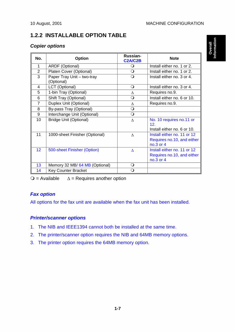
No. Option Russian-C2A/C2B Note
1 ARDF (Optional) ! Install either no. 1 or 2.2 Platen Cover (Optional) ! Install either no. 1 or 2.3 Paper Tray Unit – two-tray
(Optional)! Install either no. 3 or 4.
4 LCT (Optional) ! Install either no. 3 or 4.5 1-bin Tray (Optional) ∆ Requires no.9.6 Shift Tray (Optional) ! Install either no. 6 or 10.7 Duplex Unit (Optional) ∆ Requires no.9.8 By-pass Tray (Optional) !9 Interchange Unit (Optional) !
10 Bridge Unit (Optional) ∆ No. 10 requires no.11 or12.Install either no. 6 or 10.
11 1000-sheet Finisher (Optional) ∆ Install either no. 11 or 12Requires no.10, and eitherno.3 or 4
12 500-sheet Finisher (Option) ∆ Install either no. 11 or 12Requires no.10, and eitherno.3 or 4
13 Memory 32 MB/ 64 MB (Optional) !14 Key Counter Bracket !
! = Available ∆ = Requires another option
Fax optionAll options for the fax unit are available when the fax unit has been installed.
Printer/scanner options
1. The NIB and IEEE1394 cannot both be installed at the same time.2. The printer/scanner option requires the NIB and 64MB memory options.3. The printer option requires the 64MB memory option.

PAPER PATH 10 August, 2001
1-8
1.3 PAPER PATH
1. Optional ADF2. Optional 1-bin Tray3. Optional Interchange Unit4. Optional Duplex Unit5. Optional By-pass Feed Tray6. Optional Paper Tray Unit7. Optional 1000-sheet Finisher8. Optional Bridge Unit
B022V155.WMF
1
2
3
4
5
6
7
8

10 August, 2001 MECHANICAL COMPONENT LAYOUT
1-9
Ove
rall
Info
rmat
ion1.4 MECHANICAL COMPONENT LAYOUT
B027V502.WMF
1 2 3 4 5 6 7
8
9
10
11
12
1314151617
18
19
20
2122
23
24
25
26
27
28

MECHANICAL COMPONENT LAYOUT 10 August, 2001
1-10
1. 2nd scanner2. Original width sensor3. Exposure lamp4. 1st scanner5. Original length sensor6. Lens7. Scanner motor8. SBU board9. Exit roller10. Fusing hot roller11. Fusing pressure roller12. Cleaning unit13. OPC drum14. Transfer roller
15. Development roller16. ID sensor17. Registration roller18. Friction pad19. Paper feed roller20. Paper size sensor21. Bottom plate22. Tray heater23. Polygon mirror motor24. Laser unit25. Toner supply bottle holder26. Drum charge roller27. Anti-condensation heater28. Scanner home position sensor

10 August, 2001 ELECTRICAL COMPONENT DESCRIPTIONS
1-11
Ove
rall
Info
rmat
ion1.5 ELECTRICAL COMPONENT DESCRIPTIONS
Refer to the electrical component layout on the reverse side of the point-to-pointdiagram for the location of the components.
Symbol Name FunctionMotors
M1 Scanner Drives the 1st and 2nd scanners.M2 Polygonal Mirror Turns the polygonal mirror.M3 Main Drives the main unit components.M4 Exhaust Fan Removes heat from around the fusing unit.M5 Upper Paper Lift Raises the bottom plate in the 1st paper tray.M6 Lower Paper Lift Raises the bottom plate in the 2nd paper tray.
M7 Toner Supply Rotates the toner bottle to supply toner to thedevelopment unit.
Magnetic ClutchesMC1 Upper Paper Feed Starts paper feed from the 1st paper tray.MC2 Lower Paper Feed Starts paper feed from the 2nd paper tray.MC3 Upper Relay Drives the upper relay rollers.MC4 Lower Relay Drives the lower relay rollers.MC4 Registration Drives the registration rollers.
Switches
SW1 Main Provides power to the machine. If this is off, there isno power supplied to the machine.
SW2 Right Upper Cover Detects whether the right upper cover is open or not.
SW3 Right Cover Cuts the +5VLD and +24V dc power line and detectswhether the right cover is open or not.
SW4 Right Lower Cover Detects whether the right lower cover is open or not.
SW5 Upper Paper Size Determines what size of paper is in the upper papertray.
SW6 Lower Paper Size Determines what size of paper is in the lower papertray.
SW7 New PCU Detect Detects when a new PCU is installed.
SW8 Front Cover Safety Cuts the +5VLD and +24V dc power line and detectswhether the front cover is open or not.
SW9 Operation Provides power for machine operation. The machinestill has power if this switch is off.
Sensors
S1 Scanner HP Informs the CPU when the 1st and 2nd scanners areat home position.
S2 Platen Cover Informs the CPU that the platen cover is in the up ordown position (related to the APS/ARE functions).
S3 Original Width Detects original width. This is one of the APS (AutoPaper Select) sensors.
S4 Original Length 1 Detects original length. This is one of the APS (AutoPaper Select) sensors.
ELECTRICAL COMPONENT DESCRIPTIONS 10 August, 2001
1-12
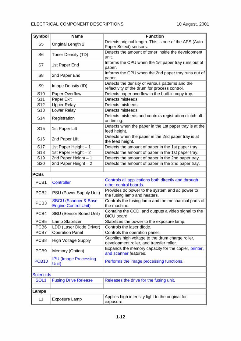
Symbol Name Function
S5 Original Length 2 Detects original length. This is one of the APS (AutoPaper Select) sensors.
S6 Toner Density (TD) Detects the amount of toner inside the developmentunit.
S7 1st Paper End Informs the CPU when the 1st paper tray runs out ofpaper.
S8 2nd Paper End Informs the CPU when the 2nd paper tray runs out ofpaper.
S9 Image Density (ID) Detects the density of various patterns and thereflectivity of the drum for process control.
S10 Paper Overflow Detects paper overflow in the built-in copy tray.S11 Paper Exit Detects misfeeds.S12 Upper Relay Detects misfeeds.S13 Lower Relay Detects misfeeds.
S14 Registration Detects misfeeds and controls registration clutch off-on timing.
S15 1st Paper Lift Detects when the paper in the 1st paper tray is at thefeed height.
S16 2nd Paper Lift Detects when the paper in the 2nd paper tray is atthe feed height.
S17 1st Paper Height – 1 Detects the amount of paper in the 1st paper tray.S18 1st Paper Height – 2 Detects the amount of paper in the 1st paper tray.S19 2nd Paper Height – 1 Detects the amount of paper in the 2nd paper tray.S20 2nd Paper Height – 2 Detects the amount of paper in the 2nd paper tray.
PCBs
PCB1 Controller Controls all applications both directly and throughother control boards.
PCB2 PSU (Power Supply Unit) Provides dc power to the system and ac power tothe fusing lamp and heaters.
PCB3 SBCU (Scanner & BaseEngine Control Unit)
Controls the fusing lamp and the mechanical parts ofthe machine.
PCB4 SBU (Sensor Board Unit) Contains the CCD, and outputs a video signal to theBICU board.
PCB5 Lamp Stabilizer Stabilizes the power to the exposure lamp.PCB6 LDD (Laser Diode Driver) Controls the laser diode.PCB7 Operation Panel Controls the operation panel.
PCB8 High Voltage Supply Supplies high voltage to the drum charge roller,development roller, and transfer roller.
PCB9 Memory (Option) Expands the memory capacity for the copier, printer,and scanner features.
PCB10 IPU (Image ProcessingUnit) Performs the image processing functions.
SolenoidsSOL1 Fusing Drive Release Releases the drive for the fusing unit.
Lamps
L1 Exposure Lamp Applies high intensity light to the original forexposure.

10 August, 2001 ELECTRICAL COMPONENT DESCRIPTIONS
1-13
Ove
rall
Info
rmat
ion
Symbol Name FunctionL2 Main Fusing Lamp Heats the center of the hot roller.L3 Secondary Fusing Lamp Heats both ends of the hot roller.
L4 Quenching Lamp Neutralizes any charge remaining on the drumsurface after cleaning.
Heaters
H1 Anti-condensation(Option)
Turns on when the main power switch is off toprevent moisture from forming on the optics.
H2 Tray (Option)Turns on when the main power switch is off toprevent moisture from forming around the papertrays.
Others
TS1 Fusing Thermostats Opens the fusing lamp circuit if the fusing unitoverheats.
TH1 Fusing Thermistors Detects the temperature of the hot roller.
LSD 1 Laser SynchronizationDetector
Detects the laser beam at the start of the main scan.
CO1 Mechanical Counter Keeps track of the total number of prints made.
CO2 Key Counter (Option)Used for control of authorized use. If this feature isenabled for copying, copying will be impossible untilit is installed.

DRIVE LAYOUT 10 August, 2001
1-14
1.6 DRIVE LAYOUT
1. Scanner Drive Motor2. Main Motor3. Registration Clutch4. Upper Paper Feed Clutch5. Upper Transport Clutch6. Lower Paper Feed Clutch7. Lower Transport Clutch
B027V301.WMF
B027V302.WMF
1
2
3
4
5
6
7
Scanner
Fusing
PCU/Transfer Drive

10 August, 2001 COPY PROCESS
1-15
Ove
rall
Info
rmat
ion1.7 COPY PROCESS
1.7.1 OVERVIEW
1. EXPOSUREA xenon lamp exposes the original. Light reflected from the original passes tothe CCD, where it is converted into an analog data signal. This data isconverted to a digital signal, processed and stored in the memory. At the timeof printing, the data is retrieved and sent to the laser diode. For multi-copy runs,the original is scanned once only and stored to the memory.
2. DRUM CHARGEIn the dark, the charge roller gives a negative charge to the organic photo-conductive (OPC) drum. The charge remains on the surface of the drumbecause the OPC layer has a high electrical resistance in the dark.
B027V101.WMF
B027V401.WMF
1
2
3
4
6
5
7
89

COPY PROCESS 10 August, 2001
1-16
3. LASER EXPOSUREThe processed data scanned from the original is retrieved from the memoryand transferred to the drum by a laser beam, which forms an electrical latentimage on the drum surface. The amount of charge remaining as a latent imageon the drum depends on the laser beam intensity, which is controlled by theBICU board.
4. DEVELOPMENTThe magnetic developer brush on the development rollers comes in contactwith the latent image on the drum surface. Toner particles are electrostaticallyattached to the areas of the drum surface where the laser reduced the negativecharge on the drum.
5. ID SENSORThe laser forms a sensor pattern on the drum surface. The ID sensor measuresthe reflectivity of the pattern. The output signal is one of the factors used fortoner supply control. Also, the ID sensor measures the reflectivity of the drumsurface. The output signal is used for charge roller voltage control.
6. IMAGE TRANSFERPaper is fed to the area between the drum surface and the transfer roller at theproper time for aligning the copy paper and the developed image on the drumsurface. Then, the transfer roller applies a high positive charge to the reverseside of the paper. This positive charge pulls the toner particles from the drumsurface onto the paper. At the same time, the paper is electrostatically attractedto the transfer roller.
7. PAPER SEPARATIONPaper separates from the drum as a result of the electrostatic attractionbetween the paper and the transfer roller. The discharge plate helps separatethe paper from the drum.
8. CLEANINGThe cleaning blade removes any toner remaining on the drum surface after theimage transfers to the paper.
9. QUENCHINGThe light from the quenching lamp electrically neutralizes the charge on thedrum surface.

10 August, 2001 BOARD STRUCTURE
1-17
Ove
rall
Info
rmat
ion1.8 BOARD STRUCTURE
1.8.1 OVERVIEW
SBCU
By-pass Duplex 1-Bin Tray BridgeUnit Finisher Sensors Clutches/
Solenoids
HighVoltage
P.P
Ther-mistors
PSU
Motors
PaperTray Unit/
LCTARDF APS
SensorsLamp
StabilizerScanner
Motor
IPU
LSD
LD Unit
NIB
SBU
OperationPanel
PolygonMotor
Xenon Lamp
FaxOptions
Fusi
ng L
amps
: Standard
: OptionController
Fax Unit
IEEE1394
HDD
B027V500.WMF
BOARD STRUCTURE 10 August, 2001
1-18
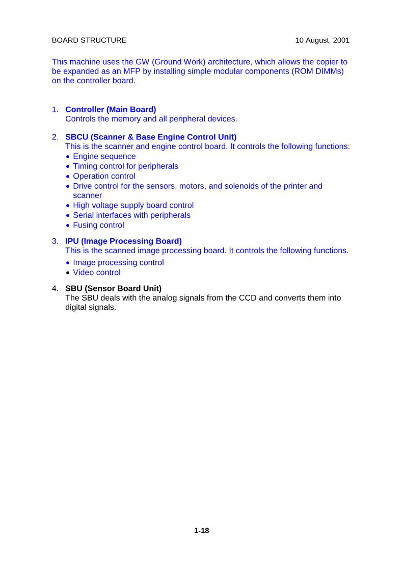
This machine uses the GW (Ground Work) architecture, which allows the copier tobe expanded as an MFP by installing simple modular components (ROM DIMMs)on the controller board.
1. Controller (Main Board)Controls the memory and all peripheral devices.
2. SBCU (Scanner & Base Engine Control Unit)This is the scanner and engine control board. It controls the following functions:• Engine sequence• Timing control for peripherals• Operation control• Drive control for the sensors, motors, and solenoids of the printer and
scanner• High voltage supply board control• Serial interfaces with peripherals• Fusing control
3. IPU (Image Processing Board)This is the scanned image processing board. It controls the following functions.• Image processing control• Video control
4. SBU (Sensor Board Unit)The SBU deals with the analog signals from the CCD and converts them intodigital signals.
10 August, 2001 BOARD STRUCTURE
1-19
Ove
rall
Info
rmat
ion
1.8.2 CONTROLLER
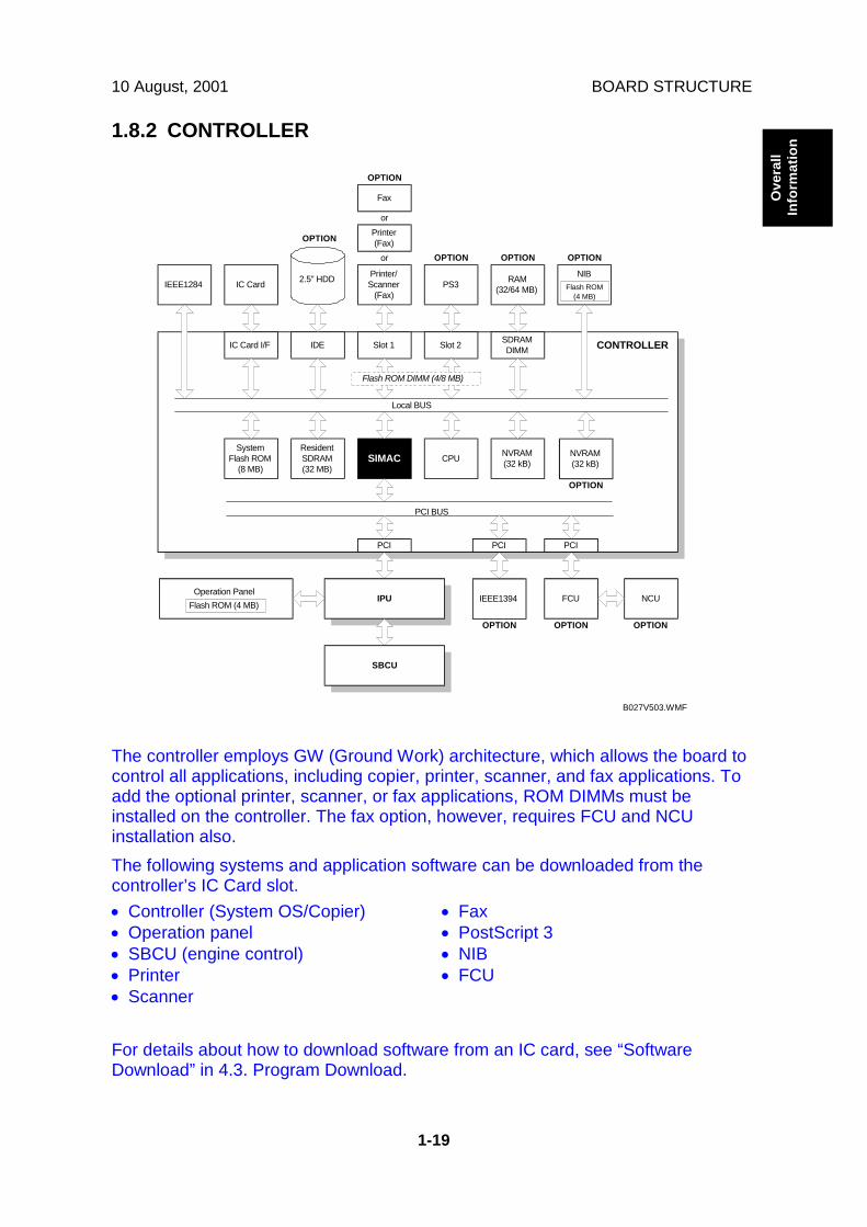
The controller employs GW (Ground Work) architecture, which allows the board tocontrol all applications, including copier, printer, scanner, and fax applications. Toadd the optional printer, scanner, or fax applications, ROM DIMMs must beinstalled on the controller. The fax option, however, requires FCU and NCUinstallation also.The following systems and application software can be downloaded from thecontroller’s IC Card slot.• Controller (System OS/Copier)• Operation panel• SBCU (engine control)• Printer• Scanner
• Fax• PostScript 3• NIB• FCU
For details about how to download software from an IC card, see “SoftwareDownload” in 4.3. Program Download.
IEEE1284 IC CardPrinter/Scanner
(Fax)PS3 RAM
(32/64 MB)
NIB
Printer(Fax)
Fax
IC Card I/F IDE Slot 1 Slot 2 SDRAMDIMM
SystemFlash ROM
(8 MB)
ResidentSDRAM(32 MB)
SIMAC CPU NVRAM(32 kB)
PCI
or
or OPTION OPTION OPTION
OPTION
Flash ROM(4 MB)
2.5" HDD
Flash ROM DIMM (4/8 MB)
CONTROLLER
NVRAM(32 kB)
OPTION
PCIPCI
IPU FCU NCU
SBCU
Operation PanelFlash ROM (4 MB)
OPTION
IEEE1394
OPTION
PCI BUS
Local BUS
OPTION
OPTION
B027V503.WMF
BOARD STRUCTURE 10 August, 2001
1-20
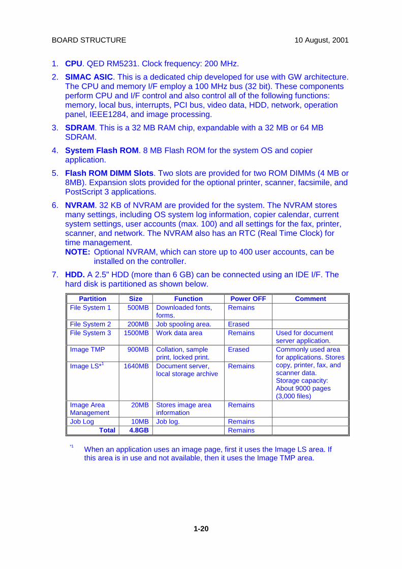
1. CPU. QED RM5231. Clock frequency: 200 MHz.2. SIMAC ASIC. This is a dedicated chip developed for use with GW architecture.
The CPU and memory I/F employ a 100 MHz bus (32 bit). These componentsperform CPU and I/F control and also control all of the following functions:memory, local bus, interrupts, PCI bus, video data, HDD, network, operationpanel, IEEE1284, and image processing.
3. SDRAM. This is a 32 MB RAM chip, expandable with a 32 MB or 64 MBSDRAM.
4. System Flash ROM. 8 MB Flash ROM for the system OS and copierapplication.
5. Flash ROM DIMM Slots. Two slots are provided for two ROM DIMMs (4 MB or8MB). Expansion slots provided for the optional printer, scanner, facsimile, andPostScript 3 applications.
6. NVRAM. 32 KB of NVRAM are provided for the system. The NVRAM storesmany settings, including OS system log information, copier calendar, currentsystem settings, user accounts (max. 100) and all settings for the fax, printer,scanner, and network. The NVRAM also has an RTC (Real Time Clock) fortime management.NOTE: Optional NVRAM, which can store up to 400 user accounts, can be
installed on the controller.7. HDD. A 2.5" HDD (more than 6 GB) can be connected using an IDE I/F. The
hard disk is partitioned as shown below.
Partition Size Function Power OFF CommentFile System 1 500MB Downloaded fonts,
forms.Remains
File System 2 200MB Job spooling area. ErasedFile System 3 1500MB Work data area Remains Used for document
server application.Image TMP 900MB Collation, sample
print, locked print.Erased
Image LS*1 1640MB Document server,local storage archive
Remains
Commonly used areafor applications. Storescopy, printer, fax, andscanner data.Storage capacity:About 9000 pages(3,000 files)
Image AreaManagement
20MB Stores image areainformation
Remains
Job Log 10MB Job log. RemainsTotal 4.8GB Remains
*1 When an application uses an image page, first it uses the Image LS area. Ifthis area is in use and not available, then it uses the Image TMP area.

10 August, 2001 SCANNING
2-1
Det
aile
dD
escr
iptio
ns
2. DETAILED SECTION DESCRIPTIONS2.1 SCANNING2.1.1 OVERVIEW
The original is illuminated by the exposure lamp (a xenon lamp in this model) [A].The image is reflected onto a CCD (charge coupled device) [B] via the 1st, 2nd, 3rdmirrors, and lens [C].The 1st scanner [D] consists of the exposure lamp, a reflector [E], and the 1stmirror [F].A lamp stabilizer energizes the exposure lamp. The light reflected by the reflector isof almost equal intensity, to reduce shadows on pasted originals.An optics anti-condensation heater [G] is available as an option. It can be installedon the left side of the scanner. It turns on whenever the power cord is plugged in.
B027D556.WMF
[A] [B][C]
[D]
[E]
[F][G]

SCANNING 10 August, 2001
2-2
2.1.2 SCANNER DRIVE
A stepper motor drives the scanner. The 1st and 2nd scanners [A,B] are driven bythe scanner drive motor [C] through the timing belt [D], scanner drive pulley [E],scanner drive shaft [F], and two scanner wires [G].- Book mode -The scanner drive board controls and operates the scanner drive motor. In full sizemode, the 1st scanner speed is 150 mm/s during scanning. The 2nd scannerspeed is half that of the 1st scanner.In reduction or enlargement mode, the scanning speed depends on themagnification ratio. The returning speed is always the same, whether in full size ormagnification mode. The image length change in the sub scan direction is done bychanging the scanner drive motor speed, and in the main scan direction it is doneby image processing on the IPU board.Magnification in the sub-scan direction can be adjusted by changing the scannerdrive motor speed using SP4009. Magnification in the main scan direction can beadjusted using SP4008.- ADF mode -The scanners are always kept at their home position (the scanner H.P sensor [H]detects the 1st scanner) to scan the original. The ADF motor feeds the originalthrough the ADF. In reduction/enlargement mode, the image length change in thesub-scan direction is done by changing the ADF motor speed. Magnification in themain scan direction is done in the IPU board, like for book mode.Magnification in the sub-scan direction can be adjusted by changing the ADF motorspeed using SP6006. In the main scan direction, it can be adjusted with SP4008,like for book mode.
B022D002.WMF
[A][B] [C][D]
[E][F]
[G] [E]
[G][H]

10 August, 2001 SCANNING
2-3
Det
aile
dD
escr
iptio
ns
2.1.3 ORIGINAL SIZE DETECTION IN PLATEN MODE
In the optics cavity for original size detection, there are four reflective sensors inthe 115V machines ([A] and [B]), and six reflective sensors in the 230V machines.The original width sensors [A] detect the original width, and the original lengthsensors [B] and [C] detect the original length. These are the APS (Auto PaperSelect) sensors. Each APS sensor is a reflective photosensor.While the main switch is on, these sensors are active and the original size data isalways sent to the CPU. However, the CPU checks the data only when the platencover sensor [D] is activated. This is when the platen is positioned about 15 cmabove the exposure glass, for example while it is being closed. The CPU canrecognize the original size from the combination of on/off signals from the APSsensors.If the copy is made with the platen fully open, the CPU decides the original sizefrom the sensor outputs when the Start key is pressed.
B027D554.WMF
[A]
[B]
[C]
[D]

SCANNING 10 August, 2001
2-4
Original Size Length Sensor Width SensorA4/A3
versionLT/DLTversion L4 L3 L2 L1 W2 W1
A3 11" x 17" O O O O O OB4 10" x 14" O O O O O XFoolscap 8.5" x 13" O O O X X XA4-L 8.5" x 11" O O X X X XB5-L O X X X X XA4-S 11" x 8.5" X X X X O OB5-S X X X X O XA5-L, A5-S X X X X X X
NOTE: 1) L: Lengthwise, S: Sideways, O: High (paper present), X: Low2) The length sensors L3 and L4 are used only for 230V machines.
For other combinations, "CANNOT DETECT ORIG. SIZE" will be indicated on theoperation panel display (if SP 4-303 is kept at the default setting).The above table shows the outputs of the sensors for each original size. Thisoriginal size detection method eliminates the necessity for a pre-scan andincreases the machine's productivity.However, if the by-pass feeder is used, note that the machine assumes that thecopy paper is lengthwise. For example, if A4 sideways paper is placed on the by-pass tray, the machine assumes it is A3 paper and scans the full A3 area for thefirst copy of each page of the original, disregarding the original size sensors.However, for each page, the data signal to the laser diode is stopped to match thecopy paper length detected by the registration sensor.Original size detection using the ADF is described in the manual for the ADF.
W2
W1
L1L2
L3L4
B027D555.WMF
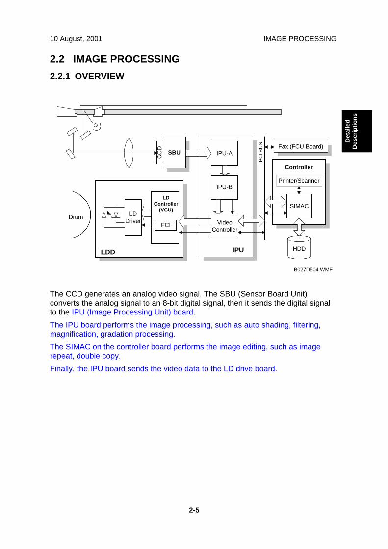
10 August, 2001 IMAGE PROCESSING
2-5
Det
aile
dD
escr
iptio
ns
2.2 IMAGE PROCESSING2.2.1 OVERVIEW
The CCD generates an analog video signal. The SBU (Sensor Board Unit)converts the analog signal to an 8-bit digital signal, then it sends the digital signalto the IPU (Image Processing Unit) board.The IPU board performs the image processing, such as auto shading, filtering,magnification, gradation processing.The SIMAC on the controller board performs the image editing, such as imagerepeat, double copy.Finally, the IPU board sends the video data to the LD drive board.
Drum
IPULDD
SBUC
CD
FCI
LDController
(VCU)LD
Driver
Fax (FCU Board)
IPU-B
VideoController
Printer/Scanner
SIMAC
HDD
Controller
PCI B
US
IPU-A
B027D504.WMF
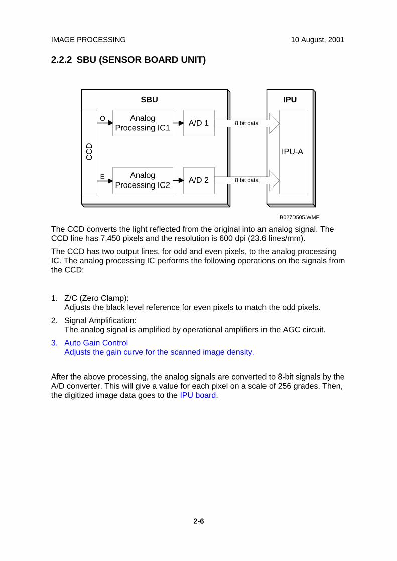
IMAGE PROCESSING 10 August, 2001
2-6
2.2.2 SBU (SENSOR BOARD UNIT)
The CCD converts the light reflected from the original into an analog signal. TheCCD line has 7,450 pixels and the resolution is 600 dpi (23.6 lines/mm).The CCD has two output lines, for odd and even pixels, to the analog processingIC. The analog processing IC performs the following operations on the signals fromthe CCD:
1. Z/C (Zero Clamp):Adjusts the black level reference for even pixels to match the odd pixels.
2. Signal Amplification:The analog signal is amplified by operational amplifiers in the AGC circuit.
3. Auto Gain ControlAdjusts the gain curve for the scanned image density.
After the above processing, the analog signals are converted to 8-bit signals by theA/D converter. This will give a value for each pixel on a scale of 256 grades. Then,the digitized image data goes to the IPU board.
SBU
IPU-A
IPU
AnalogProcessing IC1 A/D 1 8 bit data
AnalogProcessing IC2 A/D 2 8 bit dataE
CC
D
O
B027D505.WMF

10 August, 2001 IMAGE PROCESSING
2-7
Det
aile
dD
escr
iptio
ns
2.2.3 AUTO IMAGE DENSITY
ADS prevents the background of an original from appearing on copies.The copier scans the auto image density detection area [A] as shown in thediagram. This corresponds to a few mm at one end of the main scan line. As thescanner scans down the page, the SBU detects the peak white level for each scanline. The IPU performs the ADS function in accordance with the peak white level.When an original with a gray background is scanned, the density of the gray areais the peak white level density. Therefore, the original background will not appearon copies. Because peak level data is taken for each scan line, ADS corrects forany changes in background density down the page.As with previous digital copiers, the user can select manual image density whenselecting auto image density mode, and the machine will use both settings whenprocessing the original.
80mm20mm
0.5mm
Sub scan direction
B027D552.WMF
[A]

IMAGE PROCESSING 10 August, 2001
2-8
2.2.4 IPU (IMAGE PROCESSING UNIT)
Overview
The image data from the SBU goes to the IPU (Image Processing Unit) ICs on theSBCU board, which carry out the following processes on the image data.IPU-A
• Auto shading• Pre-filtering• Magnification• Test pattern generation
IPU-B• Filtering (MTF and smoothing)• ID gamma correction• Grayscale processing• Binary picture processing• Error diffusion• Dithering
Video Controller• Video path control
The image data then goes to the LD driver (LDD).
IPU
LDD
SBU
FCI
VCU
Fax (FCU Board)
IPU-B
VideoController
Printer/Scanner
SIMAC
HDD
Controller
PCI B
US
IPU-A
B027D507.WMF
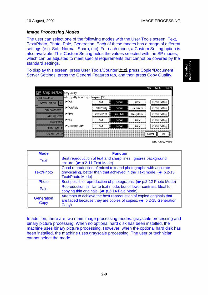
10 August, 2001 IMAGE PROCESSING
2-9
Det
aile
dD
escr
iptio
ns
Image Processing ModesThe user can select one of the following modes with the User Tools screen: Text,Text/Photo, Photo, Pale, Generation. Each of these modes has a range of differentsettings (e.g. Soft, Normal, Sharp, etc). For each mode, a Custom Setting option isalso available. This Custom Setting holds the values selected with the SP modes,which can be adjusted to meet special requirements that cannot be covered by thestandard settings.To display this screen, press User Tools/Counter , press Copier/DocumentServer Settings, press the General Features tab, and then press Copy Quality.
Mode Function
Text Best reproduction of text and sharp lines. Ignores backgroundtexture. (☛ p.2-11 Text Mode)
Text/PhotoGood reproduction of mixed text and photographs with accurategrayscaling, better than that achieved in the Text mode. (☛ p.2-13Text/Photo Mode)
Photo Best possible reproduction of photographs. (☛ p.2-12 Photo Mode)
Pale Reproduction similar to text mode, but of lower contrast. Ideal forcopying thin originals. (☛ p.2-14 Pale Mode)
GenerationCopy
Attempts to achieve the best reproduction of copied originals thatare faded because they are copies of copies. (☛ p.2-15 GenerationCopy)
In addition, there are two main image processing modes: grayscale processing andbinary picture processing. When no optional hard disk has been installed, themachine uses binary picture processing. However, when the optional hard disk hasbeen installed, the machine uses grayscale processing. The user or techniciancannot select the mode.
B027D800.WMF
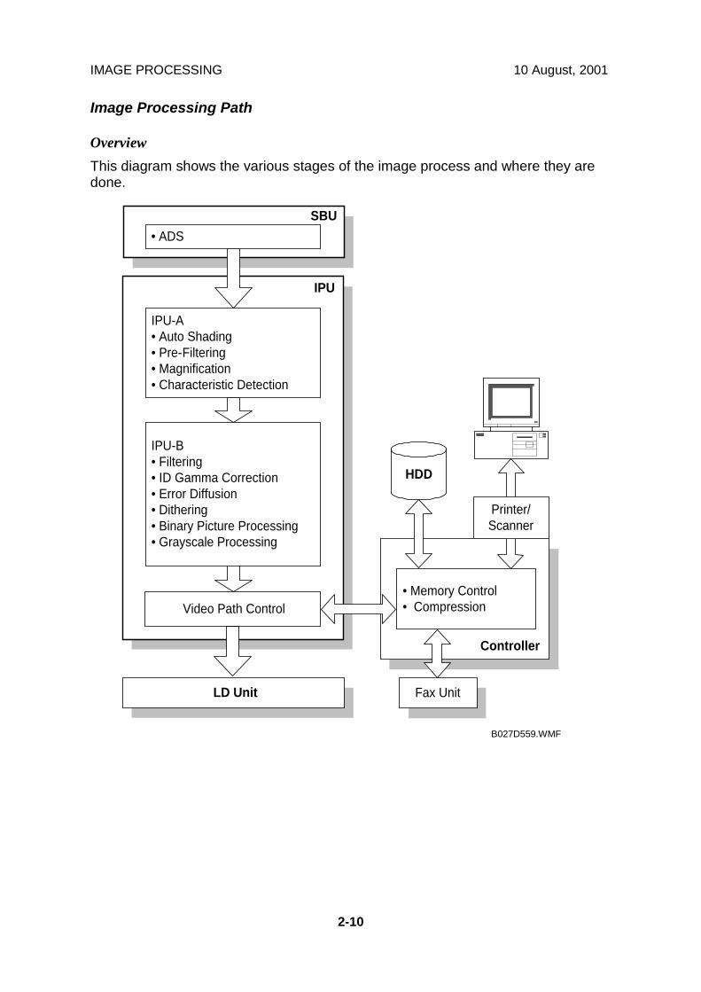
IMAGE PROCESSING 10 August, 2001
2-10
Image Processing Path
OverviewThis diagram shows the various stages of the image process and where they aredone.
• Memory Control• Compression
SBU• ADS
Fax Unit
IPU-A• Auto Shading• Pre-Filtering• Magnification• Characteristic Detection
IPU-B• Filtering• ID Gamma Correction• Error Diffusion• Dithering• Binary Picture Processing• Grayscale Processing
Video Path Control
LD Unit
Controller
HDD
IPU
Printer/Scanner
B027D559.WMF
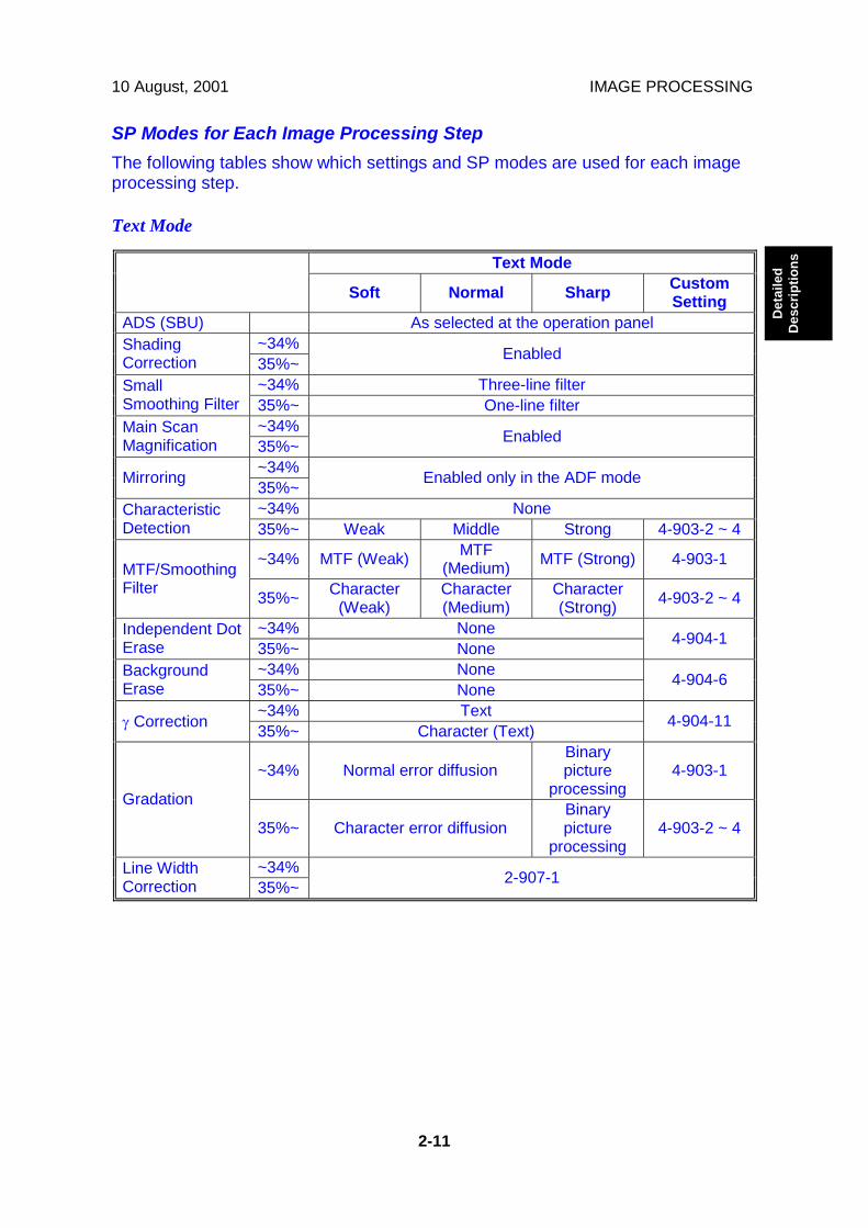
10 August, 2001 IMAGE PROCESSING
2-11
Det
aile
dD
escr
iptio
ns
SP Modes for Each Image Processing StepThe following tables show which settings and SP modes are used for each imageprocessing step.
Text Mode
Text Mode
Soft Normal Sharp CustomSetting
ADS (SBU) As selected at the operation panel~34%Shading
Correction 35%~ Enabled
~34% Three-line filterSmallSmoothing Filter 35%~ One-line filter
~34%Main ScanMagnification 35%~ Enabled
~34%Mirroring 35%~ Enabled only in the ADF mode
~34% NoneCharacteristicDetection 35%~ Weak Middle Strong 4-903-2 ~ 4
~34% MTF (Weak) MTF(Medium) MTF (Strong) 4-903-1MTF/Smoothing
Filter 35%~ Character(Weak)
Character(Medium)
Character(Strong) 4-903-2 ~ 4
~34% NoneIndependent DotErase 35%~ None 4-904-1
~34% NoneBackgroundErase 35%~ None 4-904-6
~34% Textγ Correction 35%~ Character (Text) 4-904-11
~34% Normal error diffusionBinarypicture
processing4-903-1
Gradation
35%~ Character error diffusionBinarypicture
processing4-903-2 ~ 4
~34%Line WidthCorrection 35%~ 2-907-1
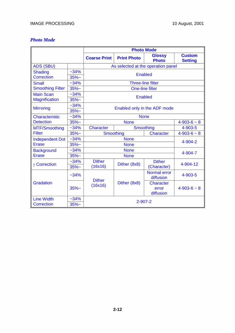
IMAGE PROCESSING 10 August, 2001
2-12
Photo Mode
Photo Mode
Coarse Print Print Photo GlossyPhoto
CustomSetting
ADS (SBU) As selected at the operation panel~34%Shading
Correction 35%~ Enabled
~34% Three-line filterSmallSmoothing Filter 35%~ One-line filter
~34%Main ScanMagnification 35%~ Enabled
~34%Mirroring 35%~ Enabled only in the ADF mode
~34% NoneCharacteristicDetection 35%~ None 4-903-6 ~ 8
~34% Character Smoothing 4-903-5MTF/SmoothingFilter 35%~ Smoothing Character 4-903-6 ~ 8
~34% NoneIndependent DotErase 35%~ None 4-904-2
~34% NoneBackgroundErase 35%~ None 4-904-7
~34%γ Correction 35%~
Dither(16x16) Dither (8x8) Dither
(Character) 4-904-12
~34% Normal errordiffusion 4-903-5
Gradation35%~
Dither(16x16) Dither (8x8) Character
errordiffusion
4-903-6 ~ 8
~34%Line WidthCorrection 35%~ 2-907-2
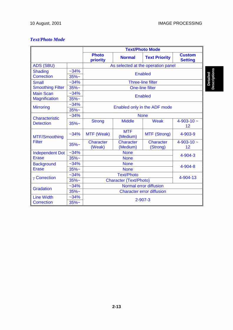
10 August, 2001 IMAGE PROCESSING
2-13
Det
aile
dD
escr
iptio
ns
Text/Photo Mode
Text/Photo ModePhoto
priority Normal Text Priority CustomSetting
ADS (SBU) As selected at the operation panel~34%Shading
Correction 35%~ Enabled
~34% Three-line filterSmallSmoothing Filter 35%~ One-line filter
~34%Main ScanMagnification 35%~ Enabled
~34%Mirroring 35%~ Enabled only in the ADF mode
~34% NoneCharacteristicDetection 35%~ Strong Middle Weak 4-903-10 ~
12
~34% MTF (Weak) MTF(Medium) MTF (Strong) 4-903-9MTF/Smoothing
Filter 35%~ Character(Weak)
Character(Medium)
Character(Strong)
4-903-10 ~12
~34% NoneIndependent DotErase 35%~ None 4-904-3
~34% NoneBackgroundErase 35%~ None 4-904-8
~34% Text/Photoγ Correction 35%~ Character (Text/Photo) 4-904-13
~34% Normal error diffusionGradation 35%~ Character error diffusion~34%Line Width
Correction 35%~ 2-907-3

IMAGE PROCESSING 10 August, 2001
2-14
Pale Mode
Pale ModePhoto
priority Normal Text Priority CustomSetting
ADS (SBU) As selected at the operation panel~34%Shading
Correction 35%~ Enabled
~34% Three-line filterSmallSmoothing Filter 35%~ One-line filter
~34%Main ScanMagnification 35%~ Enabled
~34%Mirroring 35%~ Enabled only in the ADF mode
~34% NoneCharacteristicDetection 35%~ Weak Middle Strong 4-903-14 ~
16
~34% MTF (Weak) MTF(Medium) MTF (Strong) 4-903-13MTF/Smoothing
Filter 35%~ Character(Weak)
Character(Medium)
Character(Strong)
4-903-14 ~16
~34% NoneIndependent DotErase 35%~ None 4-904-4
~34% NoneBackgroundErase 35%~ None 4-904-9
~34% Paleγ Correction 35%~ Character (Pale) 4-904-14
~34% Normal error diffusionGradation 35%~ Character error diffusion~34%Line Width
Correction 35%~ 2-907-4

10 August, 2001 IMAGE PROCESSING
2-15
Det
aile
dD
escr
iptio
ns
Generation Copy
Generation Copy ModePhoto
priority Normal Text Priority CustomSetting
ADS (SBU) As selected at the operation panel~34%Shading
Correction 35%~ Enabled
~34% Three-line filterSmallSmoothing Filter 35%~ One-line filter
~34%Main ScanMagnification 35%~ Enabled
~34%Mirroring 35%~ Enabled only in the ADF mode
~34% NoneCharacteristicDetection 35%~ Weak Middle Strong 4-903-18 ~
20
~34% MTF (Weak) MTF(Medium) MTF (Strong) 4-903-17MTF/Smoothing
Filter 35%~ Character(Weak)
Character(Medium)
Character(Strong)
4-903-18 ~20
~34% WeakIndependent DotErase 35%~ Weak 4-904-5
~34% WeakBackgroundErase 35%~ Weak 4-904-10
~34% Generation copyγ Correction 35%~ Character (Generation copy) 4-904-15
~34% Normal error diffusionGradation 35%~ Character error diffusion~34%Line Width
Correction 35%~ 2-907-5
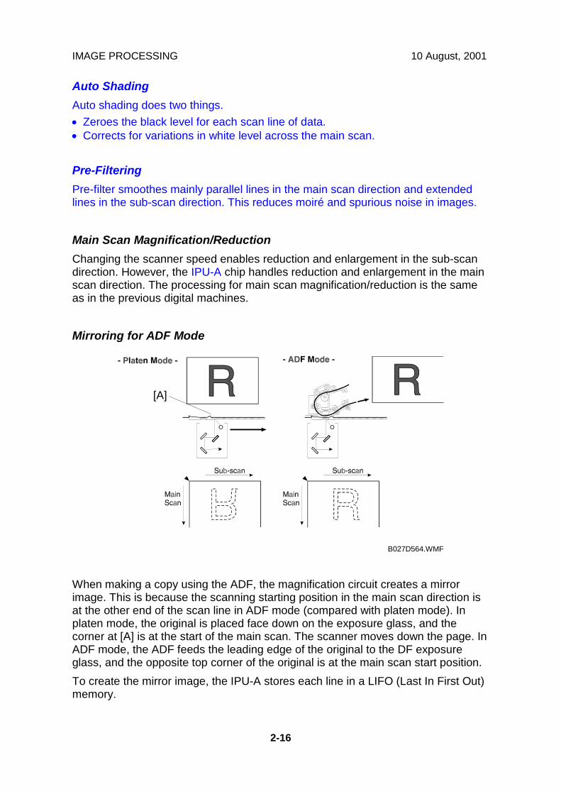
IMAGE PROCESSING 10 August, 2001
2-16
Auto ShadingAuto shading does two things.• Zeroes the black level for each scan line of data.• Corrects for variations in white level across the main scan.
Pre-FilteringPre-filter smoothes mainly parallel lines in the main scan direction and extendedlines in the sub-scan direction. This reduces moiré and spurious noise in images.
Main Scan Magnification/ReductionChanging the scanner speed enables reduction and enlargement in the sub-scandirection. However, the IPU-A chip handles reduction and enlargement in the mainscan direction. The processing for main scan magnification/reduction is the sameas in the previous digital machines.
Mirroring for ADF Mode
When making a copy using the ADF, the magnification circuit creates a mirrorimage. This is because the scanning starting position in the main scan direction isat the other end of the scan line in ADF mode (compared with platen mode). Inplaten mode, the original is placed face down on the exposure glass, and thecorner at [A] is at the start of the main scan. The scanner moves down the page. InADF mode, the ADF feeds the leading edge of the original to the DF exposureglass, and the opposite top corner of the original is at the main scan start position.To create the mirror image, the IPU-A stores each line in a LIFO (Last In First Out)memory.
B027D564.WMF
[A]

10 August, 2001 IMAGE PROCESSING
2-17
Det
aile
dD
escr
iptio
ns
Characteristic DetectionThis function uses software filters to detect edge areas, non-edge areas, and areasof shaded dot patterns.The result determines the image processing that will be applied to each pixel.
FilteringOverviewThere are some software filters for enhancing the desired image qualities of theselected original mode. These filters are the MTF filter, the smoothing filter,characteristic filter, and independent dot erase.Depending on the original mode and the reproduction ratio, the machine will useeither MTF/smoothing, or the filter determined by characteristic detection.If MTF/smoothing is used, it is applied to all areas of the original, regardless ofwhether they are edge areas, non-edge areas, or independent dots.
• The MTF filter emphasizes sharpness and is used in all original types exceptPhoto mode.
• The smoothing filter is used in Photo mode.
If the characteristic filter is used, the filter for each pixel depends on the image datatype that was detected by characteristic detection.
MTF FilterAn MTF filter is used for all original types except Photo mode.When the reproduction ratio is less than 35%, this filter is applied to all image datapixels, regardless of whether they are in an edge area or non-edge area.When the reproduction ratio is 35% or more, the type of MTF filter used for eachpixel depends on the results of characteristic detection.
Smoothing FilterA smoothing filter is used in Photo mode instead of MTF. It is applied to all imagedata pixels, regardless of whether they are in an edge area or non-edge area.With some combinations of reproduction ratio and image mode, the type ofsmoothing used for each pixel depends on the results of characteristic detection(see the Photo mode table in SP Modes for Each Processing Step).
Characteristic FilterA characteristic filter is applied instead of MTF, smoothing, and ID gammacorrection with some combinations of original type and reproduction ratio. See the‘SP Modes for Each Processing Step’ section.For example, In text mode, for the ‘Normal’ original type, if the reproduction ratio isless than 35%, MTF (medium) is used for all pixels in the image. However, if thereproduction ratio is 35% or more, the ‘medium’ characteristic filter is used, and theprocessing depends on whether the pixel was in an edge area, a non-edge area, orin an area shaded using a dot pattern.
IMAGE PROCESSING 10 August, 2001
2-18
Each characteristic filter consists of a combination of the following features: MTF,smoothing, error diffusion, dithering, ID gamma correction. For each of thesefeatures, the machine chooses from two types when making up a characteristicfilter.
Independent Dot EraseIndependent dot erase removes unwanted dots from the image.Independent dot erase is enabled only for Generation Copy mode (according to thedefault settings). However, for the “Custom Setting” original modes, independentdot detection can be enabled and adjusted with SP4-904-2~4. With a larger SPsetting, more dots are detected as independent dots and erased, even if the dotdensity is high. However, dots in mesh-like images may be mistakenly detected asindependent dots.
Background EraseBy default, this process is disabled in all original modes. However, it can beenabled with SP mode.Usually, dirty background is erased using the Auto Image Density (ADS) function.However, sometimes, dirty background areas will still appear. These can be erasedwith this function.The threshold level for erasing can be changed with SP4-904-6~10.
ID Gamma (γγγγ) CorrectionThe machine automatically selects the most appropriate ID gamma correctionbased on the selected original type.Also, for certain combinations of reproduction ratio and original type, characteristicdetection is used. In this case, the machine can use one of two gamma correctiontables. The one that is used is decided separately for each pixel, and depends onthe results of characteristic detection.
Gradation ProcessingOverviewThere are four types of gradation processing:• Grayscale processing: This has 4 output levels for each pixel.• Binary picture processing: This has only two output levels (black and white).• Error diffusion: There are two error diffusion processing types (normal and
characteristic detection)• Dithering: There are two dithering processing types (normal and characteristic
detection).

10 August, 2001 IMAGE PROCESSING
2-19
Det
aile
dD
escr
iptio
ns
Grayscale ProcessingIn this machine, the 8-bit image data is converted into 2-bit data. This produces upto 4 image density levels for each pixel.To realize this, this machine uses a form of pulse width modulation. In thismachine, pulse width modulation consists of the following processes:• Laser diode pulse positioning• Laser diode power/pulse width modulation
Laser diode power and pulse width modulation is done by the laser diode driveboard (LDD). Briefly, the width of the laser pulse for a pixel depends on the outputlevel (image density level: from 0 to 255) required for the pixel.Note that although the LDD can create 256 levels per pixel, the machine only uses8 of these, and only four are used for any one job. A gamma table determineswhich four output levels are used. The gamma table is different for each originaltype setting.
Binary Picture ProcessingThe 8-bit image data is converted into 1-bit data (black and white image data).
Error DiffusionThe error diffusion process reduces the difference in contrast between light anddark areas of a halftone image. Each pixel is corrected using the differencebetween it and the surrounding pixels. The corrected pixels are compared with anerror diffusion matrix.There are two types of error diffusion processing: One is ‘normal’. The other is partof the characteristic detection process, in which the error diffusion method isdetermined separately for each pixel. The error diffusion type (normal orcharacteristic) depends on the reproduction ratio and the original type (refer to theSP Modes for Each Image Processing Step tables).
DitheringEach pixel is compared with the pixel in the same position in a dither matrix.Several matrixes are available, to increase or decrease the detail on the copy.
Line width correctionThis function is effective in all original modes.Usually, lines will bulge in the main scan direction as a result of thenegative/positive development system that is used in this model. So, pixels onedges between black and white areas are compared with adjacent pixels, and if thepixel is on a line, the line thickness will be reduced.Line width correction is done in the VCU chip on the LDD board.The line width correction type can be selected with SP2-907.

IMAGE PROCESSING 10 August, 2001
2-20
2.2.5 VIDEO CONTROL UNIT (VCU)
Fine Character and Image (FCI)The FCI circuit performs image smoothing.
Usually, binary picture processing generates jagged edges on characters, asshown in the above illustration. These are reduced using edge smoothing. The FCIchanges the laser pulse duration and position for certain pixels.Fig. A shows the four possible pulse durations, and Fig. B shows how the laserpulse can be in one of three positions within the pixel. Fig. C shows an example ofhow edge smoothing is used.This function only affects the received image for fax mode and for printer mode,even if copy mode is also using binary picture processing.
4/4 3/4 2/4 1/4 0
Fig. A
Fig. B
Fig. C
Sub ScanDirection
Main Scan Direction
B027D574.WMF

10 August, 2001 LASER EXPOSURE
2-21
Det
aile
dD
escr
iptio
ns
2.3 LASER EXPOSURE2.3.1 OVERVIEW
The optical path from the laser diode to the drum is shown above.The LD unit [A] outputs a laser beam to the polygon mirror [B] through thecylindrical lens [C]. The shield glass [D] prevents dust from reaching the polygonmirror.Each surface of the polygon mirror reflects one full main scan line. The laser beamgoes to the F-theta mirror [E], mirror [F], and BTL (barrel toroidal lens) [G]. Thenthe laser beam goes to the drum through the toner shield glass [H].The laser synchronizing detector [I] determines the main scan starting position.The speed of the polygon mirror motor is 28,818.9 rpm for 600 dpi.
B027D101.WMF
[A]
[B]
[C]
[D]
[E][F][G]
[H]
[I]

LASER EXPOSURE 10 August, 2001
2-22
2.3.2 AUTO POWER CONTROL (APC)
The LD driver IC drives the laser diode. To prevent the intensity of the laser beamfrom changing because of the temperature, the machine monitors the currentpassing through the laser diode (LD). The machine adjusts the current to the laserdiode by comparing it with the reference level from the reference circuit.This auto power control is done just after the machine is turned on and duringprinting while the laser diode is active.The laser diode power is adjusted on the production line.NOTE: Do not touch the variable resistors on the LD unit in the field.
LDController
LD Driver
+5V
ReferenceCircuit
VIDEO
LD OFF
LD OFF
LD ON
LD LEVEL
VIDEO
Monitor
PD LD
LD Drive Board
LD
VREF
B027D510.WMF
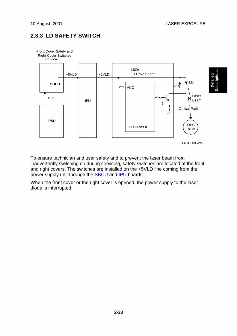
10 August, 2001 LASER EXPOSURE
2-23
Det
aile
dD
escr
iptio
ns
2.3.3 LD SAFETY SWITCH
To ensure technician and user safety and to prevent the laser beam frominadvertently switching on during servicing, safety switches are located at the frontand right covers. The switches are installed on the +5VLD line coming from thepower supply unit through the SBCU and IPU boards.When the front cover or the right cover is opened, the power supply to the laserdiode is interrupted.
IPU
PSU
Front Cover Safety andRight Cover Switches
SBCU
+5V
+5VLD+5VLDLDD:LD Drive Board
VCC
LD Driver IC
LaserBeam
OPCDrum
Optical Path
PDLD
B027D500.WMF
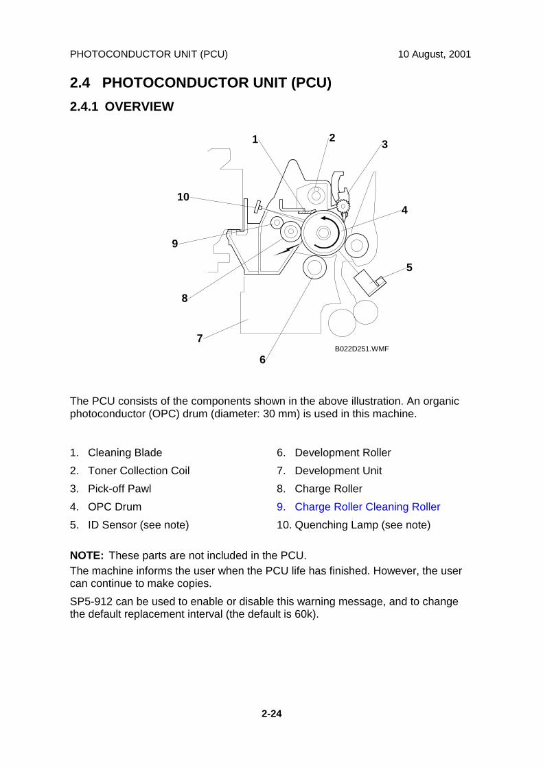
PHOTOCONDUCTOR UNIT (PCU) 10 August, 2001
2-24
2.4 PHOTOCONDUCTOR UNIT (PCU)2.4.1 OVERVIEW
The PCU consists of the components shown in the above illustration. An organicphotoconductor (OPC) drum (diameter: 30 mm) is used in this machine.
1. Cleaning Blade2. Toner Collection Coil3. Pick-off Pawl4. OPC Drum5. ID Sensor (see note)
6. Development Roller7. Development Unit8. Charge Roller9. Charge Roller Cleaning Roller10. Quenching Lamp (see note)
NOTE: These parts are not included in the PCU.The machine informs the user when the PCU life has finished. However, the usercan continue to make copies.SP5-912 can be used to enable or disable this warning message, and to changethe default replacement interval (the default is 60k).
B022D251.WMF
1 2 3
4
5
6
7
8
9
10
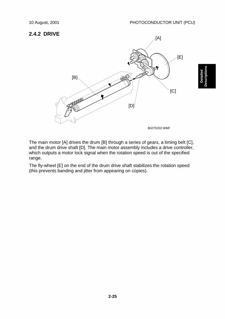
10 August, 2001 PHOTOCONDUCTOR UNIT (PCU)
2-25
Det
aile
dD
escr
iptio
ns
2.4.2 DRIVE
The main motor [A] drives the drum [B] through a series of gears, a timing belt [C],and the drum drive shaft [D]. The main motor assembly includes a drive controller,which outputs a motor lock signal when the rotation speed is out of the specifiedrange.The fly-wheel [E] on the end of the drum drive shaft stabilizes the rotation speed(this prevents banding and jitter from appearing on copies).
B027D202.WMF
[A]
[B]
[C]
[D]
[E]

PHOTOCONDUCTOR UNIT (PCU) 10 August, 2001
2-26
2.4.3 NEW PCU DETECTION
The new PCU detect switch [A] detects when a new PCU is installed. Each PCUhas an actuator [B]. When a new PCU is installed in the machine, the actuator [B]pushes the new PCU detect switch. The actuator is a sector gear, and this gearengages with the drum gear [C]. When the drum rotates, the actuator is releasedfrom the drum gear. The actuator drops away from the new PCU detect switch andremains in this "down" position for the duration of the PCU's life.The machine recognizes when a new PCU has been installed in the machinebecause the actuator of the new PCU contacts the new PCU detect switch. Afterthe front cover and right cover are closed, the machine then performs the TDsensor initial setting procedure automatically (for about 45 seconds). During thistime, the drum rotates and the actuator drops away from the sensor.Also, while the machine performs the TD sensor initial setting, the machine makesa ID sensor pattern on the drum. This checks whether the developer has fallen intothe development unit (in other words, it checks whether the technician rememberedto remove the developer seal from the PCU at machine installation). If the machinedoes not detect the ID sensor pattern, SC 392 will be generated.
B027D206.WMF
[A]
[B] [C]
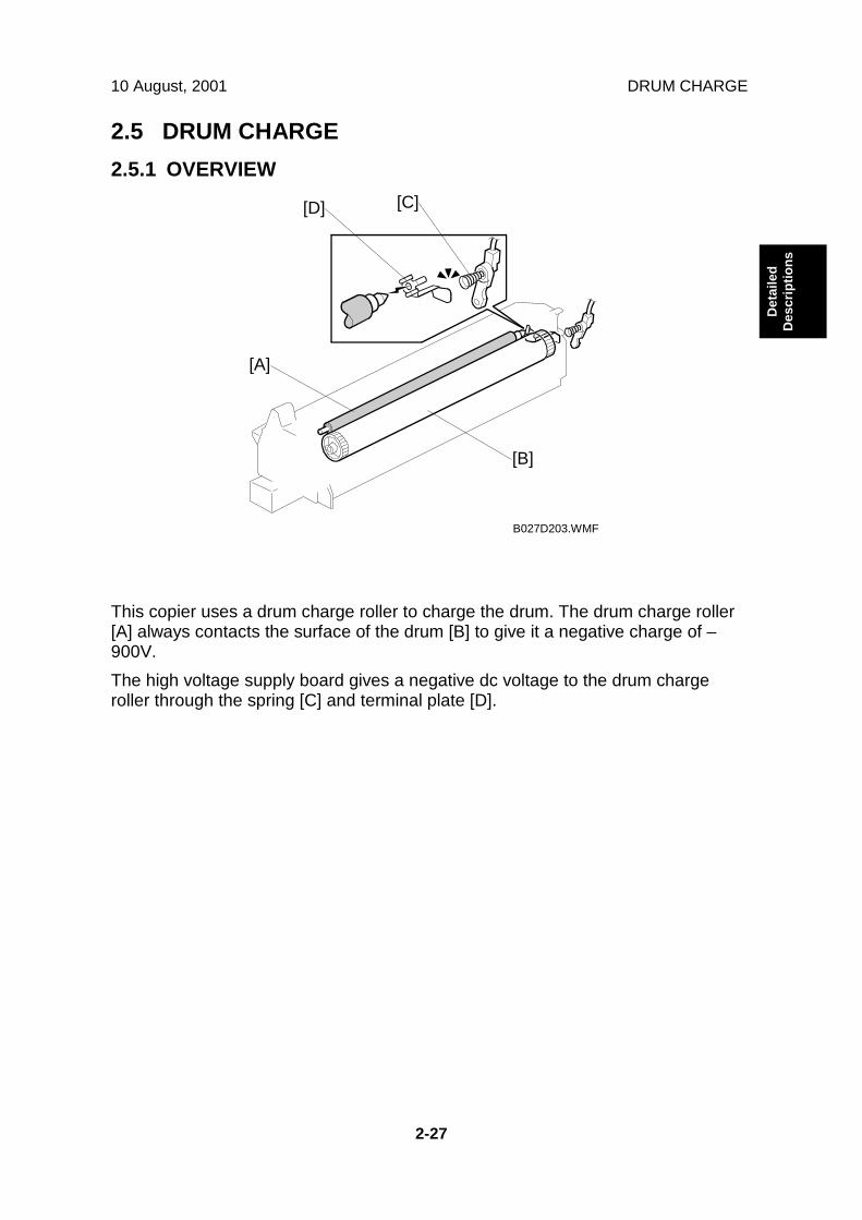
10 August, 2001 DRUM CHARGE
2-27
Det
aile
dD
escr
iptio
ns
2.5 DRUM CHARGE2.5.1 OVERVIEW
This copier uses a drum charge roller to charge the drum. The drum charge roller[A] always contacts the surface of the drum [B] to give it a negative charge of –900V.The high voltage supply board gives a negative dc voltage to the drum chargeroller through the spring [C] and terminal plate [D].
B027D203.WMF
[A]
[B]
[C][D]
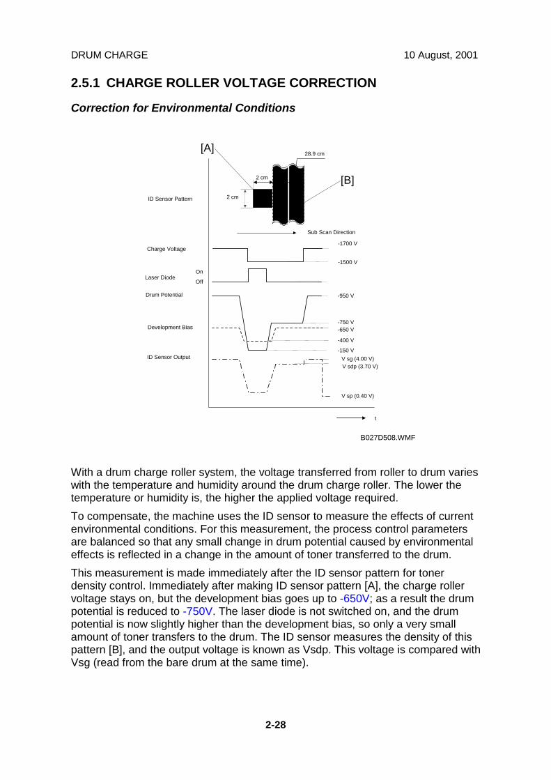
DRUM CHARGE 10 August, 2001
2-28
2.5.1 CHARGE ROLLER VOLTAGE CORRECTION
Correction for Environmental Conditions
With a drum charge roller system, the voltage transferred from roller to drum varieswith the temperature and humidity around the drum charge roller. The lower thetemperature or humidity is, the higher the applied voltage required.To compensate, the machine uses the ID sensor to measure the effects of currentenvironmental conditions. For this measurement, the process control parametersare balanced so that any small change in drum potential caused by environmentaleffects is reflected in a change in the amount of toner transferred to the drum.This measurement is made immediately after the ID sensor pattern for tonerdensity control. Immediately after making ID sensor pattern [A], the charge rollervoltage stays on, but the development bias goes up to -650V; as a result the drumpotential is reduced to -750V. The laser diode is not switched on, and the drumpotential is now slightly higher than the development bias, so only a very smallamount of toner transfers to the drum. The ID sensor measures the density of thispattern [B], and the output voltage is known as Vsdp. This voltage is compared withVsg (read from the bare drum at the same time).
Drum Potential
Development Bias
ID Sensor Output
+
ID Sensor Pattern
t
-950 V
-750 V-650 V
-400 V
-150 VV sg (4.00 V)V sdp (3.70 V)
V sp (0.40 V)
Charge Voltage
Laser Diode
2 cm
On
Off
-1700 V
Sub Scan Direction
-1500 V
28.9 cm
2 cm
B027D508.WMF
[A]
[B]

10 August, 2001 DRUM CHARGE
2-29
Det
aile
dD
escr
iptio
ns
If the humidity drops, the drum potential goes up (to a higher –ve voltage) even ifthe charge roller voltage supply stays the same (efficiency of voltage transfer ishigher with lower humidity). As a result, less toner is transferred to ID sensorpattern [B]. If the sensor output reaches a certain point, the drum charge voltagewill be reduced.To determine whether to change the drum charge roller voltage, the machinecompares Vsdp with Vsg.• Vsdp / Vsg > 0.95 = Reduce the magnitude of the drum charge voltage by 50 V• Vsdp / Vsg < 0.90 = Increase the magnitude of the drum charge voltage by 50 V
2.5.2 ID SENSOR PATTERN PRODUCTION TIMING
The ID sensor pattern is made in the following conditions:• During warming up at power on• If the machine starts warming up after a certain time (default: 30 minutes) has
passed since entering night mode or low power modeThe 30-minute interval can be changed using SP2995-1.
• At the end of a job, if an ID sensor pattern has not been made for a certainnumber of sheets (default: 0 sheets = disabled)The number of sheets can be changed using SP2995-2.

DRUM CHARGE 10 August, 2001
2-30
2.5.3 DRUM CHARGE ROLLER CLEANING
Because the drum charge roller [A] always contacts the drum, it gets dirty easily.So, the charge roller cleaning roller [B] also contacts the drum charge roller all thetime to clean the surface of the drum charge roller.
B022D252.WMF
[A]
[B]
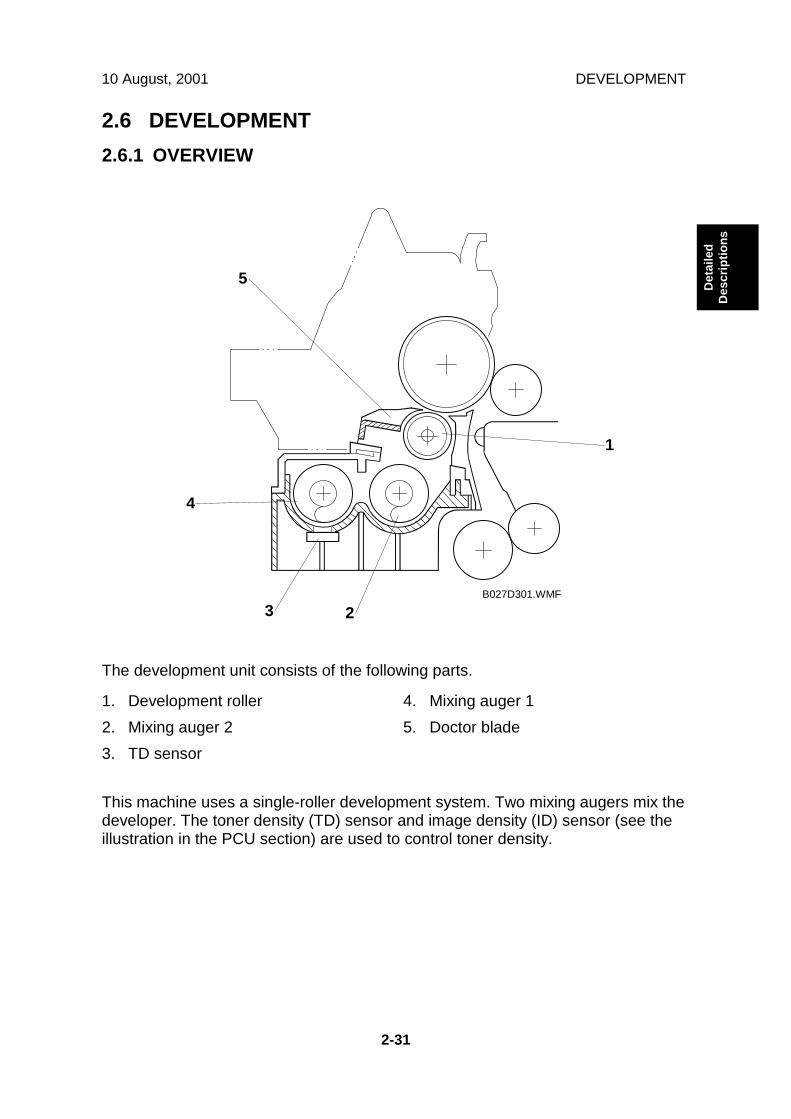
10 August, 2001 DEVELOPMENT
2-31
Det
aile
dD
escr
iptio
ns
2.6 DEVELOPMENT2.6.1 OVERVIEW
The development unit consists of the following parts.
1. Development roller2. Mixing auger 23. TD sensor
4. Mixing auger 15. Doctor blade
This machine uses a single-roller development system. Two mixing augers mix thedeveloper. The toner density (TD) sensor and image density (ID) sensor (see theillustration in the PCU section) are used to control toner density.
B027D301.WMF
1
23
4
5
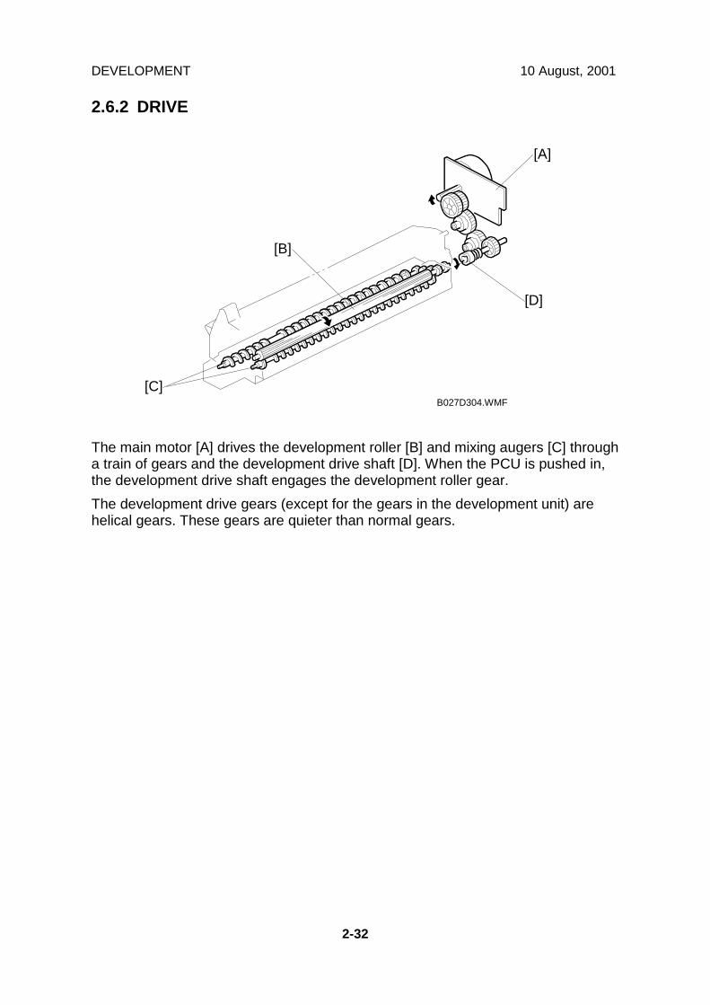
DEVELOPMENT 10 August, 2001
2-32
2.6.2 DRIVE
The main motor [A] drives the development roller [B] and mixing augers [C] througha train of gears and the development drive shaft [D]. When the PCU is pushed in,the development drive shaft engages the development roller gear.The development drive gears (except for the gears in the development unit) arehelical gears. These gears are quieter than normal gears.
B027D304.WMF
[A]
[B]
[C]
[D]
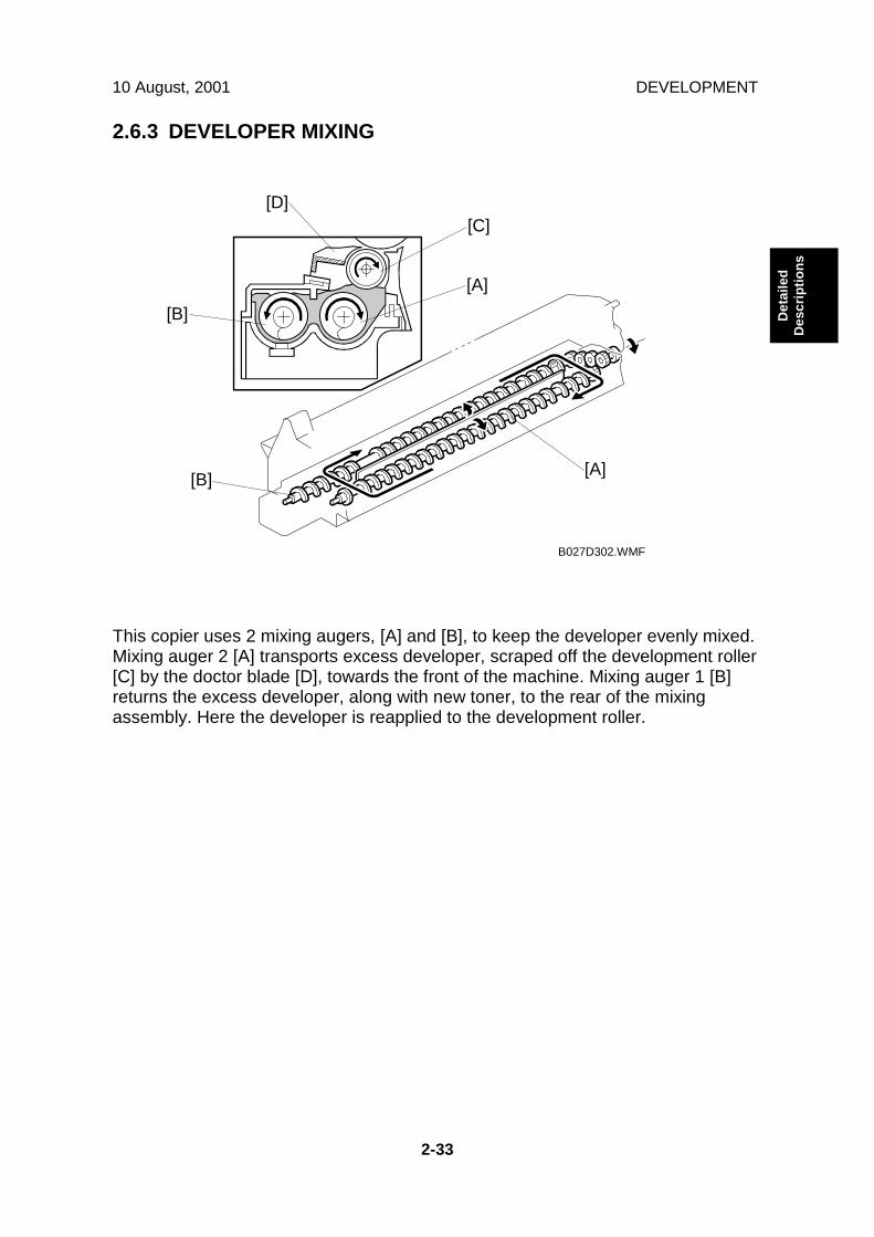
10 August, 2001 DEVELOPMENT
2-33
Det
aile
dD
escr
iptio
ns
2.6.3 DEVELOPER MIXING
This copier uses 2 mixing augers, [A] and [B], to keep the developer evenly mixed.Mixing auger 2 [A] transports excess developer, scraped off the development roller[C] by the doctor blade [D], towards the front of the machine. Mixing auger 1 [B]returns the excess developer, along with new toner, to the rear of the mixingassembly. Here the developer is reapplied to the development roller.
B027D302.WMF
[A][B]
[C][D]
[A][B]

DEVELOPMENT 10 August, 2001
2-34
2.6.4 DEVELOPMENT BIAS
This machine uses a negative-positive development system, in which black areasof the latent image are at a low negative charge (about –150 ± 50 V) and whiteareas are at a high negative charge (about -950 V).To attract negatively charged toner to the black areas of the latent image on thedrum, the high voltage supply board applies a bias of -650 volts to the developmentrollers throughout the image development process. The bias is applied to thedevelopment roller shaft [A] through the drive shaft [B].The development bias voltage (-650 V) can be adjusted with SP2-201-1.
B027D303.WMF
[A]
[B]

10 August, 2001 DEVELOPMENT
2-35
Det
aile
dD
escr
iptio
ns
2.6.5 TONER SUPPLY
Toner bottle replenishment mechanism
When a toner bottle is placed in the bottle holder unit [A] and the unit is pushed incompletely, pin [B] moves against the side [C] of the PCU, and the toner shutter [D]is pulled out to open the bottle. When the toner bottle holder lever [E] is put back inthe original position, the cap [F] on the toner bottle is pulled away and kept in placeby the chuck [G].The toner supply mechanism transports toner from the bottle to the developmentunit. The toner bottle has a spiral groove [H] that helps move toner to thedevelopment unit.When the bottle holder unit is pulled out to add a new toner bottle, the followinghappens automatically to prevent toner from scattering.• The chuck releases the toner bottle cap into its proper position.• The toner shutter shuts to block the opening as a result of pressure from a
spring.
B027D557.WMF[A][B]
[C]
[D]
[E]
[F][G]
[H]
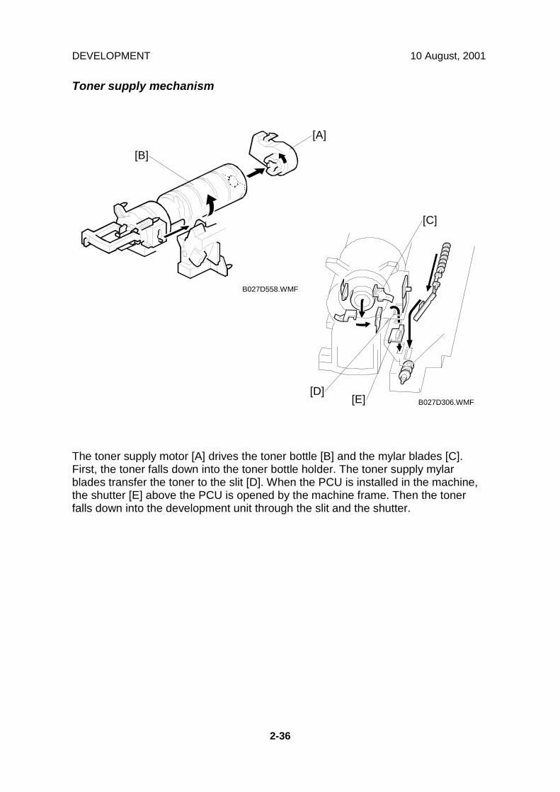
DEVELOPMENT 10 August, 2001
2-36
Toner supply mechanism
The toner supply motor [A] drives the toner bottle [B] and the mylar blades [C].First, the toner falls down into the toner bottle holder. The toner supply mylarblades transfer the toner to the slit [D]. When the PCU is installed in the machine,the shutter [E] above the PCU is opened by the machine frame. Then the tonerfalls down into the development unit through the slit and the shutter.
B027D558.WMF
B027D306.WMF
[A]
[B]
[C]
[D][E]
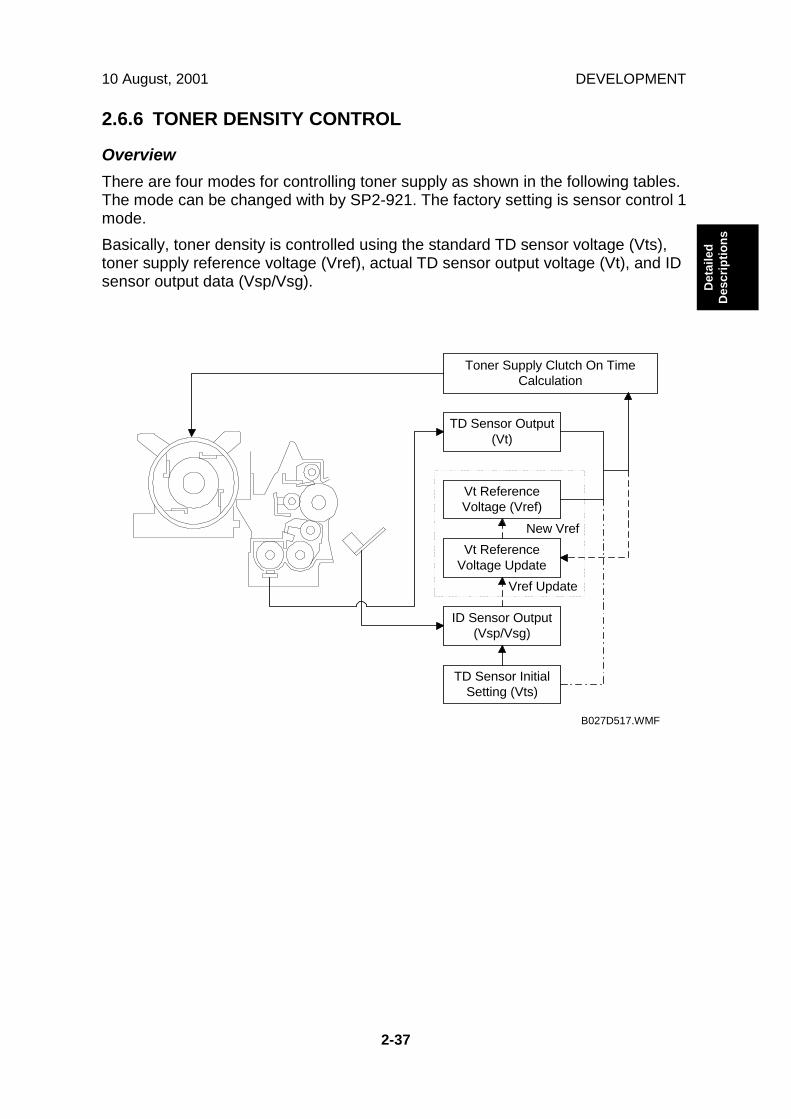
10 August, 2001 DEVELOPMENT
2-37
Det
aile
dD
escr
iptio
ns
2.6.6 TONER DENSITY CONTROL
OverviewThere are four modes for controlling toner supply as shown in the following tables.The mode can be changed with by SP2-921. The factory setting is sensor control 1mode.Basically, toner density is controlled using the standard TD sensor voltage (Vts),toner supply reference voltage (Vref), actual TD sensor output voltage (Vt), and IDsensor output data (Vsp/Vsg).
TD Sensor InitialSetting (Vts)
ID Sensor Output(Vsp/Vsg)
Vt ReferenceVoltage Update
Vt ReferenceVoltage (Vref)
TD Sensor Output(Vt)
Toner Supply Clutch On TimeCalculation
New Vref
Vref Update
B027D517.WMF

DEVELOPMENT 10 August, 2001
2-38
There are four toner density control modes as follows.
Mode Sensor control 1 (SP2-921, “0”): Normally use this setting onlyToner supply decision Compare Vt with a reference voltage (Vts or Vref)Toner control process Toner is supplied to the development unit when Vt is higher
than the reference voltage (Vts or Vref). This mode keeps theVref value for use the next toner density control.
Vts is used for the first toner density control after a new PCUhas been installed, until it has been corrected with the IDsensor output.Vref is used after Vts has been corrected with the ID sensoroutput voltage (corrected during the first toner density controlfor a new PCU).
Toner supply amount VariesToner end detection Performed
Mode Sensor control 2 (SP2-921, “1”): For designer’s use only; donot use in the field
Toner supply decision Compare Vt with a reference voltage (Vts)Toner control process This toner control process is the same as sensor control 1
mode. However, the reference voltage used is always Vts.Toner supply amount VariesToner end detection Performed
Mode Fixed control 1 (SP2-921, “2”): For designer’s use only; do notuse in the field
Toner supply decision Compare Vt with a reference voltage (Vts or Vref)Toner control process This toner control process is the same as sensor control 1
mode.Toner supply amount Fixed (SP2-925)Toner end detection Performed
Mode Fixed control 2 (SP2-921, “3”): Use temporarily if the TDsensor needs to be replaced
Toner supply decision NoneToner control process Toner is supplied every printed page regardless of Vt.Toner supply amount Fixed (SP2-925)Toner end detection Not performed
10 August, 2001 DEVELOPMENT
2-39
Det
aile
dD
escr
iptio
ns
Toner density sensor initial settingThe TD sensor initial setting procedure is performed automatically when the newPCU is installed in the machine. During TD sensor initial setting, the TD sensor isset so that the TD sensor output to the value of SP2-926 (default: 2.5V). This valuewill be used as the standard reference voltage (Vts) of the TD sensor.
Toner density measurementToner density in the developer is detected once every copy cycle. The sensoroutput voltage (Vt) during the detection cycle is compared with the standardreference voltage (Vts) or the toner supply reference voltage (Vref).
Vsp/Vsg detectionThe ID sensor detects the following voltages.
• Vsg: The ID sensor output when checking the drum surface• Vsp: The ID sensor output when checking the ID sensor pattern• At the end of a job, if an ID sensor pattern has not been made for a certain
number of sheets (default: 0 sheets = disabled)The number of sheets can be changed using SP2-995-2.
In this way, the reflectivity of both the drum surface and the pattern on the drum arechecked. This compensates for any variations in the reflectivity of the pattern onthe drum or the reflectivity of the drum surface.The ID sensor pattern is made on the drum by charge roller and laser diode.Vsp/Vsg is not detected every page or job; it is detected at the following times todecide Vref.
• During warming up at power on• If the machine starts warming up after a certain time (default: 30 minutes)
has passed since entering night mode or low power modeThe 30-minute interval can be changed using SP2-995.
Toner supply reference voltage (Vref) determinationThe toner supply reference voltage (Vref) is the threshold voltage for the tonersupply determination. Vref is determined using the following data:
• ID sensor output (Vsp/Vsg)• (Vts or the current Vref) - Vt
Toner supply determinationThe reference voltage (Vts or Vref) is the threshold voltage for determining whetheror not to supply toner. If Vt becomes greater than the reference voltage, themachine supplies additional toner.
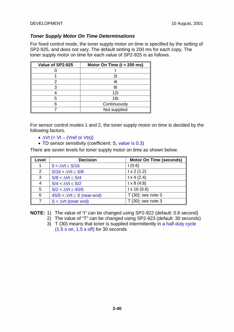
DEVELOPMENT 10 August, 2001
2-40
Toner Supply Motor On Time DeterminationsFor fixed control mode, the toner supply motor on time is specified by the setting ofSP2-925, and does not vary. The default setting is 200 ms for each copy. Thetoner supply motor on time for each value of SP2-925 is as follows.
Value of SP2-925 Motor On Time (t = 200 ms)0 t1 2t2 4t3 8t4 12t5 16t6 Continuously7 Not supplied
For sensor control modes 1 and 2, the toner supply motor on time is decided by thefollowing factors.
• ∆Vt (= Vt – (Vref or Vts))• TD sensor sensitivity (coefficient: S, value is 0.3)
There are seven levels for toner supply motor on time as shown below.
Level Decision Motor On Time (seconds)1 0 < ∆Vt ≤ S/16 t (0.6)2 S/16 < ∆Vt ≤ S/8 t x 2 (1.2)3 S/8 < ∆Vt ≤ S/4 t x 4 (2.4)4 S/4 < ∆Vt ≤ S/2 t x 8 (4.8)5 S/2 < ∆Vt ≤ 4S/5 t x 16 (9.6)6 4S/5 < ∆Vt ≤ S (near-end) T (30); see note 37 S < ∆Vt (toner end) T (30); see note 3
NOTE: 1) The value of “t” can be changed using SP2-922 (default: 0.6 second)2) The value of “T” can be changed using SP2-923 (default: 30 seconds)3) T (30) means that toner is supplied intermittently in a half duty cycle
(1.5 s on, 1.5 s off) for 30 seconds

10 August, 2001 DEVELOPMENT
2-41
Det
aile
dD
escr
iptio
ns
2.6.7 TONER SUPPLY IN ABNORMAL SENSOR CONDITIONS
ID sensorReadings are abnormal if any of the following conditions occur:
• Vsg ≤ 2.5V• Vsg < 3.5V when maximum power (254) is applied• Vsp ≥ 2.5V• (Vsg – Vsp) < 1.0V• ID sensor power required to make the standard output reaches the maximum
value (254)The above ID sensor values can be checked using SP2-220.When this is detected, the machine changes the value of Vref to the previous valuethen does the toner density control process (in a similar way to sensor controlmode 2).No SC code is generated if the ID sensor is defective.TD SensorThe TD sensor is checked every copy. If the readings from TD sensor becomeabnormal, the machine changes the toner density control mode to fixed supplymode 2, and the toner supply amount per page is always 200 ms, regardless of thevalue of SP2-925. Then at the end of a job (if the optional fax unit is installed), or100 copies after the TD sensor error was detected (if no fax unit is installed), an SCcode is generated (SC390) and the machine must be repaired. The 100-copythreshold can be adjusted with SP 2-992.
2.6.8 TONER NEAR END/END DETECTION AND RECOVERY
The toner near end and end conditions are detected using the Vt and Vref values,in a similar way to toner density control.This is done in all toner supply modes except for fixed mode 2, when toner end isnot detected.
Toner Near End DetectionIf Vt is at level 6 (see the table on the previous page) five times consecutively, themachine enters the toner near end condition and the toner end indicator startsblinking. Then the machine supplies toner for a certain time, which depends on thesetting of SP 2-923 (see the previous page).
DEVELOPMENT 10 August, 2001
2-42
Toner Near End RecoveryIf the machine detects “S/2 < ∆Vt ≤ 4S/5” twice consecutively when in one of thefollowing situations, the machine leaves the toner near end condition.
• While in the toner recovery cycle (supplying toner on and off for 30 s – seethe previous page) after the machine has detected a toner near endcondition.
• During copying in the toner near end condition.• If the front cover is opened and closed for more than 10 seconds while a
toner near end condition exists.
Toner End DetectionThere are two situations for entering the toner end condition.
• When Vt is level 7 three times consecutively, the machine enters the tonerend condition.
• When “4S/5 < ∆Vt ≤ S” is detected in the toner near end condition, then 50copies can be made after this condition (the number of copies between thiscondition and toner end can be changed using SP2-213).
Toner End RecoveryIf the front cover is opened and closed for 10 seconds while a toner end conditionexists and the toner bottle is replaced, the machine attempts to recover using thesame procedure as for toner near end/end detection.
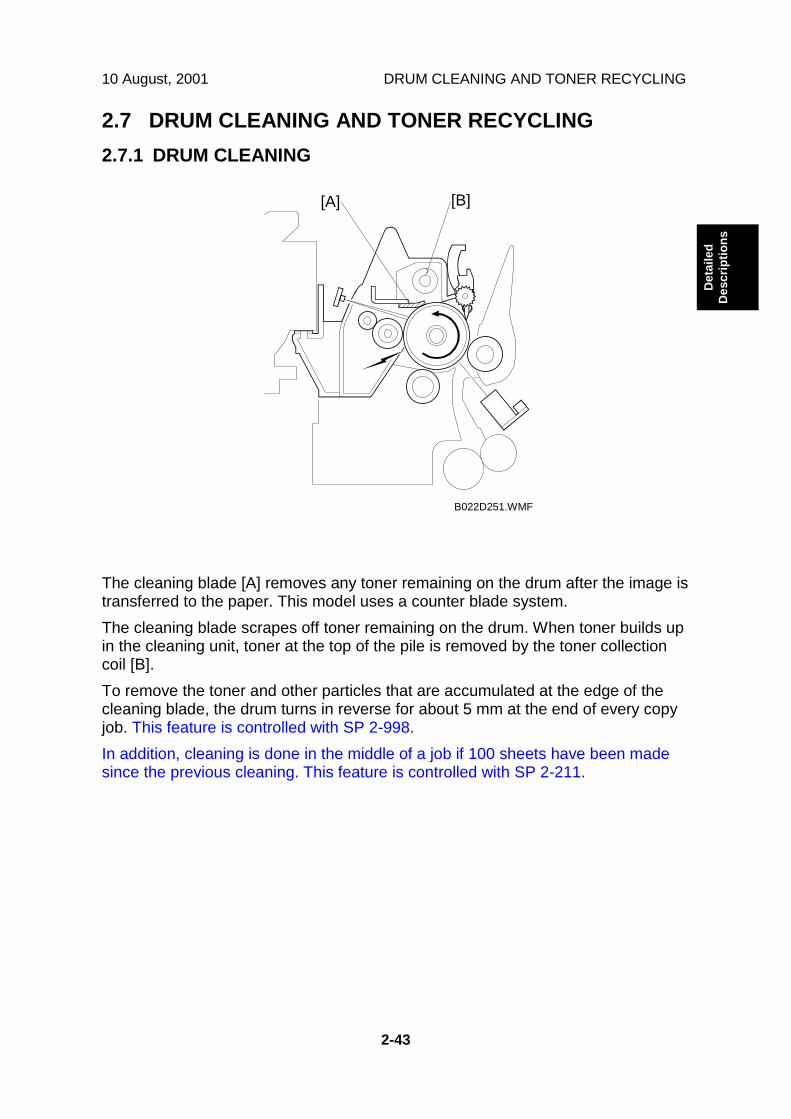
10 August, 2001 DRUM CLEANING AND TONER RECYCLING
2-43
Det
aile
dD
escr
iptio
ns
2.7 DRUM CLEANING AND TONER RECYCLING2.7.1 DRUM CLEANING
The cleaning blade [A] removes any toner remaining on the drum after the image istransferred to the paper. This model uses a counter blade system.The cleaning blade scrapes off toner remaining on the drum. When toner builds upin the cleaning unit, toner at the top of the pile is removed by the toner collectioncoil [B].To remove the toner and other particles that are accumulated at the edge of thecleaning blade, the drum turns in reverse for about 5 mm at the end of every copyjob. This feature is controlled with SP 2-998.In addition, cleaning is done in the middle of a job if 100 sheets have been madesince the previous cleaning. This feature is controlled with SP 2-211.
B022D251.WMF
[A] [B]

DRUM CLEANING AND TONER RECYCLING 10 August, 2001
2-44
2.7.2 TONER RECYCLING
Toner picked up by the toner collection coil [A], is transported to the opening [B] inthe side of the PCU. Then, this toner falls into the development unit with new tonercoming from the toner bottle and it is all mixed together by mixing auger 1 [C] andused again.
B027D205.WMF
B027D306.WMF
[A]
[B]
[A]
[B]
[C]

10 August, 2001 PAPER FEED
2-45
Det
aile
dD
escr
iptio
ns
2.8 PAPER FEED2.8.1 OVERVIEW
There are two paper trays, each of which can hold 500 sheets.The paper tray feed stations use a friction pad system.The two relay sensors are used for paper jam detection.The components of the paper feed station are as follows.
1. Paper Lift Sensor2. Paper Height –1 Sensor3. Paper Height –2 Sensor4. Paper End Sensor5. Paper Feed Roller6. Paper Size Sensor
7. Upper Relay Sensor8. Upper Relay Roller9. Lower Relay Roller10. Lower Relay Sensor11. Friction Pad12. Tray Heater (Option)
B027D501.WMF
1 2 3 4 5
6
8
9
101112
7

PAPER FEED 10 August, 2001
2-46
2.8.2 PAPER FEED DRIVE MECHANISM
The main motor [A] drives the pick-up and feed mechanism of both the first andsecond paper trays. The paper feed clutches [B] transfer drive from this motor tothe paper feed rollers [C].When the paper feed clutch turns on, the feed rollers start to feed the paper. Thepaper feed clutch stays on until shortly after the registration sensor [D] has beenactivated.
B027D702.WMF
[A]
[B]
[C]
[D]
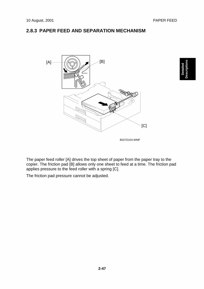
10 August, 2001 PAPER FEED
2-47
Det
aile
dD
escr
iptio
ns
2.8.3 PAPER FEED AND SEPARATION MECHANISM
The paper feed roller [A] drives the top sheet of paper from the paper tray to thecopier. The friction pad [B] allows only one sheet to feed at a time. The friction padapplies pressure to the feed roller with a spring [C].The friction pad pressure cannot be adjusted.
B027D104.WMF
[B][A]
[C]

PAPER FEED 10 August, 2001
2-48
2.8.4 PAPER LIFT MECHANISM
The paper size switch detects when the tray is pushed in.When the paper tray is pushed into the machine, the pin [A] for the lift motorpressure shaft engages the lift motor coupling [B] and the pin [C] for the bottomplate lift shaft in the tray engages the bottom plate pressure lever coupling [D]. Thepin [E] on the rear of the tray pushes the lock lever so that the lift motor can lift thebottom plate pressure lever.The lift motor turns on, and turns clockwise as shown in the diagram. The mainpressure spring [K] pulls the bottom plate pressure lever, and this lifts the traybottom plate.When the top of the stack touches the feed roller, the motor cannot pull up theplate any more, so it pulls the actuator [G] into the lift sensor [F]. Then the lift motorstops. The pressure of the feed roller on the paper is now too high, so the lift motorreverses a certain time (200 ms or 600 ms), depending on the paper size, toreduce this pressure. For smaller paper, it reverses the larger amount (600 ms) toreduce the pressure more.NOTE: The relationship between the bottom plate pressure adjustment, paper size
thresholds, and the related SP modes is explained in “Bottom PlatePressure Adjustment for Paper Size”.
B027D521.WMF
B027D522.WMF
[A][B]
[D]
[C]
[D]
[B]
[A]
[I][J]
[E]
[C]
[E]
[H]
[K] [G] [F]
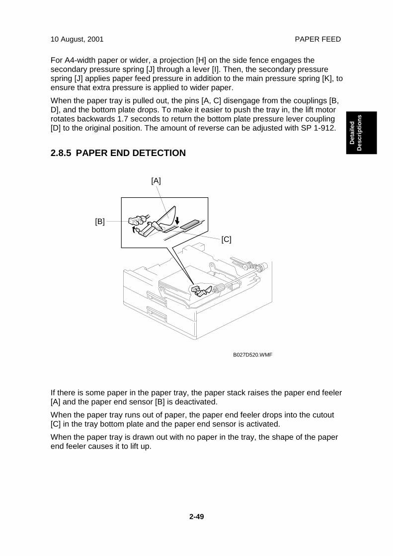
10 August, 2001 PAPER FEED
2-49
Det
aile
dD
escr
iptio
ns
For A4-width paper or wider, a projection [H] on the side fence engages thesecondary pressure spring [J] through a lever [I]. Then, the secondary pressurespring [J] applies paper feed pressure in addition to the main pressure spring [K], toensure that extra pressure is applied to wider paper.When the paper tray is pulled out, the pins [A, C] disengage from the couplings [B,D], and the bottom plate drops. To make it easier to push the tray in, the lift motorrotates backwards 1.7 seconds to return the bottom plate pressure lever coupling[D] to the original position. The amount of reverse can be adjusted with SP 1-912.
2.8.5 PAPER END DETECTION
If there is some paper in the paper tray, the paper stack raises the paper end feeler[A] and the paper end sensor [B] is deactivated.When the paper tray runs out of paper, the paper end feeler drops into the cutout[C] in the tray bottom plate and the paper end sensor is activated.When the paper tray is drawn out with no paper in the tray, the shape of the paperend feeler causes it to lift up.
B027D520.WMF
[A]
[C]
[B]

PAPER FEED 10 August, 2001
2-50
2.8.6 PAPER HEIGHT DETECTION
The amount of paper in the tray is detected by the combination of on/off signalsfrom two paper height sensors [A] and [B]. The paper amount is displayed on theLCD.When the amount of paper decreases, the bottom plate pressure lever [C] movesthe actuator up.The following combination of sensor signals is sent to the copier.
Amount of Paper Paper Height Sensor 1 Paper Height Sensor 2Near End OFF ON
30% ON ON 70% ON OFF100% OFF OFF
When the tray contains paper of a small width, the paper feed pressure maybecome too low when the thickness of the remaining stack of paper hasdecreased. The lift motor rotates forward 400 ms after the sensor detects a certainamount of paper remaining in the tray to increase paper feed pressure, simulatingthe pressure generated by a full tray.NOTE: The relationship between the bottom plate re-adjustment timing, paper size
threshold, and the related SP modes is explained in “Bottom PlatePressure Adjustment for Paper Size”.
B027D522.WMF
[C]
[C]
[B][A]
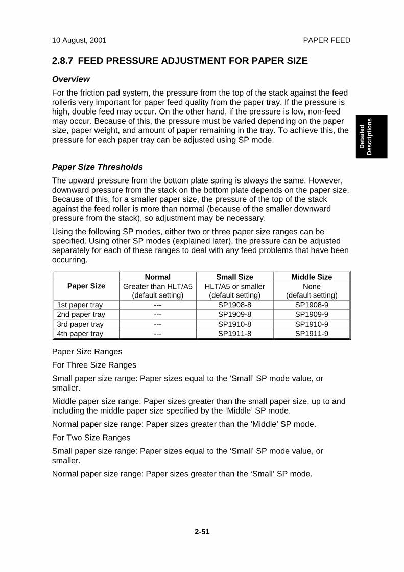
10 August, 2001 PAPER FEED
2-51
Det
aile
dD
escr
iptio
ns
2.8.7 FEED PRESSURE ADJUSTMENT FOR PAPER SIZE
OverviewFor the friction pad system, the pressure from the top of the stack against the feedrolleris very important for paper feed quality from the paper tray. If the pressure ishigh, double feed may occur. On the other hand, if the pressure is low, non-feedmay occur. Because of this, the pressure must be varied depending on the papersize, paper weight, and amount of paper remaining in the tray. To achieve this, thepressure for each paper tray can be adjusted using SP mode.
Paper Size ThresholdsThe upward pressure from the bottom plate spring is always the same. However,downward pressure from the stack on the bottom plate depends on the paper size.Because of this, for a smaller paper size, the pressure of the top of the stackagainst the feed roller is more than normal (because of the smaller downwardpressure from the stack), so adjustment may be necessary.Using the following SP modes, either two or three paper size ranges can bespecified. Using other SP modes (explained later), the pressure can be adjustedseparately for each of these ranges to deal with any feed problems that have beenoccurring.
Normal Small Size Middle SizePaper Size Greater than HLT/A5
(default setting)HLT/A5 or smaller
(default setting)None
(default setting)1st paper tray --- SP1908-8 SP1908-92nd paper tray --- SP1909-8 SP1909-93rd paper tray --- SP1910-8 SP1910-94th paper tray --- SP1911-8 SP1911-9
Paper Size RangesFor Three Size RangesSmall paper size range: Paper sizes equal to the ‘Small’ SP mode value, orsmaller.Middle paper size range: Paper sizes greater than the small paper size, up to andincluding the middle paper size specified by the ‘Middle’ SP mode.Normal paper size range: Paper sizes greater than the ‘Middle’ SP mode.For Two Size RangesSmall paper size range: Paper sizes equal to the ‘Small’ SP mode value, orsmaller.Normal paper size range: Paper sizes greater than the ‘Small’ SP mode.
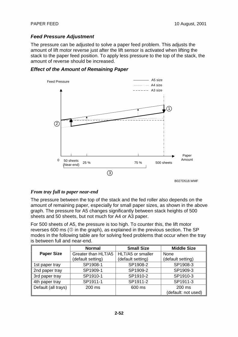
PAPER FEED 10 August, 2001
2-52
Feed Pressure AdjustmentThe pressure can be adjusted to solve a paper feed problem. This adjusts theamount of lift motor reverse just after the lift sensor is activated when lifting thestack to the paper feed position. To apply less pressure to the top of the stack, theamount of reverse should be increased.Effect of the Amount of Remaining Paper
From tray full to paper near-endThe pressure between the top of the stack and the fed roller also depends on theamount of remaining paper, especially for small paper sizes, as shown in the abovegraph. The pressure for A5 changes significantly between stack heights of 500sheets and 50 sheets, but not much for A4 or A3 paper.For 500 sheets of A5, the pressure is too high. To counter this, the lift motorreverses 600 ms (! in the graph), as explained in the previous section. The SPmodes in the following table are for solving feed problems that occur when the trayis between full and near-end.
Normal Small Size Middle SizePaper Size Greater than HLT/A5
(default setting)HLT/A5 or smaller(default setting)
None(default setting)
1st paper tray SP1908-1 SP1908-2 SP1908-32nd paper tray SP1909-1 SP1909-2 SP1909-33rd paper tray SP1910-1 SP1910-2 SP1910-34th paper tray SP1911-1 SP1911-2 SP1911-3Default (all trays) 200 ms 600 ms 200 ms
(default: not used)
PaperAmount
Feed Pressure
500 sheets75 %25 %50 sheets(Near-end)
0
1
2
3
A5 sizeA4 sizeA3 size
B027D518.WMF

10 August, 2001 PAPER FEED
2-53
Det
aile
dD
escr
iptio
ns
From paper near end to paper endWhen paper is used up, the pressure on the bottom plate reduces, so the upwardpressure increases, causing the pressure of the feed roller against the top of thestack to increase.However, for small paper sizes, because of the previous correction (600 msreverse rotation of the lift motor), the pressure between the feed roller and the topof the stack becomes too small at some point as paper is used up, and this couldcause paper feed problems. This condition is more significant for smaller papersizes, such as A5, as shown in the diagram.If a paper feed problem occurs when the stack is partly used up, the pressure canbe re-adjusted (" in the graph) using the following SP modes. The default is set for50 sheets (at the near-end point)The lift motor rotates forward for the time specified by the SP mode to increase thepressure.
Small Size Middle SizePaper Size HLT/A5 or smaller
(default setting)None
(default setting)1st paper tray SP1908-4 SP1908-52nd paper tray SP1909-4 SP1909-53rd paper tray SP1910-4 SP1910-54th paper tray SP1911-4 SP1911-5Default (all trays) 400 ms 300 ms
(default: not used)
Also, the point at which this adjustment is applied (near-end [50 sheets], 25% full,75% full) can be selected (# in the graph) using the following SP modes.
Small Size Middle SizePaper Size HLT/A5 or smaller
(default setting)None
(default setting)1st paper tray SP1908-6 SP1908-72nd paper tray SP1909-6 SP1909-73rd paper tray SP1910-6 SP1910-74th paper tray SP1911-6 SP1911-7Default (all trays) Near-end Near-end
(default: not used)

PAPER FEED 10 August, 2001
2-54
2.8.8 PAPER SIZE DETECTION
There are four paper size microswitches [A] on the front right plate of the paper trayunit. The switches are actuated by a paper size actuator [B] behind the paper sizeindicator plate, which is on the front right of the tray.Each paper size has its own actuator, with a unique combination of notches. Todetermine which size has been installed, the CPU reads which microswitches theactuator has switched off.The CPU disables paper feed from a tray if the paper size cannot be detected. Ifthe paper size actuator is broken, or if there is no tray installed, the Add Paperindicator will light.When the paper size actuator is at the “*” mark, the paper tray can be set up toaccommodate one of a wider range of paper sizes by using user tools. If the papersize for this position is changed without changing the user tool setting, a paper jamwill result.
B027D523.WMF
SWSize 1 2 3 4
A3 ❍ ❍ ❍ ❍
A4 Sideways # # ❍ #
A4 Lengthwise # # ❍ ❍
A5 Lengthwise,81/2" x 14" ❍ ❍ # #
B4, 11" x 17" # ❍ # ❍
B5 Sideways,11" x 81/2"
# ❍ ❍ ❍
B5 Lengthwise,81/2" x 11" ❍ # # #
* (Asterisk) ❍ # ❍ #
#: ON (Not pushed)❍: OFF (Pushed)
[A]
[B]

10 August, 2001 PAPER FEED
2-55
Det
aile
dD
escr
iptio
ns
2.8.9 SPECIAL PAPER SETTING
Only the 2nd tray can feed special paper such as thick paper or envelopes. Thespecial paper type can be selected either by using the UP mode or with thefollowing operation.
• Select the 2nd tray then press the ! key.
After selecting the special paper type, the fusing temperature and transfer rollercurrent will be changed as follows.
1. Fusing temperature (when thick paper is selected):Current operation temperature + 15 °C
2. Transfer roller current:A3 width (11”): 14 µA
B4 width (10”): 15 µA
A4 width (8.5”): 17 µA
A5 width (5.5”): 20 µANote that for the by-pass tray, the fusing and transfer conditions for special paperare also applied if the user uses thick (non-standard) mode.
B027D590.WMF

PAPER FEED 10 August, 2001
2-56
2.8.10 SIDE AND END FENCES
Side FencesIf the tray is full of paper and it is pushed in strongly, the fences may deform orbend. This may cause the paper to skew or the side-to-side registration to beincorrect. To correct this, each side fence has a stopper [A] attached to it. Eachside fence can be secured with a screw [B], for customers who do not want tochange the paper size.
End FenceAs the amount of paper in the tray decreases, the bottom plate [C] lifts upgradually. The end fence [D] is connected to the bottom plate. When the traybottom plate rises, the end fence moves forward and pushes the back of the paperstack to keep it squared up.
B027D110.WMF
B027D109.WMF
[A]
[D]
[C]
[B]

10 August, 2001 PAPER FEED
2-57
Det
aile
dD
escr
iptio
ns
2.8.11 PAPER REGISTRATION
The drive from the main motor [A] is transmitted to the registration roller throughthe registration clutch gear [B].The registration sensor [C] is used for correcting paper skew and for detectingpaper misfeeds.The cleaning mylar [D] contacts the registration roller. It removes paper dust fromthe registration roller so that this dust will not transfer into the development unitthrough the drum cleaning unit.The amount of paper buckle at the registration roller to correct skew can beadjusted with SP 1003.If jams frequently occur after registration, the paper feed clutch can be re-energized so that the feed roller can assist the registration roller to re-start paperfeed. This may be needed when feeding thicker paper. This adjustment is madewith SP 1903; it can be adjusted separately for tray 1 and the by-pass feeder, soplace the problem paper type in one of these and adjust SP 1-903 for that trayonly.
B027D702.WMF
B022D704.WMF
[A]
[B]
[C]
[D]
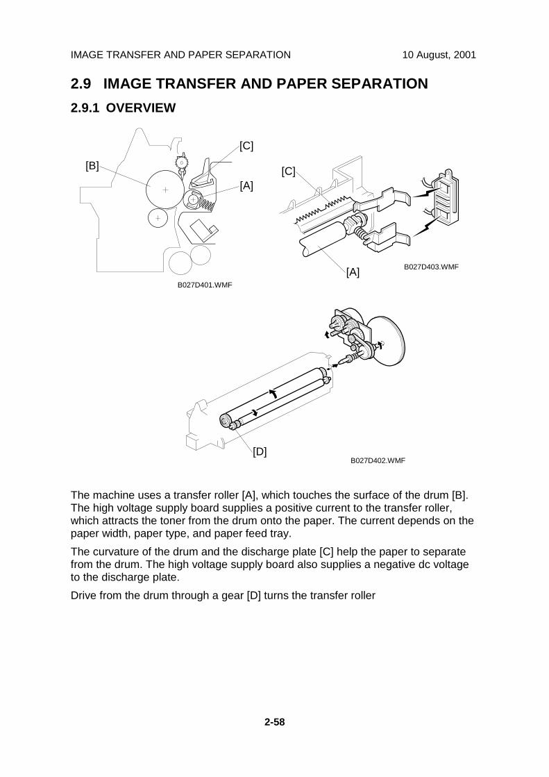
IMAGE TRANSFER AND PAPER SEPARATION 10 August, 2001
2-58
2.9 IMAGE TRANSFER AND PAPER SEPARATION2.9.1 OVERVIEW
The machine uses a transfer roller [A], which touches the surface of the drum [B].The high voltage supply board supplies a positive current to the transfer roller,which attracts the toner from the drum onto the paper. The current depends on thepaper width, paper type, and paper feed tray.The curvature of the drum and the discharge plate [C] help the paper to separatefrom the drum. The high voltage supply board also supplies a negative dc voltageto the discharge plate.Drive from the drum through a gear [D] turns the transfer roller
B027D401.WMF
B027D403.WMF
B027D402.WMF
[A]
[B]
[C]
[A]
[C]
[D]

10 August, 2001 IMAGE TRANSFER AND PAPER SEPARATION
2-59
Det
aile
dD
escr
iptio
ns
2.9.2 IMAGE TRANSFER CURRENT TIMING
There are two transfer current levels: low transfer current level and high transfercurrent level. The image transfer procedure is as follows:
1. When the CPU receives the image writing start signal, the CPU instructs thehigh voltage supply board to supply +10µA (low transfer current level) to theroller. This prevents any positively charged toner on the drum surface fromtransferring to the transfer roller.
2. At a certain time after the low transfer current has been supplied to the roller,an appropriate current is applied to the roller to transfer the toner to the paper.
3. After the trailing edge of the paper has passed through the roller, transfercurrent turns off. In multiple copy mode, the transfer current shifts again to thelow transfer current.
The transfer current (high transfer current level) depends on the paper feed station,paper width, and the temperature in the machine.
Example: Temperature = 15°C ~ 24°C
Paper WidthPaper Tray /By-pass Tray
(Normal)Duplex (2nd Side)
By-pass Tray(Thick) / 2ndPaper Tray
(Special Paper)A3/11” x 17”,A4/81/2 x 11”sideways 14 µA 10 µA 14 µA
B4 13 µA 12 µA 15 µAA4/11” x 81/2 lengthwise,A5/51/2 x 81/2 sidewise 13 µA 16 µA 17 µA
A5/81/2 x 51/2 lengthwiseand less 16 µA 16 µA 20 µA
The transfer current can be adjusted using SP2301, except for the low transfercurrent.Be careful when increasing the transfer current. This might cause a ghosting effect,in which part of the image at the top of the page is repeated lower down the pageat a lower density. It may also damage the OPC drum in the worst case.

IMAGE TRANSFER AND PAPER SEPARATION 10 August, 2001
2-60
2.9.3 TRANSFER ROLLER CLEANING
If the paper size is smaller than the image, or if a paper jam occurs during printing,toner may be transferred to the roller surface. To prevent the toner fromtransferring to the back side of the printouts, the transfer roller requires cleaningbefore the next printing run.During transfer roller cleaning, the high voltage supply unit supplies a negativecleaning current (-4 µA) to the transfer roller. Any negatively charged toner on thetransfer roller is then transferred back to the drum. Then a positive cleaning current(+10 µA) is applied to the transfer roller to push back to the drum any positivelycharged toner on the transfer roller.The machine goes through the cleaning mode in the following conditions:
• Before starting the printing job (only if enabled with SP2-996; note that thedefault setting is off)
• Just after the power is switched on.• After a copy jam has been cleared
The transfer roller cleaning function is done.Also, the transfer roller cleaning current can be adjusted using SP2-301-4.
2.9.4 PAPER SEPARATION MECHANISM
The discharge plate [A] and the drum curvature of the drum help the paper toseparate away from the drum. The high voltage supply board applies a constant dcvoltage, -1.8 kV (when feeding from a paper tray) or –2.1 kV (from the duplex unit)to the discharge plate.The discharge plate voltage can be adjusted using SP2-901.
B027D401.WMF
B027D403.WMF
[A]

10 August, 2001 IMAGE FUSING AND PAPER EXIT
2-61
Det
aile
dD
escr
iptio
ns
2.10 IMAGE FUSING AND PAPER EXIT2.10.1 OVERVIEW
The fusing unit and paper exit area consist of the following parts.1. Paper exit roller2. Fusing exit sensor3. Hot roller strippers4. Pressure spring5. Pressure roller6. Cleaning roller
7. Two fusing lamps8. Two thermistors9. Four thermostats10. Hot roller11. Paper overflow sensor
B022D551.WMF
1 2 3
4
5
6
78
10
9
11

IMAGE FUSING AND PAPER EXIT 10 August, 2001
2-62
2.10.2 FUSING DRIVE AND RELEASE MECHANISM
The main motor [A] drives the fusing unit through a gear train and drives the paperexit rollers [B] through a timing belt [C].The fusing unit release mechanism automatically disengages the fusing unit drivegear [D] when the right cover [E] is opened. This allows the fusing unit drive gear torotate freely so that misfed paper can easily be removed.Also, the fusing drive is released by the fusing drive release solenoid [F]. To reducethe warming up time, the machine cuts the drive to the fusing unit during warmingup. Just after the main switch is turned on, this solenoid is energized and the fusingunit drive gear [D] is disengaged.However, the fusing unit drive is not released when the temperature is lower than15°C.
B027D504.WMF
B022D553.WMF
[A][B]
[C]
[D]
[E][F]
Ricoh Technical Services
RTB 11a Main motor operation timing changed to prevent pressure roller deformation

10 August, 2001 IMAGE FUSING AND PAPER EXIT
2-63
Det
aile
dD
escr
iptio
ns
2.10.3 FUSING ENTRANCE GUIDE SHIFT MECHANISM
The entrance guide [A] is adjustable for paper thickness to prevent creasing. Theleft screw holes [B] on each side are used as the default setting.If creasing occurs frequently in the fusing unit, adjust the entrance guide to theright, by securing it with the other holes [C]. This allows more direct access to thegap between the hot roller and the pressure roller.
B027D566.WMF
[A][B]
[C]

IMAGE FUSING AND PAPER EXIT 10 August, 2001
2-64
2.10.4 PRESSURE ROLLER
The pressure springs [A] constantly apply pressure between the hot roller [B] andthe pressure roller [C].Applied pressure can be changed by adjusting the position of the pressure springs.The spring is positioned at the top [D] as the default setting.The user moves lever [E] when using thicker copy paper or envelopes, to reducethe pressure between the hot and pressure rollers.
2.10.5 CLEANING MECHANISM
The cleaning roller [A] is always in contact with the pressure roller [B]. It collectstoner and paper dust adhered to the surface of the pressure roller.
B027D562.WMF
B022D552.WMF
[A]
[B]
[C]
[D]
[A]
[B]
[E]

10 August, 2001 IMAGE FUSING AND PAPER EXIT
2-65
Det
aile
dD
escr
iptio
ns
2.10.6 FUSING TEMPERATURE CONTROL
Temperature ControlJust after the main power switch is turned on, the CPU turns on the fusing lamp toobtain a fusing temperature of 175°C (Main fusing lamp), 165°C (Sub fusing lamp)for the first 60s, or for the first three consecutive pages of printing, whichevercomes first. After that, the machine keeps the fusing temperature at 175°C for thefirst 20 consecutive pages of printing. Then the fusing temperature is kept at165°C.The three-page and 60-second limits can be adjusted with SP1-105-8 and -9.Note that the fusing temperature is higher if the user uses special paper in the 2ndtray or thick paper mode from the bypass tray (☛ 2.8.9).
B
175 °C
165 °C 165 °C160 °C
200 °C
100 °C
PowerOn
~ 3 pages Cor
~ 60 s D
~ 20 pagesRe-load
Main
Sub
A
E
B027D502.WMF

IMAGE FUSING AND PAPER EXIT 10 August, 2001
2-66
Fusing Lamp ControlTurning on and off the fusing lamp power causes fluorescent light in the room toflicker. To reduce the flickering, use the following SP modes.Fusing temperature detection cycle (SP mode 1-108)The CPU checks the output from the fusing thermistor once a second (defaultsetting). The CPU compares the current and previous temperatures. Based on theresult, it then decides how long the fusing lamp power should be on during the nextone-second interval (also, if the current temperature is too high, the power will notbe needed).Starting and stopping the fusing lamp power every second causes fluorescentlighting in the room to flicker. To reduce this flickering, use SP1-108 to change thecycle from 1 second to 3 seconds.Fusing soft-startIn addition, whenever the fusing lamp power switches on, full power is applied tothe fusing lamp gradually, not all at once. This prevents the power in the room fromdropping suddenly. This feature is known as “Soft Start”. The machine does this bygradually allowing more power to the fusing lamp over a number of zero-crosscycles of the ac supply. The diagram below shows full power being appliedgradually over the duration of 3 zero-cross cycles. Soft start occurs every time thefusing lamp power switches on (i.e., at some time during every second), not just atthe start of the print job.NOTE: This feature is effective to counter flickering lights. However, generated
noise increases if the setting is changed from the default. If a radio or a TVis close by the machine, the noise may have some effect on the image orsound.
B027D512.WMF

10 August, 2001 IMAGE FUSING AND PAPER EXIT
2-67
Det
aile
dD
escr
iptio
ns
2.10.7 OVERHEAT PROTECTION
If the hot roller temperature becomes higher than 231°C, the CPU cuts off thepower to the fusing lamp. At the same time, SC543 is generated.Even if the thermistor overheat protection fails, there are four thermostats in serieswith the common ground line of the fusing lamp. If the temperature of thethermostat reaches 210°C, one of the thermostats opens, removing power from thefusing lamp. At the same time, SC 542 is generated and the machine stopsoperating.
2.10.8 PAPER EXIT
The paper overflow detection sensor [A] is located at the paper exit section of thefusing unit. When this sensor is activated, the machine detects that the paper stackheight exceeded a certain limit and stops printing.
B027D601.WMF
[A]
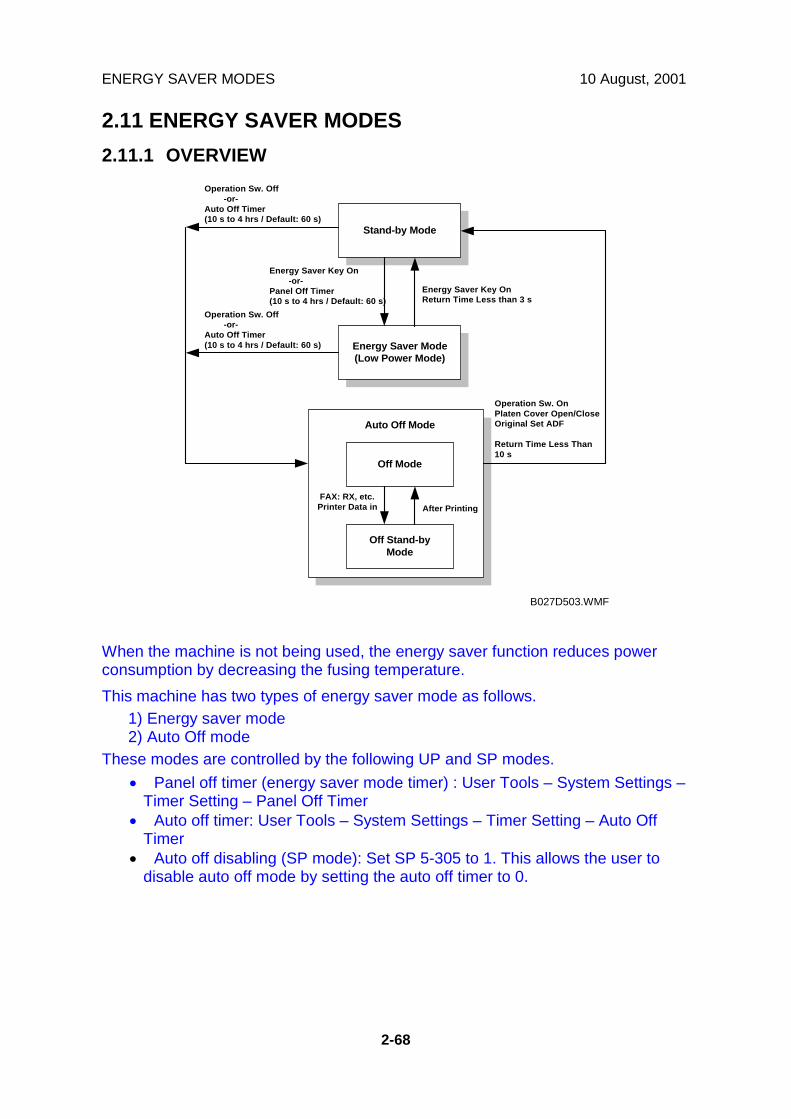
ENERGY SAVER MODES 10 August, 2001
2-68
2.11 ENERGY SAVER MODES2.11.1 OVERVIEW
When the machine is not being used, the energy saver function reduces powerconsumption by decreasing the fusing temperature.This machine has two types of energy saver mode as follows.
1) Energy saver mode2) Auto Off mode
These modes are controlled by the following UP and SP modes.• Panel off timer (energy saver mode timer) : User Tools – System Settings –
Timer Setting – Panel Off Timer• Auto off timer: User Tools – System Settings – Timer Setting – Auto Off
Timer• Auto off disabling (SP mode): Set SP 5-305 to 1. This allows the user to
disable auto off mode by setting the auto off timer to 0.
Stand-by Mode
Energy Saver Mode(Low Power Mode)
Auto Off Mode
Off Stand-byMode
Off Mode
FAX: RX, etc.Printer Data in After Printing
Energy Saver Key OnReturn Time Less than 3 s
Operation Sw. Off -or-Auto Off Timer(10 s to 4 hrs / Default: 60 s)
Operation Sw. OnPlaten Cover Open/CloseOriginal Set ADF
Return Time Less Than10 s
Operation Sw. Off -or-Auto Off Timer(10 s to 4 hrs / Default: 60 s)
Energy Saver Key On -or-Panel Off Timer(10 s to 4 hrs / Default: 60 s)
B027D503.WMF

10 August, 2001 ENERGY SAVER MODES
2-69
Det
aile
dD
escr
iptio
ns
2.11.2 ENERGY SAVER MODE
Entering the energy saver modeThe operation manual uses the term ‘panel off mode’ for the timer.The machine enters energy saver mode when one of the following is done.• The panel off timer runs out• The Clear Mode/Energy Saver Key is held down for one secondNote that the default setting of the panel off timer is 60 s, which is the same as theauto off timer. In this condition, if the machine is not touched for 60 s, it will gostraight to auto off mode. If the user wants an energy saver mode and an auto offmode, the panel off timer must be set to a shorter value than the auto off timer,What happens in energy saver modeWhen the machine enters energy saver mode, the fusing lamp drops to a certaintemperature, and the operation panel indicators are turned off except for theEnergy Saver LED and the Power LED.If the CPU receives an image print out command from an application (e. g. to printincoming fax data or to print data from a PC), the fusing temperature rises to printthe data.
Return to stand-by modeIf one of the following is done, the machine returns to stand-by mode:• The Clear Mode/Energy Saver Mode key is pressed• Any key on the operation panel or touch panel screen is pressed• An original is placed in the ADF• The ADF is lifted• A sheet of paper is placed in the by-pass feed tableThe recovery time from energy saver mode is about 3 s.
Mode OperationSwitch
EnergySaver LED Fusing Temp. +24V System +5V
EnergySaver On On 150oC On On

ENERGY SAVER MODES 10 August, 2001
2-70
2.11.3 AUTO OFF MODE
There are two Auto Off modes: Off Stand-by mode and Off mode. The differencebetween Off Stand-by mode and Off mode is the machine’s condition when itenters Auto Off mode.Entering off stand-by and off modesThe machine enters the Off Stand-by mode or Off mode when one of the followingis done.• The auto off timer runs out• The operation switch is pressed to turn the power offIf one or more of the following conditions exists, the machine enters Off Stand-bymode. If none of these conditions exist, the machine enters Off Mode.• Error or SC condition• An optional G4 unit is installed• Image data is stored in the memory• During memory TX or polling RX• The handset is off hook• An original is in the ADF• The ADF is openOff Stand-by modeThe system +5V is still supplied to all components. When the machine detects aringing signal or receives a stream of data for a print job, the +24V supply isactivated and the machine automatically prints the incoming message or executesthe print job.Off ModeThe system +5V supply also turns off. However, +5VE (+5V for energy savermode) is still activated. When the machine detects a ringing signal, off-hook signal,or receives a print job, the machine returns to the Off Stand-by mode and thesystem +5V and +24V supplies are activated.Returning to stand-by modeThe machine returns to stand-by mode when the operation switch is pressed. Therecovery time is about 10 s.
Mode OperationSwitch
EnergySaverMode
Fusing Lamp +24V System+5V Note
Off Stand-by Off Off Off(On when printing) On On
Off Off Off Off Off Off +5VE issupplied

10 August, 2001 INSTALLATION REQUIREMENTS
3-1
3. INSTALLATION PROCEDURE3.1 INSTALLATION REQUIREMENTS3.1.1 ENVIRONMENT
1. Temperature Range: 10°C to 32°C (50°F to 89.6°F)
2. Humidity Range: 15% to 80% RH
3. Ambient Illumination: Less than 1,500 lux (do not expose to direct sunlight.)
4. Ventilation: Room air should turn over at least 30 m3/hr/person
5. Ambient Dust: Less than 0.10 mg/m3 (2.7 x 10 -6 oz/yd3)
6. Avoid an area which is exposed to sudden temperature changes. This includes:1) Areas directly exposed to cool air from an air conditioner.2) Areas directly exposed to heat from a heater.
7. Do not place the machine in an area where it will be exposed to corrosivegases.
8. Do not install the machine at any location over 2,000 m (6,500 ft.) above sealevel.
9. Place the copier on a strong and level base. (Inclination on any side should beno more than 5 mm.)
10. Do not place the machine where it may be subjected to strong vibrations.
3.1.2 MACHINE LEVEL
Front to back: Within 5 mm (0.2") of levelRight to left: With in 5 mm (0.2") of level
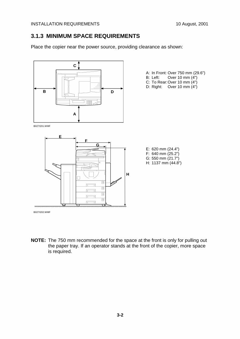
INSTALLATION REQUIREMENTS 10 August, 2001
3-2
3.1.3 MINIMUM SPACE REQUIREMENTS
Place the copier near the power source, providing clearance as shown:
NOTE: The 750 mm recommended for the space at the front is only for pulling outthe paper tray. If an operator stands at the front of the copier, more spaceis required.
B027I201.WMF
B027I202.WMF
C
A
B D
GF
E
A: In Front: Over 750 mm (29.6")B: Left: Over 10 mm (4")C: To Rear:Over 10 mm (4")D: Right: Over 10 mm (4")
E: 620 mm (24.4")F: 640 mm (25.2")G: 550 mm (21.7")H: 1137 mm (44.8")
H
10 August, 2001 INSTALLATION REQUIREMENTS
3-3
3.1.4 POWER REQUIREMENTS
!CAUTION1. Make sure that the wall outlet is near the copier and easily accessible.
Make sure the plug is firmly inserted in the outlet.2. Avoid multi-wiring.3. Be sure to ground the machine.
1. Input voltage level: 120 V, 60 Hz: More than 12 A220 V ~ 240 V, 50 Hz/60 Hz: More than 7 A110V, 50 Hz/60 Hz: More than 13 A
2. Permissible voltage fluctuation: ±10 %3. Do not set anything on the power cord.
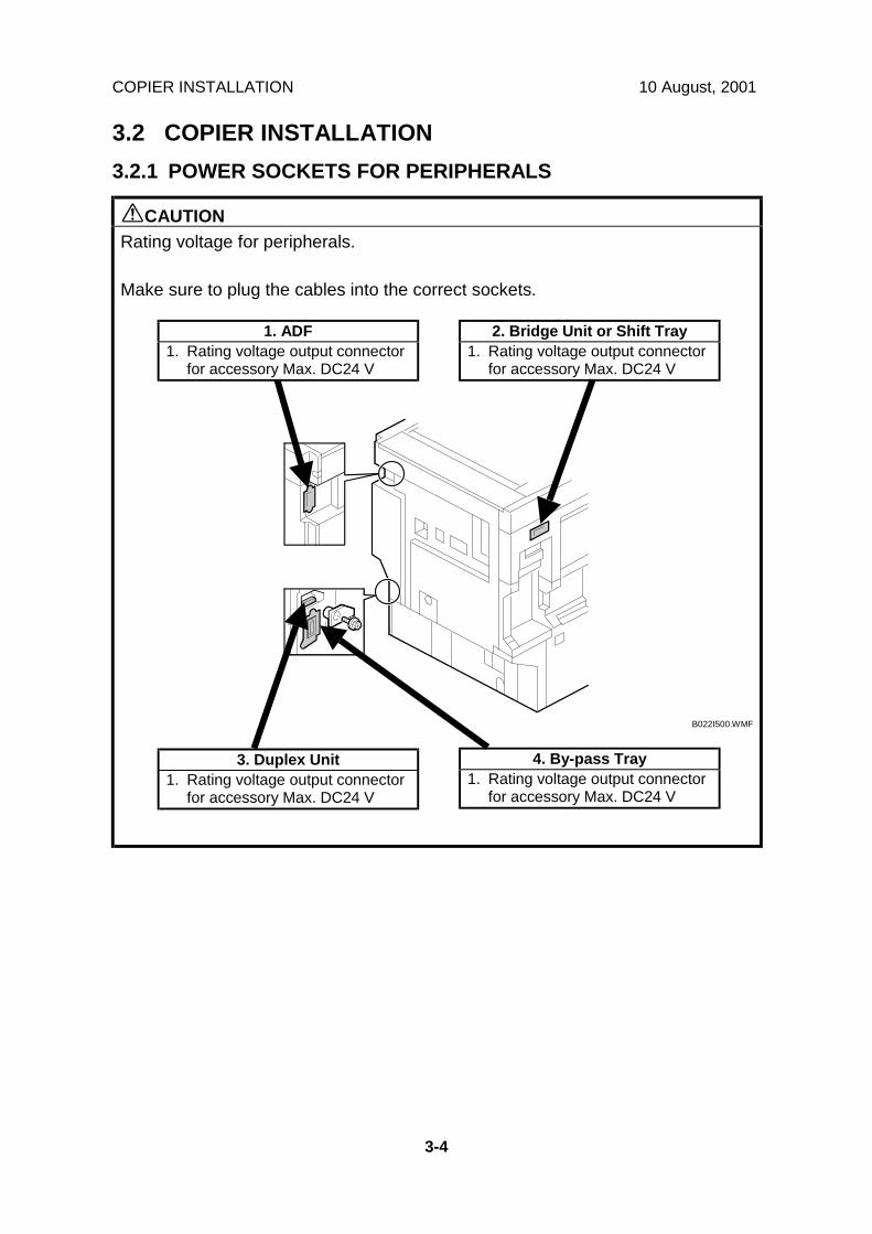
COPIER INSTALLATION 10 August, 2001
3-4
3.2 COPIER INSTALLATION3.2.1 POWER SOCKETS FOR PERIPHERALS
!CAUTIONRating voltage for peripherals.
Make sure to plug the cables into the correct sockets.
B022I500.WMF
1. ADF1. Rating voltage output connector
for accessory Max. DC24 V
2. Bridge Unit or Shift Tray1. Rating voltage output connector
for accessory Max. DC24 V
3. Duplex Unit1. Rating voltage output connector
for accessory Max. DC24 V
4. By-pass Tray1. Rating voltage output connector
for accessory Max. DC24 V

10 August, 2001 COPIER INSTALLATION
3-5
3.2.2 INSTALLATION FLOW CHART
The following flow chart shows how to install the optional units more efficiently.
Unpack the copier
Does the user require the Paper Tray Unit, LCT, or Finisher?
Place the copier on the Paper Tray Unit or LCTInstall the Paper Tray Unit or LCTInstall the copier
Does the user require the Memory Unit?
Install the Memory Unit
Does the user require the By-pass Tray?
Install the By-pass Tray
Does the user require the Shift Tray?
Install the Shift Tray
Does the user require the Finisher?
Install the Bridge Unit
Install the Finisher
Install the ARDF or Platen Cover (if required)
Yes No
Yes No
Yes No
Yes No
Yes No
Does the user require the Duplex Unit and/or 1-bin Tray Unit ?
Install the Interchange Unit
Install the Duplex Unit and/or 1-bin Tray Unit
Yes No
B022I513.WMF

COPIER INSTALLATION 10 August, 2001
3-6
3.2.3 ACCESSORY CHECK
Check the quantity and condition of the accessories in the box against the followinglist:
No. Description Q’ty1 Paper Tray Decal 12 Emblem 13 Model Name Decal 14 NECR 15 End Fence 16 HDD Caution Decal (-17, -57 only) 17 Operating Instructions – System Setting 18 Operating Instructions – Copy Reference 1

10 August, 2001 COPIER INSTALLATION
3-7
3.2.4 INSTALLATION PROCEDURE
!CAUTIONUnplug the machine power cord before starting the following procedure.
If the optional paper tray or the optional LCT is going to be installed now, put thecopier on the paper tray unit or the LCT first, then install these options, then installthe copier.NOTE: Keep the shipping retainers after installing the machine. They will be
reused if the machine is moved to another location in the future.1. Remove the tapes and the shipping retainer [A] on the exterior of the copier.2. Install the end fence [B].
B022I101.WMF
B022I502.WMF
B022I501.WMF
[A]
[B]

COPIER INSTALLATION 10 August, 2001
3-8
3. Open the front cover [A].4. Remove the red tag [B] and toner seal [C], then peel the sealing tape [D] off to
install the developer.5. Raise the toner bottle holder lever [E], push lever [F] down, and pull the toner
bottle holder [G] out.6. Shake the toner bottle [H] well.
NOTE: Do not remove the toner bottle cap [I] until after shaking.7. Unscrew the bottle cap [I] and insert the bottle into the holder.
NOTE: Do not touch the inner bottle cap [J].8. Reposition the holder and press down the holder lever to secure the bottle.
B022I102.WMF
B022I504.WMF
[A]
[B]
[C][D]
[F]
[E]
[G]
[H]
[I]
[J]
Ricoh Technical Services
RTB 12 Caution when opening toner bottles

10 August, 2001 COPIER INSTALLATION
3-9
9. Attach the appropriate emblem [A] to the front cover if the emblem is notattached to the front cover.
10. Pull the paper tray out and turn the paper size dial to select the appropriatesize. Adjust the side guides and end guide to match the paper size.NOTE: To move the side guides, first pull out the tray fully, then push down the
green lock at the rear of the tray.11. Attach the appropriate paper tray number decal [B] to the paper tray.
NOTE: Paper tray number decals are also used for the optional paper tray orthe optional LCT. Keep any remaining decals for use with theseoptional units.
B022I103.WMF
B022I503.WMF
[A]
[B]
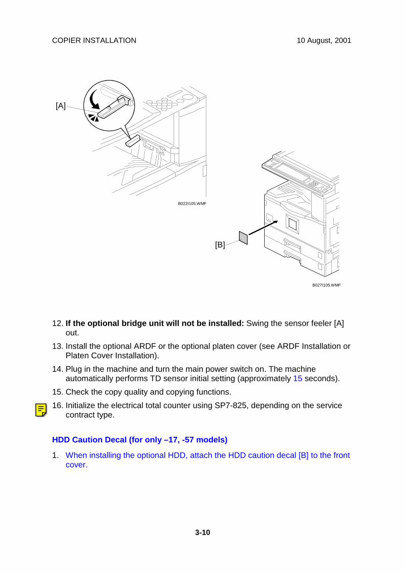
COPIER INSTALLATION 10 August, 2001
3-10
12. If the optional bridge unit will not be installed: Swing the sensor feeler [A]out.
13. Install the optional ARDF or the optional platen cover (see ARDF Installation orPlaten Cover Installation).
14. Plug in the machine and turn the main power switch on. The machineautomatically performs TD sensor initial setting (approximately 15 seconds).
15. Check the copy quality and copying functions.16. Initialize the electrical total counter using SP7-825, depending on the service
contract type.
HDD Caution Decal (for only –17, -57 models)
1. When installing the optional HDD, attach the HDD caution decal [B] to the frontcover.
B022I105.WMF
B027I105.WMF
[A]
[B]
Ricoh Technical Services
General RTB 13 Important notes concerning counter reset at installation

10 August, 2001 PAPER TRAY UNIT INSTALLATION
3-11
3.3 PAPER TRAY UNIT INSTALLATION3.3.1 ACCESSORY CHECK
Check the quantity and condition of the accessories against the following list.
No. Description Q’ty1 Securing Bracket 22 Screw – M4x10 4
3.3.2 INSTALLATION PROCEDURE
!CAUTIONUnplug the machine power cord before starting the following procedure.
1. Remove the strips of tape.2. Set the copier [A] on the paper tray unit [B].
NOTE: When installing the copier, be careful not to pinch the cable [C].
B390I601.WMF
B390I603.WMF
[A]
[B]
[C]
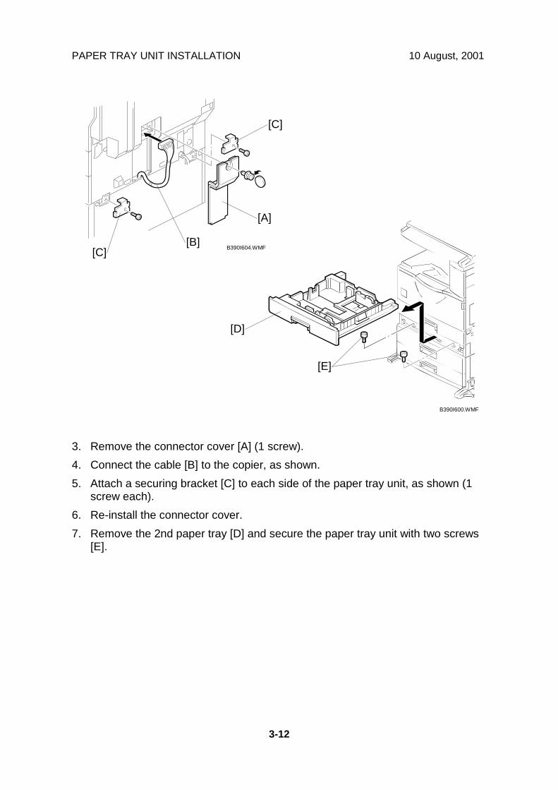
PAPER TRAY UNIT INSTALLATION 10 August, 2001
3-12
3. Remove the connector cover [A] (1 screw).4. Connect the cable [B] to the copier, as shown.5. Attach a securing bracket [C] to each side of the paper tray unit, as shown (1
screw each).6. Re-install the connector cover.7. Remove the 2nd paper tray [D] and secure the paper tray unit with two screws
[E].
B390I604.WMF
B390I600.WMF
[A]
[B][C]
[C]
[E]
[D]

10 August, 2001 PAPER TRAY UNIT INSTALLATION
3-13
8. Reinstall the 2nd paper tray and attach the appropriate paper tray numberdecal [A] to the paper tray.NOTE: The paper tray number decal is in the accessory box for the main
copier.9. Rotate the adjuster [B] until the machine cannot be pushed across the floor.10. Loads paper into the paper trays and select the proper paper size.11. Turn on the main switch.12. Check the machine’s operation and copy quality.
B390I602.WMF
B390I002.WMF
[A]
[B]

LCT INSTALLATION 10 August, 2001
3-14
3.4 LCT INSTALLATION3.4.1 ACCESSORY CHECK
Check the quantity and condition of the accessories against the following list.
No. Description Q’ty1 Securing Bracket 22 Screw – M4x10 43 Paper Size Decal 1
3.4.2 INSTALLATION PROCEDURE
!CAUTIONUnplug the machine power cord before starting the following procedure.
1. Remove the strips of tape.2. Set the copier [A] on the LCT [B].
NOTE: When installing the copier, be careful not to pinch the cable [C].
B391I505.WMF
B391I500.WMF
[A]
[B]
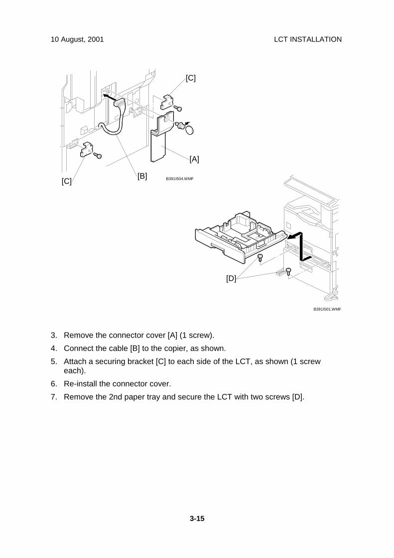
10 August, 2001 LCT INSTALLATION
3-15
3. Remove the connector cover [A] (1 screw).4. Connect the cable [B] to the copier, as shown.5. Attach a securing bracket [C] to each side of the LCT, as shown (1 screw
each).6. Re-install the connector cover.7. Remove the 2nd paper tray and secure the LCT with two screws [D].
B391I504.WMF
B391I501.WMF
[A]
[B][C]
[C]
[D]

LCT INSTALLATION 10 August, 2001
3-16
8. Load paper into the LCT.9. Reinstall the 2nd paper tray and attach the appropriate paper tray number
decal [A] and paper size decal [B] to the LCT.NOTE: The paper tray number decal is in the accessory box for the main
copier.10. Rotate the adjuster [C] until the machine cannot be pushed across the floor.11. Loads paper into the paper tray and turn on the main switch.12. Check the machine’s operation and copy quality.
B391I502.WMF
B391I506.WMF
[A]
[C]
[B]

10 August, 2001 AUTO REVERSE DOCUMENT FEEDER INSTALLATION
3-17
3.5 AUTO REVERSE DOCUMENT FEEDERINSTALLATION
3.5.1 ACCESSORY CHECK
Check the quantity and condition of the accessories against the following list.
No. Description Q’ty1 Scale Guide 12 DF Exposure Glass 13 Stud Screw 24 Knob Screw 25 Original Size Decal 26 Screwdriver Tool 1
3.5.2 INSTALLATION PROCEDURE
!CAUTIONUnplug the copier power cord before starting the following procedure.
1. Remove the strips of tape.
B386I500.WMF
B386I101.WMF
1
2
4
5
3 6

AUTO REVERSE DOCUMENT FEEDER INSTALLATION 10 August, 2001
3-18
2. Remove the left scale [A] (2 screws).3. Place the DF exposure glass [B] on the glass holder.
NOTE: When installing the DF exposure glass, make sure that the white point[C] is on the lower front side of the glass, as shown.
4. Peel off the backing [D] of the double-sided tape attached to the rear side of thescale guide [E], then install it (2 screws removed in step 2).
5. Install the two stud screws [F].6. Mount the DF on the copier, then slide the DF to the front as shown.7. Secure the DF unit with two screws [G].8. Connect the cable [H] to the copier.
B386I103.WMF
B386I104.WMF
[A][B]
[C] [D] [E]
[F]
[F]
[G]
[H]
[G]
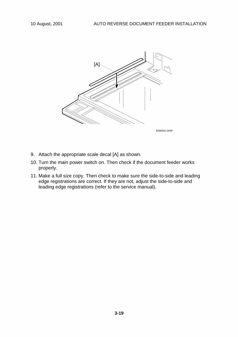
10 August, 2001 AUTO REVERSE DOCUMENT FEEDER INSTALLATION
3-19
9. Attach the appropriate scale decal [A] as shown.10. Turn the main power switch on. Then check if the document feeder works
properly.11. Make a full size copy. Then check to make sure the side-to-side and leading
edge registrations are correct. If they are not, adjust the side-to-side andleading edge registrations (refer to the service manual).
B386I501.WMF
[A]

INTERCHANGE UNIT INSTALLATION 10 August, 2001
3-20
3.6 INTERCHANGE UNIT INSTALLATION3.6.1 COMPONENT CHECK
Check the quantity and condition of the components against the following list.
No. Description Q’ty1 Interchange Unit 12 Connector Cover 13 Tapping Screw M3x8 1
B416I101.WMF
13
2

10 August, 2001 INTERCHANGE UNIT INSTALLATION
3-21
3.6.2 INSTALLATION PROCEDURE
!CAUTIONUnplug the copier power cord before starting the following procedure.
1. Remove all tapes.2. Open the right cover [A] of the copier.3. Open cover [B]4. Remove the metal clip [C].
NOTE: To remove the clip, push the small tab [D] on the clip into the slot [E],then the clip can be removed.
5. Remove the cover [B].
If the optional 1-bin tray unit (B413) will be installed, do steps 6 and 7.
6. Loosen the screw, push down tab [F] with a screwdriver, and remove the frontright cover [G].
7. Slide out the exit cover [H].
B416I502.WMF
B416I503.WMF
[G]
[H]
[C]
[B]
[D]
[F]
[A]
[E]

INTERCHANGE UNIT INSTALLATION 10 August, 2001
3-22
8. Open the cover [A] of the interchange unit.9. Install the interchange unit (2 connectors) [B].10. Secure the interchange unit with the knob screws [C].11. Attach the connector cover [D] (1 screw).
B416I104.WMF
B416I103.WMF
[D]
[A]
[B]
[C]

10 August, 2001 1-BIN TRAY UNIT INSTALLATION
3-23
3.7 1-BIN TRAY UNIT INSTALLATION3.7.1 COMPONENT CHECK
Check the quantity and condition of the components against the following list.
No. Description Q’ty1 1-Bin Tray Unit 12 Tray 13 Sub-Tray 14 Tray Guide 15 Paper Guide 16 Tapping Screw M3x8 1
3.7.2 INSTALLATION PROCEDURE
!CAUTIONUnplug the copier power cord before starting the following procedure.
NOTE: Before installing this 1-bin tray unit, the optional interchange unit (B416)must be installed.
1. Remove all tapes.2. If the optional bridge unit has been installed, open the right jam removal cover
[A] of the bridge unit.If the optional bridge unit is not installed, skip this step.
B413I101.WMF
B413I501.WMF
1
2
34
56
[A]

1-BIN TRAY UNIT INSTALLATION 10 August, 2001
3-24
3. If the front right cover [A] is installed, remove it.4. Install the 1-bin tray unit [B] (1 screw).5. Connect the connector [C].6. Reinstall the front right cover.7. Peel off the backing [D] of the double-sided tape attached to the paper guide
[E]. Then attach the paper guide to the underside of the scanner unit as shown.
B413I103.WMF
B413I500.WMF [D]
[E]
[B]
[C]
[A]

10 August, 2001 1-BIN TRAY UNIT INSTALLATION
3-25
12. Install the tray guide [A].13. Install the tray [B].14. Install the sub-tray [C].15. Turn on the main power switch and check the 1-bin tray unit operation.
B413I105.WMF
[A]
[B]
[C]
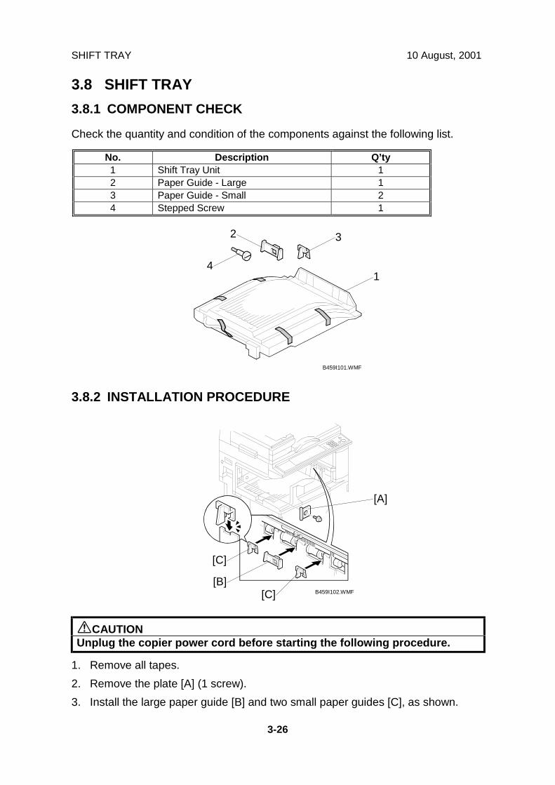
SHIFT TRAY 10 August, 2001
3-26
3.8 SHIFT TRAY3.8.1 COMPONENT CHECK
Check the quantity and condition of the components against the following list.
No. Description Q’ty1 Shift Tray Unit 12 Paper Guide - Large 13 Paper Guide - Small 24 Stepped Screw 1
3.8.2 INSTALLATION PROCEDURE
!CAUTIONUnplug the copier power cord before starting the following procedure.
1. Remove all tapes.2. Remove the plate [A] (1 screw).3. Install the large paper guide [B] and two small paper guides [C], as shown.
B459I101.WMF
B459I102.WMF
1
2 3
4
[A]
[B]
[C]
[C]
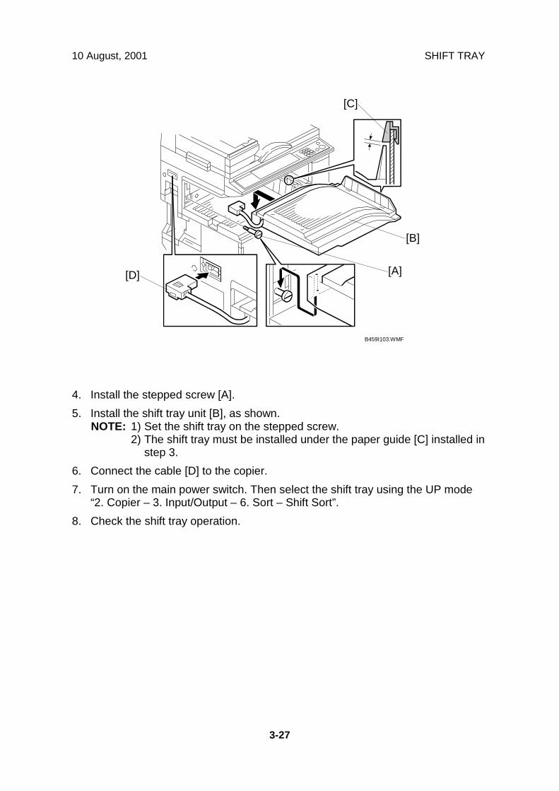
10 August, 2001 SHIFT TRAY
3-27
4. Install the stepped screw [A].5. Install the shift tray unit [B], as shown.
NOTE: 1) Set the shift tray on the stepped screw.2) The shift tray must be installed under the paper guide [C] installed in
step 3.6. Connect the cable [D] to the copier.7. Turn on the main power switch. Then select the shift tray using the UP mode
“2. Copier – 3. Input/Output – 6. Sort – Shift Sort”.8. Check the shift tray operation.
B459I103.WMF
[A]
[B]
[D]
[C]

BY-PASS FEED UNIT INSTALLATION 10 August, 2001
3-28
3.9 BY-PASS FEED UNIT INSTALLATION3.9.1 COMPONENTS CHECK
Check the quantity and condition of the components against the following list.
No. Description Q’ty1 By-pass Tray Unit 12 Unit Holder 13 Tapping Screw 24 Allen Key 1
3.9.2 INSTALLATION PROCEDURE
!CAUTIONUnplug the copier power cord before starting the following procedure.
1. Remove all tapes.2. Remove the entrance cover [A] (2 screws) and two screws [B].
B415I101.WMF
B415I500.WMF
1
2
3
4
[A]
[B]
[B]

10 August, 2001 BY-PASS FEED UNIT INSTALLATION
3-29
3. Install the unit holder [A] using the Allen key (4 set screws).NOTE: 1) Make sure that the four screws are tightened in the proper order, as
shown above. Otherwise, when the optional duplex unit (B414) isinstalled, it will not properly lock in place.
2) After securing the unit, store the Allen key in the inner cover [B] forfuture use.
4. If the optional duplex unit (B414) will be installed: Remove the indicatedparts [C] of the by-pass tray unit [D].
5. Install the by-pass tray unit (2 screws, 1 connector).6. Turn the main power switch on and check the by-pass tray function.7. Make a copy from the by-pass tray. Then check the registration.
B415I105.WMF B415I104.WMF
B415I502.WMFB415I501.WMF
[C][D]
[C]
[D]
[B]
[A]

DUPLEX UNIT INSTALLATION 10 August, 2001
3-30
3.10 DUPLEX UNIT INSTALLATION3.10.1 ACCESSORY CHECK
Check the quantity and condition of the accessories against the following list.
No. Description Q’ty1 Duplex Unit 12 Connector Cover 13 Bracket 14 Clip 15 Unit Holder 16 Unit Holder Cover 17 Allen Key 18 Tapping Screw - M3x8 4
B414I101.WMF
B414I102.WMF
23
4
7
8
15
6
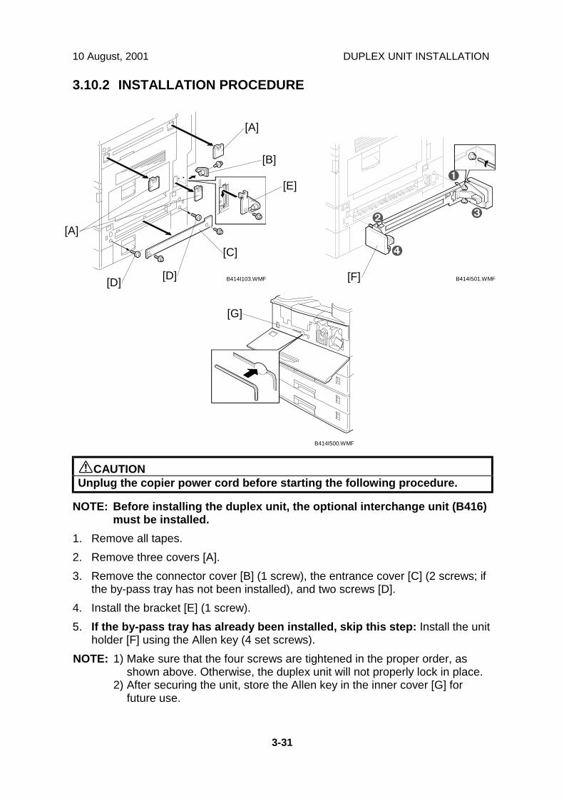
10 August, 2001 DUPLEX UNIT INSTALLATION
3-31
3.10.2 INSTALLATION PROCEDURE
!CAUTIONUnplug the copier power cord before starting the following procedure.
NOTE: Before installing the duplex unit, the optional interchange unit (B416)must be installed.
1. Remove all tapes.2. Remove three covers [A].3. Remove the connector cover [B] (1 screw), the entrance cover [C] (2 screws; if
the by-pass tray has not been installed), and two screws [D].4. Install the bracket [E] (1 screw).5. If the by-pass tray has already been installed, skip this step: Install the unit
holder [F] using the Allen key (4 set screws).NOTE: 1) Make sure that the four screws are tightened in the proper order, as
shown above. Otherwise, the duplex unit will not properly lock in place.2) After securing the unit, store the Allen key in the inner cover [G] for
future use.
B414I103.WMF B414I501.WMF
B414I500.WMF
[A]
[B]
[C]
[E]
[A]
[D] [F][D]
[G]
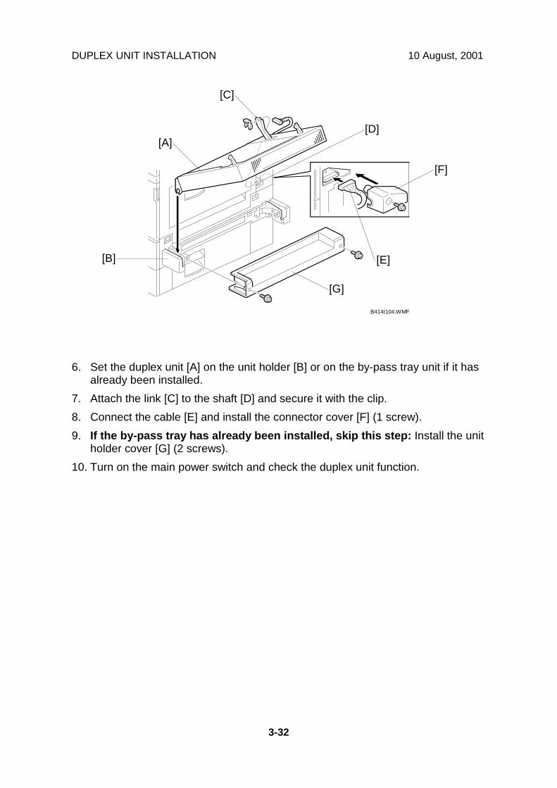
DUPLEX UNIT INSTALLATION 10 August, 2001
3-32
6. Set the duplex unit [A] on the unit holder [B] or on the by-pass tray unit if it hasalready been installed.
7. Attach the link [C] to the shaft [D] and secure it with the clip.8. Connect the cable [E] and install the connector cover [F] (1 screw).9. If the by-pass tray has already been installed, skip this step: Install the unit
holder cover [G] (2 screws).10. Turn on the main power switch and check the duplex unit function.
B414I104.WMF
[A]
[B]
[C]
[D]
[E]
[F]
[G]

10 August, 2001 BRIDGE UNIT INSTALLATION
3-33
3.11 BRIDGE UNIT INSTALLATION3.11.1 ACCESSORY CHECK
Check the quantity and condition of the accessories against the following list.
No. Description Q’ty1 Bridge Unit 12 Securing Plate 13 Shoulder Screw 14 Knob Screw 1
3.11.2 INSTALLATION PROCEDURE
- For A265 and A267 copiers -
!CAUTIONUnplug the copier power cord before starting the following procedure.
1. Remove all tapes.2. Loosen the screw [A] and remove the front right cover [B].3. If the sensor feeler [C] is out, fold it away into the machine.
B417I101.WMF
B417I500.WMFB417I501.WMF
1
2
3
4
[C]
[B]
[A]

BRIDGE UNIT INSTALLATION 10 August, 2001
3-34
4. Remove the cover [A] (1 screw).5. Install the bridge unit [B] (1 shoulder screw, 1 knob screw).6. Reinstall the front right cover [C].7. Connect the cable [D] to the main machine.8. Attach the securing plate [E], as shown.
NOTE: Do not attach it with a screw; this is done when securing the front standfor the optional finisher.
9. Install the optional finisher (refer to the finisher installation procedure).
B417I102.WMF
B417I103.WMF
[A]
[B][D]
[C]
[E]
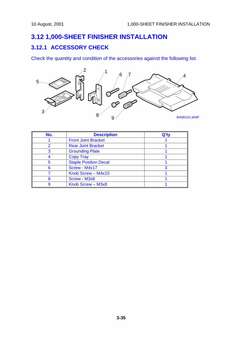
10 August, 2001 1,000-SHEET FINISHER INSTALLATION
3-35
3.12 1,000-SHEET FINISHER INSTALLATION3.12.1 ACCESSORY CHECK
Check the quantity and condition of the accessories against the following list.
No. Description Q’ty1 Front Joint Bracket 12 Rear Joint Bracket 13 Grounding Plate 14 Copy Tray 15 Staple Position Decal 16 Screw - M4x17 37 Knob Screw – M4x10 18 Screw - M3x8 19 Knob Screw – M3x8 1
B408I101.WMF
12
3
45
6 7
8 9
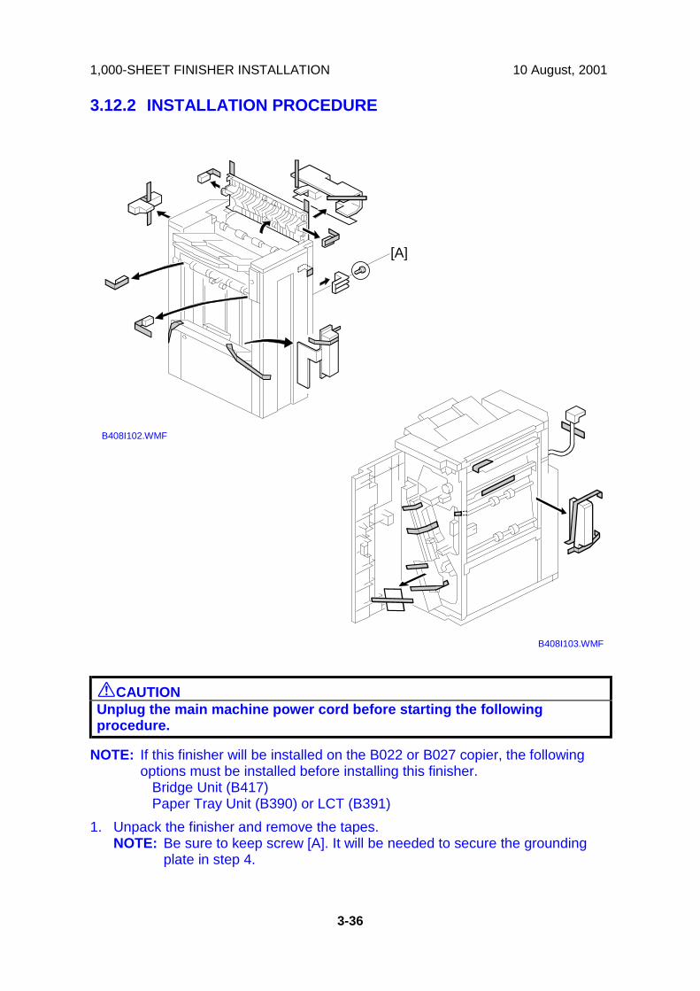
1,000-SHEET FINISHER INSTALLATION 10 August, 2001
3-36
3.12.2 INSTALLATION PROCEDURE
!CAUTIONUnplug the main machine power cord before starting the followingprocedure.
NOTE: If this finisher will be installed on the B022 or B027 copier, the followingoptions must be installed before installing this finisher. Bridge Unit (B417) Paper Tray Unit (B390) or LCT (B391)
1. Unpack the finisher and remove the tapes.NOTE: Be sure to keep screw [A]. It will be needed to secure the grounding
plate in step 4.
B408I103.WMF
B408I102.WMF
[A]
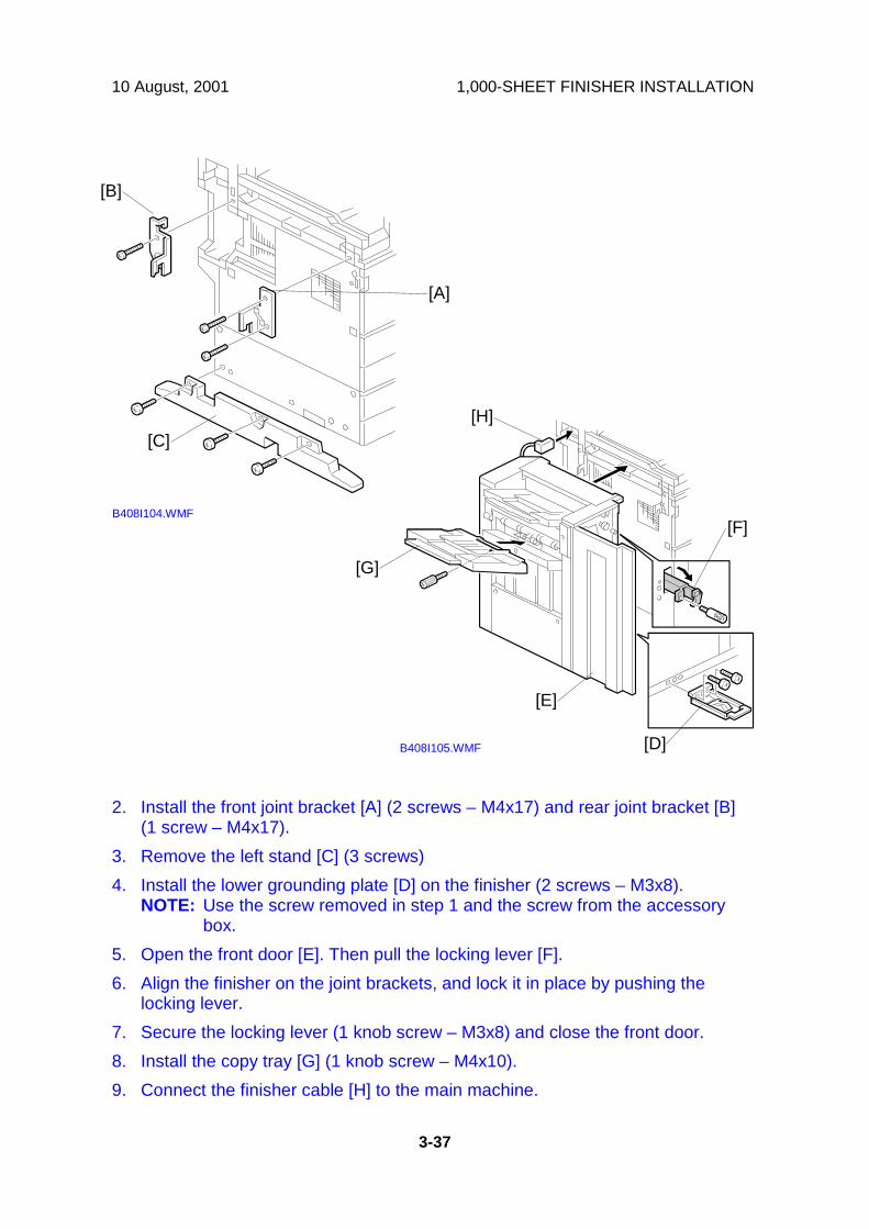
10 August, 2001 1,000-SHEET FINISHER INSTALLATION
3-37
2. Install the front joint bracket [A] (2 screws – M4x17) and rear joint bracket [B](1 screw – M4x17).
3. Remove the left stand [C] (3 screws)4. Install the lower grounding plate [D] on the finisher (2 screws – M3x8).
NOTE: Use the screw removed in step 1 and the screw from the accessorybox.
5. Open the front door [E]. Then pull the locking lever [F].6. Align the finisher on the joint brackets, and lock it in place by pushing the
locking lever.7. Secure the locking lever (1 knob screw – M3x8) and close the front door.8. Install the copy tray [G] (1 knob screw – M4x10).9. Connect the finisher cable [H] to the main machine.
B408I104.WMF
B408I105.WMF
[A]
[B]
[C]
[E]
[F]
[G]
[H]
[D]

1,000-SHEET FINISHER INSTALLATION 10 August, 2001
3-38
10. Attach the staple position decal [A] to the ARDF as shown.11. Turn on the ac switch and check the finisher operation.
B408I501.WMF
[A]

10 August, 2001 500-SHEET FINISHER INSTALLATION
3-39
3.13 500-SHEET FINISHER INSTALLATION3.13.1 ACCESSORY CHECK
Check the quantity and condition of the accessories against the following list.
No. Description Q’ty1 Unit Holder 12 Entrance Guide 13 Output Tray 14 Snap Ring 25 Knob Screw 2
B442I101.WMF
1
2
3
4 5
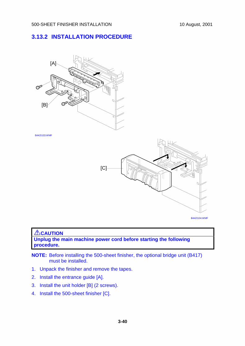
500-SHEET FINISHER INSTALLATION 10 August, 2001
3-40
3.13.2 INSTALLATION PROCEDURE
!CAUTIONUnplug the main machine power cord before starting the followingprocedure.
NOTE: Before installing the 500-sheet finisher, the optional bridge unit (B417)must be installed.
1. Unpack the finisher and remove the tapes.2. Install the entrance guide [A].3. Install the unit holder [B] (2 screws).4. Install the 500-sheet finisher [C].
B442I103.WMF
B442I104.WMF
[A]
[B]
[C]

10 August, 2001 500-SHEET FINISHER INSTALLATION
3-41
5. Install the output tray [A] as shown (2 snap rings).6. Connect the finisher cable [B].7. Turn on the main power switch and check the finisher operation.
B442I105.WMF
[A]
[B]
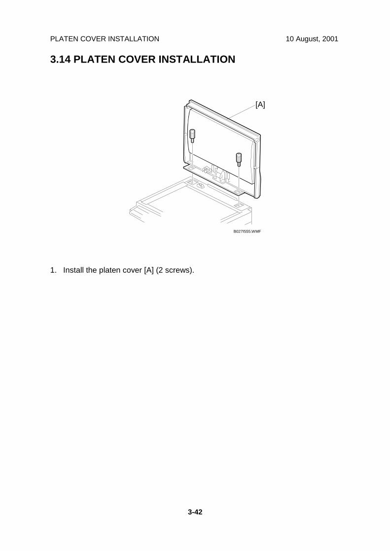
PLATEN COVER INSTALLATION 10 August, 2001
3-42
3.14 PLATEN COVER INSTALLATION
1. Install the platen cover [A] (2 screws).
B027I555.WMF
[A]

10 August, 2001 PLATEN COVER INSTALLATION
3-43
3.14.1 MEMORY (G578/G579)
!CAUTIONUnplug the main machine power cord before starting the followingprocedure.
1. Remove the connector cover [A] and rear cover [B] (4 screws).2. Remove the shield cover [C] (7 screws).3. Install the memory DIMM [D] on the controller board.4. Replace the controller board cover and rear cover.
B453I101.WMF
B453I109.WMF
B453I503.WMF
[A]
[B]
[C]
[D]

PLATEN COVER INSTALLATION 10 August, 2001
3-44
3.14.2 HDD (B420)
!CAUTIONUnplug the main machine power cord before starting the followingprocedure.
1. Attach the HDD [A] to the HDD bracket [B] (4 stepped screws).NOTE: The PCB side of the HDD must face the HDD bracket.
2. Attach the shield plate [C] to the HDD (4 – M3x3 screws).3. Connect the cable [D] to the HDD.
NOTE: The marked location [E] which is not a pinhole must face the HDD.4. Remove the connector cover [F] and rear cover [G] (4 screws).
B453I102.WMF
B453I103.WMF
B453I101.WMF
[A]
[B]
[C][D]
[E]
[F]
[G]
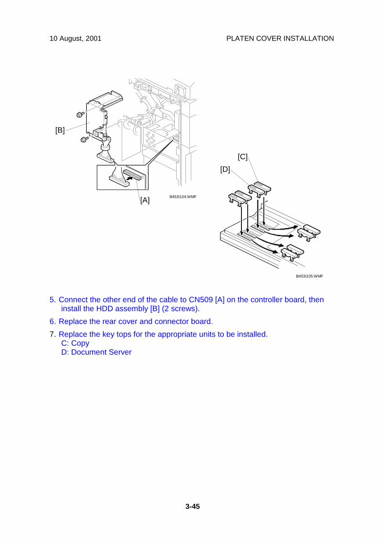
10 August, 2001 PLATEN COVER INSTALLATION
3-45
5. Connect the other end of the cable to CN509 [A] on the controller board, theninstall the HDD assembly [B] (2 screws).
6. Replace the rear cover and connector board.7. Replace the key tops for the appropriate units to be installed.
C: CopyD: Document Server
B453I104.WMF
B453I105.WMF
[A]
[B]
[C][D]

KEY COUNTER INSTALLATION 10 August, 2001
3-46
3.15 KEY COUNTER INSTALLATION
!CAUTIONUnplug the machine power cord before starting the following procedure.
1. Remove two caps [A].2. Connect the key counter cable [B].3. Install the stepped screw [C].4. Hold the key counter plate nuts [D] on the inside of the key counter bracket [E]
and insert the key counter holder [F].5. Secure the key counter holder to the bracket (2 screws).6. Install the key counter cover [G] (2 screws).
B027I231.WMF
B027I500.WMF
[A]
[B]
[C]
[D]
[E]
[F]
[G]

10 August, 2001 KEY COUNTER INSTALLATION
3-47
7. Connect the cable [A].8. Hook the key counter holder assembly [B] onto the stepped screw [C].9. Secure the key counter holder assembly with a screw [D].10. Set SP5-401-2 to 1 (This enables the restricted access control function.)
NOTE: The key counter function is made available for other modes bychanging the following SP modes.• SP5-401-12 (Document server mode)• SP5-401-22 (Fax mode)• SP5-401-32 (Scanner mode)• SP5-401-42 (Printer mode)
B027I232.WMF
[A]
[C]
[D]
[B]
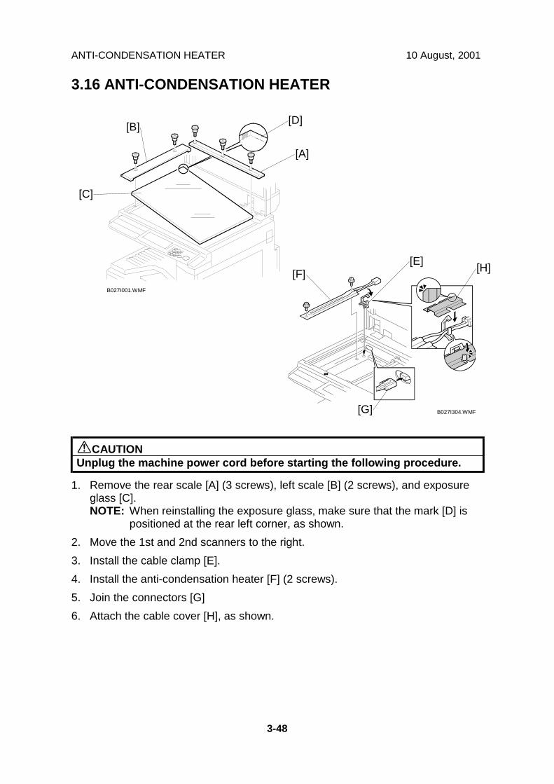
ANTI-CONDENSATION HEATER 10 August, 2001
3-48
3.16 ANTI-CONDENSATION HEATER
!CAUTIONUnplug the machine power cord before starting the following procedure.
1. Remove the rear scale [A] (3 screws), left scale [B] (2 screws), and exposureglass [C].NOTE: When reinstalling the exposure glass, make sure that the mark [D] is
positioned at the rear left corner, as shown.2. Move the 1st and 2nd scanners to the right.3. Install the cable clamp [E].4. Install the anti-condensation heater [F] (2 screws).5. Join the connectors [G]6. Attach the cable cover [H], as shown.
B027I001.WMF
B027I304.WMF
[A]
[B]
[C]
[D]
[E][F]
[G]
[H]

10 August, 2001 TRAY HEATER
3-49
3.17 TRAY HEATER
!CAUTIONUnplug the machine power cord before starting the following procedure.
1. Remove the connector cover [A] and rear cover [B] (4 screws).2. Slide out the 1st and 2nd paper trays.3. Pass the connector [C] through the opening [D].4. Install the tray heater assembly [E] (1 screw).
B027I510.WMF
B027I502.WMF
[A]
[B]
[C]
[D]
[E]

TRAY HEATER 10 August, 2001
3-50
5. Remove the 2nd paper lift motor [A] (2 screws, 1 connector).6. Route the heater cable [B] to the side of rivet [C] and under bracket [D].7. Clamp the heater cable [B] as shown.8. Joint the heater cable and the ac cable [E].9. Reinstall the paper lift motor [A] and reassemble the machine.
B027I513.WMF
B027I501.WMF
[A]
[B]
[E]
[B]
[C][D]

10 August, 2001 TRAY HEATER (OPTIONAL PAPER TRAY UNIT)
3-51
3.18 TRAY HEATER (OPTIONAL PAPER TRAY UNIT)
!CAUTIONUnplug the machine power cord before starting the following procedure.
1. Remove the joint brackets [A] (1 screw each).2. Remove the rear cover [B] for the optional paper tray unit (2 screws).3. Remove the cable guide [C] (1 screw).4. Install the clamps [D].
B027I506.WMF
B027I509.WMF
[A]
[B]
[A]
[C]
[D]
[D]

TRAY HEATER (OPTIONAL PAPER TRAY UNIT) 10 August, 2001
3-52
5. Slide out the two paper trays from the optional paper tray unit.6. Pass the connector [A] through the opening [B].7. Install the tray heater assembly [C] (1 screw).8. Clamp the cables [D], as shown.9. Join the connectors [E].10. Reinstall the cable guide.
B027I503.WMF
B027I505.WMF
[A][B]
[C]
[D]
[E][D]
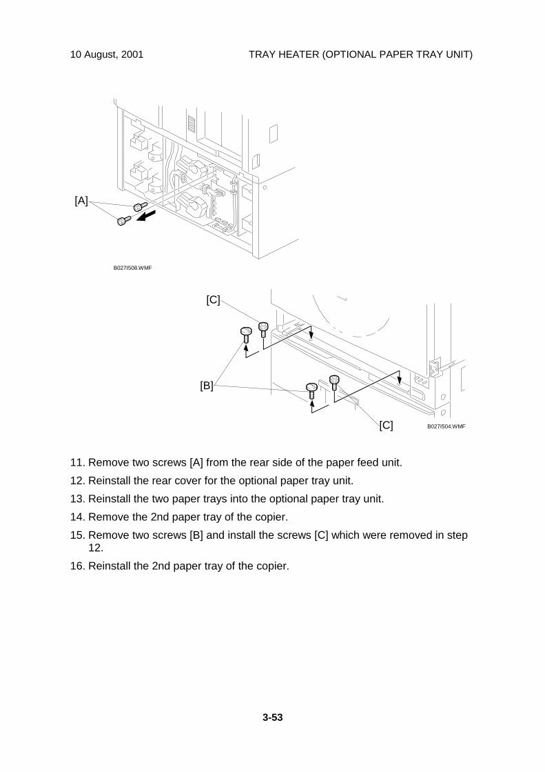
10 August, 2001 TRAY HEATER (OPTIONAL PAPER TRAY UNIT)
3-53
11. Remove two screws [A] from the rear side of the paper feed unit.12. Reinstall the rear cover for the optional paper tray unit.13. Reinstall the two paper trays into the optional paper tray unit.14. Remove the 2nd paper tray of the copier.15. Remove two screws [B] and install the screws [C] which were removed in step
12.16. Reinstall the 2nd paper tray of the copier.
B027I508.WMF
B027I504.WMF
[A]
[B]
[C]
[C]
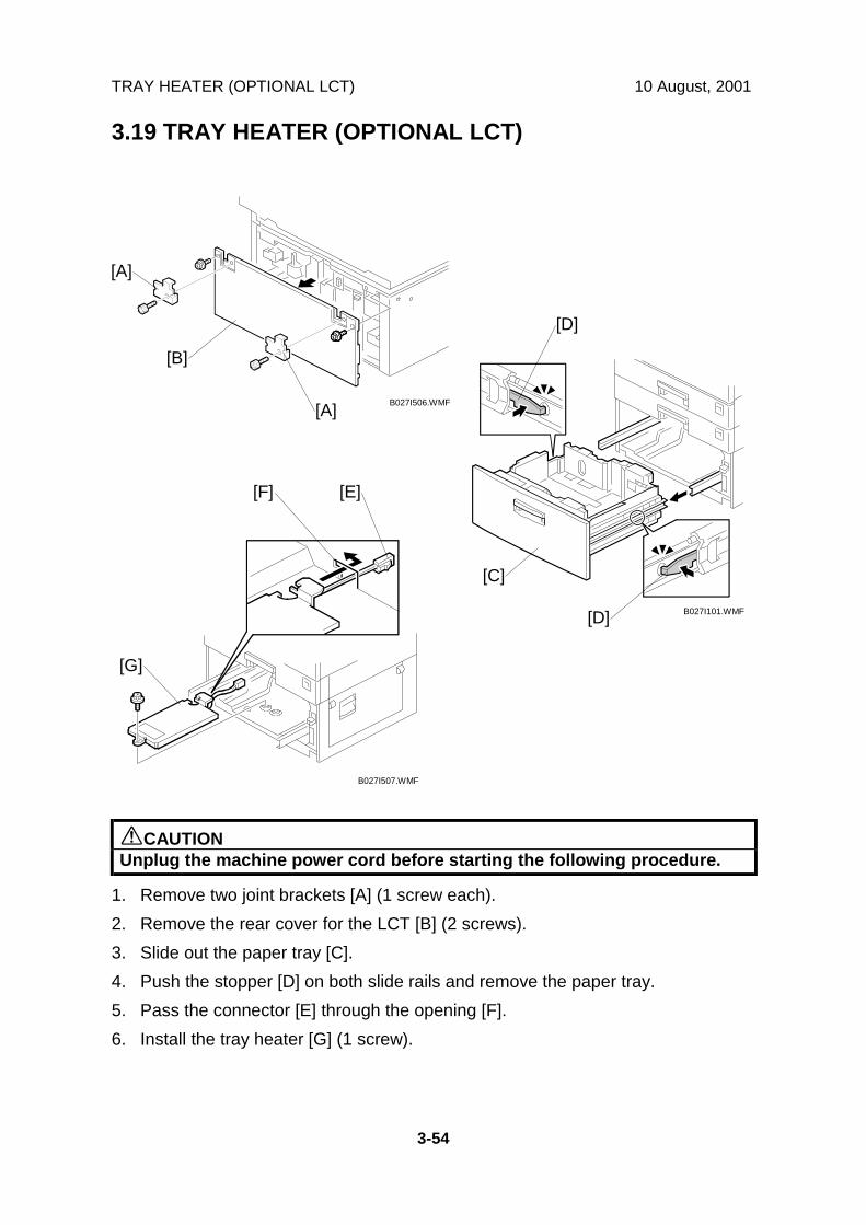
TRAY HEATER (OPTIONAL LCT) 10 August, 2001
3-54
3.19 TRAY HEATER (OPTIONAL LCT)
!CAUTIONUnplug the machine power cord before starting the following procedure.
1. Remove two joint brackets [A] (1 screw each).2. Remove the rear cover for the LCT [B] (2 screws).3. Slide out the paper tray [C].4. Push the stopper [D] on both slide rails and remove the paper tray.5. Pass the connector [E] through the opening [F].6. Install the tray heater [G] (1 screw).
B027I506.WMF
B027I101.WMF
B027I507.WMF
[A]
[B]
[A]
[C]
[D]
[D]
[E][F]
[G]
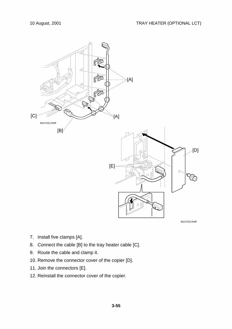
10 August, 2001 TRAY HEATER (OPTIONAL LCT)
3-55
7. Install five clamps [A].8. Connect the cable [B] to the tray heater cable [C].9. Route the cable and clamp it.10. Remove the connector cover of the copier [D].11. Join the connectors [E].12. Reinstall the connector cover of the copier.
B027I252.WMF
B027I253.WMF
[A]
[B]
[C] [A]
[D]
[E]
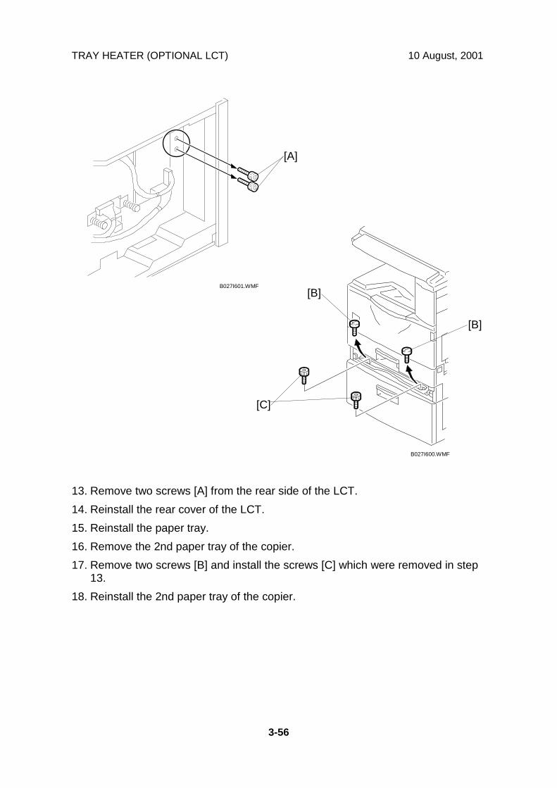
TRAY HEATER (OPTIONAL LCT) 10 August, 2001
3-56
13. Remove two screws [A] from the rear side of the LCT.14. Reinstall the rear cover of the LCT.15. Reinstall the paper tray.16. Remove the 2nd paper tray of the copier.17. Remove two screws [B] and install the screws [C] which were removed in step
13.18. Reinstall the 2nd paper tray of the copier.
B027I601.WMF
B027I600.WMF
[A]
[B]
[C]
[B]

10 August, 2001 GENERAL CAUTION
4-1
Serv
ice
Tabl
es
4. SERVICE TABLES4.1 GENERAL CAUTION
!CAUTIONNever turn off the main power switch when the power LED is lit or flashing.To avoid damaging the hard disk or memory, press the operation powerswitch to switch the power off, wait for the power LED to go off, and thenswitch the main power switch off.
NOTE: The main power LED ( ) lights or flashes while the platen cover orARDF is open, while the main machine is communicating with a faxmachine or the network server, or while the machine is accessing the harddisk or memory for reading or writing data.
Do not turn off the main switch while any of the electrical components are active.Doing so might cause damage to units, such as the PCU, when they are pulled outof or put back into the copier.
4.1.1 PCU (PHOTOCONDUCTOR UNIT)The PCU consists of the OPC drum, development unit, charge roller, and cleaningunit. Follow the cautions below when handling a PCU.
1. Never touch the drum surface with bare hands. When the drum surface istouched or becomes dirty, wipe it with a dry cloth or clean it with wet cotton.Wipe with a dry cloth after cleaning with the cotton.
2. Never used alcohol to clean the drum; alcohol dissolves the drum surface.3. Store the PCU in a cool, dry place away from heat.4. Never expose the drum to corrosive gases such as ammonia gas.5. Never shake the used PCU. Doing so may cause toner and/or developer to spill
out.6. Dispose of used PCUs in accordance with local regulations.
4.1.2 TRANSFER ROLLER UNIT1. Never touch the transfer roller surface with bare hands.2. Take care not to scratch the transfer roller as the surface is easily damaged.
4.1.3 SCANNER UNIT1. Clean the exposure glass with alcohol or with glass cleaner to reduce the
amount of static electricity on the surface of the glass.2. Use a blower brush or a cotton pad with water to clean the mirrors and lens.

GENERAL CAUTION 10 August, 2001
4-2
3. Do not bend or crease the exposure lamp flat cable.4. Do not disassemble the lens unit. Doing so will throw the lens and the copy
image out of focus.5. Do not turn any of the CCD positioning screws. Doing so will throw the CCD out
of position.
4.1.4 LASER UNIT1. Do not loosen the screws that secure the LD drive board to the laser diode
casing. Doing so will throw the LD unit out of adjustment.2. Do not adjust the variable resistors on the LD unit, as they are adjusted in the
factory.3. The polygon mirror and F-theta mirror are very sensitive to dust.4. Do not touch the glass surface of the polygon mirror motor unit with bare
hands.
4.1.5 FUSING UNIT1. After installing the fusing thermistor, make sure that it is in contact with the hot
roller and that the hot roller can rotate freely.2. Be careful not to damage the edges of the hot roller strippers or their tension
springs.3. Do not touch the fusing lamp and rollers with bare hands.4. Make sure that the fusing lamp is positioned correctly and that it does not touch
the inner surface of the hot roller.
4.1.6 PAPER FEED1. Do not touch the surface of the paper feed roller.2. To avoid paper misfeeds, the side fences and end fences of the paper tray
must be positioned correctly to align with the actual paper size.
4.1.7 OTHERS1. The TD sensor initial setting is performed automatically after installing the new
PCU and closing the front cover. Never open the front cover or turn off the mainswitch during this time. The main motor stops when the initial setting hasfinished.
2. The toner bottle should be replaced while the main switch is on.3. If the optional tray, drum, and optics anti-condensation heaters have been
installed, keep the copier power cord plugged in, even when the copier mainswitch is turned off. This keeps the heaters energized.

10 August, 2001 SERVICE PROGRAM MODE
4-3
Serv
ice
Tabl
es
4.2 SERVICE PROGRAM MODE4.2.1 SERVICE PROGRAM MODE OPERATION
The service program mode is used to check electrical data, change modes, andadjust values. Two service program modes are provided:• SP Mode (Service). Includes all the options in the SP displays for normal
maintenance and adjustments.• SSP Mode (Special Service). Includes the normal SP modes and some
additional options in the SP displays not required for normal settings andadjustments. (Most are marked “DFU” in the following tables.) Do not changethese important settings needlessly. For details, contact your supervisor.
Entering and Exiting SP mode" 1. Press the Clear Mode key.#$% 2. Use the keypad to enter “107”.& 3. Hold down Clear/Stop for at least 3 seconds.
4. Enter the Service Mode.To enter the Normal Service Mode:
Copy SP On the touch-panel, press Copy SP.To enter the Special Service Mode:
' Copy SP Hold down ' and then press Copy SP.Exit 5. Press Exit twice to return to the copy window.
NOTE: Use SP2-902 to perform test pattern printing. (☛ 4.2.3)
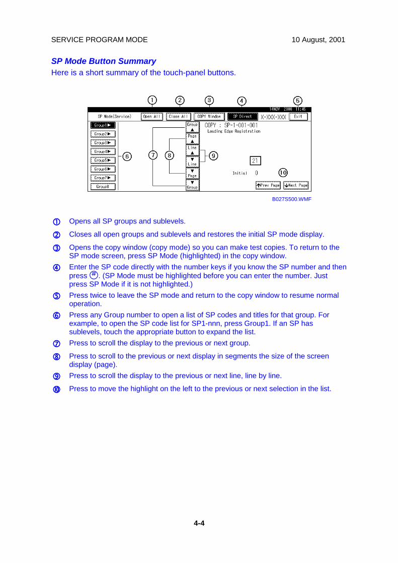
SERVICE PROGRAM MODE 10 August, 2001
4-4
SP Mode Button SummaryHere is a short summary of the touch-panel buttons.
!!!! Opens all SP groups and sublevels.
"""" Closes all open groups and sublevels and restores the initial SP mode display.
#### Opens the copy window (copy mode) so you can make test copies. To return to theSP mode screen, press SP Mode (highlighted) in the copy window.
$$$$ Enter the SP code directly with the number keys if you know the SP number and thenpress '. (SP Mode must be highlighted before you can enter the number. Justpress SP Mode if it is not highlighted.)
%%%% Press twice to leave the SP mode and return to the copy window to resume normaloperation.
&&&& Press any Group number to open a list of SP codes and titles for that group. Forexample, to open the SP code list for SP1-nnn, press Group1. If an SP hassublevels, touch the appropriate button to expand the list.
'''' Press to scroll the display to the previous or next group.
(((( Press to scroll to the previous or next display in segments the size of the screendisplay (page).
)))) Press to scroll the display to the previous or next line, line by line.
**** Press to move the highlight on the left to the previous or next selection in the list.
B027S500.WMF
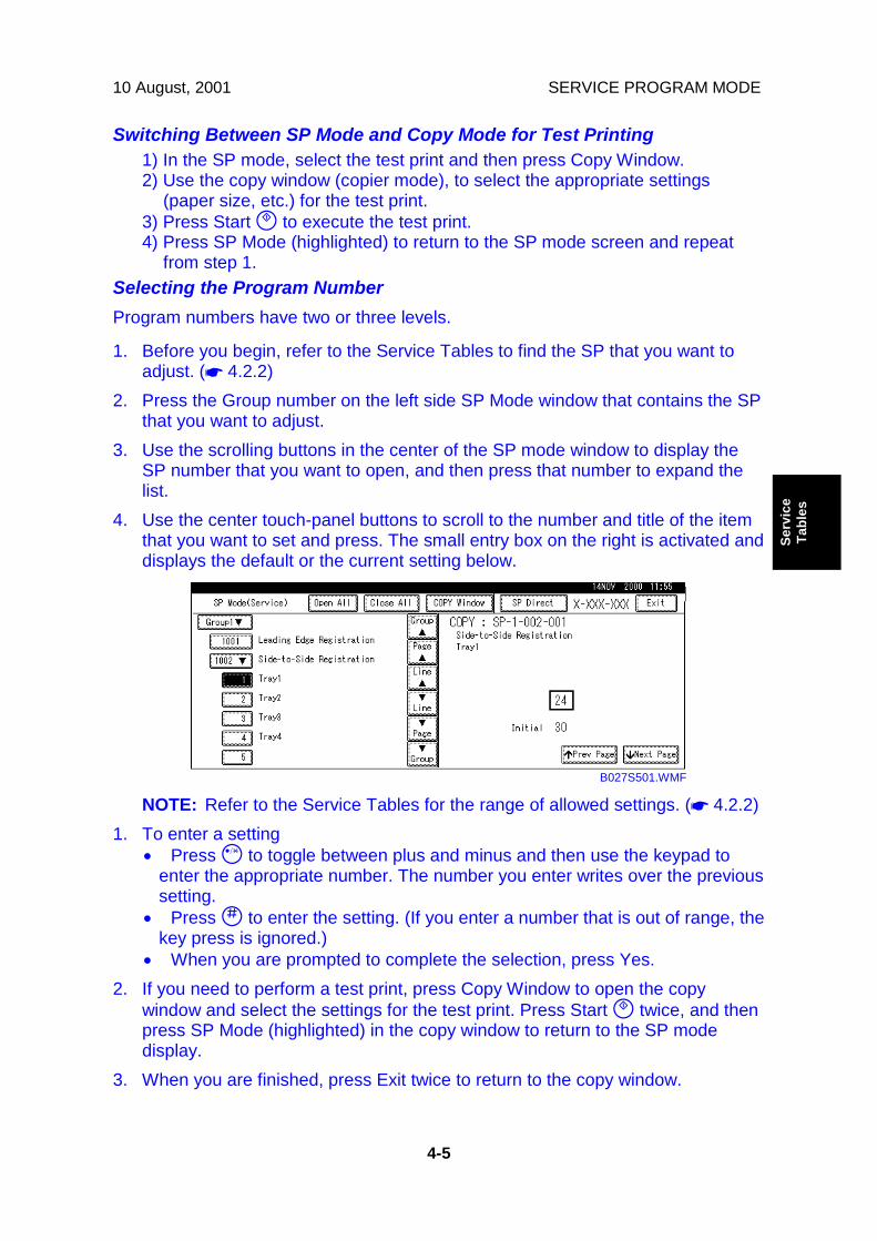
10 August, 2001 SERVICE PROGRAM MODE
4-5
Serv
ice
Tabl
es
Switching Between SP Mode and Copy Mode for Test Printing1) In the SP mode, select the test print and then press Copy Window.2) Use the copy window (copier mode), to select the appropriate settings
(paper size, etc.) for the test print.3) Press Start ( to execute the test print.4) Press SP Mode (highlighted) to return to the SP mode screen and repeat
from step 1.Selecting the Program NumberProgram numbers have two or three levels.
1. Before you begin, refer to the Service Tables to find the SP that you want toadjust. (☛ 4.2.2)
2. Press the Group number on the left side SP Mode window that contains the SPthat you want to adjust.
3. Use the scrolling buttons in the center of the SP mode window to display theSP number that you want to open, and then press that number to expand thelist.
4. Use the center touch-panel buttons to scroll to the number and title of the itemthat you want to set and press. The small entry box on the right is activated anddisplays the default or the current setting below.
NOTE: Refer to the Service Tables for the range of allowed settings. (☛ 4.2.2)1. To enter a setting
• Press ! to toggle between plus and minus and then use the keypad toenter the appropriate number. The number you enter writes over the previoussetting.
• Press ' to enter the setting. (If you enter a number that is out of range, thekey press is ignored.)
• When you are prompted to complete the selection, press Yes.2. If you need to perform a test print, press Copy Window to open the copy
window and select the settings for the test print. Press Start ( twice, and thenpress SP Mode (highlighted) in the copy window to return to the SP modedisplay.
3. When you are finished, press Exit twice to return to the copy window.
B027S501.WMF

SERVICE PROGRAM MODE 10 August, 2001
4-6
4.2.2 SERVICE PROGRAM MODE TABLESService Table Key
Notation What it means[range / default /step]
Example: [-9 ~ +9 / +3.0 / 0.1 mm step]. The setting can beadjusted in the range ±9, the setting is reset to +3.0 after anNVRAM reset, and the value can be changed in 0.1 mm stepswith each key press.
italics Comments added for reference.* Value stored in NVRAM. After a RAM reset, this default value
(factory setting) is restored.1111 An SP number set in bold-italic denotes a “Special Service
Program” mode setting that appears only after entering the SPmode by pressing ' and Copy SP together. (☛ 4.2.1)
DFU Denotes “Design or Factory Use”. Do not change this value.Japan only The feature or item is for Japan only. Do not change this value.(S) Sideways feed direction(L) Lengthwise feed direction
SP1-XXX: Feed
1 Mode Number/Name Function/[Setting]Leading Edge Registration
1 Paper Tray Feed2 By-pass Feed
001*
3 Duplex, Side2
Adjusts the printing leading edge registration fromeach paper feed station using the Trimming AreaPattern (SP4-417, No.15).Use the ! key to toggle between + and – beforeentering the value.The specification is 3 ± 2 mm.See “Replacement and Adjustment - Copy Adjustment”for details.[+9.0 ~ –9.0 / +0.0 / 0.1 mm/step]
Side-to-Side Registration1 1st Paper Feed2 2nd Paper Feed3 3rd Paper Feed:
optional PFU tray 1 oroptional LCT
4 4th Paper Feed:optional PFU tray 2
5 By-pass Feed
002*
6 Duplex, Side2
Adjusts the printing side-to-side registration from eachpaper feed station using the Trimming Area Pattern(SP4-417, No.15).Use the ! key to toggle between + and – beforeentering the value. The specification is 2 ± 1.5 mm.See “Replacement and Adjustment - Copy Adjustment”for details.[+9.0 ~ –9.0 / +0.0 / 0.1 mm/step]
Paper Feed Timing1 1st Paper Feed2 2nd, 3rd, 4th Paper
Feed, LCT, and By-passFeed
Adjusts the paper feed clutch timing at registration.The paper feed clutch timing determines the amount ofpaper buckle at registration. (A larger setting leads tomore buckling.)[0 ~ 10 / 5 / 1 mm/step]
003*
3 Duplex, Side2 [0 ~ 20 / 6 / 1 mm/step]

10 August, 2001 SERVICE PROGRAM MODE
4-7
Serv
ice
Tabl
es
1 Mode Number/Name Function/[Setting]By-pass Paper Size Display007
Displays the by-pass paper width sensor output.Fusing Idling103
Switches fusing idling on/off.Switch on if fusing on the 1st and 2nd copies isincomplete (this may occur if the room is cold.)[1 = On / 0 = Off]
Fusing Temperature Adjustment1 Roller Center2 Roller Ends
Adjusts the fusing temperature at the center and bothends of the hot roller for normal printing.[120 ~ 200 / 165 / 1°C/step]
3 Energy Saver Adjusts the fusing temperature at the center and bothends of the hot roller for energy saver mode.[0 ~ 160 / 150 / 1°C/step]
4 Thick Paper (Center)5 Thick Paper (Ends)
Adjusts the additional fusing temperature for thickpaper for the 2nd paper tray and for the bypass tray.[0 ~ 160 / 20 / 1°C/step]
6 After Warming-up(Center)
Adjusts the fusing temperature at the center of the hotroller after the machine has warmed up.[120 ~ 220 / 165 / 1°C/step]
7 After Warming-up(Ends)
Adjusts the fusing temperature at both ends of the hotroller after the machine has warmed up.[120 ~ 220 / 175 / 1°C/step]
8 Number of Pages In this machine, fusing temperature is kept 10°C higherthan the normal temperature for a number of pagesafter the machine has warmed up. This SP selects thenumber of pages made at this temperature. SeeDetailed Section Descriptions – Fusing for moredetails.[0 ~ 10 / 3 / 1 page/step]
105*
9 Times In this machine, fusing temperature is kept 10°C higherthan the normal temperature for a short while after themachine been warmed up. This SP selects the lengthof time that this temperature is used. See DetailedSection Descriptions – Fusing for more details.[0 ~ 180 / 60 / 1s/step]
Fusing Temp. Display1 Roller Center2 Roller Ends
Displays the fusing temperature for the center or bothends of the hot roller.
106
3 In the Machine at PowerOn
Displays the temperature in the machine at power on.This temperature is monitored by the thermistor on theSBCU board.
Fusing Soft Start Setting108*1 Selects whether the fusing temperature control cycle is
1 or 3 seconds.If this is “1 (3 s)”, the power supply fluctuation causedby the fusing lamp turning on is less often.[0 = 1 s / 1 = 3 s]Default: 0 = N. America, 1 = Europe/Asia
Ricoh Technical Services
RTB 11a SP 1-103-2 added
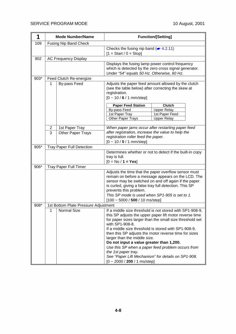
SERVICE PROGRAM MODE 10 August, 2001
4-8
1 Mode Number/Name Function/[Setting]Fusing Nip Band Check109
Checks the fusing nip band (☛ 4.2.11)[1 = Start / 0 = Stop]
AC Frequency Display902Displays the fusing lamp power control frequencywhich is detected by the zero cross signal generator.Under “54” equals 50 Hz. Otherwise, 60 Hz.
Feed Clutch Re-energize1 By-pass Feed Adjusts the paper feed amount allowed by the clutch
(see the table below) after correcting the skew atregistration.[0 ~ 10 / 6 / 1 mm/step]
2 1st Paper Tray
903*
3 Other Paper TraysWhen paper jams occur after restarting paper feedafter registration, increase the value to help theregistration roller feed the paper.[0 ~ 10 / 0 / 1 mm/step]
Tray Paper Full Detection905*Determines whether or not to detect if the built-in copytray is full.[0 = No / 1 = Yes]
Tray Paper Full Timer906*Adjusts the time that the paper overflow sensor mustremain on before a message appears on the LCD. Thesensor may be switched on and off again if the paperis curled, giving a false tray full detection. This SPprevents this problem.This SP mode is used when SP1-905 is set to 1.[100 ~ 5000 / 500 / 10 ms/step]
1st Bottom Plate Pressure Adjustment908*1 Normal Size If a middle size threshold is not stored with SP1-908-9,
this SP adjusts the upper paper lift motor reverse timefor paper sizes larger than the small size threshold setwith SP1-908-8.If a middle size threshold is stored with SP1-908-9,then this SP adjusts the motor reverse time for sizeslarger than the middle size.Do not input a value greater than 1,200.Use this SP when a paper feed problem occurs fromthe 1st paper tray.See “Paper Lift Mechanism” for details on SP1-908.[0 ~ 2000 / 200 / 1 ms/step]
Paper Feed Station ClutchBy-pass Feed Upper Relay1st Paper Tray 1st Paper FeedOther Paper Trays Upper Relay

10 August, 2001 SERVICE PROGRAM MODE
4-9
Serv
ice
Tabl
es
1 Mode Number/Name Function/[Setting]2 Small Size Adjusts the upper paper lift motor reverse time for
paper of the same size as or smaller than the smallsize threshold set with SP1-908-8.Do not input a value greater than 1200.Use this SP when a paper feed problem occurs fromthe 1st paper tray.See “Paper Lift Mechanism” for details on SP1-908.[0 ~ 2000 / 600 / 1 ms/step]
3 Middle Size Adjusts the upper paper lift motor reverse time forpaper sizes larger than the small size threshold setwith SP1-908-8, up to and including the middle sizethreshold set with SP1-908-9. If a middle sizethreshold is not stored with SP1-908-9, this SP is notused.Do not input a value greater than 1200.Use this SP when a paper feed problem occurs fromthe 1st paper tray.See “Paper Lift Mechanism” for details on SP1-908.[0 ~ 2000 / 200 / 1 ms/step]
1st Bottom Plate Pressure Re-adjustment4 Small Size Adjusts the upper paper lift motor forward rotation time
for paper of the same size as or smaller than the smallsize threshold set with SP1-908-8. The motor rotatesforward when the remaining paper amount is lowerthan the value of SP1-908-6.Use this SP when a paper feed problem occurs whenpaper in the 1st paper tray is running low.See “Paper Lift Mechanism” for details on SP1-908.[0 ~ 2000 / 400 / 1 ms/step]
5 Middle Size Adjusts the upper paper lift motor forward rotation timefor paper sizes larger than the small size threshold setwith SP1-908-8, up to and including the middle sizethreshold set with SP1-908-9.The motor rotates forward when the amount ofremaining paper is lower than the value of SP1-908-7.If a middle size threshold is not stored with SP1-908-9,this SP is not used.Use this SP when a paper feed problem occurs whenpaper in the 1st paper tray is running low.See “Paper Lift Mechanism” for details on SP1-908.[0 ~ 2000 / 300 / 1 ms/step]
1st Paper Amount6 Small Size Selects the remaining paper amount limit for use with
SP1-908-4.Set this SP to 2 or 3 when a paper feed problemoccurs before near-end.See “Paper Lift Mechanism” for details on SP1-908.[0 = None (Empty) / 1 = Near End / 2 = 25% / 3 = 75%]
908*
7 Middle Size Selects the remaining paper amount limit for use withSP1-908-5.Set this SP to 2 or 3 when a paper feed problemoccurs before near-end.See “Paper Lift Mechanism” for details on SP1-908.[0 = None (Empty) / 1 = Near End / 2 = 25% / 3 = 75%]

SERVICE PROGRAM MODE 10 August, 2001
4-10
1 Mode Number/Name Function/[Setting]1st Paper Size
8 1st Small Paper SizeSetting
Selects the small size threshold for the 1st paper tray.“0” means that this setting is not used.The size used by SP1-908 is determined by paperwidth. See “Paper Lift Mechanism” for details on SP1-908.[0 = None (Not used) / 1 = HLT/A5 / 2 = A4 / 3 = LT / 4= DLT / 5 = A3]
908*
9 1st Middle Paper SizeSetting
Selects the middle size threshold for the upper tray.“0” means that this setting is not used.The value must be larger than the small size threshold(SP1-908-8). The size used by SP1-908 is determinedby paper width. See “Paper Lift Mechanism” for detailson SP1-908.[0 = None (Not used) / 1 = HLT/A5 / 2 = A4 / 3 = LT /4 = DLT / 5 = A3]
2nd Bottom Plate Pressure Adjustment1 Normal Size If a middle size threshold is not stored with SP1-909-9,
this SP adjusts the upper paper lift motor reverse timefor paper sizes larger than the small size threshold setwith SP1-909-8.If a middle size threshold is stored with SP1-909-9,then this SP adjusts the motor reverse time for sizeslarger than the middle size.Do not input a value greater than 1,200.Use this SP when a paper feed problem occurs fromthe 2nd paper tray.See “Paper Lift Mechanism” for details on SP1-909.[0 ~ 2000 / 200 / 1 ms/step]
2 Small Size Adjusts the upper paper lift motor reverse time forpaper of the same size as or smaller than the smallsize threshold set with SP1-909-8.Do not input a value greater than 1,200.Use this SP when a paper feed problem occurs fromthe 2nd paper tray.See “Paper Lift Mechanism” for details on SP1-909.[0 ~ 2000 / 600 / 1 ms/step]
909*
3 Middle Size Adjusts the upper paper lift motor reverse time forpaper sizes larger than the small size threshold setwith SP1-909-8, up to and including the middle sizethreshold set with SP1-909-9. If a middle sizethreshold is not stored with SP1-909-9, this SP is notused.Do not input a value greater than 1200.Use this SP when a paper feed problem occurs fromthe 2nd paper tray.See “Paper Lift Mechanism” for details on SP1-909.[0 ~ 2000 / 200 / 1 ms/step]

10 August, 2001 SERVICE PROGRAM MODE
4-11
Serv
ice
Tabl
es
1 Mode Number/Name Function/[Setting]2nd Bottom Plate Pressure Re-adjustment
4 Small Size Adjusts the upper paper lift motor forward rotation timefor paper of the same size as or smaller than the smallsize threshold set with SP1-909-8. The motor rotatesforward when the remaining paper amount is lowerthan the value of SP1-909-6.Use this SP when a paper feed problem occurs whenpaper in the 2nd paper tray is running low.See “Paper Lift Mechanism” for details on SP1-909.[0 ~ 2000 / 400 / 1 ms/step]
5 Middle Size Adjusts the upper paper lift motor forward rotation timefor paper sizes larger than the small size threshold setwith SP1-909-8, up to and including the middle sizethreshold set with SP1-909-9.The motor rotates forward when the remaining paperamount is lower than the value of SP1-909-7.If a middle size threshold is not stored with SP1-909-9,this SP is not used.Use this SP when a paper feed problem occurs whenpaper in the 2nd paper tray is running low.See “Paper Lift Mechanism” for details on SP1-909.[0 ~ 2000 / 300 / 1 ms/step]
2nd Paper Amount6 Small Size Selects the remaining paper amount limit for use with
SP1-909-4.Set this SP to 2 or 3 when a paper feed problemoccurs before near-end.See “Paper Lift Mechanism” for details on SP1-909.[0 = None (Empty) / 1 = Near End / 2 = 25% / 3 = 75%]
7 Middle Size Set this SP to 2 or 3 when a paper feed problemoccurs before near-end.See “Paper Lift Mechanism” for details on SP1-909.
2nd Paper Size8 2nd Small Paper Size
SettingSelects the small size threshold for the 2nd paper tray.“0” means that this setting is not used.The size used by SP1-909 is determined by paperwidth. See “Paper Lift Mechanism” for details on SP1-909.[0 = None (Not used) / 1 = HLT/A5 / 2 = A4 / 3 = LT / 4= DLT / 5 = A3]
909*
9 2nd Middle Paper SizeSetting
Selects the middle size threshold for the upper tray.“0” means that this setting is not used.The value must be larger than the small size threshold(SP1-909-8). The size used by SP1-909 is determinedby paper width. See “Paper Lift Mechanism” for detailson SP1-909.[0 = None (Not used) / 1 = HLT/A5 / 2 = A4 / 3 = LT /4 = DLT / 5 = A3]

SERVICE PROGRAM MODE 10 August, 2001
4-12
1 Mode Number/Name Function/[Setting]3rd Bottom Plate Pressure Adjustment
1 Normal Size(Optional PFU)
If a middle size threshold is not stored with SP1-910-9,this SP adjusts the upper paper lift motor reverse timefor paper sizes larger than the small size threshold setwith SP1-910-8.If a middle size threshold is stored with SP1-910-9,then this SP adjusts the motor reverse time for sizeslarger than the middle size.Do not input a value greater than 1200.Use this SP when a paper feed problem occurs fromthe 3rd paper tray.See “Optional Paper Tray Unit - Paper Lift Mechanism”for details on SP1-910.[0 ~ 2000 / 200 / 1 ms/step]
2 Small Size(Optional PFU)
Adjusts the upper paper lift motor reverse time forpaper of the same size as or smaller than the smallsize threshold set with SP1-910-8.Do not input a value greater than 1200.Use this SP when a paper feed problem occurs fromthe 3rd paper tray.See “Optional Paper Tray Unit - Paper Lift Mechanism”for details on SP1-910.[0 ~ 2000 / 600 / 1 ms/step]
3 Middle Size(Optional PFU)
Adjusts the upper paper lift motor reverse time forpaper sizes larger than the small size threshold setwith SP1-910-8, up to and including the middle sizethreshold set with SP1-910-9. If a middle sizethreshold is not stored with SP1-910-9, this SP is notused.Do not input a value greater than 1200.Use this SP when a paper feed problem occurs fromthe 3rd paper tray.See “Optional Paper Tray Unit - Paper Lift Mechanism”for details on SP1-910.[0 ~ 2000 / 200 / 1 ms/step]
3rd Bottom Plate Pressure Re-adjustment
910*
4 Small Size(Optional PFU)
Adjusts the upper paper lift motor forward rotation timefor paper of the same size as or smaller than the smallsize threshold set with SP1-910-8. The motor rotatesforward when the remaining paper amount is lowerthan the value of SP1-910-6.Use this SP when a paper feed problem occurs whenpaper in the 3rd paper tray is running low.See “Optional Paper Tray Unit - Paper Lift Mechanism”for details on SP1-910.[0 ~ 2000 / 400 / 1 ms/step]
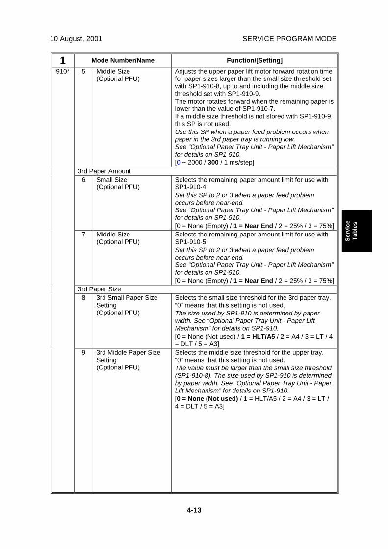
10 August, 2001 SERVICE PROGRAM MODE
4-13
Serv
ice
Tabl
es
1 Mode Number/Name Function/[Setting]5 Middle Size
(Optional PFU)Adjusts the upper paper lift motor forward rotation timefor paper sizes larger than the small size threshold setwith SP1-910-8, up to and including the middle sizethreshold set with SP1-910-9.The motor rotates forward when the remaining paper islower than the value of SP1-910-7.If a middle size threshold is not stored with SP1-910-9,this SP is not used.Use this SP when a paper feed problem occurs whenpaper in the 3rd paper tray is running low.See “Optional Paper Tray Unit - Paper Lift Mechanism”for details on SP1-910.[0 ~ 2000 / 300 / 1 ms/step]
3rd Paper Amount6 Small Size
(Optional PFU)Selects the remaining paper amount limit for use withSP1-910-4.Set this SP to 2 or 3 when a paper feed problemoccurs before near-end.See “Optional Paper Tray Unit - Paper Lift Mechanism”for details on SP1-910.[0 = None (Empty) / 1 = Near End / 2 = 25% / 3 = 75%]
7 Middle Size(Optional PFU)
Selects the remaining paper amount limit for use withSP1-910-5.Set this SP to 2 or 3 when a paper feed problemoccurs before near-end.See “Optional Paper Tray Unit - Paper Lift Mechanism”for details on SP1-910.[0 = None (Empty) / 1 = Near End / 2 = 25% / 3 = 75%]
3rd Paper Size8 3rd Small Paper Size
Setting(Optional PFU)
Selects the small size threshold for the 3rd paper tray.“0” means that this setting is not used.The size used by SP1-910 is determined by paperwidth. See “Optional Paper Tray Unit - Paper LiftMechanism” for details on SP1-910.[0 = None (Not used) / 1 = HLT/A5 / 2 = A4 / 3 = LT / 4= DLT / 5 = A3]
910*
9 3rd Middle Paper SizeSetting(Optional PFU)
Selects the middle size threshold for the upper tray.“0” means that this setting is not used.The value must be larger than the small size threshold(SP1-910-8). The size used by SP1-910 is determinedby paper width. See “Optional Paper Tray Unit - PaperLift Mechanism” for details on SP1-910.[0 = None (Not used) / 1 = HLT/A5 / 2 = A4 / 3 = LT /4 = DLT / 5 = A3]

SERVICE PROGRAM MODE 10 August, 2001
4-14
1 Mode Number/Name Function/[Setting]4th Bottom Plate Pressure Adjustment
1 Normal Size(Optional PFU)
If a middle size threshold is not stored with SP1-911-9,this SP adjusts the upper paper lift motor reverse timefor paper sizes larger than the small size threshold setwith SP1-911-8.If a middle size threshold is stored with SP1-911-9,then this SP adjusts the motor reverse time for sizeslarger than the middle size.Do not input a value greater than 1200.Use this SP when a paper feed problem occurs fromthe 4th paper tray.See “Optional Paper Tray Unit - Paper Lift Mechanism”for details on SP1-911.[0 ~ 2000 / 200 / 1 ms/step]
2 Small Size(Optional PFU)
Adjusts the upper paper lift motor reverse time forpaper of the same size as or smaller than the smallsize threshold set with SP1-911-8.Do not input a value greater than 1200.Use this SP when a paper feed problem occurs fromthe 4th paper tray.See “Optional Paper Tray Unit - Paper Lift Mechanism”for details on SP1-911.[0 ~ 2000 / 600 / 1 ms/step]
3 Middle Size(Optional PFU)
Adjusts the upper paper lift motor reverse time forpaper sizes larger than the small size threshold setwith SP1-911-8, up to and including the middle sizethreshold set with SP1-911-9. If a middle sizethreshold is not stored with SP1-911-9, this SP is notused.Do not input a value greater than 1200.Use this SP when a paper feed problem occurs fromthe 4th paper tray.See “Optional Paper Tray Unit - Paper Lift Mechanism”for details on SP1-911.[0 ~ 2000 / 200 / 1 ms/step]
4th Bottom Plate Pressure Re-adjustment
911*
4 Small Size(Optional PFU)
Adjusts the upper paper lift motor forward rotation timefor paper of the same size as or smaller than the smallsize threshold set with SP1-911-8. The motor rotatesforward when the remaining paper amount is lowerthan the value of SP1-911-6.Use this SP when a paper feed problem occurs whenpaper in the 4th paper tray is running low.See “Optional Paper Tray Unit - Paper Lift Mechanism”for details on SP1-911.[0 ~ 2000 / 400 / 1 ms/step]

10 August, 2001 SERVICE PROGRAM MODE
4-15
Serv
ice
Tabl
es
1 Mode Number/Name Function/[Setting]5 Middle Size
(Optional PFU)Adjusts the upper paper lift motor forward rotation timefor paper sizes larger than the small size threshold setwith SP1-911-8, up to and including the middle sizethreshold set with SP1-911-9.The motor rotates forward when the remaining paperamount is lower than the value of SP1-911-7.If a middle size threshold is not stored with SP1-911-9,this SP is not used.Use this SP when a paper feed problem occurs whenpaper in the 4th paper tray is running low.See “Optional Paper Tray Unit - Paper Lift Mechanism”for details on SP1-911.[0 ~ 2000 / 300 / 1 ms/step]
4th Paper Amount6 Small Size
(Optional PFU)Selects the remaining paper amount limit for use withSP1-911-4.Set this SP to 2 or 3 when a paper feed problemoccurs before near-end.See “Optional Paper Tray Unit - Paper Lift Mechanism”for details on SP1-911.[0 = None (Empty) / 1 = Near End / 2 = 25% / 3 = 75%]
7 Middle Size(Optional PFU)
Selects the remaining paper amount limit for use withSP1-911-5.Set this SP to 2 or 3 when a paper feed problemoccurs before near-end.See “Optional Paper Tray Unit - Paper Lift Mechanism”for details on SP1-911.[0 = None (Empty) / 1 = Near End / 2 = 25% / 3 = 75%]
4th Paper Size8 4th Small Paper Size
Setting(Optional PFU)
Selects the small size threshold for the 4th paper tray.“0” means that this setting is not used.The size used by SP1-911 is determined by paperwidth. See “Optional Paper Tray Unit - Paper LiftMechanism” for details on SP1-911.[0 = None (Not used) / 1 = HLT/A5 / 2 = A4 / 3 = LT / 4= DLT / 5 = A3]
911*
9 4th Middle Paper SizeSetting(Optional PFU)
Selects the middle size threshold for the upper tray.“0” means that this setting is not used.The value must be larger than the small size threshold(SP1-911-8). The size used by SP1-911 is determinedby paper width. See “Optional Paper Tray Unit - PaperLift Mechanism” for details on SP1-911.[0 = None (Not used) / 1 = HLT/A5 / 2 = A4 / 3 = LT /4 = DLT / 5 = A3]
Tray Motor Reverse Time912*Adjusts the tray motor reverse time.The tray motor reverses when the tray is pulled out.The tray can be put back in the machine withoutdamage while the motor reverses.[0 ~ 9000 / 1700 / 1 ms/step]

SERVICE PROGRAM MODE 10 August, 2001
4-16
1 Mode Number/Name Function/[Setting]Punch Hole Detection994
When using paper that has punch holes, theregistration sensor may detect the hole and a paperjam will be detected. If you select “1”, the machineignores the registration sensor off signal within 50 mmfrom the trailing edge of the paper.[0 = No 1 = Yes]
SP2-XXX: Drum
2 Mode Number/Name Function/[Setting]Charge Roller Bias Adjustment1* Printing Adjusts the voltage applied to the charge roller during
printing.This value will be changed automatically when thecharge roller bias correction is performed.Note that if this value is changed, the charge rollervoltage will be corrected based on the new voltage.[2100 ~ 1500 / –1700 / 1 V/step]
2* Charge Roller BiasAdjustment(ID sensor pattern)
Adjusts the voltage applied to the charge roller whenmaking the Vsdp ID sensor pattern (for charge rollerbias correction).The actual charge roller voltage is this value plus thevalue of SP2-001-1.[0 ~ 400 / 200 / 1 V/step]
001*
3 Charge Roller BiasAdjustment(Temporally input)
Inputs the charge roller voltage temporarily for testpurposes.Do not change the value.[0 ~ –2500 / 0 / 1 V/step]
Charge Roller Bias Correction1 Vsdp Minimum Adjusts the lower threshold value for the charge roller
correction.When the value of Vsdp/Vsg is less than this value, thecharge roller voltage increases by 50V (e.g. from –500to –550). The size of the increase depends on SP2-005-3.[0 ~ 100 / 90 / 1%/step]
2 Vsdp Maximum Adjusts the upper threshold value for the charge rollercorrection.When the value of Vsdp/Vsg is greater than this value,the charge roller voltage decreases by 50V (e.g. from –550 to –500). The size of the decrease depends onSP2-005-3.[0 ~ 100 / 95 / 1 %/step]
005*
3 Step Adjusts the size of the charge roller voltage correction.[0 ~ 200 / 50 / 1 V/step]

10 August, 2001 SERVICE PROGRAM MODE
4-17
Serv
ice
Tabl
es
2 Mode Number/Name Function/[Setting]Erase Margin Adjustment
1 Leading Edge Adjusts the leading edge erase margin.The specification is 3 ± 2 mm. See “Replacement andAdjustment - Copy Adjustment” for details.[0.0 ~ 9.0 / 3.0 / 0.1 mm/step]
2 Trailing Edge – SmallPaper Size
Adjusts the trailing edge erase margin for paper oflength 216 mm or less.The specification is 3 ± 2 mm. See “Replacement andAdjustment - Copy Adjustment” for details.[0.0 ~ 9.0 / 2.0 / 0.1 mm/step]
3 Trailing Edge – MiddlePaper Size
Adjusts the trailing edge erase margin for paper oflength 216.1 ~ 297 mm.The specification is 3 ± 2 mm. See “Replacement andAdjustment - Copy Adjustment” for details.[0.0 ~ 9.0 / 3.0 / 0.1 mm/step]
4 Trailing Edge – LargePaper Size
Adjusts the trailing edge erase margin for paper longerthan 297 mm.The specification is 3 ± 2 mm. See “Replacement andAdjustment - Copy Adjustment” for details.[0.0 ~ 9.0 / 4.0 / 0.1 mm/step]
5 Left Side Adjusts the left edge erase margin.The specification is 2 ± 1.5 mm. See “Replacementand Adjustment - Copy Adjustment” for details.[0.0 ~ 9.0 / 2.0 / 0.1 mm/step]
6 Right Side Adjusts the right edge erase margin.The specification is 2 + 2.5/-1.5 mm. See“Replacement and Adjustment - Copy Adjustment” fordetails.[0.0 ~ 9.0 / 2.0 / 0.1 mm/step]
7 Rear – Trailing Edge Adjusts the trailing edge erase margin on the reverseside of duplex copies.The actual trailing edge erase margin on the reverseside is this value plus the value of SP2-101-2 or 3 or 4.The specification is 3 ± 2 mm. See “Replacement andAdjustment - Copy Adjustment” for details[0.0 ~ 9.0 / 1.2 / 0.1 mm/step]
8 Rear – Left Side Adjusts the left side erase margin on the reverse sideof duplex copies.The actual left side erase margin on the reverse side isthis value plus the value of SP2-101-5.The specification is 2 ± 1.5 mm. See “Replacementand Adjustment - Copy Adjustment” for details.[0.0 ~ 9.0 / 0.3 / 0.1 mm/step]
101*
9 Rear – Right Side Adjusts the right side erase margin on the reverse sideof duplex copies.The actual right side erase margin on the reverse sideis this value plus the value of SP2-101-6.The specification is 2 +2.5/–1.5 mm. See“Replacement and Adjustment - Copy Adjustment” fordetails.[0.0 ~ 9.0 / 0.3 / 0.1 mm/step]

SERVICE PROGRAM MODE 10 August, 2001
4-18
2 Mode Number/Name Function/[Setting]101* 10 Printer, Rear Trailing
EdgeIn printer mode, adjusts the trailing edge erase marginon the reverse side of duplex copies.The actual trailing edge erase margin on the reverseside is this value plus the value of SP2-101-7.The specification is 3 ± 2 mm. See “Replacement andAdjustment - Copy Adjustment” for details[0.0 ~ 9.0 / 0.0 / 0.1 mm/step]
LD Power Adjustment103*Adjusts the LD power. DFUDo not change the value.[50 ~ 170 / 129 / 1/step]
Test Mode dpi110*Sets the scanning resolution (dpi). DFU[See below / 8 / 0~18] 0: 400x400 dpi 1: 391x406 dpi 2: 406x391 dpi 4: 300x300 dpi 8: 600x600 dpi 15: 439x430 dpi16: 476x476 dpi 17: 483x465 dpi18: 465x483 dpi
Development Bias Adjustment1 Printing Adjusts the development bias during printing.
This can be adjusted as a temporary measure if faintcopies appear due to an aging drum.[–1500 ~ 2000 / –650 / 1 V/step]
201*
2 ID sensor pattern Adjusts the development bias for making the ID sensorpattern.The actual development voltage for the ID sensorpattern is this value plus the value of SP2-201-1.This should not be used in the field, because it affectsID sensor pattern density, which affects toner supply.[0 = N (200V) / 1 = H (240V) / 2 = L (160V) / 3 = HH(280V) / 4 = LL (120V)]
Bias Off Time1 Charge Bias Adjusts the charge voltage (-1200V) application time.
DFUWhen the charge voltage and development bias areturned off at the same time, toner or carrier will beattracted to the drum. To reduce the toner or carrierattraction, the machine applies –1200V to the chargeroller before the development bias is turned off. ThisSP adjusts the time for applying the charge.[0 ~ 150 / 80 / 1 ms /step]
210*
2 Development Bias Adjusts the development bias off time.DFU[-120 ~ 120 / 0 / 1ms/step]

10 August, 2001 SERVICE PROGRAM MODE
4-19
Serv
ice
Tabl
es
2 Mode Number/Name Function/[Setting]PCU Reverse Interval211*
Adjusts the PCU reverse interval for cleaning during ajob.When the machine has made this number of copies inthe middle of a job, the machine reverses to clean theedge of the cleaning blade. After cleaning, the machineresumes the job. Set to a shorter interval if thin whitelines appear on printouts.0: Cleaning is never done in the middle of a job[0 ~ 999 / 100 / 1 sheet/step]
Copies after Near End213*Selects the number of copies that can be made aftertoner near-end has been detected.If the user normally makes copies with a highproportion of black, reduce the interval.[0 = 50 pages / 1 = 20 pages]
Vt/Vsg/Vsp/Vsdp/Vts Data Display1 Vsp2 Vsg3 Vsdp4 Vt
220*
5 Vts
Displays the Vt, Vsg, Vsp, Vsdp, and Vts values.
Transfer Current1* Normal Paper Adjusts the current applied to the transfer roller during
copying from a paper tray when the user uses the“Normal” paper setting.If the user normally feeds thicker paper from a papertray, use a higher setting.[0 = –2 µA / 1 = 0 µµµµA / 2 = +2 µA / 3 = +4 µA]
2* Thick/Thin Paper Adjusts the current applied to the transfer roller duringcopying from the by-pass tray. These settings are alsoused if the 2nd tray is used and special paper isselected.If the user normally feeds thicker paper from the by-pass tray/2nd tray (special paper), use a higher setting.If waste toner is re-attracted from the drum (this canoccur when using an OHP sheet), use a higher setting.[0 = –2 µA / 1 = 0 µµµµA / 2 = +2 µA / 3 = +4 µA]
3* Duplex, Side2 Adjusts the current applied to the transfer roller duringcopying from the duplex unit when the user uses the“Normal” paper setting.Use this SP when the image on the rear side of thepaper has a problem caused by poor image transfer.[0 = –2 µA / 1 = 0 µµµµA / 2 = +2 µA / 3 = +4 µA]
4* Cleaning Adjusts the current applied to the transfer roller duringroller cleaning.If toner remains on the roller after cleaning (dirtybackground appears on the rear side of the paper),increase the current.[0 ~ 10 / –4 / 1 µA/step]
301*
5 Input – Front This is for the designer’s test purposes.Do not change the value.[0 ~ 30 / 0 / 1 µA/step]
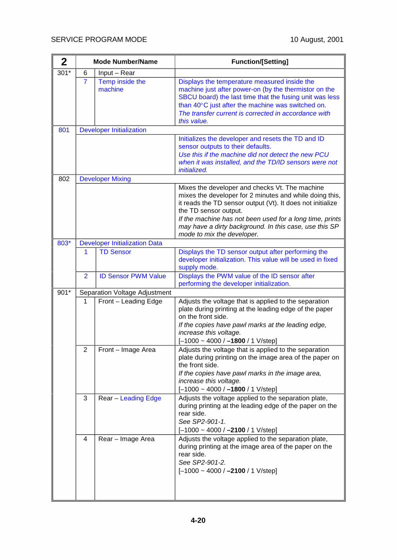
SERVICE PROGRAM MODE 10 August, 2001
4-20
2 Mode Number/Name Function/[Setting]6 Input – Rear301*7 Temp inside the
machineDisplays the temperature measured inside themachine just after power-on (by the thermistor on theSBCU board) the last time that the fusing unit was lessthan 40°C just after the machine was switched on.The transfer current is corrected in accordance withthis value.
Developer Initialization801Initializes the developer and resets the TD and IDsensor outputs to their defaults.Use this if the machine did not detect the new PCUwhen it was installed, and the TD/ID sensors were notinitialized.
Developer Mixing802Mixes the developer and checks Vt. The machinemixes the developer for 2 minutes and while doing this,it reads the TD sensor output (Vt). It does not initializethe TD sensor output.If the machine has not been used for a long time, printsmay have a dirty background. In this case, use this SPmode to mix the developer.
Developer Initialization Data1 TD Sensor Displays the TD sensor output after performing the
developer initialization. This value will be used in fixedsupply mode.
803*
2 ID Sensor PWM Value Displays the PWM value of the ID sensor afterperforming the developer initialization.
Separation Voltage Adjustment1 Front – Leading Edge Adjusts the voltage that is applied to the separation
plate during printing at the leading edge of the paperon the front side.If the copies have pawl marks at the leading edge,increase this voltage.[–1000 ~ 4000 / –1800 / 1 V/step]
2 Front – Image Area Adjusts the voltage that is applied to the separationplate during printing on the image area of the paper onthe front side.If the copies have pawl marks in the image area,increase this voltage.[–1000 ~ 4000 / –1800 / 1 V/step]
3 Rear – Leading Edge Adjusts the voltage applied to the separation plate,during printing at the leading edge of the paper on therear side.See SP2-901-1.[–1000 ~ 4000 / –2100 / 1 V/step]
901*
4 Rear – Image Area Adjusts the voltage applied to the separation plate,during printing at the image area of the paper on therear side.See SP2-901-2.[–1000 ~ 4000 / –2100 / 1 V/step]

10 August, 2001 SERVICE PROGRAM MODE
4-21
Serv
ice
Tabl
es
2 Mode Number/Name Function/[Setting]Test Pattern Printing902*
3 Prints the test patterns. Select the number of the testpattern that you want to print (☛ 4.2.3).When adjusting the printing registration, select no.10(Trimming Area Pattern).[0 ~ 41 / 0 / 1 step]
Tailing Correction1 Shift Value Shifts the image across the page at the interval
specified by SP2-906-2.When making many copies of an original that containsvertical lines (such as a table), separation may notwork correctly, then a tailing image will occur (ghostsof the vertical lines will continue past the bottom of thetable). This SP prevents this problem.[0.0 ~ 1.0 / 0.0 / 1 mm/step]
906*
2 Interval Changes the interval for the image shift specified bySP2-906-1.[1 ~ 10 / 0 / 1 page/step]
Line Width Correction1 Text Mode Adjusts the line width. The value “5” means that line
width correction is disabled. A number smaller than 5makes lines thinner. A number bigger than 5 makeslines thicker.
Thinnest Thickest0 – 1 – 2 – 3 – 4 – 5 – 6 – 7 – 8 – 9 – 10
[0 ~ 10 / 5 / 1 step]2 Photo Mode [0 ~ 10 / 6 / 1 step]3 Text/Photo Mode [0 ~ 10 / 5 / 1 step]4 Pale Mode [0 ~ 10 / 5 / 1 step]
907*
5 Generation Mode [0 ~ 10 / 5 / 1 step]Forced Toner Supply908
Forces the toner bottle to supply toner to the tonersupply unit.Press Execute on the touch panel to start.During this process, the machine supplies toner untilthe toner concentration in the development unitreaches a standard level. However, if the tonerconcentration does not reach a standard level, themachine supplies toner for 2 minutes maximum.
Main Scan Magnification1 Copy - Short Edge Feed Adjusts the main scan magnification in copy mode
when the machine feeds the paper in the short edgefeed orientation.[-0.5 ~ 0.5 / 0.0 / 0.1%/step]
2 Printer – Short EdgeFeed
Adjusts the main scan magnification in printer modewhen the machine feeds the paper in the short edgefeed orientation.[-0.5 ~ 0.5 / 0.0 / 0.1%/step]
909*
3 Copy – Long Edge Feed Adjusts the main scan magnification in copy modewhen the machine feeds the paper in the long edgefeed orientation.[-0.5 ~ 0.5 / 0.0 / 0.1%/step]

SERVICE PROGRAM MODE 10 August, 2001
4-22
2 Mode Number/Name Function/[Setting]909* 4 Printer – Long Edge
FeedAdjusts the main scan magnification in printer modewhen the machine feeds the paper in the long edgefeed orientation.[-0.5 ~ 0.5 / 0.0 / 0.1%/step]
Margin Adjustment for By-pass910*Adjusts the blank margin at the trailing edge of paperfed from the by-pass table.[-9.0 ~ +9.0 / 0.1 mm / 1mm/step]
ID Adjustment for Test Pattern913*Adjusts the image density level for black pixels on testpattern printouts (patterns are made with SP2-902)This SP affects all test patterns except for thegrayscale test patterns.[0 ~ 15 / 15 / 1/step]
Polygon Motor Idling Time915*Selects the polygon motor idling time.If the user sets an original, touches a key, or opens theplaten cover/DF, the polygon motor starts idling tomake a faster first copy. However, with the default (15s), the motor stops if the user does nothing for 15 s,and stops 15 s after the end of a job.If set at “0”, the polygon motor never turns off duringstand-by. However, when the machine goes intoenergy saver mode, the polygon motor turns offregardless of this timer.[0 = None / 1 = 15 s / 2 = 25 s]
Toner Supply Mode921*Selects the toner supply mode.Normally, only use setting 0. Change to 3 temporarily ifthe TD sensor is defective. Do not use settings 1 and2; these are for designer’s use only.[0 = Sensor 1 / 1 = Sensor 2 / 2 = Fixed 1 / 3 = Fixed2]
Toner Supply Time922*Adjusts the toner supply motor on time for sensorsupply mode.This SP is effective only when SP2-921 is “0” or “1”.Increasing this value increases the toner supply motoron time. So, use a high value if the user tends to makelots of copies that have a high proportion of black.[0.1 ~ 5.0 / 0.6 / 0.1 s/step]
Toner Recovery Time923*Adjusts the toner supply motor on time during recoveryfrom toner near-end/end.This SP is effective only when SP2-921 is “0”, “1”, or“2”.Note that toner recovery is done in a 3-second cycle.So, the input value should be a multiple of 3 (e.g. 3, 6,9). See “Toner Density Control” for more details.[3 ~ 60 / 30 / 1 s/step]

10 August, 2001 SERVICE PROGRAM MODE
4-23
Serv
ice
Tabl
es
2 Mode Number/Name Function/[Setting]Toner Supply Rate925*
Adjusts the toner supply rate for fixed toner supplymode.This SP is effective only when SP2-921 is “2” or “3”.Increasing this value increases the toner supply motoron time. So, use a high value if the user tends to makelots of copies that have a high proportion of black. See“Toner Density Control” for more details.
0: t 4: 12t1: 2t 5: 16t2: 4t 6: On continuously3: 8t 7: 0 s
t: 200 ms
[0 ~ 7 / 0 / 1/step]Standard Vt926*
Adjusts Vts (Vt for a new PCU). The TD sensor outputis adjusted to this value during the TD sensor initialsetting process.This SP is effective only when SP2-921 is “0”, “1”, or“2”.Do not change this value.[0.00 ~ 5.00 / 2.50 / 0.01 V/step]
ID Sensor Control927*Selects whether the ID sensor is used or not for tonerdensity control.If this value is “0”, dirty background may occur after themachine has not been used for a long time.[0 = No / 1 = Yes]
Toner End Clear928*Clears the toner end condition.Press Execute on the touch panel to clear the tonerend condition without adding new toner.If press Execute, the following are cleared.• Toner end indicator (goes out)• Toner near-end counter• Toner near-end levelWhen making a lot of copies after changing this settingto “1”, the carrier may be attracted to the drum whenthe toner runs out, which may damage the drum.
Vref1 Upper Limit Adjusts the upper limit for Vref.
[0.00 ~ 5.00 / 3.10 / 0.01 V/step]
929*
2 Lower Limit Adjusts the lower limit for Vref.[0.00 ~ 5.00 / 1.40 / 0.01 V/step]
TD Sensor Manual Setting930*Adjusts the TD sensor output. DFU[0.5 ~ 3.5 / 0.0V / 1V/step]
TD (V/wt%) Setting931*Adjusts the TD sensor sensitivity (coefficient: S) fortoner density control. DFU[0.01 ~ 1.50 / 0.4 / 0.1/step]

SERVICE PROGRAM MODE 10 August, 2001
4-24
2 Mode Number/Name Function/[Setting]Toner Density Control Level Adjustment932*
Adjusts the toner density control threshold level.[0 = Normal / 1 = Dark / 2 = Light / 3 = Darker / 4 =Lighter]Use this SP when you want to adjust the imagedensity.
ID Sensor Control Coefficient933*Adjusts the ID sensor control coefficient. DFU[5 ~ 30 / 10 / 1/step]
ID Sensor PWM Setting1 Display Displays the PWM of the ID Sensor LED.2 PWM Upper Limit Adjusts the upper limit of the PWM for the ID sensor
LED. DFU[0 ~ 999 / 0 / 1/step]
934*
3 PWM Upper LimitCorrection
Corrects the upper limit of the PWM for the ID sensorLED. DFU[0 ~ 999 / 0 / 1/step]
ID Sensor Initialization935Performs the ID sensor initial setting.Press Execute on the touch panel to start. Perform thissetting after replacing or cleaning the ID sensor.
ID Sensor Pattern Size936*Selects the ID sensor pattern size in the main scandirection.Set to 1 if white spots or black spots appear on prints.The ID sensor pattern is 290 mm wide, and when thisis cleaned off, dirt is removed also.[0 = 20 mm / 1 = 290 mm]
Copies After TD Sensor Error992*Selects the number of copies that can be made after aTD sensor error has been detected. When the machinecopies this amount, an SC condition will occur.If the optional fax unit is installed, the SC conditionoccurs immediately regardless of the number of prints(this is because the sender of the fax cannot check theimage quality of the printout).[0 = 100 copies / 1 = 200 copies]
Vts Limitation1 Upper Limit (Factory) DFU
994*
2 Lower Limit (Factory) DFUID Sensor Detection Interval995*
1 Warming-up If the machine starts warming-up after this time haspassed since entering energy saver mode or auto offmode, the machine makes an ID sensor pattern.If this value is greater, there is a greater chance thatbackground will become dirty.[0 ~ 999 / 30 / 1 minute/step]
955* 2 Number of Page The machine makes an ID sensor pattern after thespecified number of prints has been made. 0 = thisfeature is disabled.[0 ~ 999 / 0 / 1 page/step]

10 August, 2001 SERVICE PROGRAM MODE
4-25
Serv
ice
Tabl
es
2 Mode Number/Name Function/[Setting]Transfer Roller Cleaning996*
Selects whether the transfer roller is cleaned beforeeach copy job.Set this to ‘1’ when dirty background appears on thereverse side of the first page of a copy job. However,the first copy time will be longer.If this SP is at 0, the transfer roller is never cleaned.See ‘Detailed Section Descriptions – Transfer RollerCleaning” for more details.[0 = No / 1 = Yes]
997* Vts Setting (Factory) DFUPCU Reverse Rotation Time
1 Wait Time Adjusts the waiting time for starting to rotate the drumin reverse after the end of each job.The wait time calculation formula is as follows.This value x 30 ms. 0: Reverses immediately after theend of the job (no waiting)[0 ~ 99 / 20 / 1/step]
998*
2 Reverse Time Adjusts the drum reverse rotation time.The reverse rotation time calculation formula is asfollows.This value x 30 ms. 0: No reverse at end of job[0 ~ 99 / 1 / 1/step]
Toner Control Data Display999*Displays the toner density control data on the debugmonitor. DFU[0 = No / 1 = Yes]
SP4-XXX: Scanner
4 Mode Number/Name Function/[Setting]Main Scan Magnification (Scanner)008*
Adjusts the magnification in the main scan direction forscanning.Use the ! key to toggle between + and – beforeentering the value. The specification is ± 1%. See“Replacement and Adjustment - Copy Adjustment” fordetails.[–0.9 ~ +0.9 / 0.0 / 0.1% step]
Sub Scan Magnification (Scanner)009*Adjusts the magnification in the sub scan direction forscanning.Use the ! key to toggle between + and – beforeentering the value. The specification is ± 1%. See“Replacement and Adjustment - Copy Adjustment” fordetails.[–0.9 ~ +0.9 / 0.0 / 0.1% step]
Ricoh Technical Services
RTB 11a SP 2-998-1 default changed
Ricoh Technical Services
Incorrect 4-008 should be sub-scan, and 4-009 should be main scan.
Ricoh Technical Services

SERVICE PROGRAM MODE 10 August, 2001
4-26
4 Mode Number/Name Function/[Setting]Leading Edge Registration (Scanner)010*
Adjusts the leading edge registration for scanning inplaten mode.(–): The image moves in the direction of the leadingedge.Use the ! key to toggle between + and – beforeentering the value. The specification is 2 ± 1.5 mm.See “Replacement and Adjustment – CopyAdjustment” for details.[–0.9 ~ +0.9 / 0.0 / 0.1 mm step]
Side-to-side Registration (Scanner)011*Adjusts the side-to-side registration for scanning inplaten mode.(–): The image disappears at the left side.(+): The image appears.Use the ! key to toggle between + and – beforeentering the value. The specification is 2 ± 1.5 mm.See “Replacement and Adjustment - Copy Adjustment”for details.[–4.6 ~ +4.6 / 0.0 / 0.1 mm step]
Scanner Erase Margin1 Leading Edge2 Trailing Edge3 Right Side
012*
4 Left Side
Adjusts the erase margin at each side for scanning.Do not adjust this unless the user wishes to have ascanner margin that is greater than the printer margin.[0 ~ 9.0 / 0.5 / 0.1 mm/step]
Scanner Free Run013Performs a scanner free run with the exposure lampon.Press ON on the touch panel to start this feature.Press the & (Clear/Stop) key to stop.
White Plate Scanning1 Start Position Adjusts the scanning start position on the white plate
for auto shading.The default is 10.5 mm from the leading edge. Thesetting specifies how far scanning starts from thedefault position.[–5.0 ~ +5.0 / 0.0 / 0.1 mm/step]
015*
2 Scanning Area Adjusts the width of the area on the white plate (in thesub scan direction) that is scanned for auto shading.The default is 4.76 mm. The current setting specifiesthe difference from this default.[–5.0 ~ +5.0 / 0.0 / 0.1 mm/step]
APS Data Display301Displays the status of the APS sensors and platen/DFcover sensor (☛ 4.2.9).
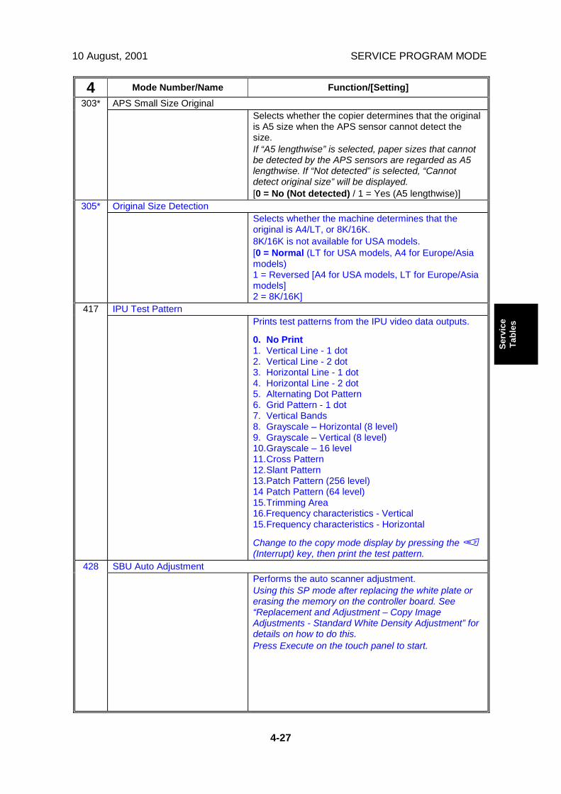
10 August, 2001 SERVICE PROGRAM MODE
4-27
Serv
ice
Tabl
es
4 Mode Number/Name Function/[Setting]APS Small Size Original303*
Selects whether the copier determines that the originalis A5 size when the APS sensor cannot detect thesize.If “A5 lengthwise” is selected, paper sizes that cannotbe detected by the APS sensors are regarded as A5lengthwise. If “Not detected” is selected, “Cannotdetect original size” will be displayed.[0 = No (Not detected) / 1 = Yes (A5 lengthwise)]
Original Size Detection305*Selects whether the machine determines that theoriginal is A4/LT, or 8K/16K.8K/16K is not available for USA models.[0 = Normal (LT for USA models, A4 for Europe/Asiamodels)1 = Reversed [A4 for USA models, LT for Europe/Asiamodels]2 = 8K/16K]
IPU Test Pattern417Prints test patterns from the IPU video data outputs.
0. No Print1. Vertical Line - 1 dot2. Vertical Line - 2 dot3. Horizontal Line - 1 dot4. Horizontal Line - 2 dot5. Alternating Dot Pattern6. Grid Pattern - 1 dot7. Vertical Bands8. Grayscale – Horizontal (8 level)9. Grayscale – Vertical (8 level)10.Grayscale – 16 level11.Cross Pattern12.Slant Pattern13.Patch Pattern (256 level)14 Patch Pattern (64 level)15.Trimming Area16.Frequency characteristics - Vertical15.Frequency characteristics - Horizontal
Change to the copy mode display by pressing the )(Interrupt) key, then print the test pattern.
SBU Auto Adjustment428Performs the auto scanner adjustment.Using this SP mode after replacing the white plate orerasing the memory on the controller board. See“Replacement and Adjustment – Copy ImageAdjustments - Standard White Density Adjustment” fordetails on how to do this.Press Execute on the touch panel to start.
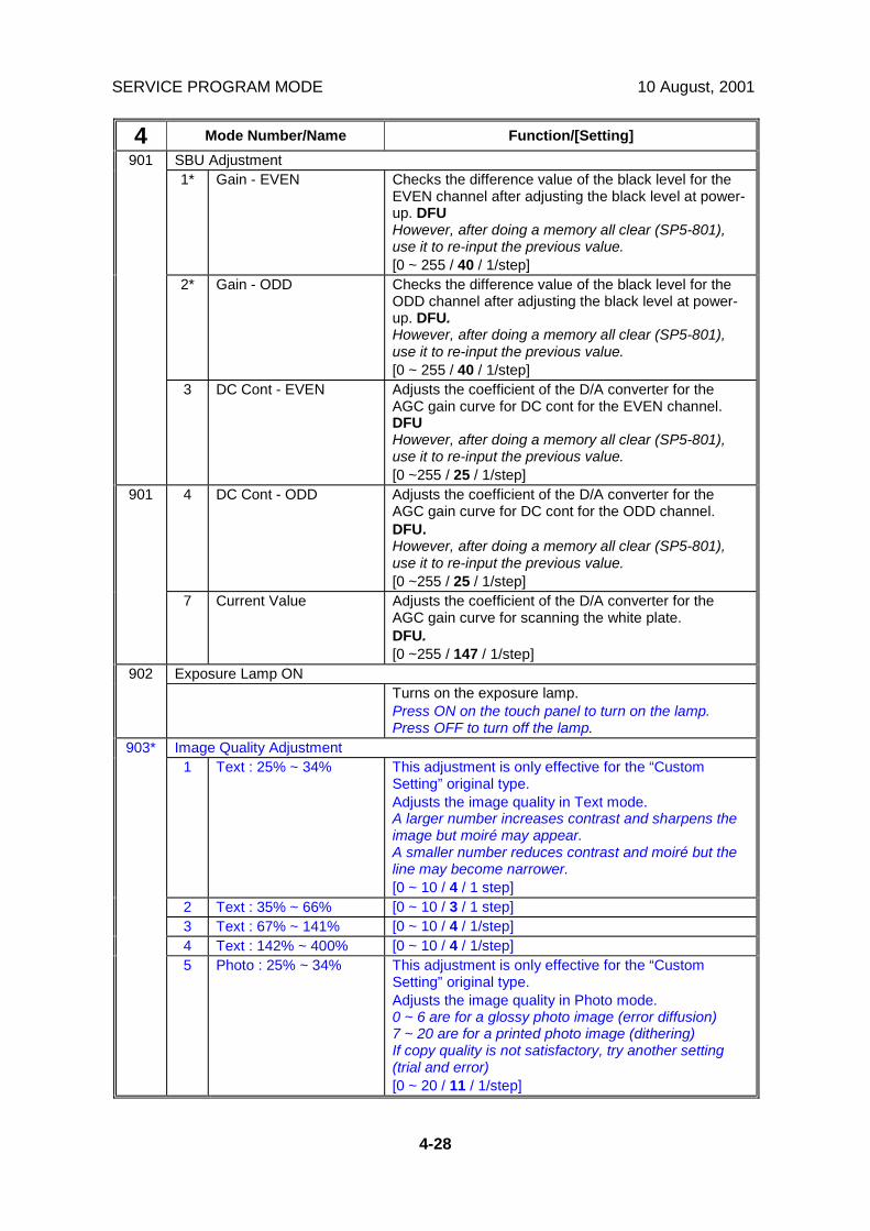
SERVICE PROGRAM MODE 10 August, 2001
4-28
4 Mode Number/Name Function/[Setting]SBU Adjustment1* Gain - EVEN Checks the difference value of the black level for the
EVEN channel after adjusting the black level at power-up. DFUHowever, after doing a memory all clear (SP5-801),use it to re-input the previous value.[0 ~ 255 / 40 / 1/step]
2* Gain - ODD Checks the difference value of the black level for theODD channel after adjusting the black level at power-up. DFU.However, after doing a memory all clear (SP5-801),use it to re-input the previous value.[0 ~ 255 / 40 / 1/step]
901
3 DC Cont - EVEN Adjusts the coefficient of the D/A converter for theAGC gain curve for DC cont for the EVEN channel.DFUHowever, after doing a memory all clear (SP5-801),use it to re-input the previous value.[0 ~255 / 25 / 1/step]
4 DC Cont - ODD Adjusts the coefficient of the D/A converter for theAGC gain curve for DC cont for the ODD channel.DFU.However, after doing a memory all clear (SP5-801),use it to re-input the previous value.[0 ~255 / 25 / 1/step]
901
7 Current Value Adjusts the coefficient of the D/A converter for theAGC gain curve for scanning the white plate.DFU.[0 ~255 / 147 / 1/step]
Exposure Lamp ON902Turns on the exposure lamp.Press ON on the touch panel to turn on the lamp.Press OFF to turn off the lamp.
Image Quality Adjustment1 Text : 25% ~ 34% This adjustment is only effective for the “Custom
Setting” original type.Adjusts the image quality in Text mode.A larger number increases contrast and sharpens theimage but moiré may appear.A smaller number reduces contrast and moiré but theline may become narrower.[0 ~ 10 / 4 / 1 step]
2 Text : 35% ~ 66% [0 ~ 10 / 3 / 1 step]3 Text : 67% ~ 141% [0 ~ 10 / 4 / 1/step]4 Text : 142% ~ 400% [0 ~ 10 / 4 / 1/step]
903*
5 Photo : 25% ~ 34% This adjustment is only effective for the “CustomSetting” original type.Adjusts the image quality in Photo mode.0 ~ 6 are for a glossy photo image (error diffusion)7 ~ 20 are for a printed photo image (dithering)If copy quality is not satisfactory, try another setting(trial and error)[0 ~ 20 / 11 / 1/step]

10 August, 2001 SERVICE PROGRAM MODE
4-29
Serv
ice
Tabl
es
4 Mode Number/Name Function/[Setting]6 Photo : 35% ~ 66% [0 ~ 20 / 11 / 1/step]7 Photo : 67% ~ 141% [0 ~ 20 / 11 / 1/step]8 Photo : 142% ~ 400% [0 ~ 20 / 11 / 1/step]9 Text/Photo :
25% ~ 34%This adjustment is only effective for the “CustomSetting” original type.Adjusts the image quality in Text/Photo mode.A larger number increases contrast and sharpens theimage but moiré may appear.A smaller number reduces contrast and moiré but theline may become narrower.[0 ~ 10 / 3 / 1 step]
10 Text/Photo :35% ~ 66%
[0 ~ 10 / 5 / 1 step]
11 Text/Photo :67% ~ 141%
[0 ~ 10 / 5 / 1 step]
12 Text/Photo :142% ~ 400%
[0 ~ 10 / 5 / 1 step]
13 Pale : 25% ~ 34% This adjustment is only effective for the “CustomSetting” original type.Adjusts the image quality in Pale mode.A larger number increase the number of gradations inlow contrast areas.[0 ~ 10 / 3 / 1 step]
14 Pale : 35% ~ 66% [0 ~ 10 / 3 / 1 step]15 Pale : 67% ~ 141% [0 ~ 10 / 3 / 1 step]16 Pale : 142% ~ 400% [0 ~ 10 / 3 / 1 step]17 Generation :
25% ~ 34%This adjustment is only effective for the “CustomSetting” original type.Adjusts the image quality in Generation mode.A larger number increases contrast and sharpens theimage but moiré may appear.A smaller number reduces contrast and moiré but theline may become narrower.[0 ~ 10 / 3 / 1 step]
18 Generation :35% ~ 66%
[0 ~ 10 / 5 / 1 step]
19 Generation :67% ~ 141%
[0 ~ 10 / 5 / 1 step]
903*
20 Generation :142% ~ 400%
[0 ~ 10 / 5 / 1 step]
Independent Dot Erase1 Text This adjustment is only effective for the “Custom
Setting” original type.With a larger SP setting, more dots are detected asindependent dots and erased. However, dots in mesh-like images may be detected as independent dotsmistakenly. If “0” is selected, independent dot erase isdisabled.[0 ~ 10 / 0 / 1 step]
2 Photo [0 ~ 10 / 0 / 1 step]3 Text/Photo [0 ~ 10 / 0 / 1 step]4 Pale [0 ~ 10 / 0 / 1 step]
904*
5 Generation [0 ~ 10 / 3 / 1 step]

SERVICE PROGRAM MODE 10 August, 2001
4-30
4 Mode Number/Name Function/[Setting]Background Erase
6 Text This adjustment is only effective for the “CustomSetting” original type.A larger number reduces dirty background. If “0” isselected, background erase is disabled.[0 ~ 255 / 0 / 1 step]
7 Photo [0 ~ 255 / 0 / 1 step]8 Text/Photo [0 ~ 255 / 0 / 1 step]9 Pale [0 ~ 255 / 0 / 1 step]10 Generation [0 ~ 255 / 0 / 1 step]
Gamma Selection11 Text This adjustment is only effective for the “Custom
Setting” original type.Selects the gamma table for each original type.[0 ~ 2 / 0 / 1/step]0: Standard gamma table1: This gamma table reduces the background of theoriginal and gives sharp characters.2: The gamma table increases the number ofgradations in high-density areas.
12 Photo [0 ~ 2 / 0 / 1/step]13 Text/Photo [0 ~ 2 / 0 / 1/step]14 Pale [0 ~ 2 / 0 / 1/step]
904*
15 Generation [0 ~ 2 / 0 / 1/step]Image Data Path905*
Selects one of the following video data outputs whichwill be used for printing. DFU[0 ~ 3 / 0 / 1 step]0: Normal1: After black level correction2: After shading correction without black levelcorrection3: Shading data
1Fax 25%, 50%Reduction
Determines whether 25% and 50% reduction isavailable in fax mode.[0 = No, 1 = Yes]
907*
2 Outline Level Japanese version only DFUIPU Image Data Path909*
Selects one of the following image data outputs, whichwill be used for printing. DFU[0 ~ 255 / 0 / 1 step]Bit 7: ShadingBit 6: Scanner gammaBit 5: Pre-filteringBit 4: MagnificationBit 3: Scanner/Printer MaskBit 2: GradationBit 1: FilteringBit 0: Printer gamma
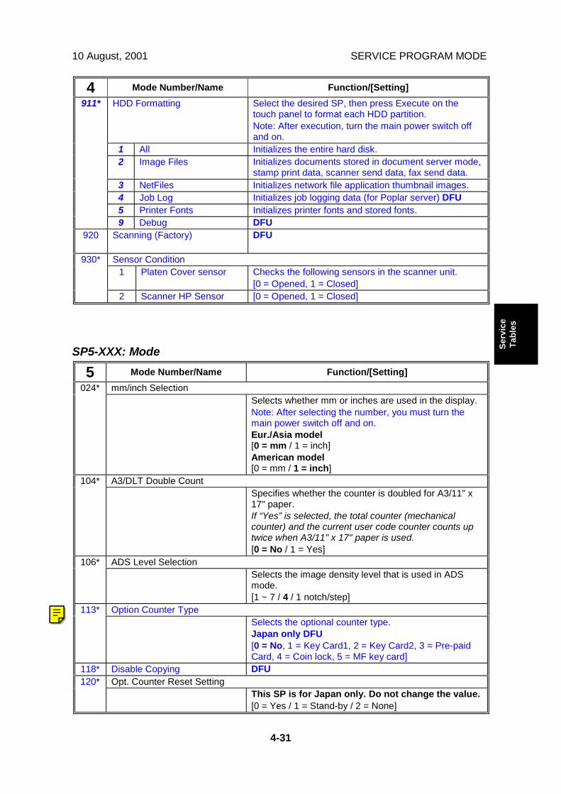
10 August, 2001 SERVICE PROGRAM MODE
4-31
Serv
ice
Tabl
es
4 Mode Number/Name Function/[Setting]HDD Formatting Select the desired SP, then press Execute on the
touch panel to format each HDD partition.Note: After execution, turn the main power switch offand on.
1 All Initializes the entire hard disk.2 Image Files Initializes documents stored in document server mode,
stamp print data, scanner send data, fax send data.3 NetFiles Initializes network file application thumbnail images.4 Job Log Initializes job logging data (for Poplar server) DFU5 Printer Fonts Initializes printer fonts and stored fonts.
911*
9 Debug DFU920 Scanning (Factory) DFU
Sensor Condition1 Platen Cover sensor Checks the following sensors in the scanner unit.
[0 = Opened, 1 = Closed]
930*
2 Scanner HP Sensor [0 = Opened, 1 = Closed]
SP5-XXX: Mode
5 Mode Number/Name Function/[Setting]mm/inch Selection024*
Selects whether mm or inches are used in the display.Note: After selecting the number, you must turn themain power switch off and on.Eur./Asia model[0 = mm / 1 = inch]American model[0 = mm / 1 = inch]
A3/DLT Double Count104*Specifies whether the counter is doubled for A3/11" x17" paper.If “Yes” is selected, the total counter (mechanicalcounter) and the current user code counter counts uptwice when A3/11" x 17" paper is used.[0 = No / 1 = Yes]
ADS Level Selection106*Selects the image density level that is used in ADSmode.[1 ~ 7 / 4 / 1 notch/step]
Option Counter Type113*Selects the optional counter type.Japan only DFU[0 = No, 1 = Key Card1, 2 = Key Card2, 3 = Pre-paidCard, 4 = Coin lock, 5 = MF key card]
118* Disable Copying DFUOpt. Counter Reset Setting120*
This SP is for Japan only. Do not change the value.[0 = Yes / 1 = Stand-by / 2 = None]
Ricoh Technical Services
RTB 19 SP 5-113: Coin lock and key card systems supported for export versions

SERVICE PROGRAM MODE 10 August, 2001
4-32
5 Mode Number/Name Function/[Setting]Key Counter Up Timing121*
Determines whether the total counter counts up atpaper feed-in or at paper exit.[0 = Feed In / 1 = Exit]
APS Mode Setting127*Selects whether APS mode is selected as the power-up default.[0 = Enable / 1 = Disabled]
F Paper Size Selection129*Selects the “F” paper size.[0 ~ 2 / 0 / 1 step]0: 8" x 13"1: 8.5" x 13"2: 8.25" x 13"
Paper Size Type Selection131*Selects the paper size (type) for both originals andcopy paper.[0~2 / DIP SW setting / 1 step]0: Japan1: North America2: EuropeAfter changing the setting, turn the copier off and on. Ifthe paper size of the archive files stored on the HDD isdifferent, abnormal copies could result. Ask thecustomer to restore the archive files.
By-Pass Long Paper Mode150*Determines whether long paper can be fed from the by-pass tray.[0 = Off, 1 = On]Normally the paper length from the by-pass tray islimited to 600 mm, but this can be extended with thisSP to 1260 mm.Note that, with either setting, the image quality can onlybe guaranteed for 432 mm.
Page Stamp3 Duplex Printout
Right/Left PositionDetermines how horizontal printing is executed duringduplex printing. Set the upper right corner of the frontside and the upper left corner of the back side so thestarting points for horizontal printing are the same onboth sides DFU.[–10~+10 / 0 / 1 mm step]–10: Extreme right+10: Extreme left
212*
4* Duplex PrintoutHigh/Low Position
Determines how vertical printing is executed duringduplex printing. Set the upper right corner of the frontside and the upper left corner of the back side so thestarting points for vertical printing are the same on bothsides. DFU[–10~+10 / 0 / 1 mm step]–10: Extreme top+10: Extreme bottom
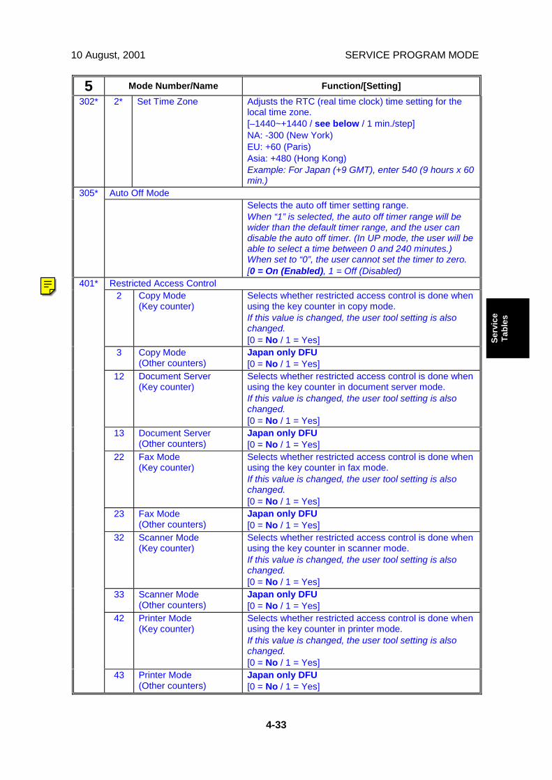
10 August, 2001 SERVICE PROGRAM MODE
4-33
Serv
ice
Tabl
es
5 Mode Number/Name Function/[Setting]302* 2* Set Time Zone Adjusts the RTC (real time clock) time setting for the
local time zone.[–1440~+1440 / see below / 1 min./step]NA: -300 (New York)EU: +60 (Paris)Asia: +480 (Hong Kong)Example: For Japan (+9 GMT), enter 540 (9 hours x 60min.)
Auto Off Mode305*Selects the auto off timer setting range.When “1” is selected, the auto off timer range will bewider than the default timer range, and the user candisable the auto off timer. (In UP mode, the user will beable to select a time between 0 and 240 minutes.)When set to “0”, the user cannot set the timer to zero.[0 = On (Enabled), 1 = Off (Disabled)
Restricted Access Control2 Copy Mode
(Key counter)Selects whether restricted access control is done whenusing the key counter in copy mode.If this value is changed, the user tool setting is alsochanged.[0 = No / 1 = Yes]
3 Copy Mode(Other counters)
Japan only DFU[0 = No / 1 = Yes]
12 Document Server(Key counter)
Selects whether restricted access control is done whenusing the key counter in document server mode.If this value is changed, the user tool setting is alsochanged.[0 = No / 1 = Yes]
13 Document Server(Other counters)
Japan only DFU[0 = No / 1 = Yes]
22 Fax Mode(Key counter)
Selects whether restricted access control is done whenusing the key counter in fax mode.If this value is changed, the user tool setting is alsochanged.[0 = No / 1 = Yes]
23 Fax Mode(Other counters)
Japan only DFU[0 = No / 1 = Yes]
32 Scanner Mode(Key counter)
Selects whether restricted access control is done whenusing the key counter in scanner mode.If this value is changed, the user tool setting is alsochanged.[0 = No / 1 = Yes]
33 Scanner Mode(Other counters)
Japan only DFU[0 = No / 1 = Yes]
42 Printer Mode(Key counter)
Selects whether restricted access control is done whenusing the key counter in printer mode.If this value is changed, the user tool setting is alsochanged.[0 = No / 1 = Yes]
401*
43 Printer Mode(Other counters)
Japan only DFU[0 = No / 1 = Yes]
Ricoh Technical Services
5-401 RTB 6: This shoould now be deleted, because it has been moved to the user tools

SERVICE PROGRAM MODE 10 August, 2001
4-34
5 Mode Number/Name Function/[Setting]PM Alarm
1 Interval Sets the PM interval.The value stored in this SP is used when the value ofSP5-501-2 is “1”.[0 ~ 255 / 0 / 1 k copies/step]
501*
2 Original Alarm Japan only. DFUSelects whether the PM alarm for the number of scansis enabled or not.If this is “1”, the PM alarm function is enabled.[0 = No / 1 = Yes]
Jam Alarm Setting504*Sets the alarm to sound for the specified jam level(document misfeeds are not included).Japan only DFU[0~3 / 3 / 1 step]0: Zero (Off)1: Low (2.5K jams)2: Medium (3K jams)3: High (6K jams)
Error Alarm Setting505*Sets the error alarm level. Japan only DFU[0~255 / 50 / 100 copies per step]
Consumable Alarm1 Paper Switches the control call on/off for the paper supply.
Japan only DFU0: Off, 1: On0: No alarm.1: Sets the alarm to sound for the specified numbertransfer sheets for each paper size (A3, A4, B4, B5,DLT, LG, LT, HLT)
2 Staple Switches the control call on/off for the stapler installedin the finisher. Japan only DFU0: Off, 1: On0: No alarm1: Alarm goes off for every 1K of staples used.
3 Toner Switches the control call on/off for the toner end.Japan only DFU0: Off, 1: OnIf you select “1” the alarm will sound when the copierdetects toner end.
128* Others132* A3133* A4134* A5141* B4142* B5160* DLT164* LG166* LT
507*
172* HLT
The “Paper Supply Call Level: nn” SPs specify thepaper control call interval for the referenced papersizes.Japan only DFU[00250 ~ 10000 / 1000 / 1 Step]

10 August, 2001 SERVICE PROGRAM MODE
4-35
Serv
ice
Tabl
es
5 Mode Number/Name Function/[Setting]CC Call
1 Remain of Jam(Unattended Jam)
Switches the control call on/off for an unattended jam.Japan only DFU0: Off, 1: OnIf you select “1”, the alarm sound if a jam is leftunattended for 15 minutes.
2 Continuous JamOccurrence
Switches the control call on/off for the occurrence ofconsecutive jams. Japan only DFU0: Off, 1: OnIf you select “1”, the alarm will sound if 5 consecutivejams occur in the copier.
3 Continuous Door Open Switches the control call on/off for the cover openalarm. Japan only DFU0: Off, 1: OnIf you select “1”, the alarm will sound if the doorremains open for 15 minutes.
4 New CC Call Mode Selects whether or not the new CC call.Japan only DFU0: Previous Mode, 1: New Mode
11 Time for Remain ofJam
This SP is effective when the value of SP5-508-4 is “1”.Japan only DFU[3 ~ 30 / 10 / 1 min/step]
12 Number of continuosJam
This SP is effective when the value of SP5-508-4 is “1”.Japan only DFU[2 ~ 10 / 5 / 1 time/step]
13 Time of ContinuousDoor Open
This SP is effective when the value of SP5-508-4 is “1”.Japan only DFU[3 ~ 30 / 10 / 1 min/step]
21 Remain of Jam Mode(Unattended Jam)
This SP is effective when the value of SP5-508-4 is “1”.Japan only DFU0: Auto Call, 1: Alarm
22 Continuous JamOccurrence Mode
This SP is effective when the value of SP5-508-4 is “1”.Japan only DFU0: Auto Call, 1: Alarm
508*
23 Continuous Door OpenMode
This SP is effective when the value of SP5-508-4 is “1”.Japan only DFU0: Auto Call, 1: Alarm
Memory All Clear Resets all correction data for process control and allsoftware counters, and returns all modes andadjustments to their default values. (☛ 4.2.7).To execute, hold down # for over 3 seconds, and thenturn the copier off and on again.Use this SP only after replacing the NVRAM, or afterthe copier has malfunctioned due to a damagedNVRAM.
1 All modules Initializes items 2 ~ 12 below.2 Engine Initializes all registration settings for the engine and
processing settings.
801
3 SCS (System ControlService)/SRAM
Initializes default system settings, CSS settings,operation display coordinates, and ROM updateinformation.SCS: System Control Service
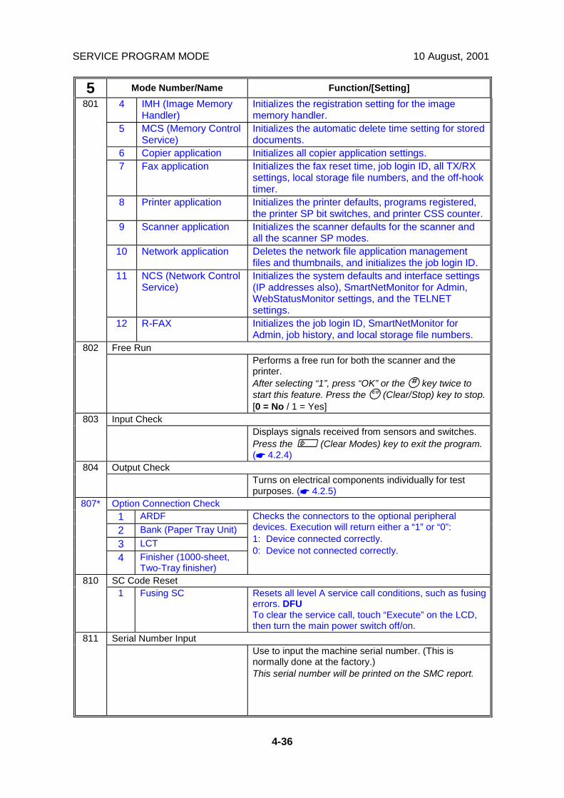
SERVICE PROGRAM MODE 10 August, 2001
4-36
5 Mode Number/Name Function/[Setting]4 IMH (Image Memory
Handler)Initializes the registration setting for the imagememory handler.
5 MCS (Memory ControlService)
Initializes the automatic delete time setting for storeddocuments.
6 Copier application Initializes all copier application settings.7 Fax application Initializes the fax reset time, job login ID, all TX/RX
settings, local storage file numbers, and the off-hooktimer.
8 Printer application Initializes the printer defaults, programs registered,the printer SP bit switches, and printer CSS counter.
9 Scanner application Initializes the scanner defaults for the scanner andall the scanner SP modes.
10 Network application Deletes the network file application managementfiles and thumbnails, and initializes the job login ID.
11 NCS (Network ControlService)
Initializes the system defaults and interface settings(IP addresses also), SmartNetMonitor for Admin,WebStatusMonitor settings, and the TELNETsettings.
801
12 R-FAX Initializes the job login ID, SmartNetMonitor forAdmin, job history, and local storage file numbers.
Free Run802Performs a free run for both the scanner and theprinter.After selecting “1”, press “OK” or the ' key twice tostart this feature. Press the & (Clear/Stop) key to stop.[0 = No / 1 = Yes]
Input Check803Displays signals received from sensors and switches.Press the " (Clear Modes) key to exit the program.(☛ 4.2.4)
Output Check804Turns on electrical components individually for testpurposes. (☛ 4.2.5)
Option Connection Check1 ARDF2 Bank (Paper Tray Unit)3 LCT
807*
4 Finisher (1000-sheet,Two-Tray finisher)
Checks the connectors to the optional peripheraldevices. Execution will return either a “1” or “0”:1: Device connected correctly.0: Device not connected correctly.
SC Code Reset8101 Fusing SC Resets all level A service call conditions, such as fusing
errors. DFUTo clear the service call, touch “Execute” on the LCD,then turn the main power switch off/on.
Serial Number Input811Use to input the machine serial number. (This isnormally done at the factory.)This serial number will be printed on the SMC report.
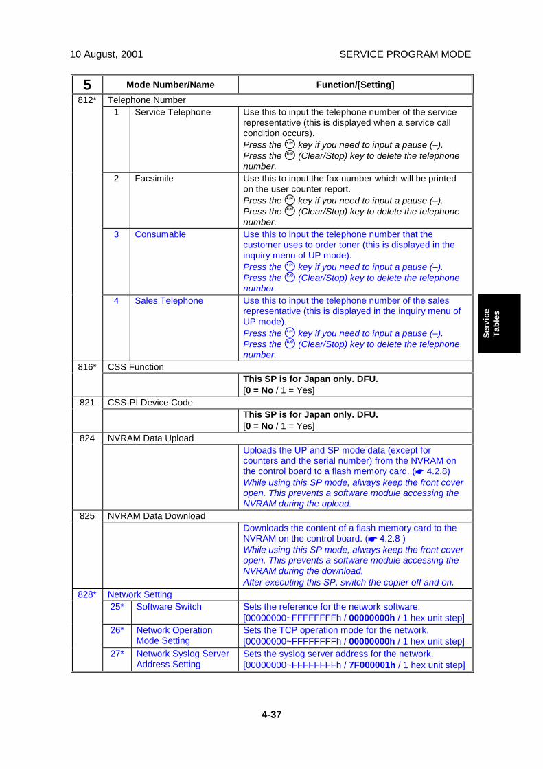
10 August, 2001 SERVICE PROGRAM MODE
4-37
Serv
ice
Tabl
es
5 Mode Number/Name Function/[Setting]Telephone Number
1 Service Telephone Use this to input the telephone number of the servicerepresentative (this is displayed when a service callcondition occurs).Press the ! key if you need to input a pause (–).Press the & (Clear/Stop) key to delete the telephonenumber.
2 Facsimile Use this to input the fax number which will be printedon the user counter report.Press the ! key if you need to input a pause (–).Press the & (Clear/Stop) key to delete the telephonenumber.
3 Consumable Use this to input the telephone number that thecustomer uses to order toner (this is displayed in theinquiry menu of UP mode).Press the ! key if you need to input a pause (–).Press the & (Clear/Stop) key to delete the telephonenumber.
812*
4 Sales Telephone Use this to input the telephone number of the salesrepresentative (this is displayed in the inquiry menu ofUP mode).Press the ! key if you need to input a pause (–).Press the & (Clear/Stop) key to delete the telephonenumber.
CSS Function816*This SP is for Japan only. DFU.[0 = No / 1 = Yes]
CSS-PI Device Code821This SP is for Japan only. DFU.[0 = No / 1 = Yes]
NVRAM Data Upload824Uploads the UP and SP mode data (except forcounters and the serial number) from the NVRAM onthe control board to a flash memory card. (☛ 4.2.8)While using this SP mode, always keep the front coveropen. This prevents a software module accessing theNVRAM during the upload.
NVRAM Data Download825Downloads the content of a flash memory card to theNVRAM on the control board. (☛ 4.2.8 )While using this SP mode, always keep the front coveropen. This prevents a software module accessing theNVRAM during the download.After executing this SP, switch the copier off and on.
Network Setting25* Software Switch Sets the reference for the network software.
[00000000~FFFFFFFFh / 00000000h / 1 hex unit step]26* Network Operation
Mode SettingSets the TCP operation mode for the network.[00000000~FFFFFFFFh / 00000000h / 1 hex unit step]
828*
27* Network Syslog ServerAddress Setting
Sets the syslog server address for the network.[00000000~FFFFFFFFh / 7F000001h / 1 hex unit step]
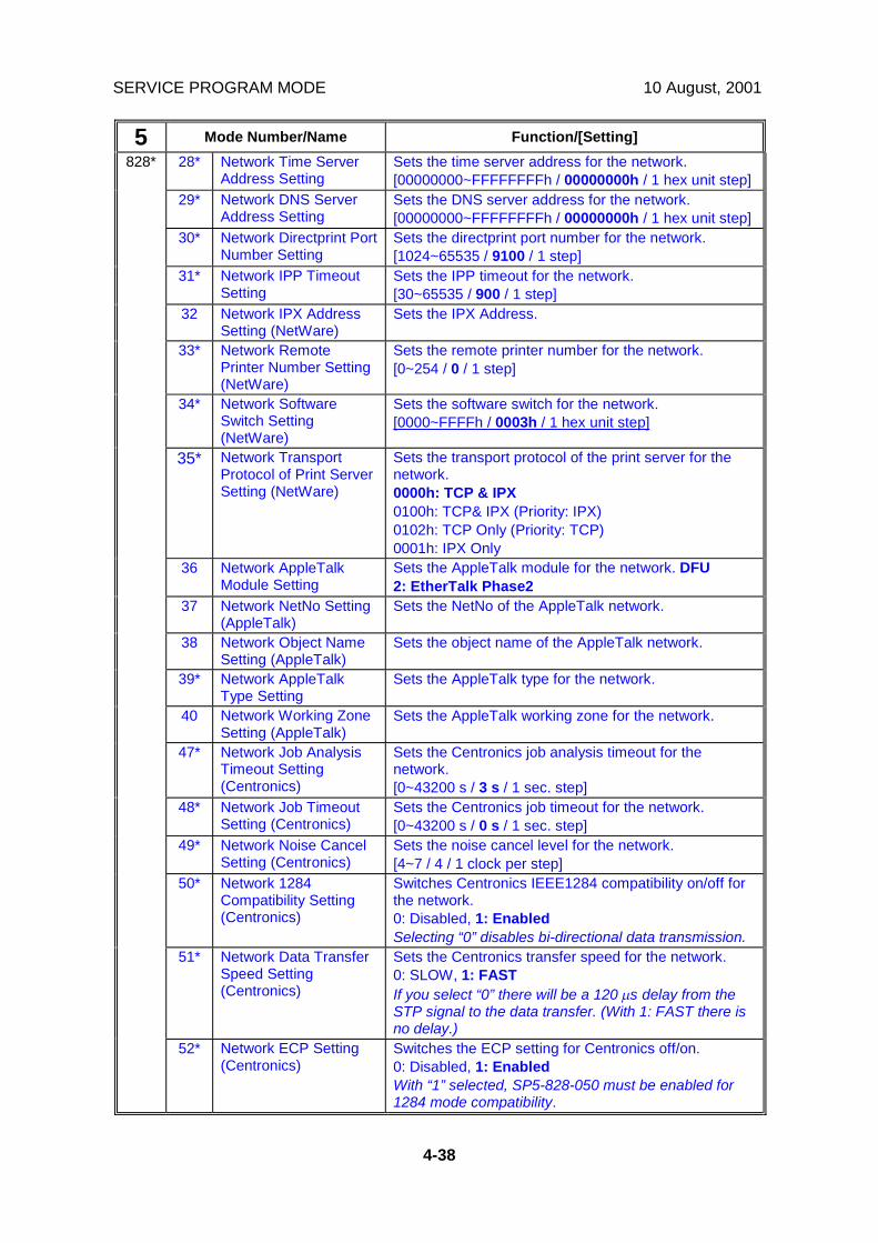
SERVICE PROGRAM MODE 10 August, 2001
4-38
5 Mode Number/Name Function/[Setting]28* Network Time Server
Address SettingSets the time server address for the network.[00000000~FFFFFFFFh / 00000000h / 1 hex unit step]
29* Network DNS ServerAddress Setting
Sets the DNS server address for the network.[00000000~FFFFFFFFh / 00000000h / 1 hex unit step]
30* Network Directprint PortNumber Setting
Sets the directprint port number for the network.[1024~65535 / 9100 / 1 step]
31* Network IPP TimeoutSetting
Sets the IPP timeout for the network.[30~65535 / 900 / 1 step]
32 Network IPX AddressSetting (NetWare)
Sets the IPX Address.
33* Network RemotePrinter Number Setting(NetWare)
Sets the remote printer number for the network.[0~254 / 0 / 1 step]
34* Network SoftwareSwitch Setting(NetWare)
Sets the software switch for the network.[0000~FFFFh / 0003h / 1 hex unit step]
35* Network TransportProtocol of Print ServerSetting (NetWare)
Sets the transport protocol of the print server for thenetwork.0000h: TCP & IPX0100h: TCP& IPX (Priority: IPX)0102h: TCP Only (Priority: TCP)0001h: IPX Only
36 Network AppleTalkModule Setting
Sets the AppleTalk module for the network. DFU2: EtherTalk Phase2
37 Network NetNo Setting(AppleTalk)
Sets the NetNo of the AppleTalk network.
38 Network Object NameSetting (AppleTalk)
Sets the object name of the AppleTalk network.
39* Network AppleTalkType Setting
Sets the AppleTalk type for the network.
40 Network Working ZoneSetting (AppleTalk)
Sets the AppleTalk working zone for the network.
47* Network Job AnalysisTimeout Setting(Centronics)
Sets the Centronics job analysis timeout for thenetwork.[0~43200 s / 3 s / 1 sec. step]
48* Network Job TimeoutSetting (Centronics)
Sets the Centronics job timeout for the network.[0~43200 s / 0 s / 1 sec. step]
49* Network Noise CancelSetting (Centronics)
Sets the noise cancel level for the network.[4~7 / 4 / 1 clock per step]
50* Network 1284Compatibility Setting(Centronics)
Switches Centronics IEEE1284 compatibility on/off forthe network.0: Disabled, 1: EnabledSelecting “0” disables bi-directional data transmission.
51* Network Data TransferSpeed Setting(Centronics)
Sets the Centronics transfer speed for the network.0: SLOW, 1: FASTIf you select “0” there will be a 120 µs delay from theSTP signal to the data transfer. (With 1: FAST there isno delay.)
828*
52* Network ECP Setting(Centronics)
Switches the ECP setting for Centronics off/on.0: Disabled, 1: EnabledWith “1” selected, SP5-828-050 must be enabled for1284 mode compatibility.
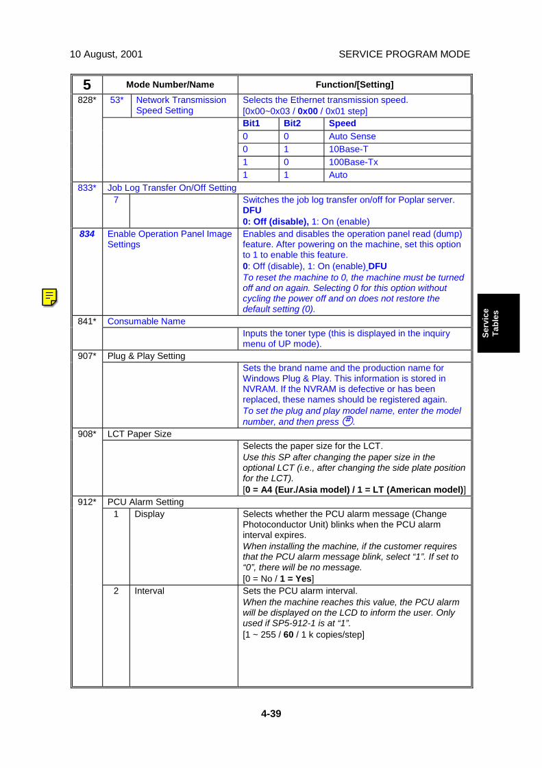
10 August, 2001 SERVICE PROGRAM MODE
4-39
Serv
ice
Tabl
es
5 Mode Number/Name Function/[Setting]53* Network Transmission
Speed SettingSelects the Ethernet transmission speed.[0x00~0x03 / 0x00 / 0x01 step]Bit1 Bit2 Speed0 0 Auto Sense0 1 10Base-T1 0 100Base-Tx
828*
1 1 AutoJob Log Transfer On/Off Setting833*
7 Switches the job log transfer on/off for Poplar server.DFU0: Off (disable), 1: On (enable)
834 Enable Operation Panel ImageSettings
Enables and disables the operation panel read (dump)feature. After powering on the machine, set this optionto 1 to enable this feature.0: Off (disable), 1: On (enable) DFUTo reset the machine to 0, the machine must be turnedoff and on again. Selecting 0 for this option withoutcycling the power off and on does not restore thedefault setting (0).
Consumable Name841*Inputs the toner type (this is displayed in the inquirymenu of UP mode).
Plug & Play Setting907*Sets the brand name and the production name forWindows Plug & Play. This information is stored inNVRAM. If the NVRAM is defective or has beenreplaced, these names should be registered again.To set the plug and play model name, enter the modelnumber, and then press '.
LCT Paper Size908*Selects the paper size for the LCT.Use this SP after changing the paper size in theoptional LCT (i.e., after changing the side plate positionfor the LCT).[0 = A4 (Eur./Asia model) / 1 = LT (American model)]
PCU Alarm Setting1 Display Selects whether the PCU alarm message (Change
Photoconductor Unit) blinks when the PCU alarminterval expires.When installing the machine, if the customer requiresthat the PCU alarm message blink, select “1”. If set to“0”, there will be no message.[0 = No / 1 = Yes]
912*
2 Interval Sets the PCU alarm interval.When the machine reaches this value, the PCU alarmwill be displayed on the LCD to inform the user. Onlyused if SP5-912-1 is at “1”.[1 ~ 255 / 60 / 1 k copies/step]
Ricoh Technical Services
RTB 4, 6 SP 5836 added (settings for the Capture function)
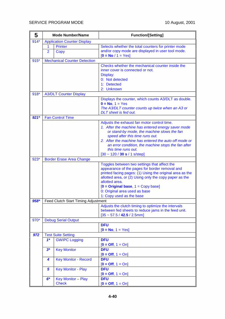
SERVICE PROGRAM MODE 10 August, 2001
4-40
5 Mode Number/Name Function/[Setting]Application Counter Display
1 Printer914*
2 CopySelects whether the total counters for printer modeand/or copy mode are displayed in user tool mode.[0 = No / 1 = Yes]
Mechanical Counter Detection915*Checks whether the mechanical counter inside theinner cover is connected or not.Display:0: Not detected1: Detected2: Unknown
A3/DLT Counter Display918*Displays the counter, which counts A3/DLT as double.0 = No, 1 = YesThe A3/DLT counter counts up twice when an A3 orDLT sheet is fed out.
Fan Control Time921*Adjusts the exhaust fan motor control time.1. After the machine has entered energy saver mode
or stand-by mode, the machine slows the fanspeed after this time runs out.
2. After the machine has entered the auto off mode oran error condition, the machine stops the fan afterthis time runs out.
[30 ~ 120 / 30 s / 1 s/step]Border Erase Area Change923*
Toggles between two settings that affect theappearance of the pages for border removal andprinted facing pages: (1) Using the original area as theallotted area, or (2) Using only the copy paper as theallotted area.[0 = Original base, 1 = Copy base]0: Original area used as base1: Copy used as the base
Feed Clutch Start Timing Adjustment958*Adjusts the clutch timing to optimize the intervalsbetween fed sheets to reduce jams in the feed unit.[35 ~ 57.5 / 42.5 / 2.5mm]
Debug Serial Output970*DFU[0 = No, 1 = Yes]
Test Suite Setting1* GWIPC Logging DFU
[0 = Off, 1 = On]3* Key Monitor DFU
[0 = Off, 1 = On]4 Key Monitor - Record DFU
[0 = Off, 1 = On]5 Key Monitor - Play DFU
[0 = Off, 1 = On]
972
6* Key Monitor – PlayCheck
DFU[0 = Off, 1 = On]

10 August, 2001 SERVICE PROGRAM MODE
4-41
Serv
ice
Tabl
es
5 Mode Number/Name Function/[Setting]7* Key Monitor – Min.
TimeDFU[0 ~ 255 / 0 / 0.1 s/step]
8* Key Monitor – MaxTime
DFU[0 ~ 255 / 100 / 0.1 s/step]
9 Key Monitor – PlaySpeed
DFU[0.01 ~ 100 / 100 / 0.01 s/step]
10 Key Monitor – RepeatTime
DFU[1 ~ 65535 / 1 / 1 step]
11 Key Monitor – Log No. DFU12 Key Monitor – Play File
No.DFU
972
13 Key Monitor File No. DFUCherry Server Selection974*
Switches writing between the Scan Router V2 Liteapplication provided and the optional full version.0: Lite, 1: Full
SMC Printing1 All (Data List)2 SP (Mode Data List)3 User Program4 Logging Data5 Diagnosis Report7 NIB Summary21 Copier User Program22 Scanner SP
990
23 Scanner User Program
Prints all of the system parameter lists for the itemselected. (☛ 4.2.6) Input the number for the item thatyou want to print, then press “Execute” on the touchpanel.
SP6-XXX: Peripherals
6 Mode Number/Name Function/[Setting]ADF Registration
1 Side-to-Side Adjusts the registration in ADF mode.Use the ! key to toggle between + and - beforeentering the value. See “Replacement and Adjustment- Copy Adjustment” for details.[–5.0 ~ +5.0 / 0.0 / 0.1 mm/step]
2 Leading Edge [–5.0 ~ +5.0 / 0.0 / 0.1 mm/step]3 Trailing Edge Erase Adjusts the trailing edge erase margin in ADF mode.
Use the ! key to toggle between + and - beforeentering the value. See “Replacement and Adjustment- Copy Adjustment” for details.[–5.0 ~ +5.0 / –1.0 / 0.1 mm/step]
006*
4 Side-to-Side/Rear Adjusts the side-to-side registration on the rear side ofthe original in ADF mode.Use the ! key to toggle between + and - beforeentering the value. See “Replacement and Adjustment- Copy Adjustment” for details.[–5.0 ~ +5.0 / 0.0 / 0.1 mm/step]

SERVICE PROGRAM MODE 10 August, 2001
4-42
6 Mode Number/Name Function/[Setting]5 Sub Scan Magnification Adjusts the sub scan magnification in ADF mode.
Use the ! key to toggle between + and - beforeentering the value. See “Replacement and Adjustment- Copy Adjustment” for details.[–5.0 ~ +5.0 / 0.0 / 0.1 % step]
6 Skew Correction Selects whether or not skew correction is done in ADFmode.0 = Off, 1 = On
006*
7 Original BuckleAdjustment
Adjusts the amount of original buckle at the ARDFregistration roller when the ARDF feeds the rear sideof the original.This SP is effective only when SP6-006-6 is at “1”.Use the ! key to toggle between + and - beforeentering the value. See “Replacement and Adjustment- Copy Adjustment” for details.[–5.0 ~ +5.0 / 0.0 / 0.1 mm/step]
ADF Input Check007Displays the signals received from sensors andswitches of the ARDF.( ☛ 4.2.4)
ADF Output Check008Switches on each electrical component (ARDF motor,solenoid, etc.) of the ARDF for testing. (☛ 4.2.5)Press # to switch on or $ to switch off.
ADF Free Run009Performs an ARDF free run in duplex mode. Press #to start.1: To Start, 0: To cancelThis is a general free run controlled from the copier.For more detailed free run modes, see the ARDFmanual.
Stamp Position Adjustment010*Adjusts the stamp position in the sub-scan direction infax mode.[–5.0 ~ +5.0 / 0 / 1 mm/step]
ADF Original Size Detection016*Selects whether the machine determines that theoriginal is A4/LT, or 8K/16K when the APS sensor inthe ADF does not detect the original size.8K/16K is not available for 115V machines.[0 = Normal (LT for USA models, A4 for Europe/Asiamodels)1 = Reversed [A4 for USA models, LT for Europe/Asiamodels]2 = 8K/16K]
Finisher Input Check117Displays the signals received from sensors andswitches in the finisher. ( ☛ 4.2.4)
Finisher Output Check118Switches on each electrical component of the finisherfor testing. (☛ 4.2.5)Press # to switch on or $ to switch off.

10 August, 2001 SERVICE PROGRAM MODE
4-43
Serv
ice
Tabl
es
6 Mode Number/Name Function/[Setting]ADF APS Data Display901
Displays the status of the original size sensors in theADF. (☛ 4.2.10)
ADF Shading Interval Time910*Adjusts the interval for shading processing in DFmode.Light and heat may affect the scanner response. Ifcopy quality indicates that white level is drifting duringa DF copy job, reduce this setting.[0 ~ 120 / 20s / 1s/step]
ADF Loop Back Test1 DF GATE DFU
0 = Gate, 1 = Asart2 DF TXD Break DFU
0 = Off, 1 = On3 Serial Communication DFU
0 = NG, 1 = OK4 Original Set DFU
0 = Off, 1 = On
920
5 Serial Check DFUFinisher/Duplex loop Back Test
1 Loop Back Test DFU
925
2 Result DFU
SP7-XXX: Data Log
7 Mode Number/Name Function/[Setting]Main Motor Operation Time001*
The number of prints and drive time for drumrevolutions can be obtained by counting the mainmotor revolution time. If the amount of the timerequired for the drum to revolve to print 1 copyincreases, this data combined with the number ofcopies can be used to analyze problems and could beuseful for future product development.Display: 00000000~99999999 min.
Total Original Counter1 All Modes2 Copier3 Fax4 Document Box5 Scanner
002*
6 Others
Select a number to display the total original count(number of originals fed) for the selected item.
Total Print Counter1 All Modes2 Copier
003*
3 Fax
Select a number to display the total print count for theselected item.

SERVICE PROGRAM MODE 10 August, 2001
4-44
7 Mode Number/Name Function/[Setting]4 Printer003*5 Others
Select a number to display the total print count for theselected item.
C/O, P/O Counters1 C/O Counter
006*
2 P/O CounterDisplays the number of copies per original whenmaking more than 10 copies.For example, if you make 15 copies of a 3 pageoriginal document, for a total of 45 sheets, then thecounter would be 15 (5 copies counted from 11 to 15 x3 originals). No count will be returned for 1~10 copiesof an original.
Other Counter1 Duplex Counter2 A3/DLT Counter3 Staple Counter
007*
4 Scan Counter
Displays the count total for the selected item.
Copy Counter - Paper Size5 A4 H (Sideways)6 A5 H (Sideways)14 B5 H (Sideways)38 LT H (Sideways)44 HLT H (Sideways)132 A3 V (Lengthwise)133 A4 V (Lengthwise)134 A5 V (Lengthwise)141 B4 V (Lengthwise)142 B5 V (Lengthwise)160 DLT V (Lengthwise)164 LG V (Lengthwise)166 LT V (Lengthwise)172 HLT V (Lengthwise)
101*
255 Others
Displays the total number of copies by paper size.
Total Scan Counter201*Displays the total number of scanned originals.
Copy Counter - Paper Tray1 1st2 2nd3 3rd4 4th5 LCT
204*
6 By-pass
Displays the total number of copies fed from eachpaper feed station.
Total ADF Counter205*Displays the total number of originals fed by the ADF.
Staple Counter1 Normal Display the total number of staples fired.
206*
2 Booklet DFUPunch Counter209*
Displays the total times the punch has fired. DFU

10 August, 2001 SERVICE PROGRAM MODE
4-45
Serv
ice
Tabl
es
7 Mode Number/Name Function/[Setting]Copy Counter - Mag.
1 25% ~ 49%2 50% ~ 99%3 Full Size4 101% ~ 200%5 201% ~ 400%6 Direct Mag.7 Direct Size Mag.
301*
8 Auto Reduce/Enlarge
Displays the total number of copies by reproductionratio and magnification.
Copy Counter - Copy Mode1 Text Mode2 Text/Photo Mode3 Photo Mode4 Generation Mode5 Pale Mode6 Punch7 Repeat8 Sort9 Staple10 Series11 Erase12 Duplex13 ADF14 Double Copy15 Duplex Original16 Interrupt Copy17 Combine 1 Side18 Combine 2 Side19 Booklet20 Magazine21 Batch22 SADF23 Mixed Sizes24 Stamp25 Cover Page/Chapter
Page
304*
26 Slip Sheet
Displays the total number of copies by copy mode.
Copy Counter – Set Number1 1 to 12 1 to 2~53 1 to 6~104 1 to 11~205 1 to 21~506 1 to 51~1007 1 to 101~300
305*
8 1 to 301~ Over
Displays the total number of prints for multiple copyjobs.
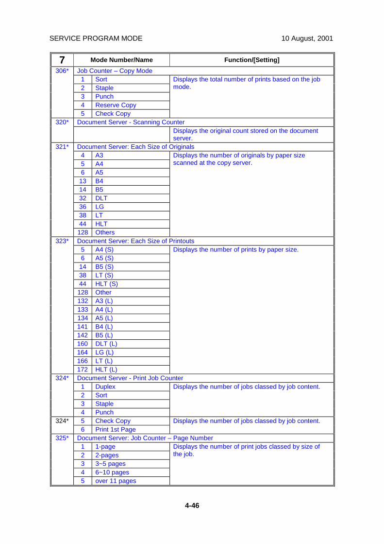
SERVICE PROGRAM MODE 10 August, 2001
4-46
7 Mode Number/Name Function/[Setting]Job Counter – Copy Mode
1 Sort2 Staple3 Punch4 Reserve Copy
306*
5 Check Copy
Displays the total number of prints based on the jobmode.
Document Server - Scanning Counter320*Displays the original count stored on the documentserver.
Document Server: Each Size of Originals4 A35 A46 A513 B414 B532 DLT36 LG38 LT44 HLT
321*
128 Others
Displays the number of originals by paper sizescanned at the copy server.
Document Server: Each Size of Printouts5 A4 (S)6 A5 (S)14 B5 (S)38 LT (S)44 HLT (S)128 Other132 A3 (L)133 A4 (L)134 A5 (L)141 B4 (L)142 B5 (L)160 DLT (L)164 LG (L)166 LT (L)
323*
172 HLT (L)
Displays the number of prints by paper size.
Document Server - Print Job Counter1 Duplex2 Sort3 Staple
324*
4 Punch
Displays the number of jobs classed by job content.
5 Check Copy324*6 Print 1st Page
Displays the number of jobs classed by job content.
Document Server: Job Counter – Page Number1 1-page2 2-pages3 3~5 pages4 6~10 pages
325*
5 over 11 pages
Displays the number of print jobs classed by size ofthe job.

10 August, 2001 SERVICE PROGRAM MODE
4-47
Serv
ice
Tabl
es
7 Mode Number/Name Function/[Setting]Document Server: Job Counter – File Number
1 1 file2 2~5 files3 6~10 files
326*
4 over 11 files
Displays the number of print jobs classed by thenumber of files.
Document Server: Job Counter – Set Number1 1 to 12 1 to 2~53 1 to 6~104 1 to 11~205 1 to 21~506 1 to 51~1007 1 to 101~300
327*
8 1 to 301~ over
Displays the number of print jobs classed by the setsizes.
Document Server: Print Counter – Print Mode6 Punch8 Sort9 Staple12 Duplex19 Booklet20 Magazine24 Stamp25 Cover/Chapter Page
328*
26 Slip Sheet
Displays the number of prints by mode.
Total SC Counter401*Displays the total number of service calls that haveoccurred.
SC History1 Latest2 Latest 13 Latest 24 Latest 35 Latest 46 Latest 57 Latest 68 Latest 79 Latest 8
403*
10 Latest 9
Displays the most recent 10 service calls.
Total Paper Jam Counter502*Displays the total number of paper jams.
Total Original Jam Counter503*Displays the total number of original jams.

SERVICE PROGRAM MODE 10 August, 2001
4-48
7 Mode Number/Name Function/[Setting]Total Jams by LocationPaper LateError No.
Paper LagError No.
Displays the total number of paper jams by location.A “Paper Late” error occurs when the paper fails toactivate the sensor at the precise time. A “Paper Lag”paper jam occurs when the paper remains at thesensor for longer than the prescribed time.
1 At power on3 Upper relay sensor4 Lower relay sensor5 Vertical transport sensor (optional bank)6 Relay sensor (optional LCT)11 Registration sensor12 62 Paper exit sensor13 63 Bridge relay sensor14 64 Bridge exit sensor15 65 Duplex entrance sensor16 66 Duplex exit sensor17 67 1 bin tray exit sensor
20 Finisher entrance sensor21 Finisher shift tray exit sensor23 Finisher staple tray paper sensor24 Finisher stack feed-out belt HP sensor
By error26 Finisher paper taking out27 Finisher drive error28 Finisher tray lift error29 Finisher jogger drive error30 Finisher tray shift drive error31 Finisher stapler error32 Finisher stack-feed out error33 Finisher feed out error
504*
34 Finisher no response
Total Original Jam by LocationDisplays the total number of original jams by location.These jams occur when the original does not activatethe sensors.A “Paper Late” error occurs when the paper fails toactivate the sensor at the precise time. A “Paper Lag”paper jam occurs when the paper remains at thesensor for longer than the prescribed time.
1 At power onPaper LateError No.
Paper LagError No.
5 55 Registration Sensor6 56 Relay Sensor
505*
7 57 Inverter Sensor
Ricoh Technical Services
RTB 22 Changes to SP 7-504
Ricoh Technical Services
RTB 22 Changes to SP 7-505
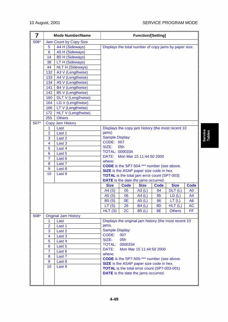
10 August, 2001 SERVICE PROGRAM MODE
4-49
Serv
ice
Tabl
es
7 Mode Number/Name Function/[Setting]Jam Count by Copy Size
5 A4 H (Sideways)6 A5 H (Sideways)14 B5 H (Sideways)38 LT H (Sideways)44 HLT H (Sideways)132 A3 V (Lengthwise)133 A4 V (Lengthwise)134 A5 V (Lengthwise)141 B4 V (Lengthwise)142 B5 V (Lengthwise)160 DLT V (Lengthwise)164 LG V (Lengthwise)166 LT V (Lengthwise)172 HLT V (Lengthwise)
506*
255 Others
Displays the total number of copy jams by paper size.
Copy Jam History1 Last2 Last 13 Last 24 Last 35 Last 46 Last 57 Last 68 Last 79 Last 810 Last 9
Displays the copy jam history (the most recent 10jams)Sample Display:CODE: 007SIZE: 05hTOTAL: 0000334DATE: Mon Mar 15 11:44:50 2000where:CODE is the SP7-504-*** number (see above.SIZE is the ASAP paper size code in hex.TOTAL is the total jam error count (SP7-003)DATE is the date the jams occurred.
Size Code Size Code Size CodeA4 (S) 05 A3 (L) 84 DLT (L) A0A5 (S) 06 A4 (L) 85 LG (L) A4B5 (S) 0E A5 (L) 86 LT (L) A6LT (S) 26 B4 (L) 8D HLT (L) AC
507*
HLT (S) 2C B5 (L) 8E Others FFOriginal Jam History
1 Last2 Last 13 Last 24 Last 35 Last 46 Last 57 Last 68 Last 79 Last 8
508*
10 Last 9
Displays the original jam history (the most recent 10jams.Sample Display:CODE: 007SIZE: 05hTOTAL: 0000334DATE: Mon Mar 15 11:44:50 2000where:CODE is the SP7-505-*** number (see above.SIZE is the ASAP paper size code in hex.TOTAL is the total error count (SP7-003-001)DATE is the date the jams occurred.
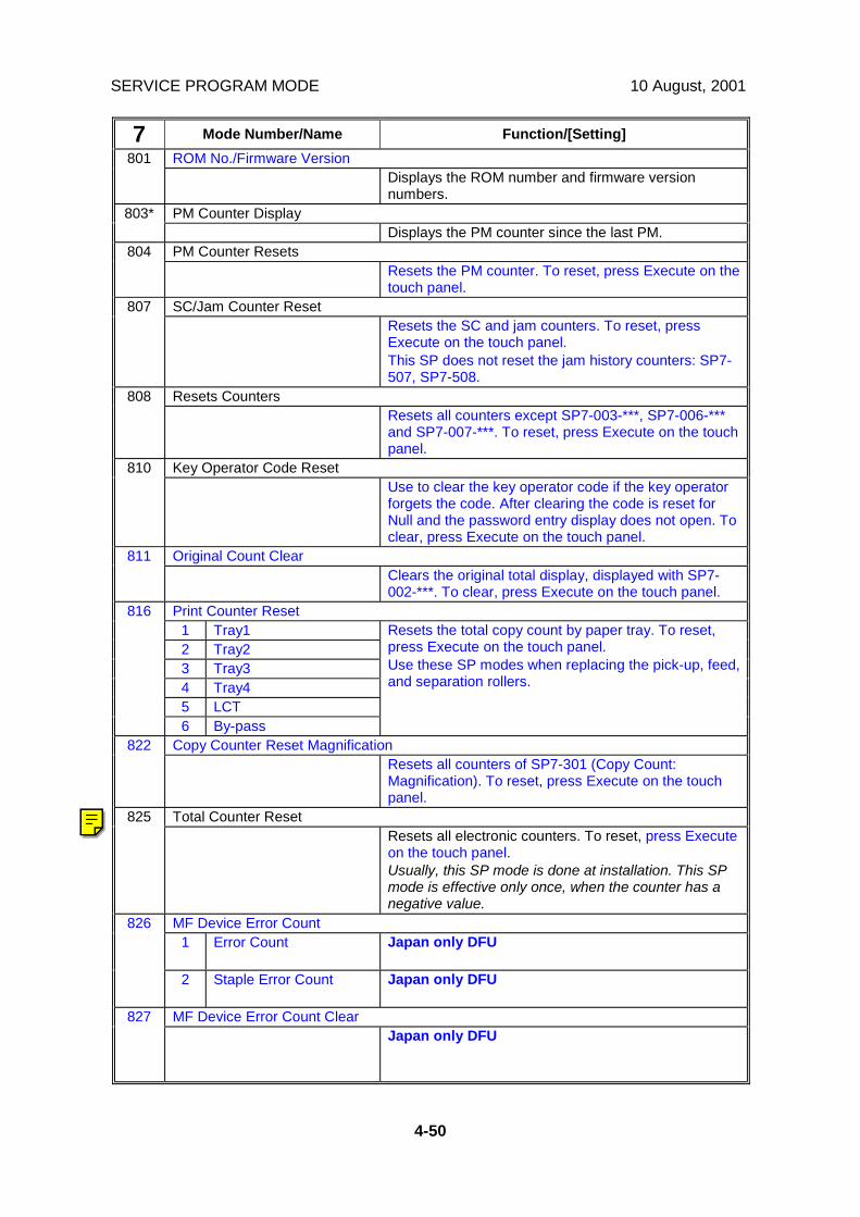
SERVICE PROGRAM MODE 10 August, 2001
4-50
7 Mode Number/Name Function/[Setting]ROM No./Firmware Version801
Displays the ROM number and firmware versionnumbers.
PM Counter Display803*Displays the PM counter since the last PM.
PM Counter Resets804Resets the PM counter. To reset, press Execute on thetouch panel.
SC/Jam Counter Reset807Resets the SC and jam counters. To reset, pressExecute on the touch panel.This SP does not reset the jam history counters: SP7-507, SP7-508.
Resets Counters808Resets all counters except SP7-003-***, SP7-006-***and SP7-007-***. To reset, press Execute on the touchpanel.
Key Operator Code Reset810Use to clear the key operator code if the key operatorforgets the code. After clearing the code is reset forNull and the password entry display does not open. Toclear, press Execute on the touch panel.
Original Count Clear811Clears the original total display, displayed with SP7-002-***. To clear, press Execute on the touch panel.
Print Counter Reset1 Tray12 Tray23 Tray34 Tray45 LCT
816
6 By-pass
Resets the total copy count by paper tray. To reset,press Execute on the touch panel.Use these SP modes when replacing the pick-up, feed,and separation rollers.
Copy Counter Reset Magnification822Resets all counters of SP7-301 (Copy Count:Magnification). To reset, press Execute on the touchpanel.
Total Counter Reset825Resets all electronic counters. To reset, press Executeon the touch panel.Usually, this SP mode is done at installation. This SPmode is effective only once, when the counter has anegative value.
MF Device Error Count1 Error Count Japan only DFU
826
2 Staple Error Count Japan only DFU
MF Device Error Count Clear827Japan only DFU
Ricoh Technical Services
General RTB 13 SP 7-825: Method of use changed
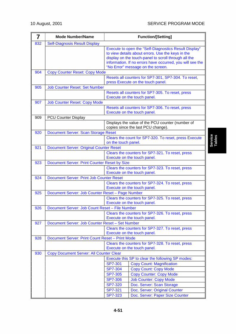
10 August, 2001 SERVICE PROGRAM MODE
4-51
Serv
ice
Tabl
es
7 Mode Number/Name Function/[Setting]Self-Diagnosis Result Display832
Execute to open the “Self-Diagnostics Result Display”to view details about errors. Use the keys in thedisplay on the touch-panel to scroll through all theinformation. If no errors have occurred, you will see the“No Error” message on the screen.
Copy Counter Reset: Copy Mode904Resets all counters for SP7-301, SP7-304. To reset,press Execute on the touch panel.
Job Counter Reset: Set Number905Resets all counters for SP7-305. To reset, pressExecute on the touch panel.
Job Counter Reset: Copy Mode907Resets all counters for SP7-306. To reset, pressExecute on the touch panel.
PCU Counter Display909Displays the value of the PCU counter (number ofcopies since the last PCU change).
Document Server: Scan Storage Reset920Clears the count for SP7-320. To reset, press Executeon the touch panel.
Document Server: Original Counter Reset921Clears the counters for SP7-321. To reset, pressExecute on the touch panel.
Document Server: Print Counter Reset by Size923Clears the counters for SP7-323. To reset, pressExecute on the touch panel.
Document Server: Print Job Counter Reset924Clears the counters for SP7-324. To reset, pressExecute on the touch panel.
Document Server: Job Counter Reset – Page Number925Clears the counters for SP7-325. To reset, pressExecute on the touch panel.
Document Server: Job Count Reset – File Number926Clears the counters for SP7-326. To reset, pressExecute on the touch panel.
Document Server: Job Counter Reset – Set Number927Clears the counters for SP7-327. To reset, pressExecute on the touch panel.
Document Server: Print Count Reset – Print Mode928Clears the counters for SP7-328. To reset, pressExecute on the touch panel.
Copy Document Server: All Counter ClearExecute this SP to clear the following SP modes:SP7-301 Copy Count: MagnificationSP7-304 Copy Count: Copy ModeSP7-305 Copy Counter: Copy ModeSP7-306 Job Counter: Copy ModeSP7-320 Doc. Server: Scan StorageSP7-321 Doc. Server: Original Counter
930
SP7-323 Doc. Server: Paper Size Counter
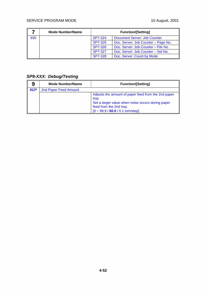
SERVICE PROGRAM MODE 10 August, 2001
4-52
7 Mode Number/Name Function/[Setting]SP7-324 Document Server: Job CounterSP7-325 Doc. Server: Job Counter – Page No.SP7-326 Doc. Server: Job Counter – File No.SP7-327 Doc. Server: Job Counter – Set No.
930
SP7-328 Doc. Server: Count by Mode
SP9-XXX: Debug/Testing
9 Mode Number/Name Function/[Setting]2nd Paper Feed Amount913*
Adjusts the amount of paper feed from the 2nd papertray.Set a larger value when noise occurs during paperfeed from the 2nd tray.[0 ~ 99.9 / 60.0 / 0.1 mm/step]
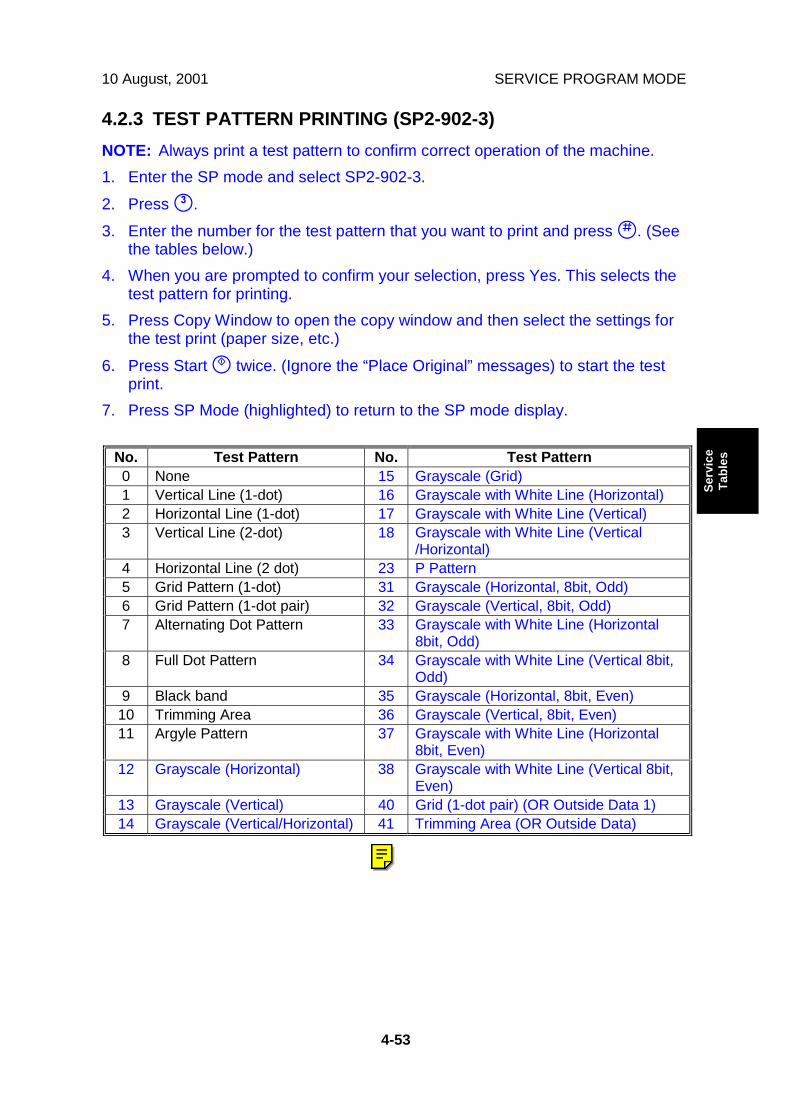
10 August, 2001 SERVICE PROGRAM MODE
4-53
Serv
ice
Tabl
es
4.2.3 TEST PATTERN PRINTING (SP2-902-3)NOTE: Always print a test pattern to confirm correct operation of the machine.1. Enter the SP mode and select SP2-902-3.2. Press !.3. Enter the number for the test pattern that you want to print and press ". (See
the tables below.)4. When you are prompted to confirm your selection, press Yes. This selects the
test pattern for printing.5. Press Copy Window to open the copy window and then select the settings for
the test print (paper size, etc.)6. Press Start # twice. (Ignore the “Place Original” messages) to start the test
print.7. Press SP Mode (highlighted) to return to the SP mode display.
No. Test Pattern No. Test Pattern0 None 15 Grayscale (Grid)1 Vertical Line (1-dot) 16 Grayscale with White Line (Horizontal)2 Horizontal Line (1-dot) 17 Grayscale with White Line (Vertical)3 Vertical Line (2-dot) 18 Grayscale with White Line (Vertical
/Horizontal)4 Horizontal Line (2 dot) 23 P Pattern5 Grid Pattern (1-dot) 31 Grayscale (Horizontal, 8bit, Odd)6 Grid Pattern (1-dot pair) 32 Grayscale (Vertical, 8bit, Odd)7 Alternating Dot Pattern 33 Grayscale with White Line (Horizontal
8bit, Odd)8 Full Dot Pattern 34 Grayscale with White Line (Vertical 8bit,
Odd)9 Black band 35 Grayscale (Horizontal, 8bit, Even)10 Trimming Area 36 Grayscale (Vertical, 8bit, Even)11 Argyle Pattern 37 Grayscale with White Line (Horizontal
8bit, Even)12 Grayscale (Horizontal) 38 Grayscale with White Line (Vertical 8bit,
Even)13 Grayscale (Vertical) 40 Grid (1-dot pair) (OR Outside Data 1)14 Grayscale (Vertical/Horizontal) 41 Trimming Area (OR Outside Data)
Ricoh Technical Services
RTB 6 Patterns 40 and 41 - descriptions changed

SERVICE PROGRAM MODE 10 August, 2001
4-54
4.2.4 INPUT CHECK
Main Machine Input Check (SP5-803)
1. Enter the SP mode and select SP5-803.2. Enter the number (1 – 11) for the item that you want to check. A small box will
be displayed on the SP mode screen with a series of 0’s and 1’s.The meaning of the display is as follows.
0 0 0 0 0 0 0 0Bit 7 6 5 4 3 2 1 0
3. Check the status of each item against the corresponding bit numbers listed inthe table below.
ReadingNumber Bit Description 0 17 Paper Height Sensor 2 (2nd
Tray)Activated Deactivated
6 Paper Height Sensor 1 (2ndTray)
Activated Deactivated
5 Paper Height Sensor 2 (1stTray)
Activated Deactivated
4 Paper Height Sensor 1 (1stTray)
Activated Deactivated
3 Paper End Sensor (2nd Tray) Paper End Paper is present2 Upper Relay Sensor Activated Deactivated1 Lower Right Cover Open Closed Open
1
0 Not used7 Paper Exit Sensor Activated Deactivated6 Fusing Unit Unit Set Unit not set5 PCU Set Activated Deactivated4 New PCU Sensor Activated Deactivated3 Interchange Exit Sensor Activated Deactivated2 1 bin Tray Unit Set Unit Set Unit not set1 1 bin Tray Paper Sensor Activated Deactivated
2
0 Interchange Unit Set Unit Set Unit not set7 Bridge Exit Sensor Activated Deactivated6 Not used5 Bridge Paper Sensor Activated Deactivated4 Bridge Right Guide Switch Activated Deactivated3 Bridge Left Guide Switch Activated Deactivated2 Bridge Unit Set Unit Set Unit not set1 Bridge Fan Motor Lock Locked Unlocked
3
0 Shift Tray Unit Set Unit Set Unit not set

10 August, 2001 SERVICE PROGRAM MODE
4-55
Serv
ice
Tabl
es
ReadingNumber Bit Description 0 17 Wake up Signal Not detected Detected6 Lower Relay Sensor Activated Deactivated5 Vertical Transport Sensor
(Optional paper tray unit)Activated Deactivated
4 3rd Tray Paper Size Activated Deactivated3 4th Tray Paper Size Activated Deactivated2 Motor Lock (Optional paper tray
unit)Not locked Locked
1 Height Sensor (Optional papertray unit)
Activated Deactivated
4
0 Unit Set (Optional paper trayunit)
Unit set Unit not set
7 Fusing Drive Release Solenoid Activated Deactivated6 Main Motor Brake Signal Not active Active5 Main Motor On Signal Activated Deactivated4 Main Motor Rotation Direction
SignalNot active Active
3 3rd Paper End Sensor Paper End Paper is present2 4th Paper End Sensor Paper End Paper is present1 3rd Paper Height Sensor Deactivated Activated
5
0 4th Paper Height Sensor Deactivated Activated7 Duplex Unit Set Unit set Unit not set6 Total Counter Not detected Detected5 By-pass Tray Unit Set Detected Not detected4 By-pass Paper End Sensor Paper End Paper is present3 By-pass Paper Size 2 Activated Deactivated2 By-pass Paper Size 1 Activated Deactivated1 By-pass Paper Size 4 Activated Deactivated
6
0 By-pass Paper Size 3 Activated Deactivated7 Not Used6 Not Used5 Not Used4 Not Used3 Key Counter Set Detected Not detected2 Key Card Set Detected Not detected1 Polygon Motor Ready Signal Ready Not ready
7
0 Not Used

SERVICE PROGRAM MODE 10 August, 2001
4-56
ReadingNumber Bit Description 0 17 Dip Switch - 4 On Off6 Dip Switch - 3 Off On5 Dip Switch - 2 Off On4 Dip Switch - 1 Off On3 Not Used2 Front Safety Sw – 5V On Off1 Front Safety Sw – 24V Off On
8
0 Main Motor Ready Signal Ready Not ready7 Not used6 Relay Off Signal Not detected Detected5 Toner Bottle Motor Lock Locked Not locked4 Right Cover Open Closed Open3 Registration Sensor Activated Deactivated2 Exhaust Fan Lock Not locked Locked1 Interchange Cover Open Closed Open
9
0 Paper Overflow Sensor Activated Deactivated7 Not Used8 Not Used5 Not Used4 Upper Relay Sensor Activated Deactivated3 1st Paper End Paper End Paper is present2 2nd Paper Lift Sensor Activated Deactivated1 1st Paper Lift Sensor Activated Deactivated
10
0 Not Used7 2nd Paper Size 1 Activated Deactivated6 2nd Paper Size 2 Activated Deactivated5 2nd Paper Size 3 Activated Deactivated4 2nd Paper Size 4 Activated Deactivated3 1st Paper Size 1 Activated Deactivated2 1st Paper Size 2 Activated Deactivated1 1st Paper Size 3 Activated Deactivated
11
0 1st Paper Size 4 Activated Deactivated
NOTE: Numbers 12 to 14 are not used for this machine.

10 August, 2001 SERVICE PROGRAM MODE
4-57
Serv
ice
Tabl
es
ARDF Input Check (SP6-007)
1. Enter the SP mode and select SP6-007.2. Enter the number (1 – 11) for the item that you want to check. A small box will
be displayed on the SP mode screen with a series of 0’s and 1’s, as shownbelow. However, only bit 0 at the right side of the screen is valid.
0 0 0 0 0 0 0 0Bit 7 6 5 4 3 2 1 0
3. Check the status of bit 0 for the required item listed in the table below.
ReadingNo.. Description 0 11 Original set sensor Paper not detected Paper detected2 Original width sensor 1 (W1) Paper not detected Paper detected3 Original width sensor 2 (W2) Paper not detected Paper detected4 Original length sensor 1 (L1) Paper not detected Paper detected5 Original length sensor 2 (L2) Paper not detected Paper detected6 Original trailing edge sensor Paper not detected Paper detected7 ADF cover sensor Cover closed Cover opened8 DF position sensor ADF closed ADF opened9 Registration sensor Paper not detected Paper detected10 Exit sensor Paper not detected Paper detected11 Inverter sensor Paper not detected Paper detected
W1
W2
B027S600.WMF
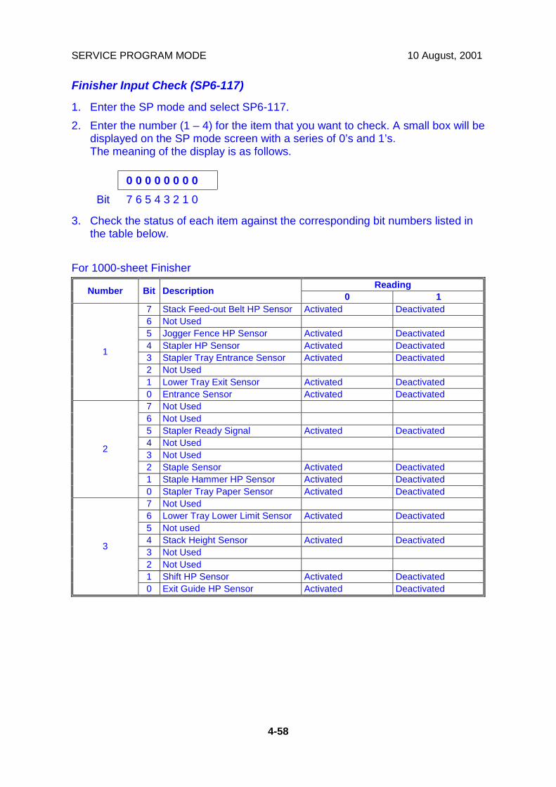
SERVICE PROGRAM MODE 10 August, 2001
4-58
Finisher Input Check (SP6-117)
1. Enter the SP mode and select SP6-117.2. Enter the number (1 – 4) for the item that you want to check. A small box will be
displayed on the SP mode screen with a series of 0’s and 1’s.The meaning of the display is as follows.
0 0 0 0 0 0 0 0Bit 7 6 5 4 3 2 1 0
3. Check the status of each item against the corresponding bit numbers listed inthe table below.
For 1000-sheet FinisherReadingNumber Bit Description 0 1
7 Stack Feed-out Belt HP Sensor Activated Deactivated6 Not Used5 Jogger Fence HP Sensor Activated Deactivated4 Stapler HP Sensor Activated Deactivated3 Stapler Tray Entrance Sensor Activated Deactivated2 Not Used1 Lower Tray Exit Sensor Activated Deactivated
1
0 Entrance Sensor Activated Deactivated7 Not Used6 Not Used5 Stapler Ready Signal Activated Deactivated4 Not Used3 Not Used2 Staple Sensor Activated Deactivated1 Staple Hammer HP Sensor Activated Deactivated
2
0 Stapler Tray Paper Sensor Activated Deactivated7 Not Used6 Lower Tray Lower Limit Sensor Activated Deactivated5 Not used4 Stack Height Sensor Activated Deactivated3 Not Used2 Not Used1 Shift HP Sensor Activated Deactivated
3
0 Exit Guide HP Sensor Activated Deactivated

10 August, 2001 SERVICE PROGRAM MODE
4-59
Serv
ice
Tabl
es
ReadingNumber Bit Description 0 17 Not Used6 Not Used5 Not Used4 Not Used3 Upper Tray Paper Limit Sensor Activated Deactivated2 Not Used1 Not Used
3
0 Not Used
For 500-sheet FinisherReadingNumber Bit Description 0 1
7 Stack Near-limit Sensor Activated Deactivated6 Tray Upper Limit Sensor Activated Deactivated5 Lever Sensor Activated Deactivated4 Stack Height Sensor Activated Deactivated3 Top Cover Sensor Closed Opened2 Jogger HP Sensor Activated Deactivated1 Exit Sensor Activated Deactivated
1
0 Entrance Sensor Activated Deactivated7 Not Used6 Not Used5 Not Used4 Staple Unit Lock Locked Not Locked3 Staple Cartridge Sensor Activated Deactivated2 Staple End Sensor Activated Deactivated1 Staple Hammer HP Sensor Activated Deactivated
2
0 Staple Unit Cover Switch Closed Opened

SERVICE PROGRAM MODE 10 August, 2001
4-60
4.2.5 OUTPUT CHECKNOTE: Motors keep turning in this mode regardless of upper or lower limit sensor
signals. To prevent mechanical or electrical damage, do not keep anelectrical component on for a long time.
Main Machine Output Check (SP5-804)
1. Open SP mode 5-804.2. Select the SP number that corresponds to the component you wish to check.
(Refer to the table on the next page.)3. Press On then press Off to test the selected item.
NOTE: You cannot exit and close this display until you press off to switch offthe output check currently executing. Do not keep an electricalcomponent switched on for a long time.
Output Check TableNOTE: Pull out the tray before performing the output checks 25, 26, 29, and 30.
Number Description0 Not used1 Main motor (forward)2 Main motor (Reverse) Do not use3 Registration clutch4 Not used5 Toner supply motor6 Exhaust fan (High Speed)7 Exhaust fan (Low Speed)8 By-pass feed clutch9 Upper paper feed clutch
10 Lower paper feed clutch11 Upper paper lift motor (Up)12 Upper paper lift motor (Down)13 Lower paper lift motor (Up)
B027S502.WMF
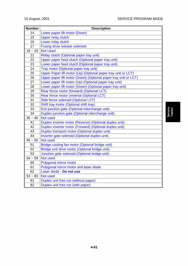
10 August, 2001 SERVICE PROGRAM MODE
4-61
Serv
ice
Tabl
es
Number Description14 Lower paper lift motor (Down)15 Upper relay clutch16 Lower relay clutch17 Fusing drive release solenoid
18 ~ 20 Not Used21 Relay clutch (Optional paper tray unit)22 Upper paper feed clutch (Optional paper tray unit)23 Lower paper feed clutch (Optional paper tray unit)24 Tray motor (Optional paper tray unit)25 Upper Paper lift motor (Up) (Optional paper tray unit or LCT)26 Upper paper lift motor (Down) (Optional paper tray unit or LCT)27 Lower paper lift motor (Up) (Optional paper tray unit)28 Lower paper lift motor (Down) (Optional paper tray unit)29 Rear fence motor (forward) (Optional LCT)30 Rear fence motor (reverse (Optional LCT)31 Side fence solenoid (Optional LCT)32 Shift tray motor (Optional shift tray)33 Exit junction gate (Optional interchange unit)34 Duplex junction gate (Optional interchange unit)
35 ~ 40 Not used41 Duplex inverter motor (Reverse) (Optional duplex unit)42 Duplex inverter motor (Forward) (Optional duplex unit)43 Duplex transport motor (Optional duplex unit)44 Inverter gate solenoid (Optional duplex unit)
45 ~ 50 Not used51 Bridge cooling fan motor (Optional bridge unit)52 Bridge unit drive motor (Optional bridge unit)53 Junction gate solenoid (Optional bridge unit)
54 ~ 59 Not used60 Polygonal mirror motor61 Polygonal mirror motor and laser diode62 Laser diode - Do not use
53 ~ 80 Not used81 Duplex unit free run (without paper)82 Duplex unit free run (with paper)

SERVICE PROGRAM MODE 10 August, 2001
4-62
ARDF Output Check (SP6-008)
1. Open SP mode SP6-008.2. Select the SP number that corresponds to the component you wish to check.
(Refer to the table below.)3. Press On then press Off to test the selected item. You cannot exit and close
this display until you click Off to switch off the output check currently executing.
No. Description1 Feed Motor (Forward)2 Feed Motor (Reverse)3 Transport Motor (Forward)4 Feed Clutch5 Pick-up Solenoid6 Junction Gate Solenoid7 Stamp Solenoid
Finisher Output Check (SP6-118)
1. Open SP mode SP6-118.2. Select the SP number that corresponds to the component you wish to check.
(Refer to the table below.)3. Press On then press Off to test the selected item. You cannot exit and close
this display until you click Off to switch off the output check currently executing.
No. Description1000-sheet finisher 500-sheet finisher
1 Upper Transport Motor Main Motor2 Shift Tray Lift Motor Output Tray Motor3 Staple Hammer Motor Stapler Motor4 Shift Motor Jogger Motor5 Lower Transport Motor Not Used6 Shift Tray Exit Motor Not Used7 Tray Junction Gate Solenoid Not Used8 Jogger Motor Not Used9 Stapler Motor Not Used10 Stapler Junction Gate Solenoid Not Used11 Positioning Roller Solenoid Not Used12 Stack Feed-out Motor Not Used13 Exit Guide Plate Motor Not Used14 Not Used Paddle Roller Solenoid15 Not Used Exit Unit Gear Solenoid16 Not Used Stack Height Lever Solenoid17

10 August, 2001 SERVICE PROGRAM MODE
4-63
Serv
ice
Tabl
es
4.2.6 SMC DATA LISTS (SP5-990)
1. Open SP mode 5-990 and select the number corresponding to the list that youwish to print.
SMC (System Parameter and Data Lists)1 All Data List2 SP Mode Data List3 UP Mode Data List4 Logging Data List5 Self-Diagnostics Results List7 NIB Summary21 Copy UP Mode List22 Scanner SP Mode List23 Scanner UP Mode List
2. Touch “Execute” on the touch panel3. Select. “Single Face” or “Both Face” then touch “Execute” to start printing.4. After printing the list, press Exit twice to close the SP Mode screen and return
to copy mode.
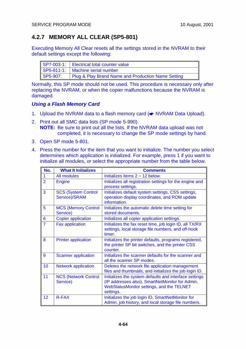
SERVICE PROGRAM MODE 10 August, 2001
4-64
4.2.7 MEMORY ALL CLEAR (SP5-801)
Executing Memory All Clear resets all the settings stored in the NVRAM to theirdefault settings except the following:
SP7-003-1: Electrical total counter valueSP5-811-1: Machine serial numberSP5-907: Plug & Play Brand Name and Production Name Setting
Normally, this SP mode should not be used. This procedure is necessary only afterreplacing the NVRAM, or when the copier malfunctions because the NVRAM isdamaged.Using a Flash Memory Card
1. Upload the NVRAM data to a flash memory card (☛ NVRAM Data Upload).2. Print out all SMC data lists (SP mode 5-990).
NOTE: Be sure to print out all the lists. If the NVRAM data upload was notcompleted, it is necessary to change the SP mode settings by hand.
3. Open SP mode 5-801.4. Press the number for the item that you want to initialize. The number you select
determines which application is initialized. For example, press 1 if you want toinitialize all modules, or select the appropriate number from the table below.
No. What It Initializes Comments1 All modules Initializes items 2 ~ 12 below.2 Engine Initializes all registration settings for the engine and
process settings.3 SCS (System Control
Service)/SRAMInitializes default system settings, CSS settings,operation display coordinates, and ROM updateinformation.
5 MCS (Memory ControlService)
Initializes the automatic delete time setting forstored documents.
6 Copier application Initializes all copier application settings.7 Fax application Initializes the fax reset time, job login ID, all TX/RX
settings, local storage file numbers, and off-hooktimer.
8 Printer application Initializes the printer defaults, programs registered,the printer SP bit switches, and the printer CSScounter.
9 Scanner application Initializes the scanner defaults for the scanner andall the scanner SP modes.
10 Network application Deletes the network file application managementfiles and thumbnails, and initializes the job login ID.
11 NCS (Network ControlService)
Initializes the system defaults and interface settings(IP addresses also), SmartNetMonitor for Admin,WebStatusMonitor settings, and the TELNETsettings.
12 R-FAX Initializes the job login ID, SmartNetMonitor forAdmin, job history, and local storage file numbers.
10 August, 2001 SERVICE PROGRAM MODE
4-65
Serv
ice
Tabl
es
5. Press Execute and turn the main switch off and back on.6. Download the NVRAM data from a flash memory card (☛ NVRAM Data
Download).
Without Using a Flash Memory CardIf there is no flash memory card, follow the steps below.
1. Execute SP5-990 to print out all SMC Data Lists.2. Open SP mode 5-801.3. Press the number for the item that you want to initialize.4. Press Execute and turn the main switch off and back on.5. Make sure that you do the following:
• Do the printer and scanner registration and magnification adjustments (☛ 3Replacement and Adjustment, “Copy Adjustments”).
• Do the touch screen calibration (☛ 3 Replacement and Adjustment, “touchscreen calibration”).
• Referring to the SMC data lists, re-enter any values, which had beenchanged from their factory settings.
• Do SP 3-001-2 (ID Sensor Initial Setting) and SP4-911-1 (HDD mediacheck).
• Do the white level adjustment (☛ Section 6.8.2 Standard White DensityAdjustment)
6. Check the copy quality and the paper path, and do any necessary adjustments.
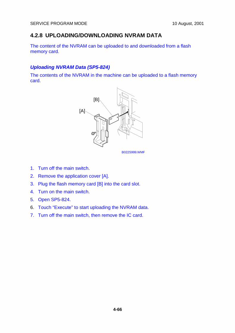
SERVICE PROGRAM MODE 10 August, 2001
4-66
4.2.8 UPLOADING/DOWNLOADING NVRAM DATA
The content of the NVRAM can be uploaded to and downloaded from a flashmemory card.
Uploading NVRAM Data (SP5-824)The contents of the NVRAM in the machine can be uploaded to a flash memorycard.
1. Turn off the main switch.2. Remove the application cover [A].3. Plug the flash memory card [B] into the card slot.4. Turn on the main switch.5. Open SP5-824.6. Touch “Execute” to start uploading the NVRAM data.7. Turn off the main switch, then remove the IC card.
B022S999.WMF
[A]
[B]
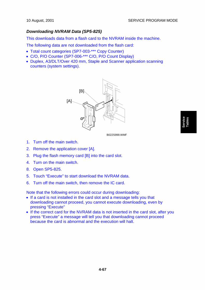
10 August, 2001 SERVICE PROGRAM MODE
4-67
Serv
ice
Tabl
es
Downloading NVRAM Data (SP5-825)This downloads data from a flash card to the NVRAM inside the machine.The following data are not downloaded from the flash card:• Total count categories (SP7-003-*** Copy Counter)• C/O, P/O Counter (SP7-006-*** C/O, P/O Count Display)• Duplex, A3/DLT/Over 420 mm, Staple and Scanner application scanning
counters (system settings).
1. Turn off the main switch.2. Remove the application cover [A].3. Plug the flash memory card [B] into the card slot.4. Turn on the main switch.8. Open SP5-825.5. Touch “Execute” to start download the NVRAM data.6. Turn off the main switch, then remove the IC card.
Note that the following errors could occur during downloading:• If a card is not installed in the card slot and a message tells you that
downloading cannot proceed, you cannot execute downloading, even bypressing “Execute”
• If the correct card for the NVRAM data is not inserted in the card slot, after youpress “Execute” a message will tell you that downloading cannot proceedbecause the card is abnormal and the execution will halt.
B022S999.WMF
[A]
[B]

SERVICE PROGRAM MODE 10 August, 2001
4-68
4.2.9 APS OUTPUT DISPLAY (SP4-301)
When open this SP, a small box will be displayed on the SP mode screen with aseries of 0’s and 1’s. The meaning of the display is as follows.
0 0 0 0 0 0 0 0Bit 7 6 5 4 3 2 1 01 = Paper detected
Bit Description
7 L16 L25 L34 L43 W22 W11 Not Used0 Not Used
W2
W1
L1L2
L3L4
B027S511.WMF
W2
W1
L1L2
B027S512.WMF
[230V Machine] [115V Machine]

10 August, 2001 SERVICE PROGRAM MODE
4-69
Serv
ice
Tabl
es
4.2.10 DF APS SENSOR OUTPUT DISPLAY (SP6-901)
When open this SP, a small box will be displayed on the SP mode screen with aseries of 0’s and 1’s. The meaning of the display is as follows.
0 0 0 0 0 0 0 0Bit 7 6 5 4 3 2 1 0
1 = Paper detectedillustration to be changed
Large SmallW1 0 0 1 1W2 0 1 0 1
Bit Description
7 Not Used6 Not Used5 W14 W23 L12 L21 L30 Not Used
W1
W2
B027S600.WMF

SERVICE PROGRAM MODE 10 August, 2001
4-70
4.2.11 NIP BAND WIDTH MEASUREMENT (SP1-109)
When paper wrinkling or image off-set occurs, the pressure from the pressure rollercan be adjusted by changing the position of the pressure springs. At this time, thenip band width can also be checked with SP1-109, as follows.
1. Do a free run (SP5-802) for about 50 sheets.2. Access SP1-109 and press the “1” key.3. Press Copy Window to return to the copy window.4. Place an OHP sheet (A4/8.5”x11” sideways) on the by-pass tray or in the 2nd
paper tray.5. Press the “Start” key.
The OHP sheet is stopped in the fusing unit for about 20 seconds, then it willbe fed automatically.
6. Check the nip band width [A]. The relationship between the position of thepressure spring and the band width is as follows.NOTE: Check the nip band width around the center of the OHP.
1. Pressure spring position Nip band widthUpper (default position) 5.2 ± 0.5 mmLower 5.3 ± 0.5 mm
2. Envelope feed mode (green lever down) at thedefault pressure spring position
4.7 ± 0.5 mm
If the width is out of the above specification, the pressure spring should bereplaced.
Pape
r fee
d di
rect
ion
OHP
B027S513.WMF
[A]

10 August, 2001 PROGRAM DOWNLOAD
4-71
Serv
ice
Tabl
es
4.3 PROGRAM DOWNLOAD
1. Turn off the main power switch.2. Remove the application cover [A].3. Insert the IC card [B] containing the software you wish to download into the
card slot of the controller.4. Turn on the main power.5. Follow the instructions displayed on the LCD panel6. Monitor the downloading status on the operation panel.
• While downloading is in progress, the LCD will display “Writing”. Whendownloading has been completed, the panel will display “OK”.
• For operation panel software, the Start key lights red while downloading is inprogress, and then lights green again after downloading is completed.
$CAUTIONNever switch off the power while downloading. Switching off the power while thenew software is being downloading will damage the boot files in the controller.
7. After confirming that downloading is completed, turn off the main power andremove the IC card.
8. If more software needs to be downloaded, repeat steps 1 to 7.9. Turn the main power on and confirm that the new software loads and that the
machine starts normally.
NOTE: If the download failed, an error message will appear on the panel. Then,download the firmware again using the IC card as usual.
B022S999.WMF
[A]
[B]
Ricoh Technical Services
RTB 10 Downloading scanner firmware: Scanner settings must be reset (Copier SP5-801-009)

SOFTWARE RESET 10 August, 2001
4-72
4.4 SOFTWARE RESETThe software can be rebooted when the machine hangs up. Use the followingprocedure.Turn the main power switch off and on.-or-Press and hold down ! " together for over 10 seconds. When the machinebeeps once release both buttons. After “Now loading. Please wait” is displayed fora few seconds the copy window will open. The machine is ready for normaloperation.
4.5 SYSTEM SETTINGS AND COPY SETTING RESET4.5.1 SYSTEM SETTING RESET
The system settings in the UP mode can be reset to their defaults. Use thefollowing procedure.
1. Press User Tools/Counter .2. Hold down " and then press System Settings.
NOTE: You must press " first.
3. When the message prompts you to confirm that you want to reset the systemsettings, press Yes.
4. When the message tells you that the settings have been reset, press Exit.
B027S503.WMF

10 August, 2001 SYSTEM SETTINGS AND COPY SETTING RESET
4-73
Serv
ice
Tabl
es
4.5.2 COPIER SETTING RESET
The copy settings in the UP mode can be reset to their defaults. Use the followingprocedure.
1. Press User Tools/Counter .2. Hold down " and then press Copier/Document Server Settings.
NOTE: You must press " first.
3. When the message prompts you to confirm that you want to reset the CopierDocument Server settings, press Yes.
4. When the message tells you that the settings have been reset, press Exit.
B027S504.WMF
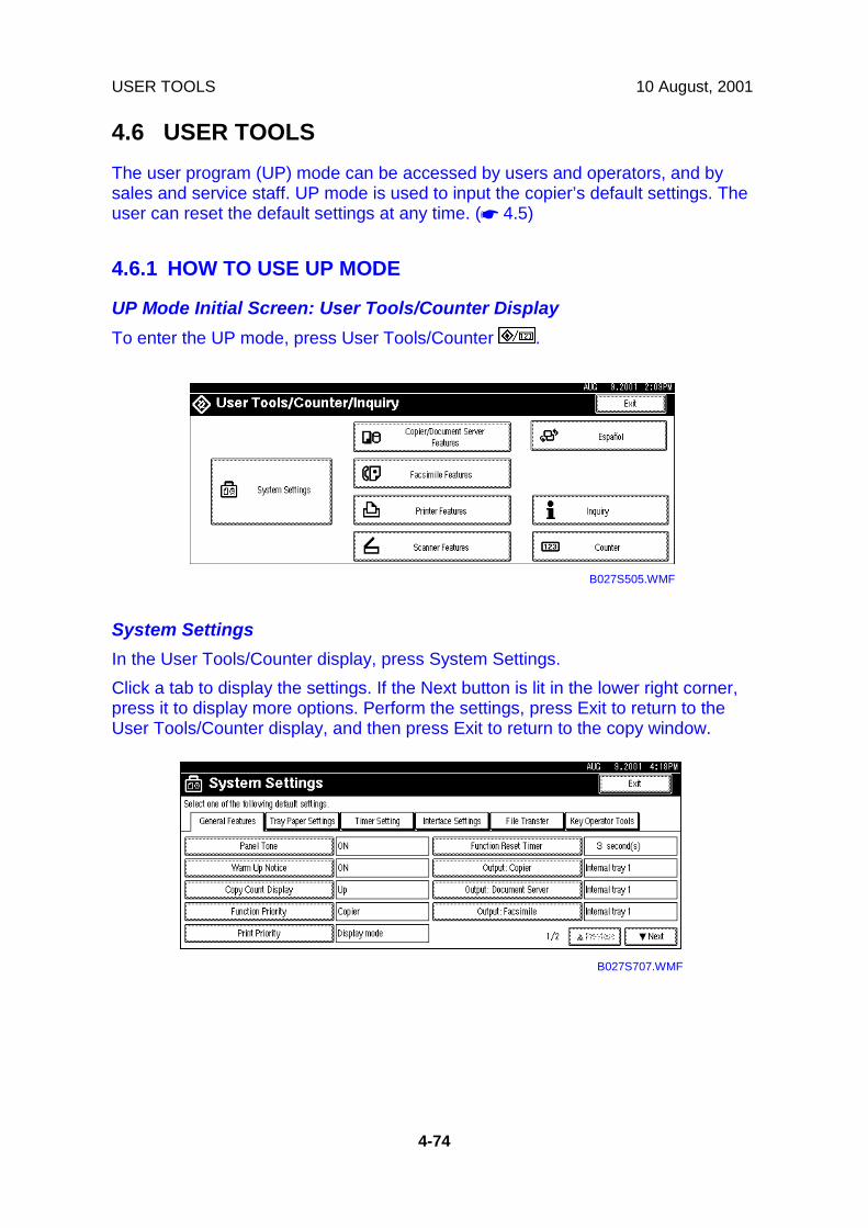
USER TOOLS 10 August, 2001
4-74
4.6 USER TOOLSThe user program (UP) mode can be accessed by users and operators, and bysales and service staff. UP mode is used to input the copier’s default settings. Theuser can reset the default settings at any time. (☛ 4.5)
4.6.1 HOW TO USE UP MODE
UP Mode Initial Screen: User Tools/Counter DisplayTo enter the UP mode, press User Tools/Counter .
System SettingsIn the User Tools/Counter display, press System Settings.Click a tab to display the settings. If the Next button is lit in the lower right corner,press it to display more options. Perform the settings, press Exit to return to theUser Tools/Counter display, and then press Exit to return to the copy window.
B027S505.WMF
B027S707.WMF

10 August, 2001 USER TOOLS
4-75
Serv
ice
Tabl
es
Copier/Document Server FeaturesIn the User/Tools Counter display, press Copy/Document Server Settings.Click a tab to display the settings. If the Next button is lit in the lower right corner,press it to display more options. Perform the settings, press Exit to return to theUser Tools/Counter display, and then press Exit to return to the copy window.
Printer, Facsimile, Scanner SettingsIn the User/Tools Counter display, press Printer Settings, Facsimile, or ScannerSettings to open the appropriate screen and then click the tab to display moresettings. The screen below shows the Printer Features screen.
InquiryIn the User/Tools Counter display, press Inquiry.The following SP mode settings will be displayed.
• Service Telephone Number (SP5-812-1)• Sales Telephone Number (SP812-4)• Consumable Telephone Number (SP812-3)• Toner Name (SP-841)
B027S701.WMF
B027S705.WMF
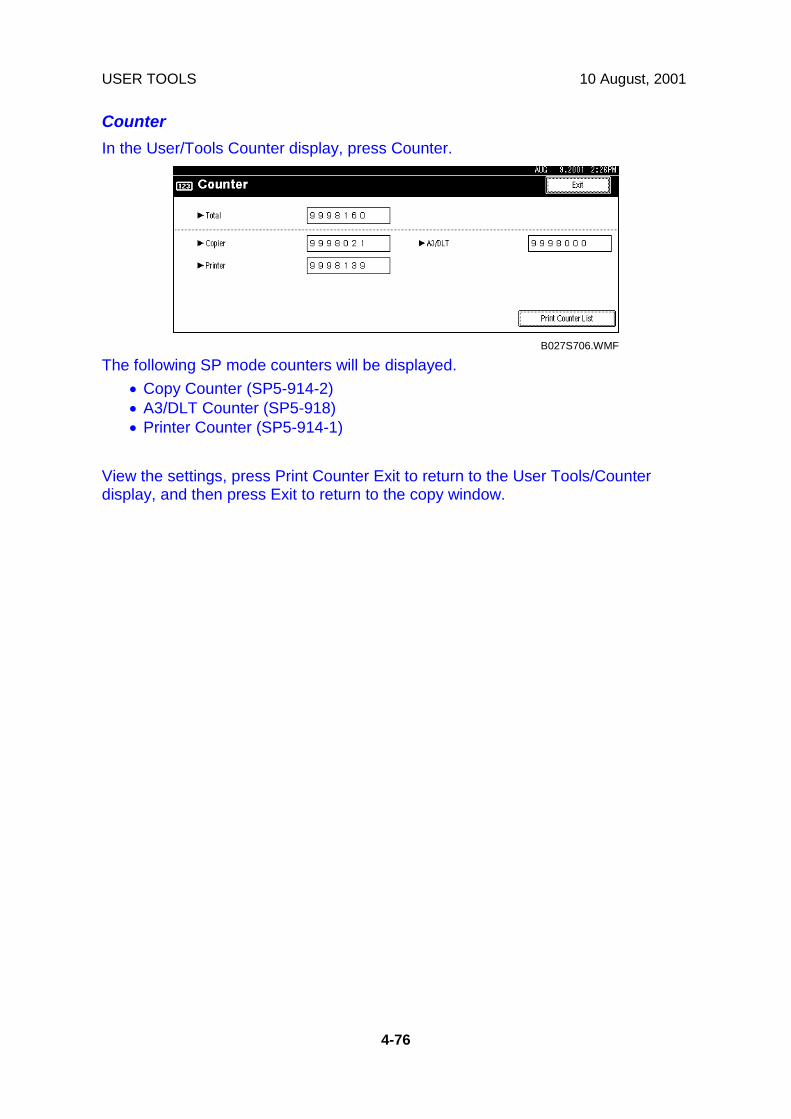
USER TOOLS 10 August, 2001
4-76
CounterIn the User/Tools Counter display, press Counter.
The following SP mode counters will be displayed.• Copy Counter (SP5-914-2)• A3/DLT Counter (SP5-918)• Printer Counter (SP5-914-1)
View the settings, press Print Counter Exit to return to the User Tools/Counterdisplay, and then press Exit to return to the copy window.
B027S706.WMF

10 August, 2001 LEDS
4-77
Serv
ice
Tabl
es
4.7 LEDSController
Number Normal Controller SoftwareDownload
Error
LED 1 Off Blinking OffLED 2 Blinking Blinking Lit or OffLED 3
(+5V line)Lit Lit Lit
SBCU
Number Normal SBCU SoftwareDownload
Error
LED 1 Lit Lit Off or Blinking
LED 2 Blinking Lit Lit (except downloading)or Off
IPU
Number Normal ErrorLED 1 Lit Off or Blinking
4.8 DIP SWITCHESController: DIP SW2
DIP SW No. ON OFF1 IC Card Boot System ROM Boot234
Keep at “OFF”
SBCU: DIP SW102DIP SW No. Function ON OFF
123
DestinationOn: JapanOnOn
Off: NAOnOn
On: EU/AsiaOffOn
Off: Not UsedOffOn
4 Not used OFF (Do not change)
Ricoh Technical Services
RTB 9: Dip switch definitions corrected RTB 11b, 24: Settings changed for China

SPECIAL TOOLS AND LUBRICANTS 10 August, 2001
4-78
4.9 SPECIAL TOOLS AND LUBRICANTS4.9.1 SPECIAL TOOLS
Part Number Description Q’tyA2929500 S5S Test Chart (10 pcs/set) 1A0069104 Scanner Positioning Pin (4 pcs/set) 1A0299387 Digital Multimeter - FLUKE 87 1A2309351 Case - Flash Memory Card 1N8036701 Flash Memory Card - 4MB 1B0279099 NVRAM - Minus Counter 1A2309003 Adjustment Cam – Laser Unit 1A2679002 Positioning Pin - Laser Unit 1
4.9.2 LUBRICANTS
Part Number Description Q’tyA0289300 Grease Barrierta - JFE 5 5/2 152039501 Silicone Grease G-501 1
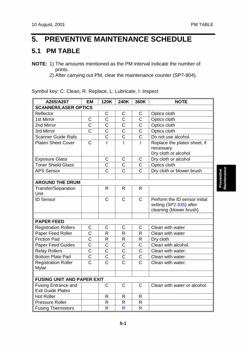
10 August, 2001 PM TABLE
5-1
Prev
entiv
eM
aint
enan
ce
5. PREVENTIVE MAINTENANCE SCHEDULE5.1 PM TABLE
NOTE: 1) The amounts mentioned as the PM interval indicate the number ofprints.
2) After carrying out PM, clear the maintenance counter (SP7-804).
Symbol key: C: Clean, R: Replace, L: Lubricate, I: Inspect
A265/A267 EM 120K 240K 360K NOTESCANNER/LASER OPTICSReflector C C C Optics cloth1st Mirror C C C C Optics cloth2nd Mirror C C C C Optics cloth3rd Mirror C C C C Optics clothScanner Guide Rails C C C Do not use alcohol.Platen Sheet Cover C I I I Replace the platen sheet, if
necessary.Dry cloth or alcohol
Exposure Glass C C C Dry cloth or alcoholToner Shield Glass C C C Optics clothAPS Sensor C C C Dry cloth or blower brush
AROUND THE DRUMTransfer/SeparationUnit
R R R
ID Sensor C C C Perform the ID sensor initialsetting (SP2-935) aftercleaning (blower brush)
PAPER FEEDRegistration Rollers C C C C Clean with waterPaper Feed Roller C R R R Clean with waterFriction Pad C R R R Dry clothPaper Feed Guides C C C C Clean with alcohol.Relay Rollers C C C C Clean with water.Bottom Plate Pad C C C C Clean with water.Registration RollerMylar
C C C C Clean with water.
FUSING UNIT AND PAPER EXITFusing Entrance andExit Guide Plates
C C C Clean with water or alcohol.
Hot Roller R R RPressure Roller R R RFusing Thermistors R R R

PM TABLE 10 August, 2001
5-2
A265/A267 EM 120K 240K 360K NOTECleaning Roller C C C Clean with water or alcohol.Cleaning RollerBushings
C C C Clean with water or alcohol.
Hot Roller Strippers R R RHot Roller andPressure RollerBushings
L L L L Grease Barrierta JFE5 5/2(A0289300)
Paper Exit GuideRibs
C C C Clean with water or alcohol.
OTHERSMain Motor DriveGear
L I I I Silicone Grease G501(see note 1)
EM 120K 240K 360K NOTEADF (for originals)Pick-up Roller C R R R Clean with waterFeed Belt C R R R Clean with waterSeparation Roller C R R R Clean with waterStamp I I I Replace if necessaryADF Exposure Glass C C C C Clean with alcoholWhite Plate C C C C Clean with alcoholPlaten Sheet C C C C Clean with alcohol
EM 120K 240K 360K NOTEPAPER TRAY UNITPaper Feed Roller C R R R Clean with waterFriction Pad C R R R Dry clothPaper Feed Guides C C C C Clean with alcohol.Relay Rollers C C C C Clean with water.Bottom Plate Pad C C C C Clean with water.Relay Clutch I I I Replace if necessaryPaper Feed Clutch I I I Replace if necessary
EM 120K 240K 360K NOTELCTPaper Feed Roller R R RPick-up Roller R R RSeparation Roller R R RTransport Rollers C C C Clean with waterBottom Plate Pad C C C Clean with waterRelay Clutch I I I Replace if necessaryPaper Feed Clutch I I I Replace if necessary
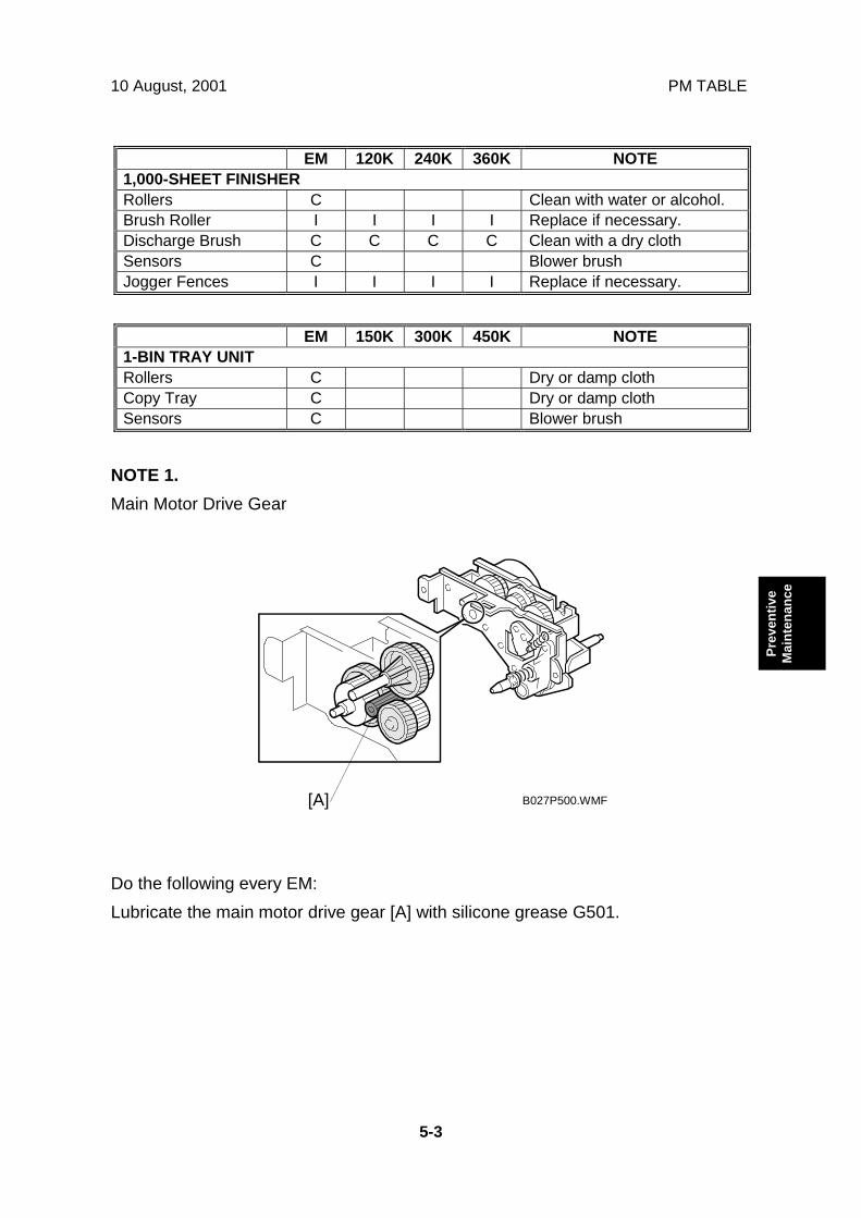
10 August, 2001 PM TABLE
5-3
Prev
entiv
eM
aint
enan
ce
EM 120K 240K 360K NOTE1,000-SHEET FINISHERRollers C Clean with water or alcohol.Brush Roller I I I I Replace if necessary.Discharge Brush C C C C Clean with a dry clothSensors C Blower brushJogger Fences I I I I Replace if necessary.
EM 150K 300K 450K NOTE1-BIN TRAY UNITRollers C Dry or damp clothCopy Tray C Dry or damp clothSensors C Blower brush
NOTE 1.Main Motor Drive Gear
Do the following every EM:Lubricate the main motor drive gear [A] with silicone grease G501.
B027P500.WMF[A]
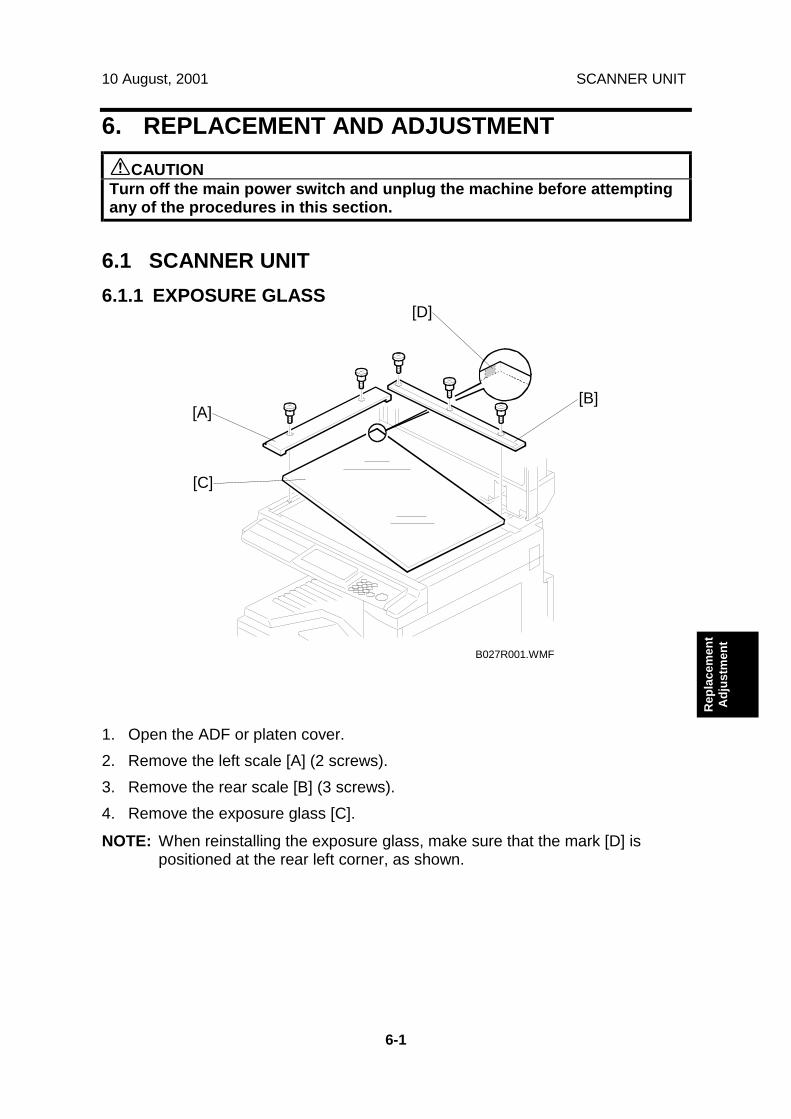
10 August, 2001 SCANNER UNIT
6-1
Rep
lace
men
tA
djus
tmen
t
6. REPLACEMENT AND ADJUSTMENT!CAUTIONTurn off the main power switch and unplug the machine before attemptingany of the procedures in this section.
6.1 SCANNER UNIT6.1.1 EXPOSURE GLASS
1. Open the ADF or platen cover.2. Remove the left scale [A] (2 screws).3. Remove the rear scale [B] (3 screws).4. Remove the exposure glass [C].
NOTE: When reinstalling the exposure glass, make sure that the mark [D] ispositioned at the rear left corner, as shown.
B027R001.WMF
[A][B]
[C]
[D]

SCANNER UNIT 10 August, 2001
6-2
6.1.2 SCANNER EXTERIOR/OPERATION PANEL
1. Remove the ADF or platen cover.2. Remove the exposure glass. (☛ 6.1.1)3. Remove the upper front cover [A] (1 screw, 1 hook).4. Remove the operation panel [B] (5 screws, 1 connector).5. Remove the right cover [C] (1 screw, 2 hooks).6. Remove the rear cover [D] (2 screws).7. Remove the left cover [E] (2 screws, 2 hooks).
B022R002.WMF[A]
[B]
[C]
[D][E]

10 August, 2001 SCANNER UNIT
6-3
Rep
lace
men
tA
djus
tmen
t
6.1.3 LENS BLOCK ASSEMBLY
1. Remove the exposure glass. (☛ 6.1.2)2. Remove the lens cover [A] (4 screws).3. Replace the lens block assembly [B] (4 screws, 1 connector, 2 clamps).
NOTE: Do not remove the screws which are locked with white paint.4. Reassemble the machine and do the scanner and printer copy adjustments. (☛
6.8)
B022R003.WMF
B022R006.WMF
[A]
[B]
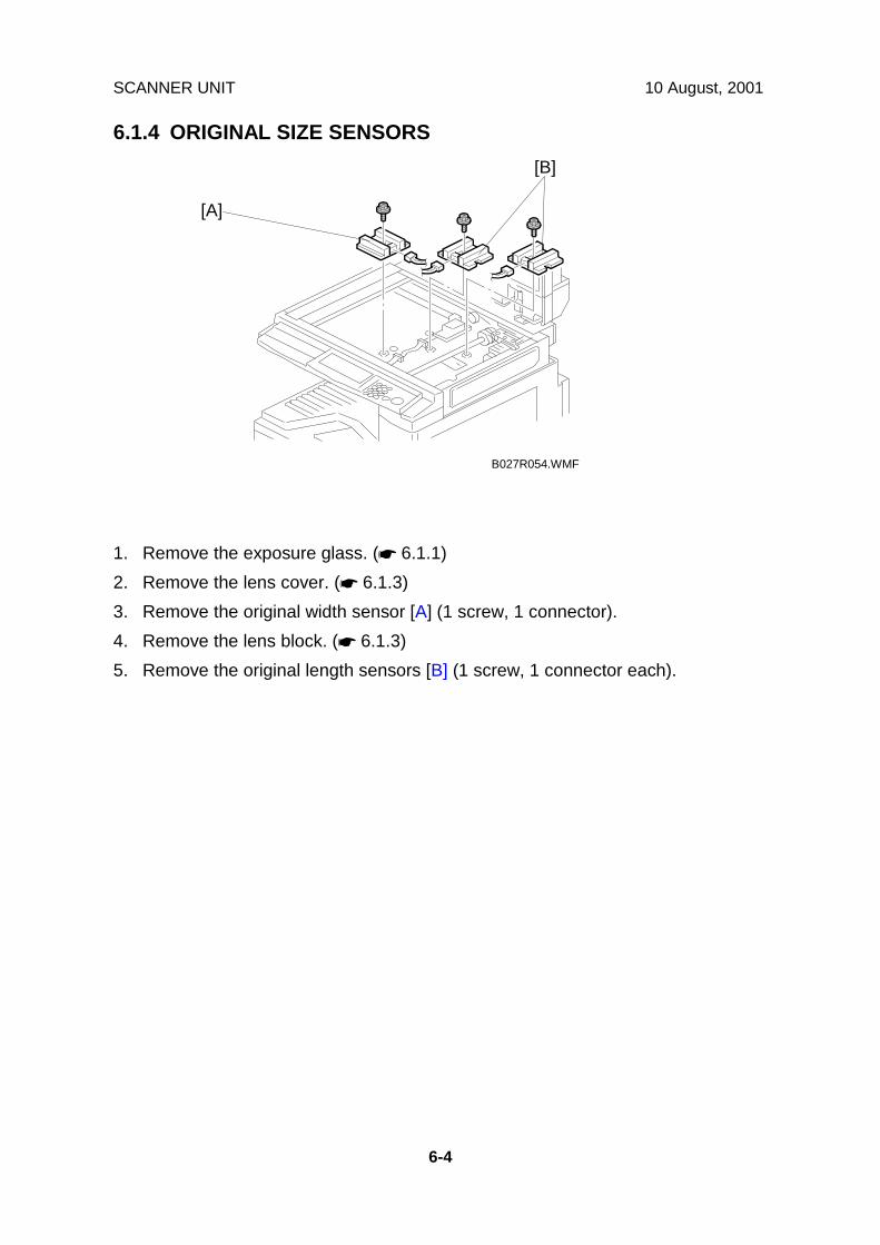
SCANNER UNIT 10 August, 2001
6-4
6.1.4 ORIGINAL SIZE SENSORS
1. Remove the exposure glass. (☛ 6.1.1)2. Remove the lens cover. (☛ 6.1.3)3. Remove the original width sensor [A] (1 screw, 1 connector).4. Remove the lens block. (☛ 6.1.3)5. Remove the original length sensors [B] (1 screw, 1 connector each).
B027R054.WMF
[A]
[B]
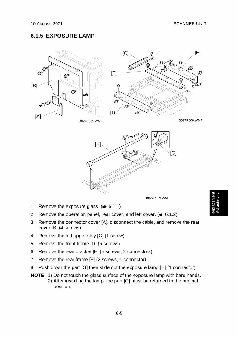
10 August, 2001 SCANNER UNIT
6-5
Rep
lace
men
tA
djus
tmen
t
6.1.5 EXPOSURE LAMP
1. Remove the exposure glass. (☛ 6.1.1)2. Remove the operation panel, rear cover, and left cover. (☛ 6.1.2)3. Remove the connector cover [A], disconnect the cable, and remove the rear
cover [B] (4 screws).4. Remove the left upper stay [C] (1 screw).5. Remove the front frame [D] (5 screws).6. Remove the rear bracket [E] (5 screws, 2 connectors).7. Remove the rear frame [F] (2 screws, 1 connector).8. Push down the part [G] then slide out the exposure lamp [H] (1 connector).NOTE: 1) Do not touch the glass surface of the exposure lamp with bare hands.
2) After installing the lamp, the part [G] must be returned to the originalposition.
B027R008.WMFB027R515.WMF
B027R009.WMF
[C]
[D]
[E]
[F]
[H]
[G]
[A]
[B]

SCANNER UNIT 10 August, 2001
6-6
6.1.6 SCANNER MOTOR/LAMP STABILIZER
1. Remove the connector cover [A], disconnect the cable, and remove the rearcover [B].
2. Replace the scanner motor [C] (3 screws, 1 spring, 1 connector).3. Replace the lamp stabilizer [D] (2 connectors).4. Reassemble the machine and do the scanner and printer copy adjustments. (☛
6.8)
B027R515.WMF
B022R007.WMF
[A]
[B]
[C][D]

10 August, 2001 SCANNER UNIT
6-7
Rep
lace
men
tA
djus
tmen
t
6.1.7 SCANNER WIRES
1. Remove the exposure glass, operation panel, and all scanner exterior covers.(☛ 6.1.1 and 6.1.2)
2. Remove the left upper stay. (☛ 6.1.5)3. Remove the front frame. (☛ 6.1.5)4. Remove the rear bracket. (☛ 6.1.5)5. Remove the rear frame. (☛ 6.1.5)6. Remove the lens cover. (☛ 6.1.3)7. Remove the lens block assembly. (☛ 6.1.3)8. Remove the front and rear scanner wire pins [A]. Then, remove the 1st
scanner.
B027R012.WMF
[A]

SCANNER UNIT 10 August, 2001
6-8
9. Remove the tension spring [B].10. Loosen the screw [C] securing the wire tension bracket [D].11. Remove the scanner drive pulley [E] (1 set screw).12. Remove the scanner wire [F].13. Wrap the new scanner wire around the pulley as shown ➀, then temporarily
secure the pulley with tape.14. Re-install the 1st scanner. Then secure the 1st and 2nd scanner with the
scanner positioning tools (P/N A0069104), as shown in the illustration on thenext page.
15. Wind the new scanner wire around the scanner drive pulley in the correct way,as shown.
16. Wind the end of the new wire with the ball as shown (➁).17. Wind the end of the new wire with the ring as shown (➂,➃, and ➄).18. Install the tension spring on the wire tension bracket (➄).19. Wind the new scanner wire for the other side as well.
B027R010.WMF
[B][C]
[D]
[F]
[E]

10 August, 2001 SCANNER UNIT
6-9
Rep
lace
men
tA
djus
tmen
t
20. Secure the 1st scanner with the scanner wire pins.21. Install the tension spring [A] to the tension bracket.22. Tighten the tension bracket [B].23. Secure the scanner wire pulley [C] (1 Allen screw).24. Remove the positioning tools [D]. After sliding the scanner to the right and left
several times, re-install the positioning tools to check the scanner wire bracketand tension bracket again.
25. Reassemble the scanner and do the scanner and printer copy adjustments (☛6.8).
B027R011.WMF
[B]
[C]
[D][A]

LASER UNIT 10 August, 2001
6-10
6.2 LASER UNIT
!WARNINGTurn off the main power switch and unplug the machine before attemptingany of the procedures in this section. Laser beams can seriously damageyour eyes.
6.2.1 CAUTION DECAL LOCATIONS
Two caution decals are located in the laser section as shown below.
LASER-4.WMF
B027R104.WMF

10 August, 2001 LASER UNIT
6-11
Rep
lace
men
tA
djus
tmen
t
6.2.2 LASER UNIT
!WARNINGTurn off the main power switch and unplug the machine before attemptingthis procedure. Laser beam can seriously damage your eyes.
1. Remove the optional finisher/bridge unit, and either the tray for the optional 1-bin tray unit or optional shift tray, if these units have been installed.
2. Remove the upper front cover [A] (1 screw, 1 hook).3. Remove the front cover [B] (2 pins).4. Remove the inner cover [C] (5 screws).5. Remove the copy tray [D] (1 hook [E]).6. Remove the toner bottle holder [F].7. Remove the laser unit [G] (2 screws, 2 connectors).8. After reassembling the machine, do the scanner and printer copy adjustments.
(☛ 6.8)
B027R101.WMF B027R102.WMF
B027R103.WMF
[A]
[B]
[D]
[C]
[E]
[F]
[G]
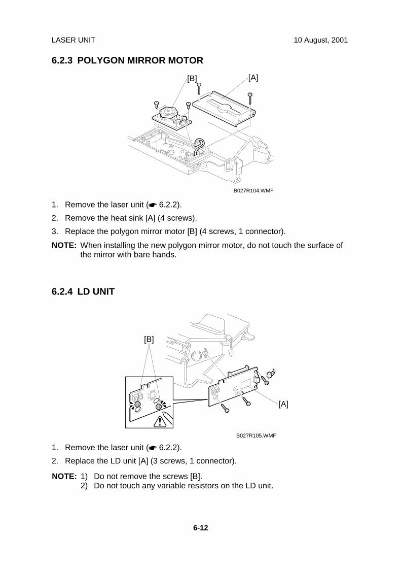
LASER UNIT 10 August, 2001
6-12
6.2.3 POLYGON MIRROR MOTOR
1. Remove the laser unit (☛ 6.2.2).2. Remove the heat sink [A] (4 screws).3. Replace the polygon mirror motor [B] (4 screws, 1 connector).
NOTE: When installing the new polygon mirror motor, do not touch the surface ofthe mirror with bare hands.
6.2.4 LD UNIT
1. Remove the laser unit (☛ 6.2.2).2. Replace the LD unit [A] (3 screws, 1 connector).
NOTE: 1) Do not remove the screws [B].2) Do not touch any variable resistors on the LD unit.
B027R104.WMF
B027R105.WMF
[A][B]
[A]
[B]

10 August, 2001 LASER UNIT
6-13
Rep
lace
men
tA
djus
tmen
t
6.2.5 LASER SYNCHRONIZATION DETECTOR
1. Remove the laser unit (☛ 6.2.2).2. Remove the heat sink [A] (4 screws).3. Remove the laser unit cover [B] (3 screws).4. Remove the bracket [C] (1 screw).5. Replace the laser synchronization detector [D] (1 connector).
B027R106.WMF
B027R107.WMF
[A]
[C]
[D]
[B]

PHOTOCONDUCTOR UNIT (PCU) 10 August, 2001
6-14
6.3 PHOTOCONDUCTOR UNIT (PCU)6.3.1 PCU
1. Open the right cover [A] and front cover [B].2. Pull the PCU [C] out slightly while pushing the release lever [D].
NOTE: Do not touch the drum surface with bare hands.
B027R203.WMF
[A]
[B]
[C]
[D]

10 August, 2001 TRANSFER UNIT
6-15
Rep
lace
men
tA
djus
tmen
t
6.4 TRANSFER UNIT6.4.1 TRANSFER ROLLER UNIT
1. Open the right cover [A].2. Remove the transfer roller unit [B] (1 hook).
NOTE: Do not touch the transfer roller surface.
B027R401.WMF
[A]
[B]
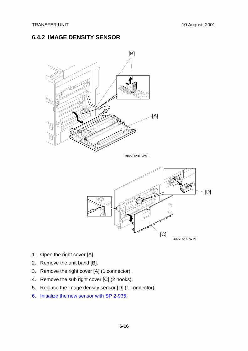
TRANSFER UNIT 10 August, 2001
6-16
6.4.2 IMAGE DENSITY SENSOR
1. Open the right cover [A].2. Remove the unit band [B].3. Remove the right cover [A] (1 connector),4. Remove the sub right cover [C] (2 hooks).5. Replace the image density sensor [D] (1 connector).6. Initialize the new sensor with SP 2-935.
B027R201.WMF
B027R202.WMF
[A]
[C]
[D]
[B]
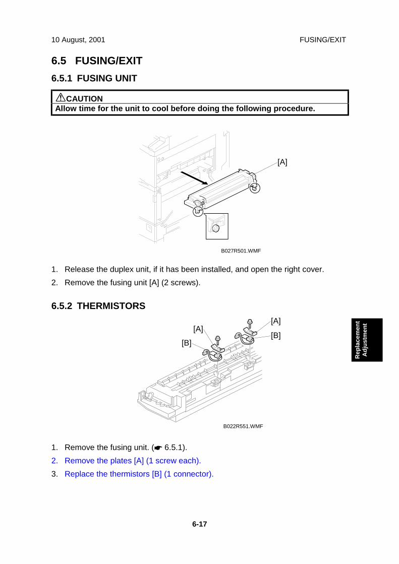
10 August, 2001 FUSING/EXIT
6-17
Rep
lace
men
tA
djus
tmen
t
6.5 FUSING/EXIT6.5.1 FUSING UNIT
!CAUTIONAllow time for the unit to cool before doing the following procedure.
1. Release the duplex unit, if it has been installed, and open the right cover.2. Remove the fusing unit [A] (2 screws).
6.5.2 THERMISTORS
1. Remove the fusing unit. (☛ 6.5.1).2. Remove the plates [A] (1 screw each).3. Replace the thermistors [B] (1 connector).
B027R501.WMF
B022R551.WMF
[A]
[A]
[B][A]
[B]

FUSING/EXIT 10 August, 2001
6-18
6.5.3 THERMOFUSE
1. Remove the fusing unit. (☛ 6.5.1)2. Remove the fusing upper cover [A] (4 screws).3. Remove the pressure springs [B].4. Remove the hot roller stripper bracket [C] (3 screws).
B027R503.WMF
B022R552.WMF
[A]
[B][C]
[B]

10 August, 2001 FUSING/EXIT
6-19
Rep
lace
men
tA
djus
tmen
t
5. Remove the thermostat cover [A] (2 tapping screws).6. Remove the plate [B] (2 screws with spring washer).7. Remove the thermostat holder [C] (3 screws each).8. Replace the thermostats [D].
B022R553.WMF
B022R554.WMF
[A]
[B]
[C][D]
[C][D]
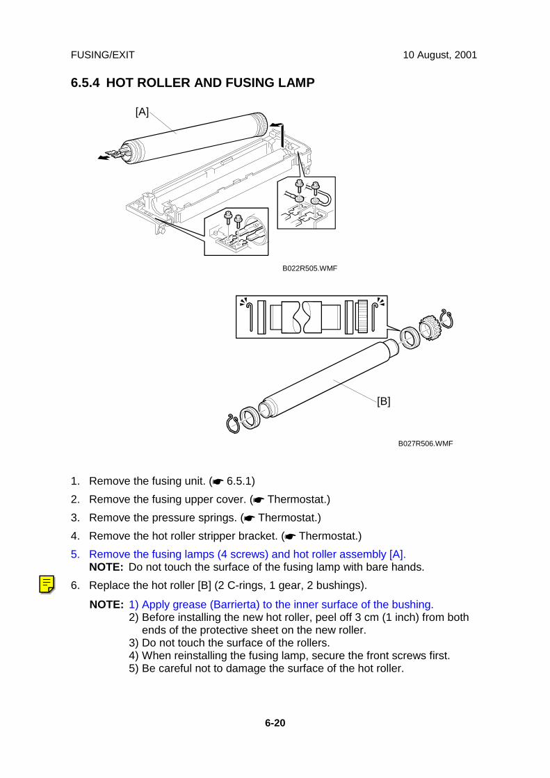
FUSING/EXIT 10 August, 2001
6-20
6.5.4 HOT ROLLER AND FUSING LAMP
1. Remove the fusing unit. (☛ 6.5.1)2. Remove the fusing upper cover. (☛ Thermostat.)3. Remove the pressure springs. (☛ Thermostat.)4. Remove the hot roller stripper bracket. (☛ Thermostat.)5. Remove the fusing lamps (4 screws) and hot roller assembly [A].
NOTE: Do not touch the surface of the fusing lamp with bare hands.6. Replace the hot roller [B] (2 C-rings, 1 gear, 2 bushings).
NOTE: 1) Apply grease (Barrierta) to the inner surface of the bushing.2) Before installing the new hot roller, peel off 3 cm (1 inch) from both
ends of the protective sheet on the new roller.3) Do not touch the surface of the rollers.4) When reinstalling the fusing lamp, secure the front screws first.5) Be careful not to damage the surface of the hot roller.
B027R506.WMF
B022R505.WMF
[B]
[A]
Ricoh Technical Services
RTB 30 Notes for C-ring installation
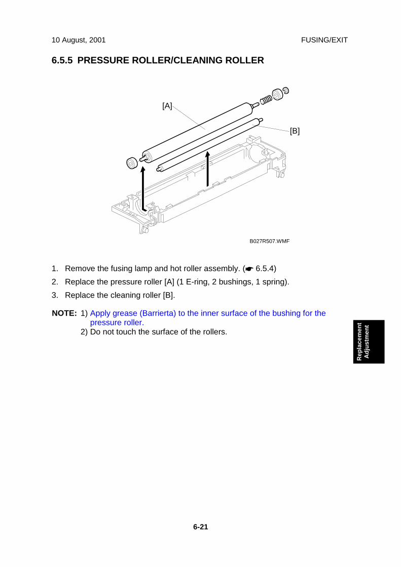
10 August, 2001 FUSING/EXIT
6-21
Rep
lace
men
tA
djus
tmen
t
6.5.5 PRESSURE ROLLER/CLEANING ROLLER
1. Remove the fusing lamp and hot roller assembly. (☛ 6.5.4)2. Replace the pressure roller [A] (1 E-ring, 2 bushings, 1 spring).3. Replace the cleaning roller [B].
NOTE: 1) Apply grease (Barrierta) to the inner surface of the bushing for thepressure roller.
2) Do not touch the surface of the rollers.
B027R507.WMF
[A]
[B]

FUSING/EXIT 10 August, 2001
6-22
6.5.6 PAPER EXIT SENSOR/PAPER OVERFLOW SENSOR
1. Remove the front upper cover [A] (1 screw, 1 peg).2. Remove the exit cover [B].
NOTE: If the optional 1 bin tray unit and/or interchange unit have beeninstalled, remove them.
3. Replace the exit sensor [C] (1 connector).4. Replace the overflow sensor [D] (1 connector).
B027R601.WMF
[A]
[B]
[C]
[D]

10 August, 2001 PAPER FEED
6-23
Rep
lace
men
tA
djus
tmen
t
6.6 PAPER FEED6.6.1 FEED ROLLERS
1. Remove the paper tray [A].2. Pull the lever [B].3. Replace the feed roller [C].
NOTE: Do not touch the roller surface with bare hands.After reinstalling the feed roller, return the lever [A].
B027R723.WMF
[B]
[C]
[A]
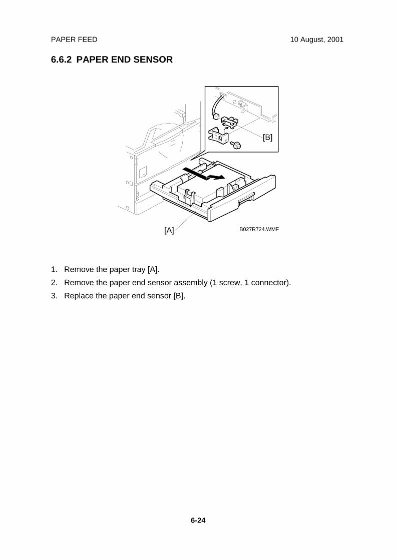
PAPER FEED 10 August, 2001
6-24
6.6.2 PAPER END SENSOR
1. Remove the paper tray [A].2. Remove the paper end sensor assembly (1 screw, 1 connector).3. Replace the paper end sensor [B].
B027R724.WMF[A]
[B]

10 August, 2001 PAPER FEED
6-25
Rep
lace
men
tA
djus
tmen
t
6.6.3 PAPER TRAY LIFT MOTORS
1. Remove the paper tray.2. Remove the connector cover [A] (1 screw) and disconnect the cable.3. Remove the rear cover [B] (4 screws).4. Remove the duplex connector cover [C] (1 screw).5. Remove the lower rear cover [D] (2 screws).6. Replace the paper lift motors [E] (2 screws each, 1 connector each).
B027R705.WMFB027R515.WMF
B027R707.WMF
[A]
[B]
[C]
[D]
[E]
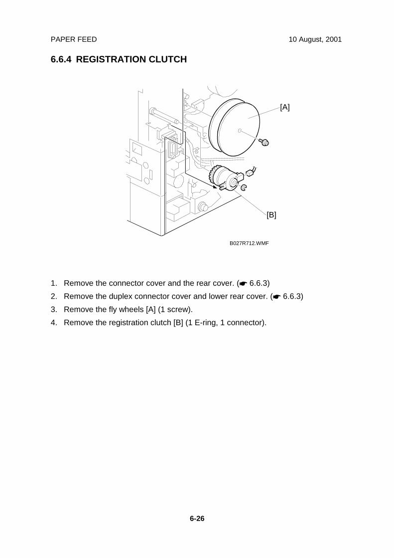
PAPER FEED 10 August, 2001
6-26
6.6.4 REGISTRATION CLUTCH
1. Remove the connector cover and the rear cover. (☛ 6.6.3)2. Remove the duplex connector cover and lower rear cover. (☛ 6.6.3)3. Remove the fly wheels [A] (1 screw).4. Remove the registration clutch [B] (1 E-ring, 1 connector).
B027R712.WMF
[A]
[B]

10 August, 2001 PAPER FEED
6-27
Rep
lace
men
tA
djus
tmen
t
6.6.5 PAPER FEED CLUTCHES
Lower Paper Feed Clutch
1. Remove the rear cover. (☛ 6.6.3)2. Remove the lower rear cover. (☛ 6.6.3)3. Replace the lower paper feed clutch [A] (1 connector).
Upper Paper Feed Clutch.
4. Disconnect the connectors [B] for the SBCU board as shown (14 connectors).5. Remove 4 screws [C] securing the SBCU board bracket then swing down the
I/O board bracket [D].6. Remove the bracket [E] (1 screw).7. Replace the upper paper feed clutch [F] (1 connector).
B027R713.WMF
B027R709.WMF
B027R715.WMF
[E]
[A]
[F]
[B]
[C]
[D]
[C]

PAPER FEED 10 August, 2001
6-28
6.6.6 RELAY CLUTCHES
1. Remove the optional duplex unit and/or by-pass tray unit if they have beeninstalled.
2. Remove the rear cover and lower rear cover. (☛ 6.6.3)3. Remove the lower right cover [A] (2 screws).4. Remove the scanner right cover. (☛ 6.1.2)5. Remove the right cover [B] (4 screws).6. Swing down the I/O board bracket. (☛ 6.6.5)7. Remove the connector bracket [C] (2 screws).8. Replace the upper relay clutch [D] (1 connector).9. Remove the right back cover [E] (1 screw).10. Replace the lower relay clutch [F] (1 connector).
B027R717.WMF
B027R714.WMF
B027R716.WMF
[A]
[B]
[C]
[D]
[E][F]
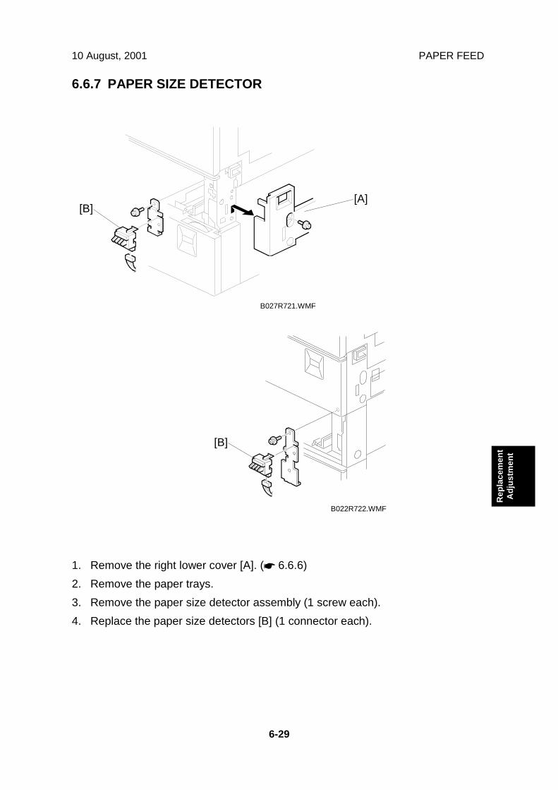
10 August, 2001 PAPER FEED
6-29
Rep
lace
men
tA
djus
tmen
t
6.6.7 PAPER SIZE DETECTOR
1. Remove the right lower cover [A]. (☛ 6.6.6)2. Remove the paper trays.3. Remove the paper size detector assembly (1 screw each).4. Replace the paper size detectors [B] (1 connector each).
B027R721.WMF
B022R722.WMF
[A]
[B]
[B]

PAPER FEED 10 August, 2001
6-30
6.6.8 REGISTRATION SENSOR
1. Remove the right cover. (☛ 6.4.2)2. Remove the registration guide plate [A] (2 screws).3. Remove the paper support roller [B] (2 snap rings, 2 bushings).4. Remove the sensor bracket [C] (1 screw).5. Replace the registration sensor [D] (1 connector).
B027R718.WMF
[A]
[C]
[D]
[B]
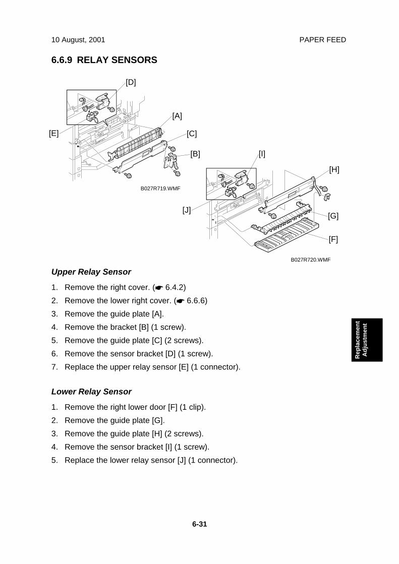
10 August, 2001 PAPER FEED
6-31
Rep
lace
men
tA
djus
tmen
t
6.6.9 RELAY SENSORS
Upper Relay Sensor
1. Remove the right cover. (☛ 6.4.2)2. Remove the lower right cover. (☛ 6.6.6)3. Remove the guide plate [A].4. Remove the bracket [B] (1 screw).5. Remove the guide plate [C] (2 screws).6. Remove the sensor bracket [D] (1 screw).7. Replace the upper relay sensor [E] (1 connector).
Lower Relay Sensor
1. Remove the right lower door [F] (1 clip).2. Remove the guide plate [G].3. Remove the guide plate [H] (2 screws).4. Remove the sensor bracket [I] (1 screw).5. Replace the lower relay sensor [J] (1 connector).
B027R719.WMF
B027R720.WMF
[A]
[B]
[C]
[D]
[E]
[F]
[G]
[H]
[I]
[J]

PCBS AND OTHER ITEMS 10 August, 2001
6-32
6.7 PCBS AND OTHER ITEMS6.7.1 CONTROLLER BOARD
1. Remove the rear cover. (☛ 6.6.3)2. Remove the optional finisher if it has been installed.3. Remove the application cover [A] (1 screw).4. Remove the shield plate [B] (8 screws) or the optional fax unit if it has been
installed.5. Remove the controller board [C] (2 connectors, 8 screws).6. Remove the NVRAM [D], and DIMM (printer/scanner, memory, etc) from the
old controller board and put them on the new controller board.
B022R951.WMF
B022R952.WMF
[D]
[C]
[A]
[B]

10 August, 2001 PCBS AND OTHER ITEMS
6-33
Rep
lace
men
tA
djus
tmen
t
6.7.2 SBCU BOARD
1. Remove the rear cover. (☛ 6.6.3)2. Remove the SBCU board [A] (All connectors, 6 screws).
6.7.3 POWER PACK
1. Remove the rear cover. (☛ 6.6.3)2. Swing down the I/O board bracket. (☛ 6.6.5)3. Remove the power pack [A] (5 connectors, 3 screws).
B027R708.WMF
B027R710.WMF
[A]
[A]
Ricoh Technical Services
RTB 9 Notes about dip switches RTB 24 China model only: Notes about dip switches and about models made in the SRF factory in China
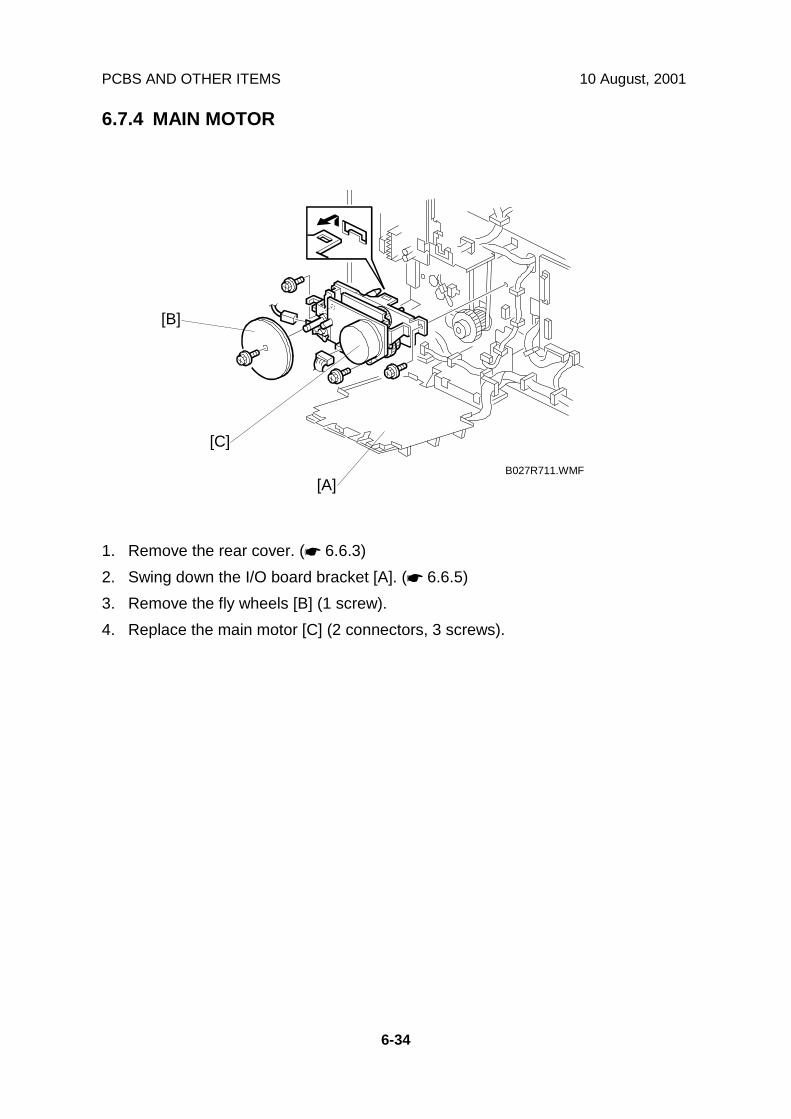
PCBS AND OTHER ITEMS 10 August, 2001
6-34
6.7.4 MAIN MOTOR
1. Remove the rear cover. (☛ 6.6.3)2. Swing down the I/O board bracket [A]. (☛ 6.6.5)3. Remove the fly wheels [B] (1 screw).4. Replace the main motor [C] (2 connectors, 3 screws).
B027R711.WMF
[B]
[A]
[C]

10 August, 2001 PCBS AND OTHER ITEMS
6-35
Rep
lace
men
tA
djus
tmen
t
6.7.5 PSU
1. Remove the optional finisher if it has been installed.2. Remove the application cover [A] (1 screw).3. Remove the left cover [B] (6 screws).4. 220 V machine only: Remove the transformer [C] (1 screw).5. Remove the PSU [D] (all connectors, 6 screws, 1 clip).
B027R701.WMF
B022R702.WMF
[A]
[B]
[D]
[C]

COPY ADJUSTMENTS: PRINTING/SCANNING 10 August, 2001
6-36
6.8 COPY ADJUSTMENTS: PRINTING/SCANNING
NOTE: 1) You need to perform these adjustment(s) after replacing any of thefollowing parts:• Scanner Wire• Lens Block/SBU Assembly• Scanner Drive Motor• Polygon Mirror Motor• Paper Side Fence• Memory All Clear
2) For more details about accessing SP modes, refer to section 4.
6.8.1 PRINTING
NOTE: 1) Make sure the paper is installed correctly in each paper tray before youstart these adjustments.
2) Use the Trimming Area Pattern (SP2-902-3, No.10) to print the testpattern for the following procedures.
3) Set SP 2-902-3 to 0 again after completing these printing adjustments.
Registration - Leading Edge/Side-to-Side
1. Check the leading edge registration for each paper feed station, and adjustthem using SP1-001.
2. Check the side-to-side registration for each paper feed station, and adjust themusing SP1-002.
Tray SP mode SpecificationAny paper tray SP1-001-1By-pass feed SP1-001-2Duplex SP1-001-3
3 ± 2 mm
1st paper feed SP1-002-12nd paper feed SP1-002-23rd paper feed (OptionalPFU tray 1), or LCT SP1-002-3 2 ± 1.5 mm
4th paper feed (OptionalPFU tray 2) SP1-002-4
By-pass feed SP1-002-5Duplex, side 2 SP1-002-6
A: Leading Edge RegistrationB: Side-to-side Registration
_
^
B027R508.WMF
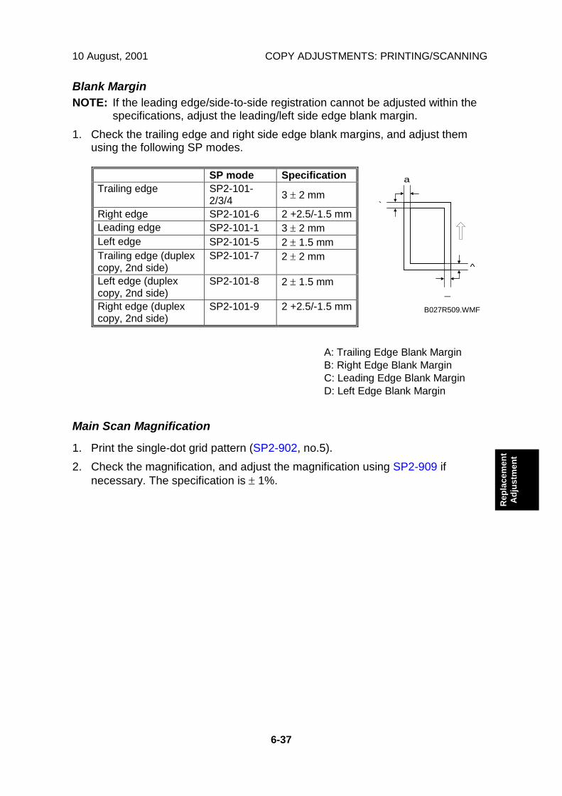
10 August, 2001 COPY ADJUSTMENTS: PRINTING/SCANNING
6-37
Rep
lace
men
tA
djus
tmen
t
Blank MarginNOTE: If the leading edge/side-to-side registration cannot be adjusted within the
specifications, adjust the leading/left side edge blank margin.1. Check the trailing edge and right side edge blank margins, and adjust them
using the following SP modes.
SP mode SpecificationTrailing edge SP2-101-
2/3/4 3 ± 2 mm
Right edge SP2-101-6 2 +2.5/-1.5 mmLeading edge SP2-101-1 3 ± 2 mmLeft edge SP2-101-5 2 ± 1.5 mmTrailing edge (duplexcopy, 2nd side)
SP2-101-7 2 ± 2 mm
Left edge (duplexcopy, 2nd side)
SP2-101-8 2 ± 1.5 mm
Right edge (duplexcopy, 2nd side)
SP2-101-9 2 +2.5/-1.5 mm
A: Trailing Edge Blank MarginB: Right Edge Blank MarginC: Leading Edge Blank MarginD: Left Edge Blank Margin
Main Scan Magnification
1. Print the single-dot grid pattern (SP2-902, no.5).2. Check the magnification, and adjust the magnification using SP2-909 if
necessary. The specification is ± 1%.
a
`
_
^
B027R509.WMF

COPY ADJUSTMENTS: PRINTING/SCANNING 10 August, 2001
6-38
Parallelogram Image AdjustmentDo the following procedure if a parallelogram is printed while adjusting the printingregistration or the printing margin using a trimming area pattern.NOTE: The following procedure should be done after adjusting the side-to-side
registration for each paper tray station.
1. Check whether the trimming area pattern (SP2-902, No.10) is printed as aparallelogram, as shown. If it is, do the following.
2. Remove the laser unit [A] (☛ 6.2).3. Remove the bracket [B] (2 screws).4. Install the adjusting cam [C] (P/N: A2309003).5. Secure the adjustment bracket [D] (P/N A2679002) using the screw which was
used for bracket [B]. However, do not tighten the screws at this time.6. Adjusts the laser unit position by turning the adjusting cam. (Refer to the above
illustration for the relationship between the image and the cam rotationdirection).
7. Tighten the adjustment bracket.8. Print the trimming area pattern to check the image. If it is still unsatisfactory,
repeat steps 4 to 8.
B027R013.WMF
Turnclockwise
Turncounterclockwise
B027R510.WMF
[A]
[B]
[C] [D]

10 August, 2001 COPY ADJUSTMENTS: PRINTING/SCANNING
6-39
Rep
lace
men
tA
djus
tmen
t
6.8.2 SCANNING
NOTE: 1) Before doing the following scanner adjustments, perform or check theprinting registration/side-to-side adjustment and the blank marginadjustment.
2) Use an S5S test chart to perform the following adjustments.
Registration: Platen Mode
1. Place the test chart on the exposure glass and make a copy from one of thefeed stations.
2. Check the leading edge and side-to-side registration, and adjust them using thefollowing SP modes if necessary.
SP modeLeading Edge SP4-010Side-to-side SP4-011
A: Leading Edge RegistrationB: Side-to-side Registration
MagnificationNOTE: Use an S5S test chart to perform the following adjustment.
A: Sub Scan MagnificationB: Main Scan magnification
1. Place the test chart on the exposure glass and make a copy from one of thefeed stations.
2. Check the magnification ratio, and adjust it using the following SP mode ifnecessary. The specification is ±1%.
SP modeSub Scan Magnification SP4-009Main Scan Magnification SP4-008
_
^
B027R511.WMF
A
B
B027R500.WMF
Ricoh Technical Services
Incorrect 4-008 should be sub-scan, and 4-009 should be main scan.
Ricoh Technical Services
COPY ADJUSTMENTS: PRINTING/SCANNING 10 August, 2001
6-40
Standard White Density Adjustment
This adjusts the standard white density level.Perform this adjustment in any of the following conditions:• After replacing the standard white plate.• After replacing the NVRAM on the controller board. (If only controller board is
replaced, this adjustment is not necessary, as the NVRAM from the old controllerboard is put on the new controller board.)
• After performing a memory all clear (SP5-801).
Procedure:
1. Place 10 sheets of new A4 sideways (do not use any recycled paper) or A3paper on the exposure glass and close the platen cover or the ADF.
2. Enter SP 4-428 and select “1: Yes”. The standard white density is automaticallyadjusted.
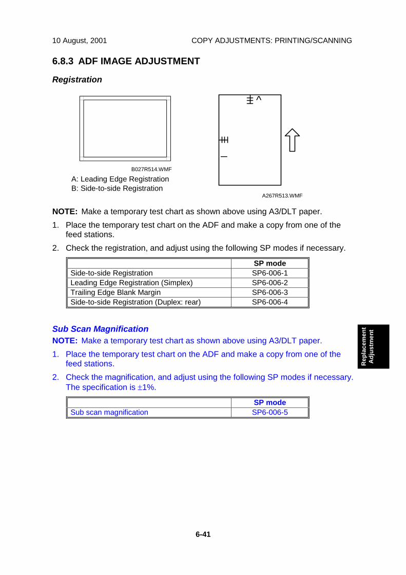
10 August, 2001 COPY ADJUSTMENTS: PRINTING/SCANNING
6-41
Rep
lace
men
tA
djus
tmen
t
6.8.3 ADF IMAGE ADJUSTMENT
Registration
A: Leading Edge RegistrationB: Side-to-side Registration
NOTE: Make a temporary test chart as shown above using A3/DLT paper.1. Place the temporary test chart on the ADF and make a copy from one of the
feed stations.2. Check the registration, and adjust using the following SP modes if necessary.
SP modeSide-to-side Registration SP6-006-1Leading Edge Registration (Simplex) SP6-006-2Trailing Edge Blank Margin SP6-006-3Side-to-side Registration (Duplex: rear) SP6-006-4
Sub Scan MagnificationNOTE: Make a temporary test chart as shown above using A3/DLT paper.1. Place the temporary test chart on the ADF and make a copy from one of the
feed stations.2. Check the magnification, and adjust using the following SP modes if necessary.
The specification is ±1%.
SP modeSub scan magnification SP6-006-5
B027R514.WMF
_
^
A267R513.WMF
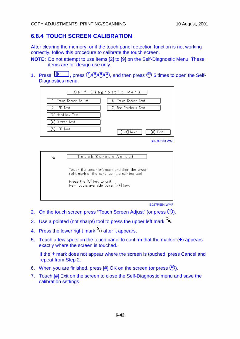
COPY ADJUSTMENTS: PRINTING/SCANNING 10 August, 2001
6-42
6.8.4 TOUCH SCREEN CALIBRATION
After clearing the memory, or if the touch panel detection function is not workingcorrectly, follow this procedure to calibrate the touch screen.NOTE: Do not attempt to use items [2] to [9] on the Self-Diagnostic Menu. These
items are for design use only.
1. Press ", press #$$%, and then press & 5 times to open the Self-Diagnostics menu.
2. On the touch screen press “Touch Screen Adjust” (or press #).
3. Use a pointed (not sharp!) tool to press the upper left mark .
4. Press the lower right mark after it appears.
5. Touch a few spots on the touch panel to confirm that the marker (+) appearsexactly where the screen is touched.
If the + mark does not appear where the screen is touched, press Cancel andrepeat from Step 2.
6. When you are finished, press [#] OK on the screen (or press ').7. Touch [#] Exit on the screen to close the Self-Diagnostic menu and save the
calibration settings.
B027R533.WMF
B027R554.WMF

10 August, 2001 SERVICE CALL CONDITIONS
7-1
Trou
ble-
shoo
ting
7. TROUBLESHOOTING!CAUTIONNever turn off the main power switch when the power LED is lit or flashing.To avoid damaging the hard disk or memory, press the operation powerswitch to switch the power off, wait for the power LED to go off, and thenswitch the main power switch off.
NOTE: The main power LED ( ) lights or flashes while the platen cover orARDF is open, while the main machine is communicating with a facsimileor the network server, or while the machine is accessing the hard disk ormemory for reading or writing data.
7.1 SERVICE CALL CONDITIONS7.1.1 SUMMARY
There are 4 levels of service call conditions.Level Definition Reset Procedure
A
To prevent damage to the machine, the mainmachine cannot be operated until the SC hasbeen reset by a service representative (see thenote below).
Enter SP mode, and then turnthe main power switch off andon.
B
SCs that disable only the features that use thedefective item. Although these SCs are not shownto the user under normal conditions, they aredisplayed on the operation panel only when thedefective feature is selected.
Turn the operation switch ormain switch off and on.
C The SC history is updated. The machine can beoperated as usual.
The SC will not be displayed.Only the SC history is updated.
DTurning the main switch off then on resets SCsdisplayed on the operation panel. These are re-displayed if the error occurs again.
Turn the operation switch offand on.
NOTE: 1) If the problem concerns electrical circuit boards, first disconnect thenreconnect the connectors before replacing the PCBs.
2) If the problem concerns a motor lock, first check the mechanical loadbefore replacing motors or sensors.

SERVICE CALL CONDITIONS 10 August, 2001
7-2
7.1.2 SC CODE DESCRIPTIONSCode No. Symptom Possible Cause
Exposure lamp error101 BThe standard white level was notdetected properly when scanning thewhite plate.
• Exposure lamp defective• Lamp stabilizer defective• Exposure lamp connector defective• Standard white plate dirty• Scanner mirror or scanner lens out of
position or dirty• SBU defective
Scanner home position error 1120 DThe scanner home position sensordoes not detect the on condition duringinitialization or copying.
• Scanner drive motor defective• Scanner motor defective• Harness between SBCU and
scanner drive motor disconnected• Harness between SBCU and
scanner drive motor power sourcedisconnected
• Scanner HP sensor defective• Harness between SBCU and HP
sensor disconnected• Scanner wire, timing belt, pulley, or
carriage defectiveScanner home position error 2121 DThe scanner home position sensordoes not detect the off condition duringinitialization.
• SIB or scanner drive motor defective• Scanner motor defective• Harness between SBCU and
scanner drive motor disconnected• Harness between SBCU and
scanner drive motor power sourcedisconnected
• Scanner HP sensor defective• Harness between SBCU and HP
sensor disconnected• Scanner wire, timing belt, pulley, or
carriage defectiveSBU connection error144 BThe IPU does not detect the SBUconnection signal.
Cable between SBU and IPU boarddisconnected.
Automatic SBU adjustment error192 BAn error is detected during automaticSBU adjustment (SP4-428)
• SBU defective• SBCU board defective• Exposure lamp stabilizer defective• Exposure lamp defective• Dirty white plate
Image transfer error193 BThe IPU board does not finish within 1minute after the image data has beentransferred to the controller board.
• IPU board defective• Controller board defective• Video controller defective
DFGATE assert error195 BThe DFGATE signal does not assertwithin 30 seconds after the original hasbeen scanned.
• ADF interface cable defective• SBCU board defective• Mismatched firmware between the
SBCU board and ADFDFGATE negate error196 BThe DFGATE signal does not negatewithin 1 minute after the DFGATE hasbeen asserted.
• ADF interface cable defective• SBCU board defective• Mismatched firmware between the
SBCU board and ADF
Ricoh Technical Services
RTB 6 SC 122, 123 added
Ricoh Technical Services
RTB 6 SC 191 added RTB 24 SC191 may appear if SBCU dip switches are not set correctly (China only)

10 August, 2001 SERVICE CALL CONDITIONS
7-3
Trou
ble-
shoo
ting
Code No. Symptom Possible CauseDFGATE error197 BThe DFGEATE signal has already beenasserted at the original scan.
• ADF interface cable defective• SBCU board defective• Mismatched firmware between the
SBCU board and ADFMemory address error198 BThe IPU board does not receive thememory address from the controllerboard.
• Mismatched firmware between theSBCU board and controller board
• Controller defective• SBCU defective• IPU board defective
DF scanning finish error199 BThe original does not finish scanningwith in 1 minute
• ADF interface cable defective• SBCU board defective• Mismatched firmware between the
SBCU board and ADFCharge roller current leak302 BA charge roller current leak signal isdetected.
• Charge roller damaged• Charge high voltage supply board
defective• Poor connection of the PCU
Polygon motor error320 BThe polygon motor does not reach itsoperating speed within 10 seconds afterthe polygon motor on signal, or the locksignal is not detected for more than 200ms continuously during operation.
• Polygon mirror motor defective• Poor connection between the
polygon mirror motor driver and theSBCU board
• SBCU board defective
Laser synchronization error322 BThe main scan synchronization detectorboard cannot detect the lasersynchronization signal for more than 10consecutive 50 ms intervals.
• Poor connection between the lasersynchronization detector board andthe SBCU board
• Laser synchronization detector boardout of position
• Laser synchronization detector boarddefective
• SBCU board defective• LD unit defective
LD drive current over323 BThe LD drive board applies more than100 mA to the LD.
• LD unit defective (not enough power,due to aging)
• Poor connection between the LD unitand the SBCU board
• SBCU board defectiveTD sensor error390 DThe TD sensor outputs less than 0.5Vor more than 4.0V 10 timesconsecutively during copying.
• TD sensor abnormal• Poor connection of the PCU
Development bias leak391 BA development bias leak signal isdetected.
• Poor connection of the PCU• High voltage supply board defective
TD sensor initial setting error392 BTD sensor output voltage falls out of theadjustment range (2.0 ±<> 0.2 V) afterthe TD sensor initial setting has beenfinished.
• Someone forgot to remove the tonerseal of the PCU
• ID sensor defective• TD sensor abnormal• Drum does not turn• Development roller does not turn• Poor connection of the PCU
Ricoh Technical Services
RTB 15 SC 355
Ricoh Technical Services
RTB 23 SC390

SERVICE CALL CONDITIONS 10 August, 2001
7-4
Code No. Symptom Possible Cause401 B Transfer roller leak error 1
Transfer roller leak error 2402 BA transfer roller current leak signal isdetected.The current feedback signal for thetransfer roller is not detected.
• High voltage supply board defective• Poor connection of the PCU• Transfer/separation unit set
incorrectly• Transfer roller damaged
Separation bias leak error411 BA separation bias leak signal isdetected.
• High voltage supply board defective• Poor connection of the PCU• Discharge plate defective
Toner supply motor leak error490 BOver 1 A supplied to the toner supplymotor for longer than 200 ms.
Toner supply motor defective
Main motor lock500 BA main motor lock signal is not detectedfor more than 500 ms after the mainmotor starts to rotate, or the lock signalis not detected for more than 500 msduring rotation after the last signal.
• Too much load on the drivemechanism
• Main motor defective
501 B 1st paper tray lift motor malfunction502 B 2nd paper tray lift motor malfunction503 B 3rd paper tray lift motor malfunction
(optional paper tray unit)4th paper tray lift motor malfunction(optional paper tray unit)
504 B
The paper lift sensor is not activatedafter the tray lift motor has been on for18 seconds.
• Paper lift sensor defective• Tray lift motor defective• Too much load on the drive
mechanism• Poor tray lift motor connection
Paper tray motor lock (optional papertray unit)
506 B
A motor lock signal is not detected formore than 1.5 s or the lock signal is notdetected for more than 1.0 s duringrotation.
• Paper tray unit motor defective• Too much load on the drive
mechanism
Rear fence drive error (optional LCT)508 BThe return position sensor is notactivated after the rear fence drivemotor has been on to lower the tandemtray for 8 seconds.
• Rear fence motor defective• Return position sensor defective• Too much load on the drive
mechanism
Side fence drive error (optional LCT)509 BThe side fence positioning sensor is notactivated for more 3 seconds when thepaper stack in the left tray is moved tothe right tray.The side fence close sensor is notactivated for more 3 seconds aftermoving the paper stack to the right tray.
• Side fence motor defective• Side fence position sensor defective• Side fence close sensor defective• Too much load on the drive
mechanism
LCT lower limit error510 BThe lower limit sensor does not activatewithin 8 seconds after the tray has beenlowered.
• Tray lift motor defective• Poor connection of the tray lift motor• Lower limit sensor defective• Too much load on the drive
mechanism
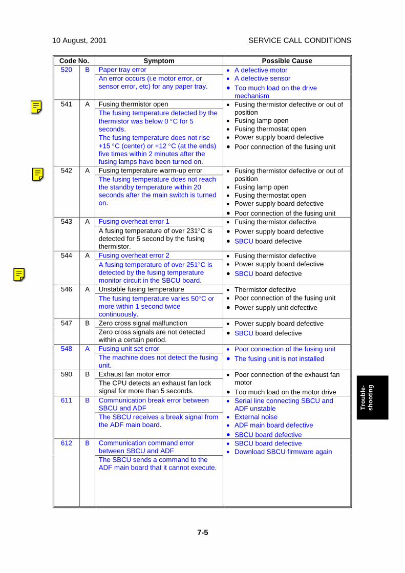
10 August, 2001 SERVICE CALL CONDITIONS
7-5
Trou
ble-
shoo
ting
Code No. Symptom Possible CausePaper tray error520 BAn error occurs (i.e motor error, orsensor error, etc) for any paper tray.
• A defective motor• A defective sensor• Too much load on the drive
mechanismFusing thermistor open541 AThe fusing temperature detected by thethermistor was below 0 °C for 5seconds.The fusing temperature does not rise+15 °C (center) or +12 °C (at the ends)five times within 2 minutes after thefusing lamps have been turned on.
• Fusing thermistor defective or out ofposition
• Fusing lamp open• Fusing thermostat open• Power supply board defective• Poor connection of the fusing unit
Fusing temperature warm-up error542 AThe fusing temperature does not reachthe standby temperature within 20seconds after the main switch is turnedon.
• Fusing thermistor defective or out ofposition
• Fusing lamp open• Fusing thermostat open• Power supply board defective• Poor connection of the fusing unit
Fusing overheat error 1543 AA fusing temperature of over 231°C isdetected for 5 second by the fusingthermistor.
• Fusing thermistor defective• Power supply board defective• SBCU board defective
Fusing overheat error 2544 AA fusing temperature of over 251°C isdetected by the fusing temperaturemonitor circuit in the SBCU board.
• Fusing thermistor defective• Power supply board defective• SBCU board defective
Unstable fusing temperature546 AThe fusing temperature varies 50°C ormore within 1 second twicecontinuously.
• Thermistor defective• Poor connection of the fusing unit• Power supply unit defective
Zero cross signal malfunction547 BZero cross signals are not detectedwithin a certain period.
• Power supply board defective• SBCU board defective
Fusing unit set error548 AThe machine does not detect the fusingunit.
• Poor connection of the fusing unit• The fusing unit is not installed
Exhaust fan motor error590 BThe CPU detects an exhaust fan locksignal for more than 5 seconds.
• Poor connection of the exhaust fanmotor
• Too much load on the motor driveCommunication break error betweenSBCU and ADF
611 B
The SBCU receives a break signal fromthe ADF main board.
• Serial line connecting SBCU andADF unstable
• External noise• ADF main board defective• SBCU board defective
Communication command errorbetween SBCU and ADF
612 B
The SBCU sends a command to theADF main board that it cannot execute.
• SBCU board defective• Download SBCU firmware again
Ricoh Technical Services
RTB 11a SC542 - SP added to prevent this error
Ricoh Technical Services
SC541 RTB 11c
Ricoh Technical Services
RTB 20 SC545

SERVICE CALL CONDITIONS 10 August, 2001
7-6
Code No. Symptom Possible CauseCommunication timeout error betweenSBCU and finisher
620 B
The SBCU cannot receive a responsewithin 100 ms after 3 attempts aftersending data to the finisher.
• Serial line connecting SBCU andfinisher unstable
• External noise• SBCU board and finisher main board
connection defective or loose• Finisher main board defective• SBCU board defective
Communication timeout error betweenSBCU and finisher
621 B
A break (low) signal was received fromthe finisher.
• Serial line connecting SBCU andfinisher unstable
• External noise
Communication failure with CSS (RSS)630 CThe communication from the copierwas detected as abnormal at the CSScenter. This error occurs when theacknowledge signal from the LADPdoes not complete normally.
• Occurred with an SC call, CC call,supply management call, user call, orCE call.
• Timeout while no response from theLADP, and abnormal signal on theRS-485 line between PI and LADP.
SBCU control data transfer checksumerror
640 C
A sampling of control data sent from theSBCU to the controller reveals achecksum error. Only the logging countis performed.
• Controller board defective• External noise• SBCU board defective
SBCU control data transfer abnormal641 CA sampling of the control data sent fromthe SBCU reveals an abnormality.
• Controller board defective• External noise• SBCU board defective
Communication timeout error betweenSBCU and duplex unit
650 B
The SBCU cannot receive a responsewithin 1 second from the duplex unit.
• Serial line connecting SBCU andduplex unit unstable
• External noise• SBCU board and duplex main board
connection defective or loose• Duplex main board defective• SBCU board defective
Engine response error670 DAfter powering on the machine, aresponse is not received from theengine within 30 seconds.
• SBCU installed incorrectly• SBCU defective• Controller board defective
Controller-to-operation panelcommunication error at startup
672 D
After powering on the machine, thecommunication circuit between thecontroller and the operation panel is notopened, or communication withcontroller is interrupted after a normalstartup.
• Controller stall• Controller board installed incorrectly• Controller board defective• Operation panel connector loose or
defective
Finisher jogger motor error (500-sheetfinisher)
720 B
The finisher jogger H.P sensor remainsde-activated for a certain time whenreturning to home position.The finisher jogger H.P sensor remainsactivated for a certain time whenmoving away from home position.
• Jogger H.P sensor defective• Jogger motor defective
Ricoh Technical Services
SC620 RTB 28

10 August, 2001 SERVICE CALL CONDITIONS
7-7
Trou
ble-
shoo
ting
Code No. Symptom Possible CauseFinisher jogger motor error (1000-sheetfinisher)
722 B
The finisher jogger H.P sensor remainsde-activated for a certain time whenreturning to home position.The finisher jogger H.P sensor remainsactivated for a certain time whenmoving away from home position.
• Jogger H.P sensor defective• Jogger motor defective
Finisher staple hammer motor error(1000-sheet finisher)
724 B
Stapling does not finish within 600 msafter the staple hammer motor turnedon.
• Staple jam• Stapler overload caused by trying to
staple too many sheets• Staple hammer motor defective
Finisher stack feed-out motor error(1000-sheet finisher)
725 B
The stack feed-out belt H.P sensordoes not activate within a certain timeafter the stack feed-out motor turnedon.
• Stack feed-out H.P sensor defective• Stack feed-out motor defective
Finisher lift motor error (1000-sheetfinisher)
726 B
The stack height sensor does notactivate within a certain time after theshift tray lift motor turned on.
• Shift tray lift motor defective• Stack height sensor defective
Finisher staple hammer motor error(500-sheet finisher)
727 B
Stapling does not finish within a certaintime after staple hammer motor turnedon.
• Staple jam• Stapler overload caused by trying to
staple too many sheets• Staple hammer motor defective
Finisher paper stack height error (500-sheet finisher)
728 B
The stack height detection lever doesnot return to its home position beforegoing to detect the stack height.
• Stack height lever solenoid defective• Stack height sensor defective• Lever sensor defective• Main control board defective
Finisher stapler motor error (1000-sheetfinisher)
730 B
The stapler does not return to its homeposition within a certain time after thestapler motor turned on.The stapler H.P sensor does notactivate within a certain time after thestapler motor turned on.
• Stapler motor defective• Stapler H.P sensor defective• Poor stapler motor connection
Output tray motor error (500-sheetfinisher)Exit guide plate motor error (1000-sheetfinisher)
731 B
The tray upper limit sensor does notactivate within a certain time after theshift motor turned on. (500-sheetfinisher)The exit guide plate open sensor or exitguide plate HP sensor does not activatewithin a certain time after the exit guideplate motor turned on. (1000-sheetfinisher)
500-sheet finisher• Output tray motor defective• Tray upper limit sensor defective
1000-sheet finisher• Exit guide plate motor defective• Exit guide plate HP sensor defective• Exit guide plate open sensor
defective

SERVICE CALL CONDITIONS 10 August, 2001
7-8
Code No. Symptom Possible CauseFinisher shift motor error (1000-sheetfinisher)
732 B
Roller shift does not finish within acertain time after the shift motor turnedon.
• Shift motor defective• Shift tray HP sensor defective
Bridge communication error791 BThe SBCU cannot communicate withthe bridge unit properly when thefinisher is installed.
• Poor connection between the mainmachine and bridge unit
• SBCU board defective
Finisher connection error792 BThe SBCU cannot communicate withthe finisher properly when the bridgeunit is installed.
• Poor connection between the finisherand bridge unit
• SBCU board defective
Interchange communication error793 BThe SBCU cannot communicate withthe interchange unit properly when theduplex unit is installed.
• Poor connection between theinterchange unit and main machine
• SBCU board defective
Startup without video output end error(K)
800 D
Video transfer to the engine is started,but the engine did not issue a videotransmission end command within thespecified time.
Controller board defective
Startup without video input end (K)804 DA video transmission was requestedfrom the scanner, but the scanner didnot issue a video transmission endcommand within the specified time.
Controller board defective
Watchdog error818 DThe CPU does not access thewatchdog register within a certain time.
• Controller board defective• Software malfunction – download
controller firmware againKernel mismatch error819 DSoftware bug
Download controller firmware again
Self-Diagnostic Error: CPU820 DThe central processing unit returned anerror during the self-diagnostic test.
• Controller board defective• Download controller firmware again
Self-Diagnostic Error: ASIC821 DThe ASIC returned an error during theself-diagnostic test because the ASICand CPU timer interrupts werecompared and determined to be out ofrange.
Controller board defective
Self-Diagnostic Error: HDD822 DThe hard disk drive returned an errorduring the self-diagnostic test.
• HDD defective• HDD connector defective• Controller board defective
Self-diagnostic Error: NIB823 DThe network interface board returnedan error during the self-diagnostic test.
• Network interface board defective• Controller board defective
Self-diagnostic Error: NVRAM824 DThe resident non-volatile RAM returnedan error during the self-diagnostic test.
• Replace the NVRAM on thecontroller board
• Replace the controller board
Ricoh Technical Services
RTB 11, 11e SC819
Ricoh Technical Services
RTB 11 SC792 level changed
Ricoh Technical Services
RTB 15 SC 770
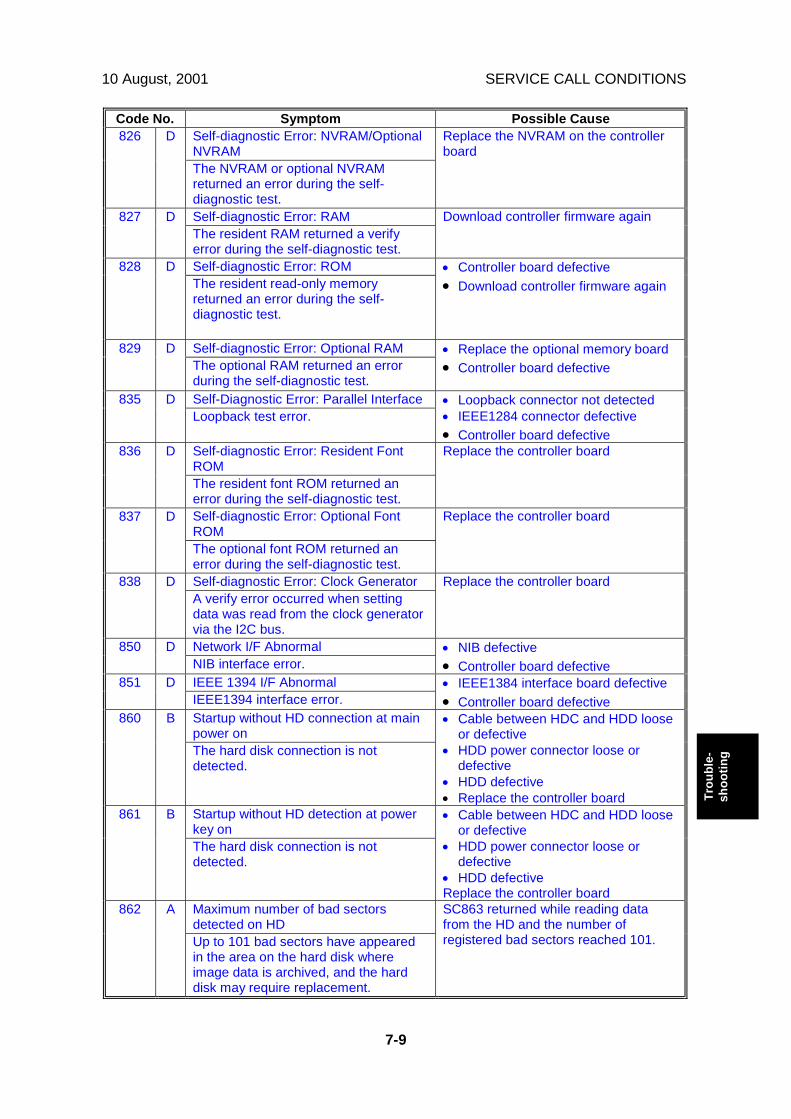
10 August, 2001 SERVICE CALL CONDITIONS
7-9
Trou
ble-
shoo
ting
Code No. Symptom Possible CauseSelf-diagnostic Error: NVRAM/OptionalNVRAM
826 D
The NVRAM or optional NVRAMreturned an error during the self-diagnostic test.
Replace the NVRAM on the controllerboard
Self-diagnostic Error: RAM827 DThe resident RAM returned a verifyerror during the self-diagnostic test.
Download controller firmware again
Self-diagnostic Error: ROM828 DThe resident read-only memoryreturned an error during the self-diagnostic test.
• Controller board defective• Download controller firmware again
Self-diagnostic Error: Optional RAM829 DThe optional RAM returned an errorduring the self-diagnostic test.
• Replace the optional memory board• Controller board defective
Self-Diagnostic Error: Parallel Interface835 DLoopback test error.
• Loopback connector not detected• IEEE1284 connector defective• Controller board defective
Self-diagnostic Error: Resident FontROM
836 D
The resident font ROM returned anerror during the self-diagnostic test.
Replace the controller board
Self-diagnostic Error: Optional FontROM
837 D
The optional font ROM returned anerror during the self-diagnostic test.
Replace the controller board
Self-diagnostic Error: Clock Generator838 DA verify error occurred when settingdata was read from the clock generatorvia the I2C bus.
Replace the controller board
Network I/F Abnormal850 DNIB interface error.
• NIB defective• Controller board defective
IEEE 1394 I/F Abnormal851 DIEEE1394 interface error.
• IEEE1384 interface board defective• Controller board defective
Startup without HD connection at mainpower on
860 B
The hard disk connection is notdetected.
• Cable between HDC and HDD looseor defective
• HDD power connector loose ordefective
• HDD defective• Replace the controller board
Startup without HD detection at powerkey on
861 B
The hard disk connection is notdetected.
• Cable between HDC and HDD looseor defective
• HDD power connector loose ordefective
• HDD defectiveReplace the controller board
Maximum number of bad sectorsdetected on HD
862 A
Up to 101 bad sectors have appearedin the area on the hard disk whereimage data is archived, and the harddisk may require replacement.
SC863 returned while reading datafrom the HD and the number ofregistered bad sectors reached 101.

SERVICE CALL CONDITIONS 10 August, 2001
7-10
Code No. Symptom Possible CauseStartup without HD data lead863 B
Data stored on the hard disk is not readcorrectly.
A bad sector occurred during operationof the HDD
HD data CRC error864 DDuring operation of the HD, the HDresponded with a CRC error.
Data transfer was abnormal in the dataread from the HDD.
HD access error865 DThe hard disk detected an error.
Replace the controller board
Electronic total counter error900 DThe value of the total counter hasalready exceeded 9999999
Replace the NVRAM on the controllerboard
Mechanical total count error901 DThe SBCU board cannot receive themechanical total count data.
Mechanical total counter defective
F-gate error at write request951 BAfter the IPU receives an F-gate signal,it receives another F-gate signal.
• Download controller firmware• SBCU board defective
Scanner setting error953 BThe IPU does not respond with thescanner setting signal required to startscanning processing.
Download controller firmware
Printer setting error954 BThe IPU does not respond with thesettings that are required to start imageprocessing by the printer.
• Replace the IPU board• Replace the controller board• Download the controller firmware
Memory setting error955 BThe IPU does not respond with thesettings that are required to start imageprocessing using the memory.
• Replace the IPU board• Replace the controller board• Download the controller firmware
Printer ready error964 BThe printer ready signal is notgenerated within 17 seconds after theIPU received the print start signal.
• Replace the IPU board• Replace the controller board• Download the controller firmware
Print image data transfer error984 DThe image transfer from the controllerto the engine via the PCI bus does notend within 15 s after starting.
• Controller board defective• SBCU board defective• Connectors between SBCU and
controller loose or defectiveSoftware write parameter setting error986 DAn unstable area at the storagedestination in the settings table is set atNULL for the parameter received by thewrite module.
Download controller firmware again
Ricoh Technical Services
RTB 11e SC863
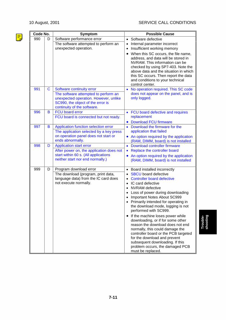
10 August, 2001 SERVICE CALL CONDITIONS
7-11
Trou
ble-
shoo
ting
Code No. Symptom Possible CauseSoftware performance error990 DThe software attempted to perform anunexpected operation.
• Software defective• Internal parameter incorrect• Insufficient working memory• When this SC occurs, the file name,
address, and data will be stored inNVRAM. This information can bechecked by using SP7-403. Note theabove data and the situation in whichthis SC occurs. Then report the dataand conditions to your technicalcontrol center.
Software continuity error991 CThe software attempted to perform anunexpected operation. However, unlikeSC990, the object of the error iscontinuity of the software.
• No operation required. This SC codedoes not appear on the panel, and isonly logged.
FCU board error996 BFCU board is connected but not ready.
• FCU board defective and requiresreplacement
• Download FCU firmwareApplication function selection error997 BThe application selected by a key presson operation panel does not start orends abnormally.
• Download the firmware for theapplication that failed
• An option required by the application(RAM, DIMM, board) is not installed
Application start error998 DAfter power on, the application does notstart within 60 s. (All applicationsneither start nor end normally.)
• Download controller firmware• Replace the controller board• An option required by the application
(RAM, DIMM, board) is not installed
Program download error999 DThe download (program, print data,language data) from the IC card doesnot execute normally.
• Board installed incorrectly• SBCU board defective• Controller board defective• IC card defective• NVRAM defective• Loss of power during downloading• Important Notes About SC999• Primarily intended for operating in
the download mode, logging is notperformed with SC999.
• If the machine loses power whiledownloading, or if for some otherreason the download does not endnormally, this could damage thecontroller board or the PCB targetedfor the download and preventsubsequent downloading. If thisproblem occurs, the damaged PCBmust be replaced.
Ricoh Technical Services
RTB 11, 11b SC990

SELF-DIAGNOSTIC MODE 10 August, 2001
7-12
7.2 SELF-DIAGNOSTIC MODE7.2.1 SELF-DIAGNOSTIC MODE AT POWER ON
As soon as the main machine is powered on, the controller waits for the initialsettings of the copy engine to take effect and then starts an independent self-diagnostic test program. The self-diagnostic test follows the path of the flow chartshown below and checks the CPU, memory, HDD, and so on. An SC code isdisplayed in the touch panel if the self-diagnostic program detects any malfunctionor abnormal condition.Self-Diagnostic Test Flow
Power On
ASIC Check
Initialization
Memory Check forSelf-Diagnostic Test
SSCG Check
HDD Check
Memory Check
OPC Check
IEEE1284I/F Check
CPU Check
Program ROM,DIMM CRC Check
NVRAM Check Illegal InterruptCheck
Font ROM Check
RTC Check
IC CardI/FCheck
Network Check
Engine I/F Check
System OS,Application Check
Self-DiagnosticMode Selection
B027T516.WMF

10 August, 2001 SELF-DIAGNOSTIC MODE
7-13
Trou
ble-
shoo
ting
7.2.2 DETAILED SELF-DIAGNOSTIC MODE
In addition to the self-diagnostic test initiated every time the main machine ispowered on, you can set the machine in a more detailed diagnostic mode manuallyin order to test other components or conditions that are not tested during self-diagnosis after power on. The following device is required in order to put themachine in the detailed self-diagnosis mode.
No. NameG02119350 Parallel Loopback Connector
Executing Detailed Self-DiagnosisFollow this procedure to execute detailed self-diagnosis.
1. Switch off the machine, and connect the parallel loopback device to theCentronics I/F port.
2. Hold down ", press and hold down #, and then while pressing both keys atthe same time, switch on the machine.You will see “Now Loading” on the touch-panel, and then you will see theresults of the test.

SELF-DIAGNOSTIC MODE 10 August, 2001
7-14
A report like the one below is printed every time a detailed self-diagnostic testis executed, whether errors were detected or not.
MODEL NAME XXXX
Serial No. : ACLD000034 Firmware P/# : ACP82XXXX [1/1]
Firmware Version : 2.49.01 Wed Nov 22 13:15:30 2000
[System Construction]
Kernel Version : NetBSD 1.3.3 (SHINYOKOHAMA_ROM) #0: Sat Nov 11 16:15:35 JST 2000
CPU System Bus Clock : 100.0 MHz CPU Pipeline Clock : 200.0 MHz
Board Type : 7 ASIC Version : 1397306160
RTC Existence : existence RAM Capacity : 100.663296 MB
HDD Existence : existence HDD Model :
[Total Counter ]
0001000
[Program No. @]
MAIN : ACP82XXXX ENGINE : Ver1.96
LCDC : V1.39 PI :
ADF : B3515620B SIB : B0045383
FIN : FIN_SDL :
BANK : A6825150 LCT :
MBX : FCU :
DPX :
[Error List @@@]
SCCODE (ERROR CODE ) SC CODE (ERROR CODE) SC CODE (ERROR CODE) SC CODE (ERROR CODE)
SC835 (110C) SC820 (0001) SC820 (0002) SC820 (0003)
SC820 (0004) SC820 (0005)
Self-Diagnosis Report
B027T515.WMF

10 August, 2001 PAPER FEED TROUBLESHOOTING
7-15
Trou
ble-
shoo
ting
7.3 PAPER FEED TROUBLESHOOTINGWhen a paper double feed or paper non feed problem occurs, fix the problem inaccordance with the following flow chart.
Tray1st Tray2nd Tray3rd Tray4th Tray
SP No.1-908-11-909-11-910-11-911-1
Change the value of thefollowing SP mode to a smallernumber.
Apply the bottom plate pressurefor normal paper size.
Tray1st Tray2nd Tray3rd Tray4th Tray
SP No.1-908-21-909-21-910-21-911-2
Change the value of thefollowing SP mode to a smallernumber.
Apply the bottom plate pressurefor small paper size.
Tray1st Tray2nd Tray3rd Tray4th Tray
SP No.1-908-41-909-41-910-41-911-4
Change the value of thefollowing SP mode to a largernumber.
Apply the bottom plate pressureat near-end condition for smallpaper size.
SP No.1-908-11-909-11-910-11-911-1
Tray1st Tray2nd Tray3rd Tray4th Tray
Change the value of thefollowing SP mode to a largernumber.
Reduce the bottom platepressure for normal paper size.
Tray1st Tray2nd Tray3rd Tray4th Tray
SP No.1-908-21-909-21-910-21-911-2
Change the value of thefollowing SP mode to a largernumber.
Reduce the bottom platepressure for small paper size.
Feed problemoccurs at papernear-end? *Note
Double FeedNon Feed
Small Paper Size?(A5/HLT)
Small Paper Size?(A5/HLT)
Paper Feed Problem
Yes
No
No No
Yes Yes
*Note:If the feed problemalways occurs at acertain point beforenear-end, change theremaining paperthreshold withSP 1-908-6, 1-909-6,1-910-6, and/or1-911-6
B027T500.WMF

SKEWED IMAGE 10 August, 2001
7-16
7.4 SKEWED IMAGEDo the following to fix a skewed image problem.
Print out the Trimming Pattern (SP2-902, no.10) from every paper tray.
Is the copy skewed? Make a copy using theADF
Do the following.
- Check the side fence position of the paper tray. - Clean or replace the paper feed roller. - Clean the registration roller. - Change the value of SP1-903 to a larger number.
Do the following.
- Check the side fence position of the original table. - Clean or replace the original feed belt, pick-up roller, and separation roller. - Clean the transport roller and exit roller. - Secure the ADF using the long hole, then adjust the ADF position.
Is the copy skewed? OK
No
Yes
No
Yes
B027T501.WMF
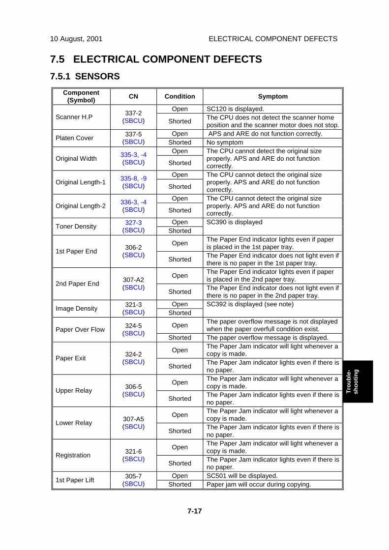
10 August, 2001 ELECTRICAL COMPONENT DEFECTS
7-17
Trou
ble-
shoo
ting
7.5 ELECTRICAL COMPONENT DEFECTS7.5.1 SENSORS
Component(Symbol) CN Condition Symptom
Open SC120 is displayed.Scanner H.P 337-2
(SBCU) Shorted The CPU does not detect the scanner homeposition and the scanner motor does not stop.
Open APS and ARE do not function correctly.Platen Cover 337-5(SBCU) Shorted No symptom
OpenOriginal Width 335-3, -4
(SBCU) Shorted
The CPU cannot detect the original sizeproperly. APS and ARE do not functioncorrectly.
OpenOriginal Length-1 335-8, -9
(SBCU) Shorted
The CPU cannot detect the original sizeproperly. APS and ARE do not functioncorrectly.
OpenOriginal Length-2 336-3, -4
(SBCU) Shorted
The CPU cannot detect the original sizeproperly. APS and ARE do not functioncorrectly.
OpenToner Density 327-3(SBCU) Shorted
SC390 is displayed
Open The Paper End indicator lights even if paperis placed in the 1st paper tray.1st Paper End 306-2
(SBCU) Shorted The Paper End indicator does not light even ifthere is no paper in the 1st paper tray.
Open The Paper End indicator lights even if paperis placed in the 2nd paper tray.2nd Paper End 307-A2
(SBCU) Shorted The Paper End indicator does not light even ifthere is no paper in the 2nd paper tray.
OpenImage Density 321-3(SBCU) Shorted
SC392 is displayed (see note)
Open The paper overflow message is not displayedwhen the paper overfull condition exist.Paper Over Flow 324-5
(SBCU) Shorted The paper overflow message is displayed.
Open The Paper Jam indicator will light whenever acopy is made.Paper Exit 324-2
(SBCU) Shorted The Paper Jam indicator lights even if there isno paper.
Open The Paper Jam indicator will light whenever acopy is made.Upper Relay 306-5
(SBCU) Shorted The Paper Jam indicator lights even if there isno paper.
Open The Paper Jam indicator will light whenever acopy is made.Lower Relay 307-A5
(SBCU) Shorted The Paper Jam indicator lights even if there isno paper.
Open The Paper Jam indicator will light whenever acopy is made.Registration 321-6
(SBCU) Shorted The Paper Jam indicator lights even if there isno paper.
Open SC501 will be displayed.1st Paper Lift 305-7(SBCU) Shorted Paper jam will occur during copying.
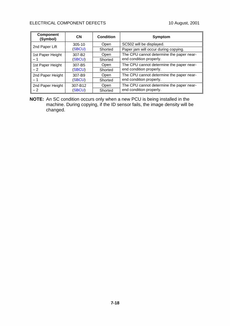
ELECTRICAL COMPONENT DEFECTS 10 August, 2001
7-18
Component(Symbol) CN Condition Symptom
Open SC502 will be displayed.2nd Paper Lift 305-10(SBCU) Shorted Paper jam will occur during copying.
Open1st Paper Height– 1
307-B2(SBCU) Shorted
The CPU cannot determine the paper near-end condition properly.
Open1st Paper Height– 2
307-B5(SBCU) Shorted
The CPU cannot determine the paper near-end condition properly.
Open2nd Paper Height– 1
307-B9(SBCU) Shorted
The CPU cannot determine the paper near-end condition properly.
Open2nd Paper Height– 2
307-B12(SBCU) Shorted
The CPU cannot determine the paper near-end condition properly.
NOTE: An SC condition occurs only when a new PCU is being installed in themachine. During copying, if the ID sensor fails, the image density will bechanged.

10 August, 2001 ELECTRICAL COMPONENT DEFECTS
7-19
Trou
ble-
shoo
ting
7.5.2 SWITCHESComponent
(Symbol) CN Condition Symptom
Open The machine does not turn on.Main 281-1,2(PSU) Shorted The machine does not turn off.
Open The Cover Open indicator is not lit even if theright upper cover is opened.Right Upper
Cover324-8
(SBCU) Shorted The Cover Open indicator is lit even if theright upper cover is closed.
Open The Cover Open indicator is not lit even if theright cover is opened.Right Cover 308-9
(SBCU) Shorted The Cover Open indicator is lit even if theright cover is closed.
Open The Cover Open indicator is not lit even if theright lower cover is opened.Right Lower
Cover307-A8(SBCU) Shorted The Cover Open indicator is lit even if the
right lower cover is closed.OpenUpper Paper
Size308-1,2,4,5
(SBCU) Shorted
The CPU cannot detect the proper papersize, and misfeeds may occur when a copy ismade.
OpenLower PaperSize
308-6,7,9,10(SBCU) Shorted
The CPU cannot detect the proper papersize, and misfeeds may occur when a copy ismade.
Open The TD sensor initial setting procedure is notperformed when a new PCU is installed.New PCU Detect 327-7
(SBCU) Shorted The TD sensor initial setting procedure isperformed whenever the front cover is closed.
Open The Cover Open indicator is not lit even if thefront cover is opened.Front Cover
Safety311-2, 4(SBCU) Shorted The Cover Open indicator is lit even if the
front cover is closed.
Open The LCD does not off even if the operationswitch is turned off.Operation 105-1
(IPU Shorted The LCD does not on even if the operationswitch is turned on.
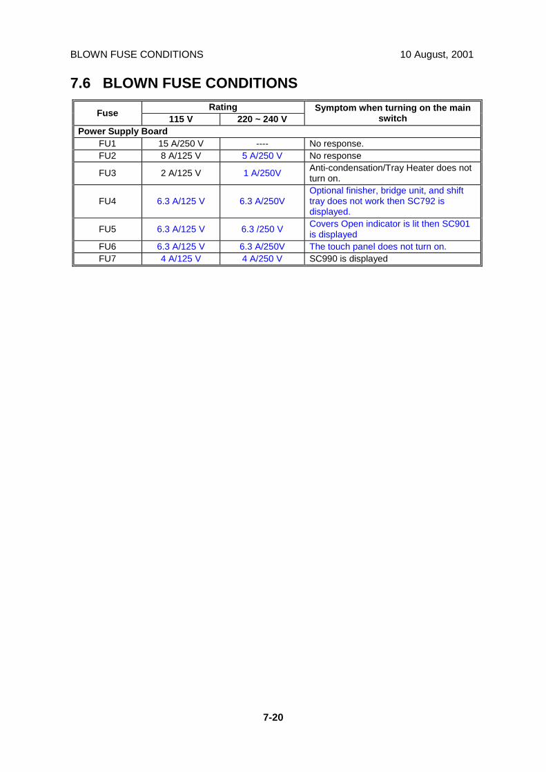
BLOWN FUSE CONDITIONS 10 August, 2001
7-20
7.6 BLOWN FUSE CONDITIONSRatingFuse 115 V 220 ~ 240 V
Symptom when turning on the mainswitch
Power Supply BoardFU1 15 A/250 V ---- No response.FU2 8 A/125 V 5 A/250 V No response
FU3 2 A/125 V 1 A/250V Anti-condensation/Tray Heater does notturn on.
FU4 6.3 A/125 V 6.3 A/250VOptional finisher, bridge unit, and shifttray does not work then SC792 isdisplayed.
FU5 6.3 A/125 V 6.3 /250 V Covers Open indicator is lit then SC901is displayed
FU6 6.3 A/125 V 6.3 A/250V The touch panel does not turn on.FU7 4 A/125 V 4 A/250 V SC990 is displayed

9 November, 2001 RSS SET UP
APPENDIX-1
APPENDIX 1 (FOR MODEL R-C2)1. RSS (REMOTE SERVICE SYSTEM)1.1 RSS SET UP
!CAUTIONUnplug the machine power cord before starting the following procedure.
1. Remove the connector cover [A] (1 clip) and disconnect the cable.2. Remove the rear cover [B] (4 screws).3. Remove the duplex connector cover [C] (1 screw) and the lower rear cover [D]
(2 screws).4. Install the RSS board [E] (2 screws).5. Install the harness [F] between the RSS board and the SBCU board (CN512).When connecting only one machine to the line adapter, skip step 6.6. Set the jumper switch [G] on the RSS board as shown (default setting: 1-2).7. Remove the cover [H] from the lower rear cover.
B027R515.WMFB027R705.WMF
B027I900.WMFB027I305.WMF
[A]
[B]
[E]
[F]
[H]
[C]
[D]
[G]

RSS SET UP 9 November, 2001
APPENDIX-2
Machine No. 1 2 3 4 5Jumper Set 2-3 2-3 2-3 2-3 1-2PI device code 0 1 2 3 4
8. Reassemble the machine.9. Connect the modular cord [A] to the line adapter as shown.10. Install the line adapter (refer to chapter 2-1 L-ADP Installation Procedure in the
CSS Service Manual).11. Turn on the machine.When connecting only one machine to the line adapter, skip step 12.12. Enter the Copier SP mode and set the PI device code with SP5-821 (default 0).
NOTE: After changing the value, turn the main power switch off and on toenable the PI device code.
Line Adapter
B027I902.WMF
B027I901.WMF
[A]

9 November, 2001 SP MODE SETTINGS
APPENDIX-3
1.2 SP MODE SETTINGSAfter installing the machine and line adapter, change the value of SP5-816 (CSSFunction) to 1.Check the values of the following SP modes. Ensure they are set correctly.NOTE: SP5-507 is only for the Japanese version. Do not change.• SP5-501-1 (PM Alarm Interval): 120k• SP5-504 (Jam Alarm Setting): 3• SP5-505 (Error Alarm Setting): 50• SP5-508-1 (CC Call – Remain of Jam): 1 (On)• SP5-508-2 (CC Call – Continuous Jam Occurrence): 1 (On)• SP5-508-3 (CC Call - Cover Open): 1 (On)• SP5-508-4 (New CC Call Mode): 1 (New Mode)
1.3 CHECKING ITEMS USING RSS1.3.1 READ ONLY ITEMS
ItemPaper endToner endStaple endToner near endDoor openPaper jam informationMachine conditionPaper size informationSystem configurationVsg, Vsp, Vsdp, Vt dataFax information (Total No. of Tx, Total No. of Rx, Quick dial, Speed dial, etc)Printer information (Total No. of print by Emulation, Bit switches, etc)SP7-001~-003, -101, -204~-206, -301~-305, -320~-328, -401, -403, -502~-507, -801, -803
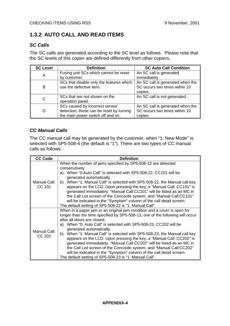
CHECKING ITEMS USING RSS 9 November, 2001
APPENDIX-4
1.3.2 AUTO CALL AND READ ITEMS
SC CallsThe SC calls are generated according to the SC level as follows. Please note thatthe SC levels of this copier are defined differently from other copiers.
SC Level Definition SC Auto Call ConditionA Fusing unit SCs which cannot be reset
by customer.An SC call is generatedimmediately
BSCs that disable only the features whichuse the defective item.
An SC call is generated when theSC occurs two times within 10copies.
C SCs that are not shown on theoperation panel.
An SC call is not generated.
DSCs caused by incorrect sensordetection; these can be reset by turningthe main power switch off and on.
An SC call is generated when theSC occurs two times within 10copies.
CC Manual CallsThe CC manual call may be generated by the customer, when “1: New Mode” isselected with SP5-508-4 (the default is “1”). There are two types of CC manualcalls as follows.
CC Code Definition
Manual Call:CC 101
When the number of jams specified by SP5-508-12 are detectedconsecutively:a). When “0:Auto Call” is selected with SP5-508-22, CC101 will be
generated automatically.b). When “1: Manual Call” is selected with SP5-508-22, the Manual call key
appears on the LCD. Upon pressing the key, a “Manual Call: CC101” isgenerated immediately. “Manual Call:CC101” will be listed as an MC inthe Call List screen of the Concorde system, and “Manual Call:CC101”will be indicated in the “Symptom” column of the call detail screen.
The default setting of SP5-508-22 is “1: Manual Call”.
Manual Call:CC 202
When in a paper jam or an original jam condition and a cover is open forlonger than the time specified by SP5-508-13, one of the following will occurafter all doors are closed.a). When “0: Auto Call” is selected with SP5-508-23, CC202 will be
generated automatically.b). When “1: Manual Call” is selected with SP5-508-23, the Manual call key
appears on the LCD. Upon pressing the key, a “Manual Call: CC202” isgenerated immediately. “Manual Call:CC202” will be listed as an MC inthe Call List screen of the Concorde system, and “Manual Call:CC202”will be indicated in the “Symptom” column of the call detail screen.
The default setting of SP5-508-23 is “1: Manual Call”.

9 November, 2001 CHECKING ITEMS USING RSS
APPENDIX-5
CC Auto CallThe CC auto call will be automatically generated when “0: Previous Mode” isselected with SP5-508-4 (default is “1”). There are three types of CC auto calls asfollows.
CC Code DefinitionCC 101 When a paper jam is detected five times consecutively, CC101 is
automatically generated.
CC 201 When a paper jam condition is not reset for 15 minutes, CC201 isautomatically generated.
CC 202 When a cover is left open for 15 minutes, CC202 is automaticallygenerated.
Alarm CallsThere are four types of Alarm Calls as follows:
Type DefinitionPM When the PM counter reaches 120,000, a PM Alarm Call is automatically
reported to the Concorde system.
Original Count An alarm call is generated after the specified total number of originals goesthrough the ARDF.
SCWhen the SC alarm counter reaches 5, an SC Alarm Call is automaticallygenerated. The SC alarm counter counts the number of SCs and itdecreases when an SC does not occur for a specified number of copies.
Jam
When Jam alarm counter reaches 10, a Jam Alarm Call is automaticallygenerated. The Jam Alarm counter counts the number of paper jams and itdecreases when a paper jam does not occur for a specified number ofcopies.
1.3.3 READ AND WRITE ITEMS
All data for SP modes and UP modes, except for a few modes.
1.3.4 EXECUTE ITEMSItem Item
Memory all clear Counter reset (all except total counter)SC reset Original counter resetPM counter reset Copy counter resetSC/Jam counter reset Reset counters by each paper tray
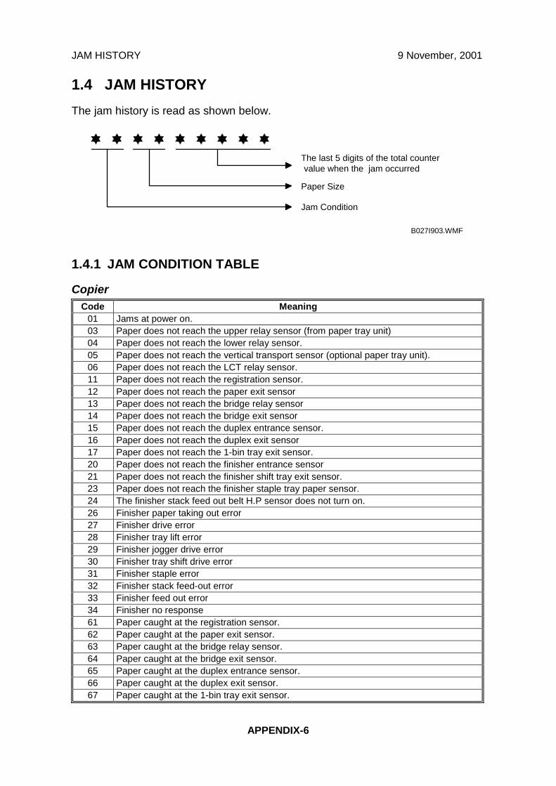
JAM HISTORY 9 November, 2001
APPENDIX-6
1.4 JAM HISTORYThe jam history is read as shown below.
1.4.1 JAM CONDITION TABLE
CopierCode Meaning
01 Jams at power on.03 Paper does not reach the upper relay sensor (from paper tray unit)04 Paper does not reach the lower relay sensor.05 Paper does not reach the vertical transport sensor (optional paper tray unit).06 Paper does not reach the LCT relay sensor.11 Paper does not reach the registration sensor.12 Paper does not reach the paper exit sensor13 Paper does not reach the bridge relay sensor14 Paper does not reach the bridge exit sensor15 Paper does not reach the duplex entrance sensor.16 Paper does not reach the duplex exit sensor17 Paper does not reach the 1-bin tray exit sensor.20 Paper does not reach the finisher entrance sensor21 Paper does not reach the finisher shift tray exit sensor.23 Paper does not reach the finisher staple tray paper sensor.24 The finisher stack feed out belt H.P sensor does not turn on.26 Finisher paper taking out error27 Finisher drive error28 Finisher tray lift error29 Finisher jogger drive error30 Finisher tray shift drive error31 Finisher staple error32 Finisher stack feed-out error33 Finisher feed out error34 Finisher no response61 Paper caught at the registration sensor.62 Paper caught at the paper exit sensor.63 Paper caught at the bridge relay sensor.64 Paper caught at the bridge exit sensor.65 Paper caught at the duplex entrance sensor.66 Paper caught at the duplex exit sensor.67 Paper caught at the 1-bin tray exit sensor.
The last 5 digits of the total countervalue when the jam occurred
Paper Size
Jam Condition
B027I903.WMF

9 November, 2001 OTHERS
APPENDIX-7
Document FeederCode Meaning
01 Jam at power on.05 Original does not reach the registration sensor.06 Original does not reach the original exit sensor.07 Original does not reach the original reverse sensor.55 Original caught at the registration sensor.56 Original caught at the original exit sensor.57 Original caught at the original reverse sensor.
1.4.2 PAPER SIZECode Paper Size Code Paper Size
05 A4 sideways 86 A5 lengthwise06 A5 sideways 87 A6 lengthwise07 A6 sideways 8D B40E B5 sideways 8E B5 lengthwise0F B6 sideways 8F B6 lengthwise11 Prepaid reply post card sideways 91 Prepaid reply post card lengthwise12 Post card sideways 92 Post card lengthwise24 8.5" x 14" sideways A0 11" x 17"26 8.5" x 11" sideways A4 8.5" x 14" lengthwise2C 8.5" x 5.5" sideways A6 8.5" x 11" lengthwise84 A3 AC 8.5" x 5.5" lengthwise85 A4 lengthwise
1.5 OTHERS1.5.1 SC630 [RDS COMMUNICATION ERROR]
Frequent occurrence of SC630 indicates a problem in the customer’scommunication line or line adapter. To maintain the communications environmentin good working order, it is necessary to make planned inspections periodically.
1.5.2 PM PROCEDURE OR OTHER MAINTENANCEBefore beginning PM or other maintenance procedures, SP5-816-2 should be setto "0". This will disable the RSS function. When maintenance is completed, SP5-816-2 should be set to "1". This will re-enable the RSS function.NOTE: The RSS function will remain disabled for four hours. Therefore, if
maintenance for longer than four hours is required, SP5-816-2 should beset to "0" again to disable RSS.


