SARGENT E -M P • 1 e SARGENT Electro-Mechanical Access Control General Information...
30
SARGENT ELECTRO-MECHANICAL PRODUCTS © SARGENT Manufacturing Company All rights reserved e
-
Upload
phungthuan -
Category
Documents
-
view
219 -
download
5
Transcript of SARGENT E -M P • 1 e SARGENT Electro-Mechanical Access Control General Information...
SARGENT
ELECTRO-MECHANICAL
PRODUCTS
© SARGENT Manufacturing Company All rights reserved
e
7/20
/07
© S
AR
GEN
T M
anu
fact
uri
ng
Co
mp
any
All
rig
hts
res
erve
d
1-800-727-5477 • www.sargentlock.com
e SARGENT Electro-Mechanical Access ControlProducts
Table of Contents
Table of Content & General Information . . . . . . . . . . . . . . . . . . .Inside Front CoverElectroLynx® Connector & Color Chart . . . . . . . . . . . . . . . . . . . . . . . . . . . . . . . . . . .1Profile Series Access Control Products• v.N1 Networked Access Control Products . . . . . . . . . . . . . . . . . . . . . . . . . . . . .2-3• v.G1.5 Stand Alone Access Control Products . . . . . . . . . . . . . . . . . . . . . . . . . .4-5• SofLink Plus™ Access Control Management Software . . . . . . . . . . . . . . . . . . . . .6• LK, LU, PK & PA Stand Alone Access Control Products . . . . . . . . . . . . . . . . . . . .7• Biometric Security - Biofob for Profile Series v.N1 & v.G1.5 . . . . . . . . . . . . . . . .8• Access Credentials and Accessories for Profile Series v.N1 & v.G1.5 . . . . . . . . .9• Profile Series v.G1.5 - 4293 Wall Prox/Keypad . . . . . . . . . . . . . . . . . . . . . . . . . .10
Power Supplies and Accessories . . . . . . . . . . . . . . . . . . . . . . . . . . . . . . . . . . . . . . . .11Keypad Operated Products . . . . . . . . . . . . . . . . . . . . . . . . . . . . . . . . . . . . . . . . . . .12Solenoid Controlled Products & Monitoring Options . . . . . . . . . . . . . . . . . . . . . .13Lever Trim Designs . . . . . . . . . . . . . . . . . . . . . . . . . . . . . . . . . . . . . . . . . . . . . . . .14-15Electro-Mechanical Exit Devices• SARGuide Electro Luminescent Exit Device (TL-)
and Alarmed Exit Devices (AL-) . . . . . . . . . . . . . . . . . . . . . . . . . . . . . . . . . . . . .16• Latchbolt Monitoring (53-), Rail Monitoring (55-)
& Electric Latch Retraction (56-) . . . . . . . . . . . . . . . . . . . . . . . . . . . . . . . . . . . . .17• Delayed Egress Device (57- and Electromagnets . . . . . . . . . . . . . . . . . . . . . . . .18• Electric Dogging (58-) and Electroguard Delayed Egress (59-) . . . . . . . . . . . . .19
5100/5800 Alarmed Exit, 540/550 SERIES ALARMS & 268 Concealed Closer with Monitoring . . . . . . . . . . . . . . . . . . . . . . . . . . . . . . . .202408 & 2900 Fire Guard Closer-Holder . . . . . . . . . . . . . . . . . . . . . . . . . . . . . . . . . .21351 EHT/EHTD Closer-Holder and Electromagnet Door Holders . . . . . . . . . . . . . .22Low Energy Door Operators/ The MPower Series . . . . . . . . . . . . . . . . . . . . . . . . .23Wall Switches and Wireless Options . . . . . . . . . . . . . . . . . . . . . . . . . . . . . . . . . . . .24Monitoring Accessories & Door Status Switches . . . . . . . . . . . . . . . . . . . . . . . . . .25Key switches and Card Readers . . . . . . . . . . . . . . . . . . . . . . . . . . . . . . . . . . . . . . . .26Keypads, Push Buttons and Switch Locks . . . . . . . . . . . . . . . . . . . . . . . . . . . . . . . .27Electric Hinges and Door Loops . . . . . . . . . . . . . . . . . . . . . . . . . . . . . . . .Back Cover
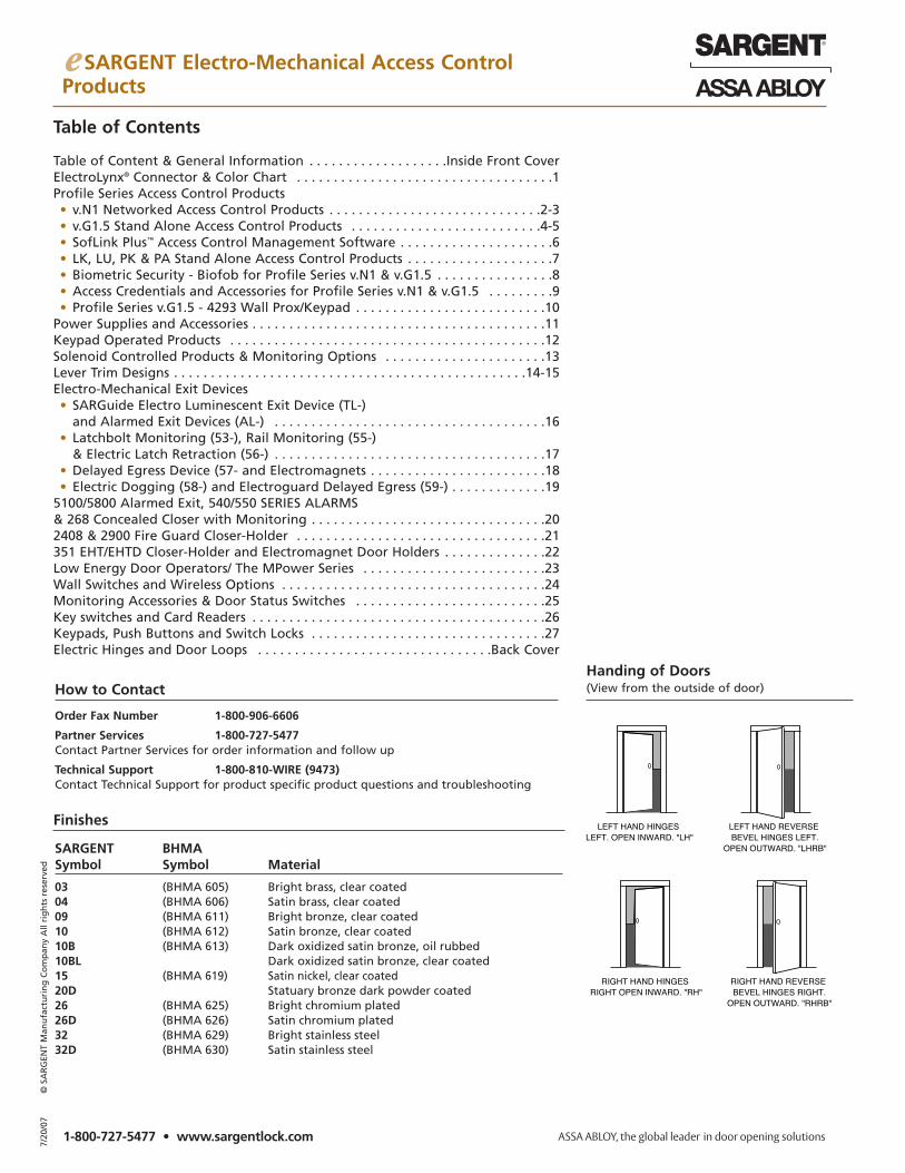
How to ContactHanding of Doors(View from the outside of door)
SARGENT BHMASymbol Symbol Material
03 (BHMA 605) Bright brass, clear coated04 (BHMA 606) Satin brass, clear coated09 (BHMA 611) Bright bronze, clear coated 10 (BHMA 612) Satin bronze, clear coated10B (BHMA 613) Dark oxidized satin bronze, oil rubbed 10BL Dark oxidized satin bronze, clear coated15 (BHMA 619) Satin nickel, clear coated20D Statuary bronze dark powder coated26 (BHMA 625) Bright chromium plated 26D (BHMA 626) Satin chromium plated32 (BHMA 629) Bright stainless steel 32D (BHMA 630) Satin stainless steel
Order Fax Number 1-800-906-6606
Partner Services 1-800-727-5477Contact Partner Services for order information and follow up
Technical Support 1-800-810-WIRE (9473)Contact Technical Support for product specific product questions and troubleshooting
Finishes
11-800-727-5477 • www.sargentlock.com
e SARGENT Electro-Mechanical Access ControlGeneral Information
ElectroLynx®. The easy answer to your hardwiring issues.
ASSA ABLOY Door Security Solutions has revolutionized the installation of electromechanical door hardware with ElectroLynx, a wiringsystem of universal plug-in connectors and standardized color-coded wiring that makes installation a snap. Now, sophisticated accesscontrol products can be connected quickly and easily. Rapidly becoming the industry standard, this fool-proof system is as easy asplugging a telephone into a jack.
ElectroLynx components – including the frame, hinge or pivot, door and locking hardware – are pre-wired with plug-in connectors thatsnap together to create a fully-wired electrical opening. The plugs and wiring are concealed to preserve the aesthetics of the openingand facilitate any future hardware changes.
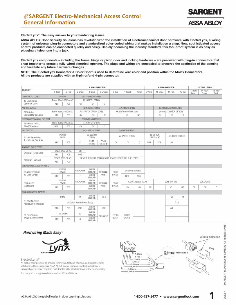
NOTE: The ElectroLynx Connector & Color Chart is used to determine wire color and position within the Molex Connectors. All the products are supplied with an 8-pin or/and 4-pin connector.
17 5
6 4
3
28
1, Black
2, Red
4, Green3, White
5, Orange
7, Brown8, Yellow
6, Blue
Plug
Locking mechanism
Receptacle
ElectroLynx®
As part of their promise to provide innovative, fast and effective, and higher security solutions to their customers, ASSA ABLOY Group companies offer ElectroLynx, a universal quick-connect system that simplifies the electrification of the door opening.
ElectroLynx® is a registered trademark of ASSA ABLOY, Inc.
7/20
/07
© S
AR
GEN
T M
anu
fact
uri
ng
Co
mp
any
All
rig
hts
res
erve
d
27/20
/07
© S
AR
GEN
T M
anu
fact
uri
ng
Co
mp
any
All
rig
hts
res
erve
d
1-800-727-5477 • www.sargentlock.com
e SARGENT Electro-Mechanical Access ControlProfile Series v.N1Wiegand Access Control Products
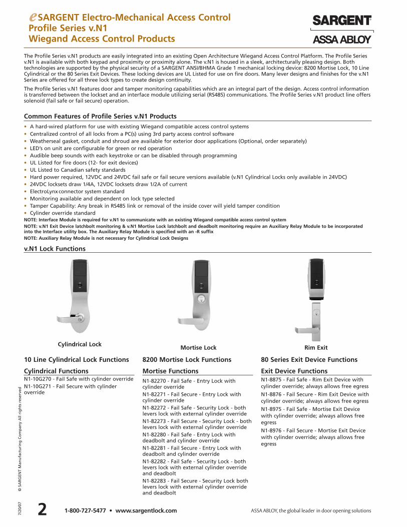
The Profile Series v.N1 products are easily integrated into an existing Open Architecture Wiegand Access Control Platform. The Profile Seriesv.N1 is available with both keypad and proximity or proximity alone. The v.N1 is housed in a sleek, architecturally pleasing design. Bothtechnologies are supported by the physical security of a SARGENT ANSI/BHMA Grade 1 mechanical locking device: 8200 Mortise Lock, 10 LineCylindrical or the 80 Series Exit Devices. These locking devices are UL Listed for use on fire doors. Many lever designs and finishes for the v.N1Series are offered for all three lock types to create design continuity.
The Profile Series v.N1 features door and tamper monitoring capabilities which are an integral part of the design. Access control informationis transferred between the lockset and an interface module utilizing serial (RS485) communications. The Profile Series v.N1 product line offerssolenoid (fail safe or fail secure) operation.
Common Features of Profile Series v.N1 Products• A hard-wired platform for use with existing Wiegand compatible access control systems• Centralized control of all locks from a PC(s) using 3rd party access control software• Weatherseal gasket, conduit and shroud are available for exterior door applications (Optional, order separately)• LED’s on unit are configurable for green or red operation• Audible beep sounds with each keystroke or can be disabled through programming• UL Listed for fire doors (12- for exit devices)• UL Listed to Canadian safety standards• Hard power required, 12VDC and 24VDC fail safe or fail secure versions available (v.N1 Cylindrical Locks only available in 24VDC)• 24VDC locksets draw 1/4A, 12VDC locksets draw 1/2A of current• ElectroLynx connector system standard• Monitoring available and dependent on lock type selected• Tamper Capability: Any break in RS485 link or removal of the inside cover will yield tamper condition• Cylinder override standardNOTE: Interface Module is required for v.N1 to communicate with an existing Wiegand compatible access control systemNOTE: v.N1 Exit Device latchbolt monitoring & v.N1 Mortise Lock latchbolt and deadbolt monitoring require an Auxiliary Relay Module to be incorporatedinto the Interface utility box. The Auxiliary Relay Module is specified with an -R suffix NOTE: Auxiliary Relay Module is not necessary for Cylindrical Lock Designs
Cylindrical Lock Mortise Lock Rim Exit
10 Line Cylindrical Lock Functions 8200 Mortise Lock Functions 80 Series Exit Device Functions
Cylindrical FunctionsN1-10G270 - Fail Safe with cylinder overrideN1-10G271 - Fail Secure with cylinder override
Mortise FunctionsN1-82270 - Fail Safe - Entry Lock with cylinder overrideN1-82271 - Fail Secure - Entry Lock withcylinder overrideN1-82272 - Fail Safe - Security Lock - bothlevers lock with external cylinder overrideN1-82273 - Fail Secure - Security Lock - bothlevers lock with external cylinder overrideN1-82280 - Fail Safe - Entry Lock with deadbolt and cylinder overrideN1-82281 - Fail Secure - Entry Lock withdeadbolt and cylinder overrideN1-82282 - Fail Safe - Security Lock - bothlevers lock with external cylinder overrideand deadboltN1-82283 - Fail Secure - Security Lock bothlevers lock with external cylinder overrideand deadbolt
Exit Device FunctionsN1-8875 - Fail Safe - Rim Exit Device withcylinder override; always allows free egress
N1-8876 - Fail Secure - Rim Exit Device withcylinder override; always allows free egress
N1-8975 - Fail Safe - Mortise Exit Devicewith cylinder override; always allows freeegress
N1-8976 - Fail Secure - Mortise Exit Devicewith cylinder override; always allows freeegress
v.N1 Lock Functions
e SARGENT Electro-Mechanical Access ControlProfile Series v.N1Wiegand Access Control Products
3 7/20
/07
© S
AR
GEN
T M
anu
fact
uri
ng
Co
mp
any
All
rig
hts
res
erve
d
1-800-727-5477 • www.sargentlock.com
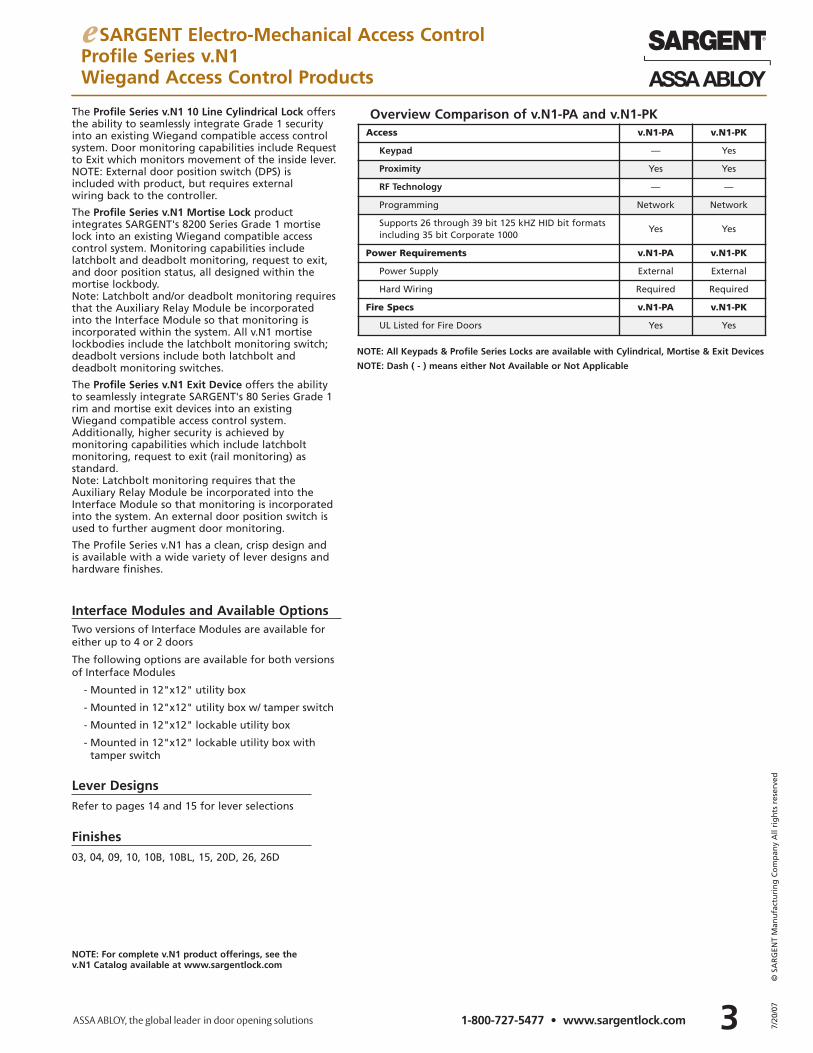
The Profile Series v.N1 10 Line Cylindrical Lock offersthe ability to seamlessly integrate Grade 1 securityinto an existing Wiegand compatible access controlsystem. Door monitoring capabilities include Requestto Exit which monitors movement of the inside lever. NOTE: External door position switch (DPS) is included with product, but requires external wiring back to the controller.
The Profile Series v.N1 Mortise Lock product integrates SARGENT's 8200 Series Grade 1 mortiselock into an existing Wiegand compatible accesscontrol system. Monitoring capabilities include latchbolt and deadbolt monitoring, request to exit,and door position status, all designed within themortise lockbody. Note: Latchbolt and/or deadbolt monitoring requiresthat the Auxiliary Relay Module be incorporatedinto the Interface Module so that monitoring isincorporated within the system. All v.N1 mortiselockbodies include the latchbolt monitoring switch;deadbolt versions include both latchbolt and deadbolt monitoring switches.
The Profile Series v.N1 Exit Device offers the abilityto seamlessly integrate SARGENT's 80 Series Grade 1rim and mortise exit devices into an existingWiegand compatible access control system.Additionally, higher security is achieved by monitoring capabilities which include latchbolt monitoring, request to exit (rail monitoring) as standard. Note: Latchbolt monitoring requires that theAuxiliary Relay Module be incorporated into theInterface Module so that monitoring is incorporatedinto the system. An external door position switch isused to further augment door monitoring.
The Profile Series v.N1 has a clean, crisp design andis available with a wide variety of lever designs andhardware finishes.
Finishes03, 04, 09, 10, 10B, 10BL, 15, 20D, 26, 26D
Lever DesignsRefer to pages 14 and 15 for lever selections
Interface Modules and Available Options
Overview Comparison of v.N1-PA and v.N1-PKAccess v.N1-PA v.N1-PK
Keypad — Yes
Proximity Yes Yes
RF Technology — —
Programming Network Network
Supports 26 through 39 bit 125 kHZ HID bit formatsincluding 35 bit Corporate 1000
Yes Yes
Power Requirements v.N1-PA v.N1-PK
Power Supply External External
Hard Wiring Required Required
Fire Specs v.N1-PA v.N1-PK
UL Listed for Fire Doors Yes Yes
NOTE: All Keypads & Profile Series Locks are available with Cylindrical, Mortise & Exit Devices
NOTE: Dash ( - ) means either Not Available or Not Applicable
NOTE: For complete v.N1 product offerings, see the v.N1 Catalog available at www.sargentlock.com
Two versions of Interface Modules are available foreither up to 4 or 2 doors
The following options are available for both versionsof Interface Modules
- Mounted in 12"x12" utility box
- Mounted in 12"x12" utility box w/ tamper switch
- Mounted in 12"x12" lockable utility box
- Mounted in 12"x12" lockable utility box withtamper switch
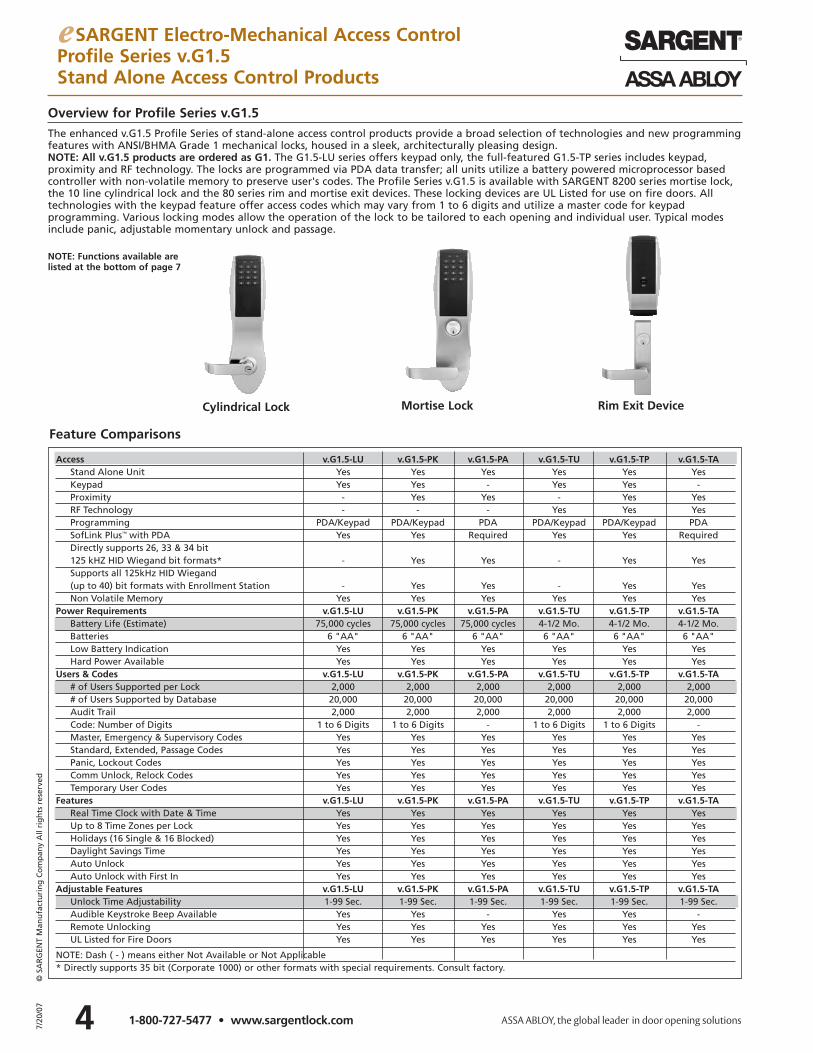
Overview for Profile Series v.G1.5The enhanced v.G1.5 Profile Series of stand-alone access control products provide a broad selection of technologies and new programmingfeatures with ANSI/BHMA Grade 1 mechanical locks, housed in a sleek, architecturally pleasing design. NOTE: All v.G1.5 products are ordered as G1. The G1.5-LU series offers keypad only, the full-featured G1.5-TP series includes keypad, proximity and RF technology. The locks are programmed via PDA data transfer; all units utilize a battery powered microprocessor basedcontroller with non-volatile memory to preserve user's codes. The Profile Series v.G1.5 is available with SARGENT 8200 series mortise lock,the 10 line cylindrical lock and the 80 series rim and mortise exit devices. These locking devices are UL Listed for use on fire doors. All technologies with the keypad feature offer access codes which may vary from 1 to 6 digits and utilize a master code for keypad programming. Various locking modes allow the operation of the lock to be tailored to each opening and individual user. Typical modesinclude panic, adjustable momentary unlock and passage.
Cylindrical Lock Mortise Lock Rim Exit Device
e SARGENT Electro-Mechanical Access ControlProfile Series v.G1.5Stand Alone Access Control Products
47/20
/07
© S
AR
GEN
T M
anu
fact
uri
ng
Co
mp
any
All
rig
hts
res
erve
d
1-800-727-5477 • www.sargentlock.com
Feature Comparisons
NOTE: Functions available arelisted at the bottom of page 7
Access v.G1.5-LU v.G1.5-PK v.G1.5-PA v.G1.5-TU v.G1.5-TP v.G1.5-TAStand Alone Unit Yes Yes Yes Yes Yes YesKeypad Yes Yes - Yes Yes -Proximity - Yes Yes - Yes YesRF Technology - - - Yes Yes YesProgramming PDA/Keypad PDA/Keypad PDA PDA/Keypad PDA/Keypad PDASofLink Plus™ with PDA Yes Yes Required Yes Yes RequiredDirectly supports 26, 33 & 34 bit 125 kHZ HID Wiegand bit formats* - Yes Yes - Yes YesSupports all 125kHz HID Wiegand (up to 40) bit formats with Enrollment Station - Yes Yes - Yes YesNon Volatile Memory Yes Yes Yes Yes Yes Yes
Power Requirements v.G1.5-LU v.G1.5-PK v.G1.5-PA v.G1.5-TU v.G1.5-TP v.G1.5-TABattery Life (Estimate) 75,000 cycles 75,000 cycles 75,000 cycles 4-1/2 Mo. 4-1/2 Mo. 4-1/2 Mo.Batteries 6 "AA" 6 "AA" 6 "AA" 6 "AA" 6 "AA" 6 "AA"Low Battery Indication Yes Yes Yes Yes Yes YesHard Power Available Yes Yes Yes Yes Yes Yes
Users & Codes v.G1.5-LU v.G1.5-PK v.G1.5-PA v.G1.5-TU v.G1.5-TP v.G1.5-TA# of Users Supported per Lock 2,000 2,000 2,000 2,000 2,000 2,000# of Users Supported by Database 20,000 20,000 20,000 20,000 20,000 20,000Audit Trail 2,000 2,000 2,000 2,000 2,000 2,000Code: Number of Digits 1 to 6 Digits 1 to 6 Digits - 1 to 6 Digits 1 to 6 Digits -Master, Emergency & Supervisory Codes Yes Yes Yes Yes Yes YesStandard, Extended, Passage Codes Yes Yes Yes Yes Yes YesPanic, Lockout Codes Yes Yes Yes Yes Yes YesComm Unlock, Relock Codes Yes Yes Yes Yes Yes YesTemporary User Codes Yes Yes Yes Yes Yes Yes
Features v.G1.5-LU v.G1.5-PK v.G1.5-PA v.G1.5-TU v.G1.5-TP v.G1.5-TAReal Time Clock with Date & Time Yes Yes Yes Yes Yes YesUp to 8 Time Zones per Lock Yes Yes Yes Yes Yes YesHolidays (16 Single & 16 Blocked) Yes Yes Yes Yes Yes YesDaylight Savings Time Yes Yes Yes Yes Yes YesAuto Unlock Yes Yes Yes Yes Yes YesAuto Unlock with First In Yes Yes Yes Yes Yes Yes
Adjustable Features v.G1.5-LU v.G1.5-PK v.G1.5-PA v.G1.5-TU v.G1.5-TP v.G1.5-TAUnlock Time Adjustability 1-99 Sec. 1-99 Sec. 1-99 Sec. 1-99 Sec. 1-99 Sec. 1-99 Sec.Audible Keystroke Beep Available Yes Yes - Yes Yes -Remote Unlocking Yes Yes Yes Yes Yes YesUL Listed for Fire Doors Yes Yes Yes Yes Yes Yes
NOTE: Dash ( - ) means either Not Available or Not Applicable* Directly supports 35 bit (Corporate 1000) or other formats with special requirements. Consult factory.
RF Technology
e SARGENT Electro-Mechanical Access ControlProfile Series v.G1.5Stand Alone Access Control Products
5 7/20
/07
© S
AR
GEN
T M
anu
fact
uri
ng
Co
mp
any
All
rig
hts
res
erve
d
1-800-727-5477 • www.sargentlock.com
Standard Features of the v.G1.5• Audit Trail provides information such as
access granted in, access denied, entry into programming mode, date, time, user and door information
• Low battery indication – four chirps aftercode entry. Master and emergency codewill operate lock after the low batteryindication period has passed and usercodes no longer operate the lock
• Moisture resistant coating on electronics• Entry of three wrong user codes in
succession disables all codes for ten seconds
• UL Listed to Canadian safety standards• Forced and propped door option• For use on exterior doors with
weatherseal gasket, conduit and shroud(Optional, order separately
• One master code – Forced master codefrom factory default assigns emergency,supervisory and user codes and allowsentry when deadbolt is thrown (mortiselocks)– Multiple supervisory codes – Allows
temporary lockout of selected users,change unlock time duration,requestinfrared interrogation output and adduser codes
– One emergency code – Allows entrywhen dead bolt is thrown (mortiselocks). Unlocks after the low batteryindication period has passed and usercodes no longer operate lock
– Temporary codes by number of uses (1-500), start-and-stop dates or totaldays after first use (24 hour specific)
– Maintained (passage) code – Unlocks forextended periods of time
• Remote power and request to enter available – Requires wire harness (52-3010) and hard wiring
Keypad Features• LEDs on unit indicate status – Green
indicates unlocked; yellow indicates programming mode
Proximity Features• Supports all HID 125 KHz Wiegand formats
(up to 40 bit) by Keypad Presentation orwhen using proximity enrollment stationES-G1 with SofLink Plus 5 software
• Supports 26, 34 & SARGENT 1000 (33 bit)HID formats with SofLink PlusTM version 4.0or higher software programming
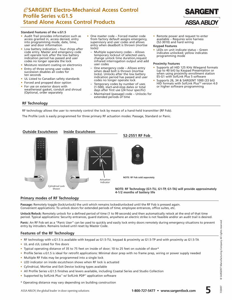
52-2551 RF FobInside Escutcheon
RF technology allows the user to remotely control the lock by means of a hand-held transmitter (RF Fob).
The Profile Lock is easily programmed for three primary RF actuation modes: Passage, Standard or Panic.
Passage: Remotely toggle (lock/unlock) the unit which remains locked/unlocked until the RF Fob is pressed again. Convenient applications: To unlock doors for extended periods of time; employee entrances, office suites, etc.
Unlock/Relock: Remotely unlock for a defined period of time (1 to 99 seconds) and then automatically relock at the end of that timeperiod. Typical applications: Security entrances, guard stations, anywhere an electric strike is not feasible and/or an audit trail is desired.
Panic: An RF Fob set as a “Panic User” can be used to quickly and easily lock entry doors remotely during emergency situations to prevententry by intruders. Remains locked until reset by Master Code.
Outside Escutcheon
Features of the RF Technology
Primary modes of RF Technology
• RF technology with v.G1.5 is available with keypad as G1.5-TU, keypad & proximity as G1.5-TP and with proximity as G1.5-TA
• UL and cUL Listed for fire doors
• Typical operating distance of 35 to 75 feet on inside of door; 10 to 25 feet on outside of door*
• Profile Series v.G1.5 is ideal for retrofit applications: Minimal door prep with no frame prep, wiring or power supply needed
• Multiple RF Fobs may be programmed into a single lock
• LED indicator on inside escutcheon shows when RF lock is actuated
• Cylindrical, Mortise and Exit Device locking types available
• All Profile Series v.G1.5 finishes and levers available, including Coastal Series and Studio Collection
• Supported by SofLink Plus™ w/ SofLink PDP™ application software
* Operating distance may vary depending on building construction
ActuationIndicator
NOTE: RF Fob sold separately
Cylindrical LockShown NOTE: RF Technology (G1-TU, G1-TP, G1-TA) will provide approximately
4-1/2 months of battery life
67/20
/07
© S
AR
GEN
T M
anu
fact
uri
ng
Co
mp
any
All
rig
hts
res
erve
d
1-800-727-5477 • www.sargentlock.com
e SARGENT Electro-Mechanical Access ControlProfile Series v.G1.5SofLink Plus™ Access Control Management Software
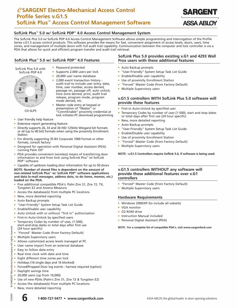
SofLink Plus™ 5.0 w/ SofLink PDP™ 4.0 Access Control Management SystemThe SofLink Plus 5.0 w/ SofLink PDP 4.0 Access Control Management Software allows simple programming and interrogation of the ProfileSeries v.G1.5 access control products. This software provides the means for fast, convenient assignment of access levels, doors, users, timezones, and management of multiple doors with full audit trail capability. Communication between the computer and lock controller is via aPDA that allows for quick and efficient program transfer and audit trail retrieval.
• Password protected• Supports 2,000 users per lock• 20,000 user name database• 2,000 event transaction history –
audit trail to include user entry, date,time, user number, access denied, passage on, passage off, auto unlock,time zone denied, print, audit trailrelease, program mode, programmode denied, etc.
• Master code entry at keypad or presentation of “Master” or“CommEnable” proximity credential atlock initiates PC download programming
• User friendly help feature• Extensive report generating feature• Directly supports 26, 33 and 34 HID 125kHz Wiegand bit formats
or all (up to 40 bit) formats when using the proximity EnrollmentStation
• For directly supporting 35 Bit Corporate 1000 Format or other formats, consult factory
• Designed for operation with Personal Digital Assistant (PDA) running Palm OS®
• PDA provides convenient (wireless) means of transferring doorinformation to and from lock using SofLink Plus™ w/ SofLink PDP™ software
• Capable of up/down loading door information for up to 50 doorsNOTE: Number of stored files is dependent on the amount of non-related SofLink Plus™ w/ SofLink PDP™ software applicationsand data (e-mail messages, address data, to do items, memos, etc.)loaded on the PDA.• Five additional compatible PDA's: Palm Zire 31, Zire 72, TX,
Tungsten E2 and Aceeca Meazura• Access the database(s) from multiple PC locations• New, more detailed reporting• Auto Backup prompts• "User-Friendly" System Setup Task List Guide• Enable/Disable user capability• Auto Unlock with or without “first in” authorization• First-in Auto-Unlock by specified users• Temporary Codes by number of uses, (1-500),
start-and-stop dates or total days after first use (24 hour specific)
• "Forced" Master Code (from Factory Default)• Multiple Supervisory users• Allows customized access levels managed at PC• User name import from an external database• Easy to follow data entry• Real time clock with date and time• Eight different time zones per lock• Holidays (16 single days and 16 blocked)• Forced/Propped Door log events - harness required (option)• Daylight savings time• 20,000 users (up from 10,000)• Use of new PDAs (Palm's Zire 31, Zire 72 & Tungsten E2)• Access the database(s) from multiple PC locations• New, more detailed reporting
• Auto Backup prompts• "User-Friendly" System Setup Task List Guide• Enable/Disable user capability• Use of proximity Enrollment Station • "Forced" Master Code (from Factory Default)• Multiple Supervisory users
v.G1.5 controllers WITH SofLink Plus 5.0 software willprovide these features• First-in Auto-Unlock by specified user• Temporary Codes by number of uses (1-500), start and stop dates
or total days after first use (24 hour specific)• New, more detailed reporting• Auto Backup prompts• "User-Friendly" System Setup Task List Guide• Enable/Disable user capability• Use of proximity Enrollment Station• "Forced" Master Code (from Factory Default)• Multiple Supervisory users
NOTE : v.G1.5 Controllers require Soflink 5.0, if software is being used.
v.G1.5 controllers WITHOUT any software will provide these additional features over v.G1controllers• “Forced” Master Code (from Factory Default)• Multiple Supervisory users
Hardware Requirements• Windows 2000/XP (to include all subsets)• VGA monitor• CD ROM drive• Instruction Manual included• Personal Digital Assistant (PDA)
NOTE : For a complete list of compatible PDA's, visit www.sargentlock.com
SofLink Plus™ 5.0 w/ SofLink PDP™ 4.0 FeaturesSofLink Plus 5.0 provides existing v.G1 and 4293 WallProx users with these additional features
CD-SLP5
SofLink Plus 5.0 withSofLink PDP 4.0
7 7/20
/07
© S
AR
GEN
T M
anu
fact
uri
ng
Co
mp
any
All
rig
hts
res
erve
d
1-800-727-5477 • www.sargentlock.com
e SARGENT Electro-Mechanical Access ControlProfile LK Series Stand Alone Access ControlProfile LU, PK & PA Series Stand Alone Access Control
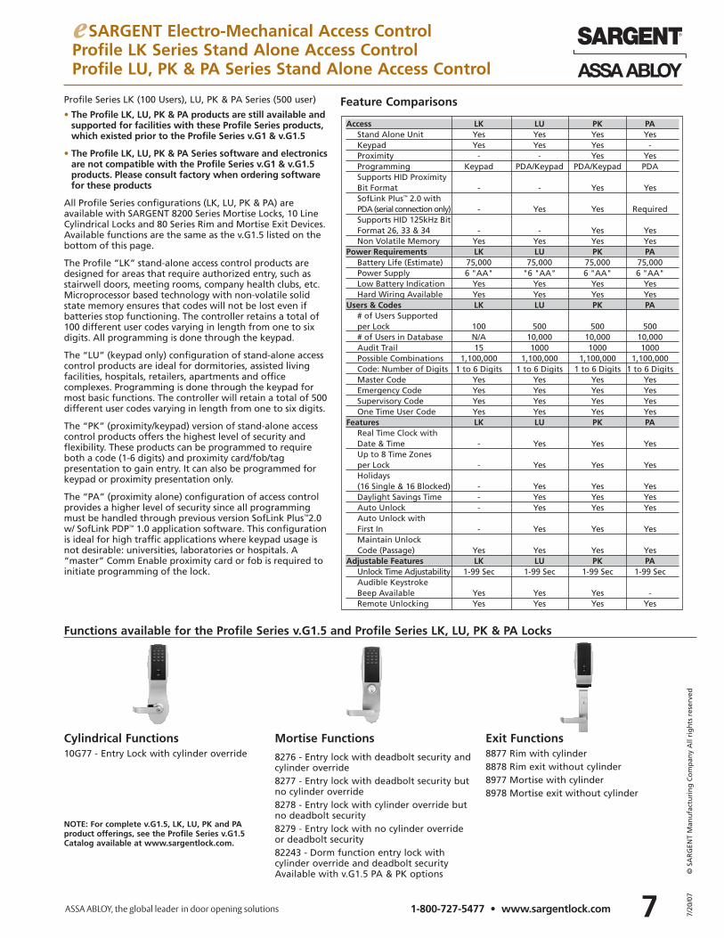
• The Profile LK, LU, PK & PA products are still available andsupported for facilities with these Profile Series products,which existed prior to the Profile Series v.G1 & v.G1.5
• The Profile LK, LU, PK & PA Series software and electronicsare not compatible with the Profile Series v.G1 & v.G1.5products. Please consult factory when ordering softwarefor these products
All Profile Series configurations (LK, LU, PK & PA) areavailable with SARGENT 8200 Series Mortise Locks, 10 LineCylindrical Locks and 80 Series Rim and Mortise Exit Devices.Available functions are the same as the v.G1.5 listed on thebottom of this page.
The Profile “LK” stand-alone access control products aredesigned for areas that require authorized entry, such asstairwell doors, meeting rooms, company health clubs, etc.Microprocessor based technology with non-volatile solidstate memory ensures that codes will not be lost even ifbatteries stop functioning. The controller retains a total of100 different user codes varying in length from one to sixdigits. All programming is done through the keypad.
The “LU” (keypad only) configuration of stand-alone accesscontrol products are ideal for dormitories, assisted livingfacilities, hospitals, retailers, apartments and officecomplexes. Programming is done through the keypad formost basic functions. The controller will retain a total of 500different user codes varying in length from one to six digits.
The “PK” (proximity/keypad) version of stand-alone accesscontrol products offers the highest level of security andflexibility. These products can be programmed to requireboth a code (1-6 digits) and proximity card/fob/tagpresentation to gain entry. It can also be programmed forkeypad or proximity presentation only.
The “PA” (proximity alone) configuration of access controlprovides a higher level of security since all programmingmust be handled through previous version SofLink Plus™2.0w/ SofLink PDP™ 1.0 application software. This configurationis ideal for high traffic applications where keypad usage isnot desirable: universities, laboratories or hospitals. A“master” Comm Enable proximity card or fob is required toinitiate programming of the lock.
Profile Series LK (100 Users), LU, PK & PA Series (500 user)
Access LK LU PK PAStand Alone Unit Yes Yes Yes YesKeypad Yes Yes Yes -Proximity - - Yes YesProgramming Keypad PDA/Keypad PDA/Keypad PDASupports HID Proximity Bit Format - - Yes YesSofLink Plus™ 2.0 withPDA (serial connection only) - Yes Yes RequiredSupports HID 125kHz BitFormat 26, 33 & 34 - - Yes YesNon Volatile Memory Yes Yes Yes Yes
Power Requirements LK LU PK PABattery Life (Estimate) 75,000 75,000 75,000 75,000Power Supply 6 "AA" "6 "AA" 6 "AA" 6 "AA"Low Battery Indication Yes Yes Yes YesHard Wiring Available Yes Yes Yes Yes
Users & Codes LK LU PK PA# of Users Supported per Lock 100 500 500 500# of Users in Database N/A 10,000 10,000 10,000Audit Trail 15 1000 1000 1000Possible Combinations 1,100,000 1,100,000 1,100,000 1,100,000Code: Number of Digits 1 to 6 Digits 1 to 6 Digits 1 to 6 Digits 1 to 6 DigitsMaster Code Yes Yes Yes YesEmergency Code Yes Yes Yes YesSupervisory Code Yes Yes Yes YesOne Time User Code Yes Yes Yes Yes
Features LK LU PK PAReal Time Clock with Date & Time - Yes Yes YesUp to 8 Time Zones per Lock - Yes Yes YesHolidays (16 Single & 16 Blocked) - Yes Yes YesDaylight Savings Time - Yes Yes YesAuto Unlock - Yes Yes YesAuto Unlock with First In - Yes Yes YesMaintain Unlock Code (Passage) Yes Yes Yes Yes
Adjustable Features LK LU PK PAUnlock Time Adjustability 1-99 Sec 1-99 Sec 1-99 Sec 1-99 SecAudible Keystroke Beep Available Yes Yes Yes -Remote Unlocking Yes Yes Yes Yes
Feature Comparisons
Cylindrical Functions Mortise Functions Exit Functions10G77 - Entry Lock with cylinder override 8276 - Entry lock with deadbolt security and
cylinder override8277 - Entry lock with deadbolt security butno cylinder override8278 - Entry lock with cylinder override butno deadbolt security8279 - Entry lock with no cylinder overrideor deadbolt security82243 - Dorm function entry lock withcylinder override and deadbolt securityAvailable with v.G1.5 PA & PK options
8877 Rim with cylinder8878 Rim exit without cylinder8977 Mortise with cylinder8978 Mortise exit without cylinder
Functions available for the Profile Series v.G1.5 and Profile Series LK, LU, PK & PA Locks
NOTE: For complete v.G1.5, LK, LU, PK and PAproduct offerings, see the Profile Series v.G1.5 Catalog available at www.sargentlock.com.
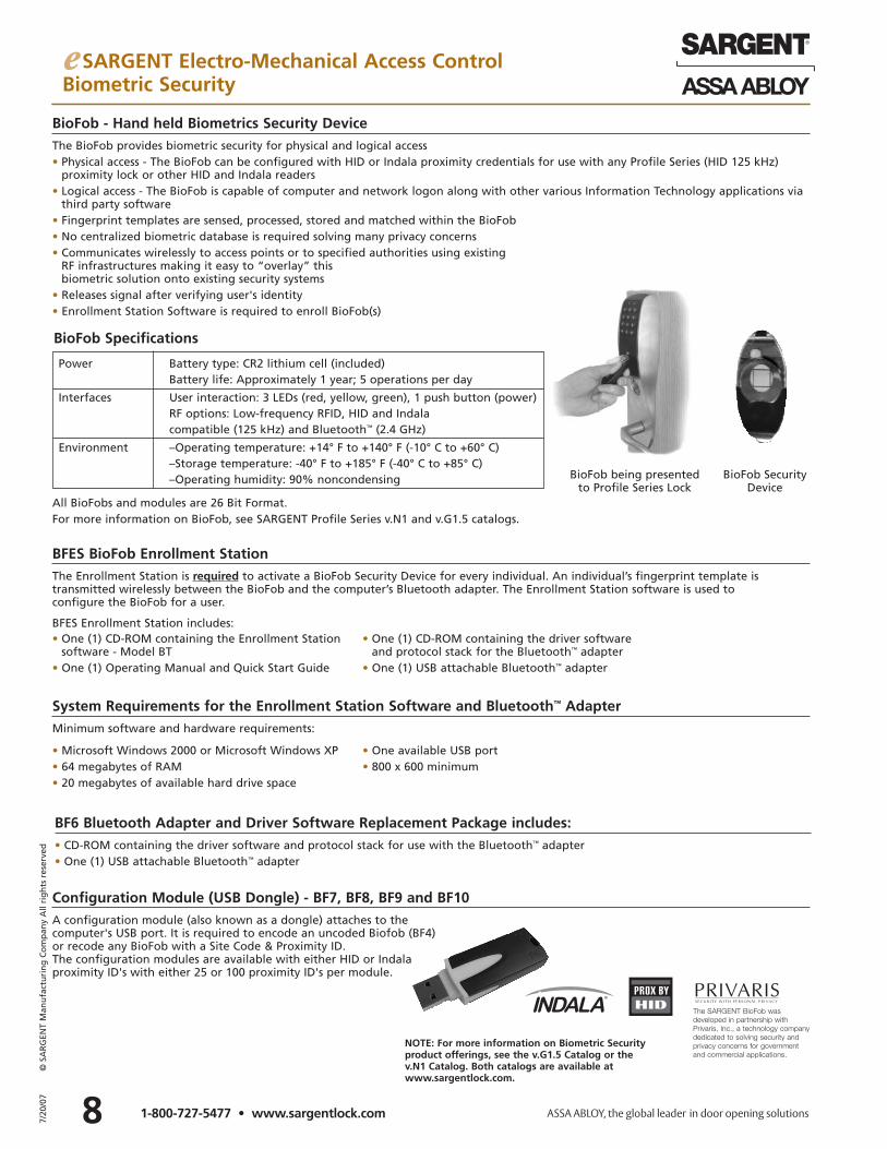
BioFob - Hand held Biometrics Security DeviceThe BioFob provides biometric security for physical and logical access• Physical access - The BioFob can be configured with HID or Indala proximity credentials for use with any Profile Series (HID 125 kHz)
proximity lock or other HID and Indala readers• Logical access - The BioFob is capable of computer and network logon along with other various Information Technology applications via
third party software• Fingerprint templates are sensed, processed, stored and matched within the BioFob• No centralized biometric database is required solving many privacy concerns• Communicates wirelessly to access points or to specified authorities using existing
RF infrastructures making it easy to “overlay” this biometric solution onto existing security systems
• Releases signal after verifying user's identity • Enrollment Station Software is required to enroll BioFob(s)
Power Battery type: CR2 lithium cell (included)Battery life: Approximately 1 year; 5 operations per day
Interfaces User interaction: 3 LEDs (red, yellow, green), 1 push button (power)RF options: Low-frequency RFID, HID and Indala compatible (125 kHz) and Bluetooth™ (2.4 GHz)
Environment –Operating temperature: +14° F to +140° F (-10° C to +60° C)–Storage temperature: -40° F to +185° F (-40° C to +85° C)–Operating humidity: 90% noncondensing
BioFob Specifications
BioFob being presentedto Profile Series Lock
BioFob Security Device
Configuration Module (USB Dongle) - BF7, BF8, BF9 and BF10A configuration module (also known as a dongle) attaches to the computer's USB port. It is required to encode an uncoded Biofob (BF4) or recode any BioFob with a Site Code & Proximity ID. The configuration modules are available with either HID or Indala proximity ID's with either 25 or 100 proximity ID's per module.
All BioFobs and modules are 26 Bit Format. For more information on BioFob, see SARGENT Profile Series v.N1 and v.G1.5 catalogs.
BFES BioFob Enrollment StationThe Enrollment Station is required to activate a BioFob Security Device for every individual. An individual’s fingerprint template is transmitted wirelessly between the BioFob and the computer’s Bluetooth adapter. The Enrollment Station software is used to configure the BioFob for a user.
BFES Enrollment Station includes:
System Requirements for the Enrollment Station Software and Bluetooth™ AdapterMinimum software and hardware requirements:
• One (1) CD-ROM containing the Enrollment Stationsoftware - Model BT
• One (1) Operating Manual and Quick Start Guide
• One (1) CD-ROM containing the driver softwareand protocol stack for the Bluetooth™ adapter
• One (1) USB attachable Bluetooth™ adapter
• Microsoft Windows 2000 or Microsoft Windows XP• 64 megabytes of RAM• 20 megabytes of available hard drive space
• One available USB port• 800 x 600 minimum
BF6 Bluetooth Adapter and Driver Software Replacement Package includes:• CD-ROM containing the driver software and protocol stack for use with the Bluetooth™ adapter• One (1) USB attachable Bluetooth™ adapter
The SARGENT BioFob was developed in partnership withPrivaris, Inc., a technology companydedicated to solving security andprivacy concerns for governmentand commercial applications.
87/20
/07
© S
AR
GEN
T M
anu
fact
uri
ng
Co
mp
any
All
rig
hts
res
erve
d
1-800-727-5477 • www.sargentlock.com
e SARGENT Electro-Mechanical Access ControlBiometric Security
NOTE: For more information on Biometric Securityproduct offerings, see the v.G1.5 Catalog or the v.N1 Catalog. Both catalogs are available at www.sargentlock.com.
e SARGENT Electro-Mechanical Access ControlProfile Series v.N1 and v.G1.5Access Control Products and Accessories
9 7/20
/07
© S
AR
GEN
T M
anu
fact
uri
ng
Co
mp
any
All
rig
hts
res
erve
d
1-800-727-5477 • www.sargentlock.com
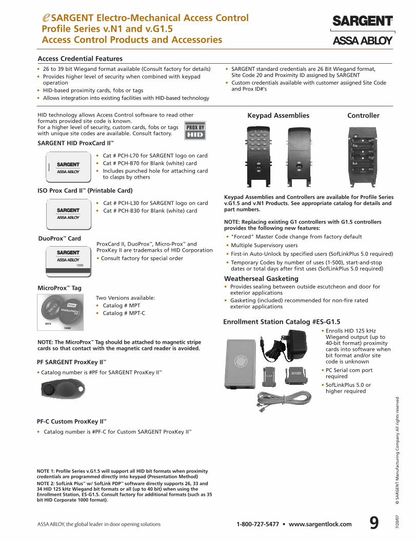
SARGENT HID ProxCard II™
• Cat # PCH-L70 for SARGENT logo on card• Cat # PCH-B70 for Blank (white) card• Includes punched hole for attaching card
to clasps by others
PF SARGENT ProxKey II™
• Catalog number is #PF for SARGENT ProxKey II™
ISO Prox Card II™ (Printable Card)
• Cat # PCH-L30 for SARGENT logo on card • Cat # PCH-B30 for Blank (white) card
DuoProx™ Card
1000
Access Credential Features
ProxCard II, DuoProx™, Micro-Prox™ andProxKey II are trademarks of HID Corporation
• Consult factory for special order
PF-C Custom ProxKey II™
• Catalog number is #PF-C for Custom SARGENT ProxKey II™
• 26 to 39 bit Wiegand format available (Consult factory for details)• Provides higher level of security when combined with keypad
operation • HID-based proximity cards, fobs or tags• Allows integration into existing facilities with HID-based technology
• SARGENT standard credentials are 26 Bit Wiegand format, Site Code 20 and Proximity ID assigned by SARGENT
• Custom credentials available with customer assigned Site Code and Prox ID#'s
HID technology allows Access Control software to read other formats provided site code is known. For a higher level of security, custom cards, fobs or tags with unique site codes are available. Consult factory.
NOTE 1: Profile Series v.G1.5 will support all HID bit formats when proximitycredentials are programmed directly into keypad (Presentation Method)NOTE 2: SofLink Plus™ w/ SofLink PDP™ software directly supports 26, 33 and34 HID 125 kHz Wiegand bit formats or all (up to 40 bit) when using theEnrollment Station, ES-G1.5. Consult factory for additional formats (such as 35bit HID Corporate 1000 format).
Weatherseal Gasketing• Provides sealing between outside escutcheon and door for
exterior applications• Gasketing (included) recommended for non-fire rated
exterior applications
Keypad Assemblies Controller
NOTE: Replacing existing G1 controllers with G1.5 controllers provides the following new features:
• "Forced" Master Code change from factory default
• Multiple Supervisory users
• First-in Auto-Unlock by specified users (SofLinkPlus 5.0 required)
• Temporary Codes by number of uses (1-500), start-and-stop dates or total days after first uses (SofLinkPlus 5.0 required)
Keypad Assemblies and Controllers are available for Profile Seriesv.G1.5 and v.N1 Products. See appropriate catalog for details andpart numbers.
Enrollment Station Catalog #ES-G1.5• Enrolls HID 125 kHz
Wiegand output (up to 40-bit format) proximitycards into software whenbit format and/or sitecode is unknown
• PC Serial com portrequired
• SofLinkPlus 5.0 or higher required
MicroProx™ Tag
Two Versions available:• Catalog # MPT• Catalog # MPT-C
NOTE: The MicroProx™ Tag should be attached to magnetic stripecards so that contact with the magnetic card reader is avoided.
107/20
/07
© S
AR
GEN
T M
anu
fact
uri
ng
Co
mp
any
All
rig
hts
res
erve
d
1-800-727-5477 • www.sargentlock.com
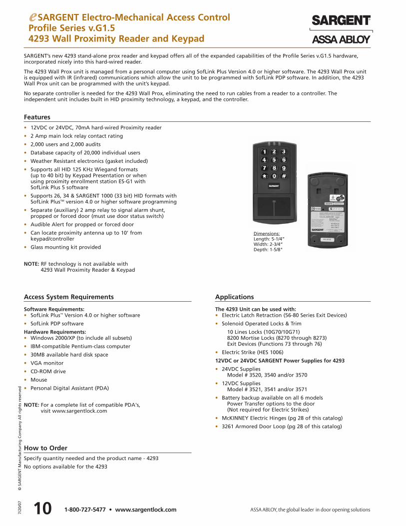
SARGENT’s new 4293 stand-alone prox reader and keypad offers all of the expanded capabilities of the Profile Series v.G1.5 hardware,incorporated nicely into this hard-wired reader.
The 4293 Wall Prox unit is managed from a personal computer using SofLink Plus Version 4.0 or higher software. The 4293 Wall Prox unitis equipped with IR (infrared) communications which allow the unit to be programmed with SofLink PDP software. In addition, the 4293Wall Prox unit can be programmed with the unit’s keypad.
No separate controller is needed for the 4293 Wall Prox, eliminating the need to run cables from a reader to a controller. The independent unit includes built in HID proximity technology, a keypad, and the controller.
• 12VDC or 24VDC, 70mA hard-wired Proximity reader
• 2 Amp main lock relay contact rating
• 2,000 users and 2,000 audits
• Database capacity of 20,000 individual users
• Weather Resistant electronics (gasket included)
• Supports all HID 125 KHz Wiegand formats (up to 40 bit) by Keypad Presentation or when using proximity enrollment station ES-G1 with SofLink Plus 5 software
• Supports 26, 34 & SARGENT 1000 (33 bit) HID formats with SofLink PlusTM version 4.0 or higher software programming
• Separate (auxiliary) 2 amp relay to signal alarm shunt, propped or forced door (must use door status switch)
• Audible Alert for propped or forced door
• Can locate proximity antenna up to 10’ from keypad/controller
• Glass mounting kit provided
NOTE: RF technology is not available with 4293 Wall Proximity Reader & Keypad
Features
Access System Requirements
Dimensions:Length: 5-1/4”Width: 2-3/4”Depth: 1-5/8"
Software Requirements:• SofLink Plus™ Version 4.0 or higher software
• SofLink PDP software
Hardware Requirements:• Windows 2000/XP (to include all subsets)
• IBM-compatible Pentium-class computer
• 30MB available hard disk space
• VGA monitor
• CD-ROM drive
• Mouse
• Personal Digital Assistant (PDA)
NOTE: For a complete list of compatible PDA's, visit www.sargentlock.com
Applications
The 4293 Unit can be used with:• Electric Latch Retraction (56-80 Series Exit Devices)
• Solenoid Operated Locks & Trim
10 Lines Locks (10G70/10G71)8200 Mortise Locks (8270 through 8273)Exit Devices (Functions 73 through 76)
• Electric Strike (HES 1006)
12VDC or 24VDC SARGENT Power Supplies for 4293
• 24VDC SuppliesModel # 3520, 3540 and/or 3570
• 12VDC SuppliesModel # 3521, 3541 and/or 3571
• Battery backup available on all 6 modelsPower Transfer options to the door (Not required for Electric Strikes)
• McKINNEY Electric Hinges (pg 28 of this catalog)
• 3261 Armored Door Loop (pg 28 of this catalog)
e SARGENT Electro-Mechanical Access ControlProfile Series v.G1.54293 Wall Proximity Reader and Keypad
How to OrderSpecify quantity needed and the product name - 4293
No options available for the 4293
11 7/20
/07
© S
AR
GEN
T M
anu
fact
uri
ng
Co
mp
any
All
rig
hts
res
erve
d
1-800-727-5477 • www.sargentlock.com
e SARGENT Electro-Mechanical Access ControlPower Supplies and Accessories
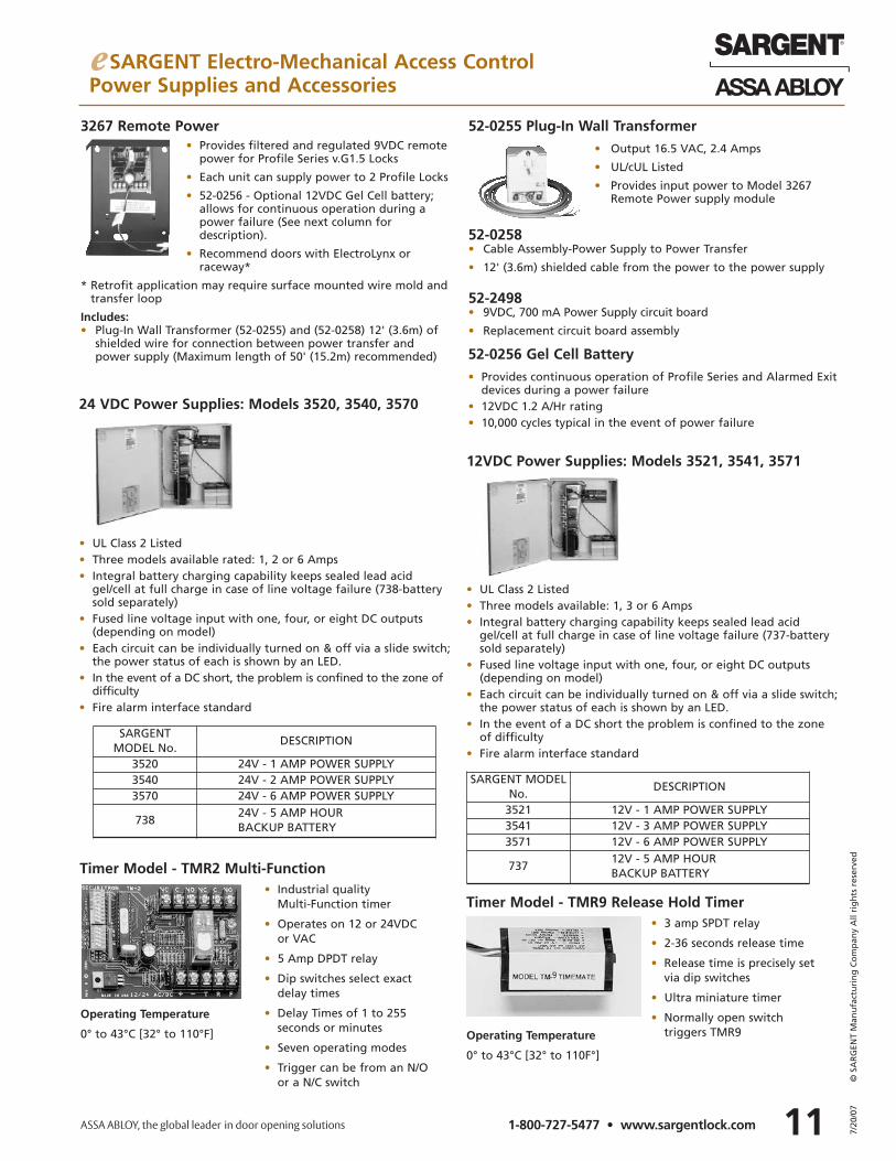
24 VDC Power Supplies: Models 3520, 3540, 3570
• UL Class 2 Listed • Three models available rated: 1, 2 or 6 Amps• Integral battery charging capability keeps sealed lead acid
gel/cell at full charge in case of line voltage failure (738-battery sold separately)
• Fused line voltage input with one, four, or eight DC outputs(depending on model)
• Each circuit can be individually turned on & off via a slide switch; the power status of each is shown by an LED.
• In the event of a DC short, the problem is confined to the zone of difficulty
• Fire alarm interface standard
Timer Model - TMR9 Release Hold Timer• 3 amp SPDT relay
• 2-36 seconds release time
• Release time is precisely setvia dip switches
• Ultra miniature timer
• Normally open switch triggers TMR9
3267 Remote Power• Provides filtered and regulated 9VDC remote
power for Profile Series v.G1.5 Locks
• Each unit can supply power to 2 Profile Locks
• 52-0256 - Optional 12VDC Gel Cell battery;allows for continuous operation during apower failure (See next column fordescription).
• Recommend doors with ElectroLynx or raceway*
* Retrofit application may require surface mounted wire mold andtransfer loop
Includes:• Plug-In Wall Transformer (52-0255) and (52-0258) 12' (3.6m) of
shielded wire for connection between power transfer andpower supply (Maximum length of 50' (15.2m) recommended)
52-0255 Plug-In Wall Transformer• Output 16.5 VAC, 2.4 Amps
• UL/cUL Listed
• Provides input power to Model 3267Remote Power supply module
52-0258• Cable Assembly-Power Supply to Power Transfer
• 12' (3.6m) shielded cable from the power to the power supply
52-2498• 9VDC, 700 mA Power Supply circuit board
• Replacement circuit board assembly
SARGENT MODELNo.
DESCRIPTION
3521 12V - 1 AMP POWER SUPPLY3541 12V - 3 AMP POWER SUPPLY3571 12V - 6 AMP POWER SUPPLY
73712V - 5 AMP HOUR BACKUP BATTERY
SARGENT MODEL No.
DESCRIPTION
3520 24V - 1 AMP POWER SUPPLY3540 24V - 2 AMP POWER SUPPLY3570 24V - 6 AMP POWER SUPPLY
73824V - 5 AMP HOUR BACKUP BATTERY
12VDC Power Supplies: Models 3521, 3541, 3571
• UL Class 2 Listed • Three models available: 1, 3 or 6 Amps• Integral battery charging capability keeps sealed lead acid
gel/cell at full charge in case of line voltage failure (737-battery sold separately)
• Fused line voltage input with one, four, or eight DC outputs(depending on model)
• Each circuit can be individually turned on & off via a slide switch; the power status of each is shown by an LED.
• In the event of a DC short the problem is confined to the zone of difficulty
• Fire alarm interface standard
Timer Model - TMR2 Multi-Function• Industrial quality
Multi-Function timer
• Operates on 12 or 24VDC or VAC
• 5 Amp DPDT relay
• Dip switches select exactdelay times
• Delay Times of 1 to 255 seconds or minutes
• Seven operating modes
• Trigger can be from an N/O or a N/C switch
Operating Temperature
0° to 43°C [32° to 110°F] Operating Temperature
0° to 43°C [32° to 110F°]
52-0256 Gel Cell Battery• Provides continuous operation of Profile Series and Alarmed Exit
devices during a power failure• 12VDC 1.2 A/Hr rating• 10,000 cycles typical in the event of power failure
127/20
/07
© S
AR
GEN
T M
anu
fact
uri
ng
Co
mp
any
All
rig
hts
res
erve
d
1-800-727-5477 • www.sargentlock.com
e SARGENT Electro-Mechanical Access ControlKeypad Operated Locks
Features
• Meets ANSI A156.3 Grade 1 requirements
• Motor-driven
• Operates with 4 “C” alkaline batteries(included)
• Typical 40,000 operations per set of batteries
• For 1-3/4" (44mm) door standard. Consultfactory for other thicknesses
• Unit can be put in ”passage only“ mode at the keypad
• Option code available to sound horn every time keypad is pressed
• External remote ”request to enter“ connector (52-2071)
• External battery input connector includedto power unit in case of battery failure
• Infrared link to optional printer (52-2069)shows last fifteen transactions
The KP Series Keypad locks are designed for openings that require stand alone, basic authorized entry capabilities. They are battery powered, motor driven, self contained locks that use a microprocessor based controller with non-volatile memory. All programming is doneat the door using the keypad with functions selected by the user according to opening requirements. Combined with the physical securityof an ANSI Grade 1 mechanical locking mechanism, (bored, mortise or exit device), these locks provide the security and functionality neededto control access to storerooms, offices, stairwells, conference rooms and restrooms.
With the cylinder override feature, the keypad lock can be readily integrated into a new or existing masterkeyed system. Lever trim and finishes are the same as those used with Profile Series Locks and with standard SARGENT mechanical locks, providing for design continuitythroughout the building.
Finishes03, 04, 09, 10, 10B, 10BL, 15, 20D, 26, 26D
LeversRefer to pages 14 and 15 for lever selections
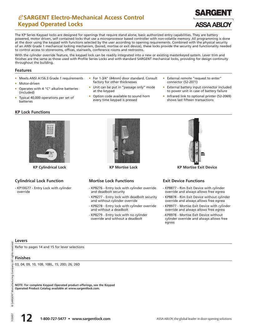
KP Mortise LockKP Cylindrical Lock KP Mortise Exit Device
Cylindrical Lock Function Mortise Lock Functions Exit Device Functions
- KP10G77 - Entry Lock with cylinder override
- KP8276 - Entry lock with cylinder overrideand deadbolt security
- KP8277 - Entry lock with deadbolt securityand without cylinder override
- KP8278 - Entry lock with cylinder overrideand without a deadbolt
- KP8279 - Entry lock with no cylinder override and without a deadbolt
- KP8877 - Rim Exit Device with cylinderoverride and always allows free egress
- KP8878 - Rim Exit Device without cylinderoverride and always allows free egress
- KP8977 - Mortise Exit Device with cylinderoverride and always allows free egress
-KP8978 - Mortise Exit Device without cylinder override and always allows freeegress
KP Lock Functions
NOTE: For complete Keypad Operated product offerings, see the KeypadOperated Product Catalog available at www.sargentlock.com.
e SARGENT Electro-Mechanical Access ControlSolenoid Controlled Products & Monitoring Options
13 7/20
/07
© S
AR
GEN
T M
anu
fact
uri
ng
Co
mp
any
All
rig
hts
res
erve
d
1-800-727-5477 • www.sargentlock.com
SARGENT's hardwired solenoid operated locks allow for remote locking and unlocking of the trim. They are designed for intermittent and continuous duty use. When used with a concealed circuit hinge (back cover) with ElectroLynx, all wires are hidden in the door toenhance security and maintain aesthetic appeal. All solenoid controlled products and monitoring options are supplied with ElectroLynxconnectors to simplify the installation process. Solenoid operated products are Fail Safe (power off, unlocks trim) or Fail Secure (power off,locks trim). Solenoids are UL tested for cycle life, low operating temperature, shock hazard, and fire hazard qualifications.
Electrical Requirements:Voltage: 12VDC or 24VDC Regulated. Full wave rectification installed inside the lockbody for AC input (12 or 24 volt) applicationsCurrent: .25A at 24VDC or .5A at 12VDCOperating Temp.: Max. 151°F (66°C)
Min –31°F (-35°C)UL and CUL listed for use on Fire DoorsNOTE: Repeated operation at voltage exceeding +/- 10% is not recommended
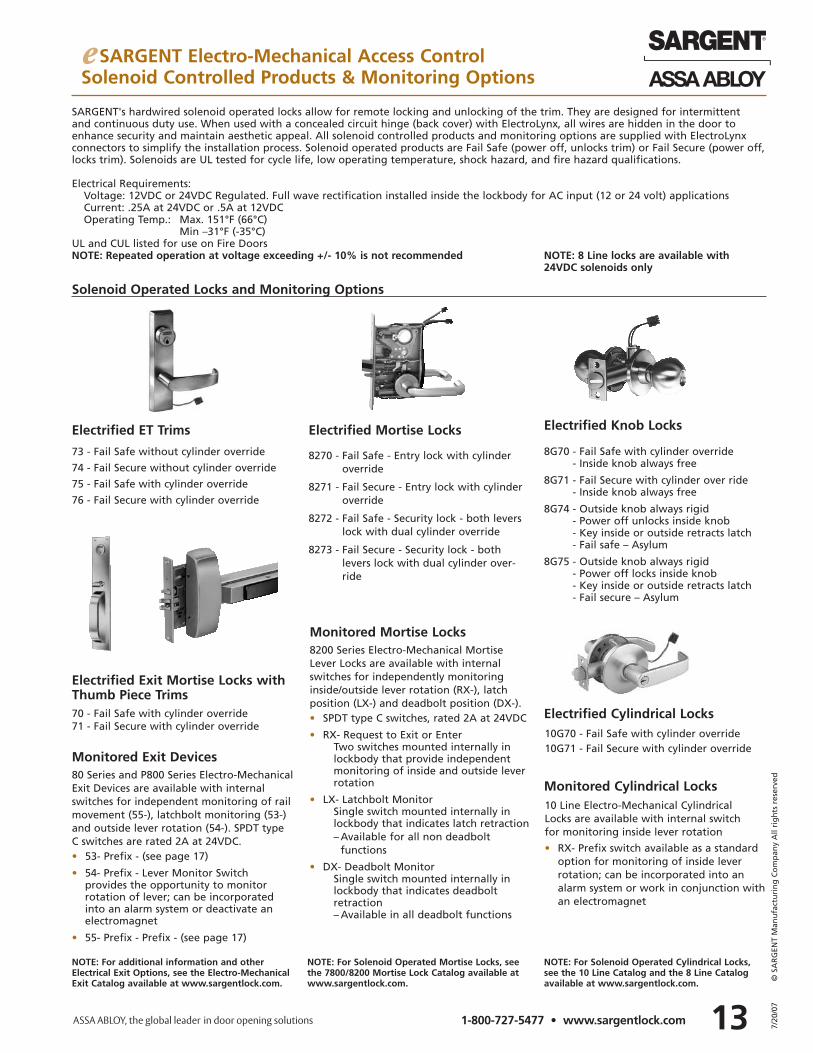
Solenoid Operated Locks and Monitoring Options
Electrified ET Trims Electrified Mortise Locks Electrified Knob Locks
Electrified Cylindrical Locks
Monitored Cylindrical Locks
73 - Fail Safe without cylinder override
74 - Fail Secure without cylinder override
75 - Fail Safe with cylinder override
76 - Fail Secure with cylinder override
8270 - Fail Safe - Entry lock with cylinderoverride
8271 - Fail Secure - Entry lock with cylinderoverride
8272 - Fail Safe - Security lock - both leverslock with dual cylinder override
8273 - Fail Secure - Security lock - bothlevers lock with dual cylinder over-ride
80 Series and P800 Series Electro-MechanicalExit Devices are available with internalswitches for independent monitoring of railmovement (55-), latchbolt monitoring (53-)and outside lever rotation (54-). SPDT typeC switches are rated 2A at 24VDC.• 53- Prefix - (see page 17)
• 54- Prefix - Lever Monitor Switch provides the opportunity to monitorrotation of lever; can be incorporatedinto an alarm system or deactivate anelectromagnet
• 55- Prefix - Prefix - (see page 17)
8200 Series Electro-Mechanical MortiseLever Locks are available with internalswitches for independently monitoringinside/outside lever rotation (RX-), latchposition (LX-) and deadbolt position (DX-).• SPDT type C switches, rated 2A at 24VDC
• RX- Request to Exit or EnterTwo switches mounted internally inlockbody that provide independentmonitoring of inside and outside leverrotation
• LX- Latchbolt MonitorSingle switch mounted internally inlockbody that indicates latch retraction– Available for all non deadbolt
functions
• DX- Deadbolt MonitorSingle switch mounted internally in lockbody that indicates deadbolt retraction– Available in all deadbolt functions
8G70 - Fail Safe with cylinder override- Inside knob always free
8G71 - Fail Secure with cylinder over ride- Inside knob always free
8G74 - Outside knob always rigid- Power off unlocks inside knob- Key inside or outside retracts latch- Fail safe – Asylum
8G75 - Outside knob always rigid - Power off locks inside knob- Key inside or outside retracts latch- Fail secure – Asylum
10G70 - Fail Safe with cylinder override10G71 - Fail Secure with cylinder override
10 Line Electro-Mechanical Cylindrical Locks are available with internal switch for monitoring inside lever rotation
• RX- Prefix switch available as a standardoption for monitoring of inside leverrotation; can be incorporated into analarm system or work in conjunction withan electromagnet
NOTE: For additional information and otherElectrical Exit Options, see the Electro-MechanicalExit Catalog available at www.sargentlock.com.
NOTE: For Solenoid Operated Mortise Locks, seethe 7800/8200 Mortise Lock Catalog available atwww.sargentlock.com.
NOTE: For Solenoid Operated Cylindrical Locks,see the 10 Line Catalog and the 8 Line Catalogavailable at www.sargentlock.com.
NOTE: 8 Line locks are available with24VDC solenoids only
Electrified Exit Mortise Locks withThumb Piece Trims
Monitored Exit Devices
Monitored Mortise Locks
70 - Fail Safe with cylinder override71 - Fail Secure with cylinder override
147/20
/07
© S
AR
GEN
T M
anu
fact
uri
ng
Co
mp
any
All
rig
hts
res
erve
d
1-800-727-5477 • www.sargentlock.com
e SARGENT Electro-Mechanical Access ControlLever Trim Designs
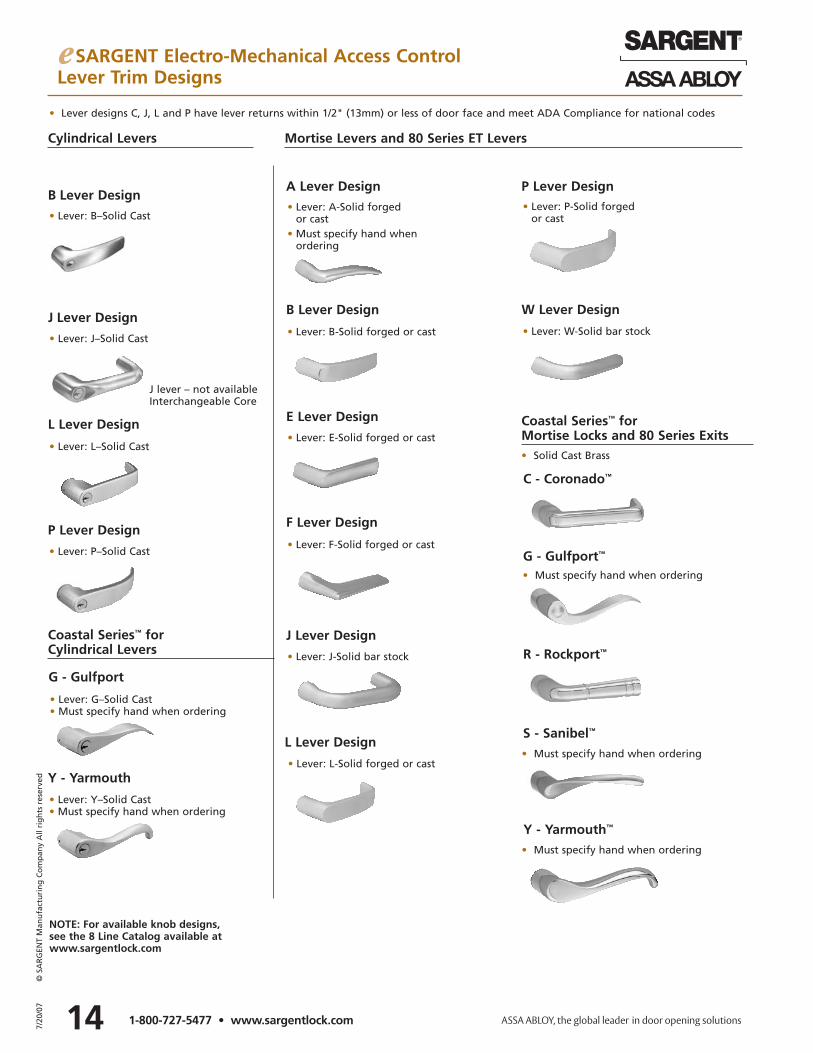
• Lever: L-Solid forged or cast
• Lever designs C, J, L and P have lever returns within 1/2" (13mm) or less of door face and meet ADA Compliance for national codes
L Lever Design
P Lever Design
• Lever: L–Solid Cast
Y - Yarmouth
• Lever: P–Solid Cast
B Lever Design
J Lever Design
• Lever: B–Solid Cast
G - Gulfport
• Lever: J–Solid Cast
J lever – not availableInterchangeable Core
• Lever: G–Solid Cast• Must specify hand when ordering
• Lever: Y–Solid Cast• Must specify hand when ordering
NOTE: For available knob designs,see the 8 Line Catalog available atwww.sargentlock.com
Cylindrical Levers Mortise Levers and 80 Series ET Levers
F Lever Design
J Lever Design
• Lever: F-Solid forged or cast
B Lever Design
• Lever: J-Solid bar stock
A Lever Design
E Lever Design
• Lever: A-Solid forged or cast
• Must specify hand whenordering
L Lever Design
• Lever: E-Solid forged or cast
• Lever: B-Solid forged or cast
W Lever Design
P Lever Design• Lever: P-Solid forged
or cast
• Lever: W-Solid bar stock
Coastal Series™ for Mortise Locks and 80 Series Exits
• Must specify hand when ordering
• Must specify hand when ordering
S - Sanibel™
C - Coronado™
R - Rockport™
Y - Yarmouth™
G - Gulfport™
Coastal Series™ for Cylindrical Levers
• Solid Cast Brass
• Must specify hand when ordering
15 7/20
/07
© S
AR
GEN
T M
anu
fact
uri
ng
Co
mp
any
All
rig
hts
res
erve
d
1-800-727-5477 • www.sargentlock.com
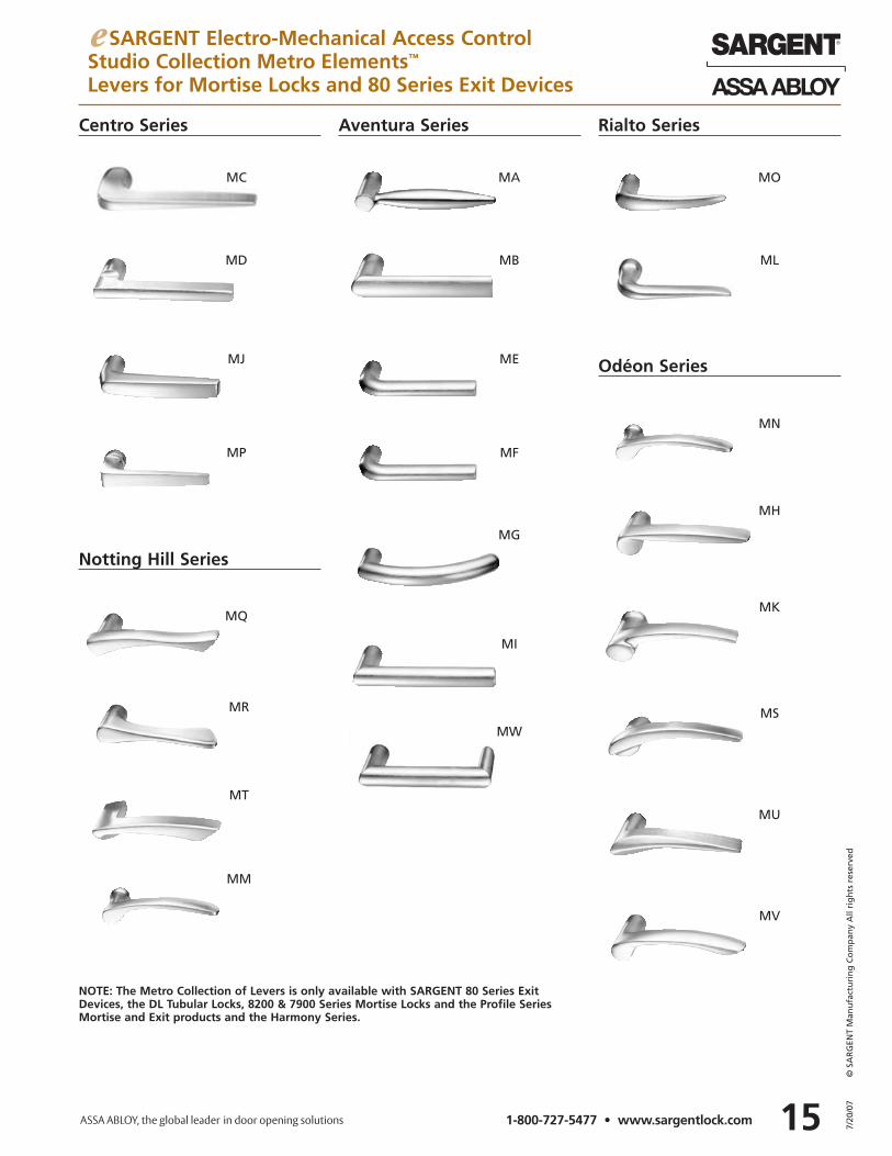
e SARGENT Electro-Mechanical Access ControlStudio Collection Metro Elements™
Levers for Mortise Locks and 80 Series Exit Devices
Rialto Series
MO
ML
MQ
MR
MT
MM
MC
MD
MJ
MP
Centro Series Aventura Series
MN
MH
MK
MS
MU
MV
Odéon Series
Notting Hill Series
MA
MB
ME
MF
MG
MI
MW
NOTE: The Metro Collection of Levers is only available with SARGENT 80 Series ExitDevices, the DL Tubular Locks, 8200 & 7900 Series Mortise Locks and the Profile SeriesMortise and Exit products and the Harmony Series.
167/20
/07
© S
AR
GEN
T M
anu
fact
uri
ng
Co
mp
any
All
rig
hts
res
erve
d
1-800-727-5477 • www.sargentlock.com
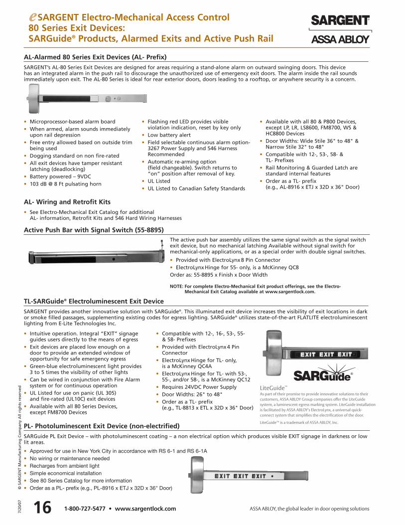
TL-SARGuide® Electroluminescent Exit DeviceSARGENT provides another innovative solution with SARGuide®. This illuminated exit device increases the visibility of exit locations in darkor smoke filled passages, supplementing existing codes for egress lighting. SARGuide® utilizes state-of-the-art FLATLITE electroluminescentlighting from E-Lite Technologies Inc.
• Intuitive operation. Integral “EXIT” signageguides users directly to the means of egress
• Exit devices are placed low enough on a door to provide an extended window ofopportunity for safe emergency egress
• Green-blue electroluminescent light provides 3 to 5 times the visibility of other lights
• Can be wired in conjunction with Fire Alarmsystem or for continuous operation
• UL Listed for use on panic (UL 305) and fire-rated (UL10C) exit devices
• Available with all 80 Series Devices, except FM8700 Devices
• Compatible with 12-, 16-, 53-, 55- & 58- Prefixes
• Provided with ElectroLynx 4 Pin Connector
• ElectroLynx Hinge for TL- only, is a McKinney QC4A
• ElectroLynx Hinge for TL- with 53-, 55-, and/or 58-, is a McKinney QC12
• Requires 24VDC Power Supply• Door Widths: 26" to 48"• Order as a TL- prefix
(e.g., TL-8813 x ETL x 32D x 36" Door)
AL-Alarmed 80 Series Exit Devices (AL- Prefix)SARGENT’s AL-80 Series Exit Devices are designed for areas requiring a stand-alone alarm on outward swinging doors. This device has an integrated alarm in the push rail to discourage the unauthorized use of emergency exit doors. The alarm inside the rail soundsimmediately upon exit. The AL-80 Series is ideal for rear exterior doors, doors leading to a rooftop, or anywhere security is a concern.
PL- Photoluminescent Exit Device (non-electrified)SARGuide PL Exit Device – with photoluminescent coating – a non electrical option which produces visible EXIT signage in darkness or lowlit areas.
• Approved for use in New York City in accordance with RS 6-1 and RS 6-1A• No wiring or maintenance needed• Recharges from ambient light• Simple economical installation• See 80 Series Catalog for more information• Order as a PL- prefix (e.g., PL-8916 x ETJ x 32D x 36" Door)
• Microprocessor-based alarm board• When armed, alarm sounds immediately
upon rail depression• Free entry allowed based on outside trim
being used• Dogging standard on non fire-rated• All exit devices have tamper resistant
latching (deadlocking)• Battery powered – 9VDC• 103 dB @ 8 Ft pulsating horn
• Flashing red LED provides visible violation indication, reset by key only
• Low battery alert• Field selectable continuous alarm option-
3267 Power Supply and 546 HarnessRecommended
• Automatic re-arming option (field changeable). Switch returns to “on” position after removal of key.
• UL Listed• UL Listed to Canadian Safety Standards
• Available with all 80 & P800 Devices,except LP, LR, LS8600, FM8700, WS &HC8800 Devices
• Door Widths: Wide Stile 36" to 48" &Narrow Stile 32" to 48"
• Compatible with 12-, 53-, 58- & TL- Prefixes
• Rail Monitoring & Guarded Latch arestandard internal features
• Order as a TL- prefix (e.g., AL-8916 x ETJ x 32D x 36" Door)
The active push bar assembly utilizes the same signal switch as the signal switchexit device, but no mechanical latching Available without signal switch formechanical-only applications, or as a special order with double signal switches.
• Provided with ElectroLynx 8 Pin Connector• ElectroLynx Hinge for 55- only, is a McKinney QC8Order as: 55-8895 x Finish x Door Width
Active Push Bar with Signal Switch (55-8895)
AL- Wiring and Retrofit Kits• See Electro-Mechanical Exit Catalog for additional
AL- information, Retrofit Kits and 546 Hard Wiring Harnesses
e SARGENT Electro-Mechanical Access Control80 Series Exit Devices:SARGuide® Products, Alarmed Exits and Active Push Rail
NOTE: For complete Electro-Mechanical Exit product offerings, see the Electro-Mechanical Exit Catalog available at www.sargentlock.com.
LiteGuide™
As part of their promise to provide innovative solutions to their customers, ASSA ABLOY Group companies offer the LiteGuide system, a luminescent egress marking system. LiteGuide installationis facilitated by ASSA ABLOY’s ElectroLynx, a universal quick-connect system that simplifies the electrification of the door.
LiteGuideTM is a trademark of ASSA ABLOY, Inc.
17 7/20
/07
© S
AR
GEN
T M
anu
fact
uri
ng
Co
mp
any
All
rig
hts
res
erve
d
1-800-727-5477 • www.sargentlock.com
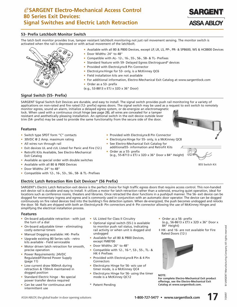
SARGENT Signal Switch Exit Devices are durable, and easy to install. The signal switch provides push rail monitoring for a variety of applications on non-rated and fire rated (12- prefix) egress doors. The signal switch may be used as a request to exit switch to remotelymonitor egress, sound an alarm, initialize a delayed egress system, or de-energize an electromagneticlock. When used with a continuous circuit hinge (see page 28), all wires are concealed for a tamperresistant and aesthetically pleasing installation. An optional switch in the exit device outside levertrim (54- prefix) may be used to provide the same functionality from the secure side of the door.
Features
Electric Latch Retraction Rim Exit Devices* (56 Prefix)SARGENT's Electric Latch Retraction exit device is the perfect choice for high traffic egress doors that require access control. This non-handedexit device rail is durable and easy to install. It utilizes a motor for latch retraction rather than a solenoid, ensuring quiet operation, ideal forlocations such as conference rooms, theaters and libraries. Once retracted the door functions in a push/pull manner. The 56- exit device can bedogged for momentary ingress and egress and is commonly used in conjunction with an automatic door operator. The device can be doggedcontinuously on fire rated devices tied into the building's fire detection system. When de-energized, the push becomes undogged and relocksthe door. 56- Rails are shipped with both an ElectroLynx8- Pin connectors and 4- Pin connector allowing the use of McKinney Hinges and simplifying the electrical installation process.
• Switch type SPDT form “C” contacts• 30VDC @ 2 Amp. maximum rating• All wires run through rail• Exit devices UL and cUL Listed for Panic and Fire (12-)• Retrofit Kits Available, See Electro-Mechanical
Exit Catalog• Available as special order with double switches• Available with all 80 & P800 Devices• Door Widths: 24" to 48"• Compatible with 12-, 16-, 53-, 56-, 58- & TL- Prefixes
• Provided with ElectroLynx 8 Pin Connector• ElectroLynx Hinge for 55- only, is a McKinney QC8• See Electro-Mechanical Exit Catalog for
additional55- information and Retrofit Kits• Order as a 55- prefix
(e.g., 55-8713 x ETJ x 32D x 36" Door x 84" Height)
855 Switch Kit
e SARGENT Electro-Mechanical Access Control80 Series Exit Devices:Signal Switches and Electric Latch Retraction
Features• On-board adjustable retraction - with just
the turn of a dial• On-board adjustable timer - eliminating
costly external timers• Manual Dogging available: HK- Prefix• Upgrade existing 80 Series rails - retro
kits available - Field serviceable• Motor driven latch retraction for smooth,
precise operation• Power Requirements: 24VDC
Regulated/Filtered Power Supply (page 11)
• Low current draw 900mA during retraction & 150mA maintained indogged position
• Standard Electric hinge - No special power transfer device required
• Can be used for continuous and intermittent use
• UL Listed for Class II Circuitry• Optional signal switch (55-) is available
to monitor push rail status, indicating rail activity or when unit is dogged andundogged
• Available for all 80 & P800 Devices,except FM8700
• Door Widths: 26" to 48"• Compatible with 12-, 16-*, 53-, 55-, TL- &
HK-‡ Prefixes• Provided with ElectroLynx 8 Pin & 4 Pin
Connectors• ElectroLynx Hinge for 56- w/o use of
timer mode, is a McKinney QC4• ElectroLynx Hinge for 56- using the timer
mode is a McKinney QC12
* Patent Pending
• Order as a 56- prefix(e.g., 56-8613 x ETJ x 32D x 36" Door x84" Height)
‡ HK- and 16- are not available for FireRated Doors (12-)
The latch bolt monitor provides true, tamper resistant latchbolt monitoring not just rail movement sensing. The monitor switch is activated when the rail is depressed or with actual movement of the latchbolt.
53- Prefix Latchbolt Monitor Switch
• Available with all 80 & P800 Devices, except LP, LR, LS, PP-, PR- & SP8600, WS & HC8800 Devices• Door Widths: 24" to 48"• Compatible with AL- 12-, 16-, 55-, 56-, 58- & TL- Prefixes• Standard feature with 59- Delayed Egress Electroguard® devices• Provided with ElectroLynx 8 Pin Connector• ElectroLynx Hinge for 53- only, is a McKinney QC6• Field installation kits are not available• For additional information, Electro-Mechanical Exit Catalog at www.sargentlock.com• Order as a 53- prefix(e.g., 53-8813 x ETJ x 32D x 36" Door)
NOTE: For complete Electro-Mechanical Exit product offerings, see the Electro-Mechanical ExitCatalog at www.sargentlock.com.
Signal Switch (55- Prefix)
187/20
/07
© S
AR
GEN
T M
anu
fact
uri
ng
Co
mp
any
All
rig
hts
res
erve
d
1-800-727-5477 • www.sargentlock.com
e SARGENT Electro-Mechanical Access Control80 Series Exit Devices:Delayed Egress and Electromagnetic Locks
• Hold door closed with 1200 lbs. of direct holding force
• Used for push or pull applications
• Stainless steel case
• Self-aligning armature
• Hardened machine screws for mounting
• 10' integral cable for easy wiring
• Bond sensor standard
• Internal electronics
• .250 amp @ 12VDC, .125 amp @ 24VDC
• For use on exterior and interior openings
• Single and double door applications
• Accessories available for various frame conditions
• UL Listed, Auxiliary Lock and Releasing Device
• UL Recognized for Special Locking Arrangements
• Accepted for City of New York, Department of Buildings
• Temperature range: -40°F to +140°F (-40°C to +60°C)
• Fail safe operation
• Finishes: 28, 32D, EB, ED
Electromagnets for Various Applications
Electromagnetic Locks: Available to be used with 57- Exits or Other Applications
1584 - Push Application - Single Door
• Metal dress covers supplied for 28, EB and ED finishes
• 1584 – 32D only
• 1584H – Includes dress cover for 28, EB and ED finishes
Order as:
1584 or 1584H x Finish
1585 - Push Application - Double Door
• Two electromagnetic locks with sensor
• 1585 – 32D only
• 1585J – includes 18" wide dress cover for2 locks in 28, EB and ED finishes standard
Order as:
1585 or 1585J x Finish
1586 - Pull Application - Single Door
• Electromagnetic lock mounted on in swinging side of the door to protect it from physical assault
• “Z” bracket with cover in 28, EB and ED finishes supplied standard
1587 – Pull Application – Double Door• Two electromagnetic locks with sensor
• Two “Z” brackets with covers in28, EB and ED finishes supplied standard
Order as:
1586 x Finish for Single Door Applicationsor1587 x Finish for Double Door Applications
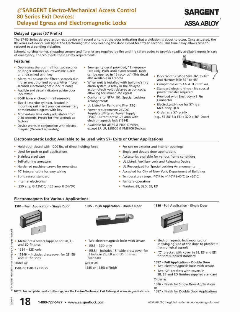
Delayed Egress (57 Prefix)The 57-80 Series delayed action exit device will sound a horn at the door indicating that a violation is about to occur. Once actuated, the80 Series exit device will signal the Electromagnetic Lock keeping the door closed for fifteen seconds. This time delay allows time torespond to a pending violation.
Schools, nursing homes, shopping centers and libraries are required by fire and life safety codes to provide readily available egress in caseof emergency. The 57- meets these safety requirements.
Features
• Depressing the push rail for two secondsor longer initiates an irreversible alarmuntil disarmed with key
• Alarm rail sounds for fifteen seconds dur-ing an unauthorized egress. After fifteenseconds electromagnetic lock releases
• Audible and visual indicators advise doorlock status
• 80dB horn enclosed in rail assembly• Size 41 mortise cylinder, located in
mounting rail insert provides momentaryor maintained egress with key
• Momentary time delay adjustable from 0-30 seconds. Preset for five seconds atfactory
• Device works in conjunction with electro-magnet (Ordered separately)
• Emergency decal provided, “EmergencyExit Only. Push until alarm sounds. Doorcan be opened in 15 seconds” (This decalalso available in French)
• When unit is installed with building's fire alarm system, a relay in the delayed action circuit voids delayed action cycle, allowing for immediate egress
• Conforms to NFPA 101, Special LockingArrangements
• UL Listed for Panic and Fire (12-)• Power requirements: 24VDC
Regulated/Filtered Power Supply (3540) Current draw: .25 amp with electromagnetic lock (1584)
• Available for all 80 & P800 Devices,except LP, LR, LS8600 & FM8700 Devices
• Door Widths: Wide Stile 36" to 48" and Narrow Stile 32" to 48"
• Compatible with 12- & TL- Prefixes• Standard electric hinge - No special
power transfer required• Provided with ElectroLynx 8 Pin
Connector• ElectroLynx Hinge for 57- is a
McKinney QC8• Order as a 57- prefix(e.g., 57-8813 x ETJ x 32D x 36" Door)
NOTE: For complete product offerings, see the Electro-Mechanical Exit Catalog at www.sargentlock.com.
191-800-727-5477 • www.sargentlock.com
e SARGENT Electro-Mechanical Access Control80 Series Exit Devices:Electric Dogging and Electroguard™ Delayed Egress
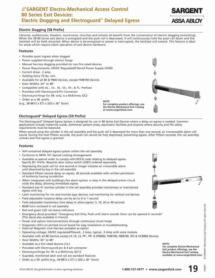
Electric Dogging (58 Prefix) Libraries, auditoriums, theaters, courtrooms, churches and schools all benefit from the convenience of electric dogging (unlocking).When the 58-80 Series exit device is energized and the push rail is depressed, it will continuously hold the push rail down and thelatch(es) will be held retracted. When device is de-energized or power is interrupted, the latch(es) will extend. This feature is ideal for areas which require silent operation of exit device hardware.
Electroguard® Delayed Egress (59 Prefix)The Electroguard® Delayed Egress System is designed for use in 80 Series Exit Devices where a delay on egress is needed. Commonapplications include maternity wards, Alzheimer patient areas, psychiatric facilities and airports where security and life safetyrequirements must be balanced.When armed using the cylinder in the rail assembly and the push rail is depressed for more than one second, an irreverseable alarm willsound. During the next fifteen seconds, the push rail cannot be fully depressed, preventing egress. After fifteen seconds, the rail assemblyunlocks and free egress is granted.
Features• Self-contained delayed egress system within the rail assembly• Conforms to NFPA 101 Special Locking Arrangements• Available as special order to comply with BOCA code relating to delayed egress.
Specify BC- Prefix. Requires door status switch (3287) ordered separately.• Depressing the push rail for one second or longer initiates an irreversible alarm
until disarmed by key in the rail assembly• Standard fifteen second delay on egress, 30 seconds available with written permission
of Authority having Jurisdiction• When integrated with building’s fire alarm system, a relay in the delayed action circuit
voids the delay, allowing immediate egress• Standard size 41 mortise cylinder in the rail assembly provides momentary or maintained
egress with key• Latch monitoring for rim and mortise type devices; rod monitoring for vertical rod devices• Field adjustable nuisance delay can be set to 0 or 1 second • Field adjustable momentary time delay to allow egress: 5, 10, 20 or 40 seconds• 80dB horn enclosed in rail assembly• Red and green LED rail status indicators• Emergency decal provided: “Emergency Exit Only. Push until alarm sounds. Door can be opened in seconds"
(This decal also available in French)• Power and option interconnections through continuous circuit hinge• Diagnostic LED's on printed circuit board for easy installation or troubleshooting• External Magnetic Lock Harness available as option• Operating voltage: 24VDC regulated/filtered, .2 Amp. typical, .5 Amp with voice module• Available with all 80 Devices except LP, LR, LS, PP-, PR- & SP8600, FM8700, NB8700, WS & HC8800 Devices• Door Widths: 36" to 48"• Available as a fire rated devices (12-)• Provided with ElectroLynx 8 pin & 4 pin connector• ElectroLynx Hinge for 59- is a McKinney QC12• Guarded, monitored latch and rail are standard features• Order as a 59- prefix (e.g., 59-8813 x ETJ x 32D x 36" Door)
Features• Provides quiet ingress when dogged• Power supplied through electric hinge• Manual hex key dogging provided on non-fire rated devices• Power Requirements: 24VDC Regulated/Filtered Power Supply (3540)• Current draw: .2 amp.• Holding force 70 lbs. min.• Available for all 80 & P800 Devices, except FM8700 Devices• Door Widths: 24" to 48"• Compatible with AL-, 12-, 16-, 53-, 55-, & TL- Prefixes• Provided with ElectroLynx 8 Pin Connector• ElectroLynx Hinge for 58- only, is a McKinney QC2• Order as a 58- prefix (e.g., 58-8813 x ETJ x 32D x 36" Door)
NOTE: For complete Electro-MechanicalExit product offerings, see the Electro-Mechanical Exit Catalogavailable at www.sargentlock.com.
NOTE: For complete product offerings, seethe Electro-Mechanical Exit Catalogat www.sargentlock.com.
7/20
/07
© S
AR
GEN
T M
anu
fact
uri
ng
Co
mp
any
All
rig
hts
res
erve
d
2-5/8"
8-3/8"
2"
6"6" 2-5/8"
8-3/8"
2"
MAGNET ONDOOR ANDALARM ONJAMB
TOP JAMB ORSIDE JAMB
ALARM ONDOOR ANDMAGNET ONJAMB
62"RECOMMENDEDHEIGHT
207/20
/07
© S
AR
GEN
T M
anu
fact
uri
ng
Co
mp
any
All
rig
hts
res
erve
d
1-800-727-5477 • www.sargentlock.com
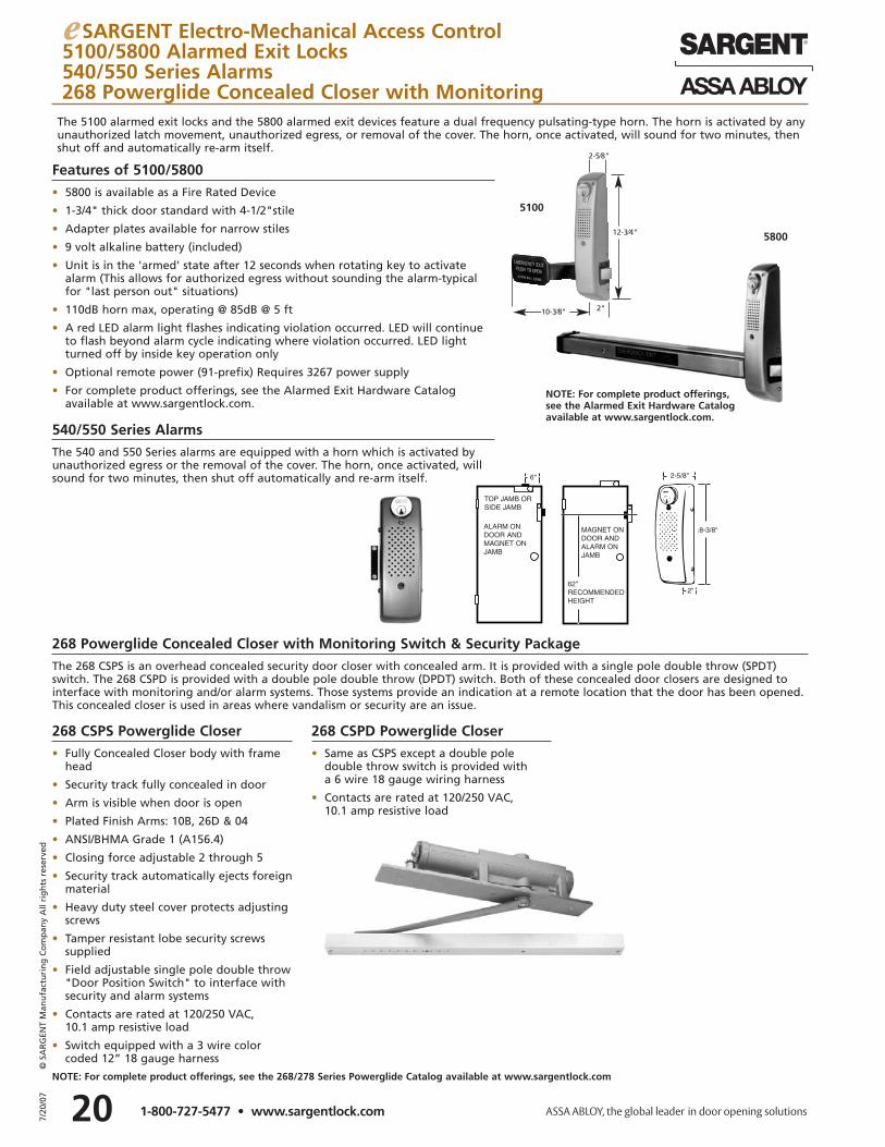
e SARGENT Electro-Mechanical Access Control5100/5800 Alarmed Exit Locks540/550 Series Alarms268 Powerglide Concealed Closer with Monitoring
Features of 5100/5800• 5800 is available as a Fire Rated Device
• 1-3/4" thick door standard with 4-1/2"stile
• Adapter plates available for narrow stiles
• 9 volt alkaline battery (included)
• Unit is in the 'armed' state after 12 seconds when rotating key to activatealarm (This allows for authorized egress without sounding the alarm-typicalfor "last person out" situations)
• 110dB horn max, operating @ 85dB @ 5 ft
• A red LED alarm light flashes indicating violation occurred. LED will continueto flash beyond alarm cycle indicating where violation occurred. LED lightturned off by inside key operation only
• Optional remote power (91-prefix) Requires 3267 power supply
• For complete product offerings, see the Alarmed Exit Hardware Catalog available at www.sargentlock.com.
268 CSPS Powerglide Closer• Fully Concealed Closer body with frame
head
• Security track fully concealed in door
• Arm is visible when door is open
• Plated Finish Arms: 10B, 26D & 04
• ANSI/BHMA Grade 1 (A156.4)
• Closing force adjustable 2 through 5
• Security track automatically ejects foreignmaterial
• Heavy duty steel cover protects adjustingscrews
• Tamper resistant lobe security screws supplied
• Field adjustable single pole double throw"Door Position Switch" to interface withsecurity and alarm systems
• Contacts are rated at 120/250 VAC, 10.1 amp resistive load
• Switch equipped with a 3 wire colorcoded 12” 18 gauge harness
268 CSPD Powerglide Closer• Same as CSPS except a double pole
double throw switch is provided with a 6 wire 18 gauge wiring harness
• Contacts are rated at 120/250 VAC, 10.1 amp resistive load
5800
5100
12-3⁄4"
2"10-3⁄8"
The 5100 alarmed exit locks and the 5800 alarmed exit devices feature a dual frequency pulsating-type horn. The horn is activated by anyunauthorized latch movement, unauthorized egress, or removal of the cover. The horn, once activated, will sound for two minutes, thenshut off and automatically re-arm itself.
2-5⁄8"
NOTE: For complete product offerings, see the 268/278 Series Powerglide Catalog available at www.sargentlock.com
NOTE: For complete product offerings,see the Alarmed Exit Hardware Catalogavailable at www.sargentlock.com.
268 Powerglide Concealed Closer with Monitoring Switch & Security PackageThe 268 CSPS is an overhead concealed security door closer with concealed arm. It is provided with a single pole double throw (SPDT)switch. The 268 CSPD is provided with a double pole double throw (DPDT) switch. Both of these concealed door closers are designed tointerface with monitoring and/or alarm systems. Those systems provide an indication at a remote location that the door has been opened. This concealed closer is used in areas where vandalism or security are an issue.
540/550 Series AlarmsThe 540 and 550 Series alarms are equipped with a horn which is activated by unauthorized egress or the removal of the cover. The horn, once activated, will sound for two minutes, then shut off automatically and re-arm itself.
21 7/20
/07
© S
AR
GEN
T M
anu
fact
uri
ng
Co
mp
any
All
rig
hts
res
erve
d
1-800-727-5477 • www.sargentlock.com
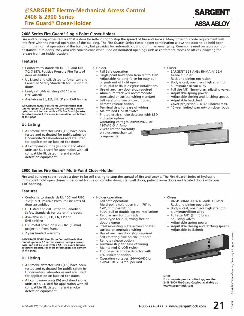
e SARGENT Electro-Mechanical Access Control2408 & 2900 Series Fire Guard® Closer-Holder
2408 Series Fire Guard® Single Point Closer-HolderFire and building codes require that a door be self-closing to stop the spread of fire and smoke. Many times this code requirement willinterfere with the normal operation of the building. The Fire Guard® Series closer-holder combination allows the door to be held openduring the normal operation of the building, but provides for automatic closing during an emergency. Commonly used on cross corridoror stairwell fire doors, they also add convenience when used on nonrated openings such as conference rooms or offices, allowing for release from an inside location.
• Conforms to standards UL 10C and UBC 7-2 (1997), Positive Pressure Fire Tests of door assemblies
• UL Listed and cUL Listed to American andCanadian Safety Standards for use on firedoors
• Easily retrofits existing 2407 Series Fire Guards
• Available in EB, ED, EN, EP and EAB finishes
• Holder– Fail Safe operation– Single point hold open from 85° to 110°– Adjustable holding force for easy pull
or push out of hold open– Push, pull or double egress installations– Use of auxiliary door stop required– Aluminum track will accommodate
concealed or surface wiring standard– Self resetting fuse on circuit board– Remote release option– Terminal strip for ease of wiring– Maintained On/Off switch– Photoelectric smoke detector with LED
indicator option– Operating voltages: 24VAC/VDC, or
120VAC @ .1 Amp.– 2 year limited warranty
on electromechanical components
• Closer– SARGENT 351 ANSI/ BHMA A156.4
Grade 1 Closer– Rack and pinion operation– Body is cast, one piece high strength
aluminum / silicon alloy– Full size 1/8" (3mm) brass adjusting valves– Adjustable spring power– Adjustable closing and latching speeds– Adjustable backcheck– Cover projection 2-3/16" (56mm) max.– 10 year limited warranty on closer body
Features
UL Listing
• All smoke detector units (12-) have been tested and evaluated for public safety by Underwriter’s Laboratories and are listed for application on labeled fire doors
• All companion units (9-) and stand alone units are UL Listed for application with allcompatible UL Listed fire and smoke detection equipment
IMPORTANT NOTE: Fire Alarm Control Panels that cannot ignore a 0.5 second closure during a powercycle, can not be used with a 12- Fire Guard (smokedetector) product. For more information, see bottomof this page
IMPORTANT NOTE: Fire Alarm Control Panels that cannot ignore a 0.5 second closure during a powercycle, can not be used with a 12- Fire Guard (smokedetector) product. For more information, see bottomof this page.
2900 Series Fire Guard® Multi-Point Closer-HolderFire and building codes require a door to be self-closing to stop the spread of fire and smoke. The Fire Guard® Series of hydraulic multi-point hold open closers is designed for use on corridor doors, stairwell doors, patient room doors and labeled doors with over 110˚ opening.
Features
• All smoke detector units (12-) have been tested and evaluated for public safety by Underwriters Laboratories and are listed for application on labeled fire doors
• All companion units (9-) and stand alone units are UL Listed for application with allcompatible UL Listed fire and smokedetection equipment
UL Listing
• Conforms to standards UL 10C and UBC 7-2 (1997), Positive Pressure Fire Tests of door assemblies
• UL Listed and cUL Listed to Canadian Safety Standards for use on fire doors
• Available in EB, ED, EN, EP and EAB finishes
• Full metal cover, only 2-9/16" (65mm) projection from frame
• 2 year limited warranty
• Holder operation– Fail Safe operation– Multi-point hold open from 70° to
170°, trim permitting– Push, pull or double egress installations– Regular arm for push side– Track type for pull, swing free or
double egress– Steel mounting plate accommodates
surface or concealed wiring– Use of auxiliary door stop required– Self resetting fuse on circuit board– Remote release option– Terminal strip for ease of wiring– Maintained On/Off switch– Photoelectric smoke detector with
LED indicator option – Operating voltages: 24VAC/VDC or
120VAC @ .25 Amp. per unit
• Closer– ANSI/ BHMA A156.4 Grade 1 Closer– Rack and pinion operation– Body is cast, one piece high strength
aluminum/silicon alloy– Full size 1/8" (3mm) brass
adjusting valves– Adjustable spring power– Adjustable closing and latching speeds– Adjustable backcheck
NOTE: For complete product offerings, see the 2408/2900 FireGuard Catalog available atwww.sargentlock.com
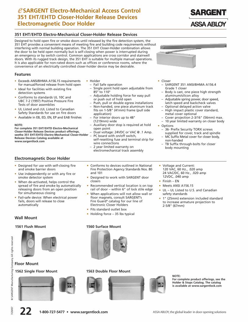
227/20
/07
© S
AR
GEN
T M
anu
fact
uri
ng
Co
mp
any
All
rig
hts
res
erve
d
1-800-727-5477 • www.sargentlock.com
• Designed for use with self-closing fire and smoke barrier doors
• Use independently or with any fire or smoke detector system
• When de-activated, helps control the spread of fire and smoke by automaticallyreleasing doors from an open position for simultaneous closing
• Fail-safe device: When electrical power fails, doors will release to close automatically
• Conforms to devices outlined in National Fire Protection Agency Standards Nos. 80 and 101
• Designed to work with SARGENT doorclosers
• Recommended vertical location is on top rail of door – within 6" of lock stile edge
• When applications will not allow wall orfloor magnets, consult SARGENT’s Fire Guard® catalog for our line ofElectronic Closer Holders
• Fits standard outlet box• Holding force – 35 lbs typical
• Voltage and Current:120 VAC, 60 Hz., .020 amp24 VAC/DC, 60 Hz., .020 amp12VDC, .040 amp
• Finish – EN• Meets ANSI A156.15• UL – UL Listed to U.S. and Canadian
safety standards• 1" (25mm) extension included standard
to increase armature projection to 2-5/8" (67mm)
Electromagnetic Door Holder
1561 Flush Mount 1560 Surface Mount
1562 Single Floor Mount 1563 Double Floor Mount
Floor Mount
Wall Mount
e SARGENT Electro-Mechanical Access Control351 EHT/EHTD Closer-Holder Release DevicesElectromagnetic Door Holder
351 EHT/EHTD Electro-Mechanical Closer-Holder Release DevicesDesigned to hold open fire or smoke doors until released by the fire detection system, the 351 EHT provides a convenient means of meeting fire and building code requirements without interfering with normal building operation. The 351 EHT Closer-Holder combination allows the door to be held open normally but is self-closing when power is interrupted during an emergency or by switch control. Common applications are cross corridor and stairwell doors. With its rugged track design, the 351 EHT is suitable for multiple manual operations.It is also applicable for non-rated doors such as offices or conference rooms, where the convenience of an electrically controlled closer-holder device may be desirable.
• Exceeds ANSI/BHMA A156.15 requirementsfor manual/forced release from hold open
• Ideal for facilities with existing fire detection systems
• Conforms to standards UL 10C and UBC 7-2 (1997) Positive Pressure Fire Tests of door assemblies
• UL Listed and cUL Listed to Canadian Safety Standards for use on fire doors
• Available in EB, ED, EN, EP and EAB finishes
• Holder– Fail Safe operation– Single point hold open adjustable from
85° to 110°– Adjustable holding force for easy pull
or push out of hold open– Push, pull or double egress installations– Non-handed, one piece aluminum track
fits on 1-5/8" (41mm) frame (pull side application)
– For interior doors up to 48" (1219mm) wide
– Auxiliary door stop is required at hold open point
– Dual voltage: 24VDC or VAC @ .1 Amp.– PC board with on/off switch,
self-resetting fuse and terminal strip for wire connections
– 2 year limited warranty on electromechanical track assembly
• Closer– SARGENT 351 ANSI/BHMA A156.4
Grade 1 closer– Body is cast, one piece high strength
aluminum/silicon alloy– Adjustable spring power, door speed,
latch speed and backcheck valves– Optional delayed action valve– High impact plastic cover standard,
metal cover optional– Cover projection 2-3/16" (56mm) max.– 10 year limited warranty on closer body
• Options– 36- Prefix Security TORX screws
supplied for cover, track and spindle– MC Suffix Metal cover for closer body,
non-handed– TB Suffix through-bolts for closer
body mounting
Features
NOTE: For complete 351 EHT/EHTD Electro-MechanicalCloser-Holder Release Devices product offerings, seethe 351 EHT/EHTD Electro-Mechanical Closer-HolderRelease Devices Catalog available at www.sargentlock.com
NOTE: For complete product offerings, see theHolder & Stops Catalog. The catalogis available at www.sargentlock.com
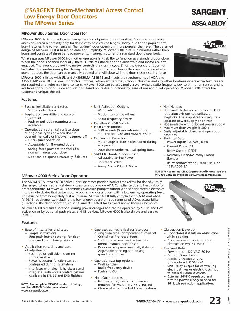
23 7/20
/07
© S
AR
GEN
T M
anu
fact
uri
ng
Co
mp
any
All
rig
hts
res
erve
d
1-800-727-5477 • www.sargentlock.com
e SARGENT Electro-Mechanical Access ControlLow Energy Door OperatorsThe MPower Series
MPower 4000 Series Door OperatorThe SARGENT MPower 4000 Series Door Operators provide barrier free access for the physicallychallenged when mechanical door closers cannot provide ADA Compliance due to heavy door ordraft conditions. MPower 4000 combines hydraulic pump/manifold with sophisticated electronicsinto a single device that automatically opens and closes doors with a low energy operating force.Constructed from heavy-duty cast aluminum, MPower 4000 fully complies with ADA and ANSIA156.19 requirements, including the low energy operator requirements of ADA’s accessibilityguidelines. The door operator is also UL and cUL listed for fire and smoke barrier assemblies.
MPower 4000 remains functional during power outages and can be operated by “Push and Go” activation or by optional push plates and RF devices. MPower 4000 is also simple and easy toinstall.
• Ease of installation and setup– Simple instructions– Uses push-button settings for door
open and door close positions
• Application versatility and ease of adjustment– Push side or pull side mounting
units available– Power Operator function can be
configured during installation– Interfaces with electric hardware and
integrates with access control systems– Available in EN, EB and EAB finishes
• Operates as mechanical surface closer during close cycles or if power is turned off– Critical for fire rated doors– Spring force provides the feel of a
normal manual door closer– Door can be opened manually if desired– Adjustable opening and closing
speeds and forces
• Operation startup options– Wall switches– Radio frequency device– Push and Go
• Hold Open options– 0-30 seconds (5 seconds minimum
required for ADA and ANSI A156.19)– Choice of indefinite hold open features
• Obstruction Detection– Door closes if it hits an obstruction
while opening– Door re-opens once if it hits an
obstruction while closing• Electrical Data
– Power Input: 120 VAC, 60 Hz – Current Draw 2 amp– Auxiliary Output 24VDC
(unregulated) @ 500 mA– SPDT relay output for controlling
electric strikes or electric locks not to exceed 5 amp @ 24VDC
– External 24VDC regulated and filtered power supply needed for 56- latch retraction applications
Features
MPower 3000 Series Door OperatorMPower 3000 Series introduces a new generation of power door operators. Door operators were once considered a necessity only for those with physical challenges. Today, due to the population’sbusy lifestyles, the convenience of “hands-free” door opening is more popular than ever. The patenteddesign of MPower 3000 is based on ease and simplicity. MPower 3000 installs in minutes rather thanhours and consists of three basic components: inverter, motor and a standard door closer body.
What separates MPower 3000 from other operators is its ability to function as a standard door closer.When the door is opened manually, there is little resistance and the drive train and motor are notengaged. The door closer, not the motor, controls the closing cycle. Since the door closer does notback-drive the motor during the closing cycle, there is no loss of closer efficiency. In the event of apower outage, the door can be manually opened and will close with the door closer’s spring force.
MPower 3000 is listed with UL and ANSI/BHMA A156.19 and meets the requirements of ADA andA156.4. MPower 3000 is ideal for doctors’ offices, retirement facilities, schools, churches and any other locations where extra features arenot required and noise may be a concern. MPower 3000 can be activated via wall switch, radio frequency device or motion sensor, and isavailable for push or pull side applications. Based on its dual functionality, ease of use and quiet operation, MPower 3000 offers the customer a unique choice!
• Ease of installation and setup– Simple instructions
• Application versatility and ease of adjustment– Push or pull side mounting units
available• Operates as mechanical surface closer
during close cycles or when door isopened manually or if power is turned off– Ultra-Quiet operation– Acceptable for fire-rated doors– Spring force provides the feel of a
normal manual door closer– Door can be opened manually if desired
• Unit Activation Options– Wall switches– Motion sensor (by others)– Radio frequency device
• End-User On/Off Switch• Hold Open options
– 0-30 seconds (5 seconds minimumrequired for ADA and ANSI A156.19)
• Obstruction Detection– Motor stops if door is obstructed during
an opening– Door closes under manual spring force
• SARGENT Grade 1 door closer– Adjustable Spring Power– Backcheck Valve– Sweep Valve & Latch Valve
• Non-Handed• Not available for use with electric latch
retraction exit devices, strikes, ormaglocks. These applications require aseparate power supply and timer
• Not available with onboard power supply• Maximum door weight is 200lb• Easily adjustable closed and open door
positions• Electrical Data
– Power Input; 120 VAC, 60Hz– Current Draw; .6A– Relay Output; DPDT– Normally Open/Normally Closed
(jumper)– Relay contact ratings; 30VDC@1A or
Features
NOTE: For complete MP3000 product offerings, see the MP3000 Catalog available at www.sargentlock.com
NOTE: For complete MP4000 product offerings, see the MP4000 Catalog available at www.sargentlock.com
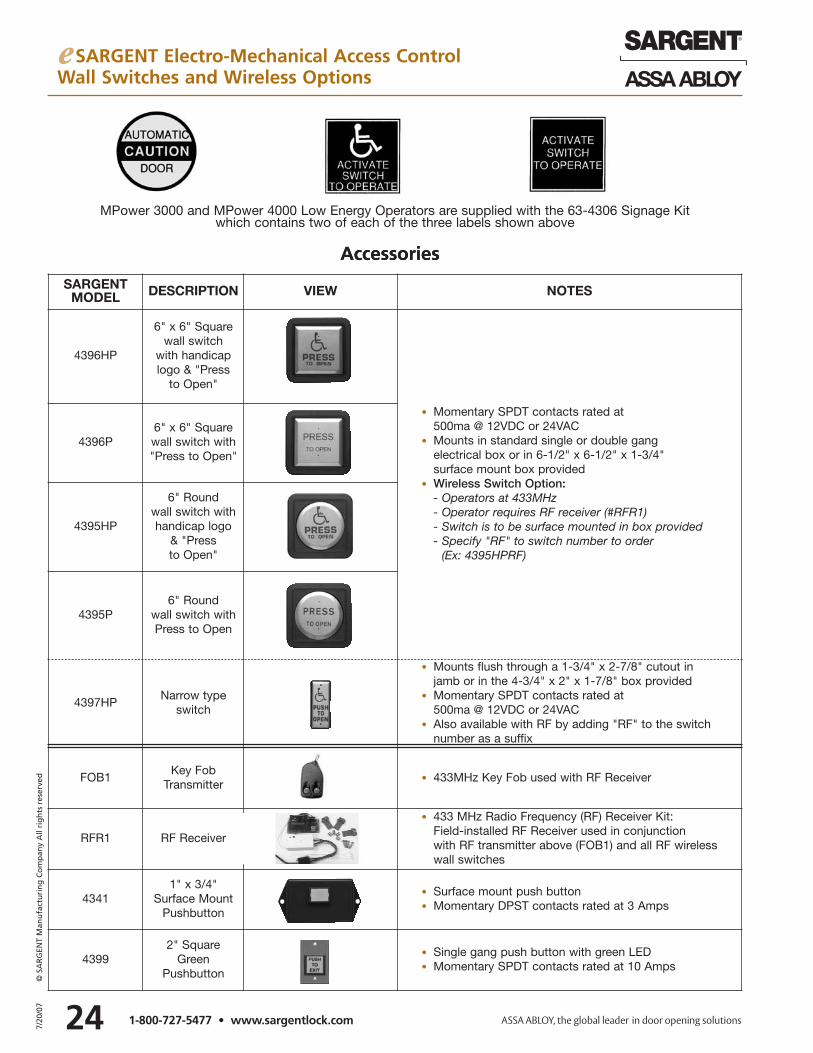
e SARGENT Electro-Mechanical Access ControlWall Switches and Wireless Options
247/20
/07
© S
AR
GEN
T M
anu
fact
uri
ng
Co
mp
any
All
rig
hts
res
erve
d
1-800-727-5477 • www.sargentlock.com
Accessories
MPower 3000 and MPower 4000 Low Energy Operators are supplied with the 63-4306 Signage Kit which contains two of each of the three labels shown above
SARGENTMODEL DESCRIPTION VIEW NOTES
4396HP
6" x 6" Squarewall switch
with handicap logo & "Press
to Open"
• Momentary SPDT contacts rated at 500ma @ 12VDC or 24VAC
• Mounts in standard single or double gang electrical box or in 6-1/2" x 6-1/2" x 1-3/4" surface mount box provided
• Wireless Switch Option:- Operators at 433MHz - Operator requires RF receiver (#RFR1)- Switch is to be surface mounted in box provided- Specify "RF" to switch number to order
(Ex: 4395HPRF)
4396P6" x 6" Squarewall switch with "Press to Open"
4395HP
6" Round wall switch withhandicap logo
& "Press to Open"
4395P6" Round
wall switch withPress to Open
4397HPNarrow type
switch
• Mounts flush through a 1-3/4" x 2-7/8" cutout injamb or in the 4-3/4" x 2" x 1-7/8" box provided
• Momentary SPDT contacts rated at500ma @ 12VDC or 24VAC
• Also available with RF by adding "RF" to the switchnumber as a suffix
FOB1Key Fob
Transmitter• 433MHz Key Fob used with RF Receiver
RFR1 RF Receiver
• 433 MHz Radio Frequency (RF) Receiver Kit: Field-installed RF Receiver used in conjunction with RF transmitter above (FOB1) and all RF wireless wall switches
43411" x 3/4"
Surface MountPushbutton
• Surface mount push button• Momentary DPST contacts rated at 3 Amps
43992" Square
Green Pushbutton
• Single gang push button with green LED • Momentary SPDT contacts rated at 10 Amps
Accessories
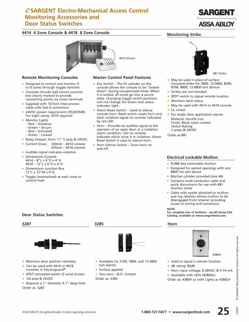
e SARGENT Electro-Mechanical Access ControlMonitoring Accessories andDoor Status Switches
25 7/20
/07
© S
AR
GEN
T M
anu
fact
uri
ng
Co
mp
any
All
rig
hts
res
erve
d
1-800-727-5477 • www.sargentlock.com
Remote Monitoring Consoles• Designed to control and monitor 4
or 8 zones through toggle switches• Consoles include wall mount junction
box clearly marked to provide connecting points via screw terminals
• Supplied with 10 foot interconnectcable with Sub D connectors
• 24VDC power requirement (3520/3540)For eight zones, 3570 required
• Monitor Lights– Red – Violation– Green – Secure– Red – Unlocked– Green – Locked
• Relay Output: Form “C” 5 amp @ 24VDC• Current Draw: 320mA – 4414 console
635mA – 4418 console• Audible signal indicates violation• Dimensions–Console
4414 – 8"L x 6"D x 4"H4418 – 12"L x 6"D x 4"H
• Dimensions–Junction Box12"L x 12"W x 4"D
• Toggle (maintained) at each zone tocontrol load
Monitoring Strike
Horn
Electrical Lockable Mullion• EL980 Key-removable mullion• Designed for paired openings with any
8800 rim exit device• Mortise cylinder provided (size 46)• Contains multi-conductor cable and
quick disconnects for use with 881 monitor strike
• Cable with eyelet attached to mullion and top retainer allows mullion to be disengaged from retainer providing access to wiring and connectors
Door Status Switches
Master Control Panel Features• Key Switch – The 41 cylinder on the
console allows the console to be “lockeddown” during unsupervised times. Whenit is locked, all zones go into a securestate. Changing toggle switch positionswill not change the Green lock status indicator light.
• Alarm Reset Switch – Used to silence console horn. Reset switch resets horn andlatch violation signal on console indicatedby red LED.
• Horn – Provides an audible signal to theoperator of an open door or a violationalarm condition. LED on console indicates which zone is in violation. AlarmReset Switch is used to silence horn.
• Horn Silence Switch – Turns horn on and off
3287 3285
4414 4 Zone Console & 4418 8 Zone Console
• May be used in place of surface mounted strike for 5800, 12-5800, 8500, 8700, 8800, 12-8800 exit devices
• Strikes are non-handed• SPDT switch to signal remote location• Monitors latch status• May be used with 4414 or 4418 console• UL Listed• For single door application alarms
Material: Ductile IronFinish: Black nylon coatedSwitch Rating:2 amps @ 24VDC
Order as 881
• Used to signal a remote location• dB rating: 85dB• Horn input voltage: 6-28VDC @ 3-14 mA• Available with LEDs (4380HL)Order as: 4380H or with Lights as 4380LH
• Available for 5100, 5800, and 12-5800 exit alarms
• Surface applied• Two wire – N.O. ContactOrder as: 3285
• Monitors door position remotely• Can be used with 4414 or 4418
consoles or Electroguard®
• SPDT concealed switch (3 wire)–brown• 1/4 amp @ 24VDC• Requires a 1" diameter X 1" deep holeOrder as: 3287
4414 Shown
4380H
881 Strike
NOTE: For complete line of mullions - see 80 Series ExitCatalog, available at www.sargentlock.com.
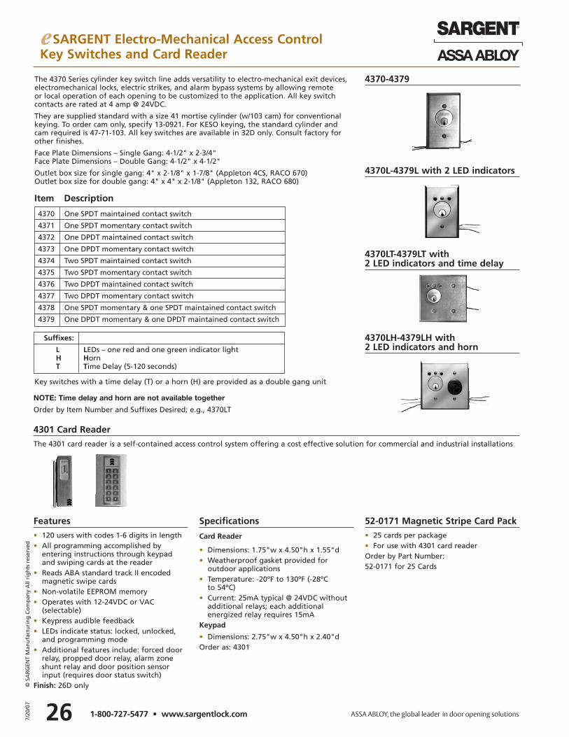
e SARGENT Electro-Mechanical Access ControlKey Switches and Card Reader
267/20
/07
© S
AR
GEN
T M
anu
fact
uri
ng
Co
mp
any
All
rig
hts
res
erve
d
1-800-727-5477 • www.sargentlock.com
The 4370 Series cylinder key switch line adds versatility to electro-mechanical exit devices, electromechanical locks, electric strikes, and alarm bypass systems by allowing remote or local operation of each opening to be customized to the application. All key switch contacts are rated at 4 amp @ 24VDC.
They are supplied standard with a size 41 mortise cylinder (w/103 cam) for conventionalkeying. To order cam only, specify 13-0921. For KESO keying, the standard cylinder andcam required is 47-71-103. All key switches are available in 32D only. Consult factory forother finishes.
Face Plate Dimensions – Single Gang: 4-1/2" x 2-3/4"Face Plate Dimensions – Double Gang: 4-1/2" x 4-1/2"
Outlet box size for single gang: 4" x 2-1/8" x 1-7/8" (Appleton 4CS, RACO 670)Outlet box size for double gang: 4" x 4" x 2-1/8" (Appleton 132, RACO 680)
Key switches with a time delay (T) or a horn (H) are provided as a double gang unit
4370-4379
4370L-4379L with 2 LED indicators
4370LT-4379LT with 2 LED indicators and time delay
4370LH-4379LH with 2 LED indicators and horn
Suffixes:
L LEDs – one red and one green indicator lightH HornT Time Delay (5-120 seconds)
4370 One SPDT maintained contact switch
4371 One SPDT momentary contact switch
4372 One DPDT maintained contact switch
4373 One DPDT momentary contact switch
4374 Two SPDT maintained contact switch
4375 Two SPDT momentary contact switch
4376 Two DPDT maintained contact switch
4377 Two DPDT momentary contact switch
4378 One SPDT momentary & one SPDT maintained contact switch
4379 One DPDT momentary & one DPDT maintained contact switch
Item Description
Features• 120 users with codes 1-6 digits in length• All programming accomplished by
entering instructions through keypad and swiping cards at the reader
• Reads ABA standard track II encoded magnetic swipe cards
• Non-volatile EEPROM memory• Operates with 12-24VDC or VAC
(selectable) • Keypress audible feedback• LEDs indicate status: locked, unlocked,
and programming mode• Additional features include: forced door
relay, propped door relay, alarm zone shunt relay and door position sensor input (requires door status switch)
Finish: 26D only
Specifications
Card Reader
• Dimensions: 1.75"w x 4.50"h x 1.55"d• Weatherproof gasket provided for
outdoor applications• Temperature: -20ºF to 130ºF (-28ºC
to 54ºC)• Current: 25mA typical @ 24VDC without
additional relays; each additional energized relay requires 15mA
Keypad
• Dimensions: 2.75"w x 4.50"h x 2.40"dOrder as: 4301
52-0171 Magnetic Stripe Card Pack• 25 cards per package• For use with 4301 card readerOrder by Part Number:52-0171 for 25 Cards
4301 Card ReaderThe 4301 card reader is a self-contained access control system offering a cost effective solution for commercial and industrial installations
NOTE: Time delay and horn are not available together
Order by Item Number and Suffixes Desired; e.g., 4370LT
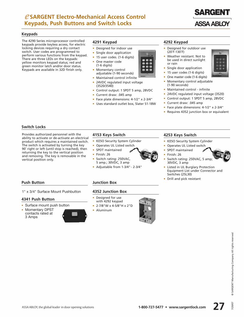
e SARGENT Electro-Mechanical Access ControlKeypads, Push Buttons and Switch Locks
27 7/20
/07
© S
AR
GEN
T M
anu
fact
uri
ng
Co
mp
any
All
rig
hts
res
erve
d
1-800-727-5477 • www.sargentlock.com
Keypads
The 4290 Series microprocessor controlledkeypads provide keyless access, for electriclocking devices requiring a dry contactswitch. User codes are programmed to perform various functions from the keypad.There are three LEDs on the keypads: yellow monitors keypad status; red andgreen monitor latch and/or door status.Keypads are available in 32D finish only.
Push Button
4341 Push Button• Surface mount push button• Momentary DPST
contacts rated at 3 Amps
1" x 3/4" Surface Mount Pushbutton
Provides authorized personnel with the ability to activate or de-activate an electricalproduct which requires a maintained switch.The switch is activated by turning the key90˚ right or left (until stop is reached), thenreturning the key to the vertical positionand removing. The key is removable in thevertical position only.
4291 Keypad• Designed for indoor use• Single door application• 15 user codes. (1-6 digits)• One master code
(1-6 digits)• Momentary control
adjustable (1-90 seconds)• Maintained control infinite• 24VDC regulated input voltage
(3520/3540)• Control output: 1 SPDT 5 amp, 28VDC• Current draw: .045 amp• Face plate dimensions: 4-1/2" x 2-3/4"• Uses standard outlet box, Slater S1-18W
4292 Keypad• Designed for outdoor use
(20˚F-130˚F)• Weather resistant. Not to
be used in direct sunlight or rain
• Single door application• 15 user codes (1-6 digits)• One master code (1-6 digits)• Momentary control adjustable
(1-90 seconds)• Maintained control - infinite• 24VDC regulated input voltage (3520)• Control output: 1 SPDT 5 amp, 28VDC• Current draw: .045 amp• Face plate dimensions: 4-1/2" x 2-3/4"• Requires 4352 junction box or equivalent
Switch Locks
4253 Keys Switch• KESO Security System Cylinder• Operates UL Listed switch• SPDT maintained• Finish: 26• Switch rating: 250VAC, 5 amp;
30VDC, 3 amp• Listed in UL Burglary Protection
Equipment List under Connector and Switches (25L30)
• Drill and pick resistant
4153 Keys Switch• KESO Security System Cylinder• Operates UL Listed switch• SPDT maintained• Finish: 26• Switch rating: 250VAC,
5 amp.; 30VDC, 3 amp• Adjustable from 1-3/4" - 2-3/4"
Junction Box
4352 Junction Box• Designed for use
with 4292 keypad• 2-7/8"W x 4-5/8"H x 2"D• Aluminum
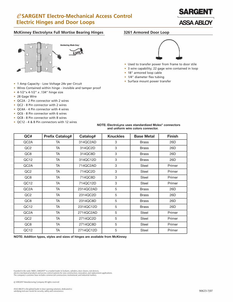
e SARGENT Electro-Mechanical Access ControlElectric Hinges and Door Loops
3261 Armored Door Loop
• Used to transfer power from frame to door stile• 3 wire capability; 22 gage wire contained in loop• 18" armored loop cable• 1/4" diameter flex tubing • Surface mount power transfer
McKinney Electrolynx Full Mortise Bearing Hinges
• 1 Amp Capacity - Low Voltage 24v per Circuit• Wires Contained within hinge - invisible and tamper proof• 4-1/2"x 4-1/2" x .134" hinge size• 28 Gage Wire• QC2A - 2 Pin connector with 2 wires• QC2 - 8 Pin connector with 2 wires• QC4A - 4 Pin connector with 4 wires• QC6 - 8 Pin connector with 6 wires• QC8 - 8 Pin connector with 8 wires• QC12 - 4 & 8 Pin connectors with 12 wires
QC# Prefix Catalog# Catalog# Knuckles Base Metal Finish
QC2A TA 314QC2AD 3 Brass 26D
QC2 TA 314QC2D 3 Brass 26D
QC8 TA 314QC8D 3 Brass 26D
QC12 TA 314QC12D 3 Brass 26D
QC2A TA 714QC2AD 3 Steel Primer
QC2 TA 714QC2D 3 Steel Primer
QC8 TA 714QC8D 3 Steel Primer
QC12 TA 714QC12D 3 Steel Primer
QC2A TA 2314QC2AD 5 Brass 26D
QC2 TA 2314QC2D 5 Brass 26D
QC8 TA 2314QC8D 5 Brass 26D
QC12 TA 2314QC12D 5 Brass 26D
QC2A TA 2714QC2AD 5 Steel Primer
QC2 TA 2714QC2D 5 Steel Primer
QC8 TA 2714QC8D 5 Steel Primer
QC12 TA 2714QC12D 5 Steel Primer
NOTE: Addition types, styles and sizes of hinges are available from McKinney
NOTE: ElectroLynx uses standardized Molex® connectorsand uniform wire colors connector.
Founded in the early 1800’s, SARGENT® is a market leader in locksets, cylinders, door closers, exit devices, electro-mechanical products and access control systems for new construction, renovation, and replacement applications. The company’s customer base includes commercial construction, institutional, and industrial markets.
© SARGENT Manufacturing Company All rights reserved
ASSA ABLOY is the global leader in door opening solutions, dedicated to satisfying end-user needs for security, safety and convenience. 90623-7/07