Image Compression: JPEG Multimedia Systems (Module 4 Lesson 1)
EE678 WAVELETS APPLICATION ASSIGNMENT 1
SAR Image compression Using JPEG-2000
Group Members: G.Kannan [email protected] 04407604 S.Nandakumar [email protected] 04307416 E.Ramanji Reddy [email protected] 04307036
Abstract
In this project we analyze the application of JPEG-2000 image compression on synthetic aperture radar system. We compare the JPEG-2000 with JPEG interms of various performance criteria, and give the method of implementing SAR in FPGA based hardware. We also illustrate the JPEG-2000 image compression with typical SAR image.
Index Terms SAR, JPEG-2000, DWT and DCT
I. INTRODUCTION
Uncompressed multimedia (graphics, audio and video) data requires considerable storage capacity and transmission bandwidth. Despite rapid progress in mass-storage density, processor speeds, and digital communication system performance, demand for data storage capacity and data-transmission bandwidth continues to outstrip the capabilities of available technologies. The recent growth of data intensive multimedia-based web applications have not only sustained the need for more efficient ways to encode signals and images but have made compression of such signals central to storage and communication technology.
In the case of synthetic aperture radar (SAR), radar platform will be on aircraft (or on satellite). Radar system at such elevated platform has to have lesser amount of storage space and processing hardware to reduce the cost and space. More over the bandwidth limitation on the downlink (from aircraft/ satellite to ground station) place the major constraint on the amount of data. The image compression techniques plays major role in such a scenario.
For still image compression, the Joint Photographic Experts Group (JPEG) standard has been established by ISO (International Standards Organization) and IEC International Electro-Technical Commission). The performance of these coders generally degrades at low bit-rates mainly because of the underlying block-based Discrete Cosine Transform (DCT) scheme. More recently, the wavelet transform has emerged as a cutting edge technology, within the field of image compression. Wavelet-based coding provides
EE678 Wavelets Application Assignment, April 2005
EE678 WAVELETS APPLICATION ASSIGNMENT 2
substantial improvements in picture quality at higher compression ratios. Over the past few years, a variety of powerful and sophisticated wavelet-based schemes for image compression, as discussed later, have been developed and implemented. Because of the many advantages, the top contenders in the upcoming JPEG-2000 standard are all wavelet-based compression algorithms.
This whole report is arranged in the following flow. First, for readers new to SAR and image compression, we briefly review some basic concepts on SAR and image compression and present a short overview of the DCT-based JPEG. In section 2 we compare the DCT and wavelet based image coding schemes and, for more advanced readers, in section 3 we mention a few sophisticated, modern, and popular wavelet-based coding techniques. The goal of the upcoming JPEG-2000 image compression standard, which is going to be wavelet-based, is briefly presented. For those who are interested in implementation aspects we have provided a separate session for hardware implementation of JPEG-2000.
II. BACKGROUND THEORY 1. Synthetic aperture Radar
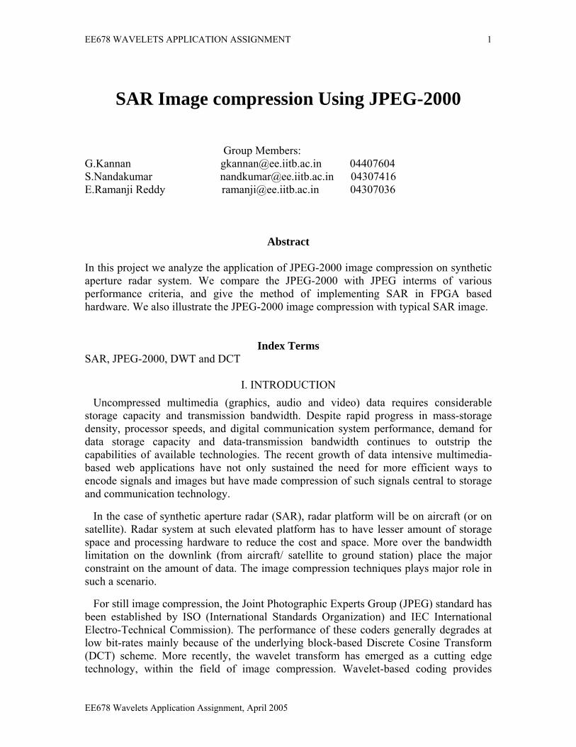
Fig 1. Synthetic aperture Radar. Synthetic aperture radar (SAR) systems, which are typically mounted on aircraft and satellites, transmit and receive microwaves as shown in Fig 1. SAR antennas are a type of radar antenna designed to take advantage of their satellite's (aircraft) movement, thus creating a "synthetic" aperture or opening [1].
SAR images, which resemble photographs, are actually maps in which the brightness shown is a measure of the radar energy reflected back to the antenna. Water droplets in fog and clouds are transparent to radio waves of the proper frequency just as window glass is to light waves of the visible frequency. Hence, a SAR instrument can gather data
EE678 Wavelets Application Assignment, April 2005
EE678 WAVELETS APPLICATION ASSIGNMENT 3
in conditions where optical sensors would be useless, i.e. it can provide excellent images of what the radar detected even in fog, clouds or darkness. SAR data is used to study agriculture, ecology, geology, oceanography, and hydrology as well as shipping in ice-covered seas, oil exploration, ocean pollution monitoring, and ocean research.
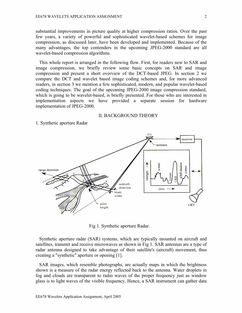
The transmitted microwaves travel to the earth and scatter when they bounce off of objects and the ground. Different objects and different types of terrain scatter microwaves differently. The amount of scattering determines the grey-levels (tones) of objects in the SAR image. For example, water produces a relatively dark tone since it produces little backscatter towards the radar, trees give medium tones, and buildings correspond to light tones as shown in Fig 1. By analyzing the backscattering, it is possible to characterize surface properties of the earth, such as chemical composition, vegetation, and ambient temperatures. The resolution of these features is dependent on the spatial sampling in the SAR image. The target resolution area (called the resolution cell) must be sampled by at least 2 x 2 pixels. An typical SAR image is shown in Fig 2.
Fig 2. This is a radar image taken by the Shuttle Imaging Radar
A SAR image can be modeled as a sum of four components. The micro-texture, which is the speckle noise, appears as randomly placed bright spots the same size or a little larger than the resolution cell [2]. The meso-texture, also called the scene texture, is the variation of backscatter due to the material and geometry of the objects. This grainy texture has an elementary unit covering several resolution cells and is very important for image interpretation. The macro-texture refers to variations in radar brightness that are larger than many resolution cells. It arises from objects such as roads, geological lineaments, field boundaries, and forest shadows. Homogeneous regions are characterized by the mean backscattering of homogeneous areas. Speckle noise is formed during the processing of the radar returns into a SAR image. Speckle noise masks fine details in the SAR image. In some applications, it is desirable to reduce the inherent speckle noise. There are essentially two categories of speckle reduction techniques: multi-looking, which is performed on raw data, and filtering, which
EE678 Wavelets Application Assignment, April 2005
EE678 WAVELETS APPLICATION ASSIGNMENT 4
is performed on image data. In multi-looking, we average neighboring pixels incoherently to remove speckle. The number of pixels averaged is called the number of looks N. If we average Na, pixels in azimuth direction and Nr, pixels in range direction, then the total number of looks becomes N = NaNr. As an alternative, filtering can be used, which acts as a first step in segmentation of an image for later classification. Speckle can be removed using filtering techniques such as mean filtering, median filtering, highpass filtering, edge preserving smoothing filtering, local statistics filtering, or sigma filtering.
2. The Formation of SAR Images
The received signal echo from the ground is sampled and converted into a digital image. Note that the pixel spacing in the final image and the resolution of the system may not be the same. If a system with a resolution of 5m is set to oversample the signal and produces an image in which each pixel corresponds to 3m, we do not get a more detailed image the information is just smeared out over several pixels. In this case, the image is correlated and is much more difficult to process [2]. The field recorded at pixel , denoted E(x), can be written
),())(exp()()( xshsisaxEs
φ∑=
where the summation ranges over the scatterers, a(s) and )(sφ are the amplitude and phase of the signal received from the scatter s, and h is the instrument function The value of h is near 1 when s is in or near the resolving cell corresponding to pixel , and near zero otherwise. If we assume that h is translation-invariant (does not depend on ) then it can be written as a one-parameter function: h(s,x). Thus the detected field E is an array of complex numbers. The square of the modulus of the field at is called the detected intensity at ; the square-root of the intensity is called the envelope or the amplitude. Note that this is not the same as the amplitude of the received signal because the received field is perturbed by the instrument function. The amplitude of the received signal, a(s) is called the reflectivity, and its square is called the surface cross-section. It is this that we try to recreate when reducing the speckle. Datasets for SAR images can be stored as either intensity or amplitude data. It is important that you know what type of data you are using. Many images are stored as amplitude since the speckle is less obtrusive when these images are displayed. Modern spaceborne synthetic aperture radar (SAR) systems have onboard hardware that consists of transmitting and receiving units, an analog-to-digital converter, realtime data downlink, and a storage facility. One of the primary constraints in the design and operation of spaceborne SAR systems is the unavailability of a downlink with a high enough data rate. The data rate of each channel is proportional to the pulse repetition frequency, the number of sampled values in each received echo, and the number of quantization bits in each sample. Reducing the data rate deteriorates the system performance. Therefore, data compression offers a practical solution. Data compression algorithms can be classified as lossless and lossy. Lossless compression algorithms such as Huffman coding, arithmetic coding, run-length encoding, and Lempel-Ziv coding [2] are used when exact reconstruction of the original data set is necessary. Lossy
EE678 Wavelets Application Assignment, April 2005
EE678 WAVELETS APPLICATION ASSIGNMENT 5
compression algorithms such as predictive coding, transform/subband coding, vector quantization, and fractal coding are used for applications in which some degree of degradation of the data is tolerable and/or high compression ratio is preferred.
III. APPLICATION
1. Image Compression
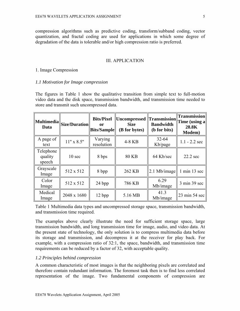
1.1 Motivation for Image compression The figures in Table 1 show the qualitative transition from simple text to full-motion video data and the disk space, transmission bandwidth, and transmission time needed to store and transmit such uncompressed data.
Multimedia Data Size/Duration
Bits/Pixel or
Bits/Sample
Uncompressed Size
(B for bytes)
Transmission Bandwidth (b for bits)
TransmissionTime (using a
28.8K Modem)
A page of text 11'' x 8.5'' Varying
resolution 4-8 KB 32-64 Kb/page 1.1 - 2.2 sec
Telephone quality speech
10 sec 8 bps 80 KB 64 Kb/sec 22.2 sec
Grayscale Image 512 x 512 8 bpp 262 KB 2.1 Mb/image 1 min 13 sec
Color Image 512 x 512 24 bpp 786 KB 6.29
Mb/image 3 min 39 sec
Medical Image 2048 x 1680 12 bpp 5.16 MB 41.3
Mb/image 23 min 54 sec
Table 1 Multimedia data types and uncompressed storage space, transmission bandwidth, and transmission time required.
The examples above clearly illustrate the need for sufficient storage space, large transmission bandwidth, and long transmission time for image, audio, and video data. At the present state of technology, the only solution is to compress multimedia data before its storage and transmission, and decompress it at the receiver for play back. For example, with a compression ratio of 32:1, the space, bandwidth, and transmission time requirements can be reduced by a factor of 32, with acceptable quality.
1.2 Principles behind compression A common characteristic of most images is that the neighboring pixels are correlated and therefore contain redundant information. The foremost task then is to find less correlated representation of the image. Two fundamental components of compression are
EE678 Wavelets Application Assignment, April 2005
EE678 WAVELETS APPLICATION ASSIGNMENT 6
redundancy and irrelevancy reduction. Redundancy reduction aims at removing duplication from the signal source (image/video). Irrelevancy reduction omits parts of the signal that will not be noticed by the signal receiver, namely the Human Visual System (HVS). In general, three types of redundancy can be identified:
• Spatial Redundancy or correlation between neighboring pixel values.
• Spectral Redundancy or correlation between different color planes or spectral bands.
• Temporal Redundancy or correlation between adjacent frames in a sequence of images (in video applications).
Image compression research aims at reducing the number of bits needed to represent an image by removing the spatial and spectral redundancies as much as possible.
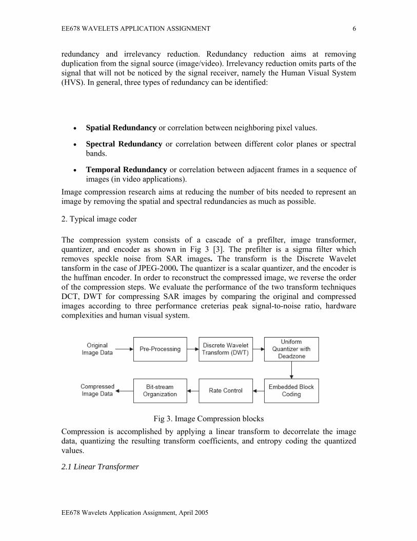
2. Typical image coder The compression system consists of a cascade of a prefilter, image transformer, quantizer, and encoder as shown in Fig 3 [3]. The prefilter is a sigma filter which removes speckle noise from SAR images. The transform is the Discrete Wavelet tansform in the case of JPEG-2000. The quantizer is a scalar quantizer, and the encoder is the huffman encoder. In order to reconstruct the compressed image, we reverse the order of the compression steps. We evaluate the performance of the two transform techniques DCT, DWT for compressing SAR images by comparing the original and compressed images according to three performance creterias peak signal-to-noise ratio, hardware complexities and human visual system.
Fig 3. Image Compression blocks
Compression is accomplished by applying a linear transform to decorrelate the image data, quantizing the resulting transform coefficients, and entropy coding the quantized values.
2.1 Linear Transformer
EE678 Wavelets Application Assignment, April 2005
EE678 WAVELETS APPLICATION ASSIGNMENT 7
Over the years, a variety of linear transforms have been developed which include Discrete Fourier Transform (DFT), Discrete Cosine Transform (DCT), Discrete Wavelet Transform (DWT) and many more, each with its own advantages and disadvantages.
2.2 Quantizer
A quantizer simply reduces the number of bits needed to store the transformed coefficients by reducing the precision of those values. Since this is a many-to-one mapping, it is a lossy process and is the main source of compression in an encoder. Quantization can be performed on each individual coefficient, which is known as Scalar Quantization (SQ). Quantization can also be performed on a group of coefficients together, and this is known as Vector Quantization (VQ). Both uniform and non-uniform quantizers can be used depending on the problem at hand.
2.3 Entropy Encoder
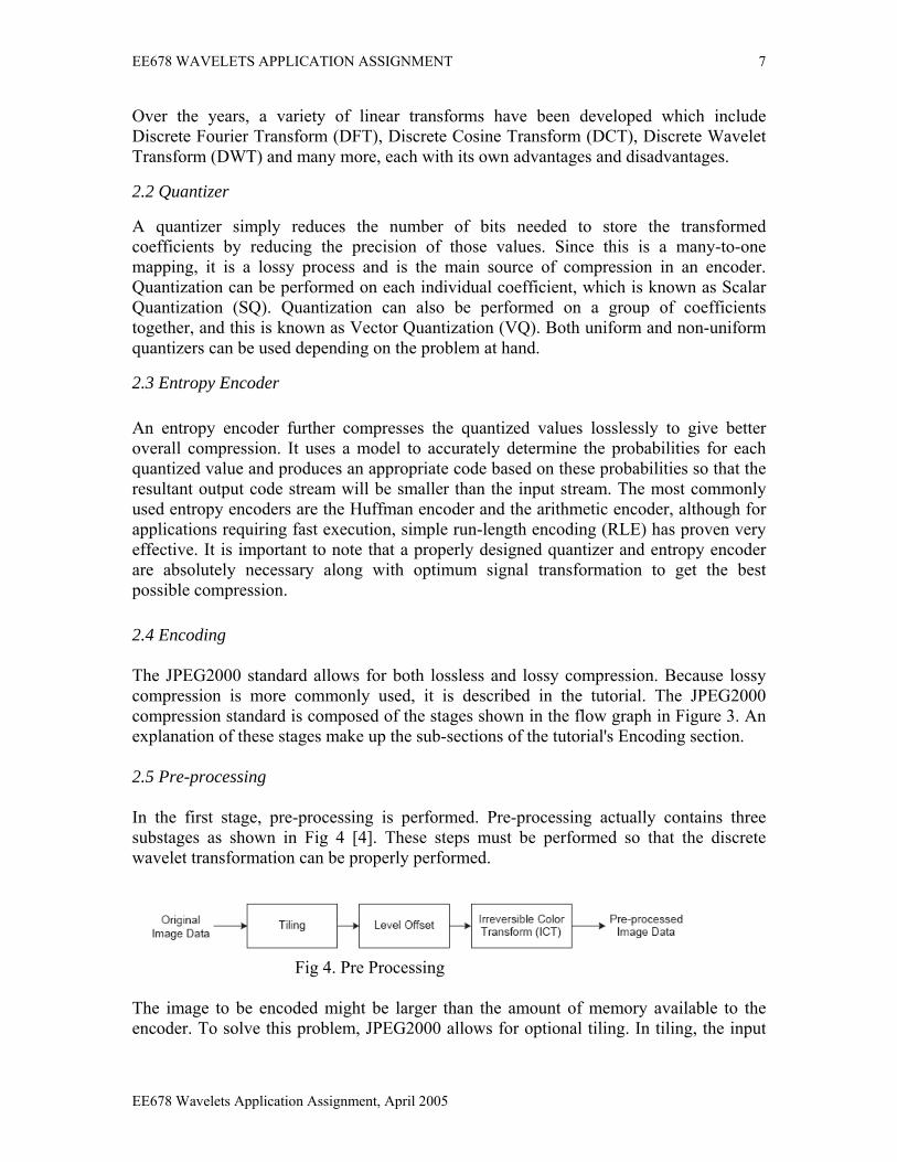
An entropy encoder further compresses the quantized values losslessly to give better overall compression. It uses a model to accurately determine the probabilities for each quantized value and produces an appropriate code based on these probabilities so that the resultant output code stream will be smaller than the input stream. The most commonly used entropy encoders are the Huffman encoder and the arithmetic encoder, although for applications requiring fast execution, simple run-length encoding (RLE) has proven very effective. It is important to note that a properly designed quantizer and entropy encoder are absolutely necessary along with optimum signal transformation to get the best possible compression. 2.4 Encoding The JPEG2000 standard allows for both lossless and lossy compression. Because lossy compression is more commonly used, it is described in the tutorial. The JPEG2000 compression standard is composed of the stages shown in the flow graph in Figure 3. An explanation of these stages make up the sub-sections of the tutorial's Encoding section. 2.5 Pre-processing In the first stage, pre-processing is performed. Pre-processing actually contains three substages as shown in Fig 4 [4]. These steps must be performed so that the discrete wavelet transformation can be properly performed.
Fig 4. Pre Processing The image to be encoded might be larger than the amount of memory available to the encoder. To solve this problem, JPEG2000 allows for optional tiling. In tiling, the input
EE678 Wavelets Application Assignment, April 2005
EE678 WAVELETS APPLICATION ASSIGNMENT 8
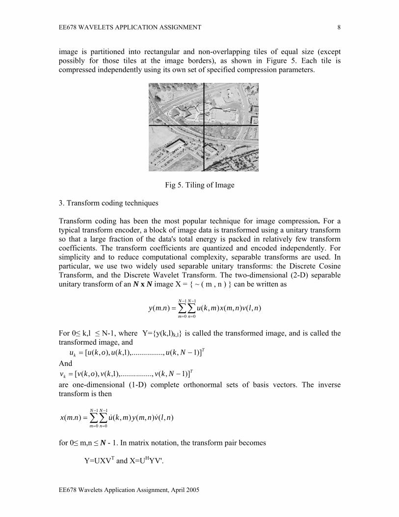
image is partitioned into rectangular and non-overlapping tiles of equal size (except possibly for those tiles at the image borders), as shown in Figure 5. Each tile is compressed independently using its own set of specified compression parameters.
Fig 5. Tiling of Image
3. Transform coding techniques Transform coding has been the most popular technique for image compression. For a typical transform encoder, a block of image data is transformed using a unitary transform so that a large fraction of the data's total energy is packed in relatively few transform coefficients. The transform coefficients are quantized and encoded independently. For simplicity and to reduce computational complexity, separable transforms are used. In particular, we use two widely used separable unitary transforms: the Discrete Cosine Transform, and the Discrete Wavelet Transform. The two-dimensional (2-D) separable unitary transform of an N x N image X = { ~ ( m , n ) } can be written as
∑∑−
=
−
=
=1
0
1
0
),(),(),().(N
m
N
n
nlvnmxmkunmy
For 0≤ k,l ≤ N-1, where Y={y(k,l)k,l} is called the transformed image, and is called the transformed image, and T
k Nkukuokuu )]1,(........,),........1,(),,([ −=And
Tk Nkvkvokvv )]1,(........,),........1,(),,([ −=
are one-dimensional (1-D) complete orthonormal sets of basis vectors. The inverse transform is then
∑∑−
=
−
=
=1
0
1
0
),(),(),().(N
m
N
n
nlvnmymkunmx &&
for 0≤ m,n ≤ N - 1. In matrix notation, the transform pair becomes Y=UXVT and X=UHYV'.
EE678 Wavelets Application Assignment, April 2005
EE678 WAVELETS APPLICATION ASSIGNMENT 9
3.1 The Discrete Cosine Transform (JPEG) The basis vectors of the 2-D discrete cosine transform (DCT) are given by
⎟⎠⎞
⎜⎝⎛ +
==N
kmkamkvmku2
)12(cos)(),(),( π
Where
N
a 1)0( = , N
ka 2)( = , 1 ≤ k ≤ N-1
For highly correlated signals, the DCT has excellent energy compaction properties. The DCT can be regarded as a discrete-time version of the Fourier-Cosine series. It is a close relative of DFT, a technique for converting a signal into elementary frequency components. Thus DCT can be computed with a Fast Fourier Transform (FFT) like algorithm in O(n log n) operations. Unlike DFT, DCT is real-valued and provides a better approximation of a signal with fewer coefficients. The DCT of a discrete signal x(n), n=0, 1, .. , N-1 is defined as:
∑−
=⎟⎠⎞
⎜⎝⎛ +
=1
0 2)12(cos)()(2)(
N
n NmntxuC
NuX
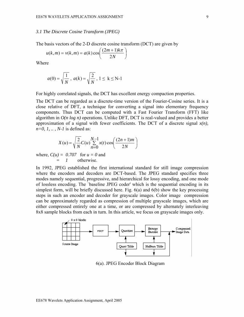
where, C(u) = 0.707 for u = 0 and = 1 otherwise. In 1992, JPEG established the first international standard for still image compression where the encoders and decoders are DCT-based. The JPEG standard specifies three modes namely sequential, progressive, and hierarchical for lossy encoding, and one mode of lossless encoding. The `baseline JPEG coder' which is the sequential encoding in its simplest form, will be briefly discussed here. Fig. 6(a) and 6(b) show the key processing steps in such an encoder and decoder for grayscale images. Color image compression can be approximately regarded as compression of multiple grayscale images, which are either compressed entirely one at a time, or are compressed by alternately interleaving 8x8 sample blocks from each in turn. In this article, we focus on grayscale images only.
6(a). JPEG Encoder Block Diagram
EE678 Wavelets Application Assignment, April 2005
EE678 WAVELETS APPLICATION ASSIGNMENT 10
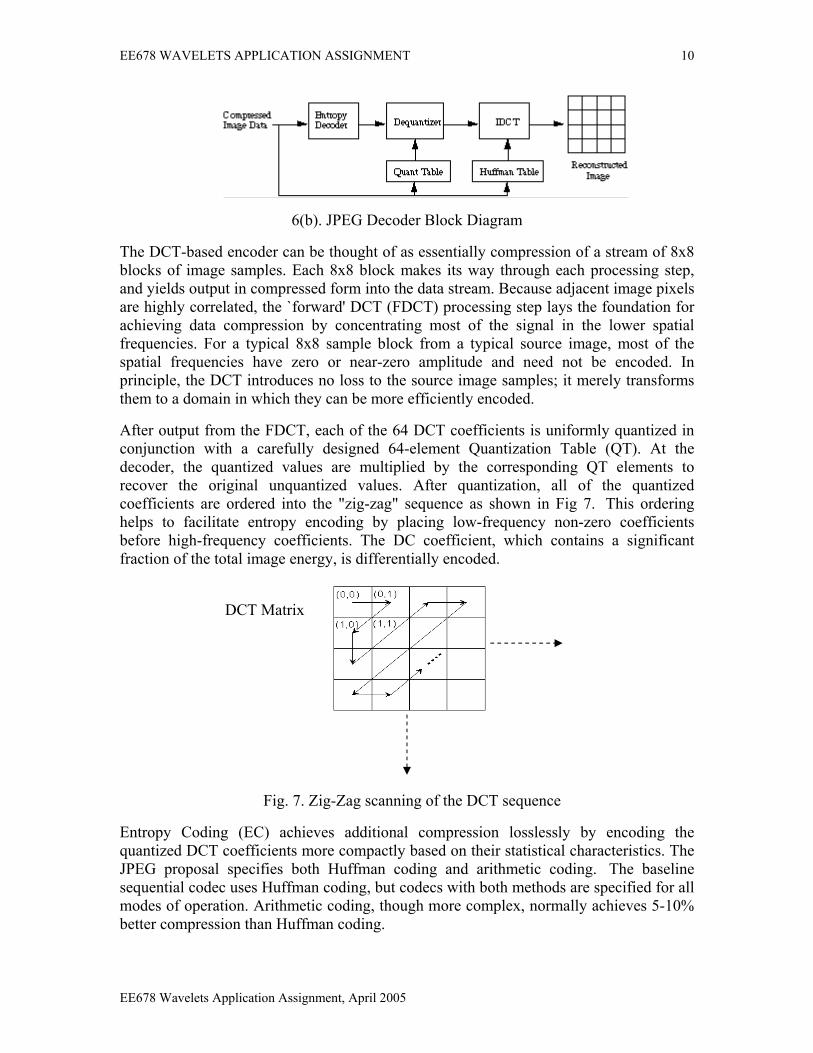
6(b). JPEG Decoder Block Diagram
The DCT-based encoder can be thought of as essentially compression of a stream of 8x8 blocks of image samples. Each 8x8 block makes its way through each processing step, and yields output in compressed form into the data stream. Because adjacent image pixels are highly correlated, the `forward' DCT (FDCT) processing step lays the foundation for achieving data compression by concentrating most of the signal in the lower spatial frequencies. For a typical 8x8 sample block from a typical source image, most of the spatial frequencies have zero or near-zero amplitude and need not be encoded. In principle, the DCT introduces no loss to the source image samples; it merely transforms them to a domain in which they can be more efficiently encoded.
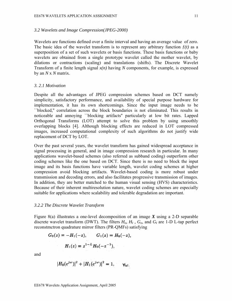
After output from the FDCT, each of the 64 DCT coefficients is uniformly quantized in conjunction with a carefully designed 64-element Quantization Table (QT). At the decoder, the quantized values are multiplied by the corresponding QT elements to recover the original unquantized values. After quantization, all of the quantized coefficients are ordered into the "zig-zag" sequence as shown in Fig 7. This ordering helps to facilitate entropy encoding by placing low-frequency non-zero coefficients before high-frequency coefficients. The DC coefficient, which contains a significant fraction of the total image energy, is differentially encoded.
DCT Matrix
Fig. 7. Zig-Zag scanning of the DCT sequence
Entropy Coding (EC) achieves additional compression losslessly by encoding the quantized DCT coefficients more compactly based on their statistical characteristics. The JPEG proposal specifies both Huffman coding and arithmetic coding. The baseline sequential codec uses Huffman coding, but codecs with both methods are specified for all modes of operation. Arithmetic coding, though more complex, normally achieves 5-10% better compression than Huffman coding.
EE678 Wavelets Application Assignment, April 2005
EE678 WAVELETS APPLICATION ASSIGNMENT 11
3.2 Wavelets and Image Compression(JPEG-2000) Wavelets are functions defined over a finite interval and having an average value of zero. The basic idea of the wavelet transform is to represent any arbitrary function ƒ(t) as a superposition of a set of such wavelets or basis functions. These basis functions or baby wavelets are obtained from a single prototype wavelet called the mother wavelet, by dilations or contractions (scaling) and translations (shifts). The Discrete Wavelet Transform of a finite length signal x(n) having N components, for example, is expressed by an N x N matrix. 3. 2.1 Motivation
Despite all the advantages of JPEG compression schemes based on DCT namely simplicity, satisfactory performance, and availability of special purpose hardware for implementation, it has its own shortcomings. Since the input image needs to be ``blocked,'' correlation across the block boundaries is not eliminated. This results in noticeable and annoying ``blocking artifacts'' particularly at low bit rates. Lapped Orthogonal Transforms (LOT) attempt to solve this problem by using smoothly overlapping blocks [4]. Although blocking effects are reduced in LOT compressed images, increased computational complexity of such algorithms do not justify wide replacement of DCT by LOT.
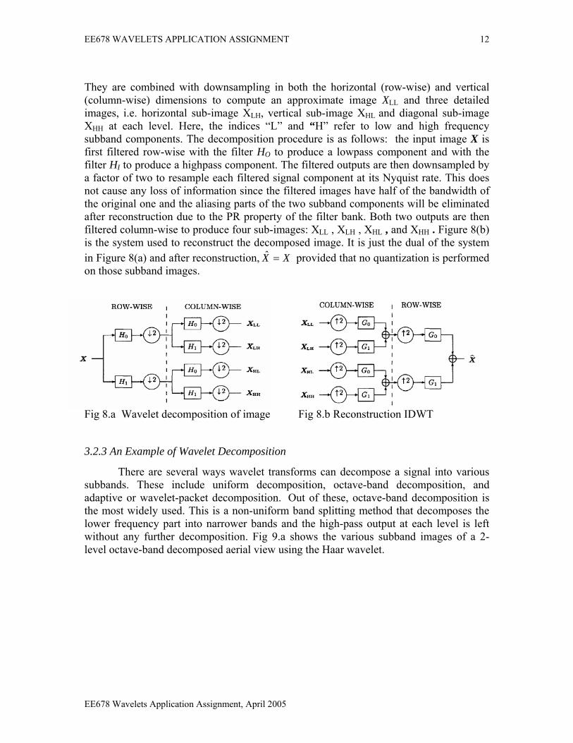
Over the past several years, the wavelet transform has gained widespread acceptance in signal processing in general, and in image compression research in particular. In many applications wavelet-based schemes (also referred as subband coding) outperform other coding schemes like the one based on DCT. Since there is no need to block the input image and its basis functions have variable length, wavelet coding schemes at higher compression avoid blocking artifacts. Wavelet-based coding is more robust under transmission and decoding errors, and also facilitates progressive transmission of images. In addition, they are better matched to the human visual sensing (HVS) characteristics. Because of their inherent multiresolution nature, wavelet coding schemes are especially suitable for applications where scalability and tolerable degradation are important. 3.2.2 The Discrete Wavelet Transform Figure 8(a) illustrates a one-level decomposition of an image X using a 2-D separable discrete wavelet transform (DWT). The filters Ho, HI , Go, and GI are 1-D L-tap perfect reconstmctron quadrature mirror filters (PR-QMFs) satisfying
and
EE678 Wavelets Application Assignment, April 2005
EE678 WAVELETS APPLICATION ASSIGNMENT 12
They are combined with downsampling in both the horizontal (row-wise) and vertical (column-wise) dimensions to compute an approximate image XLL and three detailed images, i.e. horizontal sub-image XLH, vertical sub-image XHL and diagonal sub-image XHH at each level. Here, the indices “L” and “H” refer to low and high frequency subband components. The decomposition procedure is as follows: the input image X is first filtered row-wise with the filter HO to produce a lowpass component and with the filter HI to produce a highpass component. The filtered outputs are then downsampled by a factor of two to resample each filtered signal component at its Nyquist rate. This does not cause any loss of information since the filtered images have half of the bandwidth of the original one and the aliasing parts of the two subband components will be eliminated after reconstruction due to the PR property of the filter bank. Both two outputs are then filtered column-wise to produce four sub-images: XLL , XLH , XHL , and XHH . Figure 8(b) is the system used to reconstruct the decomposed image. It is just the dual of the system in Figure 8(a) and after reconstruction, XX =ˆ provided that no quantization is performed on those subband images.
Fig 8.a Wavelet decomposition of image Fig 8.b Reconstruction IDWT
3.2.3 An Example of Wavelet Decomposition
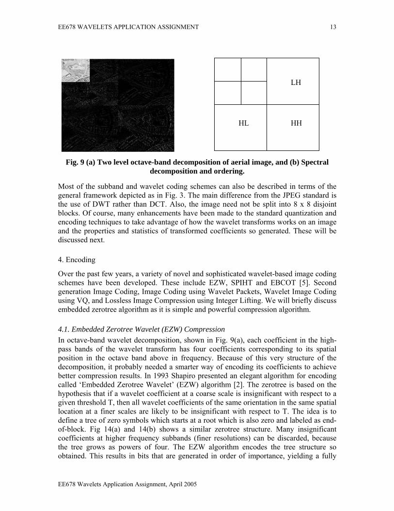
There are several ways wavelet transforms can decompose a signal into various subbands. These include uniform decomposition, octave-band decomposition, and adaptive or wavelet-packet decomposition. Out of these, octave-band decomposition is the most widely used. This is a non-uniform band splitting method that decomposes the lower frequency part into narrower bands and the high-pass output at each level is left without any further decomposition. Fig 9.a shows the various subband images of a 2-level octave-band decomposed aerial view using the Haar wavelet.
EE678 Wavelets Application Assignment, April 2005
EE678 WAVELETS APPLICATION ASSIGNMENT 13
HL
LH
HH
Fig. 9 (a) Two level octave-band decomposition of aerial image, and (b) Spectral decomposition and ordering.
Most of the subband and wavelet coding schemes can also be described in terms of the general framework depicted as in Fig. 3. The main difference from the JPEG standard is the use of DWT rather than DCT. Also, the image need not be split into 8 x 8 disjoint blocks. Of course, many enhancements have been made to the standard quantization and encoding techniques to take advantage of how the wavelet transforms works on an image and the properties and statistics of transformed coefficients so generated. These will be discussed next.
4. Encoding
Over the past few years, a variety of novel and sophisticated wavelet-based image coding schemes have been developed. These include EZW, SPIHT and EBCOT [5]. Second generation Image Coding, Image Coding using Wavelet Packets, Wavelet Image Coding using VQ, and Lossless Image Compression using Integer Lifting. We will briefly discuss embedded zerotree algorithm as it is simple and powerful compression algorithm.
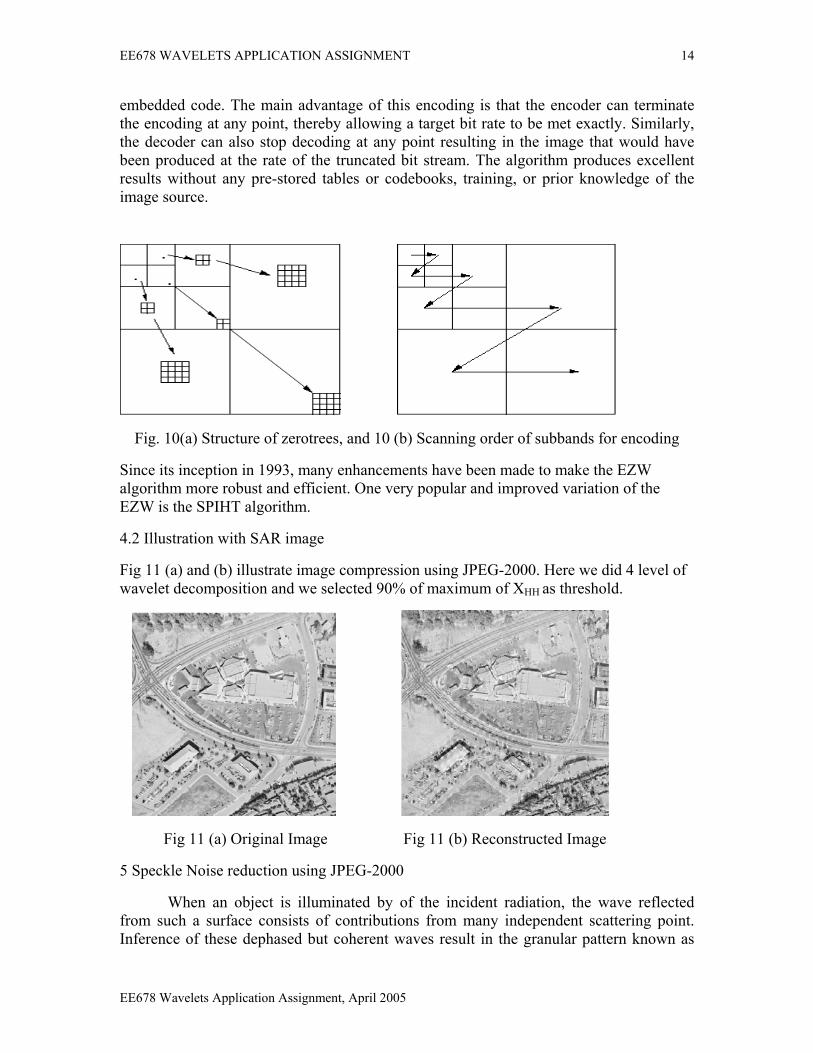
4.1. Embedded Zerotree Wavelet (EZW) Compression In octave-band wavelet decomposition, shown in Fig. 9(a), each coefficient in the high-pass bands of the wavelet transform has four coefficients corresponding to its spatial position in the octave band above in frequency. Because of this very structure of the decomposition, it probably needed a smarter way of encoding its coefficients to achieve better compression results. In 1993 Shapiro presented an elegant algorithm for encoding called ‘Embedded Zerotree Wavelet’ (EZW) algorithm [2]. The zerotree is based on the hypothesis that if a wavelet coefficient at a coarse scale is insignificant with respect to a given threshold T, then all wavelet coefficients of the same orientation in the same spatial location at a finer scales are likely to be insignificant with respect to T. The idea is to define a tree of zero symbols which starts at a root which is also zero and labeled as end-of-block. Fig 14(a) and 14(b) shows a similar zerotree structure. Many insignificant coefficients at higher frequency subbands (finer resolutions) can be discarded, because the tree grows as powers of four. The EZW algorithm encodes the tree structure so obtained. This results in bits that are generated in order of importance, yielding a fully
EE678 Wavelets Application Assignment, April 2005
EE678 WAVELETS APPLICATION ASSIGNMENT 14
embedded code. The main advantage of this encoding is that the encoder can terminate the encoding at any point, thereby allowing a target bit rate to be met exactly. Similarly, the decoder can also stop decoding at any point resulting in the image that would have been produced at the rate of the truncated bit stream. The algorithm produces excellent results without any pre-stored tables or codebooks, training, or prior knowledge of the image source.
Fig. 10(a) Structure of zerotrees, and 10 (b) Scanning order of subbands for encoding
Since its inception in 1993, many enhancements have been made to make the EZW algorithm more robust and efficient. One very popular and improved variation of the EZW is the SPIHT algorithm.
4.2 Illustration with SAR image
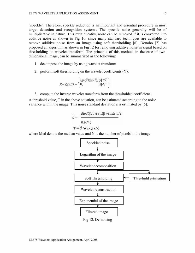
Fig 11 (a) and (b) illustrate image compression using JPEG-2000. Here we did 4 level of wavelet decomposition and we selected 90% of maximum of XHH as threshold.
Fig 11 (a) Original Image Fig 11 (b) Reconstructed Image
5 Speckle Noise reduction using JPEG-2000
When an object is illuminated by of the incident radiation, the wave reflected from such a surface consists of contributions from many independent scattering point. Inference of these dephased but coherent waves result in the granular pattern known as
EE678 Wavelets Application Assignment, April 2005
EE678 WAVELETS APPLICATION ASSIGNMENT 15
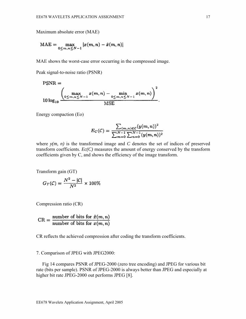
"speckle". Therefore, speckle reduction is an important and essential procedure in most target detection and recognition systems. The speckle noise generally will be of multiplicative in nature. This multiplicative noise can be removed if it is converted into additive noise as shown in Fig 10, since many standard techniques are available to remove additive noise from an image using soft thersholding [6]. Donoho [7] has proposed an algorithm as shown in Fig 12 for removing additive noise in signal based on thresholding its wavelet transform. The principle of this method, in the case of two-dimensional image, can be summarized as the following:
1. decompose the image by using wavelet transform
2. perform soft thresholding on the wavelet coefficients (Y):
3. compute the inverse wavelet transform from the thresholded coefficient. A threshold value, T in the above equation, can be estimated according to the noise variance within the image. This noise standard deviation s is estimated by [5]:
where Med denote the median value and N is the number of pixels in the image.
Speckled noise
Logarithm of the image
Wavelet decomposition
Threshold estimation Soft Thresholding
Wavelet reconstruction
Exponential of the image
Filtered image
Fig 12. De-noising
EE678 Wavelets Application Assignment, April 2005

EE678 WAVELETS APPLICATION ASSIGNMENT 16
Fig 13(a) and (b) are the examples for speckle noise reduction using JPEG-2000
13 (a) Original image of Urban area Original image of Country
13 (b) Original image of Urban area with speckle noise
6. Performance criteria In many image processing applications, mean-squared error is usually used as a performance criterion to compare the quality of a compressed image to its original version. Unfortunately, MSE does not sufficiently reflect those perceptually significant features of images which are often local rather than global in nature [2]. A similar situation holds for SAR data because SAR data will ultimately be interpreted by a human or machines. Since MSE alone is insufficient for measuring and comparing the performance of SAR data compression algorithms, we can evaluate various compression techniques based on a total of six criteria: Mean-squared error (MSE)
where x(m,n), and axe respectively the original image and the compressed image of size N x N. It is well-known that MSE globally measures the average energy of the error image.
),(ˆ nmx
EE678 Wavelets Application Assignment, April 2005
EE678 WAVELETS APPLICATION ASSIGNMENT 17
Maximum absolute error (MAE)
AE shows the worst-case error occurring in the compressed image.
eak signal-to-noise ratio (PSNR)
M P
nergy compaction (Eo)
E
where y(m, n) is the transformed image and C denotes the set of indices of preserved
ransform gain (GT)
transform coefficients. Ec(C) measures the amount of energy conserved by the transform coefficients given by C, and shows the efficiency of the image transform. T
ompression ratio (CR) C
R reflects the achieved compression after coding the transform coefficients.
. Comparison of JPEG with JPEG2000:
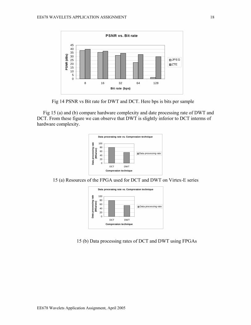
Fig 14 compares PSNR of JPEG-2000 (zero tree encoding) and JPEG for various bit
C 7 rate (bits per sample). PSNR of JPEG-2000 is always better than JPEG and especially at higher bit rate JPEG-2000 out performs JPEG [8].
EE678 Wavelets Application Assignment, April 2005
EE678 WAVELETS APPLICATION ASSIGNMENT 18
12 PSNR comparison of DWT and DCT
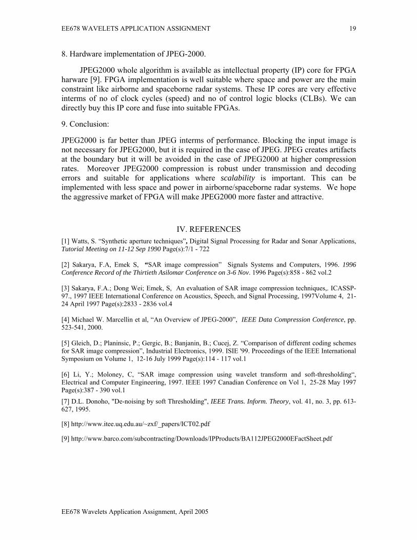
ig 14 PSNR vs Bit rate for DWT and DCT. Here bps is bits per sample Fig 15 (a) and (b) compare hardware complexity and date processing rate of DWT and
F
DCT. From these figure we can observe that DWT is slightly inferior to DCT interms of hardware complexity.
Data processing rate vs. Compression technique
0
20
40
60
80
100
DCT DWT
Compression technique
Dat
a pr
oces
sing
rat
e (M
Sa/
sec)
Data processing rate
15 (a) Resources of the FPGA used for DCT and DWT on Virtex-E series
Data processing rate vs. Compression technique
0
20
40
60
80
100
DCT DWT
Compression technique
Dat
a pr
oces
sing
rat
e (M
Sa/s
ec)
Data processing rate
PSNR vs. Bit rate
05
1015202530354045
8 16 32 64 128
Bit rate (bps)
PSNR
(dB
s)
JPEGZTE
15 (b) Data processing rates of DCT and DWT using FPGAs
EE678 Wavelets Application Assignment, April 2005
EE678 WAVELETS APPLICATION ASSIGNMENT 19
8. Hardware implementation of JPEG-2000.
JPEG2000 whole algorithm is available as intellectual property (IP) core for FPGA harware [9]. FPGA implementation is well suitable where space and power are the main constraint like airborne and spaceborne radar systems. These IP cores are very effective interms of no of clock cycles (speed) and no of control logic blocks (CLBs). We can directly buy this IP core and fuse into suitable FPGAs.
9. Conclusion:
JPEG2000 is far better than JPEG interms of performance. Blocking the input image is not necessary for JPEG2000, but it is required in the case of JPEG. JPEG creates artifacts at the boundary but it will be avoided in the case of JPEG2000 at higher compression rates. Moreover JPEG2000 compression is robust under transmission and decoding errors and suitable for applications where scalability is important. This can be implemented with less space and power in airborne/spaceborne radar systems. We hope the aggressive market of FPGA will make JPEG2000 more faster and attractive.
IV. REFERENCES [1] Watts, S. “Synthetic aperture techniques”, Digital Signal Processing for Radar and Sonar Applications, Tutorial Meeting on 11-12 Sep 1990 Page(s):7/1 - 722 [2] Sakarya, F.A, Emek S, “SAR image compression” Signals Systems and Computers, 1996. 1996 Conference Record of the Thirtieth Asilomar Conference on 3-6 Nov. 1996 Page(s):858 - 862 vol.2 [3] Sakarya, F.A.; Dong Wei; Emek, S, An evaluation of SAR image compression techniques,. ICASSP-97., 1997 IEEE International Conference on Acoustics, Speech, and Signal Processing, 1997Volume 4, 21-24 April 1997 Page(s):2833 - 2836 vol.4 [4] Michael W. Marcellin et al, “An Overview of JPEG-2000”, IEEE Data Compression Conference, pp. 523-541, 2000. [5] Gleich, D.; Planinsic, P.; Gergic, B.; Banjanin, B.; Cucej, Z. “Comparison of different coding schemes for SAR image compression”, Industrial Electronics, 1999. ISIE '99. Proceedings of the IEEE International Symposium on Volume 1, 12-16 July 1999 Page(s):114 - 117 vol.1 [6] Li, Y.; Moloney, C, “SAR image compression using wavelet transform and soft-thresholding“, Electrical and Computer Engineering, 1997. IEEE 1997 Canadian Conference on Vol 1, 25-28 May 1997 Page(s):387 - 390 vol.1
[7] D.L. Donoho, "De-noising by soft Thresholding", IEEE Trans. Inform. Theory, vol. 41, no. 3, pp. 613-627, 1995.
[8] http://www.itee.uq.edu.au/~zxf/_papers/ICT02.pdf
[9] http://www.barco.com/subcontracting/Downloads/IPProducts/BA112JPEG2000EFactSheet.pdf
EE678 Wavelets Application Assignment, April 2005