
Sapphire TSV & TWS Series Digital Thermostat for Direct ... · PDF fileSapphire TSV & TWS...
33
Sapphire TSV & TWS Series Digital Thermostat for Direct Expansion Split Systems and Self Contained Units
Transcript of Sapphire TSV & TWS Series Digital Thermostat for Direct ... · PDF fileSapphire TSV & TWS...

Sapphire TSV & TWS SeriesDigital Thermostat
forDirect Expansion Split Systems
and Self Contained Units
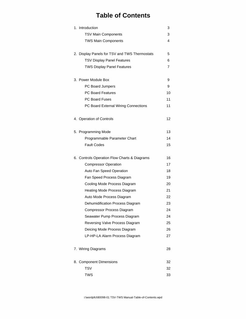
Table of Contents
1. Introduction 3
TSV Main Components 3
TWS Main Components 4
2. Display Panels for TSV and TWS Thermostats 5
TSV Display Panel Features 6
TWS Display Panel Features 7
3. Power Module Box 9
PC Board Jumpers 9
PC Board Features 10
PC Board Fuses 11
PC Board External Wiring Connections 11
4. Operation of Controls 12
5. Programming Mode 13
Programmable Parameter Chart 14
Fault Codes 15
6. Controls Operation Flow Charts & Diagrams 16
Compressor Operation 17
Auto Fan Speed Operation 18
Fan Speed Process Diagram 19
Cooling Mode Process Diagram 20
Heating Mode Process Diagram 21
Auto Mode Process Diagram 22
Dehumidification Process Diagram 23
Compressor Process Diagram 24
Seawater Pump Process Diagram 24
Reversing Valve Process Diagram 25
Deicing Mode Process Diagram 26
LP-HP-LA Alarm Process Diagram 27
7. Wiring Diagrams 28
8. Component Dimensions 32
TSV 32
TWS 33
i:\wordpfct\80098-01 TSV-TWS Manual-Table-of-Contents.wpd

1. Introduction
The Aqua-Air Sapphire TSV and TWS Series Direct Expansion (D/X) Thermostats have beendesigned specifically to operate either split systems or self contained units. These systems willusually have a compressor, reversing valve, seawater pump and fan motor(s) . All of thesecomponents can be regulated by these thermostats.
The only difference between the TSV and the TWS models is the display head appearance. TheTSV has a Vimar® brand bezel surrounding the display and button portion of the display head. TheTWS was designed as a retrofit for the older Aqua-Air TW-2000 digital thermostat. The TWSdisplay head is exactly the same size as the older TW-2000. Both controls operate in exactly thesame way.
The TSV Thermostat is comprised of the following main components:
1. Display Panel ( TSV-01 )2. Display Cable ( TSWDC-15 )3. Power Module Box ( TSV-02 )4. Room Air Sensor ( TW2-SENSOR-07 )5. Outside Air Temperature Sensor ( TW2-SENSOR-XX ) (optional)
3

The TWS Thermostat is comprised of the following main components:
1. Display Panel ( TWWS-01 )2. Display Cable ( TSWDC-15 )3. Power Module Box ( TSV-02 )4. Room Air Sensor ( TW2-SENSOR-07 )5. Outside Air Temperature Sensor ( TW2-SENSOR-XX ) (optional)
4

2. Display Panel
The TSV-01 and TWWS-01 Display Panel is the user interface with the TSV Thermostat. It allowsthe user to make all necessary changes to operating modes, temperature settings and fan speedsettings. It also allows the user to make changes to a set of Programming Parameters thatcontrols many of the features of the thermostat.
The Display Panel has been designed to use the Vimar Idea Series metal bezels giving you analmost unlimited number of color options to match any decor. The bezel snaps on and off easilyand it hides all of the mounting screws for the display panel
On the following page is a diagram showing all of the features of the Display Panels. The featuresare applicable for both TSV-01 & TWWS-01 display heads. Each feature has a number associatedwith it.
Features of the TSV-01 and TWWS-01 Display Panels are:
1. MODE BUTTON - The Mode Button is used to select one of the four operatingmodes and standby (off) mode. Pressing and releasing the Mode Button willadvance you to the next mode. Continue to do this until you have reached thedesired mode. The available modes are as follows:
STANDBY Thermostat is OFF, no Cooling or Heating functions areavailable. The fan can be operated in the Manual mode.Indicated by LED 11.
DEHUMIDIFICATION Thermostat is in the Dehumidification Mode indicated byLED 14.
COOLING Thermostat is in the Cooling Mode only, indicated byLED 15.
HEATING Thermostat is in the Heating Mode only, indicated byLED 16.
AUTO Thermostat is in the Auto Mode where it willautomatically choose between Cooling and Heating asthe room temperature dictates. This mode is indicatedby LED 17.
2. FAN BUTTON - The Fan Button is used to select between AUTO and MANUAL FanSpeed Control as indicated by LED’s 12 and 13 respectively. To go from AUTO toMANUAL Mode press the Fan Button once. To change Fan Speeds while inMANUAL Mode press the Fan Button once and then the Up or Down Button toincrease or decrease, respectively, the Fan Speed. To switch from MANUAL toAUTO Mode press the Fan Button twice
5

6

7

3. UP BUTTON - The Up Button is used to increase values for set points, fan speedsand programmable parameters. During normal operation, momentarily pressing theUp Button will display the Set Point. Continued pressing of the Up Button willincrease the Set Point
4. DOWN BUTTON - The Down Button is used to decrease values for set points, fanspeeds and programmable parameters. During normal operation, momentarilypressing the Down Button will display the Set Point. Continued pressing of the DownButton will decrease the Set Point.
To view the Outside Air Temperature (OAT) sensed by the optional OAT Sensor:
1. Press and HOLD the Down Button (4)2. Press and RELEASE the Up Button (3)
5. FAN SPEED LED’s - These six LED’s indicate the current Fan Speed 1-6. LowSpeed (#1) is the left most LED and High Speed (#6) is indicated by the LED on thefar right.
6. 100°F+ LED - Indicates that the actual temperature displayed is in excess of 100°F. Add the value displayed to 100 to get the actual temperature. If the 100°F LEDis lit and the display shows 10 then the actual temperature would be 110°F.
7. MAIN DISPLAY - This is a 2 digit, 7 segment LED display. Normally the currentroom temperature is displayed. It can also display the Set Point, WaterTemperature, Programmable Parameters and Alarm codes.
8. COMPRESSOR LED - This LED indicates if the Compressor output has been turnedon (in either the Cooling or Heating mode).
9. FACEPLATE AIR SENSOR - The TSV can use either this Faceplate Air Sensor tosense the room temperature or the Air Sensor that is plugged into the Power ModulePC Board. This is selected by Programmable Parameter B1. If the Faceplate Sensoris used it is not necessary to have the Air Sensor plugged into the PC Board.
10. ALARM LED - Indicates that the control is in a fault condition.
11. STANDBY MODE LED - Indicates that the control is in the Standby Mode. AllCooling and Heating functions are turned off. If the fan is in the Auto Mode then itwill be turned off. If the Fan is in the Manual Mode then the Fan will still operate atthe last fan speed selected.
12. MANUAL FAN LED - Indicates the Fan Speed is in the Manual Speed SelectionMode
13. AUTO FAN LED - Indicates the Fan Speed is in the Automatic Speed SelectionMode
14. DEHUMIDIFICATION MODE LED - Indicates that the control is in theDehumidification Mode
15. COOLING MODE LED - Indicates the control is in the Cooling Mode8

16. HEATING MODE LED - Indicates the control is in the Heating Mode
17. AUTO COOL/HEAT MODE LED - Indicates the control is in the Automatic Coolingor Heating Mode. In this mode the control will automatically select, based on theroom temperature and the set point, whether the control is operating in the Coolingor Heating Mode.
3. Power Module Box
The Power Module Box is comprised of the Main Power PC Board enclosed inside of analuminum enclosure. The PC Board’s main features are shown on the following page.
POWER MODULE PC BOARD JUMPERS
Jumper Description Type Specification Notes
JP1Chillwater / Direct
Expansion SelectionWire
C/W: Jumper CutD/X: Jumper Not Cut
Do not cut withpower applied toboard.
JP3Compressor Relay
Test3 pos.
pinInstall jumper in positions 1 &2 to energize the compressor
JP4 Pump Relay Test3 pos.
pinInstall jumper in positions 1 &2 to energize the pump
JP5Reversing Valve
Relay Test3 pos.
pin
Install jumper in positions 1 &2 to energize the reversingvalve
JP6 Low Pressure Switch WireLPS connected to J7,positions 2 & 3: CutNo LPS connected: Not Cut
9

10

POWER MODULE PC BOARD FUSES
Fuse DescriptionFuse Amperage
RatingFuse Size
Part Number
F1 Protects against a line voltage short circuiton the primary side of the transformer TX
500 mA( 1/2 A )
5mm x 20mmTWS-PCBFUSE1
F2Protects against a short circuit on theCompressor, Reversing Valve or SeawaterPump circuits.
20 A5mm x 20mm
TWS-PCBFUSE1
F3Protects against a control circuit short circuiton the secondary side of the transformer TX
500 mA( 1/2 A )
5mm x 20mmTWS-PCBFUSE1
Basic External Wiring Connections to theTSV and TWS PC Board Located in the Power Module Box

4. Operation
Below are the steps necessary for the basic operation of the control.
Entering the Cooling ModePress and release the Mode Button (1) until the Cooling Mode LED (15) is lit.
Entering the Heating ModePress and release the Mode Button (1) until the Heating Mode LED (16) is lit.
Automatic (Auto) Cool / Heat ModePress and release the Mode Button (1) until the Auto LED (17) is lit
Entering the Dehumidification ModePress and release the Mode Button (1) until the Dehumidification Mode LED (14) is lit.
Turn the Control OFF (Standby Mode)Press and release the Mode Button (1) until the Standby Mode LED (11) is lit.
View the Set Point TemperaturePress and release either the Up Button (3) or the Down Button (4).
Increasing the Set Point TemperaturePress and release the Up Button (3) until you reach the desired temperature
Decreasing the Set Point TemperaturePress and release the Down Button (4) until you reach the desired temperature
Putting the Fan Mode into ManualPress and release the Fan Button (2) until the Manual Fan LED (12) is lit
Increasing the Fan Speed in the Manual Fan ModePress and release the Fan Button (2) and then press and release the Up Button (3) untilyou reach the desired speed as indicated by the Fan Speed LED’s (5).
Decreasing the Fan Speed in the Manual Fan ModePress and release the Fan Button (2) and then press and release the Down Button (4) untilyou reach the desired speed as indicated by the Fan Speed LED’s (5).
Putting the Fan Mode into AutoPress and release the Fan Button (2) twice
Displaying the Outside Air TemperaturePress and hold the Down Button (4) then press and release the Up Button (3)
Changing the Fan Speeds in the Standby ModePress and release the Up Button (3) or the Down Button (4) until the desired speed isreached. To turn the fan off in the Standby Mode press the Down Button (4) until all of theFan Speed LED’s are off.
12

5. Entering the Programming Mode
There are currently 17 different programmable parameters in the TSV and TWSThermostats. All of these parameters can be changed from the Display Panel with some simplekeystrokes.
The Program Mode can ONLY be entered while the control is in the Standby Mode
To Program the TSV Control:
1. Press the Mode Button until the control is in the Standby Mode which is indicatedby the Standby Mode LED (11)
2. Press the Up Button and the Down Button at the SAME time. The firstProgrammable Parameter code “P1" will appear in the window for 2 seconds andthen the P1 setting that is currently stored in the control will appear.
3. To change the parameter setting press and release the Up or Down Buttons.
4. The Fan Button advances you to the next parameter. Advancing to the nextparameter SAVES the previous parameter setting. If you do not advance to the nextparameter the setting WILL NOT BE SAVED unless you press the Mode Button toexit the Programming Mode (see 5 below).
5. Pressing the Mode Button exits the Programming Mode. Any changes made to anyof the parameter settings will be saved.
6. If you do not press any buttons for 30 seconds the control will automatically exit fromthe Program Mode. The last parameter change will NOT BE SAVED.
13
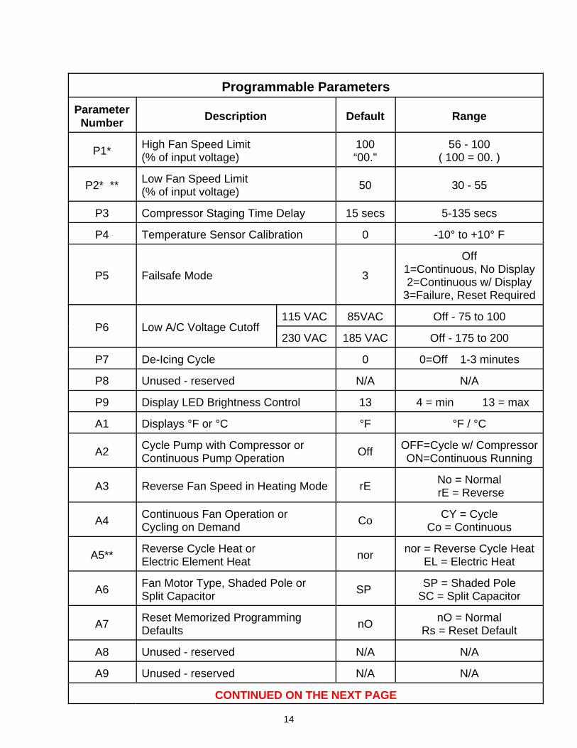
Programmable Parameters
ParameterNumber
Description Default Range
P1*High Fan Speed Limit(% of input voltage)
100“00."
56 - 100( 100 = 00. )
P2* **Low Fan Speed Limit (% of input voltage)
50 30 - 55
P3 Compressor Staging Time Delay 15 secs 5-135 secs
P4 Temperature Sensor Calibration 0 -10° to +10° F
P5 Failsafe Mode 3
Off1=Continuous, No Display2=Continuous w/ Display
3=Failure, Reset Required
P6 Low A/C Voltage Cutoff115 VAC 85VAC Off - 75 to 100
230 VAC 185 VAC Off - 175 to 200
P7 De-Icing Cycle 0 0=Off 1-3 minutes
P8 Unused - reserved N/A N/A
P9 Display LED Brightness Control 13 4 = min 13 = max
A1 Displays °F or °C °F °F / °C
A2Cycle Pump with Compressor orContinuous Pump Operation
OffOFF=Cycle w/ CompressorON=Continuous Running
A3 Reverse Fan Speed in Heating Mode rENo = Normal rE = Reverse
A4Continuous Fan Operation or Cycling on Demand
CoCY = Cycle
Co = Continuous
A5**Reverse Cycle Heat or Electric Element Heat
nornor = Reverse Cycle Heat
EL = Electric Heat
A6Fan Motor Type, Shaded Pole or Split Capacitor
SP SP = Shaded Pole
SC = Split Capacitor
A7Reset Memorized ProgrammingDefaults
nOnO = Normal
Rs = Reset Default
A8 Unused - reserved N/A N/A
A9 Unused - reserved N/A N/A
CONTINUED ON THE NEXT PAGE
14

Programmable Parameters (cont)
ParameterNumber
Description Default Range
b1Air Temperature Sensed from theDisplay Panel or the Air Sensorconnected to the PC Board
onon = PC Board
of = Display Panel
b2 Delay Before Fan Turns Off 30s 30 - 199 seconds
* P1 and P2 values are expressed as a percentage of the input voltage. If the setting for P1is 90 then the maximum voltage output at high fan speed (speed 6) will be approximately90% of the input voltage. As you are changing the settings in P1 and P2 the fan will operateand change according to the settings you are entering.
** If Electric Heat is selected ( A5 = EL ) then P2 must NOT be set lower than 50 andparameter b2 must be set to a minimum of 60 seconds.
FAULT CODES
Code Description
AAAir Sensor Failure or Disconnected. If you get this error code and you intend touse the air sensor on the Display Panel change Parameter b1 to “of”.
E1Display cable damaged. Check to see if the cable has been cut or otherwisedamaged.
HPHigh Refrigerant Pressure. The seawater flow to the condensing unit has beeninterrupted
LALow Voltage Input to Power Module Box. Check your incoming voltage to thePower Module Box and verify that it is within +/-10% of the rated voltage
LPLow Refrigerant Pressure. This fault can be due to restricted air flow throughthe evaporator coil or a refrigerant leak.
15
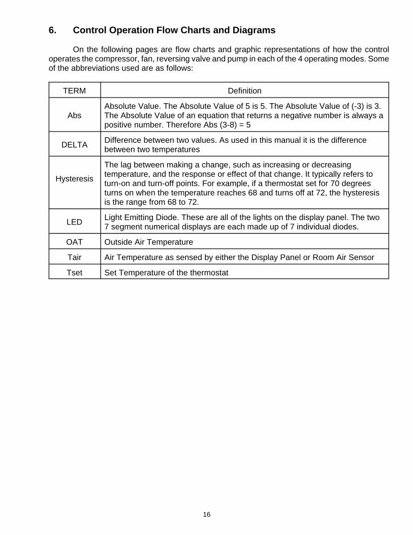
6. Control Operation Flow Charts and Diagrams
On the following pages are flow charts and graphic representations of how the controloperates the compressor, fan, reversing valve and pump in each of the 4 operating modes. Someof the abbreviations used are as follows:
TERM Definition
AbsAbsolute Value. The Absolute Value of 5 is 5. The Absolute Value of (-3) is 3.The Absolute Value of an equation that returns a negative number is always apositive number. Therefore Abs (3-8) = 5
DELTADifference between two values. As used in this manual it is the differencebetween two temperatures
Hysteresis
The lag between making a change, such as increasing or decreasingtemperature, and the response or effect of that change. It typically refers toturn-on and turn-off points. For example, if a thermostat set for 70 degreesturns on when the temperature reaches 68 and turns off at 72, the hysteresisis the range from 68 to 72.
LEDLight Emitting Diode. These are all of the lights on the display panel. The two7 segment numerical displays are each made up of 7 individual diodes.
OAT Outside Air Temperature
Tair Air Temperature as sensed by either the Display Panel or Room Air Sensor
Tset Set Temperature of the thermostat
16

17
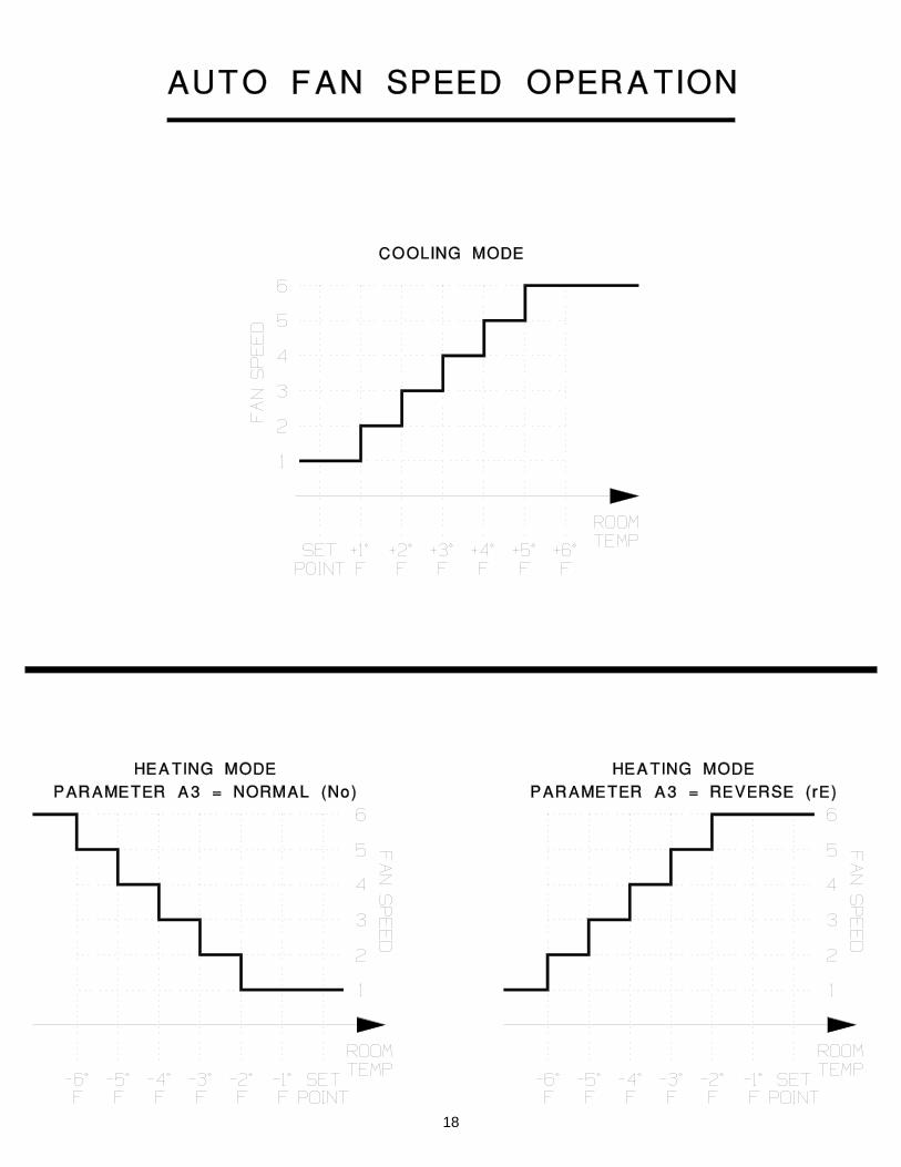
18

FAN
CYCLING MODE P13
HEATING orCOOLING
AUTOMODE
DELTA < 1
YES
YES
DELTA > 6
YES
SPEED = 6SPEED = 1 SPEED = DELTA
NO
FAN OFF
NO
CON
PROGRAMMED SPEED
NO
TIMER > b2
NO
YES
NO
YES
CYC
FAN OPERATION & SPEED SELECTION
Normal Fan Operation DELTA = Abs( Tair - Tset )
Reverse Fan OperationDELTA = Abs[ Abs( Tair - Tset) - 6 ]19

COOL
AIRPROBE
YES
COOLING MODE
MIN FAN SPEEDOR
MANUAL SPEEDCOMPRESSOR
OFF
Tair>(Tset+1)
YES
SELECTED FAN SPEED
Tair < ( Tset - 1)
YES
NO
NO
NO
COMPRESSOR ON
REVERSING VALVE inCOOLING POSITION
(OFF)
20

HEAT
AIRPROBE
YES
HEATING MODE
MIN FAN SPEEDOR
MANUAL SPEEDCOMPRESSOR
OFF
Tair<(Tset-1)
YES
SELECTED FAN SPEED
Tair > ( Tset + 1)
YES
NO
NO
NO
COMPRESSOR ON
REVERSING VALVE inHEATING POSITION
(ON)
21

AUTO
HEATor
COOL
COOL
AUTO MODE
(Tair - Tset) < -2
HEATING MODE
NOYES
(Tair - Tset) > 2
HEAT
COOLING MODE
NO
COOLING MODE
YES
22

DEHUMIDIFICATIONMODE
SELECTINGDEHUMIDIFICATION
DEHUMIDIFICATION MODE
FAN ON
WAIT 1MINUTE
NO
YES
NO
YES
WAIT 30MINUTES
YES
NO
COOLING CYCLE
WAIT 1 HOURor until
( Tair - Tset ) < -2
NO
YES
WAIT4 HOURS
YES
NO
23

COMPRESSOR
FLAGCOMPRESSOR
COMPRESSOR
ON
COMPRESSORON
TIMER > P3
YES
COMPRESSOROFF
NO
OFF
P3 REFERS TOPROGRAMMABLEPARAMETER P3
SEAWATERPUMP
CYCLE ORCONTINUOUS
A2
SEAWATER PUMP
OFF
PUMP OFF
COMPRESSORON
OFF
PUMP ON
ON
ON A2 REFERS TOPROGRAMMABLEPARAMETER A2CONT
CYC
24

REVERSING VALVE
POWER UP
REVERSING VALVE
NO
VALVE NOTTOGGLE
COOLINGor
HEATINGCALL
YES
VALVETOGGLE
NO
YES
TIME SYSTEMIS OFF > 75s
YES
NO
25

DEICING
COOLING MODE
DEICING MODE
YES
HEATING MODE
UNIT WITHREVERSING VALVE
YES
TEMPERATURENOT CHANGED
FOR 1h
YES
DEICING CYCLE
YES
TIMER < P7
YES
COOLING MODE
NO
NO
NO
NO
NO
P7 REFERS TO PROGRAMMABLE PARAMETER P726

STARTLP - HP - LA ALARM (P5)
NUMBER OFFAILURESEQUALS 4
NO
MANUAL RESETREQUIRED
RESTART SYSTEMAFTER 90 sec
LP HP LADISABLED
YES
LP / HP / LADISPLAYED
LP ENABLEHP ENABLELA ENABLE
FAILSAFEMODEP5 = 3
YES
LP / HP / LADISPLAYED
LP ENABLEHP ENABLELA ENABLE
FAILSAFEMODEP5 = 2
YES
NO
NO
LP / HP / LANOT
DISPLAYED
LP ENABLEHP ENABLELA ENABLE
FAILSAFEMODEP5 = 1
YES
NOOFF MODE
YES
NO
P5 REFERS TO PROGRAMMABLE PARAMETER P5LP Low Refrigerant Pressure FaultHP High Refrigerant Pressure Fault
LA Low Input Voltage
27

TERMINAL BLOCK - ENLARGED VIEiAJ
Comp Comp Pump Pump Valve AC AC FAN FAN
HIGH REFRIGERANT
PRESSURE SNITCH
-
-
,--
L-2 L-j L-j L-2 L-2 L-j
n -
I
[] ®
~
m E+-~ =" CD ~--~
=
UNIT PONER INPUT
SEE NOTE 1 BELON
I I
o
~~ ~ jt~[""+---------'
LJ Lll,
UNIT BLOWER [SHADED POLE
/) w"em
.. ----------~-=-,
.
SEANA TER PUMP
- D ~~ ----------------~ CY)
=
LON REFRIGERANT
PRESSURE SNITCH
I
, N ~---------------------~ w =
I NOTE 1 POWER INPUT I
",.p<:V TERMINAL GRND ~C)v 6 '1 LUG
115 L N 230 Ll L2
\J ( ~ )!
UNIT BLOWER [PSC)
\
~'=-'-------FAN MOTOR
'---------1 RUN CAPACITOR
REVERSING VALVE SOLENOID COIL
PTCR ST ART ASSIST
DEVICE
OVERLOAD
COMPRESSOR '\ -~ \ _ [1-+-+--+-+---1 5
~~---------------~
& @00 ~=~ ~ [}J2 MARINE Sy~T~g~DITIONING
SELF CONTAINED UNIT NIRING NITH SAPPHIRE DIGITAL THERMOSTAT iw/HIGH Il LON PRESSURE SNITCHI
=':' 40112H2J3J i'J'''' 58 I em 06-11-06
28

UNIT
111 11;II[N~'11 ~ iF I IF~ ~R;~ ~II g I BLOWER [SHADED POLE
UNIT BLOWER [PSC)
Comp Comp Pump Pump Valve AC AC FAN FAN
\J~ 1/) w"em
HIGH PRESSURE\ JJMPER
L-2 L-j L-j L-2 L-2 L-j
~T G~
IT "-
\
I~~ I " I c "-
;0' . .
:Bt K;)
n ~
[I
[] ~
®
~
ml>++-------" '=== "
UNIT POHER INPUT
SEE NOTE 1 BELOH
I I
o
CD E+--~
~L~'+-______ ~
• -c ~'=-
SEANA TER PUMP
~~ ,LSJ~ LJ Lll W----------~
c==J ~~~-------------~ ~
~ , N ~--------------------~ w =
I -~
I NOTE 1 POWER INPUT I
"'~<:v TERMINAL GRNO ~C)v 6 t LUG
115 LNG -=k=-230 L1 L2
HIGH REFRIGERANT
PRESSURE SWITCH
FAN MOTOR '---------1 RUN CAPACITOR
REVERSING VALVE SOLENOID COIL
/---'---
PTCR ST ART ASSIST
DEVICE
/ ~~
\ RUN
CAPACITOR
~-----------
~o
;Z: OVERLOAD . 0
-cg COMPRESSOR
\~-------~~
~~--------------~
& @00 ~=~ ~ [}J2 MARINE SY~T~g~DITIONING
SELF CONTAINED UNIT HIRING HITH SAPPHIRE DIGITAL THERMOSTAT
iw/HIGH PRESSURE JUMPER) =':' 40112H2J3K I i'J'''' 58 I em 06-11-06 "'''' NONE I ~'m ON I ~¥~'CN I ""
29

TERMINAL BLOCK - ENLARGED VIEW
III 112113114115116111711811 ~ I Comp Camp Pump Pump Valve AC AC FAN FAN
HIGH REFRIGERANT
PRESSURE SWITCH
L-2 L-j L-j L-2 L-2 L-j
UNIT POWER INPUT
SEE NOTE 1 BELOW
o
DO ~I H I CD ~---------" ,---------t" "' -
cO· . . , . -
SEAWATER PUMP VOL T AGE SAME
AS SYSTEM VOLTAGE
F AN COIL UNIT
VOL T AGE SAME AS SYSTEM VOLTAGE
REVERSING VALVE
SOLENOID COIL
\ rEi ART RELAY
~ I~
START ~
CAPACITOR! !/~~II-'\:--'I'I-_-----" / £T~ ~1J9: I) f II 0 IIII c I I
RESISTOR ~ RUN~~Y CAPACITOR
COMPRESSOR
:B~ ~ fr"r----------------------------------J
LOW REFRIGERANT
PRESSURE SWITCH
® ~ I NOTE 1 POWER INPUT I
~-{J<V TERMINAL GRND ~vv 6 7' LUG
ll5 L N 230 Ll L2
& @00 ~=~ ~ [}J2 MARINE SY~T~g~DITIONING
CONDENSING UNIT NIRING NITH SAPPHIRE DIGITAL THERMOSTAT iw/HIGH Il LON PRESSURE SNITCHI
=':' 4009-4 7DI i'J'''' 58 1 em 06-11-06 SVLE NON E ~VED 0 N I ~¥~Irn j REV
30
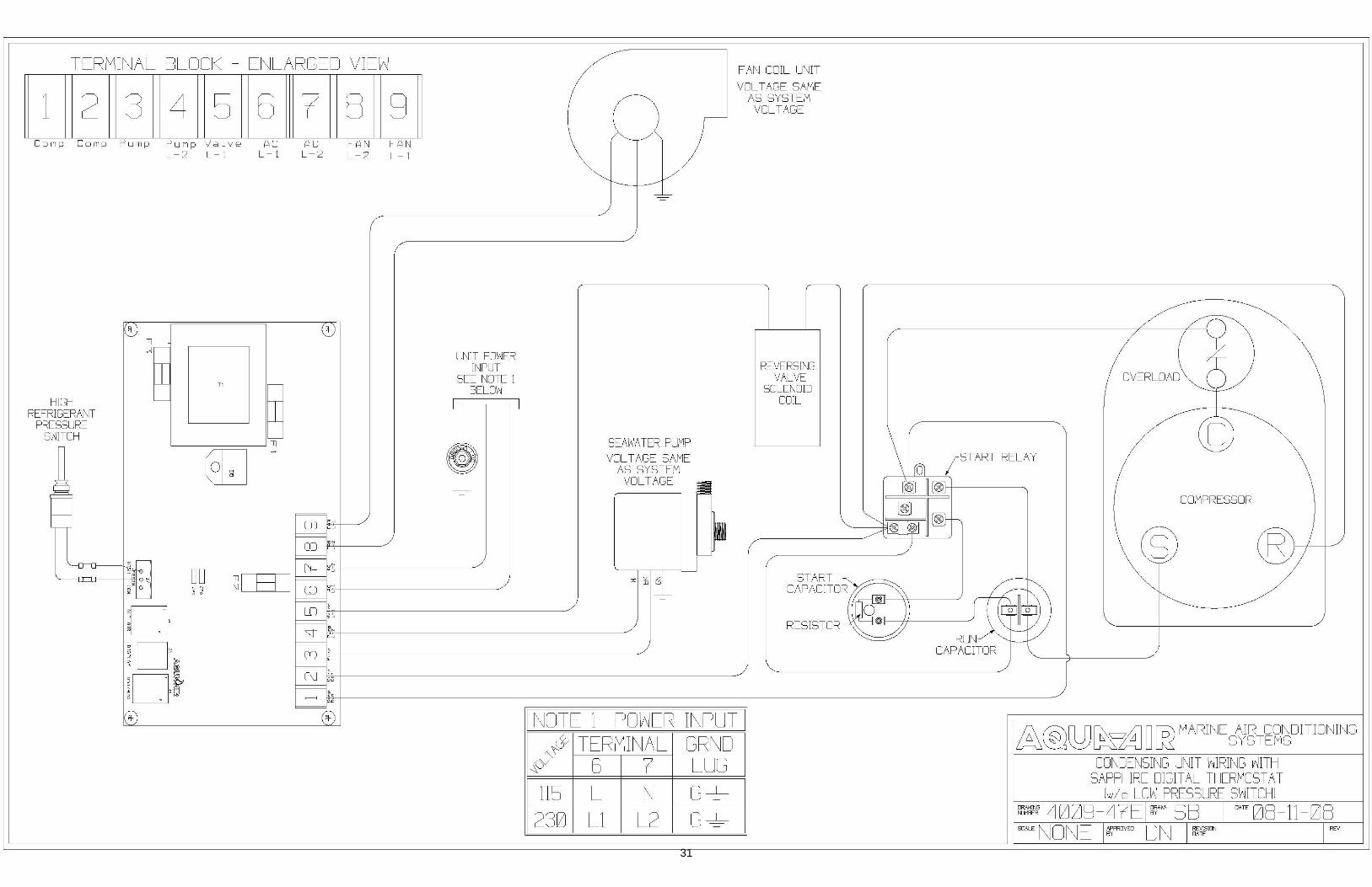
TERMINAL BLOCK - ENLARGED VIEW
III 112113114115116111711811 ~ I Comp Camp Pump Pump Valve AC AC FAN FAN
HIGH REFRIGERANT
PRESSURE SWITCH
L-2 L-j L-j L-2 L-2 L-j
UNIT POWER INPUT
SEE NOTE 1 BELOW
o
DO ~I H I CD ~---------" o
-
cO· . . , .
5EAHA TER PUMP VOL T AGE SAME
AS SYSTEM VOLTAGE
F AN COIL UNIT
VOL T AGE SAME AS SYSTEM VOLTAGE
REVERSING VALVE
SOLENOID COIL
\ rEi ART RELAY
~ I~
START ~
CAPACITOR! !/~~II-'\:--'I'I-_-----" / £T~ ~1J9: I) J II 0 IIII c I I
RESISTOR ~ RUN~~Y CAPACITOR
COMPRESSOR
:B~ ~ fr"r----------------------------------J
® ~ I NOTE 1 POWER INPUT I
~-{J<V TERMINAL GRND ~vv 6 7' LUG
ll5 L N 230 Ll L2
& @00 ~=~ ~ [}J2 MARINE Sy~T~g~DITIONING
CONDENSING UNIT NIRING NITH SAPPHIRE DIGITAL THERMOSTAT
[wi 0 LOW PRESSURE SNITCH I =':' 4009-4 lEI i'J'''' 58 I om 06-11-06 SVLE NON E ~VED 0 N I ~¥~Irn j REV
31

32

33


