SANTINO LT 5.0 OF PCT · Maintenance or repair on the open device may only be carried out by...
31
SOLUTIONS THAT COMPLETE! SOLUTIONS THAT COMPLETE! Product Manual SANTINO LT 5.0 OF PCT ARM Cortex A9 Rear Mount
Transcript of SANTINO LT 5.0 OF PCT · Maintenance or repair on the open device may only be carried out by...

SOLUTIONS THAT COMPLETE!SOLUTIONS THAT COMPLETE!
Product Manual
SANTINO LT 5.0 OF PCTARM Cortex A9 Rear Mount

2
PRODUCT MANUAL
SANTINO LT
Document Revision History
The information in this document is subject to change without prior notice in order to improve reliability, design and function and does not represent a commitment on the part of the manufacturer.
Online support on www.garz-fricke.com
Revision Date Author Description
V 1 14.09.2017 CG changes due to mechanical parts
V 2 13.03.2018 CG Capitel 6.10 Keypad change name of Pin 9+10
V 3 10.09.2019 CG Change address

PRODUCT MANUAL
SANTINO LT
Table of Contents
1. Introduction ....................................................................................... 42. Safety Hints........................................................................................ 53. Product Introduction ......................................................................... 63.1 Type Plate and Device Information ..........................................................63.2 Product names and variants ...................................................................73.3 Related Documents and Online Support .................................................84. Technical Data .................................................................................... 94.1 Block Diagram SBC .................................................................................114.2 Connectors ..............................................................................................125. Installation and Start Up .................................................................... 145.1 Connection Scheme .................................................................................146. Internal and External Interfaces ........................................................ 156.1 Speaker (X9) .............................................................................................156.2 Ethernet (X104) ........................................................................................156.3 Power (X1) ................................................................................................166.4 eBus (X108)* ............................................................................................166.5 RS-232/RS-485/CAN (X39) ......................................................................176.6 USB Host (X34) .........................................................................................186.7 USB OTG (X20) .........................................................................................186.8 Micro SD-Card Holder (X31) ....................................................................186.9 Battery Connector (X113) ........................................................................196.10 Keypad / I2C (X110) ...................................................................................207. Battery ............................................................................................... 217.1 Battery Specifications..............................................................................217.2 Replacement of the Internal Battery ......................................................22Annex A: Technical Drawing.............................................................................. 23Annex B: Hardware Revision Information ......................................................... 24Annex C: Assembly Options .............................................................................. 25C-1 Wi-Fi / Bluetooth .....................................................................................25Annex D: Guidelines and Standards ................................................................. 26D-1 RoHS Declaration ....................................................................................26D-2 Supplier Declaration – Directive EG 1907/2006 REACH .........................26D-3 UL Certification ........................................................................................26D-4 Garz & Fricke Conformity Statement ......................................................27Annex E: Common Documentation .................................................................... 28E-1 Warranty Hints .........................................................................................28E-2 Field of Application ..................................................................................29Annex F: Technical Support ............................................................................. 30Annex G: General Information .......................................................................... 31
* alternative assembly upon request

4
PRODUCT MANUAL
SANTINO LT
1. IntroductionThank you very much for purchasing a Garz & Fricke product. Our products are dedicated to professional use and therefore we suppose extended technical knowledge and practice in working with such products.
The information in this manual is subject to technical changes, particularly as a result of continuous product upgrades. Thus this manual only reflects the technical status of the products at the time of printing. Before design-in the device into your or your customer’s product, please verify that this document and the therein described specification is the latest revision and matches to the PCB version. We highly recommend contacting our technical sales team prior to any activity of that kind.
The attached documentation does not entail any guarantee on the part of Garz & Fricke GmbH with respect to technical processes described in the manual or any product characteristics set out in the manual. We do not accept any liability for any printing errors or other inaccuracies in the manual unless it can be proven that we are aware of such errors or inaccuracies or that we are unaware of these as a result of gross negligence and Garz & Fricke has failed to eliminate these errors or inaccuracies for this reason. Garz & Fricke GmbH expressly informs that this manual only contains a general description of technical processes and instructions which may not be applicable in every individual case. In cases of doubt, please contact our technical sales team.
In no event, Garz & Fricke is liable for any direct, indirect, special, incidental or consequential damages arising out of use or resulting from non-compliancy of therein conditions and precautions, even if advised of the possibility of such damages.
Before using a device covered by this document, please carefully read
Annex „E-1 Warranty Hints“ Annex „E-2 Field of Application“
Embedded systems are complex and sensitive electronic products. Please act carefully and ensure that only qualified personnel will handle and use the device at the stage of development. In the event of damage to the device caused by failure to observe the hints in this manual and on the device (especially the safety instructions), Garz & Fricke shall not be required to honour the warranty even during the warranty period and shall be exempted from the statutory accident liability obligation. Attempting to repair or modify the product also voids all warranty claims.

5
PRODUCT MANUAL
SANTINO LT
I. General Handling Don’t drop or strike the unit: The PCB, display and/or other parts might be damaged. Keep away from water and other liquids, the unit is not protected against. Operate the unit under electrical and environmental conditions according to the technical
specification. The electrical installations in the room must correspond to the requirements of the local
(country-specific) regulations. Take care that there are no cables, particularly power cables, in areas where persons can trip
over them. Do not place the device in direct sunlight, near heat sources or in a damp place. All plugs on the connection cables must be screwed or locked to the housing. Repairs may only be carried out by qualified specialist personnel authorized by
Garz & Fricke GmbH or their local distributors. Maintenance or repair on the open device may only be carried out by qualified personnel
authorized by Garz & Fricke GmbH which is aware of with the associated dangers.
II. Electricity The embedded systems may only be opened in accordance with the description in this user’s
manual for - replacing of the (rechargeable, where applicable) lithium battery and/or - configuration of interfaces, where applicable
These procedures have to be carried-out only by qualified specialist personnel. When accessing internal components the device must be switched off and disconnected from
the power source. When purchased core or basic versions without protecting back cover, don’t touch the PCB
directly with your fingers. Especially these products need to be handled very carefully. Don’t operate or handle the unit without typical ESD protection measures, such as ground
earthing. Operate the unit according to the technical specification only.
III. Damage or Permanent Malfunction It must be assumed that a safe operation is no longer possible, in case
-the device has visible damage or -the display is dark or shows strange pattern for longer period -the device doesn’t react after a reset
In these cases the device must be shut down and secured against further use
IV. LCD and touch handling If equipped with, the soft surface of a resistive touch screen is not suitable for use with
stencils and/or other devices for touch operation. There are special plastics pens available in commercial shops. A projective capacitive touch screen might be protected by a heat strengthened glass or acrylic or polycarbonate cover lens. These are dedicated for use with finger tips. There are very special pens available which might work with a PCT touch.
Protect the LCD/touch/cover lens against scratches and sharp edges. The warranty does not cover pixel failures resulting from non-compliant handling.
Clean the LCD/touch/cover lens with a soft cotton cloth with alcohol. Don’t use organic solvents, acid or alkali solutions.
Water drops, finger fat or any similar fouling should be removed immediately from the LCD, cover lens and metal frame to avoid any staining.
2. Safety HintsPlease read this section carefully and observe the instructions for your own safety and correct use of the device. Observe the warnings and instructions on the device and in the manual. Garz & Fricke embedded systems have been built and tested by us and left the company in a perfectly safe condition.In order to maintain this condition and ensure safe operation, the user must observe the instructions and warnings contained in this manual.
6
S/N: YY-WW
Made in Germany
25,4
50,5
Art.No.: 900-0000RModel: SANTINO LT x1
9-32 V ; 2,3-0,65 A
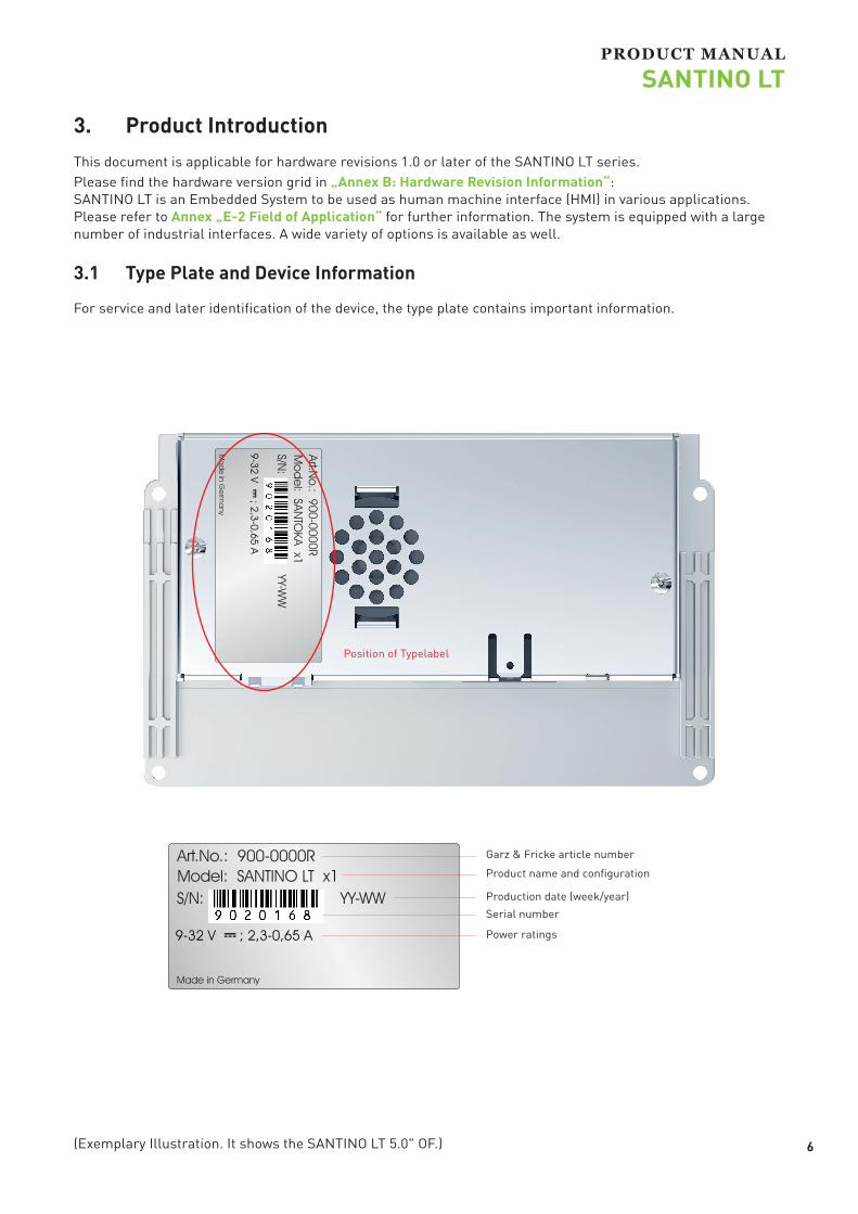
(Exemplary Illustration. It shows the SANTINO LT 5.0" OF.)
S/N:
YY-W
W
Ma
de
in Ge
rma
ny
25,4 50,5
Art.No.: 900-0000R
Mo
de
l: SANTO
KA x1
9-32 V ; 2,3-0,65 A
Position of Typelabel
PRODUCT MANUAL
SANTINO LT
3. Product Introduction This document is applicable for hardware revisions 1.0 or later of the SANTINO LT series. Please find the hardware version grid in „Annex B: Hardware Revision Information“: SANTINO LT is an Embedded System to be used as human machine interface (HMI) in various applications. Please refer to Annex „E-2 Field of Application“ for further information. The system is equipped with a large number of industrial interfaces. A wide variety of options is available as well.
3.1 Type Plate and Device Information
For service and later identification of the device, the type plate contains important information.
Garz & Fricke article number
Product name and configuration
Serial number
Power ratings
Production date (week/year)

7
PRODUCT MANUAL
SANTINO LT
3.2 Product names and variants
Product name definition:
SANTINO LT <CPU> <5.0> <OF> <PCT> <IPS> <additional description> <Vx.y.z>
Explanation:
SANTINO LT Product family name (invariable)
<CPU> x1, x2L (number of cores inside the i.MX6 processor)
<5.0> Display size in inch
<OF>, <SG>, <BX> mechanical design of enclosure
<PCT>, <RES> projected capacitive touch; if blank: 4-wire resistive
<IPS> Display technology “in-plane switching”, (option)
<additional description> contains variants which are important to sales product description, i.e.
without or with WLAN/Bluetooth module (“W/B”) untreated glass surface or including antiglare treatment (“AG”) front frame made from die-cast zinc or aluminium (“Alu”) different memory capacities for RAM and/or eMMC customer-specific reduced assembly etc.
<Vx.y.z> revision of PCB layout
<x> describes major changes in form fit and functions
<y> describes variants that are different in PCB layout and could affect the list of critical components (UL LoCC).
<z> describes minor changes to PCB layout due to production optimization like solder resist mask or drilling diameters. Also minor changes in assembly of PCB and/or device which do NOT affect the list of critical components (UL LoCC) due to unlisted components or declared “interchangeable”.

Flash-N-Go
http://mx31.de/k
Contains information about the usage of the G&F Flash-N-Go solution which consists of three submodules:
Flash-N-Go Boot (A tiny boot loader)Flash-N-Go System (A maintenance os)Flash-N-Go Update (A GUI based update solution for all os)
Linux Yocto Jethro
http://mx31.de/j
Contains information about Linux BSP with development environment Linux Embedded System Yocto (Codename: Jethro, Version 3.0) includes first information about the bootloader Flash-N-Go
8
PRODUCT MANUAL
SANTINO LT
3.3 Related Documents and Online Support
This document contains operating system specific information. The following additional documentations are available:
OPERATING SYSTEMS
UPDATE / BOOT / SYSTEM

CPU x1 x2L CPU Type i.MX6Solo i.MX6DualLite
Core Class ARM Cortex - A9
Core Clock 1 GHz
FeaturesNEON for SIMD media acceleration and VFP operations; Multi-format HD 1080p video decoder and HD 720p video encoder hardware engine; L1 cache, 32 KB for instruction, 32 KB for data; 512 KB L2 cache
HW Accelerators OpenGL ES 2.0, OpenVG 1.1
RTC Accuracy: +/- 30 ppm at 25°C
MemoryeMMC Flash 4 GB MLC eMMC
RAM Standard 512 MB 32 bit DDR3L 1 GB 32 bit DDR3L
MicroSD Card Slot 4 bit MMC/SDIO/SD/SDHC
Operating SystemsSupported OS Linux Yocto Jethro / Windows CE 7/2013 on request
Communication Interfaces Network 1x 10/100 Mbit/s Ethernet (RJ-45)RS-485 1 x RS-485 (Half duplex)
RS-2321x RS-232 (RX/TX/CTS/RTS)MDB 2 /1x MDB (Master / Slave optional) 3 instead of external RS-232
Synchronous Serial Interfaces
I²C, Matrix keypad up to 4 x 4
USB 2.01x 480 Mbit/s Host (Type A) 1x 480 Mbit/s OTG (Type Micro-AB) 1
CAN Fieldbus 1x CAN (ISO/DIS 11898)
AudioSpeaker output 1x speaker (connector), 1.5 W RMS (8Ω)Audio Internal 1x speaker 1 WRMS (8Ω) parallel to external outputDisplay and TouchSize 5.0 inch/ 125.95 mm
Resolution 800 x 480 pixel
Brightness up to 1120 cd/m²; software default: 400 cd/m²
Backlight Lifetime min. 50 000 h
Viewing Angle 60°, 70°, 75°, 75° (UDRL)
Color 24 bit (16.7 Mio. colors)
Touch projected capacitive multi touch
9
PRODUCT MANUAL
SANTINO LT
4. Technical Data
1 Mechanically the Micro-USB interface has not been designed for frequent contact operations. Please use an adapter cable with a strain relief. 2 Option 3 The selection of a variant eliminates the other.

Housing x1 x2L
* with a typical usage of GPU/CPU.
Usecase
Brightness: default (176)2x memtester 32M 1000000 &Qt5_CinematicExperienceUsage of Ethernet and RS232
Operating Temp: 0 to 45 °C
Brightness: maximum (255)2x memtester 32M 1000000Qt5_CinematicExperienceUsage of Ethernet and RS232
Operating Temp: 0 to 40 °C
Brightness: default (176)Usage of all interfacesqt-guf-demoCPU usage: ~45%
Operating Temp: 0 to 55 °C
1 0
PRODUCT MANUAL
SANTINO LT
Front 2.8 mm toughened glass; RAL 9005
Frame None
Rear Aluminum/ 1.4016 stainless steelIngress Protection Front IP 20/Rear IP20
Device DimensionsW x H x D 134.2 x 83.5 x 33.9 mm
Weight tbd.
Power SupplySupply Voltage Nom. 9 to 32 V DC
Consumption Typ. 7.1 W; max. 20.4 W
Internal Backup Battery (RTC)Type: 3 V Li-Ion Type CR1220: Lifetime (RTC only): Approximately 8 years, depending on application
Typical Environmental ConditionsStorage Temp. -20 to +70 °C
Operating Temp. 0 to +55 °C *
Humidity 5 to 90 % RH
Max. Operating Altitude ty 3.000 m
Max. Storage/Transit Altitude 10.000 m
Noise Level [db(A)] @ 1m <<40 (fanless design)
LifetimeMTBF ≥ 400.000 h (without backlight)

2x Speaker2-pole JST
RJ-45Jack
Audio Amplifier
EthernetPhy
USBType A
Block Diagram SANTINO LT
i.MX6
Keypad10-pole JST
USB-OTGMicro-AB
Micro-SD-CardConnector
I2C-3
USB H1
USDHC4
DRAM
eMMC
DDR3L
Audio Codec
FlexCAN-1
UART-1
GPIO
AUD4
MDIO/RMII
Res.Touch4-pole FFC
SD2
RS-23214-pole Molex
CAN Transceiver
RS-485Transceiver
RGB
PWM1
5V Supply
USB OTG
UART-2
TouchscreenController
Cap.Touch6-pole FFC
Backlight Driver
Backlight2 pole JST
RS-232Transceiver
MDB(optional)
UART-5
1x RGB 888
Backlight40-pole FFC
Battery
RTC
BatteryCR1220
RC 1
24 V 2-pole Phoenix
Step Down Converter
PMIC Power
1 1
PRODUCT MANUAL
SANTINO LT
4.1 Block Diagram SBC

Pos. Description
1 Speaker (X9)
2 Ethernet (X104)
3 Power (X1)
4 eBus (X108) Option
5 CAN/RS-485 Interface (X39)
6 USB Host (X34)
7 USB OTG (X20)
8 Battery (X113)1 2
X1
CR12203V
X104
(Exemplary Illustration. It shows the fully equipped SANTINO LT Dualcore light 5.0" OF.)
PRODUCT MANUAL
SANTINO LT
4.2 Connectors
As this manual describes an open frame version, only the external interfaces will be mentioned in the following chapter.

Pos. Description
9 Reset Switch (SW1)
10 Bootselect Switch (SW2)1
11 Micro SD Card (X31)
12 Keypad / I2C (X110)
1 3
PRODUCT MANUAL
SANTINO LT
(Exemplary Illustration both sides)
1 For the function of this switch please refer in the future to the Flash N Go User Manual.
Pos. Description
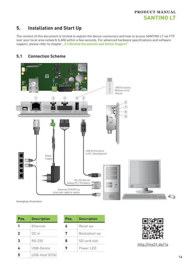
1 Ethernet
2 DC in
3 RS-232
4 USB-Device
5 USB-Host (OTG)
Pos. Description
6 Reset sw
7 Bootselect sw
8 SD card slot
9 Power LED
Exemplary Illustration
1 4
LAN Power USB-OTGUSB-HostRS232/RS485/CANSpeaker
Ethernet (TCP/IP) via cross over cable or switch
USB AccessoryMemory stick, mouse
RS-232 (Serial)Debug-PC / Periphery
Mic
ro S
D/S
DH
C
X1
CR12203V
X104
PowerSupply
USB (Active Sync)to PC / Development
PRODUCT MANUAL
SANTINO LT
5. Installation and Start UpThe content of this document is limited to explain the device connectors and how to access SANTINO LT via FTP over your local area network (LAN) within a few seconds. For advanced hardware specifications and software support, please refer to chapter „3.3 Related Documents and Online Support“
5.1 Connection Scheme
http://mx31.de/1a

Pin Name Description Information
1 Tx+
Rx/Tx might be swapped (Auto-MDIX) +/- might be swapped (Autom. polarity correction)
2 TX-
3 RX+
4SPARE 1
5
6 RX-
7SPARE 2
8
Header: RJ45
Pin Name Description Level
1 Speaker +Parallel to X10 1.5W RMS 8 Ohm
2 Speaker -
Header: JST S2B-PH-SM3-TBPlug: ST PHR-2 with crimp contacts SPH-002GW-P0.5L-ND
1 5
1
11
PRODUCT MANUAL
SANTINO LT
6. Internal and External Interfaces
6.1 Speaker (X9)
6.2 Ethernet (X104)
Green LED (link) is default off and turns on when link is detected.
Yellow LED (act) flashes during sending/receiving packets.

Pin Name Description Level
1 Vin+ Input voltage Nom. 9 to 32 V DC
2 Vin- Input voltage 0 V
Header: Phoenix Contact MC1,5/2-G-3,81 2pPlug: MCC 1/ 2-STZ-3,81 2p, crimp contact MCC-MT 0,5-1,0Shielding with 6,3 mm male spade terminal connector GND/Vcc_In is not galvanic isolated from System-GND
Pin Name Description Level
1 Vin + Input Voltage Nom. 9 to 32 V DC
2 eBus + eBus15 to 24 V High9 to 12 V Low
3 Vin - Input Voltage 0 V
4 GND Ground 0 V
Header: Phoenix Contact MCDN1,5/2-G1-3,81Plug: Phoenix Contact FMC 1,5/2-ST-3,81
1 6
1
PRODUCT MANUAL
SANTINO LT
6.3 Power (X1)
6.4 eBus (X108)*
instead of X1
* alternative assembly upon request
Caution: Power supplies connected to this device must be compliant to the requirements of “limited power sources” (LPS) to prevent the end-user from danger in case of a fault.

Pin Name Description Level
1 GND Ground
2 RS-232_TXD1 Port #1: Transmit data (Output) V. 28
3 RS-232_RXD1 Port #1: Receive data (Input) V. 28 +24 V
4 RS-232_RTS1 Port #1: Request-to-send (Output) V. 28 +24 V
5 RS-232_CTS1 Port #1: Clear-to-send (Input) V. 28
6 RS485_A_T+ RS485 Termination high side, bridge with T+
7 RS485_B_T- RS485 Termination low side, bridge with T-
8 GND Ground
9 CAN_H CAN bus high
10 CAN_L CAN bus low
11 CAN_TERM To enable CAN-Termination, bridge with CAN_L
12 GND Ground
RS485_T+ Half Duplex A
RS485_T- Half Duplex B
Header: Molex 43045-1400 Micro-Fit 14pPlug: Molex 43025-1400 Micro-Fit 14p, crimp contact Molex 43030-0007Shielding with 6.3 mm male spade terminal connector CAN/RS-485 is not galvanic isolated from System-GND/Housing
1 7
18
18
18
PRODUCT MANUAL
SANTINO LT
6.5 RS-232/RS-485/CAN (X39)
CAN1 Termination
RS485 Termination

Pin Name Description Level
1 USB_H1_VBUS Power supply +5 V DC max 500mA
2 USB_H1_DN Data minus (D-)
3 USB_H1_DP Data plus (D+)
4 GND Ground
Header: USB Type A
Pin Name Description Level
1 USB__OTG_VBUS Power supply +5 V DC max 500mA
2 USB_OTG_DN Data minus (D-)
3 USB_OTG_DP Data plus (D+)
4 USB-OTG_ID Device ID
5 GND Ground
Header: Micro-USB Type AB
Pin Name Description Level
1 DAT3
2 CMD Pullup 3.3 V
3 GND
4 VDD 3.3 V
5 CLK
6 GND
7 DAT0
8 DAT1
9 DAT2
1 8
1
1
PRODUCT MANUAL
SANTINO LT
6.6 USB Host (X34)
6.7 USB OTG (X20)
6.8 Micro SD-Card Holder (X31)

Pin Name Description Level1 VCC Supply 3 V
2 GND Ground
Header: Keystone 1056Battery: CR1220
+CR1220
3 V
1 9
PRODUCT MANUAL
SANTINO LT
6.9 Battery Connector (X113)

Pin Name DescriptionDefault Mode Level
1 Power Supply 5.0 V
2 GND Ground
3.3 V
3 PCK0_GPIO6_7 Keypad row 0
4 PCK1_GPIO6_8 Keypad column 0
5 PCK2_GPIO6_9 Keypad row 1
6 PCK3_GPIO6_10 Keypad column 1
7 PCK4_GPIO6_11 Keypad row 2
8 PCK5_GPIO6_15 Keypad column 2
9 I2C2_SDA I²C data
10 I2C2_SCL I²C clock
Header: JST DF20F-10DP, side entry, RM = 1.00 Plug: JST DF20-10DS-1C, crimp contact: DF20 F2830 SCF A
Drive Strength (Software defined) I_OL (mA) I_OH (mA)
Low 5.1 -5.1
Medium 10.2 -10,2
High 15.3 -15,3
2 0
12
PRODUCT MANUAL
SANTINO LT
6.10 Keypad / I2C (X110)
Keypad/SPI/I²C, multiplexed
Digital output Specification (3.3 V): V_OH: min OVDD-0.15; V_OL max: 0.15V

Type Garz & Fricke Article Number
Battery type CR1220 010-0059R
Manufacturer Model
Varta CR1220
Alpha 3 Manufacturing Ltd. YOBCR1220
Keystone 1220
Maxell CR1220
2 1
PRODUCT MANUAL
SANTINO LT
7. Battery
7.1 Battery Specifications
The internal baseboard is equipped with a Primary Lithium battery (type CR1220), which has a typical lifetime of 8 years.
Danger of explosion when replaced with wrong type of battery. Replace the battery only with a Lithium battery that has the same or equivalent type recommended by Garz & Fricke GmbH.
Do not dispose of used CMOS batteries in domestic waste. Dispose of the battery according to the local regulations dealing with the disposal of these special materials (e. g. to the collecting points for disposal of batteries).
One of these brands must be installed.
2 2
X1
CR12203V
X104
(Exemplary Illustration. It shows the SANTINO LT 5.0" OF.)
PRODUCT MANUAL
SANTINO LT
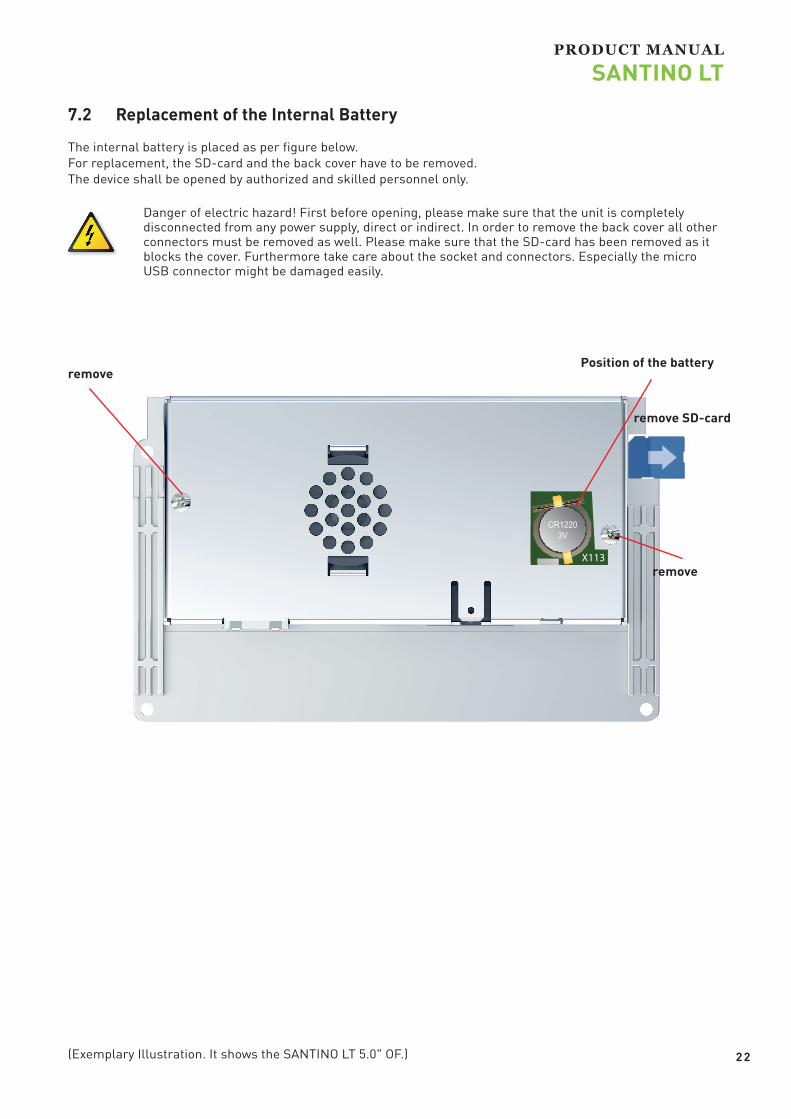
7.2 Replacement of the Internal Battery
The internal battery is placed as per figure below. For replacement, the SD-card and the back cover have to be removed. The device shall be opened by authorized and skilled personnel only.
Danger of electric hazard! First before opening, please make sure that the unit is completely disconnected from any power supply, direct or indirect. In order to remove the back cover all other connectors must be removed as well. Please make sure that the SD-card has been removed as it blocks the cover. Furthermore take care about the socket and connectors. Especially the micro USB connector might be damaged easily.
Position of the battery
remove
remove SD-card
remove

Annex A: Technical Drawing
108 (AA)
64,
80 (A
A)
119,72*
83,
01*
32,
80 ±
0,60
(c
ente
r AA
)
63,68 ±0,60 (center AA)
4x 3,50
18,55
11 07 10
09
08
31,
91
116,45 10,
36 3
3,88
01 02 03 04 05 06
57,
50
116,45 5,65
3,5
0
65,
60
21,
81
3,50 127,36
83,3
1(m
ount
ing
plat
e)
134,36(mounting
plate)
speaker/Lautsprecher
male spade terminal(Abschirmung/isolation)
depiction shows full equipment /Darstellung zeigt Vollausstattung
missing dimensions according to 3D data / Fehlende Maße bitte dem 3D Datensatz entnehmen
*front opening all aroundmin. 0.6 mm bigger/ /*Gehäuseausschnittumlaufend mind. 0,60 mmgrößer vorsehen!
center AA
Index Bezeichnung/designation01 USB-OTG02 USB-Host03 CAN/RS-485 Interface04 Power05 Ethernet06 Speaker07 SD-Card-Reader08 Status LED09 Clear all Switch10 Reset Switch11 Keypad
8 7
A
B
23456 1
578 246 13
E
D
C
F F
D
B
A
E
C
Schu
tzve
rmer
k ge
mäs
s IS
O 1
6016
Wei
terg
abe
sow
ie V
ervi
elfä
ltigu
ng d
iese
s D
okum
ents
, Ver
wer
tung
und
Mitt
eilu
ng s
eine
s In
halts
sin
d ve
rbot
en, s
owei
t nic
ht a
usdr
ückl
ich
gest
atte
t.Zu
wid
erha
ndlu
ngen
ver
pflic
hten
zu
Scha
dene
rsat
z. A
lle R
echt
e fü
r den
Fal
lde
r Pat
ent-,
Geb
rauc
hsm
uste
r- od
er G
esch
mac
ksm
uste
rein
tragu
ng v
orbe
halte
n.
Qualität
Produktion
Genehmigt
Geprüft
Bearbeitet
DatumSignaturName
entgraten und scharfe Kanten brechen
Wenn nicht anders definiert:Bemaßung in mm
© Garz & Fricke GmbH
(Masse)
24.08.2017Mues
SANTINO LT 5.0 OF PCT
1302DIN ISO
2768-mKDIN ISO
methodeProjektions- OberflächeToleranzangabe
Maße ohne
Ers. f.:
1 Bl.v.
1Blatt
900-xxxxR
1:2Maßstab:Werkstoff:

Hardware Revision Changes Marking on PCB
V1.0 initial release 0599 SANTINO LT V1.0
V1.1 Minor bug changes 0599 SANTINO LT V1.1
V1.1 Bug fix for audio codec 0599 SANTINO LT V1.1.1
2 4
PRODUCT MANUAL
SANTINO LT
Annex B: Hardware Revision InformationThis document is applicable for all products listed below. Please note that customized variants might possibly not support all features listed herein. Additional features are documented in specific attachments.
Platform Article Number Marking on PCB
SANTINO LT x1 5.0 OF PCT V1.1 900-3715R 0599 SANTINO LT V1.1.1
SANTINO LT x2L 5.0 OF PCT V1.1 900-3717R 0599 SANTINO LT V1.1.1

2 5
PRODUCT MANUAL
SANTINO LT
Annex C: Assembly Options
C-1 Wi-Fi / Bluetooth
Some appliances require a wireless network connection. To be more flexible with regard to future Wi-Fi standards and regulations, we decided not to assemble this functionality directly onto the single-board-computer. We recommend an external USB or miniPCIe solution. Drivers for both versions will be included in the related operating systems. Please contact the support for information about supported modules.

2 6
PRODUCT MANUAL
SANTINO LT
Annex D: Guidelines and Standards
D-1 RoHS Declaration
Devices comply with the requirements of Directive 2011/65/EU of the European Parliament and of the Council of 8th June 2011 on the restriction of the use of certain hazardous substances in electrical and electronic equipment.
D-2 Supplier Declaration – Directive EG 1907/2006 REACH
Garz & Fricke is manufacturer of electronic products, thus - in the sense of REACH - we are so called „downstream users“. The products we supply to you are solely non-chemical products (goods). Moreover and under normal and reasonably foreseeable circumstances of application, the goods supplied to you shall not release any substance. For that, Garz & Fricke is neither obligatory for registration nor for the creation of material safety data sheet (MSDS). From state of knowledge today our products contain no substances of very high concern from the current SVHC candidate list of the European Chemicals Agency in percentage >0,1. We will immediately inform you in correspondence to REACH-Article 33 if any substance of content >0,1 percentage in our goods will be classified alarming by the ECHA. Based on the current status, however, we do not expect such an incidence.
D-3 UL Certification
Customers of Garz & Fricke are attending on different markets. These markets are subjected to different UL certifications. Therefore Garz & Fricke have no UL certification for their products. To obtain UL certifications the product is designed to respect the following constraints:
All electronic printed circuit boards are conform to UL standard Battery schematics meets the requirements of UL standard (please refer to chapter
„6.9 Battery Connector (X113)“) All wirings are designed with UL components The selected components on the markets are UL (List of UL relevant components is available at
Garz & Fricke (on request))
Garz & Fricke do not guarantee to obtain UL certifications.

2 7
PRODUCT MANUAL
SANTINO LT
D-4 Garz & Fricke Conformity Statement
Garz & Fricke GmbH develops and distributes reliable, ARM-based embedded solutions. We offer various solutions from computer-on-modules (COM) to single-board computers (SBC) and fully-assembled human machine interface (HMI) with pre-installed operating system, display and housing.
These solutions are offered exclusively as OEM products. They do not include any application software that is intended for the end user. Therefore, we do not make any EU declarations of conformity in the name of Garz & Fricke GmbH and do not provide the products with the CE mark.
Our customers provide the products with application software and build them into an end-user device as part of an industrial production process. They identify themselves as a manufacturer by affixing a license plate with their company or brand name.
We are happy to assist our customers when they compile the necessary technical documentation for the EU Declaration of Conformity of the complete device. We provide e.g. Supplier declarations or RoHS certifications, issue EMC testing results and carry out safety / radio / SAR tests, etc.

2 8
PRODUCT MANUAL
SANTINO LT
[email protected]@garz-fricke.com
Annex E: Common Documentation
E-1 Warranty Hints
Garz & Fricke embedded systems are subject to manufacturer’s warranty as long as the products are handled with adequate care and caution and in accordance to this manual. The period of guarantee starts from the date of shipment The products are warranted against defects in material, quality and functionality within the warranty period. During this period, the repair of the products is free of charge. Garz & Fricke will decide for repair or replacement at their own discretion. If the product has been returned with or without prior notice and no failure or malfunction can be detected or the failure or malfunction is caused by inappropriate handling or the device has been returned after expiry of warranty period, Garz & Fricke reserve the right to charge the user for repair or replacement.
The warranty does not cover defects caused by improper or inadequate installation, maintenance or handling by the user, unauthorized modification or misuse, operation outside the specification a non-compliance of this manual. In case of doubt, please contact the technical sales team prior to intended activity. The warranty does also not cover any defects or damages of other equipment connected to the Garz & Fricke product, faulty or not. For warranty or repair service, please contact the technical sales team.

2 9
PRODUCT MANUAL
SANTINO LT
E-2 Field of Application
The products covered by this document are designed and manufactured for the following applications (I). If you intend to use these products in applications as quoted in (II) we highly recommend a personal contact with our consultants and/or technical sales team.
(I) Recommended application areas for Garz & Fricke embedded systems
Even for these applications, we recommend to get in contact with our technical sales team. We offer a wide range of support, even at an early stage of evaluation and/or design-in phase.
Vending machines and gastronomy devices Industrial controllers and HMI systems Home automation and facility management Audiovisual equipment Instrumentation and measuring equipment
(II) Restricted application areas, prior consultation is mandatory to identify and meet the individual regulatory requirements
Gas leak detectors Rescue and security equipment Safety devices Control and safety devices for airplanes, trains, automobiles and other transportation equipment Traffic control systems Control equipment for nuclear power industry Medical equipment related to life support etc. Gasoline stations and oil raffineries

3 0
PRODUCT MANUAL
SANTINO LT
Annex F: Technical Support Before contacting the Garz & Fricke support team, please try to help yourself by the means of this manual or any other documentation provided by Garz & Fricke or the related websites. If this does not help at all, please feel free to contact us. Our technicans and engineers will be glad to support you. Please note that beyond the support hours included the Starter Kit, various support packages are available. To keep the pure product cost at a reasonable level, we have to charge support and consulting services per effort.
Shipping Address:
Garz & Fricke GmbH
Schlachthofstraße 20
21079 Hamburg
Germany
Support Contact:
Phone: +49 (0) 40 / 791 899-200
Fax: +49 (0) 40 / 791 899-39
E-Mail: [email protected]
URL: www.garz-fricke.com

3 1
PRODUCT MANUAL
SANTINO LT
Annex G: General InformationTrademarks and service marks Names and logos in this document may be trademarks of their respective companies. In some cases descriptions for copyrighted products are not explicitly indicated as such. The absence of the trademark (™) and copyright (©) symbols does not imply that a product is not protected. Additionally, registered patents and trademarks are similarly not expressly indicated.
Drawings All drawings, which are shown in this manual are schematic drawings. For exact technical drawings please refer to our sales team or product manager All other product or service names are the property of their respective owners.
All rights reserved. Products subject to technical changes, improvements and misprints. © 2019 Garz & Fricke GmbH