Sans Digital‘s NAS User Guide Digital‘s NAS User Guide 9 Server Name: The name given to the NAS...
77
Sans Digital‘s NAS User Guide 1
Transcript of Sans Digital‘s NAS User Guide Digital‘s NAS User Guide 9 Server Name: The name given to the NAS...
Sans Digital‘s NAS User Guide 1

Sans Digital‘s NAS User Guide 2
Table of Contents
NAS GUI Menu Convention & Remarks ....................................................................................... 6
Chapter 1: Top-Menu-Entry: “System” ..................................................................................... 8
1.1 System General & Shutdown ...................................................................................... 8
1.2 System Admin Password ........................................................................................... 10
1.3 System UPS ............................................................................................................... 10
1.4 System Sensor ........................................................................................................... 11
1.5 System Update page .................................................................................................. 12
Chapter 2: Top-Menu-Entry: “Network”.................................................................................. 14
2.1 Network TCP/IP ........................................................................................................ 14
2.2 Network DNS ............................................................................................................ 16
2.3 Network Bonding (Teaming) .................................................................................... 17
2.4 Network Routing ....................................................................................................... 18
2.5 Network Host ............................................................................................................ 19
Chapter 3: Top-Menu-Entry: “Storage” ................................................................................... 21
3.1 What is “Model Dependent”? ........................................................................................ 21
3.2 Storage Internal RAID .............................................................................................. 22
3.3 Storage External RAID ............................................................................................. 23
3.4 Storage Software RAID ............................................................................................ 24
3.5 Basic Steps to Create a RAID ........................................................................................ 25
3.6 Storage iSCSI Initiator: ............................................................................................. 27
3.7 Storage USB/1394 page ............................................................................................. 28
3.8 Storage Volume Group page ..................................................................................... 29
3.9 Storage Logical Volume page ................................................................................... 30
3.10 How To Create Logical Volume (LV) Workflow .......................................................... 33
Chapter 4: Top-Menu-Entry: “Account” .................................................................................. 34
4.1 Account Local User page: ......................................................................................... 35
4.2 What is ‘Home’ (Home Directory / Home Folder)? ...................................................... 36
4.3 How to create and use ‘Home Folder’? .......................................................................... 37
4.4 Account Local Group ................................................................................................ 39
4.5 Account ADS ............................................................................................................ 41
4.5a Workgroup .................................................................................................................. 41
4.5b Domain. ...................................................................................................................... 41
4.5c ADS ............................................................................................................................ 42

Sans Digital‘s NAS User Guide 3
4.6d Joining ADS Server .................................................................................................... 43
4.5e ADS Option: ............................................................................................................... 43
4.6 Account NIS: ............................................................................................................. 44
4.7 Account LDAP page: ................................................................................................ 45
4.8 Account Quota: ......................................................................................................... 46
Chapter 5: Top-Menu-Entry: “Services” ...................................................................................... 48
5.1 Service SMB/CIFS page: .......................................................................................... 48
5.1a Advanced....................................................................................................................... 49
5.1b Shares ............................................................................................................................ 51
5.2 Service NFS ............................................................................................................... 54
5.2a Edit NFS Access Controls ............................................................................................. 54
5.3 Service AFP/Atalk ..................................................................................................... 56
The Apple Filing Protocol (AFP) ............................................................................................. 56
5.4 Service iSCSI Target page: iSCSI Target Service Management .............................. 58
5.5 Service Replication page: .......................................................................................... 60
5.5a Adding a new Replication Schedule ............................................................................. 61
5.6 Service Snapshot page ............................................................................................... 62
5.6a Adding new Snapshot Schedule .................................................................................... 62
5.7 Service Access Control page: .................................................................................... 63
5.7a Edit ................................................................................................................................ 63
5.8Tape Backup ........................................................................................................................ 64
5.9 Cloud Backup...................................................................................................................... 65
Chapter 6: Top-Menu-Entry: “Features” ...................................................................................... 67
6.1 Features FTP Service Management ........................................................................... 68
6.2 Features DHCP Management .................................................................................... 69
6.3 Features Network Time Service Management .......................................................... 70
6.4 Features UPNP .......................................................................................................... 70
6.5 Features DDNS Management .................................................................................... 71
6.6 Features Remote Access Management ...................................................................... 71
Chapter 7: Top-Menu-Entry: “Status” .......................................................................................... 72
7.1 Status Statistics .......................................................................................................... 73
7.2 Status Log .................................................................................................................. 74
7.3 Status User Access .................................................................................................... 75
7.4 Status Notification page: ........................................................................................... 75

Sans Digital‘s NAS User Guide 4
7.5 Status SNMP ............................................................................................................. 76
7.6 SMART (Disk & RAID) ..................................................................................................... 77

Sans Digital‘s NAS User Guide 5
Before reading on with this EliteNAS User Guide, first please familiarize yourself with the
following documents for quick and proper reference:
Default Admin ID: root --- case sensitive
Default Password: 0000 --- 4 zeros
“Quick Start Guide”
---- Instructions on how to quickly find the EliteNAS user’s network and set a static IP for the
NAS, then launch the Web Administrator GUI.
“Setup Workflow”
---- Illustrates quick steps for creating a SMB/CIFS share and how to access it from Windows
clients.
“Menu Layout”
---- Illustrates the GUI menu structure for navigating sub-menu items/actions branching out from
the top Menu-Entry.
“RAID Manager Guide”
--- Sans Digital’s NAS Hardware RAID models exclusively use either Areca’s SAS RAID
Adapter or LSI’s SAS RAID adapter. Hardware RAID adapters are very important parts of the
whole system, therefore we have created a dedicated user guide on proper setup and the RAID
volume management. Please refer to the proper RAID Manager Guide which comes with Sans
Digital’s EliteNAS.

Sans Digital‘s NAS User Guide 6
NAS GUI Menu Convention & Remarks
Note-#1: Top-Menu Entry & Sub-Menu List.

Sans Digital‘s NAS User Guide 7
Note-#2: Double-Display for Sub-Menu Quick Move-Around.
Each Top-Menu-Entry has multiple drop-down Sub-Menu entries.
When a Top-Menu-Entry is selected, the drop-down Sub-Menu will be displayed. At the same
time, the exact same Sub-Menu will also be displayed in the lower right corner for easy access
between sub-menu entries under the same Top-Menu-Entry.
Note-#3: Scroll Down to check more options. Always scroll all the way down the screen to see if there are any more options or an “Apply”
button.
Sans Digital‘s NAS User Guide 8
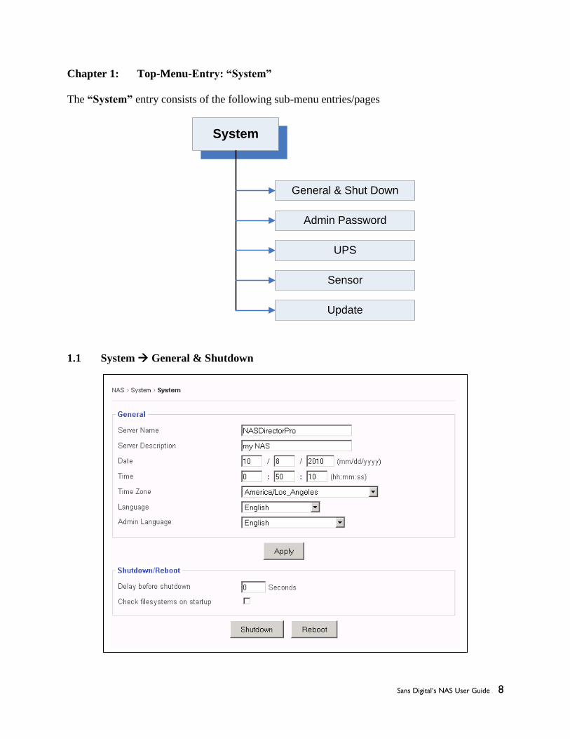
Chapter 1: Top-Menu-Entry: “System”
The “System” entry consists of the following sub-menu entries/pages
1.1 System General & Shutdown
System
General & Shut Down
Admin Password
UPS
Sensor
Update

Sans Digital‘s NAS User Guide 9
Server Name: The name given to the NAS unit, such as “MyCompanyNAS”, etc.
Server Description: Enter description to help identify usage of this unit. Example: “The
NAS backup for my SQL server,” etc.
Date / Time / Time Zone: Enter the current date and time zone of where this NAS is located
in.
Language: This setting determines what language the OS will display on the
network client.
Current supported languages include:
English (default)
Chinese Simplified
Chinese Traditional
UTF-8
Admin Language: This setting determines what language is displayed on the NAS Admin
GUI menu, accessed via web browser.
Currently, supported Admin Languages are:
English (default)
Simplified_Chinese_UTF8
Traditional_Chinese_BIG5
Traditional_Chinese_UTF8
Note: the setting for “Language” and “Admin Language” are two different settings. Generally, it
is advised that they should be set the same. Otherwise, the folder name or share name created by
NAS Admin GUI will not be the same as what is displayed on the network client.
Apply button: Click the “Apply” button to save any changes and put them into effect.
Shutdown button: Click to safely power off the NAS system.
Reboot button: Click to safely reboot the NAS system.
Delay before Shutdown: Desired number of seconds to wait before initiating the
shutdown process. By default, it is set to ‘0’ seconds.
Check Filesystems on Startup: This option will force the NAS OS to do a filesystem check
on each XFS volume (network share) every time it boots.
By default, this function is turned off.

Sans Digital‘s NAS User Guide 10
1.2 System Admin Password
This page is used to change the current admin password to a new password.
Current Password: Key in the current admin password.
New Password: Key in the new desired admin password
Confirm New Password: Re-key the new desired admin password to confirm.
Apply: Click the “Apply” to save change of password.
1.3 System UPS

Sans Digital‘s NAS User Guide 11
This page is to enable/disable UPS (un-interrupted power supply) Service, to manage some
UPS selections/settings.
Service Control Enable Service: Checking this option box will enable UPS service. By
default, this service is disabled.
UPS: This window lists the supported UPS brands and models. Scroll down to
find more brands and models.
Port: ‘port 1’ = COM1; ‘port2’ = COM2; ‘USB’ = USB port on the NAS
system. Select the proper Port Type according to what connectivity you
have between the NAS and your UPS.
Poll Frequency: This represents how often the system will check the UPS status. By
default, if the USP service is enabled, this is pre-set to 5 seconds.
Shutdown Delay: This represents how many seconds to wait before initiating the actual
shutdown after receiving the shutdown signal from UPS service. This is
pre-set set to 300 seconds.
Apply button: Click the “Apply” button to save the changes to the above fields.
Note: #1: No network UPS is supported, only support UPS is connected via RS232 or USB.
#2: For APC UPS, please use the “simple signal cable” for the RS232/COM port connection.
DO NOT use the “smart signal cable” which comes with the APC UPS by default.
1.4 System Sensor
Depends on the motherboard used in the NAS systems, this page may or may not display
anything.
There are two types of motherboard sensor implementations:
IPMI and None.
For None, the Sensor page will not display any info.
For IPMI, it will display readings for following sensors:
CPU1_Temp, CPU2_Temp, CPUx_Temp, etc.
System_Temp
CPU1_Vcore, CPU2_Vcore, CPUx_Vcore, etc.
CPU1_DIMM, CPU2_DIMM, CPUx_DIMM, etc.
+1.5V, +3.3V, +3.3VSB, +5V, +12V, VBAT, etc.
Fan1, Fan2, Fan3, Fan_x, etc.

Sans Digital‘s NAS User Guide 12
Pick the item(s) that you want the NAS to monitor and click “Save” button.
1.5 System Update page
This page is used for the following functions:
update patch
restore previous configuration
save existing system configuration
reboot the system after updating patch
enter new license to enable and reveal special Feature/Function
reset system configuration back to factory default.
Update:
Browse: Browse the admin’s local computer for the patch file.
No Dependency check: From time to time, some specific patches may require
check-marking this option in order for the new patch to be
installed.
Update button: Click “Update” to update the selected patch file. After
updating the patch, always reboot the system for the patch
to take effect.
Restore configuration:
Browse: Browse the admin’s local computer for selecting the previously
saved configuration file.
Restore configuration button:
This button will restore the selected previous-saved NAS
configuration back to the NAS. Reboot for the restored
configuration to take effect.

Sans Digital‘s NAS User Guide 13
Save configuration: This button is used to export the current NAS configuration into a
file and save it onto a local location on the administrator’s
computer. This file serves two purposes: (1) for future
configuration recovery purpose (2) email to technical support for
trouble-shooting.
Each time the administrator makes some changes, such as adding
users or deleting users, the configuration file needs to be re-saved
again. In other words, keep the saved configuration file up to date.
When clicking “Save configuration”, the GUI will prompt you to
browse and find a location in your computer to save the
configuration file.
Note:
The saved configuration does not include physical volume info because volume info is stored
and associated with the physical volume itself.
Reboot: Use the Reboot button to reboot each time after updating the
patch. Reboot each time after restoring the configuration file.
License: Use the License button to key in a new license for following
purposes:
increase/extend supported capacity
enable/reveal hidden functions/features
Reset configuration: This button is used to reset system configuration back to factory
default. It will remove all user accounts, either local or imported; it
will remove all LVs (logical volumes) and VGs (volume groups),
either network share volume or iSCSI volume, thus it will erase all
data.
It is useful for administrator who wants to start creating volumes
and users all over without worrying any potential hidden
corruption on the existing volume or unclear-flags on configuration
files.
Notes:
#1: Since it will erase all data in the NAS, please take extra precaution when using this function.
Please make sure either you have a full backup of the data in the NAS, or you are sure you don’t
need the data in the NAS any more.
#2: It will not reset the existing Network Configuration.

Sans Digital‘s NAS User Guide 14
Chapter 2: Top-Menu-Entry: “Network”
“Network” entry consists of the following sub-menu entries/pages:
2.1 Network TCP/IP
On this page, Static IPs can be set for specific NIC ports, along with some other properties.
Network
TCP/IP
DNS
Bonding
Routing
Hosts

Sans Digital‘s NAS User Guide 15
NIC Port is identified as “ethx”, such as: eth0, eth1, eth2, ……., etc.
When clicking the “Edit” button of a NIC Port (ethx), the corresponding configuration of the
selected NIC Port will display in the “Configuration” window.
Port: Displays which NIC Port is selected here.
Status: Shows if the port is Enabled or Disabled
Boot Protocol:
Static IP: Allows the admin to enter the static IP address, Netmask, and Default
Gateway for the NIC port.
DHCP: When selected, the NIC port will get an IP assigned from the DHCP server
in the network. The fields: IP address, Netmask, and Default Gateway
will display what values were assigned from the DHCP server.
Click “Apply” button to take effect of the settings
Boot Protocol:
Get Hostname from DHCP: If the Admin has the “reverse look up” enabled and
setups in the DHCP Server, then the DHCP server
will not only assign an IP to the NIC port, but will
also assign a Server Name to the NAS system. The
Server Name is the name defined in the “System
“General” page. This option is seldom used.
MTU: Maximum Transmission Unit. The default value is 1500. To enable Jumbo Frame,
refer to the actual Ethernet card being used for the proper MTU number. Most of
the Ethernet cards have 9000 MTU for Jumbo Frame, but other values besides
9000 exist for MTU.
Note: In order to use Jumbo Frame properly, the network switch and the other end of the device
accessing the NAS also need to be Jumbo Frame enabled and set to the same MTU. Otherwise,
unpredictable results may occur.
Apply button: Click to save changes and put into effect new settings. Upon clicking the
“Apply” button, this message will appear:

Sans Digital‘s NAS User Guide 16
The GUI will return after the displayed number of seconds
Blink button: This feature is used to help identify NIC ports. Upon clicking this button,
the physical LED on the selected NIC port will flash. This helps the user
identify the physical port for each NIC port.
2.2 Network DNS
DNS - Domain Name System (DNS) is a database system that translates a computer's fully
qualified domain name into an IP address. The computer system that runs the DNS functions is
called the DNS Server.
In a small network environment, such as a home network or small office network, the DNS could
be an internet Router. For bigger companies or corporations, normally there is at least one
dedicated DNS server in place.
Sans Digital’s NAS implements a “multi DNS” support scheme.
If the user has more than one DNS servers, up to 3 DNS Servers’ IPs can be listed, and if the
Primary DNS fails, the NAS will fall back to the Secondary DNS, and if the Second DNS fails,
too, then the NAS will fall back to the Tertiary (3rd) DNS.
Primary DNS / Secondary DNS / Tertiary DNS field:
Key in the IP address of the corresponding DNS Server.
If there is no Secondary or Tertiary DNS, leave the field blank.
DNS Search Path -- a DNS search path is a list of Domains to try/search for when the NAS
tries to translate a machine name into an IP address.
It is in the Format of: mycompany.com mycompany.net mycompany.org

Sans Digital‘s NAS User Guide 17
For small network environment, this does not apply, just simply “localdomain” will do.
Click “Apply” button save settings
2.3 Network Bonding (Teaming)
Bonding is sometimes referred to as Teaming. Its purpose is to bond multiple NIC ports
together under the same IP to increase bandwidth and/or provide path redundancy.
Bond Type: The Sans Digital’s NAS supports all 7 basic modes of bonding. However, in these
days only 2 types are commonly used, ALB and 802.3ad.
Bond Type ALB: Adaptive-Load-Balancing.
This attempts to redistribute network traffic (outgoing and incoming) quickly
based on current conditions. All NIC ports need to hook to the same network
switch, and the network switch needs to have special settings for it as long as the
switch is a true switch, not a hub. Because of that, the ALB mode is the most

Sans Digital‘s NAS User Guide 18
commonly used setting for the bonding, which is why we made it the default
setting for bonding. Besides increasing network performance, ALB also provides
network path failover in case of NIC port failure.
Notes on ALB:
#1: ALB does not increase Point-to-Point network performance. The performance
advantage only shows when there are multiple network clients accessing the NAS. In
addition, the performance increased is non-linear, so none of the bonding types will actually
provide a linear performance increase.
#2: All NIC Ports in the same bonding must hook to the same network switch. They
cannot be connected to different switches.
Bond Type 802.3ad:
Dynamic Link Aggregation. This creates aggregation groups that share the
same speed and duplex settings.
There are two types of 802.3ad: with or without LACP.
LACP stands for Link Aggregation Control Protocol. The Sans Digital’s
NAS supports ONLY the 802.3ad with LACP.
This mode requires a switch that supports IEEE 802.3ad with LACP, and
the switch needs to be configured on the specific ports that the NIC ports
are connected to.
Setting the Bonding: Select the NIC Ports intended to be bonded together and then click
the “Create” button to create the bonding.
Rules for Bonding:
The IP of the bond is always the first NIC Port in the Bond.
For example, in the above Bonding page screen, bonding the eth0 and eth1 will result in
the bond0 with eth0’s IP address: bond0 IP = eth0 IP = 192.168.2.21
Multiple bonds are supported, as long as each bond is on a different network.
For example: bond0 = 192.168.1.100 and bond1 = 192.168.2.100 are a valid setting.
However: bond0 = 192.168.1.100 and bond1 = 192.168.1.200 are not a valid setting.
2.4 Network Routing

Sans Digital‘s NAS User Guide 19
This function/page is dedicated for those sophisticated users who have had multiple
networks and gateways in their network environments. For those who don’t have multiple
networks/gateways, please disregard.
What is the “Routing” page” for?
Each NAS has at least two NICs, and some times more than two NICs. Some corporation users
have multiple subnets and need to assign each NIC with its own subnet and with its own
Gateway. However, under the “TCP/IP Setting” page, there is only one option field for “Default
Gateway”.
The “Routing” page is used to address this need by allowing additional Gateway IP and
Destination IP to be associated with designated NIC port.
2.5 Network Host

Sans Digital‘s NAS User Guide 20
The “Host” function allows the association of a network client’s name with its IP and store it
locally within the NAS. When it comes to finding a network client’s name/ip resolution, the
NAS will first look it up locally according to this “Host” information, then, go to the DNS server.
It is typically useful to enter your ADS server’s info here if intent is to join the NAS System to
an existing ADS server.
Note: Do Not Delete the first two existing Entries. Just leave them alone.
Address: The IP address of the network client, such as: 192.168.2.100
Names: The name of the network client, it can in any of the following formats:
mycompany
mycompany.com
mycompany mycompany.com (multiple names with space in between)
Make sure to click “Add” button to save changes.

Sans Digital‘s NAS User Guide 21
Chapter 3: Top-Menu-Entry: “Storage”
The “Storage” entry consists of following sub-menu entries/pages:
3.1 What is “Model Dependent”?
Sans Digital’s NAS has 3 models: Hardware RAID, Gateway, and Built-in RAID.
Hardware RAID – The NAS has an internal PCIe based RAID controller, and the NAS self-
contains the disks for storage capacity. When NAS is purchased as “Hardware
RAID model”, the “Internal RAID” a sub-menu entry will display. Otherwise,
this sub-menu entry will not display.
Gateway – The NAS has no internal storage at all; rather it is only a Head unit that connects
to external RAID subsystems via Fibre or SAS connectivity for storage capacity.
The “clustering” solution requires the Gateway model to implement. When the
NAS is purchased as “Gateway” model, the “External RAID” sub-menu entry
will display, otherwise, it is hidden from the sub-menu.
Built-in RAID – The NAS has no internal hardware RAID controller, it uses the OS based
built-in RAID to do the RAID array over disks. When a NAS is purchased as
Built-in RAID model, the “Software RAID” sub-menu entry will display,
otherwise it is hidden.
Storage
Internal RAID (model dependent)
External RAID (model dependent)
Software RAID (model dependent)
USB / 1394
Volume Group
Logical Volume
iSCSI Initiator
Sans Digital‘s NAS User Guide 22
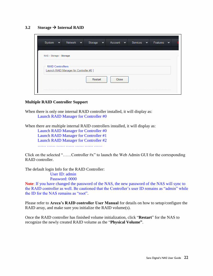
3.2 Storage Internal RAID
Multiple RAID Controller Support
When there is only one internal RAID controller installed, it will display as:
Launch RAID Manager for Controller #0
When there are multiple internal RAID controllers installed, it will display as:
Launch RAID Manager for Controller #0
Launch RAID Manager for Controller #1
Launch RAID Manager for Controller #2
…… …… …… …… …… …… ……
Click on the selected “……Controller #x” to launch the Web Admin GUI for the corresponding
RAID controller.
The default login Info for the RAID Controller:
User ID: admin
Password: 0000
Note: If you have changed the password of the NAS, the new password of the NAS will sync to
the RAID controller as well. Be cautioned that the Controller’s user ID remains as “admin” while
the ID for the NAS remains as “root”.
Please refer to Areca’s RAID controller User Manual for details on how to setup/configure the
RAID array, and make sure you initialize the RAID volume(s).
Once the RAID controller has finished volume initialization, click “Restart” for the NAS to
recognize the newly created RAID volume as the “Physical Volume”.

Sans Digital‘s NAS User Guide 23
3.3 Storage External RAID
The “External RAID” page will display only on the “Gateway/Head” model, otherwise this
function hidden.
This function is designed for the external RAID GUI management that uses Web based GUI with
IP address. If your external RAID GUI management is some sort of executable application
program other than Web browser, then it is not covered by this function.
Fill the URL field with IP address of the External RAID’s GUI
Fill the Description field with a description for the URL.
Then, click “Add.”
Now click on the “IP” of the “RAID Manager URLs.” Doing so will bring up the Web GUI
Management of your External RAID system.
Sans Digital‘s NAS User Guide 24
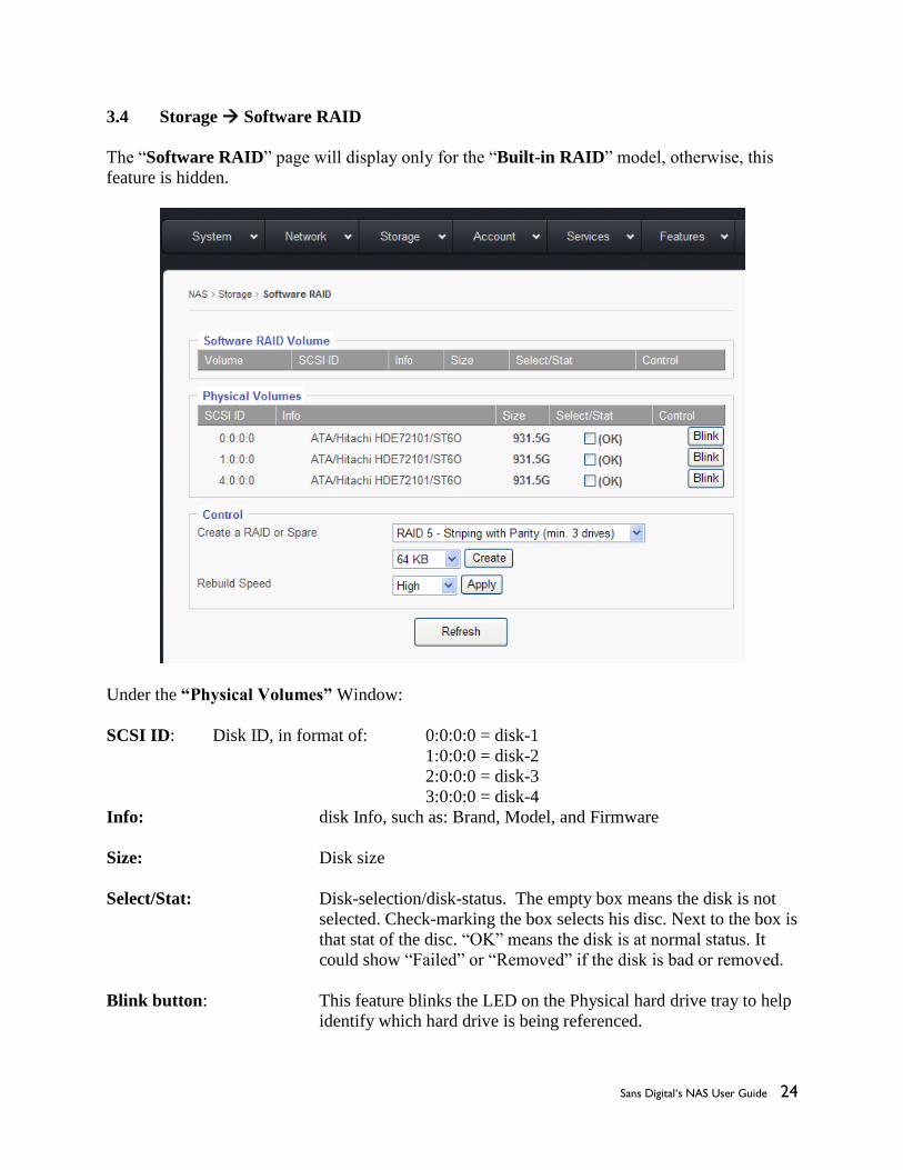
3.4 Storage Software RAID
The “Software RAID” page will display only for the “Built-in RAID” model, otherwise, this
feature is hidden.
Under the “Physical Volumes” Window:
SCSI ID: Disk ID, in format of: 0:0:0:0 = disk-1
1:0:0:0 = disk-2
2:0:0:0 = disk-3
3:0:0:0 = disk-4
Info: disk Info, such as: Brand, Model, and Firmware
Size: Disk size
Select/Stat: Disk-selection/disk-status. The empty box means the disk is not
selected. Check-marking the box selects his disc. Next to the box is
that stat of the disc. “OK” means the disk is at normal status. It
could show “Failed” or “Removed” if the disk is bad or removed.
Blink button: This feature blinks the LED on the Physical hard drive tray to help
identify which hard drive is being referenced.

Sans Digital‘s NAS User Guide 25
Create a RAID or Spare: When there are no existing RAID volumes, you can only create a
RAID and will not be allowed to create a Spare. The Spare is
allowed only if you have an existing RAID with RAID-level of: 1,
5, 6, or 10
Supported RAID-level is: 0, 1, 5, 6, or 10
Stripe Size: The stripe size for the RAID can be anywhere from 4KB ~
1024KB. Option is selected via the drop down menu. The default
size is 64KB
Rebuild Speed: The options are: High, Mid, and Low. This is used to define how
much internal storage speed should be allocated to the RAID
rebuilding, therefore, reserve a portion of resources for normal data
accessing. The higher the rebuild speed is, the less resources it has
for normal data access.
For first time RAID creations, always set rebuild speed to “High,”
to decrease time needed to initialize RAID.
3.5 Basic Steps to Create a RAID:
Step-1: select by check-marking all the disks to be put into the same RAID array.
Step-2: select the RAID-level
Step-3: select the Stripe-Size, or leave it at 64KB
Step-4: click the “Create” button, and the GUI will display the page below:

Sans Digital‘s NAS User Guide 26
Notice that the disks selected have disappeared from the “Physical Volumes” window, and have
shown up in the “Software RAID Volume” Window.
Now under the Software RAID Volume window, we have:
Volume: SW-RAID#0, if there are more than one SW-RAID, they will be, SW-RAID#1,
SW-RAID#2, so forth and so on.
Info: RAID-Level Info, such as RAID5, or RAID0, or RAID6, etc.
Select/Stat: RAID volume-selection/RAID volume-status. When the selection box is empty,
its means that the RAID is not selected.
Status can be: Normal, Degraded, Failed, Degraded recovering %, etc.
Remove button: Select by check-marking a RAID, and then if the “Remove” button is
clicked, the selected RAID volume will be removed/deleted.
Check button: Select by check-marking a RAID, and then if the “Check” button is
clicked, the selected RAID volume will run consistency check for RAID-
level: 5 or 6.
Create a HotSpare: If the existing RAID-level is 5, 6, or 10, a HotSpare disk can be added to it.
1. Select by check-marking a RAID volume from the Software RAID
Volume window.

Sans Digital‘s NAS User Guide 27
2. Select a disk from the Physical Volume window.
3. Click “Create.”
3.6 Storage iSCSI Initiator:
Sans Digital’s NAS has a built-in iSCSI initiator function which allows the administrator to pull
in a remote iSCSI Target volume as the local physical volume.
Basic Steps to connect to a remote iSCSI Target / LUN:
Step-1: Check-marking “Enable Service” option box
Step-2: Key in the remote iSCSI Target’s IP address in “iSCSI Target Discovery IP:”

Sans Digital‘s NAS User Guide 28
Step-3: Key in the remote iSCSI Target port number if it is not the default 3260.
Step-4: Click the “Discover” button. If the Target IP is correct, the Target name will show
up in the “Target List” window and the corresponding iSCSI LUN will show up in the
“iSCSI LUN Log In and Out” window.
Step-5: Select the iSCSI LUN and click “Log In.”
For CHAP, please refer to the remote iSCSI Target’s requirement.
3.7 Storage USB/1394 page
When an USB or 1394 disk is plugged into the system, a device and corresponding capacity will
be displayed in the “Raw USB/1394 Volume Pool” window.
Give it a name in the “Name” field and click “Import” and the format screen will appear.
Once it is formatted, it will show up in the “USB/1394 Volume Pool” and be ready to be used.
USB/1394 disk is intended to be removable, and removing a XFS volume while online can
disrupt the entire OS and all volumes. Therefore, the USB/1394 volume is defaulted to be
“FAT32,” which in turn limits the volume size to a 2TB maximum.
USB/1394 volume is a logical volume, therefore there is no need to go through the settings in the
“Volume Group” page and “Logical Volume” page.
Depending on the chip used in the motherboard/system and the chip used in the external Device,
sometimes they are not compatible, so in such a case the USB/1394 disk will not be supported.

Sans Digital‘s NAS User Guide 29
3.8 Storage Volume Group page
After the Internal RAID volume/External RAID volume/iSCSI Target volume has been
created and the NAS restarted, the volume will show up in the “Physical Volumes” window.
Check-mark to select the Physical Volume (aka PV), and click the “Create VG” button.
Now, the selected PV will turn into VG and display under the “Volume Group” window.
With multiple PVs, multiple VGs can be created.
To increase the size of an existing VG, just simply add a new PV to the existing VG by check-
marking both the PV and VG, and then clicking “Add PV to VG”.
Adding a PV to an existing VG is also called: Linear RAID or Spanning.

Sans Digital‘s NAS User Guide 30
3.9 Storage Logical Volume page
This is the last stop in creating the network volume or iSCSI Target volume.
Volume Types:
XFS – a XFS volume is to be created for network share(s).
“Assign Home Directory” is an option used to create a “home” folder for
each user on that network share. Regardless of how many XFS shares you
may have, only one XFS share can be used to create “home” folder.
GFS2 – a GFS2 volume is to be created for clustered network share(s), and only
shows when a special license is entered. Otherwise, it is hidden. The
special GFS2 license is only available for the Gateway/Head Model.
ISCSI – an iSCSI volume is used to create the iSCSI target volume, and it will act
as a local disk to the remote iSCSI initiator.
iSCSI target volume has an extra field: LUN#
By default, the LUN# = 0. However, if you are using multiple iSCSI target
volumes from multiple NAS units with VMWare ESX, then you might
need to adjust the LUN# on them so that no two iSCSI target volumes will
have the same LUN#. Otherwise, ESX will assign the exact same ID to all
the volumes and won’t connect properly.

Sans Digital‘s NAS User Guide 31
This is a typical illustration for how it looks like after a typical XFS share and an iSCSI
target volume are created.
VG0 – It has 714,272MB in size, it has two LVs created on it, and it has 414,272MB free
space for more LVs.
share0 – It is a XFS share from VG0, it has size of 200,000MB, which is all free.
ivolume – It is an iSCSI target volume from VG0, it has size of 100,000MB, and since
contents of an iSCSI volume is solely controlled by the iSCSI initiator, and the
NAS will not show the Free space of it.
XFS volume and/or iSCSI target volume can be deleted by clicking “Delete.”
But they can also be “Modified.” See next page for details.

Sans Digital‘s NAS User Guide 32
When clicking on an existing LV name, the “Modify Logical Volume” window will display the
corresponding LV info.
In the “Modify Logical Volume” window, you can do:
* Change the volume name – Enter the new volume name replacing
the old volume name.
* Increase the volume size – If the VG still has free/available space, then enter the new
larger size for the Volume Size.
Click “Modify” to save and apply changes or click “Back” to cancel.
In next page, we will review the process and workflow of creating LV.
Sans Digital‘s NAS User Guide 33
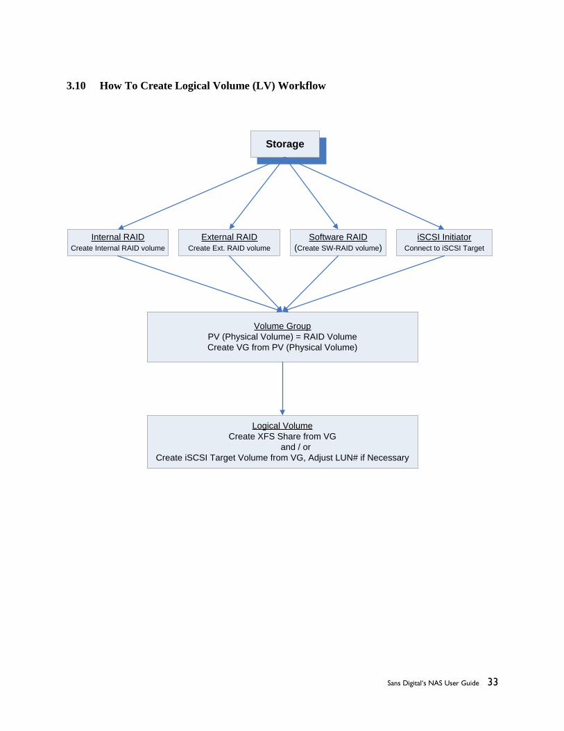
3.10 How To Create Logical Volume (LV) Workflow
Storage
Internal RAID
Create Internal RAID volume
External RAID
Create Ext. RAID volume
Software RAID
(Create SW-RAID volume)
Volume Group
PV (Physical Volume) = RAID Volume
Create VG from PV (Physical Volume)
Logical Volume
Create XFS Share from VG
and / or
Create iSCSI Target Volume from VG, Adjust LUN# if Necessary
iSCSI Initiator
Connect to iSCSI Target

Sans Digital‘s NAS User Guide 34
Chapter 4: Top-Menu-Entry: “Account”
“Account” entry consists of following sub-menu entries/pages:
Account entry is used to allow the administrator to do following functions:
Create local users and local groups
Join Windows Active Directory Service Server or PDC
Join NIS server for Unix/Linux NFS clients
Join LDAP server for Unix/Linux NFS clients ( LDAP for SMB/CIFS clients is
not supported)
Assign quotas to users and groups.
Account
Local User
Local Group
ADS
NIS
LDAP
Quota
Sans Digital‘s NAS User Guide 35
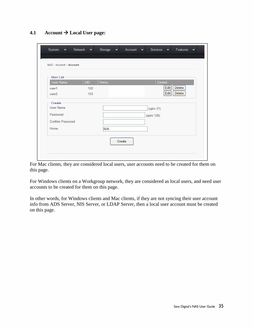
4.1 Account Local User page:
For Mac clients, they are considered local users, user accounts need to be created for them on
this page.
For Windows clients on a Workgroup network, they are considered as local users, and need user
accounts to be created for them on this page.
In other words, for Windows clients and Mac clients, if they are not syncing their user account
info from ADS Server, NIS Server, or LDAP Server, then a local user account must be created
on this page.
Sans Digital‘s NAS User Guide 36
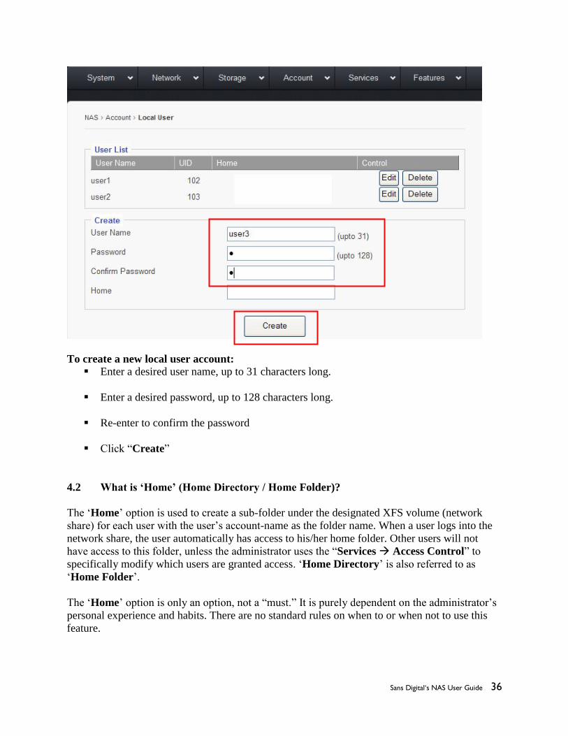
To create a new local user account:
Enter a desired user name, up to 31 characters long.
Enter a desired password, up to 128 characters long.
Re-enter to confirm the password
Click “Create”
4.2 What is ‘Home’ (Home Directory / Home Folder)?
The ‘Home’ option is used to create a sub-folder under the designated XFS volume (network
share) for each user with the user’s account-name as the folder name. When a user logs into the
network share, the user automatically has access to his/her home folder. Other users will not
have access to this folder, unless the administrator uses the “Services Access Control” to
specifically modify which users are granted access. ‘Home Directory’ is also referred to as
‘Home Folder’.
The ‘Home’ option is only an option, not a “must.” It is purely dependent on the administrator’s
personal experience and habits. There are no standard rules on when to or when not to use this
feature.

Sans Digital‘s NAS User Guide 37
Most of the NAS units in the data center do not use this option. But some IT staff found this
“Home” option to be handy and are very used to it.
4.3 How to create and use ‘Home Folder’?
There are two steps to creating the ‘Home Folder’, and one step to assigning access permissions.
Step-1: Enable the “Assign Home Directory” option for the selected XFS volume in the
“Storage Logical Volumes” page. See below.
Step-2: When creating a local user, the administrator is given an option to create the
‘Home’ folder on the previously selected volume with the default path. See
below:
X

Sans Digital‘s NAS User Guide 38
With the given example here: share0, user1, user2, and user3; it works like below.
Inside the share folder ‘share0’, there are the sub-folders: ‘user1’, ‘user2’, and ‘user3’; the
directory looks like this:
\\share0
\\share0\user1
\\share0\user2
\\share0\user3
When user1 logins to the share, user1 will see it like this:
\\home
\\share0
\\user1
In here, the “\\home” and “\\user1” and “\\share0\user1” are actually the same folder, it is
just being displayed by different names at different locations. The user1 will have the full access
permissions to them by default. If user1 navigates to \\share0, user1 will see all 3 sub-folders:
\\share0\user1, \\share0\user2, \\share0\user3; but only has access rights to the \user1 sub-folder.
The access rights for user1 to other user’s home folder can be granted by “Service Access
Control,” which will be discussed in a later section of this user guide.
When user2 logs into the share, user2 will see it like this:
\\home
\\share0
\\user2
In here, the “\\home” and “\\user2” and “\\share0\user2” are actually the same folder, it is
just being displayed by different names at different locations.

Sans Digital‘s NAS User Guide 39
Notice now “\\user1” has been replaced by “\\user2” when user2 logins.
Step-3: Assign user access permissions to the volume/share in the “Services
SMB/CIFS” page. Please refer to the Top-Menu Entry –Services section for
more details.
4.4 Account Local Group
Local Group is used to create a group(s) of local users, so that later on, the administrator can
simplify the process on assigning Access Rights for a group of users who share the same
permissions instead of individually assigning rights to each user one by one.
Creating Local Group:
Key the group name in the Local group name field, up to 31 characters long, without any spaces
in between, and then click the “Create” button.

Sans Digital‘s NAS User Guide 40
Adding Users to the Group.
Once the Group is created, the administrator can start adding users to it.
Select the Group by clicking the little round dot
Select the user name from the “All Users” window
Click “Add” to save changes.

Sans Digital‘s NAS User Guide 41
4.5 Account ADS
This section defines if the NAS will be in a stand-alone network (Workgroup), or if it will
join the Microsoft PDC server, or if it will join the Microsoft Active Directory Service
server.
4.5a Workgroup
If PDC or AD Servers are absent in your network or if you have PDC/AD Server in your
network but you don’t plan to join the NAS to the domain for domain users, and then just select
the “Workgroup” option.
Either leave the name “WORKGROUP” as it is, or you may change it to a desired name, then
click “Apply” to save the changes.
4.5b Domain.

Sans Digital‘s NAS User Guide 42
Domain is referring to the PDC created on a Windows NT or Windows 2000 Server.
If using a Windows Active Directory Service server, do not use the “Domain” option, instead
use the “ADS” option instead.
To join a PDC:
Enter the Domain Name
Enter the PDC’s IP address in the “Controller” field.
In the “Admin Account” field, enter the Administrator ID (it can be a User ID who has
the equivalent rights as the Administrator)
Enter the password for the Administrator on the PDC
Click “Apply”
4.5c ADS

Sans Digital‘s NAS User Guide 43
AD here is referring to the Microsoft Active Directory Service server. If using a PDC based on
Windows NT, then please do not use the “ADS” option, use the “Domain” option instead.
Prerequisites for Joining AD Server:
Time Syncing
The time on the NAS should be in-sync with the ADS server, meaning that the time on
the NAS should be set to the same time zone as the ADS server, and the time difference
should be less than 2 minutes apart. The time syncing can be achieved by setting the NAS
to a common NTP server (refer to Top-Menu-Entry: Features NTP)
DNS Server and Local Domain
Make sure to provide accurate DNS Server information and “DNS search path” (local
domain) in the Top-Menu-Entry: Network DNS page.
4.6d Joining ADS Server
Select “ADS” option
Realm Name: = Domain Name = MyCompany.com
Controller: IP address of the ADS server
Admin Count: the administrator’s ID, it is normally the “administrator”, but it could also be a
user ID who has the administrator rights.
Password: the password for the administrator on the ADS server.
4.5e ADS Option:
Controller (host name): Provides further detail info of the ADS server.
The “host name” here is the FQDN (Fully Qualified Domain
Name), such as: www.MyCompany.com
Enumerate User/Group: This option defines whether or not to sync users and groups on the
ADS server into the NAS.
When this option box is checked, the NAS will sync users and
groups from the ADS server to the NAS. Depending on the number
of users and groups, this syncing process might take anywhere from
a few minutes to a few hours. If there are too many ADS users and
groups, it becomes unpractical to do so, and the option should be
left un-checked.
When the ADS server has many users, normally they are divided
into a few groups and each group shares the same access
permissions characteristics. So even without importing the users
and groups to the NAS, the administrator can manually type in the
group names and assign access rights to them, plus a few
Sans Digital‘s NAS User Guide 44
exceptions on users. This step is done in the Top-Menu-Entry:
Service SMP/CIFS sub-menu.
There is no hard-coded standard for how many ADS users are too
many to use “Enumerate User/Group” option. Couple hundred ADS
users seems to be OK to enable it. Trial and error is the only way to
determine actual capacity.
Use Default Domain: To the NAS, ADS user ID is in the format of: ‘domain\user’. If
“User Default Domain” option is checked, then the user ID can be
referred to as ‘user’ without the ‘domain\’ in the later on session:
Top-Menu Entry: Service for ACL.
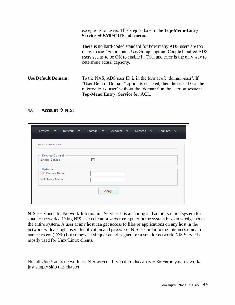
4.6 Account NIS:
NIS ---- stands for Network Information Service. It is a naming and administration system for
smaller networks. Using NIS, each client or server computer in the system has knowledge about
the entire system. A user at any host can get access to files or applications on any host in the
network with a single user identification and password. NIS is similar to the Internet's domain
name system (DNS) but somewhat simpler and designed for a smaller network. NIS Server is
mostly used for Unix/Linux clients.
Not all Unix/Linux network use NIS servers. If you don’t have a NIS Server in your network,
just simply skip this chapter.

Sans Digital‘s NAS User Guide 45
If you do have a NIS server and would like to use one for NAS authentication, then,
Enable the NIS service
Key in the NIS Domain Name
Key in the NIS Server Name
Click “Apply” button
4.7 Account LDAP page:
LDAP (Lightweight Directory Access Protocol) is a protocol used to access network directory
for user/client authentication.
Note: the LDAP service supported by our NAS system is for NFS clients only. LDAP service for
SMB/CIFS clients are not supported yet.
(NFS client = Unix / Linux clients; SMB/CIFS clients = Windows clients)
Enable Service – Check option box to enable LDAP service.
Server – Either IP or Name of the LDAP server
Base dn – It is the LDAP Domain name, if the Domain name is: mycompany.com

Sans Digital‘s NAS User Guide 46
then it is in the format of: dc=mycompany, dc=com
User suffix – Defined by the LDAP admin, used to get the user info from LDAP server.
Group suffix– Defined by the LDAP admin, used to get the group info from LDAP
server.
SSL – This displays if an encryption is being used
Bind den – Administrator ID of the LDAP domain.
Credential – Password of the admin ID on the LDAP domain.
Don’t forget to click the Apply button!
4.8 Account Quota:
Quota means to assign storage limits to users or group of users. Quota can be either by size
(MB – number of Megabytes) or by number of files.

Sans Digital‘s NAS User Guide 47
Logical Volumes: Pick the Logical Volume which you will assign quota for.
Enable Quota: Check-mark the option box to enable the Quota service.
Soft Limit with email notification: Enter the % for approaching Quota-Full warning.
When the used capacity has reached the
predefined % here, the system will automatically
send out an email notification to the administrator
for warning.
Fill numbers at once – this is used to fill every and all users or groups with the same number of
Megabytes or same number of files with one click-action, so that the administrator does not
need to assign quota user by user or group by group.
Enter the number of Megabytes in the field: Quota ______ MB
or enter the Number of files for each user/group, in the field: Number of files _______ EA
Click on ‘User’ to fill the quota to each/all users
or Click on “Group” to fill the quota to each/all groups
Sans Digital‘s NAS User Guide 48
If you are not using the Fill numbers at once, then you can manually enter the quota for each
user or group here.
Under the ‘Local Users’, all users are listed.
Under the ‘Local Groups’, all groups are listed.
Don’t forget to click “Apply” button.
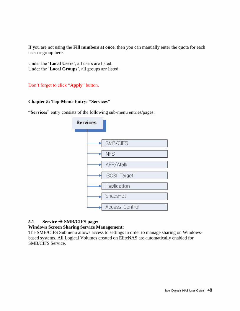
Chapter 5: Top-Menu-Entry: “Services”
“Services” entry consists of the following sub-menu entries/pages:
5.1 Service SMB/CIFS page:
Windows Screen Sharing Service Management:
The SMB/CIFS Submenu allows access to settings in order to manage sharing on Windows-
based systems. All Logical Volumes created on EliteNAS are automatically enabled for
SMB/CIFS Service.

Sans Digital‘s NAS User Guide 49
Service Control
Enable SMB/CIFS Service
1. Check “Enable SMB/CIFS Service” option box.
2. Click “Apply” to save changes.
Note: SMB/CIFS Service must be enabled for EliteNAS to share files on Windows-based
systems.
Disable SMB/CIFS Service
1. Uncheck “Enable SMB/CIFS Service” option box.
2. Click “Apply” to save changes
5.1a Advanced
The “Advanced” button brings up additional options.

Sans Digital‘s NAS User Guide 50
Advanced Options:
Recycle Bin
By checking this option box, the Recycle Bin function for SMB/CIFS client is enabled.
Keep Tree
This option specifies if a directory structure should be kept, or if deleted files should be
categorized separately in the recycle bin.
Versions This option lets two files with the same name exist simultaneously in the Recycle Bin. The
newer file will be titled “Copy #x of ‘file name.’”
Recycle Bin Text Box
This box defined where deleted files will be saved.
Note: Even if recycle bin is enabled (default “.recycle”), files will not be saved unless the proper
command is entered.
To save files to users recycle bin, manually enter ‘Recycle.%U” in the text box. User deleted
files will be saved in the format “recycle.user#.” For example: User 1 deleted files will be saved
in “recycle.user1.”
Unix Extensions
Unix file extensions allow user to support features such as: symbolic links, hard links, ect. This
feature is enabled by default.

Sans Digital‘s NAS User Guide 51
Important: On Mac OS 10.4.x and later versions, this feature must be turned off to avoid “ file
access permission” issues on Mac clients running SMB protocol.
Null Password
This option allows SMB clients to log on without a password.
Audit
In the case of an audit log being greater than 10MB in size, it will be renamed “audit.log.1.” and
begin looping to “audit.log.”
Rotations
The number entered into this text box dictates on how many rotations will be saved. For example,
entering 4 into the box will result in log files being generated up to “audit.log.4.” Then the
program will begin to overwrite “audit.log.1.”
Important: Changes in settings will not be saved unless the “Apply” button is clicked.
5.1b Shares
Disable To disable a share, click the “disable button.” This will change the status column to show
“disabled”
Delete To delete a share, click the “delete button,” the share will no longer show on the “shares screen”
Edit
This button opens a menu where you can edit what is shared with each user.

Sans Digital‘s NAS User Guide 52
Path
Path lists the full path/location of a share.
Name
The text box allows you to name a share. There is also a check option box that lets you
enable/disable the share.
Descriptions
This text box shows the description given to the share when created.
Group/User List This window shows available Groups and Users that can be assigned access to certain shares.
Search
This text box allows one to search for a specific Group or User.
Permission
Use this option to assign share access rights to selected users. Use the “Add” Button to apply
permission to a group/user.
Inheritance
Sans Digital‘s NAS User Guide 53
Use this setting to apply ACL’s, permissions, owner and group properties to sub-folders and files
created using the Inheritance option.
DFS Root This option generates links on the Access Control Page for DFS Targets. Enables multiple NAS
Aggregation for SMB/CIFS clients.
File Permission Mask
Sets default permissions for all files created after File Permission Mask option has been enabled.
Directory Permission Mask
The Directory Permission mask sets default permissions to all directories and/or folders created
after enabling this option
File and Directory Mask Formats
A code is used with this format “0” followed by 3 numbers. (0XXX).
The first X refers to the owner of the file/directory.
The Second X refers to the group assigned to the file/directory
The third X refers to other users assigned to the file/directory
These numbers “X” Can take a total of 6 values.
4- Read Only
2- Write Only
1—Execute Only
5 (4+1) Read and Execute Only
6 (4+2) Read and Write Only
7 (4+2+1) Read, Execute, and Write
Example
0742
Owner has all rights
Group assigned can read only
Other groups can write only
Opportunistic Locks
This option is used to improve performance when multiple people or devices are accessing the
same file on one network.
Note: This option is enabled by default.
Store DOS Attributes
Enable this option in order to run legacy MS DOS based programs.
Hide Files Use this field to manually hide files on a share.

Sans Digital‘s NAS User Guide 54
Host IP Blocking
This option is used to give permission or to deny access towards certain hosts, or range of hosts.
Allow This option allows you to list all users who are allowed to access a share. All others will be
denied access.
Deny This option allows you to list all users who are not allowed access to the share. Those who are
not listed will be granted access.
5.2 Service NFS
This submenu houses the settings to control client access via the NFS Protocol
Enable Service
This option enables NFS service.
Number of Daemons
Enter the correct number of Daemons
Shares
Path- shows the path/location of directory.
Options- Shows permissions set to each directory.
Status- Shows whether a NFS service is enabled.
Control- Use these controls to enable, disable, or to delete NFS shares.
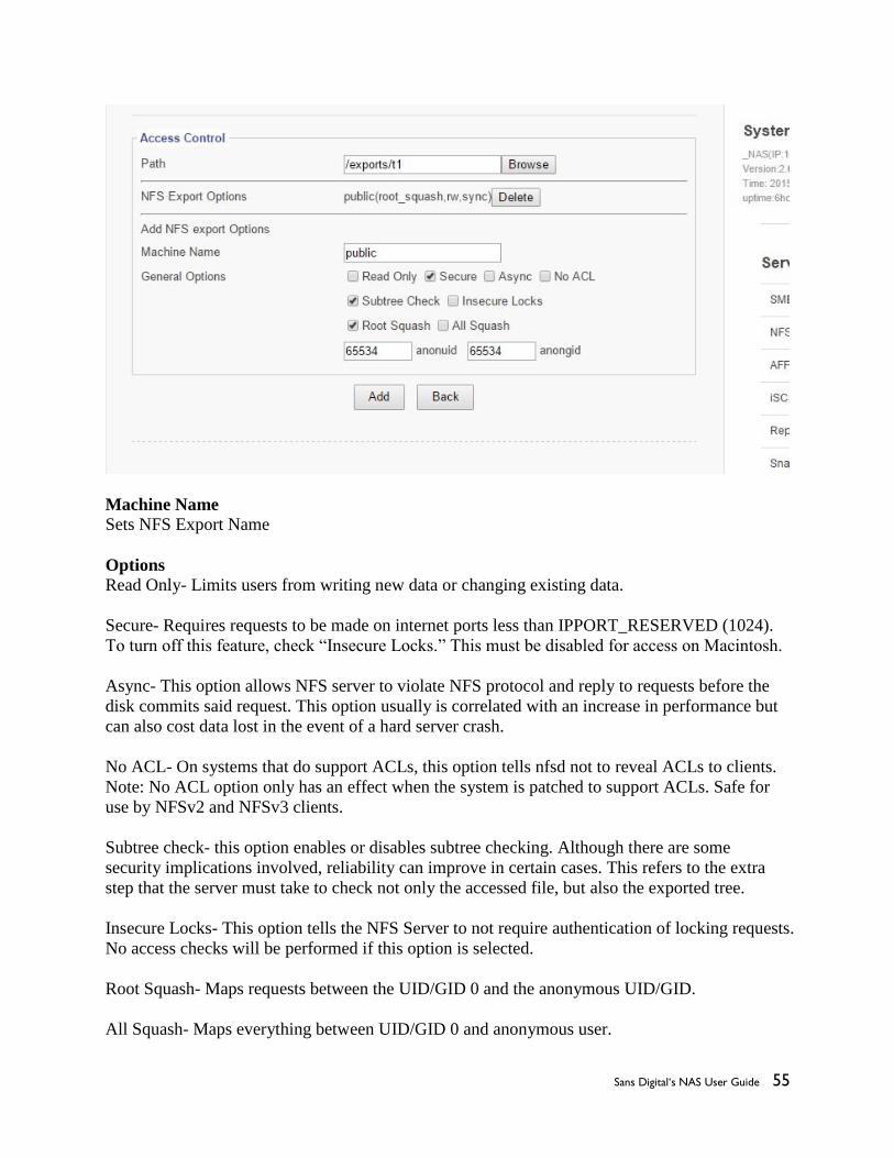
5.2a Edit NFS Access Controls
Sans Digital‘s NAS User Guide 55
Machine Name
Sets NFS Export Name
Options
Read Only- Limits users from writing new data or changing existing data.
Secure- Requires requests to be made on internet ports less than IPPORT_RESERVED (1024).
To turn off this feature, check “Insecure Locks.” This must be disabled for access on Macintosh.
Async- This option allows NFS server to violate NFS protocol and reply to requests before the
disk commits said request. This option usually is correlated with an increase in performance but
can also cost data lost in the event of a hard server crash.
No ACL- On systems that do support ACLs, this option tells nfsd not to reveal ACLs to clients.
Note: No ACL option only has an effect when the system is patched to support ACLs. Safe for
use by NFSv2 and NFSv3 clients.
Subtree check- this option enables or disables subtree checking. Although there are some
security implications involved, reliability can improve in certain cases. This refers to the extra
step that the server must take to check not only the accessed file, but also the exported tree.
Insecure Locks- This option tells the NFS Server to not require authentication of locking requests.
No access checks will be performed if this option is selected.
Root Squash- Maps requests between the UID/GID 0 and the anonymous UID/GID.
All Squash- Maps everything between UID/GID 0 and anonymous user.

Sans Digital‘s NAS User Guide 56
Anonuid and Anongid- Explicitly set the uid and gid of anonymous user. Usually this feature is
used if one wants all users accessing to seem like 1 user.
5.3 Service AFP/Atalk
The Apple Filing Protocol (AFP)
Use this sub-menu to access the control panel to manage client access to the Apple Talk Service.
Path
Use this function to set the location of the share.

Sans Digital‘s NAS User Guide 57
Name
Use this function to name the share. The adjacent option box enables or disables the share.
Assigned Users This window displays users who have been granted access to the share.
User/Group List & Permissions
This window displays all available users who can be granted access to the share. To grant a user
access, click on their name and chose an option of: “Read/Write, Read Only, or Deny.” To save
change, click “add.”
Options
Drop down bar
None-No changes will be made
Tolower- forces all names to be lower case for both directions of the share.
Toupper- forces all names to be upper case for both directions of the share.
Xlatelower- AFP client sees lower case and client sees upper case
Xlateupper- AFP client sees upper case and client sees lower case
Mswindows- checking this option box improves performance for Windows NT, 2000 and 2003
systems.
Prodos- This function improves communication with Legacy Apple II OS.
CRLF Conversion- This feature converts line feeds and carriage returns from UNIX to
Windows and AFP compatible formats.
Read Only- This option forces read only communication
Nohex- This option disables hex translations for all files but DOT files
Usedots- This option shows file names with configurations that begin with “.”
Limitsize- This option limits each file to a 2GB maximum.
File/Directory Permissions Set- Sets default permissions for users accessing files via: AFP.
Follow this format:
A code is used with this format “0” followed by 3 numbers. (0XXX).
The first X refers to the owner of the file/directory.
The Second X refers to the group assigned to the file/directory
The third X refers to other users assigned to the file/directory
These numbers “X” Can take a total of 6 values.
4- Read Only

Sans Digital‘s NAS User Guide 58
2- Write Only
1—Execute Only
5 (4+1) Read and Execute Only
6 (4+2) Read and Write Only
7 (4+2+1) Read, Execute, and Write
Example
0742
Owner has all rights
Group assigned can read only
Other groups can write only
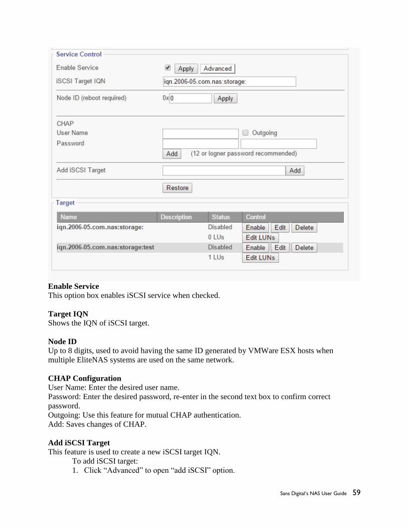
5.4 Service iSCSI Target page: iSCSI Target Service Management
This sub menu displays the settings to enable/disable access via iSCSI.
Sans Digital‘s NAS User Guide 59
Enable Service
This option box enables iSCSI service when checked.
Target IQN
Shows the IQN of iSCSI target.
Node ID Up to 8 digits, used to avoid having the same ID generated by VMWare ESX hosts when
multiple EliteNAS systems are used on the same network.
CHAP Configuration
User Name: Enter the desired user name.
Password: Enter the desired password, re-enter in the second text box to confirm correct
password.
Outgoing: Use this feature for mutual CHAP authentication.
Add: Saves changes of CHAP.
Add iSCSI Target
This feature is used to create a new iSCSI target IQN.
To add iSCSI target:
1. Click “Advanced” to open “add iSCSI” option.

Sans Digital‘s NAS User Guide 60
2. Copy “iSCSI Target IQN.”
3. Paste “iSCSI Target IQN” into “Add iSCSI Target” Text box
4. Enter a name after the IQN Target (ie. iqn.2006-05.com.nas:storage:backup)
5. Click “Add” to save changes.
Restore Use this function to restart SCST services. This helps restore connection with existing iSCSI
targets.
Target Enable/Disable- used to grant/prevent access to iSCSI Target
Edit- Use this function to edit iSCSI target functions:. IQN Name, IQN Description, CHAP
controls, Host IP Block, and Logical Volumes Assignments.
Edit LUNS- Used to manage block-type logical volume access via iSCSI Target
Edit LUNS
1. Target- shows iSCSI Target selected for editing.
2. Options- Grants permission to write or read only.
3. Access Control- Used to add/delete initiators from EliteNAS.
4. Volumes- displays current Logical Volumes assigned to this target.
5. Logical Volumes- To add LUN, enter a LUN number and click “add.” Entry will now be
visible on the “Volumes” box.
5.5 Service Replication page:

Sans Digital‘s NAS User Guide 61
This sub-menu displays the settings to configure EliteNAS to replicate to another remote
EliteNAS system.
5.5a Adding a new Replication Schedule
1. Click “add” button to access the Replication Schedule editor screen.
2. Name- Set name for replication job.
3. Source- click “browse” to find source volume.
4. Target- click “browse” to find target volume.

Sans Digital‘s NAS User Guide 62
5. Enable the “Enable Replication Scheduling” option.
6. Enable the “Delete files on Target that no longer exist in Source” option
7. Enable the “File Compression” option if so desired.
8. Enable the “Full File Copy, No Incremental Checks” option if desired.
9. Enter a value for bandwidth limitation if so desired.
10. Enter the number of revisions desired.
11. Set desired Replication Schedule
12. Click “save” to apply changes.
5.6 Service Snapshot page
This sub menu allows for managing of scheduled snapshot services.
5.6a Adding new Snapshot Schedule
1. Snapshot Name- Enter desired name of snapshot schedule.
2. Volume List- Select the desired volume from the drop down menu.
3. Description- Enter a description for the snapshot schedule to aid in identification.
4. Size- Enter the desired snapshot size.
5. Frequency- Set the desired frequency of snapshots.
6. Click “Create” to save changes and add the new Snapshot schedule.

Sans Digital‘s NAS User Guide 63
5.7 Service Access Control page:
This sub menu houses the settings to control user access to shared file directories/ group
permissions.
5.7a Edit
Use this button to open menu to configure user access controls.

Sans Digital‘s NAS User Guide 64
Name
Displays the user that is being edited.
Owner
Drop down menu that sets the owner of the share.
Group
Drop down menu that sets a group to assign user to.
Search User/Group
Feature used to search for a specific user or group.
Permissions Used to set certain permissions granted to owner, group, others, or sticky.
Apply to all sub directories and files
Used to chose whom is affected by changes in settings.
Assigned users
This window displays all users assigned.
Group/User List This window displays each user and group.
Permissions
Used to set permissions for slected users or groups.
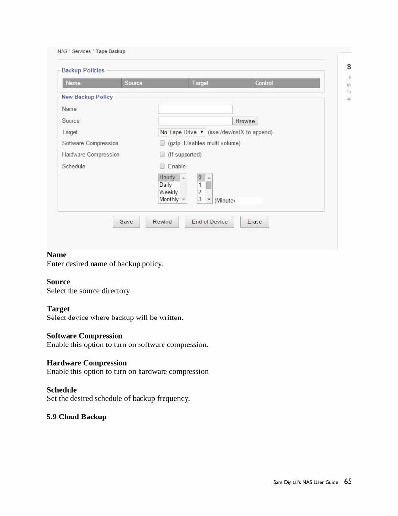
5.8Tape Backup
This page displays the settings to manage tape backups.
Sans Digital‘s NAS User Guide 65
Name
Enter desired name of backup policy.
Source Select the source directory
Target
Select device where backup will be written.
Software Compression
Enable this option to turn on software compression.
Hardware Compression
Enable this option to turn on hardware compression
Schedule
Set the desired schedule of backup frequency.
5.9 Cloud Backup

Sans Digital‘s NAS User Guide 66
Services
Select service provider for Cloud Backup service
Name
Enter the desired name of the backup.
Source Directory
Choose a source directory from the browse list.
Target Directory Choose a target directory from the browse list.
Delete deleted files
Checking this option box deletes files that have been deleted.
Checkers Enter number of checkers to run in parallel.
Transfers Enter number of file transfers to run in parallel.

Sans Digital‘s NAS User Guide 67
Schedule
Check this option box to enable cloud backup scheduling.
Enter schedule desired for cloud backup.
Chapter 6: Top-Menu-Entry: “Features”
“Features” entry consists of the following sub-menu entries/pages:

Sans Digital‘s NAS User Guide 68
6.1 Features FTP Service Management
Enable Service
This check option box enables FTP Service.
Create Home on User Login Enabling this feature automatically creates a “home” folder for the user.
Allow Anonymous Access
Enabling this feature grants anonymous users access to the FTP folder.
Allow Upload Enabling this feature allows users to upload files to the FTP folder.
Anonymous Root
Use the browse button to select a location for the Anonymous Root folder.
Enable SSL

Sans Digital‘s NAS User Guide 69
Enables SSL encrypted communication between User and FTP Service
Generate PEM-Generates certificate for SSL service.
Force Anonymous Logins to use SSL- Forces Anonymous Users to only access via SSL.
Force Anonymous Data to use SSL- Forces data transmissions to be logged as “Anonymous
User“ on FTP.
Force Logins to use SSL- Forces all logins to use SSL encryption.
Force Data to use SSL- Forces all data to use SSL encryption.
Enable/Disable FTP Shares
Click the button to enable/disable FTP Shares.
6.2 Features DHCP Management
This sub menu contains the options for configuring the DHCP Service
1. Enter IP address range that will be given to clients.
2. Enter a desired subnet mask IP
3. Enter a desired netmask IP
4. Enter a desired Gateway IP
5. Enter the Primary DNS IP
6. Enter the Secondary DNS IP
7. Enter the length of lease term desired.
8. Select Apply to save changes.

Sans Digital‘s NAS User Guide 70
6.3 Features Network Time Service Management
To enable NTP Service:
1. Check the “Enable Service” option box.
2. Select a pre-existing NTP Server or add a new NTP server by entering its IP address and
subnet fields and clicking ‘add.”
3. Click the “Sync Once” button sync NTP Service with the NTP Server.
Add/Remove NTP Clients 1. Enter IP address of client
2. Click “add” to add client, click “delete” to remove client.
3. Click the “Sync Once” button to sync NTP Service with the NTP Server.
4.
6.4 Features UPNP
UPNP stands for Universal Plug and Play, this feature allows users to see each other’s presences
on the network for data sharing.

Sans Digital‘s NAS User Guide 71
To Enable UPNP:
1. Check “Enable Service” option box.
2. Enter a desired “name” of share.
3. Enter desired “path” of the share.
4. Click “Apply” to save changes.
6.5 Features DDNS Management
This page displays the menu for configuring the DDNS Service
To enable DDNS Service:
1. Check the “Enable Service” option box.
2. Select a service via the drop down menu.
3. Enter a desired username for the DDNS Service Account
4. Enter a desired password for the DDNS Service Account.
5. Enter a DDNS Alias
6. Enter a DDNS Update frequency (seconds)
6.6 Features Remote Access Management
This page displays the settings for configuring Remote Access.

Sans Digital‘s NAS User Guide 72
Enable Web GUI Access
Select this option box to enable web browser access to the Graphical User Interface.
Enable Web GUI HTTPS Access Select this option box to enable secure browser access to the Graphical User Interface.
Enable Telnet Access Select this option box to enable access via Telnet connections.
Enable Web HDD Access
Allows users to access their own folder via Web GUI instead of FTP or SMB.
SCP Access
Selecting this option box directs the use of a Secure Copy access
SFTP Access
Enable this option for Secure File Transfer Protocol access.
Chapter 7: Top-Menu-Entry: “Status”
“Status” entry consists of the following sub-menu entries/pages:

Sans Digital‘s NAS User Guide 73
The Status menu shows an array of information to help ensure that your EliteNAS system is
running at an optimal level.
7.1 Status Statistics

Sans Digital‘s NAS User Guide 74
This page provides real time data of CPU, System Memory, Volumes, and Network Usage.
7.2 Status Log
The log page displays a list of events: shutdowns, reboots, critical software erros, ect.
Refresh
Updates log to show most recent activity.
Download
Saves the entire log as a .txt file. (Useful if contacting technical support)
Clear Warning
Removes all outstanding warnings.
Remove
Clears entire EliteNAS log.

Sans Digital‘s NAS User Guide 75
7.3 Status User Access
This page displays all users currently connected to the EliteNAS system. The page also displays
open shared files and folders.
Hitting Refresh makes the page show the most current data.
7.4 Status Notification page:
This menu displays the settings for configuring communication with internal and external SMTP
servers to provide information to IT staff.

Sans Digital‘s NAS User Guide 76
SMTP Server
Simple Mail Transport Protocol used to send email notifications.
User Name Usually is the email address of the person receiving notifications
Password Password of User’s Mail Account
From
Used to identify device generating notifications. (optional)
Email Addresses
Enter email addresses of all persons monitoring and maintaining EliteNAS.
TLS/SSL
Usually required if communicating with SMTP servers, ie smtp.google.com or
[email protected]. Note: SMTP communications may not function without this setting.
Starttls
Enabling this feature tells the SMTP application to use TLS. Note: SMTP Server communication
may not function without this setting.
SSMTP
Enabling this feature sets up the SSMTP program to deliver an email from a local computer to a
mailhub. Mainly used for forwarding automated emails to an external email.
SMTP Debug
Enabling this feature keeps a log of SMTP communications.
Send Test Email
Sends a test email to ensure email system is functioning correctly.
7.5 Status SNMP
This page displays the setting to enable SNMP Service on EliteNAS.
SNMP, short for Simple Network Management Protocol is used to manage networks. SNMP can
be used to configure network devices such as printers, hubs, switches, and servers.
Enable SNMP
1. Check “Enable Service” option box.
2. Click “Apply” to save changes.

Sans Digital‘s NAS User Guide 77
7.6 SMART (Disk & RAID)
This page monitors each iSCSI connection. The system will also occasionally check the SMART
status of each iSCSI connection. A properly functioning system will display “Passed.” If an error
is present a warning will be shown in its place. Clicking “Refresh” prompts the system to reveal
real-time data. Warnings can also be cleared by clicking “Clear Warning”