Sandstone landforms shaped by negative feedback between stress and erosion
5
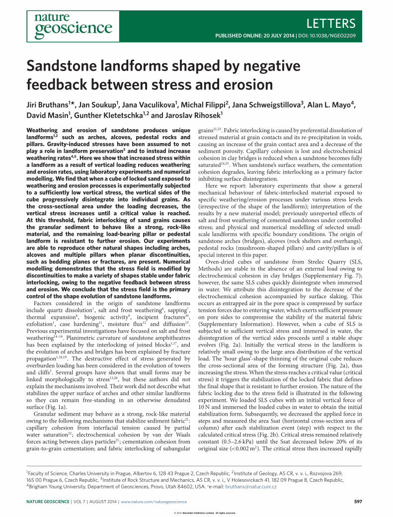
LETTERS PUBLISHED ONLINE: 20 JULY 2014 | DOI: 10.1038/NGEO2209 Sandstone landforms shaped by negative feedback between stress and erosion Jiri Bruthans 1 * , Jan Soukup 1 , Jana Vaculikova 1 , Michal Filippi 2 , Jana Schweigstillova 3 , Alan L. Mayo 4 , David Masin 1 , Gunther Kletetschka 1,2 and Jaroslav Rihosek 1 Weathering and erosion of sandstone produces unique landforms 1,2 such as arches, alcoves, pedestal rocks and pillars. Gravity-induced stresses have been assumed to not play a role in landform preservation 3 and to instead increase weathering rates 4,5 . Here we show that increased stress within a landform as a result of vertical loading reduces weathering and erosion rates, using laboratory experiments and numerical modelling. We find that when a cube of locked sand exposed to weathering and erosion processes is experimentally subjected to a suciently low vertical stress, the vertical sides of the cube progressively disintegrate into individual grains. As the cross-sectional area under the loading decreases, the vertical stress increases until a critical value is reached. At this threshold, fabric interlocking of sand grains causes the granular sediment to behave like a strong, rock-like material, and the remaining load-bearing pillar or pedestal landform is resistant to further erosion. Our experiments are able to reproduce other natural shapes including arches, alcoves and multiple pillars when planar discontinuities, such as bedding planes or fractures, are present. Numerical modelling demonstrates that the stress field is modified by discontinuities to make a variety of shapes stable under fabric interlocking, owing to the negative feedback between stress and erosion. We conclude that the stress field is the primary control of the shape evolution of sandstone landforms. Factors considered in the origin of sandstone landforms include quartz dissolution 1 , salt and frost weathering 6 , sapping 7 , thermal expansion 8 , biogenic activity 9 , incipient fractures 10 , exfoliation 1 , case hardening 11 , moisture flux 12 and diffusion 13 . Previous experimental investigations have focused on salt and frost weathering 14–16 . Planimetric curvature of sandstone amphitheatres has been explained by the interlocking of joined blocks 1,17 , and the evolution of arches and bridges has been explained by fracture propagation 1,18,19 . The destructive effect of stress generated by overburden loading has been considered in the evolution of towers and cliffs 5 . Several groups have shown that small forms may be linked morphologically to stress 13,20 , but these authors did not explain the mechanisms involved. Their work did not describe what stabilizes the upper surface of arches and other similar landforms so they can remain free-standing in an otherwise denudated surface (Fig. 1a). Granular sediment may behave as a strong, rock-like material owing to the following mechanisms that stabilize sediment fabric 21 : capillary cohesion from interfacial tension caused by partial water saturation 22 ; electrochemical cohesion by van der Waals forces acting between clays particles 21 ; cementation cohesion from grain-to-grain cementation; and fabric interlocking of subangular grains 21,23 . Fabric interlocking is caused by preferential dissolution of stressed material at grain contacts and its re-precipitation in voids, causing an increase of the grain contact area and a decrease of the sediment porosity. Capillary cohesion is lost and electrochemical cohesion in clay bridges is reduced when a sandstone becomes fully saturated 24,25 . When sandstone’s surface weathers, the cementation cohesion degrades, leaving fabric interlocking as a primary factor inhibiting surface disintegration. Here we report: laboratory experiments that show a general mechanical behaviour of fabric-interlocked material exposed to specific weathering/erosion processes under various stress levels (irrespective of the shape of the landform); interpretation of the results by a new material model; previously unreported effects of salt and frost weathering of cemented sandstones under controlled stress; and physical and numerical modelling of selected small- scale landforms with specific boundary conditions. The origin of sandstone arches (bridges), alcoves (rock shelters and overhangs), pedestal rocks (mushroom-shaped pillars) and cavity/pillars is of special interest in this paper. Oven-dried cubes of sandstone from Strelec Quarry (SLS, Methods) are stable in the absence of an external load owing to electrochemical cohesion in clay bridges (Supplementary Fig. 7); however, the same SLS cubes quickly disintegrate when immersed in water. We attribute this disintegration to the decrease of the electrochemical cohesion accompanied by surface slaking. This occurs as entrapped air in the pore space is compressed by surface tension forces due to entering water, which exerts sufficient pressure on pore sides to compromise the stability of the material fabric (Supplementary Information). However, when a cube of SLS is subjected to sufficient vertical stress and immersed in water, the disintegration of the vertical sides proceeds until a stable shape evolves (Fig. 2a). Initially the vertical stress in the landform is relatively small owing to the large area distribution of the vertical load. The ‘hour glass’-shape thinning of the original cube reduces the cross-sectional area of the forming structure (Fig. 2a), thus increasing the stress. When the stress reaches a critical value (critical stress) it triggers the stabilization of the locked fabric that defines the final shape that is resistant to further erosion. The nature of the fabric locking due to the stress field is illustrated in the following experiment. We loaded SLS cubes with an initial vertical force of 10 N and immersed the loaded cubes in water to obtain the initial stabilization form. Subsequently, we decreased the applied force in steps and measured the area Ssat (horizontal cross-section area of column) after each stabilization event (step) with respect to the calculated critical stress (Fig. 2b). Critical stress remained relatively constant (0.5–2.6 kPa) until the Ssat decreased below 20% of its original size ( <0.002 m 2 ). The critical stress then increased rapidly 1 Faculty of Science, Charles University in Prague, Albertov 6, 128 43 Prague 2, Czech Republic, 2 Institute of Geology, AS CR, v. v. i., Rozvojova 269, 165 00 Prague 6, Czech Republic, 3 Institute of Rock Structure and Mechanics, AS CR, v. v. i., V Holesovickach 41, 182 09 Prague 8, Czech Republic, 4 Brigham Young University, Department of Geosciences, Provo, Utah 84602, USA. *e-mail: [email protected] NATURE GEOSCIENCE | VOL 7 | AUGUST 2014 | www.nature.com/naturegeoscience 597 © 2014 Macmillan Publishers Limited. All rights reserved.
Transcript of Sandstone landforms shaped by negative feedback between stress and erosion
LETTERSPUBLISHED ONLINE: 20 JULY 2014 | DOI: 10.1038/NGEO2209
Sandstone landforms shaped by negativefeedback between stress and erosionJiri Bruthans1*, Jan Soukup1, Jana Vaculikova1, Michal Filippi2, Jana Schweigstillova3, Alan L. Mayo4,David Masin1, Gunther Kletetschka1,2 and Jaroslav Rihosek1
Weathering and erosion of sandstone produces uniquelandforms1,2 such as arches, alcoves, pedestal rocks andpillars. Gravity-induced stresses have been assumed to notplay a role in landform preservation3 and to instead increaseweathering rates4,5. Here we show that increased stress withina landform as a result of vertical loading reduces weatheringand erosion rates, using laboratory experiments and numericalmodelling.We find that when a cube of locked sand exposed toweathering and erosion processes is experimentally subjectedto a su�ciently low vertical stress, the vertical sides of thecube progressively disintegrate into individual grains. Asthe cross-sectional area under the loading decreases, thevertical stress increases until a critical value is reached.At this threshold, fabric interlocking of sand grains causesthe granular sediment to behave like a strong, rock-likematerial, and the remaining load-bearing pillar or pedestallandform is resistant to further erosion. Our experimentsare able to reproduce other natural shapes including arches,alcoves and multiple pillars when planar discontinuities,such as bedding planes or fractures, are present. Numericalmodelling demonstrates that the stress field is modified bydiscontinuities to make a variety of shapes stable under fabricinterlocking, owing to the negative feedback between stressand erosion. We conclude that the stress field is the primarycontrol of the shape evolution of sandstone landforms.
Factors considered in the origin of sandstone landformsinclude quartz dissolution1, salt and frost weathering6, sapping7,thermal expansion8, biogenic activity9, incipient fractures10,exfoliation1, case hardening11, moisture flux12 and diffusion13.Previous experimental investigations have focused on salt and frostweathering14–16. Planimetric curvature of sandstone amphitheatreshas been explained by the interlocking of joined blocks1,17, andthe evolution of arches and bridges has been explained by fracturepropagation1,18,19. The destructive effect of stress generated byoverburden loading has been considered in the evolution of towersand cliffs5. Several groups have shown that small forms may belinked morphologically to stress13,20, but these authors did notexplain the mechanisms involved. Their work did not describe whatstabilizes the upper surface of arches and other similar landformsso they can remain free-standing in an otherwise denudatedsurface (Fig. 1a).
Granular sediment may behave as a strong, rock-like materialowing to the following mechanisms that stabilize sediment fabric21:capillary cohesion from interfacial tension caused by partialwater saturation22; electrochemical cohesion by van der Waalsforces acting between clays particles21; cementation cohesion fromgrain-to-grain cementation; and fabric interlocking of subangular
grains21,23. Fabric interlocking is caused by preferential dissolution ofstressed material at grain contacts and its re-precipitation in voids,causing an increase of the grain contact area and a decrease of thesediment porosity. Capillary cohesion is lost and electrochemicalcohesion in clay bridges is reduced when a sandstone becomes fullysaturated24,25. When sandstone’s surface weathers, the cementationcohesion degrades, leaving fabric interlocking as a primary factorinhibiting surface disintegration.
Here we report: laboratory experiments that show a generalmechanical behaviour of fabric-interlocked material exposed tospecific weathering/erosion processes under various stress levels(irrespective of the shape of the landform); interpretation of theresults by a new material model; previously unreported effects ofsalt and frost weathering of cemented sandstones under controlledstress; and physical and numerical modelling of selected small-scale landforms with specific boundary conditions. The origin ofsandstone arches (bridges), alcoves (rock shelters and overhangs),pedestal rocks (mushroom-shaped pillars) and cavity/pillars is ofspecial interest in this paper.
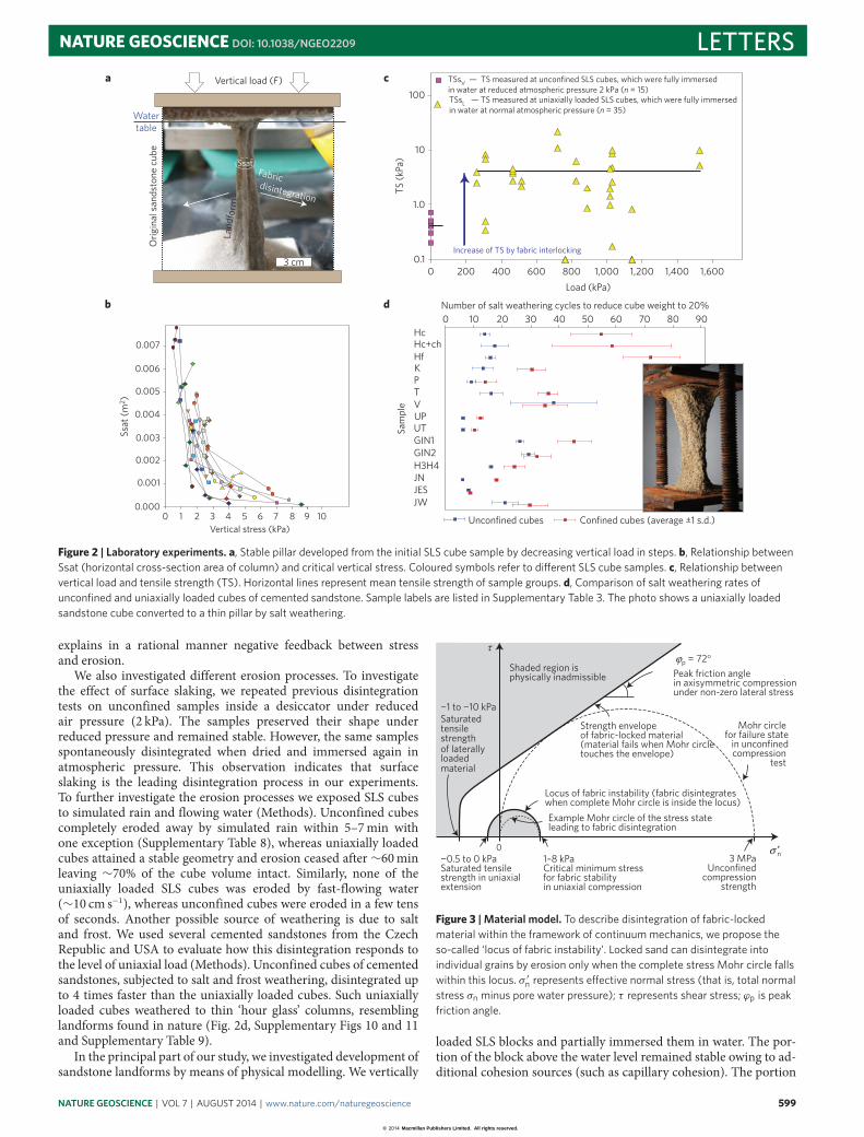
Oven-dried cubes of sandstone from Strelec Quarry (SLS,Methods) are stable in the absence of an external load owing toelectrochemical cohesion in clay bridges (Supplementary Fig. 7);however, the same SLS cubes quickly disintegrate when immersedin water. We attribute this disintegration to the decrease of theelectrochemical cohesion accompanied by surface slaking. Thisoccurs as entrapped air in the pore space is compressed by surfacetension forces due to entering water, which exerts sufficient pressureon pore sides to compromise the stability of the material fabric(Supplementary Information). However, when a cube of SLS issubjected to sufficient vertical stress and immersed in water, thedisintegration of the vertical sides proceeds until a stable shapeevolves (Fig. 2a). Initially the vertical stress in the landform isrelatively small owing to the large area distribution of the verticalload. The ‘hour glass’-shape thinning of the original cube reducesthe cross-sectional area of the forming structure (Fig. 2a), thusincreasing the stress.When the stress reaches a critical value (criticalstress) it triggers the stabilization of the locked fabric that definesthe final shape that is resistant to further erosion. The nature of thefabric locking due to the stress field is illustrated in the followingexperiment. We loaded SLS cubes with an initial vertical force of10N and immersed the loaded cubes in water to obtain the initialstabilization form. Subsequently, we decreased the applied force insteps and measured the area Ssat (horizontal cross-section area ofcolumn) after each stabilization event (step) with respect to thecalculated critical stress (Fig. 2b). Critical stress remained relativelyconstant (0.5–2.6 kPa) until the Ssat decreased below 20% of itsoriginal size (<0.002m2). The critical stress then increased rapidly
1Faculty of Science, Charles University in Prague, Albertov 6, 128 43 Prague 2, Czech Republic, 2Institute of Geology, AS CR, v. v. i., Rozvojova 269,165 00 Prague 6, Czech Republic, 3Institute of Rock Structure and Mechanics, AS CR, v. v. i., V Holesovickach 41, 182 09 Prague 8, Czech Republic,4Brigham Young University, Department of Geosciences, Provo, Utah 84602, USA. *e-mail: [email protected]
NATURE GEOSCIENCE | VOL 7 | AUGUST 2014 | www.nature.com/naturegeoscience 597
© 2014 Macmillan Publishers Limited. All rights reserved.
LETTERS NATURE GEOSCIENCE DOI: 10.1038/NGEO2209
Example from naturea
b
c
d
Physical modelling Stressnumerical modelling
Free
-sta
ndin
g ar
chA
lcov
e P
edes
tal r
ock
Cav
e pi
llars
Explanation for numerical modelling: Principal stress direction and magnitudeFabric-interlocked material The maximum level of immersion
5 cm
5 cm
5 cm
5 cm
5 m
Figure 1 | Sandstone landforms and modelling. a–d, Examples of the selected common sandstone landforms (first column) and their artificial equivalentsresulting from partial immersion of SLS rectangular blocks (second column). The third column presents numerical models showing principal stressdirections and magnitudes indicating the stability of these landforms. Location of the natural landforms is as follows: a, Delicate Arch, Arches NationalPark, USA. b, Alcove, Navajo Blu� area, USA. c, Pedestal rock, Angel Arch area, Canyonlands National Park, Utah, USA. d, Cave pillars, Eladio Cave, ChuriTepui, Venezuela. Photos courtesy of V. Cilek (b,c) and M. Audy (d).
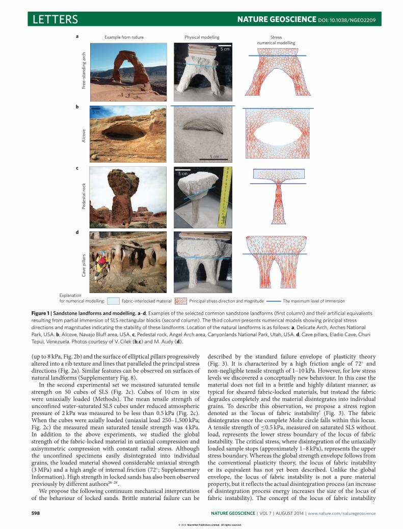
(up to 8 kPa, Fig. 2b) and the surface of elliptical pillars progressivelyaltered into a rib texture and lines that paralleled the principal stressdirections (Fig. 2a). Similar features can be observed on surfaces ofnatural landforms (Supplementary Fig. 8).
In the second experimental set we measured saturated tensilestrength on 50 cubes of SLS (Fig. 2c). Cubes of 10 cm in sizewere uniaxially loaded (Methods). The mean tensile strength ofunconfined water-saturated SLS cubes under reduced atmosphericpressure of 2 kPa was measured to be less than 0.5 kPa (Fig. 2c).When the cubes were axially loaded (uniaxial load 250–1,500 kPa;Fig. 2c) the measured mean saturated tensile strength was 4 kPa.In addition to the above experiments, we studied the globalstrength of the fabric-locked material in uniaxial compression andaxisymmetric compression with constant radial stress. Althoughthe unconfined specimens easily disintegrated into individualgrains, the loaded material showed considerable uniaxial strength(3MPa) and a high angle of internal friction (72◦; SupplementaryInformation). High strength in locked sands has also been observedpreviously by different authors26–28.
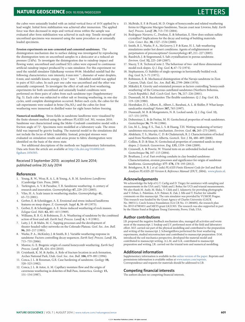
We propose the following continuum mechanical interpretationof the behaviour of locked sands. Brittle material failure can be
described by the standard failure envelope of plasticity theory(Fig. 3). It is characterized by a high friction angle of 72◦ andnon-negligible tensile strength of 1–10 kPa. However, for low stresslevels we discovered a conceptually new behaviour. In this case thematerial does not fail in a brittle and highly dilatant manner, astypical for sheared fabric-locked materials, but instead the fabricdegrades completely and the material disintegrates into individualgrains. To describe this observation, we propose a stress regiondenoted as the ‘locus of fabric instability’ (Fig. 3). The fabricdisintegrates once the complete Mohr circle falls within this locus.A tensile strength of ≤0.5 kPa, measured on saturated SLS withoutload, represents the lower stress boundary of the locus of fabricinstability. The critical stress, where disintegration of the uniaxiallyloaded sample stops (approximately 1–8 kPa), represents the upperstress boundary. Whereas the global strength envelope follows fromthe conventional plasticity theory, the locus of fabric instabilityor its equivalent has not yet been described. Unlike the globalenvelope, the locus of fabric instability is not a pure materialproperty, but it reflects the actual disintegration process (an increaseof disintegration process energy increases the size of the locus offabric instability). The concept of the locus of fabric instability
598 NATURE GEOSCIENCE | VOL 7 | AUGUST 2014 | www.nature.com/naturegeoscience
© 2014 Macmillan Publishers Limited. All rights reserved.
NATURE GEOSCIENCE DOI: 10.1038/NGEO2209 LETTERS
0.1
1.0
10
Load (kPa)
TS (k
Pa)
TSsV — TS measured at unconfined SLS cubes, which were fully immersed in water at reduced atmospheric pressure 2 kPa (n = 15) TSsL — TS measured at uniaxially loaded SLS cubes, which were fully immersed in water at normal atmospheric pressure (n = 35)
Increase of TS by fabric interlocking
Confined cubes (average ±1 s.d.)Unconfined cubes
Number of salt weathering cycles to reduce cube weight to 20%
Hc+chHfKPT
UTUPV
H3H4GIN2GIN1
Hc
JWJESJN
Vertical stress (kPa)
Ssat
(m2 )
Sam
ple
100
3 cm
Watertable
Orig
inal
san
dsto
ne c
ube
Ssat
Land
form
Vertical load (F)
Fabric disintegration
0 200 400 600 800 1,000 1,200 1,400 1,600
0.000
0.001
0.002
0.003
0.004
0.005
0.006
0.007
a c
db
0 1 2 3 4 5 6 7 8 9 10
0 10 20 30 40 50 60 70 80 90
Figure 2 | Laboratory experiments. a, Stable pillar developed from the initial SLS cube sample by decreasing vertical load in steps. b, Relationship betweenSsat (horizontal cross-section area of column) and critical vertical stress. Coloured symbols refer to di�erent SLS cube samples. c, Relationship betweenvertical load and tensile strength (TS). Horizontal lines represent mean tensile strength of sample groups. d, Comparison of salt weathering rates ofunconfined and uniaxially loaded cubes of cemented sandstone. Sample labels are listed in Supplementary Table 3. The photo shows a uniaxially loadedsandstone cube converted to a thin pillar by salt weathering.
explains in a rational manner negative feedback between stressand erosion.
We also investigated different erosion processes. To investigatethe effect of surface slaking, we repeated previous disintegrationtests on unconfined samples inside a desiccator under reducedair pressure (2 kPa). The samples preserved their shape underreduced pressure and remained stable. However, the same samplesspontaneously disintegrated when dried and immersed again inatmospheric pressure. This observation indicates that surfaceslaking is the leading disintegration process in our experiments.To further investigate the erosion processes we exposed SLS cubesto simulated rain and flowing water (Methods). Unconfined cubescompletely eroded away by simulated rain within 5–7min withone exception (Supplementary Table 8), whereas uniaxially loadedcubes attained a stable geometry and erosion ceased after ∼60minleaving ∼70% of the cube volume intact. Similarly, none of theuniaxially loaded SLS cubes was eroded by fast-flowing water(∼10 cm s−1), whereas unconfined cubes were eroded in a few tensof seconds. Another possible source of weathering is due to saltand frost. We used several cemented sandstones from the CzechRepublic and USA to evaluate how this disintegration responds tothe level of uniaxial load (Methods). Unconfined cubes of cementedsandstones, subjected to salt and frost weathering, disintegrated upto 4 times faster than the uniaxially loaded cubes. Such uniaxiallyloaded cubes weathered to thin ‘hour glass’ columns, resemblinglandforms found in nature (Fig. 2d, Supplementary Figs 10 and 11and Supplementary Table 9).
In the principal part of our study, we investigated development ofsandstone landforms by means of physical modelling. We vertically
0
−1 to −10 kPaSaturated tensile strengthof laterallyloadedmaterial
Locus of fabric instability (fabric disintegrateswhen complete Mohr circle is inside the locus)
−0.5 to 0 kPaSaturated tensile strength in uniaxial extension
1–8 kPaCritical minimum stress for fabric stability in uniaxial compression
3 MPaUnconfined
compression strength
Peak friction anglein axisymmetric compressionunder non-zero lateral stress
p = 72°Shaded region isphysically inadmissible
τ
Strength envelopeof fabric-locked material(material fails when Mohr circletouches the envelope)
′n
Example Mohr circle of the stress stateleading to fabric disintegration
Mohr circle for failure state
in unconfinedcompression
test
σ
ϕ
Figure 3 | Material model. To describe disintegration of fabric-lockedmaterial within the framework of continuum mechanics, we propose theso-called ‘locus of fabric instability’. Locked sand can disintegrate intoindividual grains by erosion only when the complete stress Mohr circle fallswithin this locus. σ ′n represents e�ective normal stress (that is, total normalstress σn minus pore water pressure); τ represents shear stress; ϕp is peakfriction angle.
loaded SLS blocks and partially immersed them in water. The por-tion of the block above the water level remained stable owing to ad-ditional cohesion sources (such as capillary cohesion). The portion
NATURE GEOSCIENCE | VOL 7 | AUGUST 2014 | www.nature.com/naturegeoscience 599
© 2014 Macmillan Publishers Limited. All rights reserved.
LETTERS NATURE GEOSCIENCE DOI: 10.1038/NGEO2209
Resistant material
Fabric-interlocked material
Discontinuity:bedding plane, fracture, clay horizon (schematically)
Area of low stress (schematically)
Area of high/very high stress (schematically) Original surface
Accumulated retreat over whole lifetime of landform
Direction and magnitude of instant retreat rate
Seeping groundwater erodingthin layer of material
Fixed erosion base
Present surface
OverburdenOverburdena b c d
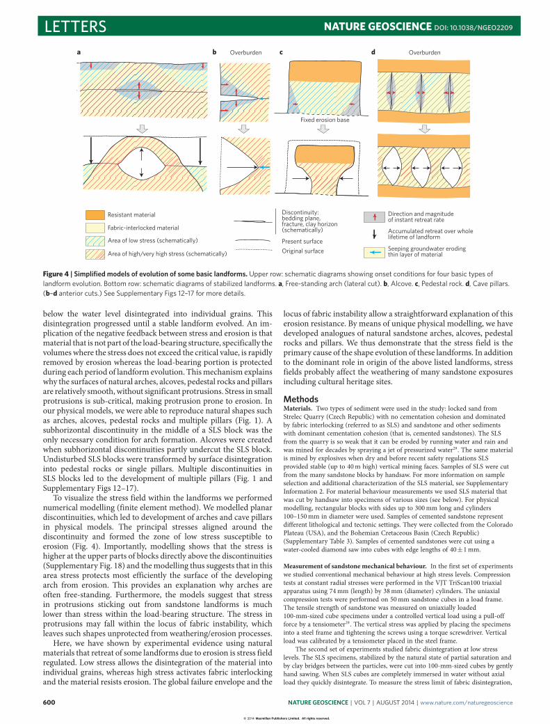
Figure 4 | Simplified models of evolution of some basic landforms. Upper row: schematic diagrams showing onset conditions for four basic types oflandform evolution. Bottom row: schematic diagrams of stabilized landforms. a, Free-standing arch (lateral cut). b, Alcove. c, Pedestal rock. d, Cave pillars.(b–d anterior cuts.) See Supplementary Figs 12–17 for more details.
below the water level disintegrated into individual grains. Thisdisintegration progressed until a stable landform evolved. An im-plication of the negative feedback between stress and erosion is thatmaterial that is not part of the load-bearing structure, specifically thevolumes where the stress does not exceed the critical value, is rapidlyremoved by erosion whereas the load-bearing portion is protectedduring each period of landform evolution. Thismechanism explainswhy the surfaces of natural arches, alcoves, pedestal rocks and pillarsare relatively smooth, without significant protrusions. Stress in smallprotrusions is sub-critical, making protrusion prone to erosion. Inour physical models, we were able to reproduce natural shapes suchas arches, alcoves, pedestal rocks and multiple pillars (Fig. 1). Asubhorizontal discontinuity in the middle of a SLS block was theonly necessary condition for arch formation. Alcoves were createdwhen subhorizontal discontinuities partly undercut the SLS block.Undisturbed SLS blocks were transformed by surface disintegrationinto pedestal rocks or single pillars. Multiple discontinuities inSLS blocks led to the development of multiple pillars (Fig. 1 andSupplementary Figs 12–17).
To visualize the stress field within the landforms we performednumerical modelling (finite element method). We modelled planardiscontinuities, which led to development of arches and cave pillarsin physical models. The principal stresses aligned around thediscontinuity and formed the zone of low stress susceptible toerosion (Fig. 4). Importantly, modelling shows that the stress ishigher at the upper parts of blocks directly above the discontinuities(Supplementary Fig. 18) and themodelling thus suggests that in thisarea stress protects most efficiently the surface of the developingarch from erosion. This provides an explanation why arches areoften free-standing. Furthermore, the models suggest that stressin protrusions sticking out from sandstone landforms is muchlower than stress within the load-bearing structure. The stress inprotrusions may fall within the locus of fabric instability, whichleaves such shapes unprotected from weathering/erosion processes.
Here, we have shown by experimental evidence using naturalmaterials that retreat of some landforms due to erosion is stress fieldregulated. Low stress allows the disintegration of the material intoindividual grains, whereas high stress activates fabric interlockingand the material resists erosion. The global failure envelope and the
locus of fabric instability allow a straightforward explanation of thiserosion resistance. By means of unique physical modelling, we havedeveloped analogues of natural sandstone arches, alcoves, pedestalrocks and pillars. We thus demonstrate that the stress field is theprimary cause of the shape evolution of these landforms. In additionto the dominant role in origin of the above listed landforms, stressfields probably affect the weathering of many sandstone exposuresincluding cultural heritage sites.
MethodsMaterials. Two types of sediment were used in the study: locked sand fromStrelec Quarry (Czech Republic) with no cementation cohesion and dominatedby fabric interlocking (referred to as SLS) and sandstone and other sedimentswith dominant cementation cohesion (that is, cemented sandstones). The SLSfrom the quarry is so weak that it can be eroded by running water and rain andwas mined for decades by spraying a jet of pressurized water29. The same materialis mined by explosives when dry and before recent safety regulations SLSprovided stable (up to 40m high) vertical mining faces. Samples of SLS were cutfrom the many sandstone blocks by handsaw. For more information on sampleselection and additional characterization of the SLS material, see SupplementaryInformation 2. For material behaviour measurements we used SLS material thatwas cut by handsaw into specimens of various sizes (see below). For physicalmodelling, rectangular blocks with sides up to 300mm long and cylinders100–150mm in diameter were used. Samples of cemented sandstone representdifferent lithological and tectonic settings. They were collected from the ColoradoPlateau (USA), and the Bohemian Cretaceous Basin (Czech Republic)(Supplementary Table 3). Samples of cemented sandstones were cut using awater-cooled diamond saw into cubes with edge lengths of 40±1mm.
Measurement of sandstonemechanical behaviour. In the first set of experimentswe studied conventional mechanical behaviour at high stress levels. Compressiontests at constant radial stresses were performed in the VJT TriScan100 triaxialapparatus using 74mm (length) by 38mm (diameter) cylinders. The uniaxialcompression tests were performed on 50mm sandstone cubes in a load frame.The tensile strength of sandstone was measured on uniaxially loaded100-mm-sized cube specimens under a controlled vertical load using a pull-offforce by a tensiometer29. The vertical stress was applied by placing the specimensinto a steel frame and tightening the screws using a torque screwdriver. Verticalload was calibrated by a tensiometer placed in the steel frame.
The second set of experiments studied fabric disintegration at low stresslevels. The SLS specimens, stabilized by the natural state of partial saturation andby clay bridges between the particles, were cut into 100-mm-sized cubes by gentlyhand sawing. When SLS cubes are completely immersed in water without axialload they quickly disintegrate. To measure the stress limit of fabric disintegration,
600 NATURE GEOSCIENCE | VOL 7 | AUGUST 2014 | www.nature.com/naturegeoscience
© 2014 Macmillan Publishers Limited. All rights reserved.
NATURE GEOSCIENCE DOI: 10.1038/NGEO2209 LETTERSthe cubes were uniaxially loaded with an initial vertical force of 10N applied by alead weight. Initial form stabilization was achieved after immersion. The appliedforce was then decreased in steps and vertical stress within the sample wasevaluated after form stabilization was achieved in each step. Tensile strength ofunconfined specimens was measured using the same procedure as at uniaxiallyloaded specimens.
Erosion experiments on non-cemented and cemented sandstones. Thedisintegration mechanism due to surface slaking was investigated by reproducingthe disintegration tests on unconfined samples in a desiccator at a reduced airpressure (2 kPa). To investigate the disintegration due to raindrop impact andflowing water, unconfined and confined SLS cubes were exposed to continuousartificial raindrop impact produced by a rain simulator. For this experiment weused the rainfall simulator Eijkelkamp version 09.06. Modelled rainfall had thefollowing characteristics: rain intensity, 6mmmin−1; diameter of water droplets,6mm; and rainfall’s kinetic energy, 4 Jm−2 mm−1. Modelled rainfall was appliedto pairs of SLS cubes. In each pair one cube was unconfined and the other wasuniaxially compressed. To investigate the effect of salt and frost weathering,experiments for both unconfined and uniaxially loaded conditions wereperformed on three pairs of cubes from each sandstone type (SupplementaryFig. 5). Each cube was subjected to either salt or freezing weathering, in one-daycycles, until complete disintegration occurred. Before each cycle, the cubes for thesalt experiments were soaked in brine (Na2SO4) and the cubes for frostweathering were immersed in distilled water for eight hours before freezing.
Numerical modelling. Stress fields in sandstone landforms were visualized bythe finite-element method using the software PLAXIS (ref. 30), version 2010.Sandstone was characterized using the Mohr–Coulomb constitutive model with afriction angle of 72◦. Specimens were modelled at a laboratory scale. The stressfield was imposed by gravity loading. The material model in the simulations didnot include the locus of fabric instability. Instead, principal stresses wereevaluated on simulation results and areas prone to fabric disintegration wereidentified on the basis of the stress state.
For additional descriptions of the methods see Supplementary Information.Data sets from the article are available at http://dx.doi.org/10.6084/m9.figshare.1056303.
Received 3 September 2013; accepted 20 June 2014;published online 20 July 2014
References1. Young, R. W., Wray, R. A. L. & Young, A. R. M. Sandstone Landforms
(Cambridge Univ. Press, 2009).2. Turkington, A. V. & Paradise, T. R. Sandstone weathering: A century of
research and innovation. Geomorphology 67, 229–253 (2005).3. Viles, H. A. Scale issues in weathering studies. Geomorphology 41,
63–72 (2001).4. Gerber, E. & Scheidegger, A. E. Erosional and stress-induced landforms
features on steep slopes. Z. Geomorph. Suppl. 8, 38–49 (1973).5. Gerber, E. & Scheidegger, A. E. Stress-induced weathering of rock masses.
Eclogae Geol. Helv. 62, 401–415 (1969).6. Williams, R. B. G. & Robinson, D. A. Weathering of sandstone by the combined
action of frost and salt. Earth Surf. Process. Landf. 6, 1–9 (1981).7. Laity, J. E. & Malin, M. C. Sapping processes and the development of
theater-headed valley networks on the Colorado Plateau. Geol. Soc. Am. Bull.96, 203–217 (1985).
8. Warke, P. A., McKinley, J. & Smith, B. J. Variable weathering response insandstone: Factors controlling decay sequences. Earth Surf. Process. Landf. 31,715–735 (2006).
9. Mustoe, G. E. Biogenic origin of coastal honeycomb weathering. Earth Surf.Process. Landf. 35, 424–434 (2010).
10. Cruishank, K. M. & Aydin, A. Role of fracture location in arch formation,Arches National Park, Utah. Geol. Soc. Am. Bull. 106, 879–891 (1994).
11. Conca, J. L. & Rossman, G.R. Case hardening of sandstone. Geology 10,520–523 (1982).
12. Conca, J. L. & Astor, A. M. Capillary moisture flow and the origin ofcavernous weathering in dolerites of Bull Pass, Antarctica. Geology 15,151–154 (1987).
13. McBride, E. F. & Picard, M. D. Origin of honeycombs and related weatheringforms in Oligocene Macigno Sandstone, Tuscan coast near Livorno, Italy. EarthSurf. Process. Landf. 29, 713–735 (2004).
14. Rodriguez-Navarro, C., Doehne, E. & Sebastian, E. How does sodium sulfatecrystallize? Implications for the decay and testing of building materials.Cem. Concr. Res. 30, 1527–1534 (2000).
15. Smith, B. J., Warke, P. A., McGreevy, J. P. & Kane, H. L. Salt-weatheringsimulations under hot desert conditions: Agents of enlightenment orperpetuators of preconceptions? Geomorphology 67, 211–227 (2005).
16. Ruedrich, J. & Siegesmund, S. Salt crystallisation in porous sandstone.Environ. Geol. 52, 225–249 (2007).
17. Stacey, T. R. Technical note 2. The behaviour of two- and three-dimensionalmodel rock slopes. Q. J. Eng. Geol. 8, 67–72 (1974).
18. Stephansson, O. Stability of single openings in horizontally bedded rock.Eng. Geol. 5, 5–71 (1971).
19. Robinson, E. R. Mechanical disintegration of the Navajo sandstone in ZionCanyon, Utah. Geol. Soc. Am. Bull. 81, 2799–2806 (1970).
20. Mikuláš, R. Gravity and orientated pressure as factors controlling ‘honeycombweathering’ of the Cretaceous castellated sandstones (Northern Bohemia,Czech Republic). Bull. Czech Geol. Surv. 76, 217–226 (2001).
21. Dusseault, M. B. Itacolumites: The flexible sandstones. Q. J. Eng. Geol. 13,119–128 (1980).
22. Hornbaker, D. J., Albert, R., Albert, I., Barabasi, A. L. & Shiffer, P. What keepssandcastles standing? Nature 387, 765 (1997).
23. Dusseault, M. B. & Morgenstern, N. R. Locked sands. Q. J. Eng. Geol. 12,117–131 (1979).
24. Dobereiner, L. & de Freitas, M. H. Geotechnical properties of weak sandstones.Geotechnique 36, 79–94 (1986).
25. Lin, M. L., Jeng, F. S., Tsai, L. S. & Huang, T.H. Wetting weakening of tertiarysandstones-microscopic mechanism. Environ. Geol. 48, 265–275 (2005).
26. Abdelaziz, T. S., Martin, C. D. & Chalaturnyk, R. J. Characterization of lockedsand from Northeastern Alberta. Geotech. Test. J. 31, 480–489 (2008).
27. Collins, B. D. & Sitar, N. Geotechnical properties of cemented sands in steepslopes. J. Geotech. Geoenviron. Eng. 135, 1359–1366 (2009).
28. Cresswell, A. & Powrie, W. Triaxial tests on an unbonded locked sand.Geotechnique 54, 107–115 (2004).
29. Bruthans, J. et al. Fast evolving conduits in clay-bonded sandstone:Characterization, erosion processes and significance for origin of sandstonelandforms. Geomorphology 177–178, 178–193 (2012).
30. Brinkgreve, R. B. J. et al. (eds) PLAXIS Finite Element Code for Soil and RockAnalyses PLAXIS-2D Version 8, Reference Manual (DUT, 2004); www.plaxis.nl.
AcknowledgementsWe acknowledge the help of G.T. Carlig and D. Tingey for assistance with sampling andmeasurements in the USA and J. Valek and J. Bohac for UCS and triaxial measurements.We also thank M. Audy, M. Sluka, V. Cilek and J. Adamovic for providing photographsand V. Erban, L. Palatinus, A.N. Palmer, K. Zak, J. Mls and T. Fischer for valuablecomments on this manuscript. The rain simulator was provided by VUMOP, Prague.This research was funded by the Grant Agency of Charles University (GAUKNo. 380511), Czech Science Foundation (GA CR No. 13-28040S), the research planNo. RVO 67985831 and MEYS grant LK21303. The research was also supported in partby the Hintze Fund at Brigham Young University, Provo, Utah, USA.
Author contributionsJ.B. proposed the negative feedback mechanism idea, managed all activities and wrotemost of the manuscript. J. Soukup and J.V. performed most of the field and laboratoryeffort. M.F. carried out part of the physical modelling and contributed to the preparationand writing of the manuscript. J. Schweigstillova performed the frost weatheringexperiments, studied microstructure and contributed to manuscript preparation. D.M.introduced the soil mechanics perspective, developed the material model andcontributed to manuscript writing. A.L.M. and G.K. contributed to manuscriptpreparation and writing. J.R. carried out the triaxial tests and numerical modelling.
Additional informationSupplementary information is available in the online version of the paper. Reprints andpermissions information is available online at www.nature.com/reprints.Correspondence and requests for materials should be addressed to J.B.
Competing financial interestsThe authors declare no competing financial interests.
NATURE GEOSCIENCE | VOL 7 | AUGUST 2014 | www.nature.com/naturegeoscience 601
© 2014 Macmillan Publishers Limited. All rights reserved.