Sandra C. Saldaña - IRIS · PDF fileSandra C. Saldaña. 2 Outline ... Seismic...
52
Fundamentals of Seismic Acquisition & Processing IRIS Intern Orientation 2011 Sandra C. Saldaña
-
Upload
truongnhan -
Category
Documents
-
view
215 -
download
1
Transcript of Sandra C. Saldaña - IRIS · PDF fileSandra C. Saldaña. 2 Outline ... Seismic...

Fundamentals ofSeismic Acquisition &Processing
IRIS Intern Orientation2011
Sandra C. Saldaña

2
Outline
Concepts
Seismic Reflection Acquisition
Seismic Reflection Processing
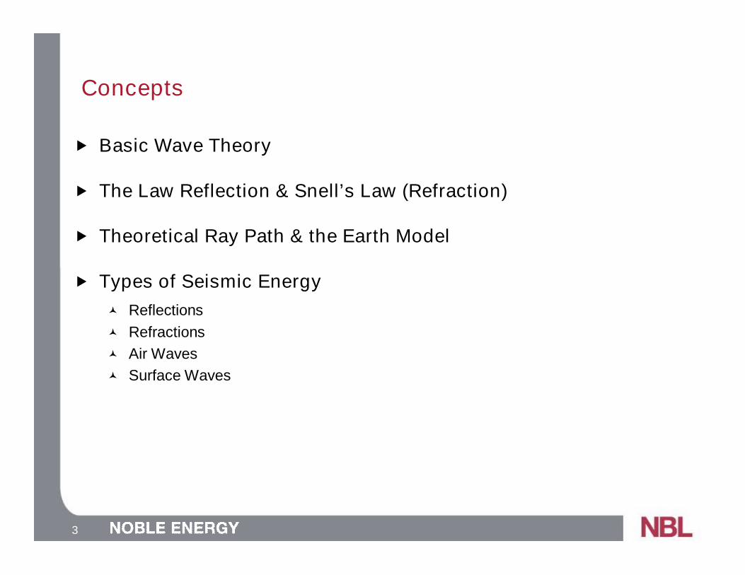
3
Concepts
Basic Wave Theory
The Law Reflection & Snell’s Law (Refraction)
Theoretical Ray Path & the Earth Model
Types of Seismic Energy
Reflections
Refractions
Air Waves
Surface Waves

4
Concepts: Basic Wave Theory
Halliday et al., 2002

5
Concepts: Basic Wave Theory
Halliday et al., 2002

6
Concepts: Basic Wave Theory
Halliday et al., 2002
RayWave Front

7
Concepts: Basic Wave Theory
Halliday et al., 2002

8
Slow Fast Fast Slow
Concepts: Law of Reflection & Snell’s Law
Keary et al., 2002
q1
q1
q2
V1<V2
V1
V2
q1
q1
q2
V1>V2
V1
V2

9
Concepts: Theoretical Ray Path & Earth Model
Keary et al., 2002
Vsand=1800 m/s
Vshale=2500 m/s
Vsand=3000 m/s
Vcarbonate=4100 m/s
Vwater=1520 m/s20º

10
Concepts: Types of Seismic Energy
Reflections
Air Wave
Surface Wave
Refractions
20º

11
Seismic Reflection Acquisition
Definitions
Geophone
Common Midpoint (CMP)
Resolution
Fresnel Zone
Tuning Thickness

12
Definitions: Geophone
http://www.iongeo.com/Land_Imaging/Geophones/http://www.google.com/imgres?imgurl=http://micromachine.stanford.edu/smssl/projects/Geophones/GeophoneColorSketch.jpeg&imgrefurl=http://micromachine.stanford.edu/smssl/projects/Geophones/&h=288&w=396&sz=40&tbnid=A3tBS206DhsgEM:&tbnh=90&tbnw=124&prev=/search%3Fq%3Dgeophone%26tbm%3Disch%26tbo%3Du&zoom=1&q=geophone&hl=en&usg=__w-mO0DRWgF5RtleHveY9SSHeoFY=&sa=X&ei=cnnWTcqfBsq2tge-2NSsBw&ved=0CCAQ9QEwBQ
13
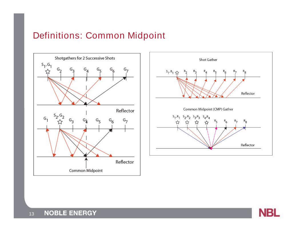
Definitions: Common Midpoint
14
Definitions: Common Midpoint
Movie

15
Definitions: Common Midpoint
CMP Location 100

16
Resolution: Fresnel Zone
Determines Lateral Resolution
Keary et al., 2002
Source
Wave Fronts
Ray
Target
l
l/4

17
Resolution: Tuning Thickness
Determines Vertical Resolution
Keary et al., 2002
Source
Wave Fronts
Ray
Target
l
l/4
18
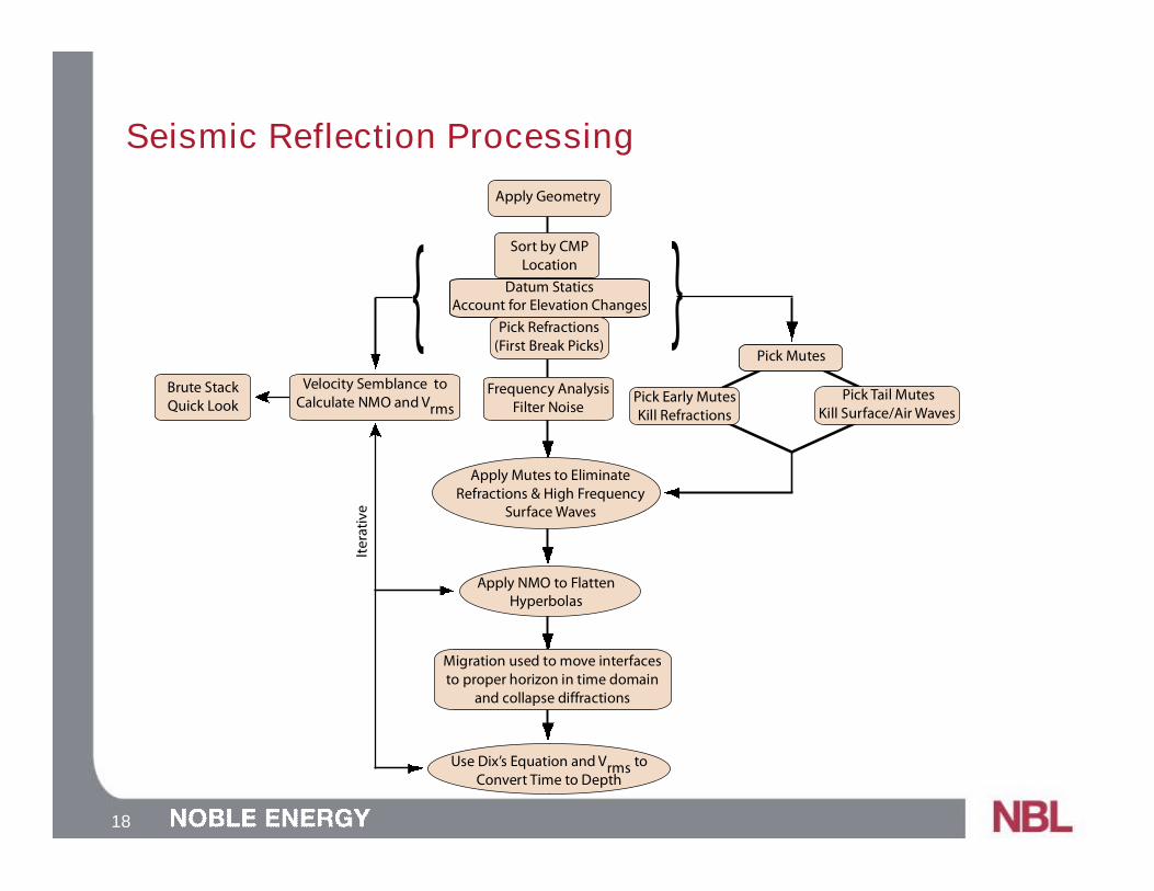
Seismic Reflection Processing
Frequency AnalysisFilter Noise
Apply Geometry
Sort by CMPLocation
Apply Mutes to EliminateRefractions & High Frequency
Surface Waves
Use Dix’s Equation and Vrms toConvert Time to Depth
Apply NMO to FlattenHyperbolas
Migration used to move interfacesto proper horizon in time domain
and collapse diffractions
Pick Mutes
Pick Tail MutesKill Surface/Air Waves
Pick Early MutesKill Refractions
Itera
tive
Velocity Semblance toCalculate NMO and Vrms
Brute StackQuick Look
Datum StaticsAccount for Elevation Changes
Pick Refractions(First Break Picks)
{ {

19
Frequency AnalysisFilter Noise
Apply Geometry
Sort by CMPLocation
Apply Mutes to EliminateRefractions & High Frequency
Surface Waves
Use Dix’s Equation and Vrms toConvert Time to Depth
Apply NMO to FlattenHyperbolas
Migration used to move interfacesto proper horizon in time domain
and collapse diffractions
Pick Mutes
Pick Tail MutesKill Surface/Air Waves
Pick Early MutesKill Refractions
Itera
tive
Velocity Semblance toCalculate NMO and Vrms
Brute StackQuick Look
Datum StaticsAccount for Elevation Changes
Pick Refractions(First Break Picks)
{ {
Seismic Reflection Processing: Geometry

20
Seismic Reflection Processing: Geometry
Raw Shot Gathers – What You’ll See in the Field
We have to tell the computer where each trace is located on the ground...
TraceField File Number Channel Number

21
Seismic Reflection Processing: Geometry
Raw Data
Operation: ComputerStores a Location on theground for each trace
Where EachHammer Hit is onthe Ground
Where Each Channel(Geophone) is on theGround
Which FFID goes withWhich Source Location
Output File

22
Seismic Reflection Processing: Geometry

23
Seismic Reflection Processing: Geometry

24
Seismic Reflection Processing: Geometry
Shot Gathers Post Geometry Function
Offset Geophone’s Distance From the Hammer

25
Frequency AnalysisFilter Noise
Apply Geometry
Sort by CMPLocation
Apply Mutes to EliminateRefractions & High Frequency
Surface Waves
Use Dix’s Equation and Vrms toConvert Time to Depth
Apply NMO to FlattenHyperbolas
Migration used to move interfacesto proper horizon in time domain
and collapse diffractions
Pick Mutes
Pick Tail MutesKill Surface/Air Waves
Pick Early MutesKill Refractions
Itera
tive
Velocity Semblance toCalculate NMO and Vrms
Brute StackQuick Look
Datum StaticsAccount for Elevation Changes
Pick Refractions(First Break Picks)
{ {
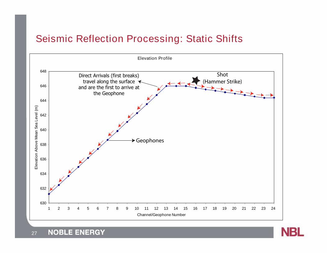
Seismic Reflection Processing: Static Shifts

26
Seismic Reflection Processing: Static Shifts
Elevation Profile
630
632
634
636
638
640
642
644
646
648
1 2 3 4 5 6 7 8 9 10 11 12 13 14 15 16 17 18 19 20 21 22 23 24
Channel/Geophone Number
Ele
vati
on
Ab
ove
Mean
Sea
Level(m
)
Fault Scarp
27
Elevation Profile
630
632
634
636
638
640
642
644
646
648
1 2 3 4 5 6 7 8 9 10 11 12 13 14 15 16 17 18 19 20 21 22 23 24
Channel/Geophone Number
Ele
vati
on
Ab
ove
Mean
Sea
Level(m
)
Shot(Hammer Strike)
Geophones
Seismic Reflection Processing: Static Shifts
Direct Arrivals (first breaks)travel along the surface
and are the first to arrive atthe Geophone
28
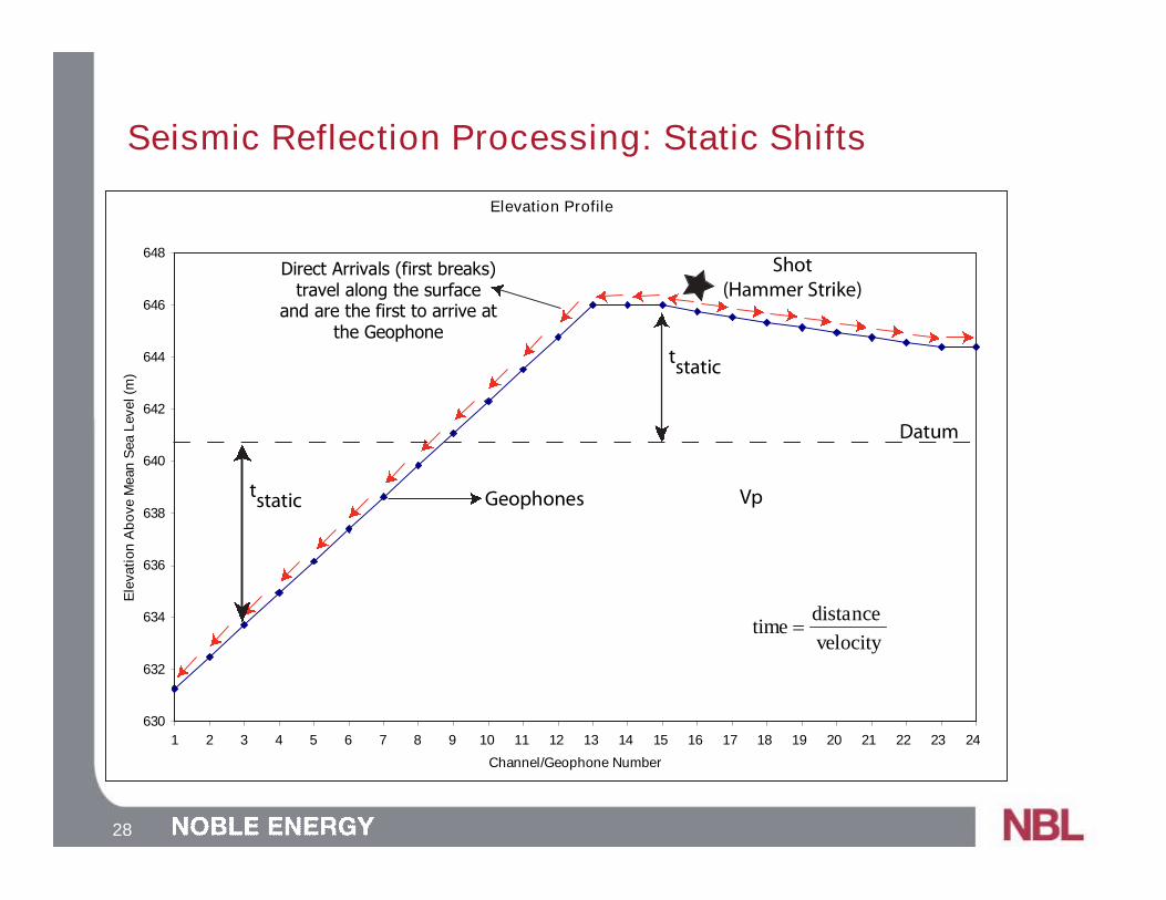
Seismic Reflection Processing: Static Shifts
Elevation Profile
630
632
634
636
638
640
642
644
646
648
1 2 3 4 5 6 7 8 9 10 11 12 13 14 15 16 17 18 19 20 21 22 23 24
Channel/Geophone Number
Ele
vati
on
Ab
ove
Mean
Sea
Level(m
)
Shot(Hammer Strike)
Geophones
Datum
Vp
velocity
distancetime =
tstatic
tstatic
Direct Arrivals (first breaks)travel along the surface
and are the first to arrive atthe Geophone

29
Seismic Reflection Processing: Static Shifts
Shot Gather First Break Picks

30
Seismic Reflection Processing: Static Shifts
Use First Breaks to Calculate tstatic forEach Receiver & Source
Operation: Apply tstatic (shift) to each trace
Operation: Sort Tracesby CMP Location
Create Output File
31
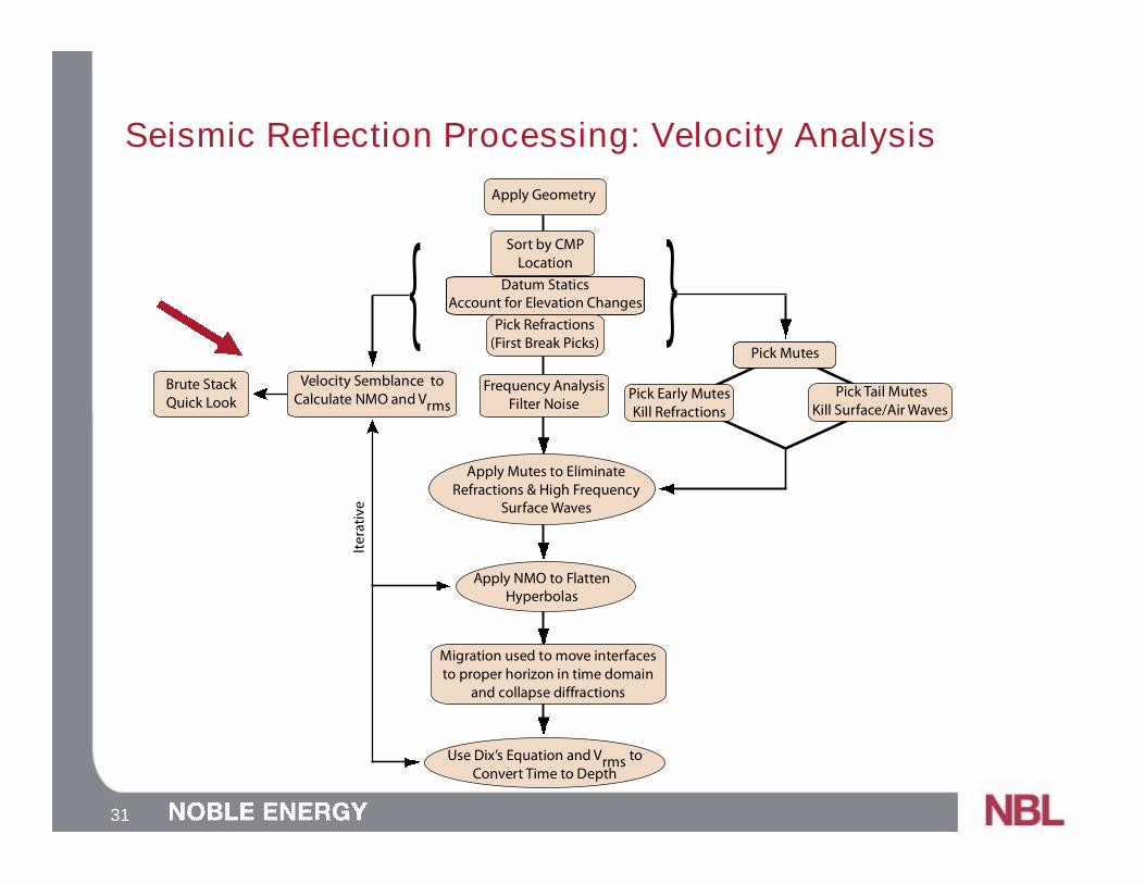
Seismic Reflection Processing: Velocity Analysis
Frequency AnalysisFilter Noise
Apply Geometry
Sort by CMPLocation
Apply Mutes to EliminateRefractions & High Frequency
Surface Waves
Use Dix’s Equation and Vrms toConvert Time to Depth
Apply NMO to FlattenHyperbolas
Migration used to move interfacesto proper horizon in time domain
and collapse diffractions
Pick Mutes
Pick Tail MutesKill Surface/Air Waves
Pick Early MutesKill Refractions
Itera
tive
Velocity Semblance toCalculate NMO and Vrms
Brute StackQuick Look
Datum StaticsAccount for Elevation Changes
Pick Refractions(First Break Picks)
{ {
32
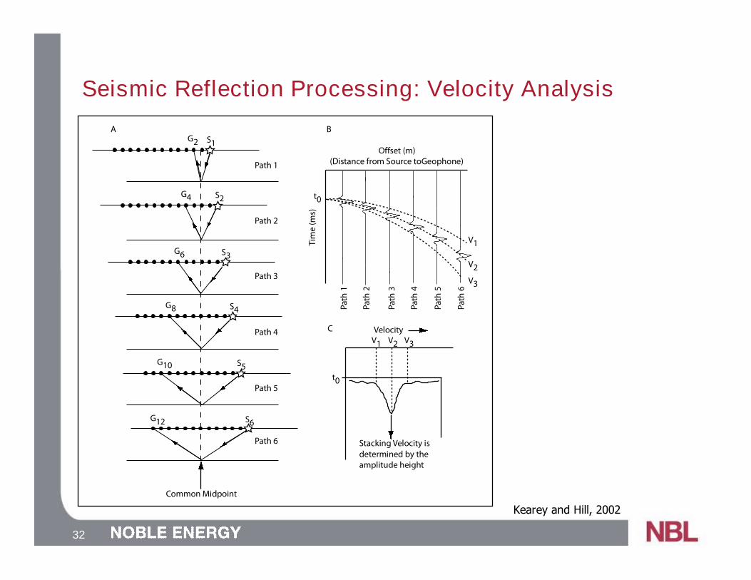
Seismic Reflection Processing: Velocity Analysis
G2 S1
G4 S2
G6 S3
G8 S4
G10 S5
G12 S6
Common Midpoint
Path 1
Path 2
Path 3
Path 4
Path 5
Path 6
t0
Tim
e(m
s)
Offset (m)(Distance from Source toGeophone)
V1
V2V3
Path
1
Path
2
Path
3
Path
4
Path
5
Path
6
Stacking Velocity isdetermined by theamplitude height
VelocityV1 V2 V3
t0
A B
C
Kearey and Hill, 2002

33
Seismic Reflection Processing: Velocity Analysis
G2 S1
G4 S2
G6 S3
G8 S4
G10 S5
G12 S6
Common Midpoint
Path 1
Path 2
Path 3
Path 4
Path 5
Path 6
t0
Tim
e(m
s)
Offset (m)(Distance from Source toGeophone)
V1
V2V3
Path
1
Path
2
Path
3
Path
4
Path
5
Path
6Stacking Velocity isdetermined by theamplitude height
VelocityV1 V2 V3
t0
A B
C
Kearey and Hill, 2002

34
Seismic Reflection Processing: Velocity Analysis
Flattening Hyperbolas movie

35
Seismic Reflection Processing: Velocity Analysis

36
Seismic Reflection Processing: Velocity Analysis
Think About the Geologic Setting:
What do we expect the seismic to look like?
What happens to the rock in the fault zone?
How does this affect the acoustic wave propagation?
How do you expect it to affect the seismic image?

37
Seismic Reflection Processing: Velocity Analysis
Top: Photo mosaic of the natural trench. Bottom: Interpretation of the trench. Notethe location of two strands of the California Wash Fault(provided by Bidgoli et al., 2003).
Fault Locations
Fault LocationsChannel 12
38
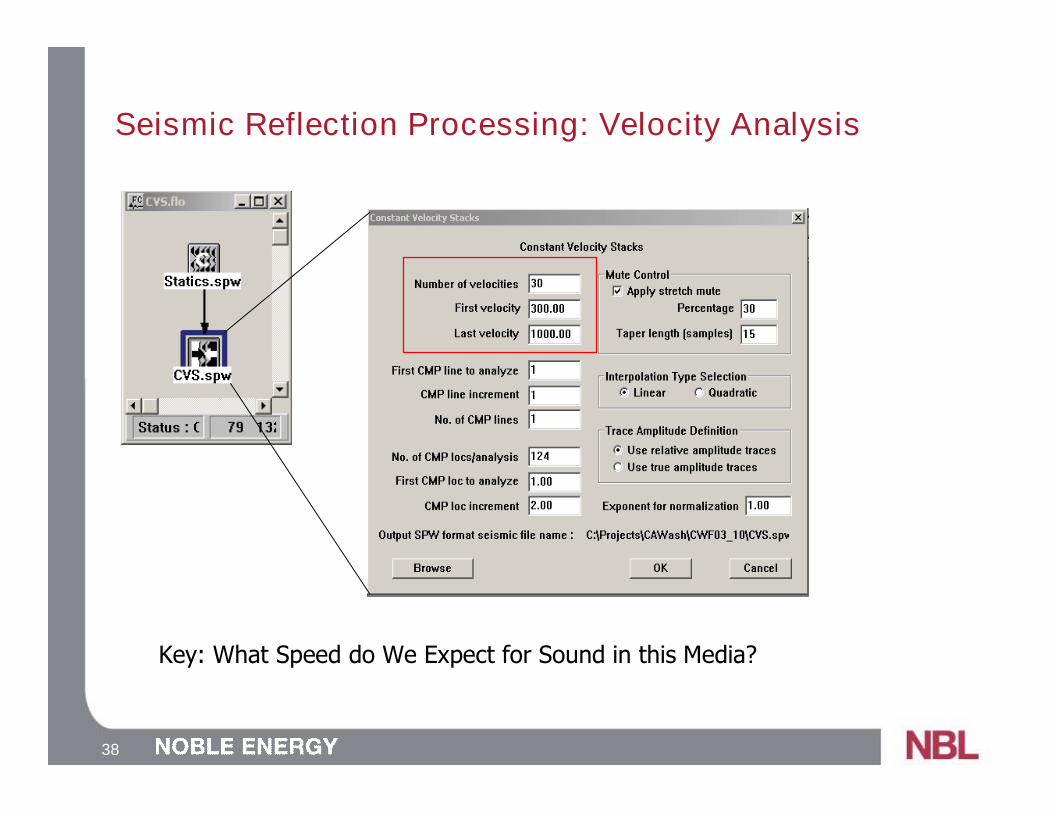
Seismic Reflection Processing: Velocity Analysis
Key: What Speed do We Expect for Sound in this Media?

39
Seismic Reflection Processing: Velocity Analysis
300 361 422 483 544 605 666 727 789 850
Stacking Velocity (m/s)
300 361 422 483 544 605 666 727 789 850
Stacking Velocity (m/s)
Note: Assumes laterally continuous Earth layers!
40
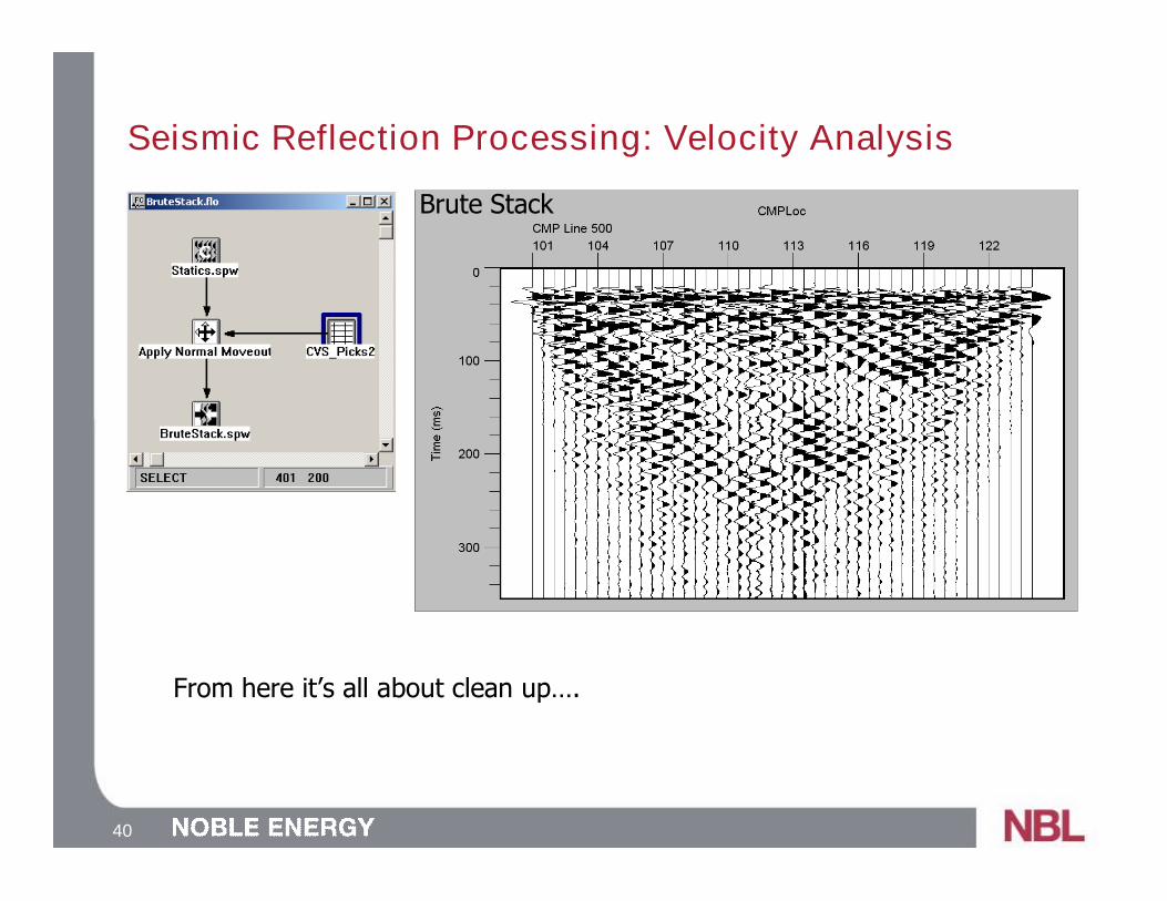
Seismic Reflection Processing: Velocity Analysis
From here it’s all about clean up….
Brute Stack

41
Frequency AnalysisFilter Noise
Apply Geometry
Sort by CMPLocation
Apply Mutes to EliminateRefractions & High Frequency
Surface Waves
Use Dix’s Equation and Vrms toConvert Time to Depth
Apply NMO to FlattenHyperbolas
Migration used to move interfacesto proper horizon in time domain
and collapse diffractions
Pick Mutes
Pick Tail MutesKill Surface/Air Waves
Pick Early MutesKill Refractions
Itera
tive
Velocity Semblance toCalculate NMO and Vrms
Brute StackQuick Look
Datum StaticsAccount for Elevation Changes
Pick Refractions(First Break Picks)
{ {
Seismic Reflection Processing: Frequency Analysis

42
Seismic Reflection Processing: Frequency Analysis
Fourier Transform Amplitude SpectrumThe Earth is a filter,where’s the frequencycontent?

43
Seismic Reflection Processing: Frequency Analysis
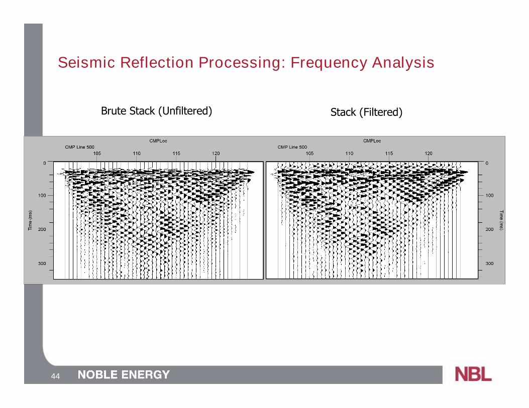
44
Seismic Reflection Processing: Frequency Analysis
Brute Stack (Unfiltered) Stack (Filtered)

45
Frequency AnalysisFilter Noise
Apply Geometry
Sort by CMPLocation
Apply Mutes to EliminateRefractions & High Frequency
Surface Waves
Use Dix’s Equation and Vrms toConvert Time to Depth
Apply NMO to FlattenHyperbolas
Migration used to move interfacesto proper horizon in time domain
and collapse diffractions
Pick Mutes
Pick Tail MutesKill Surface/Air Waves
Pick Early MutesKill Refractions
Itera
tive
Velocity Semblance toCalculate NMO and Vrms
Brute StackQuick Look
Datum StaticsAccount for Elevation Changes
Pick Refractions(First Break Picks)
{ {
Seismic Reflection Processing: Muting

46
Seismic Reflection Processing: Muting
Refractions
Reflections
Surface Waves
Shot Gather Mute Everything but the
reflections
Reflections are only a smallpart of the energy
Better at long offsets
47
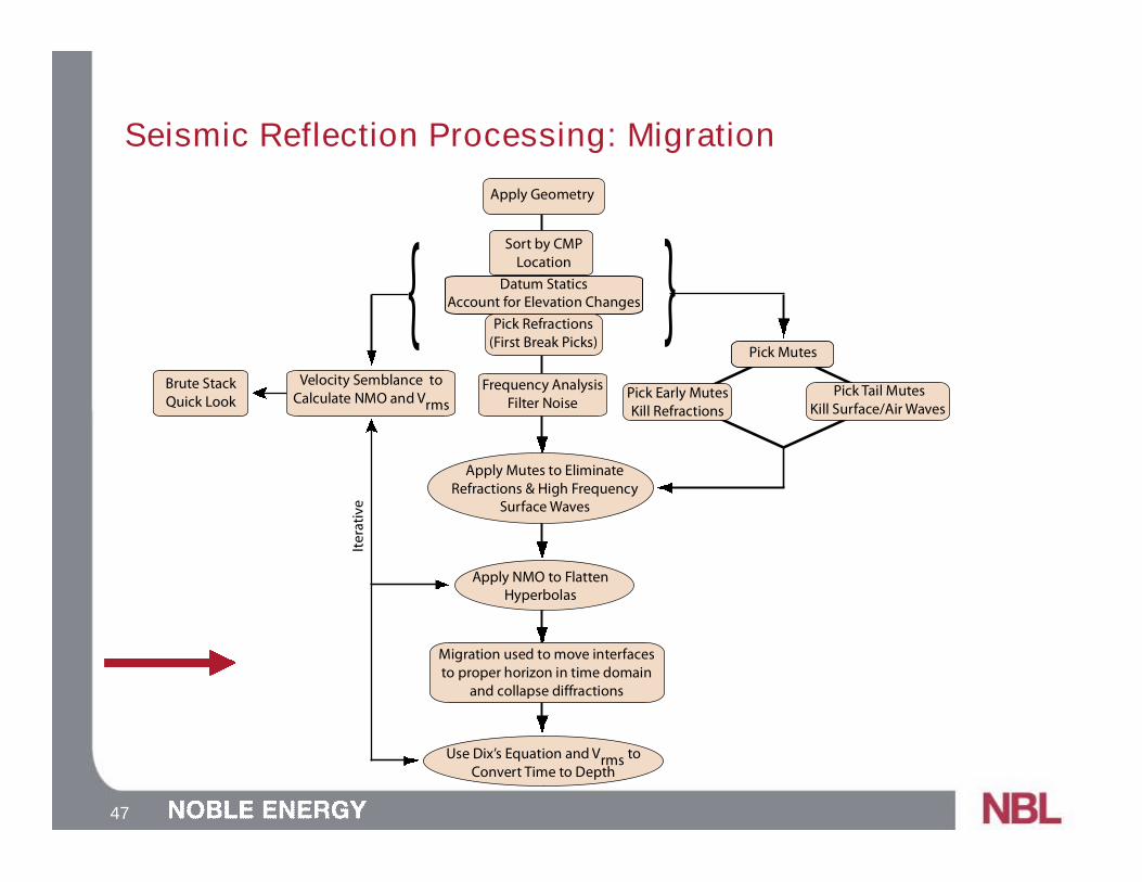
Seismic Reflection Processing: Migration
Frequency AnalysisFilter Noise
Apply Geometry
Sort by CMPLocation
Apply Mutes to EliminateRefractions & High Frequency
Surface Waves
Use Dix’s Equation and Vrms toConvert Time to Depth
Apply NMO to FlattenHyperbolas
Migration used to move interfacesto proper horizon in time domain
and collapse diffractions
Pick Mutes
Pick Tail MutesKill Surface/Air Waves
Pick Early MutesKill Refractions
Itera
tive
Velocity Semblance toCalculate NMO and Vrms
Brute StackQuick Look
Datum StaticsAccount for Elevation Changes
Pick Refractions(First Break Picks)
{ {

48
Seismic Reflection Processing: Migration
Explain Migration

49
Seismic Reflection Processing: Depth Conversion
Frequency AnalysisFilter Noise
Apply Geometry
Sort by CMPLocation
Apply Mutes to EliminateRefractions & High Frequency
Surface Waves
Use Dix’s Equation and Vrms toConvert Time to Depth
Apply NMO to FlattenHyperbolas
Migration used to move interfacesto proper horizon in time domain
and collapse diffractions
Pick Mutes
Pick Tail MutesKill Surface/Air Waves
Pick Early MutesKill Refractions
Itera
tive
Velocity Semblance toCalculate NMO and Vrms
Brute StackQuick Look
Datum StaticsAccount for Elevation Changes
Pick Refractions(First Break Picks)
{ {

50
Seismic Reflection Processing: Depth Conversion

51
Seismic Reflection Processing: Depth Conversion