Sanctuary I Linear Gas Fire Pit Table Manual
18
Sanctuary 1 Outdoor Fire Feature Installation and Operating Instructions IF YOU CANNOT READ OR UNDERSTAND THESE INSTALLATION INSTRUCTIONS DO NOT ATTEMPT TO INSTALL OR OPERATE THIS APPLIANCE Warning: For Outdoor Use Only PLEASE RETAIN THIS MANUAL FOR FUTURE REFERENCE Ventilation is incorporated into all Sanctuary Series Fire Features Natural Gas Description SAN1-30LHTMSI-N 56” x 38” x 16” Rectangular TMSI Model MODEL WARNING: Do not operate this fire feature in high-wind conditions. Operating in high-wind conditions may expose your model to direct flame, which will result in cracking and discoloration to the finish. THE BURNER SYSTEM FOR THE SANCTUARY 1 COMES WITH ITS OWN SEPERATE MANUAL HOWEVER, USE THIS MANUAL FOR ACTUAL INSTALLATION INTO THE SANCTUARY 1
Transcript of Sanctuary I Linear Gas Fire Pit Table Manual

Sanctuary 1 Outdoor Fire FeatureInstallation and Operating Instructions
IF YOU CANNOT READ OR UNDERSTAND THESE INSTALLATION INSTRUCTIONS DO NOT ATTEMPT TO INSTALL OR OPERATE THIS APPLIANCE
Warning: For Outdoor Use Only
PLEASE RETAIN THIS MANUAL FOR FUTURE REFERENCE
Ventilation is incorporated into all Sanctuary Series Fire Features
Natural Gas DescriptionSAN1-30LHTMSI-N 56” x 38” x 16” Rectangular TMSI Model
MODEL
OFF
OFF
ON
OFF
LOW
HI
WARNING: Do not operate this fire feature in high-wind conditions. Operating in high-wind conditions may expose your model to direct flame, which will result in cracking and discoloration to the finish.
THE BURNER SYSTEM FOR THE SANCTUARY 1 COMES WITH ITS OWN SEPERATE MANUAL HOWEVER, USE THIS MANUAL
FOR ACTUAL INSTALLATION INTO THE SANCTUARY 1
REV. 1-23-19 Page 2Sanctuary 1 Fire Feature
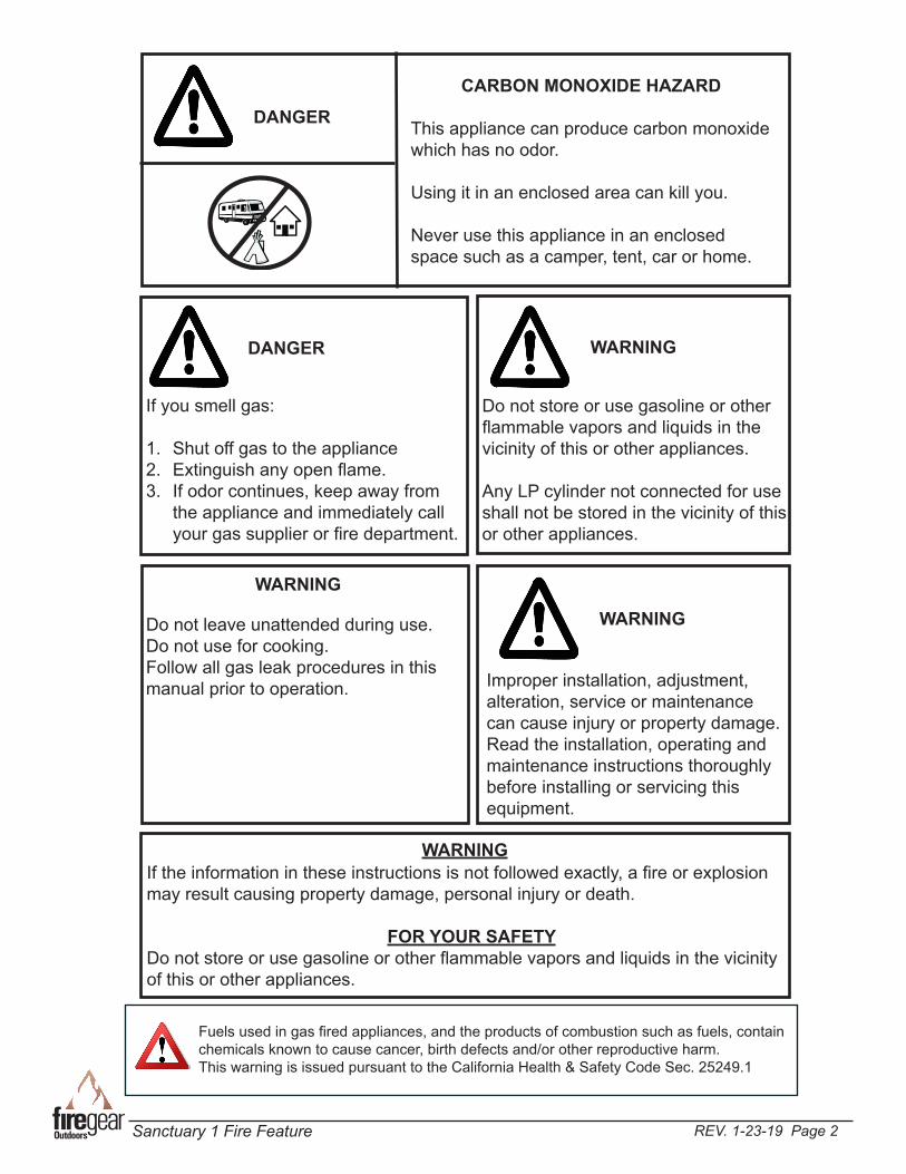
Fuels used in gas fired appliances, and the products of combustion such as fuels, contain chemicals known to cause cancer, birth defects and/or other reproductive harm. This warning is issued pursuant to the California Health & Safety Code Sec. 25249.1
DANGER
CARBON MONOXIDE HAZARD
This appliance can produce carbon monoxide which has no odor.
Using it in an enclosed area can kill you.
Never use this appliance in an enclosed space such as a camper, tent, car or home.
If you smell gas:
1. Shut off gas to the appliance2. Extinguish any open flame.3. If odor continues, keep away from
the appliance and immediately call your gas supplier or fire department.
DANGER WARNING
Do not store or use gasoline or other flammable vapors and liquids in the vicinity of this or other appliances.
Any LP cylinder not connected for use shall not be stored in the vicinity of this or other appliances.
WARNING
Do not leave unattended during use.Do not use for cooking.Follow all gas leak procedures in this manual prior to operation.
WARNING
Improper installation, adjustment, alteration, service or maintenance can cause injury or property damage. Read the installation, operating and maintenance instructions thoroughly before installing or servicing this equipment.
WARNINGIf the information in these instructions is not followed exactly, a fire or explosion may result causing property damage, personal injury or death.
FOR YOUR SAFETYDo not store or use gasoline or other flammable vapors and liquids in the vicinity of this or other appliances.
REV. 1-23-19 Page 3Sanctuary 1 Fire Feature
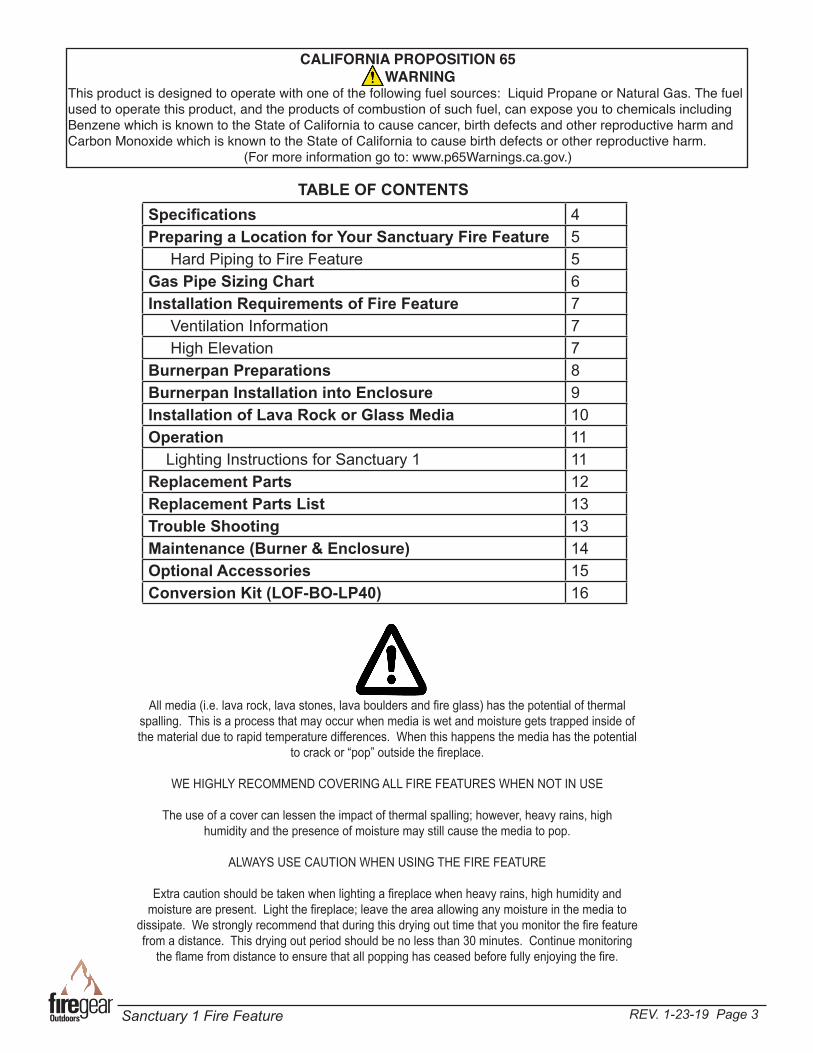
Specifications 4Preparing a Location for Your Sanctuary Fire Feature 5 Hard Piping to Fire Feature 5Gas Pipe Sizing Chart 6Installation Requirements of Fire Feature 7 Ventilation Information 7 High Elevation 7Burnerpan Preparations 8Burnerpan Installation into Enclosure 9Installation of Lava Rock or Glass Media 10Operation 11 Lighting Instructions for Sanctuary 1 11Replacement Parts 12Replacement Parts List 13Trouble Shooting 13Maintenance (Burner & Enclosure) 14Optional Accessories 15Conversion Kit (LOF-BO-LP40) 16
TABLE OF CONTENTS
All media (i.e. lava rock, lava stones, lava boulders and fire glass) has the potential of thermal spalling. This is a process that may occur when media is wet and moisture gets trapped inside of the material due to rapid temperature differences. When this happens the media has the potential
to crack or “pop” outside the fireplace.
WE HIGHLY RECOMMEND COVERING ALL FIRE FEATURES WHEN NOT IN USE
The use of a cover can lessen the impact of thermal spalling; however, heavy rains, high humidity and the presence of moisture may still cause the media to pop.
ALWAYS USE CAUTION WHEN USING THE FIRE FEATURE
Extra caution should be taken when lighting a fireplace when heavy rains, high humidity and moisture are present. Light the fireplace; leave the area allowing any moisture in the media to
dissipate. We strongly recommend that during this drying out time that you monitor the fire feature from a distance. This drying out period should be no less than 30 minutes. Continue monitoring
the flame from distance to ensure that all popping has ceased before fully enjoying the fire.
CALIFORNIA PROPOSITION 65 WARNING
This product is designed to operate with one of the following fuel sources: Liquid Propane or Natural Gas. The fuel used to operate this product, and the products of combustion of such fuel, can expose you to chemicals including Benzene which is known to the State of California to cause cancer, birth defects and other reproductive harm and Carbon Monoxide which is known to the State of California to cause birth defects or other reproductive harm.
(For more information go to: www.p65Warnings.ca.gov.)
REV. 1-23-19 Page 4Sanctuary 1 Fire Feature
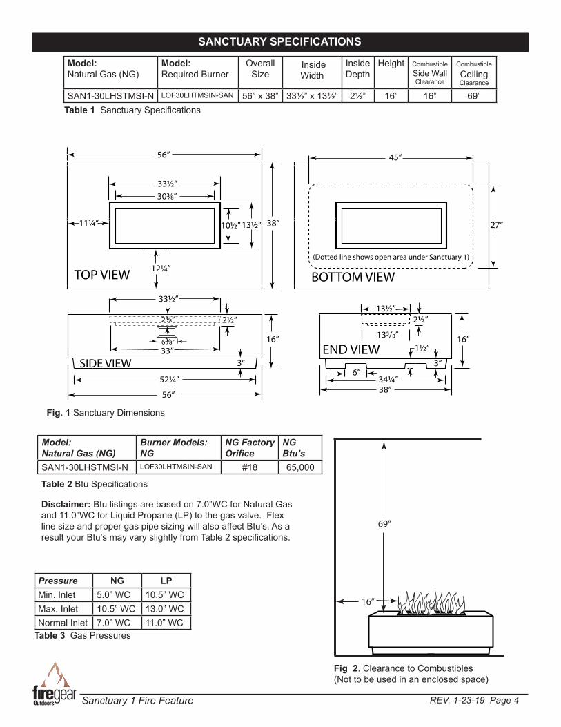
SANCTUARY SPECIFICATIONS
Table 1 Sanctuary Specifications
Fig 2. Clearance to Combustibles (Not to be used in an enclosed space)
Model:Natural Gas (NG)
Burner Models:NG
NG Factory Orifice
NG Btu’s
SAN1-30LHSTMSI-N LOF30LHTMSIN-SAN #18 65,000
Table 2 Btu Specifications
Model:Natural Gas (NG)
Model:Required Burner
Overall Size
InsideWidth
Inside Depth
Height CombustibleSide Wall Clearance
Combustible
CeilingClearance
SAN1-30LHSTMSI-N LOF30LHTMSIN-SAN 56” x 38” 33½” x 13½” 2½” 16” 16” 69”
Disclaimer: Btu listings are based on 7.0”WC for Natural Gas and 11.0”WC for Liquid Propane (LP) to the gas valve. Flex line size and proper gas pipe sizing will also affect Btu’s. As a result your Btu’s may vary slightly from Table 2 specifications.
Pressure NG LPMin. Inlet 5.0” WC 10.5” WCMax. Inlet 10.5” WC 13.0” WCNormal Inlet 7.0” WC 11.0” WC
Table 3 Gas Pressures
Fig. 1 Sanctuary Dimensions
69”
16”
2½”
33”
33½”
16”
56”
52¼”
12¼”
11¼”
303⁄8”
56”
38”10½” 13½”
3”
38”34¼”
16”135/8”
6”
1½”
3”
TOP VIEW
SIDE VIEWEND VIEW
33½”
2½”13½”
63⁄8”
23⁄8”
45”
27”
BOTTOM VIEW
(Dotted line shows open area under Sanctuary 1)
REV. 1-23-19 Page 5Sanctuary 1 Fire Feature
WARNING: Proper clearances from combustible materials must be maintained from all sides, top and bottom of this appliance. Use the specifications listed on page 4 for proper clearance to combustibles.
PREPARING A LOCATION FOR FIRE FEATURE
IMPORTANTInstallation of Natural or LP gas should be done by a qualified installer, service agency or gas supplier.The appliance and its manual shutoff valve must be disconnected from the gas supply piping system during any pressure testing of the system at test pressure testing of the system at test pressures in excess of ½” psig (3.5kPa).This appliance must be isolated from the gas supply piping system by closing its manual shutoff valve during any pressure testing of the gas supply piping system at test pressures equal to or less than ½” psig (3.5kPa)
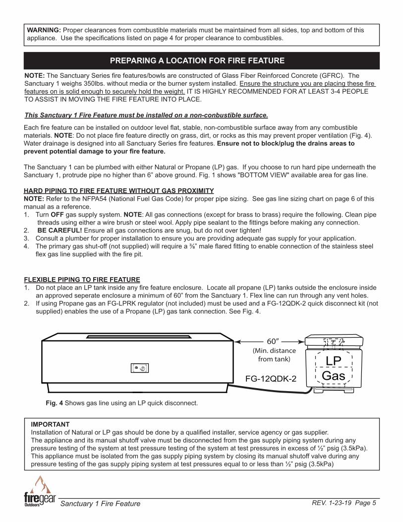
Each fire feature can be installed on outdoor level flat, stable, non-combustible surface away from any combustible materials. NOTE: Do not place fire feature directly on grass, dirt, or rocks as this may prevent proper ventilation (Fig. 4). Water drainage is designed into all Sanctuary Series fire features. Ensure not to block/plug the drains areas to prevent potential damage to your fire feature.
The Sanctuary 1 can be plumbed with either Natural or Propane (LP) gas. If you choose to run hard pipe underneath the Sanctuary 1, protrude pipe no higher than 6” above ground. Fig. 1 shows "BOTTOM VIEW" available area for gas line.
HARD PIPING TO FIRE FEATURE WITHOUT GAS PROXIMITYNOTE: Refer to the NFPA54 (National Fuel Gas Code) for proper pipe sizing. See gas line sizing chart on page 6 of this manual as a reference.1. Turn OFF gas supply system. NOTE: All gas connections (except for brass to brass) require the following. Clean pipe
threads using either a wire brush or steel wool. Apply pipe sealant to the fittings before making any connection. 2. BE CAREFUL! Ensure all gas connections are snug, but do not over tighten!3. Consult a plumber for proper installation to ensure you are providing adequate gas supply for your application.4. The primary gas shut-off (not supplied) will require a ⅜” male flared fitting to enable connection of the stainless steel
flex gas line supplied with the fire pit.
NOTE: The Sanctuary Series fire features/bowls are constructed of Glass Fiber Reinforced Concrete (GFRC). The Sanctuary 1 weighs 350lbs. without media or the burner system installed. Ensure the structure you are placing these fire features on is solid enough to securely hold the weight. IT IS HIGHLY RECOMMENDED FOR AT LEAST 3-4 PEOPLE TO ASSIST IN MOVING THE FIRE FEATURE INTO PLACE.
This Sanctuary 1 Fire Feature must be installed on a non-conbustible surface.
LPGasFG-12QDK-2
OFF
OFF
ON
OFF
LOW
HI
(Min. distance from tank)
60”
Fig. 4 Shows gas line using an LP quick disconnect.
FLEXIBLE PIPING TO FIRE FEATURE1. Do not place an LP tank inside any fire feature enclosure. Locate all propane (LP) tanks outside the enclosure inside
an approved seperate enclosure a minimum of 60” from the Sanctuary 1. Flex line can run through any vent holes.2. If using Propane gas an FG-LPRK regulator (not included) must be used and a FG-12QDK-2 quick disconnect kit (not
supplied) enables the use of a Propane (LP) gas tank connection. See Fig. 4.
REV. 1-23-19 Page 6Sanctuary 1 Fire Feature
REFERENCEGAS PIPE SIZING
Length of Pipe in Feet 1/2” 3/4” 1” 1 - 1/4” 1 - 1/2” 2” 2 - 2 1/2” 3” 4”
10 275 567 1071 2205 3307 6221 10140 17990 35710
20 189 393 732 1496 2299 4331 7046 12510 25520
30 152 315 590 1212 1858 3465 5695 10110 20620
40 129 267 504 1039 1559 2992 4778 8481 17300
50 114 237 448 913 1417 2646 4343 7708 15730
60 103 217 409 834 1275 2394 3908 6936 14150
70 89 185 346 724 1086 2047 3329 5908 12050
80 78 162 307 630 976 1811 2991 5309 10830
90 69 146 275 567 866 1606 2654 4711 9613
100 63 132 252 511 787 1496 2412 4281 8736
125 54 112 209 439 665 1282 2083 3618 7382
150 48 100 185 390 590 1138 1808 3210 6549
175 43 90 168 353 534 1030 1637 2905 5927
200 40 83 155 325 491 947 1505 2671 5450
300 37 77 144 303 458 887 1404 2492 5084
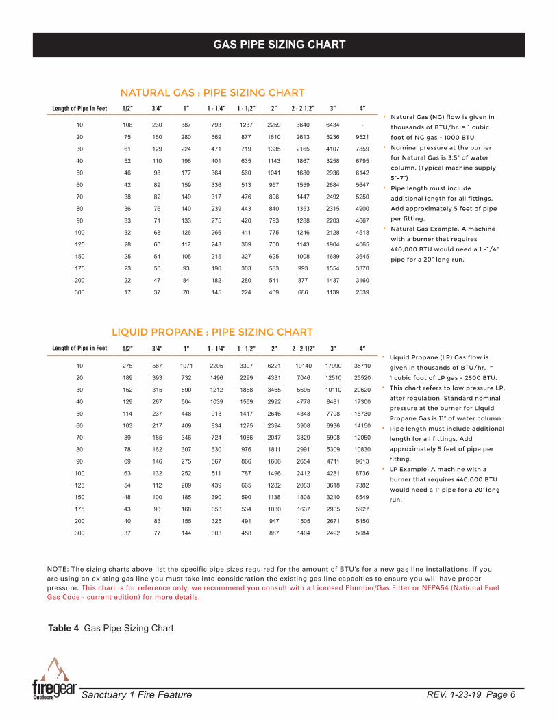
NATURAL GAS : PIPE SIZING CHART
• Natural Gas (NG) flow is given in
thousands of BTU/hr. = 1 cubic
foot of NG gas - 1000 BTU
• Nominal pressure at the burner
for Natural Gas is 3.5” of water
column. (Typical machine supply
5”-7”)
• Pipe length must include
additional length for all fittings.
Add approximately 5 feet of pipe
per fitting.
• Natural Gas Example: A machine
with a burner that requires
440,000 BTU would need a 1 -1/4”
pipe for a 20” long run.
LIQUID PROPANE : PIPE SIZING CHART
NOTE: The sizing charts above list the specific pipe sizes required for the amount of BTU’s for a new gas line installations. If you are using an existing gas line you must take into consideration the existing gas line capacities to ensure you will have proper pressure. This chart is for reference only, we recommend you consult with a Licensed Plumber/Gas Fitter or NFPA54 (National Fuel Gas Code - current edition) for more details.
Length of Pipe in Feet 1/2” 3/4” 1” 1 - 1/4” 1 - 1/2” 2” 2 - 2 1/2” 3” 4”
10 108 230 387 793 1237 2259 3640 6434 -
20 75 160 280 569 877 1610 2613 5236 9521
30 61 129 224 471 719 1335 2165 4107 7859
40 52 110 196 401 635 1143 1867 3258 6795
50 46 98 177 364 560 1041 1680 2936 6142
60 42 89 159 336 513 957 1559 2684 5647
70 38 82 149 317 476 896 1447 2492 5250
80 36 76 140 239 443 840 1353 2315 4900
90 33 71 133 275 420 793 1288 2203 4667
100 32 68 126 266 411 775 1246 2128 4518
125 28 60 117 243 369 700 1143 1904 4065
150 25 54 105 215 327 625 1008 1689 3645
175 23 50 93 196 303 583 993 1554 3370
200 22 47 84 182 280 541 877 1437 3160
300 17 37 70 145 224 439 686 1139 2539
• Liquid Propane (LP) Gas flow is
given in thousands of BTU/hr. =
1 cubic foot of LP gas - 2500 BTU.
• This chart refers to low pressure LP,
after regulation, Standard nominal
pressure at the burner for Liquid
Propane Gas is 11” of water column.
• Pipe length must include additional
length for all fittings. Add
approximately 5 feet of pipe per
fitting.
• LP Example: A machine with a
burner that requires 440,000 BTU
would need a 1” pipe for a 20’ long
run.
GAS PIPE SIZING CHART
Table 4 Gas Pipe Sizing Chart
REV. 1-23-19 Page 7Sanctuary 1 Fire Feature
REQUIREMENTS1. Only non-combustible materials should come in direct contact with any part of the fire feature. If the area underneath should
is a flat level combustible surface according to the clearances specified in this manual on page 5.
2. Refer to the NFPA54 (National Fuel Gas Code) for proper pipe sizing. See Table 4 on page 6.3. Determine the model fire feature you are preparing to install (Refer to page 4).4. Follow the local code requirements for the gas type being used. This fire feature should be installed in accordance
with local codes and ordinances or in the absence of local codes, with the latest National Fuel Gas Code, ANSI Z223.1 NFPA54 or CSA B149.1, Natural and Propane Installation Code in Canada.
5. Fire features create high temperatures, it is very important to have any combustibles at a safe distance. 6. NOTICE: Proper ventilation is built into the concrete fire feature. Do not bury or enclose or conceal the
bottom of the fire feature into earth, other type media that could block ventilation necessary for this product.7. These fire features are designed for outdoor use only. Not approved for any indoor use. 8. This fire feature is designed to have lava rock or glass media completely covering the burner, so that the burner is not
visible. Do not cover more than 1” above the top of the covered burner. When purchasing lava rock us minimum of 1 to 2-inch diameter as a base to fill the burner pan. DO NOT COVER THE PILOT HOOD WITH ANY ROCK OR MEDIA.
9. Gas lines and fittings must be installed in to the non-combustible structure. All gas connections must be leak tested before installation of the fire feature. Soapy water leak detection is required before regular use of the fire feature.
10. Do not use material that will absorb moisture over time and will not release this moisture quickly. Moisture can boil in this material and can rapidly break apart and cause damage or personal injury.
11. Never leave any other combustible material on top of the fire feature. This could cause unsafe operation of this system and damage to the component that will not be covered under our warranty.
INSTALLATION REQUIREMENTS OF FIRE FEATURE
SANCTUARY 1 PREPARATION
HIGH ELEVATION INSTALLATIONThis appliance is listed for elevations from 0- 4500 feet in Canada and the U.S. If elevation exceeds 4500 feet it may be necessary to decrease the input rating by changing the existing burner orifice to a smaller size. Input should be reduced 4% for each 1000 feet beyond the 4500 feet above sea level. Check with your local gas utility for assistance in determining the proper orifice in your location. In some cases the heating value may already be reduced and downsizing the orifice may not be necessary. Refer to NFPA54 Table E.1.1(d) for high altitude orifice sizing.
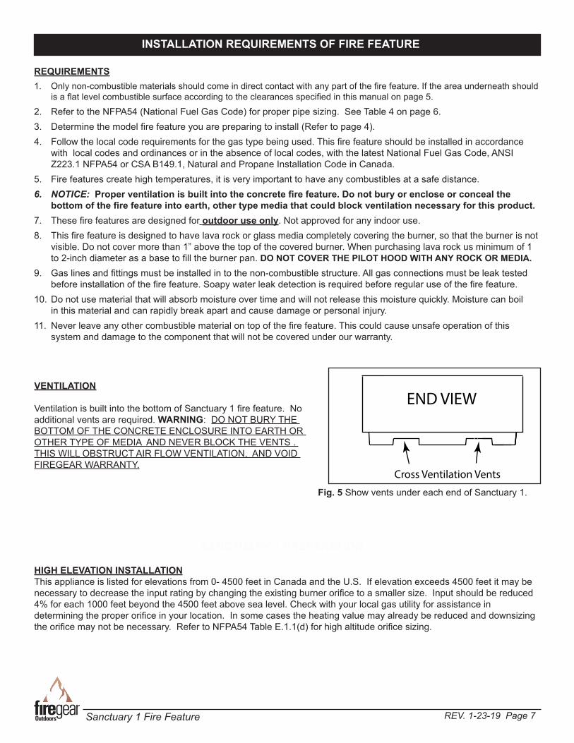
VENTILATION
Ventilation is built into the bottom of Sanctuary 1 fire feature. No additional vents are required. WARNING: DO NOT BURY THE BOTTOM OF THE CONCRETE ENCLOSURE INTO EARTH OR OTHER TYPE OF MEDIA AND NEVER BLOCK THE VENTS . THIS WILL OBSTRUCT AIR FLOW VENTILATION, AND VOID FIREGEAR WARRANTY.
END VIEW
Cross Ventilation Vents
Fig. 5 Show vents under each end of Sanctuary 1.
REV. 1-23-19 Page 8Sanctuary 1 Fire Feature
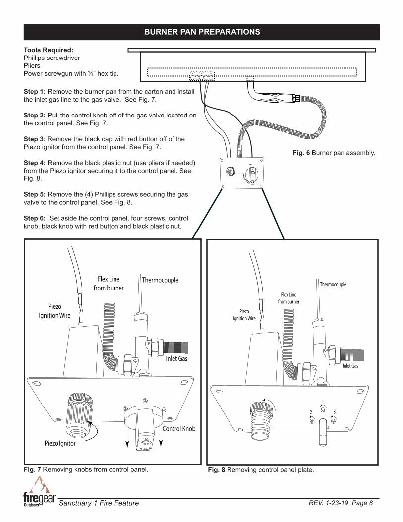
BURNER PAN PREPARATIONS
O F FO N
Inlet Gas
ThermocoupleFlex Line from burner
Piezo Ignition Wire
Piezo Ignitor
Control Knob
OFF
OFF
ON
OFF
LOW
Step 1: Remove the burner pan from the carton and install the inlet gas line to the gas valve. See Fig. 7.
Step 2: Pull the control knob off of the gas valve located on the control panel. See Fig. 7.
Step 3: Remove the black cap with red button off of the Piezo ignitor from the control panel. See Fig. 7.
Step 4: Remove the black plastic nut (use pliers if needed)from the Piezo ignitor securing it to the control panel. See Fig. 8.
Step 5: Remove the (4) Phillips screws securing the gas valve to the control panel. See Fig. 8.
Step 6: Set aside the control panel, four screws, control knob, black knob with red button and black plastic nut.
Fig. 7 Removing knobs from control panel.
Inlet Gas
Thermocouple
Flex Line from burner
Piezo Ignition Wire
1
2 3
4
Fig. 8 Removing control panel plate.
Fig. 6 Burner pan assembly.
Tools Required:Phillips screwdriverPliersPower screwgun with ¼” hex tip.
REV. 1-23-19 Page 9Sanctuary 1 Fire Feature
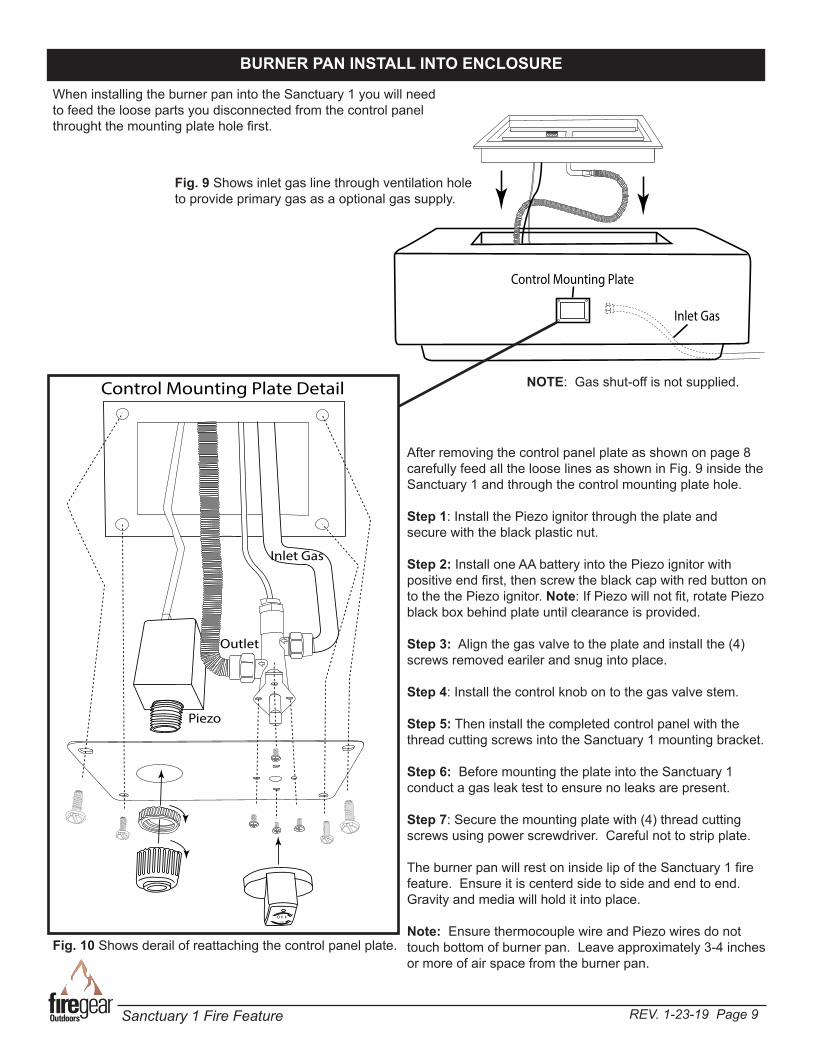
NOTE: Gas shut-off is not supplied.
BURNER PAN INSTALL INTO ENCLOSURE
When installing the burner pan into the Sanctuary 1 you will need to feed the loose parts you disconnected from the control panel throught the mounting plate hole first.
Control Mounting Plate
Inlet Gas
O F FO N
Piezo
Control Mounting Plate Detail
Inlet Gas
Outlet
Fig. 9 Shows inlet gas line through ventilation hole to provide primary gas as a optional gas supply.
After removing the control panel plate as shown on page 8 carefully feed all the loose lines as shown in Fig. 9 inside the Sanctuary 1 and through the control mounting plate hole.
Step 1: Install the Piezo ignitor through the plate and secure with the black plastic nut.
Step 2: Install one AA battery into the Piezo ignitor with positive end first, then screw the black cap with red button on to the the Piezo ignitor. Note: If Piezo will not fit, rotate Piezo black box behind plate until clearance is provided.
Step 3: Align the gas valve to the plate and install the (4) screws removed eariler and snug into place.
Step 4: Install the control knob on to the gas valve stem.
Step 5: Then install the completed control panel with the thread cutting screws into the Sanctuary 1 mounting bracket.
Step 6: Before mounting the plate into the Sanctuary 1 conduct a gas leak test to ensure no leaks are present.
Step 7: Secure the mounting plate with (4) thread cutting screws using power screwdriver. Careful not to strip plate.
The burner pan will rest on inside lip of the Sanctuary 1 fire feature. Ensure it is centerd side to side and end to end. Gravity and media will hold it into place.
Note: Ensure thermocouple wire and Piezo wires do not touch bottom of burner pan. Leave approximately 3-4 inches or more of air space from the burner pan.
Fig. 10 Shows derail of reattaching the control panel plate.
REV. 1-23-19 Page 10Sanctuary 1 Fire Feature
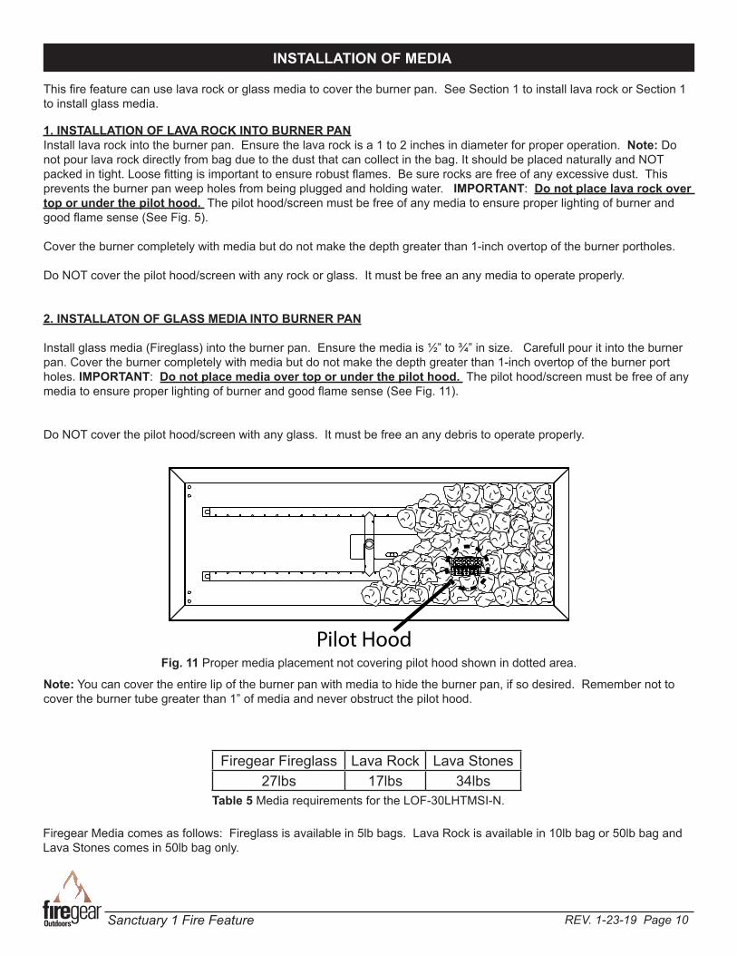
1. INSTALLATION OF LAVA ROCK INTO BURNER PANInstall lava rock into the burner pan. Ensure the lava rock is a 1 to 2 inches in diameter for proper operation. Note: Do not pour lava rock directly from bag due to the dust that can collect in the bag. It should be placed naturally and NOT packed in tight. Loose fitting is important to ensure robust flames. Be sure rocks are free of any excessive dust. This prevents the burner pan weep holes from being plugged and holding water. IMPORTANT: Do not place lava rock over top or under the pilot hood. The pilot hood/screen must be free of any media to ensure proper lighting of burner and good flame sense (See Fig. 5).
Cover the burner completely with media but do not make the depth greater than 1-inch overtop of the burner portholes.
Do NOT cover the pilot hood/screen with any rock or glass. It must be free an any media to operate properly.
2. INSTALLATON OF GLASS MEDIA INTO BURNER PAN
Install glass media (Fireglass) into the burner pan. Ensure the media is ½” to ¾” in size. Carefull pour it into the burner pan. Cover the burner completely with media but do not make the depth greater than 1-inch overtop of the burner port holes. IMPORTANT: Do not place media over top or under the pilot hood. The pilot hood/screen must be free of any media to ensure proper lighting of burner and good flame sense (See Fig. 11).
Do NOT cover the pilot hood/screen with any glass. It must be free an any debris to operate properly.
Fig. 11 Proper media placement not covering pilot hood shown in dotted area.
INSTALLATION OF MEDIA
Pilot Hood
Firegear Media comes as follows: Fireglass is available in 5lb bags. Lava Rock is available in 10lb bag or 50lb bag and Lava Stones comes in 50lb bag only.
Firegear Fireglass Lava Rock Lava Stones27lbs 17lbs 34lbs
Table 5 Media requirements for the LOF-30LHTMSI-N.
Note: You can cover the entire lip of the burner pan with media to hide the burner pan, if so desired. Remember not to cover the burner tube greater than 1” of media and never obstruct the pilot hood.
This fire feature can use lava rock or glass media to cover the burner pan. See Section 1 to install lava rock or Section 1 to install glass media.
REV. 1-23-19 Page 11Sanctuary 1 Fire Feature
CAUTION: Children and adults should be alerted to the hazards on high surface temperatures and should stay away to avoid burns or clothing ignition. Young children should be carefully supervised when they are in the area of the appliance.
WARNING: Do not use this appliance if any part has been under water. Immediately call a qualified service technician to inspect the appliance and to replace any part of control system and any gas control, which has been under water.
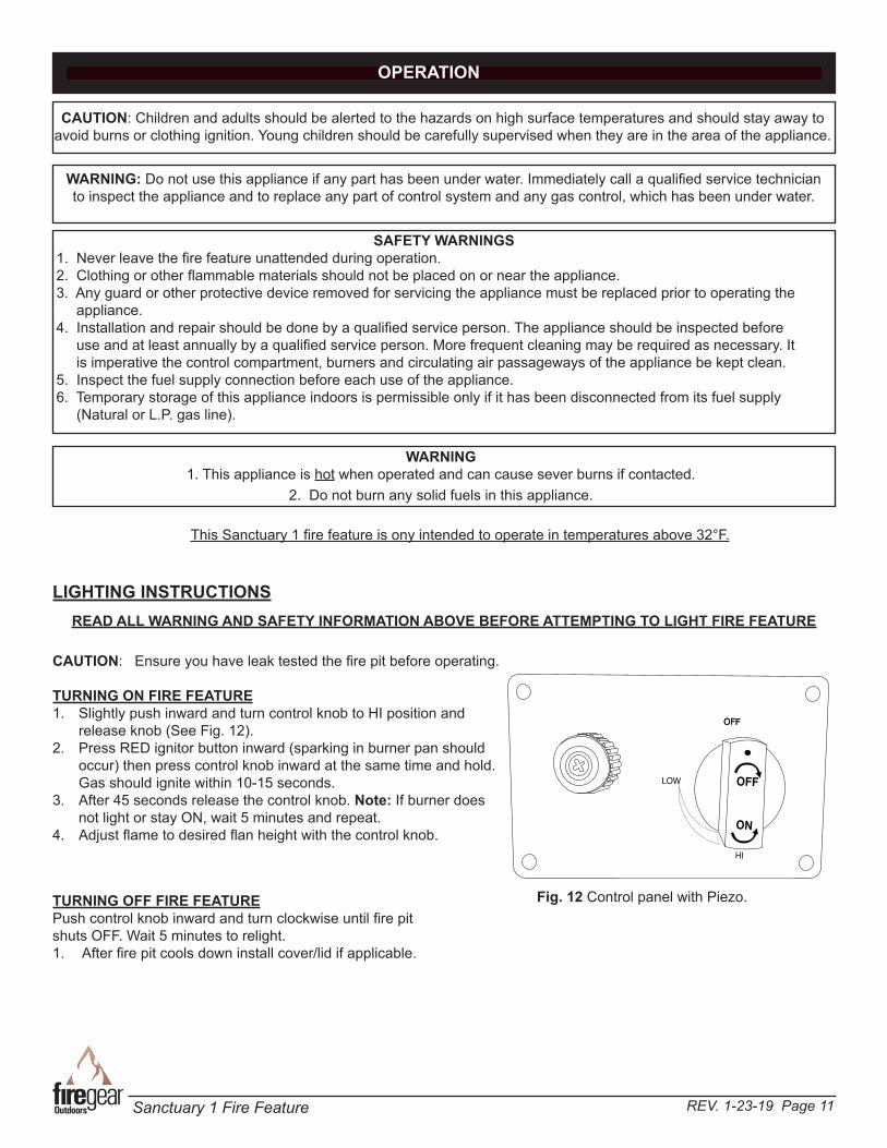
OPERATION
SAFETY WARNINGS 1. Never leave the fire feature unattended during operation. 2. Clothing or other flammable materials should not be placed on or near the appliance. 3. Any guard or other protective device removed for servicing the appliance must be replaced prior to operating the appliance. 4. Installation and repair should be done by a qualified service person. The appliance should be inspected before use and at least annually by a qualified service person. More frequent cleaning may be required as necessary. It is imperative the control compartment, burners and circulating air passageways of the appliance be kept clean. 5. Inspect the fuel supply connection before each use of the appliance. 6. Temporary storage of this appliance indoors is permissible only if it has been disconnected from its fuel supply (Natural or L.P. gas line).
WARNING1. This appliance is hot when operated and can cause sever burns if contacted.
2. Do not burn any solid fuels in this appliance.
LIGHTING INSTRUCTIONSREAD ALL WARNING AND SAFETY INFORMATION ABOVE BEFORE ATTEMPTING TO LIGHT FIRE FEATURE
Fig. 12 Control panel with Piezo.
CAUTION: Ensure you have leak tested the fire pit before operating.
TURNING ON FIRE FEATURE1. Slightly push inward and turn control knob to HI position and
release knob (See Fig. 12).2. Press RED ignitor button inward (sparking in burner pan should
occur) then press control knob inward at the same time and hold. Gas should ignite within 10-15 seconds.
3. After 45 seconds release the control knob. Note: If burner does not light or stay ON, wait 5 minutes and repeat.
4. Adjust flame to desired flan height with the control knob.
TURNING OFF FIRE FEATUREPush control knob inward and turn clockwise until fire pit shuts OFF. Wait 5 minutes to relight.1. After fire pit cools down install cover/lid if applicable.
OFF
OFF
ON
OFF
LOW
HI
This Sanctuary 1 fire feature is ony intended to operate in temperatures above 32°F.
REV. 1-23-19 Page 12Sanctuary 1 Fire Feature
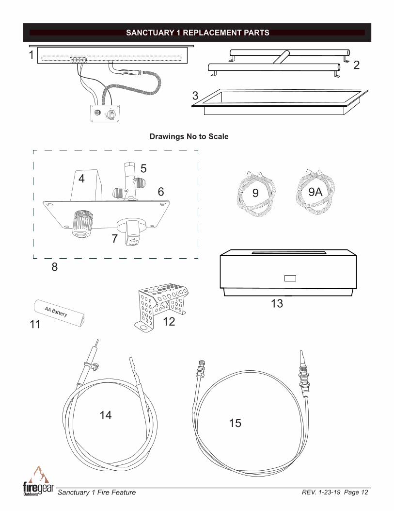
SANCTUARY 1 REPLACEMENT PARTS
12
4
3
Drawings No to Scale
6
O F FO N
OFF
OFF
ON
OFF
LOW
15
12AA Battery
5
7
9
11
13
14
8
9A

REV. 1-23-19 Page 13Sanctuary 1 Fire Feature
1 30” Complete H-burner assembly 1 LOF-30LHTMSI-N2 30” H- Burner only 1 FG-H-30SS3 30” H-Burner pan only 1 PAN-SS3010L4 Spark Ignitor Assembly (includes items # 14) 1 FG-SPARK-IGN5 Manual gas valve 1 FG-GASVALVE-16 Control panel plate only 1 FG-CONTROL-FP7 Gas control knob only 1 FG-CONTROL-KNOB8 Control panel (includes items # 4, 5, 6, 7,11, 14, 15) 1 FG-CONTROLPANEL9 Flex line (⅜” OD (¼” ID) with ⅜” flare nuts) 28” long 1 T100-9898-289A Flex line (⅜” OD (¼” ID) with ⅜” flare nuts) 46” long 1 T100-9898-4610 #8-18 x ½” Stainless Hex Screw (used with mounting plate) 4 SAN-CP-SCREWS11 AA battery 1 BATTAA12 Pilot Hood 1 FG-IGNITION-HOOD13 Sanctuary 1 (56” x 38” x 16” rectangular enclosure) 1 SANCTUARY114 Ignitor - Ignitor & wire 1 FG-IGNITORWIRE15 Thermocouple only 1 FG-TC-116 LP Conversion kit for (for all 30” & 36” models) not shown 1 LOF-BO-LP40
Item Description Qty. Part Number
SANCTUARY 1 REPLACEMENT PARTS LIST
TROUBLE SHOOTING
Symptom Remedy Fire pit won’t light 1. Bleed gas line. 3. Ensure all gas supply lines are turned ON. 4. Ensure there is not too much media overtop of burner; it can inhibit gas from flowing.
Low Flame 1. Ensure the base media is at least 1-inch in diameter and top media is no more than 1-inch over top of burner. 2. Ensure all shut-off valves and valve is fully open. 3. Check for spider webs inside burner orifice.
Water in my fire pit 1. Excess dust/sand material from media may be blocking the weep holes to relieve water. Remove all media and unplug weep holes. Clean or install new media free of dust and dirt. 2. Ensure fire pit enclosure has proper drainage for water and proper ventilation to dry out. 3. Recommend to purchase a cover/lid to keep excessive water out of the fire pit.
Whistling Noises 1. STOP - TURN OFF GAS SUPPLY: Check for loose fittings and gas leaks. 2. Check media to ensure it is not too tightly packed around the burner tube. 3. Ensure a non-whistling flex connector is being used. Fire pit won’t stay lit 1. Check alignment of thermocouple over rainshield on page 10, Fig. 7. 2. Ensure thermocouple is not screwed too tight into gas valve. It should be finger tight plus a quarter turn with a wrench. 3. Ensure thermocouple is clean and free of any debris. Excessive soot can be an issue.

REV. 1-23-19 Page 14Sanctuary 1 Fire Feature
BURNER MAINTENANCE
1. These fire features should be inspected and cleaned before initial use at least annually by a qualified field service person.
2. Any component that is found faulty must be replaced with an approved component.3. Any tampering or modifying with the fire feature is dangerous and voids all warranties.4. During winter months in cold climates and various seasons operation the fire feature may be affected by weather
conditions. It is recommended to use a cover/lid overtop of your fire feature to protect it from humid/rainy weather conditions when not in use. Heavy rains/downpours could affect the fire feature operation if not covered; if this
occurs ensure you allow the fire feature time to dry out before attempting to operate. NOTE: If a combustible type cover is used over the fire feature when not in use be sure to remove it before operation to prevent a severe safety hazard.5. Over time stainless steel parts can discolor when heated, usually a golden or brown hue. This discoloration is normal and does not affect the performance of the appliance.6. It is imperative to keep the control panel and burner and vent air passages clean and free.7. Periodically, check the hose connecting the Propane gas tank to ensure it is not cracked or damaged in any way.8. Inspect and clean burners periodically checking for spiders and insects that can nest and block burners or airflow to
the enclosure.9. When the fire feature is not in use, turn OFF the gas supply at the source.
GFRC MAINTENANCE
• To care for your GFRC (Glass Fiber Reinforced Concrete) product, please utilize careful judgment. It is a durable and forgiving material, but that does not mean you can expose it to harsh chemicals or mechanical cleaning methods which could damage the outer finish. Instead, we recommend you use a soft brush with natural or synthetic bristles, utilizing very light pressure and water to clean the concrete items.
• Concrete by nature, is a porous material and therefore, susceptible to staining. In addition, over time it will age some-times changing the color just as the common household driveway will. Sealing of products is always recommended to protect the original appearance. Our products are sealed prior to shipment but the continued care and resealing of the product will be needed every 4-5 years to protect the appearance.
• With a concrete sealant, your concrete will look great and natural for many occasions. Prolonged contact with overly
acidic, heavily pigmented or alkali substances should be avoided. We recommend cleaning any spills as quickly as possible. Take caution against use of caustic acids to clean or resurface concrete products. Such caustic acids have historically been used to clean pools, sidewalks or other porous concrete surfaces. These acids will etch the surface and change the structure of the concrete at the surface level. Our concrete is made to have a denser and cleaner look; such etching from caustic acids will change that clean, smooth finish.
• DO NOT USE HARSH ABRASIVE CLEANERS, ACIDS, PIGMENTED CLEANERS OF ALKALI SUBSTANCES ON CONCRETE PRODUCTS. While for many applications it MAY be safe to use muriatic acid/hydrochloric acid or sulfuric acid, or other strong chemicals to clean concrete, DO NOT use these cleaners to clean the items we sell made from reinforced concrete. This WILL damage the beautiful finish on the outside of the concrete. Such chemical cleaners are not applicable for use on this type of material.
• Additionally, we do not recommend using high-pressure cleaning, as this could remove the sealed finish. Using a
garden hose will be enough pressure to clean the concrete. For normal spills, a quick wipe up and gentle “scrub” with a cotton cloth or similar, should be enough to clean. For stains, which contain dark colors or have been sitting for an extended period of time, you can use a mild soap. Under extreme cleaning needs, you can use a standard mild household chlorine bleach, available in most retail stores, diluted to a very weak mixture of about 1/4 cup bleach to 1 gallon of water. Use this mixture over the entire surface you wish to clean, to ensure even cleaning. Only do this as a last resort as it could change the appearance of the product.
• Please also note that fissures (hairline cracks) can appear on the surface due to age and/or exposure to the atmospheric conditions. These commonly don’t have an effect on durability and do not compromise the structural integrity of the product.
REV. 1-23-19 Page 15Sanctuary 1 Fire Feature
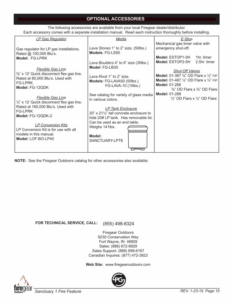
OPTIONAL ACCESSORIES
The following accessories are available from your local Firegear dealer/distributor. Each accessory comes with a separate installation manual. Read each instruction thoroughly before installing.
LP Gas Regulator
Gas regulator for LP gas installations. Rated @ 100,000 Btu’s.Model: FG-LPRK
Flexible Gas Line⅜” x 12’ Quick disconnect flex gas line. Rated at 80,000 Btu’s. Used withFG-LPRK Model: FG-12QDK
Flexible Gas Line½” x 12’ Quick disconnect flex gas line.Rated at 160,000 Btu’s. Used with FG-LPRK Model: FG-12QDK-2
LP Conversion KitsLP Conversion Kit is for use with all models in this manual. Model: LOF-BO-LP40
Media
Lava Stones 1” to 2” size. (50lbs.)Models: FG-LS50
Lava Boulders 4” to 6” size (30lbs.) Model: FG-LB30
Lava Rock 1” to 2” size.Models: FG-LAVA50 (50lbs.) FG-LAVA-10 (10lbs.)
See catalog for variety of glass media in various colors.
LP Tank Enclosure20” x 21½” tall concrete enclosure to hide 20# LP tank. Has removable lid. Can be used as an end table. Weighs 141lbs.
Model:SANCTUARY-LPTE
E-StopMechanical gas timer valve with emergency shut-off.
Model: ESTOP1-0H 1hr. timerModel: ESTOP2-5H 2.5hr. timer
Shut-Off ValvesModel: 01-387 ⅜” OD Flare x ½” FIPModel: 01-487 ½” OD Flare x ½” FIPModel: 01-266 ⅜” OD Flare x ⅜” OD FlareModel: 01-288 ½” OD Flare x ½” OD Flare
FOR TECHNICAL SERVICE, CALL: (855) 498-8324
NOTE: See the Firegear Outdoors catalog for other accessories also available.
Firegear Outdoors9230 Conservation WayFort Wayne, IN 46809Sales: (888) 672-8929
Sales Support: (888) 699-6167Canadian Inquires: (877) 472-3923
Web Site: www.firegearoutdoors.com
REV. 1-23-19 Page 16Sanctuary 1 Fire Feature
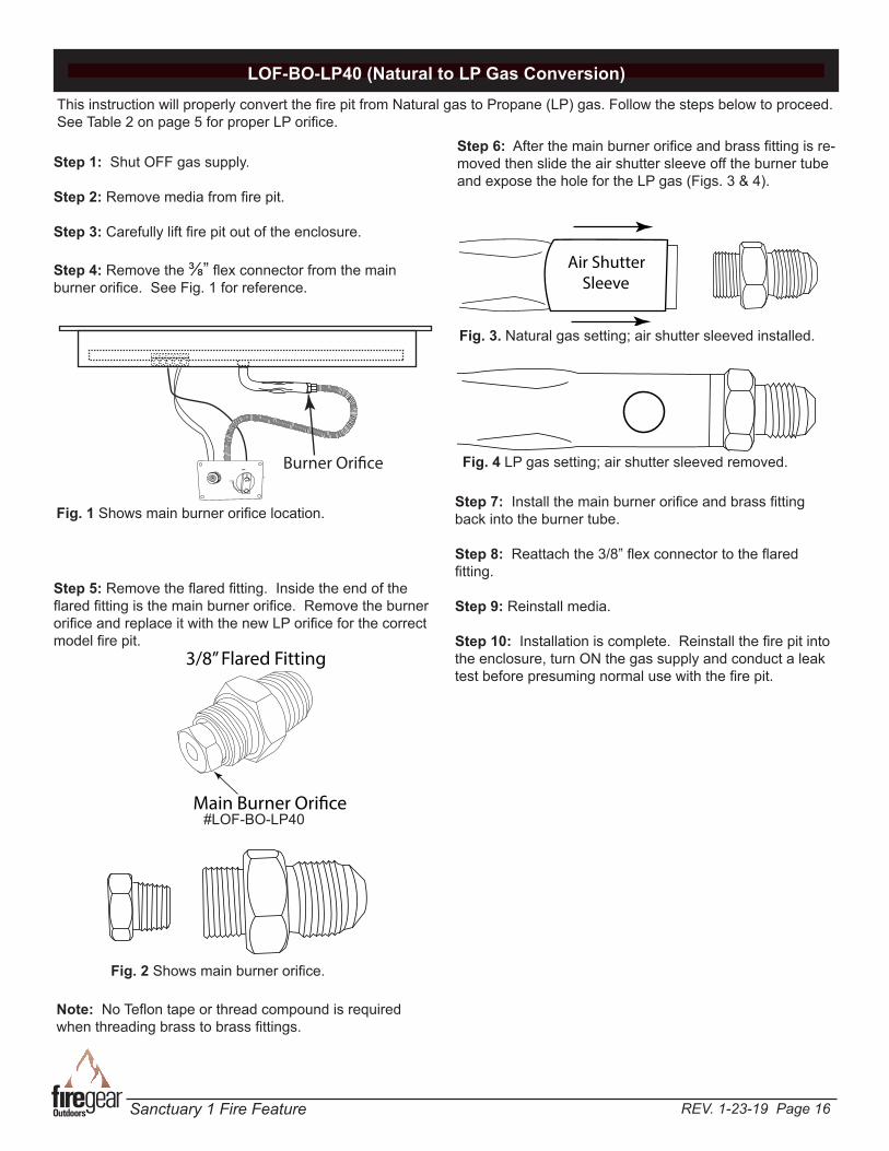
LOF-BO-LP40 (Natural to LP Gas Conversion)
Step 1: Shut OFF gas supply.
Step 2: Remove media from fire pit.
Step 3: Carefully lift fire pit out of the enclosure.
Step 4: Remove the ⅜” flex connector from the main burner orifice. See Fig. 1 for reference.
OFF
OFF
ON
OFF
LOW
Burner Ori�ce
Step 5: Remove the flared fitting. Inside the end of the flared fitting is the main burner orifice. Remove the burner orifice and replace it with the new LP orifice for the correct model fire pit.
3/8” Flared Fitting
Main Burner Ori�ce
This instruction will properly convert the fire pit from Natural gas to Propane (LP) gas. Follow the steps below to proceed. See Table 2 on page 5 for proper LP orifice.
Fig. 1 Shows main burner orifice location.
Air Shutter Sleeve
Step 6: After the main burner orifice and brass fitting is re-moved then slide the air shutter sleeve off the burner tube and expose the hole for the LP gas (Figs. 3 & 4).
Fig. 3. Natural gas setting; air shutter sleeved installed.
Fig. 2 Shows main burner orifice.
Fig. 4 LP gas setting; air shutter sleeved removed.
Note: No Teflon tape or thread compound is required when threading brass to brass fittings.
Step 7: Install the main burner orifice and brass fitting back into the burner tube.
Step 8: Reattach the 3/8” flex connector to the flared fitting.
Step 9: Reinstall media.
Step 10: Installation is complete. Reinstall the fire pit into the enclosure, turn ON the gas supply and conduct a leak test before presuming normal use with the fire pit.
#LOF-BO-LP40

REV. 1-23-19 Page 17Sanctuary 1 Fire Feature
Skytech Products Group (Firegear Outdoors) hereby warrants to the end user that products will be free from material and workmanship defects that prevent safe and correct operation of the product. The warranty commences from date of sale to the end user for the following period:
End User must provide a bill of sale, canceled check, or payment record from the end user to verify purchase date and to establish warranty period. This Limited Warranty shall be valid and limited to the original purchaser only.
WARNING Any modification to the product will void the warranty.
This Limited Warranty shall be limited to the repair and/or replacement of parts that have proven to be defective under normal use and service. Before returning any parts, contact our Technical Service Department for a Return Materials Authorization (RMA) number. All warranty claims must be made by the OEM / Distributor / Dealer account on behalf of the end user. You may contact Technical Service at (855) 498-8324.
All approved returned defects must be confirmed by our Technical Service Department. If the defect is confirmed and we approve the claim, we will replace such parts without charge. This warranty gives you specific legal rights, and you may also have other rights, which vary from state to state.
Travel, diagnostic cost, service labor to repair the defect and freight charges on warranty parts to and from the factory will be responsibility of the owner. We will not be responsible for labor charges and/or damage incurred in installation, repair, and replacement.
LIMITED WARRANTY
This Limited Warranty is voided if not assembled, installed and operated as intended. This Limited Warranty does not cover any defects due to accident, abuse, misuse, alteration, misapplication, vandalism, improper installation or improper maintenance or service, removal from the original location or re- installation into another location, or failure to perform normal and routine maintenance.
Damage due to severe weather conditions such as hail, hurricanes, earthquakes, tornadoes, discoloration due to over-heating, exposure to chemicals (including salt), either directly or in the atmosphere, or very high humidity, is not covered by this Limited Warranty.
There are no other express warranties except as set forth herein. For consumer applications, any applicable implied warranties of merchantability and fitness are limited induration to the period of coverage of this Limited Warranty. Some states do not allow limitation on how long an implied warranty lasts, so this limitation may not apply to you.
For Commercial applications, the liability of Firegear Outdoors is limited to the express terms of this warranty. We expressly disclaim any and all implied warranties, including any warranties of fitness for a particular purpose or merchantability.
We are not liable for any special, indirect or consequential damages. Our maximum liability is limited to the purchase price of the purchased products. Some states do not allow the exclusion or limitation of incidental or consequential damages, so this limitation or exclusions may not apply to you.
We do not authorize any person or company to assume for it any other obligation or liability in connection with the sale, installation, use, removal, return, or replacement of its equipment; and no such representations are binding.
Lava Rock and Lava Stones are not covered by warranty
CONSUMER/NON-COMMERCIAL APPLICATIONS:Stainless Steel Components 5 YearsGas Valve, Spark Igniter & Electronic Parts 2 YearsLog Sets 3 YearsGlass Windshields 5 YearsGlass Media 1 YearControls 5 YearsAnF Enclosures 5 YearsGFRC (Glass Fiber Reinforced Concrete) 1 Year
COMMERCIAL APPLICATIONS:Stainless Steel Components 1 YearGas Valve, Spark Igniter & Electronic Parts 1 YearLog Sets 1 YearGlass Windshields 1 YearGlass Media 1 YearControls 1 YearAnF Enclosures 1 YearGFRC (Glass Fiber Reinforced Concrete) 1 Year
Lava Rock and Lava Stones are not covered by warranty
A DIVISION OF SKYTECH PRODUCTS GROUP
REV. 6/18
REV. 1-23-19 Page 18Sanctuary 1 Fire Feature
Having problems getting your Firegear Outdoors fire pit to operate? Don’t leave the job site! We want to help! Call 855.498.8324
for Technical Support between the hours of 8:00AM to 5:00PM EST. Text photos to 260.255.5750 or e-mail photos to [email protected].
BEFORE YOU CALL WE WILL NEED THIS INFORMATION
1. Model Number: ___________________________
2. Serial Number: ___________________________
3. How long is the gas line run? Nat Gas ____ LP Gas ____
4. What size is gas line? _____
5. Inlet Gas Pressure: _____WC Manifold Gas Pressure: _____ WC
6. What type of media are you using? __________________
7. Review the troubleshooting section in the installation manual.
8. What are the symptoms? Please be prepared to explain.
9. Be prepared to send photos to us when on the phone.
10. Missing or damaged parts? Let us know ASAP or send photos.


![Telecommunication Products - Trendtek jointing pits.pdf · [01] UG2006 - P6 Pit UG2007 - P7 Pit UG2008 - P8 Pit UG2900 - P9 Pit UG2001 - P1 Pit UG2002 - P2 Pit UG2003 - P3 Pit UG2004](https://static.fdocuments.us/doc/165x107/5a7969077f8b9ab9308d3433/telecommunication-products-jointing-pitspdf01-ug2006-p6-pit-ug2007-p7-pit.jpg)