San Antonio Water System Standard Specifications … Antonio Water System Standard Specifications...
12
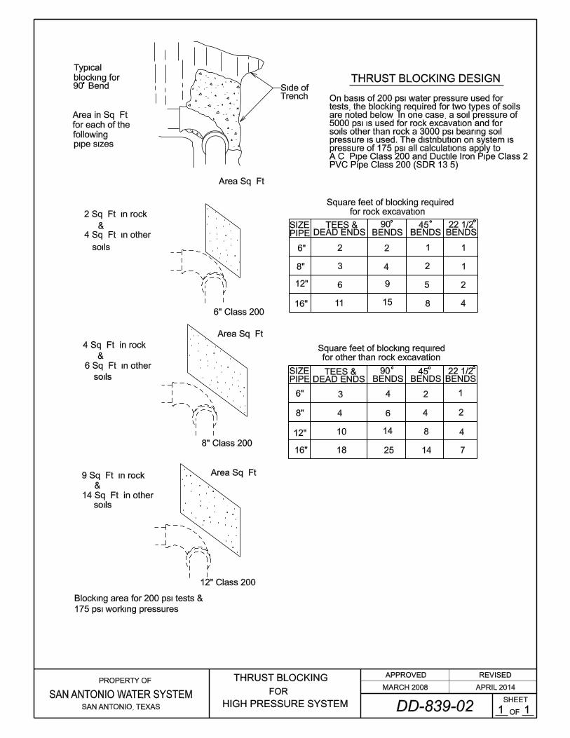
San Antonio Water System Standard Specifications for Construction 839-1 April 2014 ITEM NO. 839 ANCHORAGE/THRUST BLOCKING AND JOINT RESTRAINT 839.1 DESCRIPTION: This item shall consist of anchorage/thrust blocking installation and adjustment, in accordance with these specifications and as directed by the Engineer. Pipe restraint devices shall be installed according to the lengths prescribed herein or as noted in the contract documents, whichever is more restrictive. 839.2 MATERIALS: The materials for anchorage/thrust blocking installation shall conform to the appropriate specifications contained within the latest revision of SAWS Material Specifications. Pipe restraint devices shall conform to the latest revision of SAWS Material Specification Item Nos. 95-10 and 113-02. 839.3 CONSTRUCTION: Suitable anchorage/thrust blocking or joint restraint shall be provided at all of the following main locations: dead ends, plugs, caps, tees, crosses, valves, and bends, in accordance with the Standard Drawings DD-839 Series. All mechanical (joint) restraints shall be bidirectional. Anchor blocks shall be constructed solidly behind the fitting and symmetrical with the axis of resultant thrust, except where this is not possible as in the case of gravity anchorage for vertical bends. Special ties and anchor fittings may be utilized in conjunction with blocking when shown in the contract documents or as directed by the Engineer. All thrust blocking shall be a minimum of 3,000 psi concrete placed between solid ground and the fitting except as otherwise shown in the contract documents. The area of bearing in contact with solid ground shall be that shown in the contract documents or as directed by the Engineer. All thrust blocking placed in conjunction with mains and appurtenances constructed in Pressure Zones 9 through 16 shall be in accordance with Standard Drawings DD-839 Series. In all cases, the design of thrust blocking shall be of sufficient size to withstand an assumed soil lateral load bearing capacity of 3,000 psf, unless specified otherwise in the contract documents. When specifically requested by the Contractor and approved by the Engineer, the maximum soil lateral load bearing capacity that will be allowed for the design of thrust blocking shall be 5,000 psf. When soil lateral load bearing capacities of 4,000 psf or 5,000 psf are recorded for design of thrust blocks, copies of soil tests made for determining the lateral load bearing capacity of the subject soil shall be submitted to the Engineer for approval. The blocking shall be placed so that pipe and fitting joints will be accessible.
-
Upload
phungnguyet -
Category
Documents
-
view
217 -
download
4
Transcript of San Antonio Water System Standard Specifications … Antonio Water System Standard Specifications...

San Antonio Water System Standard Specifications for Construction
839-1 April 2014
ITEM NO. 839
ANCHORAGE/THRUST BLOCKING AND JOINT RESTRAINT
839.1 DESCRIPTION: This item shall consist of anchorage/thrust blocking installation
and adjustment, in accordance with these specifications and as directed by the
Engineer. Pipe restraint devices shall be installed according to the lengths
prescribed herein or as noted in the contract documents, whichever is more
restrictive.
839.2 MATERIALS: The materials for anchorage/thrust blocking installation shall
conform to the appropriate specifications contained within the latest revision of
SAWS Material Specifications. Pipe restraint devices shall conform to the latest
revision of SAWS Material Specification Item Nos. 95-10 and 113-02.
839.3 CONSTRUCTION: Suitable anchorage/thrust blocking or joint restraint shall be
provided at all of the following main locations: dead ends, plugs, caps, tees,
crosses, valves, and bends, in accordance with the Standard Drawings DD-839
Series. All mechanical (joint) restraints shall be bidirectional. Anchor blocks
shall be constructed solidly behind the fitting and symmetrical with the axis of
resultant thrust, except where this is not possible as in the case of gravity
anchorage for vertical bends. Special ties and anchor fittings may be utilized in
conjunction with blocking when shown in the contract documents or as directed
by the Engineer.
All thrust blocking shall be a minimum of 3,000 psi concrete placed between solid
ground and the fitting except as otherwise shown in the contract documents. The
area of bearing in contact with solid ground shall be that shown in the contract
documents or as directed by the Engineer.
All thrust blocking placed in conjunction with mains and appurtenances
constructed in Pressure Zones 9 through 16 shall be in accordance with Standard
Drawings DD-839 Series. In all cases, the design of thrust blocking shall be of
sufficient size to withstand an assumed soil lateral load bearing capacity of 3,000
psf, unless specified otherwise in the contract documents. When specifically
requested by the Contractor and approved by the Engineer, the maximum soil
lateral load bearing capacity that will be allowed for the design of thrust blocking
shall be 5,000 psf. When soil lateral load bearing capacities of 4,000 psf or 5,000
psf are recorded for design of thrust blocks, copies of soil tests made for
determining the lateral load bearing capacity of the subject soil shall be submitted
to the Engineer for approval.
The blocking shall be placed so that pipe and fitting joints will be accessible.

San Antonio Water System Standard Specifications for Construction
839-2 April 2014
Pipe polywrap shall be placed between the pipe or fitting and the concrete.
The reaction block on the unused branch of a fitting shall be poured separately
from the block across the back of the fitting. If they are poured simultaneously, a
rigid partition shall be placed between the blocks.
Valves 12 inches or larger in size shall be supported on a concrete pad extending
vertically from 12 inches below the bottom of the valve to the lower quarter point
of the hub and laterally from face to face of hubs and transversely from wall to
wall of the trench.
839.4 MEASUREMENT: Anchorage/Thrust Blocking or Joint Restraints are
considered subsidiary to the work and no separate payment will be made to the
Contractor for this work.
839.5 PAYMENT: Anchorage/Thrust Blocking or Joint Restraints are considered
subsidiary to the work and no separate payment will be made to the Contractor for
this work.
- End of Specification -

Sides of trench
Select Material
Select Material
Concrete blocking required for
all 12" & larger, except in
high pressure distribution system
where blocking is required for
all valves
SAN ANTONIO, TEXAS
PROPERTY OF
SAN ANTONIO WATER SYSTEMSHEET
OF
THRUST BLOCKS FOR
FITTINGS ( WATER ONLY )1 2
APPROVED REVISED
MARCH 2008 APRIL 2014
Pour base after
Hydrant has been placed
Hydrant Drain
ELEVATION
PLAN PLAN
ELEVATION

R.L. = RESTRAINED LENGTHS TO BEDETERMINED BY DESIGN ENGINEER
APRIL 2014JOINT RESTRAINTS FORFITTINGS (WATER ONLY)