SAMPLING PRINCIPLES, METHODS AND SELECTION OF...
32
SAMPLING PRINCIPLES, METHODS AND SELECTION OF SITES RER/1/013 Regional Training course ; Sacavém, Portugal, 02 –06 June, 2014
Transcript of SAMPLING PRINCIPLES, METHODS AND SELECTION OF...

SAMPLING PRINCIPLES, METHODS
AND SELECTION OF SITES
RER/1/013 Regional Training course ; Sacavém, Portugal, 02 –06 June, 2014

Aerosol Sampling
Aerosol sampling systems consists usually of:
1. An inlet (or pre-selector) which samples a certain aerosol fraction
2. A transport system (pipes etc.) in which the aerosol is transported
to instruments or collectors.
Particle losses can occur due to following processes:
a) sedimentation
b) impaction
c) diffusion
Inlets, Pre-Separators, and Transport Systems
RER/1/013 Regional Training course ; Sacavém, Portugal, 02 –06 June, 2014

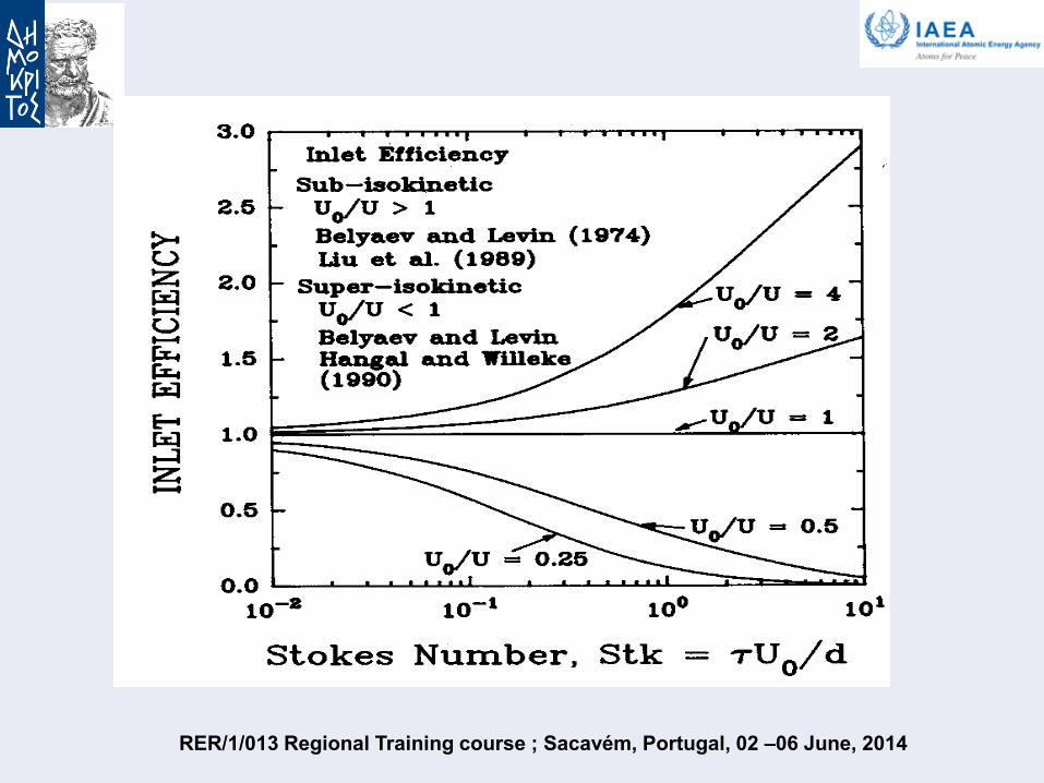
Inlets
Isokinetic inlet: The sampling velocity in the inlet tube is equal to
the wind velocity outside (U = U
0 ).
Isoaxial inlet: The direction of the inlet tube faces directly the
wind direction ( = 0).
The sampling efficiency changes for (U U
0) and ( 0) in
dependence of the Stokes number.
τ = Relaxation time
U0 = Wind velocity
d = tube diameter
The Stokes number is the ratio between the particle stopping
distance to characteristic dimensions of the flow profile.
The particle losses can be neglected for Stk < 0.01 and for 0.2 <
U/U0 < 5.
P P CD C2
18with
Stk U
d
0
RER/1/013 Regional Training course ; Sacavém, Portugal, 02 –06 June, 2014

Isoaxial Sampling ( = 0)
RER/1/013 Regional Training course ; Sacavém, Portugal, 02 –06 June, 2014

RER/1/013 Regional Training course ; Sacavém, Portugal, 02 –06 June, 2014

RER/1/013 Regional Training course ; Sacavém, Portugal, 02 –06 June, 2014
RER/1/013 Regional Training course ; Sacavém, Portugal, 02 –06 June, 2014

Anisoaxial Sampling ( 0)
RER/1/013 Regional Training course ; Sacavém, Portugal, 02 –06 June, 2014

RER/1/013 Regional Training course ; Sacavém, Portugal, 02 –06 June, 2014

RER/1/013 Regional Training course ; Sacavém, Portugal, 02 –06 June, 2014

RER/1/013 Regional Training course ; Sacavém, Portugal, 02 –06 June, 2014

Pre-Separators:
Devices based on inertia are usually used as pre-separators:
a) impactors
b) cyclones
Pre-separators are used to remove particles larger (or smaller) than a
certain size from the aerosol.
Impactors can be theoretically better described than all other types of
pre-separators.
Cyclones and other pre-separators must be calibrated to know their
behavior.
RER/1/013 Regional Training course ; Sacavém, Portugal, 02 –06 June, 2014

Low flow PM10 inlet:
Penetration efficiency curve RER/1/013 Regional Training course ; Sacavém, Portugal, 02 –06 June, 2014

Transport Systems:
Particle losses in transport systems can occur due to:
a) Inertia in bends (large particles)
b) Sedimentation in horizontal pipes (large particles)
c) Diffusion (small particles)
RER/1/013 Regional Training course ; Sacavém, Portugal, 02 –06 June, 2014

Recommendations:
For particles > 1 µm:
Pipes should be vertically orientated.
In cases when horizontal pipes cannot be avoided, the flow should be
high.
Strong bends should be avoided.
Highly turbulent flows causes increased inertial losses
For particles < 0.1 µm:
Pipes should be kept as short as possible.
The transport system should designed for a laminar flow with the
optimum Reynolds number of 2000.
Turbulent flows should be avoided, because of higher diffusional
particle losses.
RER/1/013 Regional Training course ; Sacavém, Portugal, 02 –06 June, 2014

General Sampling Considerations
Sample air should be brought into the laboratory through a
vertical stack with an inlet that is well above ground level.
For sites in level terrain, surrounded by no or low vegetation, a
height of 5-10 m above ground level is recommended.
Because gas analysers may have incompatible requirements, a
dedicated inlet stack may be required for the aerosol samples.
The size of the entrance configuration must be well designed to
provide a high inlet sampling efficiency for aerosol particles over
a wide range of wind speeds.
The sample flow should be laminar in the sample tube to avoid
additional losses of small particles due to diffusion and turbulent
inertial deposition. The ideal flow should have a Reynolds
number of about 2000.
RER/1/013 Regional Training course ; Sacavém, Portugal, 02 –06 June, 2014

The inlet material should consist of conductive and non corrosive
tubing material such as stainless-steel that are weather- and sunlight-
resistant.
In tropical regions, the sample air must be either dried or diluted by
particle-free dry air to avoid condensation in the sampling pipes.
The relative humidity should be kept below 40%.
Aerosol sampling equipment should be housed in a shelter that provides
a controlled laboratory environment (temperature 15-30°C).
General Sampling Considerations
RER/1/013 Regional Training course ; Sacavém, Portugal, 02 –06 June, 2014

Filter
An important task in aerosol technology is to remove particles from
the carrier gas they are suspended in utilizing filters.
Filters are used for as well gas cleaning as particle sampling (e.g.
chemical characterization).
Filters are especially used for sub-micron particles and for low
particles number concentrations.
Filters are characterized by their deposition efficiency E,
(alternatively the penetration P) and their pressure drop p .
N0 = number concentration up-stream of the filter
N1 = number concentration down-stream of the filter
P0 = pressure up-stream of the filter
P1 = pressure down-stream of the filter
0
10
N
NNE
EP 1
10 ppp
RER/1/013 Regional Training course ; Sacavém, Portugal, 02 –06 June, 2014

The "ideal filter" should have an deposition efficiency of E = 1 together
with a pressure p = 0.
Mechanisms for the deposition of particles on and/or inside filters are:
• Impaction
• Interception
• Diffusion
• Settling
• External forces (electrical forces)
These deposition mechanisms depend an the actual flow situation in the
vicinity and/or inside the filter as well as particle size and shape.
The actual flow situation is characterized in terms of the filter face velocity:
A
Vu
0
= aerosol volume flow rate
A = filter area
V
RER/1/013 Regional Training course ; Sacavém, Portugal, 02 –06 June, 2014

Particle deposition in filters is a function of particle size.
The deposition efficiency in filters always shows a minimum, i.e. a
penetration maximum.
The position of the deposition efficiency minimum on the particle
size axis depends on the filter itself.
The deposition efficiency is also a function of the actual filter
loading and consequently a function of time.
With increasing time, both deposition efficiency and pressure drop
increase.
The theoretical description of particle transport in filters is
complex.
The two most important types of filters are:
• fiber filters
• membrane filter RER/1/013 Regional Training course ; Sacavém, Portugal, 02 –06 June, 2014

Filter selection criteria include:
1. Mechanical stability
2. Chemical stability
3. Sampling efficiency
4. Flow resistance
5. Loading capacity
6. Blank values
7. Artifact formation
8. Compatibility with analytical protocols
9. Cost and availability
Filter media for atmospheric sampling include:
1. Cellulose fiber
2. Glass fiber
3. Quartz fiber
4. Teflon membrane
5. Etched polycarbonate membrane
6. Mixed cellulose ester membrane
7. Nylon membrane
NO MATERIAL IS PERFECT FOR ALL PURPOSES RER/1/013 Regional Training course ; Sacavém, Portugal, 02 –06 June, 2014

B.3.1 Fiber Filters Fiber Filters consist of layers of fine e.g. glass or plastic fibers. The fiber orientation is such that the fiber axis are perpendicular to the flow direction. Depending on the actual application, fiber diameters vary in the range between 0.3 und 100 m. Fiber filter mainly consist of air. The fiber volume fraction is in the order of 1 to 30%.
For fiber filters, particles mainly deposit inside the filter. Fiber filters are mainly used for gas cleaning applications such as gas filtration in clean rooms.
volumefilter
volumefiber
RER/1/013 Regional Training course ; Sacavém, Portugal, 02 –06 June, 2014

Scanning electron microscope photograph of a high efficiency
glass fiber filter. Magnification (a) 4150 X, (b) 800 X .
RER/1/013 Regional Training course ; Sacavém, Portugal, 02 –06 June, 2014

Fiber filter single fiber efficiency e for:
• face velocity = 20 cm / s
• packing density = 0.05
e is the number of fiber radii for which all particles are captured (e = y / Rf)
y
100 um single fiber efficiency
1,E-11
1,E-10
1,E-09
1,E-08
1,E-07
1,E-06
1,E-05
1,E-04
1,E-03
1,E-02
1,E-01
1,E+00
1,E+01
0,01 0,1 1 10
Dp (µm)
eff
icie
ncy
diffusion
impaction
settling
interception
overall
1 um single fiber efficiency
1,E-11
1,E-10
1,E-09
1,E-08
1,E-07
1,E-06
1,E-05
1,E-04
1,E-03
1,E-02
1,E-01
1,E+00
1,E+01
0,01 0,1 1 10
Dp (µm)
eff
icie
ncy
diffusion
impaction
settling
interception
overall
RER/1/013 Regional Training course ; Sacavém, Portugal, 02 –06 June, 2014

= solidity or packing density
= 1 – porosity
= fiber volume / filter volume
RER/1/013 Regional Training course ; Sacavém, Portugal, 02 –06 June, 2014

Filter type Application
s
Fiber filters
(in general)
Air quality • low pressure
drop
• high loading
capa.
• lower efficiency
for subµm particles
• penetration
Cellulose filters IC, dust (ashless) • cheap
• easy extraction
• moisture
sensitive
Borosilicate glass
filters
Wide scope
(without binder)
• resists to 500°C • resists to 500°C
• water vapor
uptake
Quartz fiber filters Sampling for
chemi--cal
analyses: IC, AAS,
carbon, PAHs
• reasonable
moisture uptake
• resists to >
800°C
• may be friable
RER/1/013 Regional Training course ; Sacavém, Portugal, 02 –06 June, 2014

Membrane Filter Membrane Filters consist of thin porous plastic foils/films.
The usually cylindrical pores are produced by neutron
bombardment and a subsequent etching process.
Depending on application, the pore diameters vary from a few ten
nanometers up to a couple of micrometers.
Membrane filters are surface filters, i.e. particles are mainly
deposited on the filter surface.
For particle diameters smaller than the pore diameter, the
deposition efficiency is smaller than that of comparable fiber filters.
Membrane filters have a higher pressure drop than comparable
fiber filters.
Membrane filters are mainly used for sampling applications such as
particle size analysis utilizing electron microscopes.
RER/1/013 Regional Training course ; Sacavém, Portugal, 02 –06 June, 2014

Scanning electron microscope photograph of a 0,8-m Pore size
capillary pore membrane filter. Magnification (a) 4150 X, (b) 800 X .
RER/1/013 Regional Training course ; Sacavém, Portugal, 02 –06 June, 2014

Scanning electron microscope photograph of two popular membrane filters .
mixed cellulose acetate and nitrate PTFE
RER/1/013 Regional Training course ; Sacavém, Portugal, 02 –06 June, 2014

Porous membrane filter pore sizes are defined
from liquid filtration and do not match any of
the physical filter pores, in contrast with straight
–through pore membrane filters (like
Nuclepore)
Particles are captured principally by Brownian
motion and inertial impaction.
RER/1/013 Regional Training course ; Sacavém, Portugal, 02 –06 June, 2014

0.0
0.2
0.4
0.6
0.8
1.0
1.2
1.4
1.6
1.8
1 10 100
face velocity (cm / s)
50
% c
ut-
off
a.e
. d
iam
ete
r (µ
m)
5 µm pore size polycarbonate membrane
from John et al., 1983, Atmos. Env. 17, 373 - 382
Polycarbonate membrane filter:
PTFE membrane filter:
2 µm pore size Teflon membrane at 23 cm/s
→ 99.98 % efficiency for Dp > 35 nm
RER/1/013 Regional Training course ; Sacavém, Portugal, 02 –06 June, 2014

Filter type Applications
Membrane filters
(in general)
Particle sampling for
surface analyti-
-cal techniques
• efficiency
• “solidity”
• high pressure drop
• low loading capa.
Cellulose
mixed esters
nitrate, acetate
PVC
Sampling of metals,
asbestos, etc (NIOSH
methods)
• cheaper than other
membranes
• moisture uptake
• electrostat. charges
Teflon Gravimetriy, NAA,
XRF, XRD
• inert
• no moisture
uptake
• low blanks
Polycarbonate Ideal for microscopy,
PIXE
• flat, uniform surf.
• no moisture
uptake
• low blanks
• semitransparent
• size dependent eff.
• may be friable
• electrostat. charges
• size dependent eff.
RER/1/013 Regional Training course ; Sacavém, Portugal, 02 –06 June, 2014