SAMPLING OF AMBIENT AIR FOR PM USING AN … · chapter io-2 integrated sampling of suspended...
35
EPA/625/R-96/010a Compendium of Methods for the Determination of Inorganic Compounds in Ambient Air Compendium Method IO-2.2 SAMPLING OF AMBIENT AIR FOR PM 10 USING AN ANDERSEN DICHOTOMOUS SAMPLER Center for Environmental Research Information Office of Research and Development U.S. Environmental Protection Agency Cincinnati, OH 45268 June 1999
Transcript of SAMPLING OF AMBIENT AIR FOR PM USING AN … · chapter io-2 integrated sampling of suspended...
EPA/625/R-96/010a
Compendium of Methodsfor the Determination ofInorganic Compounds
in Ambient Air
Compendium Method IO-2.2
SAMPLING OF AMBIENT AIR FOR PM10 USING AN ANDERSEN DICHOTOMOUS SAMPLER
Center for Environmental Research InformationOffice of Research and DevelopmentU.S. Environmental Protection Agency
Cincinnati, OH 45268
June 1999

ii
Method IO-2.2
Acknowledgments
This Method is a part of Compendium of Methods for the Determination of Inorganic Compounds inAmbient Air (EPA/625/R-96/010a), which was prepared under Contract No. 68-C3-0315, WA No. 2-10,by Midwest Research Institute (MRI), as a subcontractor to Eastern Research Group, Inc. (ERG), andunder the sponsorship of the U.S. Environmental Protection Agency (EPA). Justice A. Manning,John O. Burckle, Scott Hedges, Center for Environmental Research Information (CERI), and Frank F.McElroy, National Exposure Research Laboratory (NERL), all in the EPA’s Office of Research andDevelopment, were responsible for overseeing the preparation of this method. Other support wasprovided by the following members of the Compendia Workgroup:
• James L. Cheney, U.S. Army Corps of Engineers, Omaha, NE• Michael F. Davis, U.S. EPA, Region 7, KC, KS• Joseph B. Elkins Jr., U.S. EPA, OAQPS, RTP, NC• Robert G. Lewis, U.S. EPA, NERL, RTP, NC• Justice A. Manning, U.S. EPA, ORD, Cincinnati, OH• William A. McClenny, U.S. EPA, NERL, RTP, NC• Frank F. McElroy, U.S. EPA, NERL, RTP, NC• William T. "Jerry" Winberry, Jr., EnviroTech Solutions, Cary, NC
This Method is the result of the efforts of many individuals. Gratitude goes to each person involved inthe preparation and review of this methodology.
Author(s)
• William T. "Jerry" Winberry, Jr., EnviroTech Solutions, Cary, NC
Peer Reviewers
• David Brant, National Research Center for Coal and Energy, Morgantown, WV• John Glass, SC Department of Health and Environmental Control, Columbia, SC• Jim Cheney, U.S. Army Corps of Engineers, Omaha, NE• Margaret Zimmerman, Texas Natural Resource Conservation Commission, Austin, TX• Lauren Drees, U.S. EPA, NRMRL, Cincinnati, OH
DISCLAIMER
This Compendium has been subjected to the Agency's peer and administrative review, and it hasbeen approved for publication as an EPA document. Mention of trade names or commercialproducts does not constitute endorsement or recommendation for use.

iii
Method IO-2.2Sampling of Ambient Air for PM10
Using an Andersen Dichotomous Sampler
TABLE OF CONTENTS
Page
1. Scope . . . . . . . . . . . . . . . . . . . . . . . . . . . . . . . . . . . . . . . . . . . . . . . . . . . . . . . . 2.2-1 2. Applicable Documents . . . . . . . . . . . . . . . . . . . . . . . . . . . . . . . . . . . . . . . . . . . . . 2.2-2
2.1 ASTM Documents . . . . . . . . . . . . . . . . . . . . . . . . . . . . . . . . . . . . . . . . . . . 2.2-22.2 Other Documents . . . . . . . . . . . . . . . . . . . . . . . . . . . . . . . . . . . . . . . . . . . . 2.2-2
3. Summary of Method . . . . . . . . . . . . . . . . . . . . . . . . . . . . . . . . . . . . . . . . . . . . . . 2.2-2 4. Significance . . . . . . . . . . . . . . . . . . . . . . . . . . . . . . . . . . . . . . . . . . . . . . . . . . . . 2.2-3 5. Definitions . . . . . . . . . . . . . . . . . . . . . . . . . . . . . . . . . . . . . . . . . . . . . . . . . . . . . 2.2-3 6. Apparatus Description . . . . . . . . . . . . . . . . . . . . . . . . . . . . . . . . . . . . . . . . . . . . . 2.2-5
6.1 General Description . . . . . . . . . . . . . . . . . . . . . . . . . . . . . . . . . . . . . . . . . . 2.2-56.2 Flow System . . . . . . . . . . . . . . . . . . . . . . . . . . . . . . . . . . . . . . . . . . . . . . . 2.2-56.3 Control Panel . . . . . . . . . . . . . . . . . . . . . . . . . . . . . . . . . . . . . . . . . . . . . . . 2.2-6
7. Apparatus Listing . . . . . . . . . . . . . . . . . . . . . . . . . . . . . . . . . . . . . . . . . . . . . . . . 2.2-67.1 Sampling Module . . . . . . . . . . . . . . . . . . . . . . . . . . . . . . . . . . . . . . . . . . . . . . . 2.2-67.2 Calibration Modular . . . . . . . . . . . . . . . . . . . . . . . . . . . . . . . . . . . . . . . . . . . . . 2.2-7
8. Initial Calibration of Dichotomous Sampler Using a Mass Flow Controller . . . . . . . . . . 2.2-78.1 Scope . . . . . . . . . . . . . . . . . . . . . . . . . . . . . . . . . . . . . . . . . . . . . . . . . . . . 2.2-78.2 Significance . . . . . . . . . . . . . . . . . . . . . . . . . . . . . . . . . . . . . . . . . . . . . . . . 2.2-78.3 Summary of Calibrations . . . . . . . . . . . . . . . . . . . . . . . . . . . . . . . . . . . . . . . 2.2-88.4 Calibration Procedure . . . . . . . . . . . . . . . . . . . . . . . . . . . . . . . . . . . . . . . . . 2.2-8
9. Sampling Procedure . . . . . . . . . . . . . . . . . . . . . . . . . . . . . . . . . . . . . . . . . . . . . . . 2.2-99.1 Siting Requirements . . . . . . . . . . . . . . . . . . . . . . . . . . . . . . . . . . . . . . . . . . 2.2-99.2 Sampling . . . . . . . . . . . . . . . . . . . . . . . . . . . . . . . . . . . . . . . . . . . . . . . . . . 2.2-99.3 Filter Media . . . . . . . . . . . . . . . . . . . . . . . . . . . . . . . . . . . . . . . . . . . . . . . . 2.2-119.4 Computation of Mass Concentration . . . . . . . . . . . . . . . . . . . . . . . . . . . . . . . . 2.2-12
10. Interferences . . . . . . . . . . . . . . . . . . . . . . . . . . . . . . . . . . . . . . . . . . . . . . . . . . . 2.2-1211. Calculations And Record Keeping . . . . . . . . . . . . . . . . . . . . . . . . . . . . . . . . . . . . . 2.2-1212. Performance Criteria and QA . . . . . . . . . . . . . . . . . . . . . . . . . . . . . . . . . . . . . . . . 2.2-13
12.1 Flow Rates . . . . . . . . . . . . . . . . . . . . . . . . . . . . . . . . . . . . . . . . . . . . . . . . 2.2-1312.2 Filter Quality . . . . . . . . . . . . . . . . . . . . . . . . . . . . . . . . . . . . . . . . . . . . . . . 2.2-13
13. Field Flow Calibration Check of Dichotomous Samplers . . . . . . . . . . . . . . . . . . . . . . 2.2-1313.1 Scope . . . . . . . . . . . . . . . . . . . . . . . . . . . . . . . . . . . . . . . . . . . . . . . . . . . . 2.2-1313.2 Significance . . . . . . . . . . . . . . . . . . . . . . . . . . . . . . . . . . . . . . . . . . . . . . . . 2.2-1413.3 Flow Check Procedures . . . . . . . . . . . . . . . . . . . . . . . . . . . . . . . . . . . . . . . . 2.2-14
14. Routine Maintenance . . . . . . . . . . . . . . . . . . . . . . . . . . . . . . . . . . . . . . . . . . . . . . 2.2-1414.1 Sampling Module . . . . . . . . . . . . . . . . . . . . . . . . . . . . . . . . . . . . . . . . . . . . 2.2-1514.2 Control Module . . . . . . . . . . . . . . . . . . . . . . . . . . . . . . . . . . . . . . . . . . . . . 2.2-1514.3 Refurbishment Procedures . . . . . . . . . . . . . . . . . . . . . . . . . . . . . . . . . . . . . . 2.2-16
15. References . . . . . . . . . . . . . . . . . . . . . . . . . . . . . . . . . . . . . . . . . . . . . . . . . . . . . 2.2-19

iv
[This page intentionally left blank.]

June 1999 Compendium of Methods for Inorganic Air Pollutants Page 2.2-1
Chapter IO-2INTEGRATED SAMPLING OF SUSPENDED
PARTICULATE MATTER (SPM)
Method IO-2.2SAMPLING OF AMBIENT AIR FOR PM10
USING AN ANDERSEN DICHOTOMOUS SAMPLER
1. Scope
1.1 Suspended particulate matter (SPM) in air generally is a complex, multi-phase system of all airbornesolid and low vapor pressure liquid particles having aerodynamic particle sizes from below 0.01-100 Fm andlarger. Historically, SPM measurement has concentrated on total suspended particulates (TSP), with nopreference to size selection.
1.2 The U. S. Environmental Protection Agency (EPA) reference method for TSP is codified at 40 CFR 50,Appendix B. This method uses a high-volume sampler to collect particles with aerodynamic diameters ofapproximately 100 µm or less. The high-volume samples 40 and 60 ft3/min of air with the sampling rate heldconstant over the sampling period. The high-volume design causes the TSP to be deposited uniformly acrossthe surface of a filter located downstream of the sampler inlet. The TSP high-volume can be used todetermine the average ambient TSP concentration over the sampling period, and the collected materialsubsequently can be analyzed to determine the identity and quantity of inorganic metals present in the TSP.
1.3 Research on the health effects of TSP in ambient air has focused increasingly on particles that can beinhaled into the respiratory system, i.e., particles of aerodynamic diameter less than 10 µm (PM10).Researchers generally recognize that these particles may cause significant, adverse health effects. Recentstudies involving particle transport and transformation strongly suggest that atmospheric particles commonlyoccur in two distinct modes: the fine (<2.5µm) mode and the coarse (2.5-10.0 µm) mode. The fine oraccumulation mode (also termed the respirable particulate matter) is attributed to growth of particles fromthe gas phase and subsequent agglomeration, while the coarse mode is made of mechanically abraded orground particles. Particles that have grown from the gas phase (either because of condensation,transformation, or combustion) occur initially as very fine nuclei--0.05 µm. These particles tend to growrapidly to accumulation mode particles around 0.5 µm, which are relatively stable in the air. Because of theirinitially gaseous origin, particle sizes in this range include inorganic ions such as sulfate, nitrate, ammonia,combustion-form carbon, organic aerosols, metals, and other combustion products. Coarse particles, on theother hand, are produced mainly by mechanical forces such as crushing and abrasion. Coarse particles,therefore, normally consist of finely divided minerals such as oxides of aluminum, silicon, iron, calcium, andpotassium. Coarse particles of soil or dust mostly result from entrainment by the motion of air or from othermechanical action within their area. Since the size of these particles is normally >2.5 µm, their retentiontime in the air parcel is shorter than the fine particle fraction.
1.4 The procedure for sampling ambient air particulate matter using dichotomous samplers is described inthis compendium method. The dichotomous sampler collects inhalable particles (i.e., particles <10 µm) andseparates them by size, into coarse (2.5-10 µm) particles and fine (<2.5 µm) particles. The particles arecollected on ring-mounted 37-mm diameter, Teflon® filters.

Chapter IO-2 Method IO-2.2Integrated Sampling for SPM Dichotomous Sampler
Page 2.2-2 Compendium of Methods for Inorganic Air Pollutants June 1999
2. Applicable Documents
2.1 ASTM Documents
• D4096 Application of the High Volume Sample Method for Collection and Mass Determination ofAirborne Particulate Matter.
• D1356 Definition of Terms Related to Atmospheric Sampling and Analysis.• D1357 Practice for Planning the Sampling of the Ambient Atmosphere.• D2986 Method for Evaluation of Air Assay Media by the Monodisperse DOP (Dioctyl Phthalate) Smoke
Test.
2.2 Other Documents
• STP598 Calibration in Air Monitoring.• U. S. Environmental Protection Agency, Quality Assurance Handbook for Air Pollution Measurement
Systems, Volume I: A Field Guide for Environmental Quality Assurance, EPA-600/R-94/038a.• U. S. Environmental Protection Agency, Quality Assurance Handbook for Air Pollution Measurement
Systems, Volume II: Ambient Air Specific Methods (Interim Edition), EPA-600/R-94/038b.• "Reference Method for the Determination of Particulate Matter in the Atmosphere," 40 CFR 50,
Appendix J.• "Reference Method for the Determination of Suspended Particulates in the Atmosphere (High Volume
Method)," 40 CFR 50, Appendix B.• EPA Project Summary Document (1).• EPA Laboratory Standard Operating Procedures (2).• Scientific Publications of Ambient Air Studies (3-9).
3. Summary of Method
3.1 Particles <10 µm are collected via a 10 µm inlet and separated into fine (<2.5 µm) and coarse(2.5-10 µm) fractions by a virtual impactor.
3.2 The particles enter the 10 µm inlet at a flow rate of 16.7 L/min. Constant air flow through the systemis maintained by a series of rotameters.
3.3 In recent literature of ambient air particulate sampling and elemental analysis, the duration of samplingranges from 12-24 h depending upon experimental design and amount of ambient particulate present.
3.4 The particles are collected on 37-mm diameter Teflon® filters. The filters should be free of pinholes andhave a pore size of less than 2 m.
3.5 The filters are transported from the sampling site to the laboratory in the Lexan® dichotomous filterholders. Once at the laboratory, they are analyzed by neutron activation analysis or X-ray fluorescencespectroscopy.

Chapter IO-2 Method IO-2.2Integrated Sampling for SPM Dichotomous Sampler
June 1999 Compendium of Methods for Inorganic Air Pollutants Page 2.2-3
4. Significance
4.1 The area of toxic air pollutants has been the subject of interest and concern for many years. Recentlythe use of receptor models has resolved the elemental composition of atmospheric aerosol into componentsrelated to emission sources. The assessment of human health impacts resulting in major decisions on controlactions by federal, state, and local governments are based on these data.
4.2 Inhalable ambient air particulate matter (<10 µm) can be collected on Teflon® filters by active samplingusing a dichotomous sampler. The dichotomous sampler collects particles in two size ranges: fine(<2.5 µm) and coarse (2.5-10 µm). The trace element concentrations of each fraction can be determinedusing a nondestructive energy dispersive X-ray fluorescence spectrometer (see Inorganic CompendiumMethod IO-3.3) or neutron activation analysis (see Inorganic Compendium Method IO-3.7).
5. Definitions
[Note: Definitions used in this document are consistent with those used in ASTM Methods. All pertinentabbreviations and symbols are defined within this document at point of use.]
5.1 Aerodynamic Diameter (a.d.). The diameter of a unit density sphere having the same terminal settlingvelocity as the particle in question. Operationally, the size of a particle as measured by an inertial device.
5.2 Aerosol. A dispersion of solid or liquid particles in gaseous media.
5.3 Ambient. Surrounding on all sides.
5.4 Calibration. The process of comparing a standard or instrument with one of greater accuracy (smalleruncertainty) to obtain quantitative estimates of the actual values of the standard being calibrated, the deviationof the actual value from a nominal value, or the difference between the value indicated by an instrument andthe actual value.
5.5 10 µm Dichotomous Sampler. An inertial sizing device that collects suspended inhalable particles(<10 µm) and separates them into coarse (2.5-10 µm) and fine (<2.5 µm) particle-size fractions.
5.6 Differential Pressure Meter. Any flow measuring device that operates by restricting air flow andmeasuring the pressure drop across the restriction.
5.7 Emissions. The total of substances discharged into the air from a stack, vent, or other discrete source.
5.8 Filter. A porous medium for collecting particulate matter.
5.9 Flowmeter. An instrument for measuring the rate of flow of a fluid moving through a pipe or ductsystem. The instrument is calibrated to give volume or mass rate of flow.

Chapter IO-2 Method IO-2.2Integrated Sampling for SPM Dichotomous Sampler
Page 2.2-4 Compendium of Methods for Inorganic Air Pollutants June 1999
5.10 Gas Meter. An instrument for measuring the quantity of a gas passing through the meter.
5.11 Impaction. A forcible contact of particles of matter. A term often used synonymously withimpingement.
5.12 Impactor. A sampling device that employs the principle of impaction (impingement).
5.13 Impingement. The act of bringing matter forcibly in contact. As used in air sampling, refers to aprocess for the collection of particulate matter in which the gas being sampled is directed forcibly against asurface.
5.14 Inhalable Particles. Particles with aerodynamic diameters of <10 µm that are capable of beinginhaled into the human lung.
5.15 Interference. An undesired positive or negative output caused by a substance other than the one beingmeasured.
5.16 Mass Flowmeter. Device that measures the mass flow rate of air passing a point, usually using the rateof cooling or heat transfer from a heated probe.
5.17 Matter. The substance of which a physical object is composed.
5.18 Orifice Meter. A flowmeter, employing as the measure of flow rate the difference between thepressures measured on the upstream and downstream sides of the orifice (that is, the pressure differentialacross the orifice) in the conveying pipe or duct.
5.19 Particle. A small discrete mass of solid or liquid matter.
5.20 Particulate. Solids or liquids existing in the form of separate particles.
5.21 ppb—a unit of measure of the concentration of gases in air expressed as parts of the gas per billion(10-9) parts of the air-gas mixture, normally both by volume.
5.22 Precision. The degree of mutual agreement between individual measurements, namely repeatabilityand reproducibility.
5.23 Pressure (Gage). The difference in pressure existing within a system and that of the atmosphere. Zerogage pressure is equal to atmospheric pressure.
5.24 Rotameter. A device, based on the principle of Stoke's law, for measuring rate of fluid flow. Itconsists of a tapered vertical tube having a circular cross section, and containing a float that is free to movein a vertical path to a height dependent upon the rate of fluid flow upward through the tube.
5.25 Sampling. A process consisting of the withdrawal or isolation of a fractional part of a whole. In airor gas analysis, the separation of a portion of an ambient atmosphere with or without the simultaneousisolation of selected components.
Chapter IO-2 Method IO-2.2Integrated Sampling for SPM Dichotomous Sampler
June 1999 Compendium of Methods for Inorganic Air Pollutants Page 2.2-5
5.26 Standard. A concept that has been established by authority, custom, or agreement to serve as a modelor rule in the measurement of quantity or the establishment of a practice or procedure.
5.27 Traceability to NIST. Documented procedure by which a standard is related to a more reliablestandard verified by the National Institute of Standards Technology (NIST).
5.28 Uncertainty. An allowance assigned to a measured value to take into account two major componentsof error: The systematic error and the random error attributed to the imprecision of the measurementprocess.
5.29 Virtual Impaction. Impaction of particles on stagnant air rather than a solid plate. A virtual sampleris one in which particle size separation is accomplished by impaction into an air stream of differing velocityrather than onto an impaction surface.
6. Apparatus Description
6.1 General Description
The dichotomous sampler described throughout this method is the Andersen Instruments Inc. DichotomousSampler, 500 Technology Court, Smyrna, GA 30082 (800) 241-6898. This sampler is a low-flow rate(16.7 L/min) sampler that divides the air stream passing the 10 µm inlet into two portions that are filteredseparately. The samplers cut the 0- to 10-µm total sampler into 0- to 2.5-µm (fine) and 2.5- to 10-µm(coarse) fractions that are collected on separate 37-mm diameter Teflon® filters. The sampler (see Figure 1)consists of two modules: the sampling module and the flow control module. Specifications for the AndersenDichotomous Model 244 sampler are given in Table 1.
6.2 Flow System
Particle-laden air passing through the fractionating inlet of the dichotomous sampler is forced to take a sharpturn upon entry. Because of their greater mass (inertia), most large particles (>30 µm) cannot make this turninto the cap and continue to move in their original direction. The impactor-type aerosol inlet of thedichotomous sampler is illustrated in Figure 2. In an inlet designed for a 10-µm separation, particles>10 µm in diameter do not make the turn into the internal inlet. The Andersen dichotomous samplercurrently samples particles in the range of <10 µm. The application of the design in dichotomous samplersto divide the aerosol into a coarse fraction (2.5-10 µm) and a fine fraction (<2.5 µm) by means of the virtualimpactor technique is illustrated in Figure 3. After passing through the inlet, the air containing inhalableparticles is forced to pass through an acceleration jet and then around a lower jet having a lower velocity airflow. Most of the fine particles do not follow the high-velocity flow stream (15.0 L/min) and are capturedon the fine particle filter. This particular design is called "virtual impaction" because the particles impacton a slowly pumped (1.67 L/min) void rather than on a solid plate. The coarse-particle flow, 1.67 L/min,is controlled by its flow selector valve, which feeds into the inlet of the pump. The coarse and fine flows arerelatively constant except for small decreases that can occur during sampling.

Chapter IO-2 Method IO-2.2Integrated Sampling for SPM Dichotomous Sampler
Page 2.2-6 Compendium of Methods for Inorganic Air Pollutants June 1999
6.3 Control Panel
The control panel is behind a weathertight door and contains vacuum gauge, rotameters, elapsed time meter,and timer. The control module for the dichotomous sampler is illustrated in Figure 4. The functions of thevarious displays and controls are described below.
6.3.1 Flow Control and Measurement. Flow control valves and rotameters are provided for settingthe total- and coarse-particle flow rates. Vacuum gauges measure the pressure drop across the filterscollecting the fine and coarse particles.
6.3.2 Timer. The sampler is equipped with a 7-day mechanical timer. The timer is divided into sevensegments, each representing a day of the week. Each day segment is marked with the hours of the day. An"on" and an "off" tripper are positioned to the desired day of week and time of day for sampler operation.
6.3.3 Elapsed Time Meter. The elapsed time meter indicates the total time that the sampler has actuallyoperated.
7. Apparatus Listing
[Note: The following list of equipment is specific for the Andersen Dichotomous Model 244 DichotomousSampler, (equipped with the Andersen PM10 inlet, Andersen Instruments Inc., 500 Technology Court, Smyrna,GA 30082 (800) 241-6898.]
7.1 Sampling Module
7.1.1 Andersen PM10 Fractionating Inlet. Separates particles of >10 µm and prevents them fromentering the system, Andersen Instruments Inc., 500 Technology Court, Smyrna, GA 30082 (800) 241-6898.
7.1.2 Dichotomous Sampler Module. Separates particles into a coarse fraction (2.5-10 µm) and a finefraction (<2.5 µm), Andersen Instruments Inc., 500 Technology Court, Smyrna, GA 30082 (800) 241-6898.
7.1.3 Vacuum Pump. Diaphragm type 1/4 hp, best source.7.1.4 Vacuum Gauge. ±10% accuracy, best source.7.1.5 Rotameter. ±l.5% accuracy at 1 m3/hr flow rate, best source.7.1.6 Elapsed Time Indicator. 7.1.7 Timer. Mechanical, 7-day, double pole, double throw. Accuracy ±15 min per 24 h, best source.7.1.8 Filters. 37-mm Teflon®, 2 µm pore size, ring-mounted, best source.7.1.9 Interconnecting Tubing. 10 m long, 3/8" o.d. for fine-particle flow, 1/4" o.d. for coarse-particle
flow, best source.7.1.10 Filter Holders. Circular, Polyolefin or Lexan®, 1.750" o.d. , best source.
7.2 Calibration Modular (see Figure 5)
7.2.1 Transfer Standards. Mass flowmeter, dry gas meter, or other flow-measuring devices traceableto NIST and capable of accurately (±2% at the 95% confidence level) measuring flows over the ranges of0-20 L/min and 0-5 L/min, best source.
7.2.2 Barometric Pressure Gauge. A barometer capable of measuring barometric pressure to thenearest 5 mm Hg (0.5" H2O), best source.

Chapter IO-2 Method IO-2.2Integrated Sampling for SPM Dichotomous Sampler
June 1999 Compendium of Methods for Inorganic Air Pollutants Page 2.2-7
7.2.3 Timer. Timer (if dry gas meter is used as flow measuring device) capable of measuring 0.1 s fortime intervals of 30 s up to several minutes, best source.
7.2.4 Filters. A set of filters identical to those used to collect samples in the field, best source.7.2.5 Miscellaneous. An adapter to connect the orifice device to the inlet of the sampler; flexible tubing
to connect the ports of the orifice device to the ports of the manometer and the inlet of the sampler to the massflowmeter.
8. Initial Calibration of Dichotomous Sampler Using a Mass Flow Controller
8.1 Scope
Dichotomous samplers are calibrated using flow measurement devices (mass flowmeters and dry test meters)that have been referenced to a positive displacement volume standard traceable to the National Institute ofStandards and Technology (NIST).
8.2 Significance
8.2.1 Each sampler and each field calibration check orifice device is calibrated for a specific site. Theaverage site barometric pressure is calculated from the site elevation or based on measured values.Calibration data for both sampler rotameters and calibration check orifice devices are calculated from theseasonal average site barometric pressure and temperature for the period during which the sampler isoperating.
8.2.2 Flow rate calibrations are expressed in terms of volumetric flow rates at ambient conditions becausethe sampler's cutpoints depend on a fixed actual flow rate, not a fixed flow at standard conditions.
8.2.3 The sampler's rotameter calibration must be within 10% of the total flow rate indicated by thecalibration flow check orifice.
8.2.4 Calibrations of the sampler rotameters and the field calibration check device are traceable to theNIST via the following procedure. Primary standards such as bubble flowmeters, spirometers, andfrictionless pistons certified by NIST are used to calibrate the mass flowmeter and dry gas meter as transferstandards that, in turn, are used to calibrate the sampler's rotameters and the field calibration check device.Records of all calibrations should be kept on file.
8.3 Summary of Calibrations
Each dichotomous sampler's rotameters must be calibrated before being shipped to the field. A Field FlowCheck Orifice is calibrated and shipped with the sampler(s) for performing calibration checks in the field.Sampler rotameter calibrations are performed when the sampler's calibration is out of specification.
8.4 Calibration Procedure
The sampling system is set up in its normal operation configuration with a calibrated flow measuring deviceconnected in place of the fractionating inlet to the sampling module (see Figure 5). Clean filters should beinstalled in the sampling module, and all front panel toggle switches on the control module should be switchedoff.

Chapter IO-2 Method IO-2.2Integrated Sampling for SPM Dichotomous Sampler
Page 2.2-8 Compendium of Methods for Inorganic Air Pollutants June 1999
8.4.1 Turn on the sampler and mass flowmeter (if used) and allow them to warm up to operatingtemperature (about 5 min). Fully open the control valves for both rotameters (counterclockwise).
8.4.2 Fill in pertinent information on the Dichotomous Transfer Standard Calibration Form (seeFigure 6). Leak the check system according to Section 14.3.3.1.
8.4.3 Close the control valve on the coarse rotameter. Ensure that the throttle valve on the inletarrangement is fully open.
8.4.4 Adjust the flow rate through the total rotameter to the first rotameter ball setting as observed fromthe Dichotomous Flow Orifice Calibration Curve (see Figure 6) by using the manometer reading on the x-axis. Observe the flow rate from the mass flowmeter (or dry gas meter) and record next to the rotametersetting under the total rotameter section of the data sheet.
[Note: The mass flowmeter or dry gas meter may have correction factors supplied with them. Multiply themass flowmeter reading by the correction factor and record as "corrected flow." If a dry gas meter is used,the volume of air passing through the meter must be timed. The volume of air through the meter divided bythe time required yields the flow rate. Correct this flow rate to standard conditions (25EC and 760 mm Hg).Enter this volume as corrected flow.]
8.4.5 Repeat Section 8.4.4 for each additional total rotameter point listed on the data sheet.8.4.6 Reset the flow rate through the total rotameter to 16.7 L/min using the current calibration table and
turn the sampler off.8.4.7 Disconnect the 3/8-in. o.d. tubing from the fine particle side of the filter holder and install a plug
fitting on the holder.8.4.8 Turn the sampler on and adjust the flow through the coarse rotameter to the first rotameter setting
listed on the Dichotomous Transfer Standard Calibration Form, Figure 7. Record the corresponding flowrate as measured by the mass flow meter or dry gas meter.
8.4.9 Repeat Section 8.4.8 for each coarse rotameter setting listed on the data sheet.8.4.10 Reset the flow rate through the coarse rotameter to 1.67 L/min using the current calibration table
and turn the sampler off.8.4.11 Remove the plug fitting installed in Section 8.4.7 and re-connect the 3/8-in. o.d. tubing to the
filter holder.8.4.12 Develop calibration tables for the total and coarse rotameters by linear regression and maintain
with the sampler for future reference.
9. Sampling Procedure
9.1 Siting Requirements
9.1.1 As with any type of air monitoring study in which sample data are used to draw conclusions abouta general population, the validity of the conclusions depends on the representativeness of the sample data.Therefore, the primary goal of a monitoring project is to select a site or sites where the collected particulatemass is representative of the monitored area.
9.1.2 Basic siting criteria for the placement of ambient air samplers are documented in Table 2. Thislist is not a complete listing of siting requirements; instead, an outline to be used by the operating agency todetermine a sampler’s optimum location. Complete siting criteria are presented in 40 CFR 58, Appendix E.

Chapter IO-2 Method IO-2.2Integrated Sampling for SPM Dichotomous Sampler
June 1999 Compendium of Methods for Inorganic Air Pollutants Page 2.2-9
9.1.3 Additional factors not specified in the Code of Federal Regulations (CFR) must be considered indetermining where the sampler will be deployed. These factors include accessibility under all weatherconditions, availability of adequate electricity, and security of the monitoring personnel and equipment. Thesampler must be situated where the operator can reach it safely despite adverse weather conditions. If thesampler is located on a rooftop, care should be taken that the operator’s personal safety is not jeopardizedby a slippery roof surface during inclement weather. Consideration also should be given to the fact thatroutine operation (i.e., calibrations, filter installation and recovery, flow checks, and audits) involvestransporting supplies and equipment to and from the monitoring site.
9.1.4 To ensure that adequate power is available, consult the manufacturer’s instruction manual for thesampler’s minimum voltage and power requirements. Lack of a stable power source can result in the lossof many samples because of power interruptions.
9.1.5 The security of the sampler itself depends mostly on its location. Rooftop sites with locked accessand ground-level sites with fences are common. In all cases, the security of the operating personnel as wellas the sampler should be considered.
9.2 Sampling
9.2.1 Ensure that the sampling module is clean and free of particulate deposition on its inner surfaces. Ensure the bug screen is clean as documented in Section 14.
9.2.2 Loosen the knurled filter holder ring nut for the coarse particulate flow and lower the filter holder.The coarse particulate filter holder has 1/4" o.d. tubing and is aligned with the center of the virtual impactorhead and aerosol inlet. Remove a Lexan® filter cassette containing a preweighted filter from its plasticcontainer and install it on the support screen in the filter holder. The lower half of the cassette (the sidehaving the shortest distance to the filter surface) goes on the screen. Ensure that the filter holder O-ring isin place. Raise the filter holder into place and tighten the knurled ring nut. Mark "COARSE" or "C" on theplastic container from which the filter cassette was removed.
9.2.3 Loosen the knurled filter holder ring nut for the fine particulate flow and lower the filter holder.The fine particulate filter holder has 3/8" o.d. tubing and is offset from the center line of the virtual impactorhead and aerosol inlet. Remove a preweighted filter cassette from its plastic container and install it on thesupport screen. Ensure that the filter holder O-Ring is in place. Raise the filter holder into place and tightenthe knurled ring nut. Mark "FINE" or "F" on the plastic container from which the filter cassette wasremoved.
9.2.4 Open the front cover to the closure of the control module. The latch is opened by turning the knobcounterclockwise and released by turning the indicator one-quarter turn counterclockwise; it is locked byreversing this process.
9.2.5 Turn the mechanical timer switch to "off."9.2.6 Connect the main power cord to line voltage. Leak check the system as illustrated in
Section 14.3.3.1. 9.2.7 Ensure that the flow selector valve on the bottom of the total rotameter is open. 9.2.8 Turn the mechanical timer switch to "on."9.2.9 Set the total flow rate by adjusting the flow control valve to a reading on the total rotameter that
will give an ambient flow rate of 0.0167 m3/min (16.7 L/min), as determine by a previous calibration of thesampler. Record the rotameter set point on the project data sheet. The vacuum gauge will readapproximately 1-2" Hg for a 2-3 µm pore size Teflon® filter. The flow control valve will require only slightadjustment between sampling periods.
Chapter IO-2 Method IO-2.2Integrated Sampling for SPM Dichotomous Sampler
Page 2.2-10 Compendium of Methods for Inorganic Air Pollutants June 1999
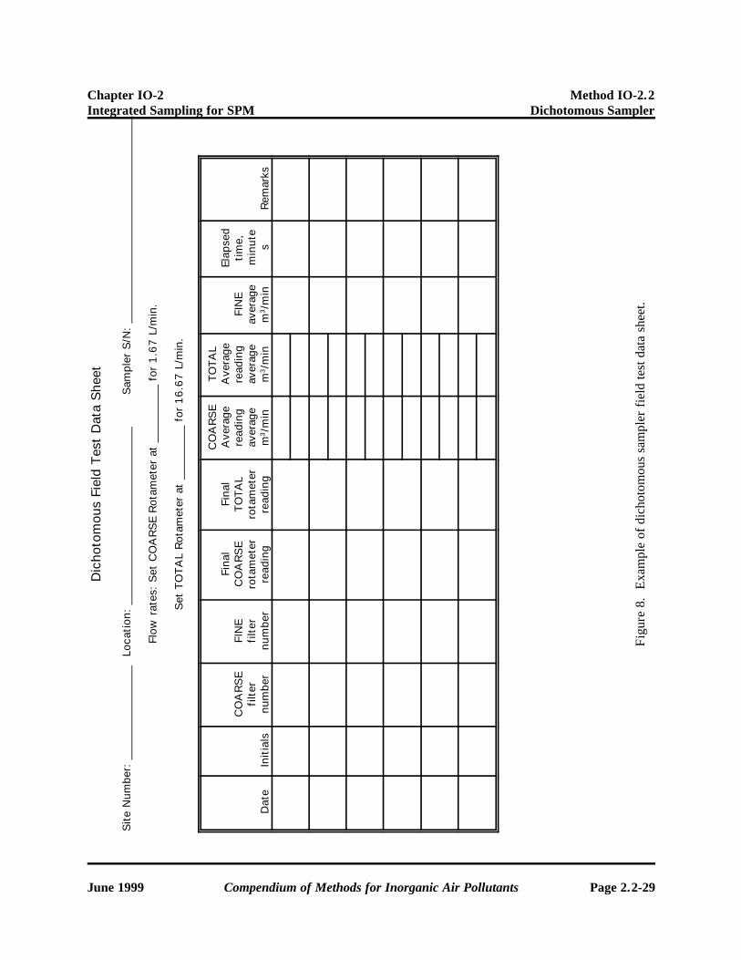
9.2.10 Set the coarse flow rate by adjusting the flow control valve to a reading on the coarse rotameterthat will give an ambient flow rate of 0.00167 m3/min (1.67 L/min), as determined by a previous calibrationof the sampler. Record the rotameter set point on the Dichotomous Field Test Data Sheet (see Figure 8).The vacuum gauge will read approximately zero. The flow control valve will require only minor adjustmentbetween samples. A Coarse Rotameter Calibration Table should be developed for each sample based uponmost recent calibration curves.
9.2.11 Turn the mechanical timer switch to "off." Set the correct time by rotating the dial until thecorrect day and time of day appear at the red pointer. Position the "on" tripper to the day and time of daythat the unit is to begin sampling. Position the "off" tripper to the day and time of day that the unit is to stopsampling. Reset the elapsed time indicator to 0000.00 min by pressing the reset button. Close the front coverof the control module. The unit is ready to sample.
9.2.12 After the sampling period is over, turn the sampler on and allow it to run approximately 5 min.Record the final total and coarse rotameter readings on the Dichtomous Field Test Data Sheet. Turn thesampler off.
9.2.13 Remove the exposed filter cassette from the coarse flow filter holder and return it to the plasticcontainer from which it originally came. Record the filter number on the Dichotomous Field Test DataSheet.
9.2.14 Remove the exposed filter cassette from the fine flow filter holder and return it to the plasticcontainer from which it originally came. Record the filter number on the Dichotomous Field Test DataSheet.
9.2.15 Ship both filters, along with a chain-of-custody, back to the laboratory for gravimetric andelemental analysis.
9.3 Filter Media
9.3.1 A number of different media are available in the standard 37-mm size. They are:
• Pallflex TX40 Filters.• Teflon® Filters.• Quartz Fiber Filters.
These media are currently acceptable for use in EPA equivalent and reference PM10 instrumentation. All aresuitable for particulate mass measurement; however, one type of media may be preferable to othersdepending upon the type of post-collection chemical speciation desired. Filter media may be used for EPAPM10 reporting purposes as long as the material meets the collection efficiency, integrity, and alkalinityrequirements of 40 CFR Part 50 Appendix J. Further, materials must have relatively low pressure dropcharacteristics so that the sampler can maintain the 16.7 L/min flow rate required for the PM10 inlet duringan entire 24-h sampling period.
9.3.2 Take deliberate care when handling and transporting sample filters. Quartz fiber filters are verybrittle, while other types of material are susceptible to tearing.
[Note: Keep filters clean and never touch filters with fingers. Filters should be stored and transported inpetri dishes. Only non-serrated forceps should be used to handle the 37-mm filters used with the sampler.]
Inspect each filter visually for integrity before use. Check for pinholes, chaff or flashing, loose material,discoloration, and non-uniformity.

Chapter IO-2 Method IO-2.2Integrated Sampling for SPM Dichotomous Sampler
June 1999 Compendium of Methods for Inorganic Air Pollutants Page 2.2-11
9.3.3 Pre-weighing of Filters9.3.3.1 Filters ready for field use have been pre-weighed in the laboratory, under prescribed climate
control conditions of temperature and relative humidity, using Inorganic Compendium Method IO-3.1,Selection, Extraction and Preparation of Filter Material.
9.3.3.2 Within Method IO-3.1, the user is provided guidance on proper selection of filter material inorder to meet project specific data quality objectives (DQOs), how to visually inspect a new lot of filters forconsistency and identification of defects, and initial weighing of the filters so a net concentration of particulatematter can be calculated after sampling.
9.3.3.3 The user should follow the procedures outlined within Method IO-3.1 as part of meeting theprogram’s standard operating procedures (SOPs) and quality control (QC) requirements.
Chapter IO-2 Method IO-2.2Integrated Sampling for SPM Dichotomous Sampler
Page 2.2-12 Compendium of Methods for Inorganic Air Pollutants June 1999
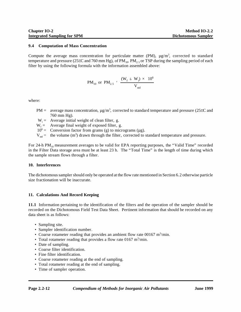
PM10 or PM2.5 '(Wf & W i) × 106
Vstd
9.4 Computation of Mass Concentration
Compute the average mass concentration for particulate matter (PM), µg/m3, corrected to standardtemperature and pressure (25EC and 760 mm Hg), of PM10, PM2.5 or TSP during the sampling period of eachfilter by using the following formula with the information assembled above:
where:
PM = average mass concentration, µg/m3, corrected to standard temperature and pressure (25EC and760 mm Hg).
Wi = Average initial weight of clean filter, g.Wf = Average final weight of exposed filter, g.106 = Conversion factor from grams (g) to micrograms (µg).Vstd = the volume (m3) drawn through the filter, corrected to standard temperature and pressure.
For 24-h PM10 measurement averages to be valid for EPA reporting purposes, the “Valid Time” recordedin the Filter Data storage area must be at least 23 h. The “Total Time” is the length of time during whichthe sample stream flows through a filter.
10. Interferences
The dichotomous sampler should only be operated at the flow rate mentioned in Section 6.2 otherwise particlesize fractionation will be inaccurate.
11. Calculations And Record Keeping
11.1 Information pertaining to the identification of the filters and the operation of the sampler should berecorded on the Dichotomous Field Test Data Sheet. Pertinent information that should be recorded on anydata sheet is as follows:
• Sampling site. • Sampler identification number. • Coarse rotameter reading that provides an ambient flow rate 00167 m3/min. • Total rotameter reading that provides a flow rate 0167 m3/min. • Date of sampling. • Coarse filter identification. • Fine filter identification. • Coarse rotameter reading at the end of sampling. • Total rotameter reading at the end of sampling. • Time of sampler operation.

Chapter IO-2 Method IO-2.2Integrated Sampling for SPM Dichotomous Sampler
June 1999 Compendium of Methods for Inorganic Air Pollutants Page 2.2-13
• Comments about sampler and sample period.
11.2 Information should be recorded in a diary format in an instrument logbook. This log should indicatethe time and nature of maintenance, periods when samplers are out of service and the reason, dates of fieldcalibration flow checks and QC checks, and unusual occurrences such as power outages, dates of samplerreplacements, and operating personnel changes. This log will be used to help identify unusual trends orpatterns that may be site-, operator-, or sampler-induced.
11.3 The following data are obtained by calculations of the collected values acquired in Section 9.
11.3.1 Average Coarse Rotameter Reading. This reading is determined by adding the beginning coarserotameter reading to the final coarse rotameter reading and dividing by 2. Look up the coarse rotameterreading on the Coarse Rotameter Calibration Table for the corresponding standard flow rate (in m3/min).
11.3.2 Average Total Rotameter Reading. This reading is determined by adding the beginning totalrotameter reading to the final total rotameter reading and dividing by 2. Look up the average total rotameterreading on the Total Rotameter Calibration Table for the corresponding standard flow rate (in m3/min).
11.3.3 Fine Average Flow. Subtract the coarse flow rate from the average total flow rate.11.3.4 Percent Error. Subtract the orifice flow rate (m3/min) from the total sampler flow rate (m3/min)
and divide by the orifice flow rate (m3/min).11.3.5 QC Flowcheck. Multiply by 100 to obtain the QC flowcheck percent.
12. Performance Criteria and QA
12.1 Flow Rates
12.1.1 Decreases in flow rate during sampling of >10% from the initial setpoint will require that theunit be checked for performance.
12.1.2 Changes in flow rate calibration of >10%, as determined by a field calibration check, will requirethat the unit be checked for performance and recalibrated.
12.2 Filter Quality
Any filter that is obviously damaged (i.e., torn or frayed) should be voided.
13. Field Flow Calibration Check of Dichotomous Samplers
13.1 Scope
During routine operation of a dichotomous sampler, a flow calibration check should be performedperiodically to assure sample accuracy and equipment performance. The check is made by installing anorifice device (calibrated over the operating range of the total rotameter) on the inlet to the sampler, asillustrated in Figure 5, without the mass flow controller.
Chapter IO-2 Method IO-2.2Integrated Sampling for SPM Dichotomous Sampler
Page 2.2-14 Compendium of Methods for Inorganic Air Pollutants June 1999
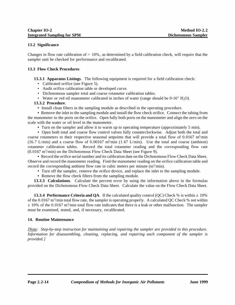
13.2 Significance
Changes in flow rate calibration of >10%, as determined by a field calibration check, will require that thesampler unit be checked for performance and recalibrated.
13.3 Flow Check Procedures
13.3.1 Apparatus Listings. The following equipment is required for a field calibration check:• Calibrated orifice (see Figure 5).• Audit orifice calibration table or developed curve.• Dichotomous sampler total and coarse rotameter calibration tables.• Water or red oil manometer calibrated in inches of water (range should be 0-16" H2O).
13.3.2 Procedure.• Install clean filters in the sampling module as described in the operating procedure.• Remove the inlet to the sampling module and install the flow check orifice. Connect the tubing from
the manometer to the ports on the orifice. Open fully both ports on the manometer and align the zero on thescale with the water or oil level in the manometer.
• Turn on the sampler and allow it to warm up to operating temperature (approximately 5 min).• Open both total and coarse flow control valves fully counterclockwise. Adjust both the total and
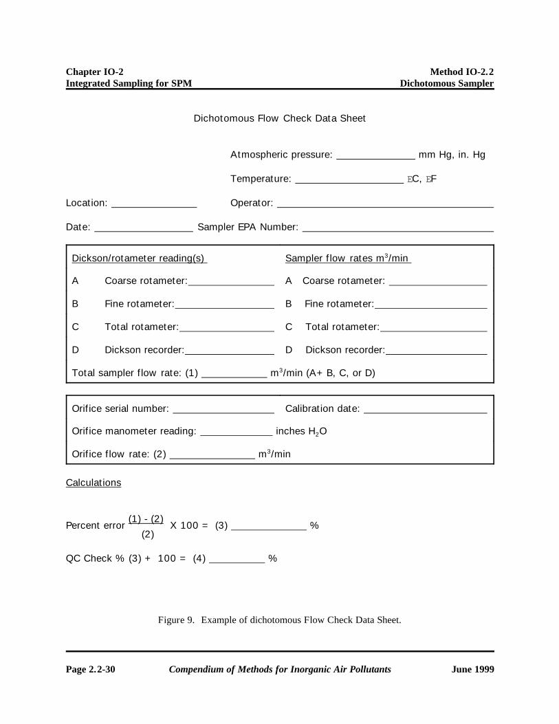
coarse rotameters to their respective seasonal setpoints that will provide a total flow of 0.0167 m3/min(16.7 L/min) and a coarse flow of 0.00167 m3/min (1.67 L/min). Use the total and coarse (ambient)rotameter calibration tables. Record the total rotameter reading and the corresponding flow rate(0.0167 m3/min) on the Dichotomous Flow Check Data Sheet (see Figure 9).
• Record the orifice serial number and its calibration date on the Dichotomous Flow Check Data Sheet.Observe and record the manometer reading. Find the manometer reading on the orifice calibration table andrecord the corresponding ambient flow rate in cubic meters per minute (m3/min).
• Turn off the sampler, remove the orifice device, and replace the inlet to the sampling module.• Remove the flow check filters from the sampling module.
13.3.3 Calculations. Calculate the percent error by using the information above in the formulasprovided on the Dichotomous Flow Check Data Sheet. Calculate the value on the Flow Check Data Sheet.
13.3.4 Performance Criteria and QA. If the calculated quality control (QC) Check % is within ±10%of the 0.0167 m3/min total flow rate, the sampler is operating properly. A calculated QC Check % not within±10% of the 0.0167 m3/min total flow rate indicates that there is a leak or other malfunction. The samplermust be examined, tested, and, if necessary, recalibrated.
14. Routine Maintenance
[Note: Step-by-step instruction for maintaining and repairing the sampler are provided in this procedure.Information for disassembling, cleaning, replacing, and repairing each component of the sampler isprovided.]

Chapter IO-2 Method IO-2.2Integrated Sampling for SPM Dichotomous Sampler
June 1999 Compendium of Methods for Inorganic Air Pollutants Page 2.2-15
14.1 Sampling Module
14.1.1 All parts are sealed with O-rings. Internal particulate deposits accumulate primarily on the outerand inner surfaces of the tip of the receiver tube in the virtual impactor head. The receiver tube should beinspected periodically for such particulate deposits and cleaned as required. The receiver tube should becleaned every 3-4 months. The remaining inner surfaces should be cleaned every 6-12 months. Cleaningshould be done with alcohol or water using a camel's-hair brush. Disassembly and internal cleaning shouldnormally not be attempted in the field.
14.1.2 The diametral O-rings in the aerosol inlet and the flow-splitting chamber should be conditionedperiodically with vacuum grease (see Figure 2).
14.1.3 The bug screen in the aerosol inlet should be cleaned periodically during the summer months.A diametral O-ring in the aerosol inlet acts as the seal.
14.1.4 Sampler connector tubing should be examined periodically and replaced as necessary (seeFigure 3).
14.1.5 Recalibration is required if the unit is disassembled for cleaning or if a field flow check revealsthat the unit is out of limits. Clean the sampling module as follows:
14.1.6 Dismantle and clean the 10-µm inlet assembly by removing four Phillips head screws and wipingout the interior with the cleaner and paper towels. Allow the unit to dry, then carefully reassemble.
14.1.7 Dismantle and clean the main sample head by following these steps: • Mark each assembly point of the sample inlet with pen or pencil to provide "match marks" during
reassembly. • Disassemble the unit, taking care to retain all O-rings and miscellaneous parts.
[Note: Many of the assembly screws may appear frozen, in which case pliers or penetrating oil may berequired.]
• Clean all interior surfaces with the general-purpose cleaner, paying particular attention to smallopenings and crevices. Cotton swabs or a small brush are helpful in these areas. Completely dryall components.
• Reassemble the unit in accordance with the previously scribed match marks. Take particular careto ensure that all O-ring seals are properly seated and that all screws are uniformly tight.
14.2 Control Module
[Warning: Unplug the line power cord from its receptacle before removing the front panel of the AndersenModel 244 control module enclosure.]
14.2.1 Filter Elements. After approximately 12-24 months of sampling, the vacuum pump jar filters forthe coarse and fine particle flows may need replacement. In normal operation, air entering these jars isfiltered by the two 17-mm membrane filters in the sampling module. Hence, jar filter replacement isinfrequent. To replace these filters, unplug the line power cord and remove the front panel of the controlmodule by removing the 6 screws. The filter jar from the coarse-particle flow is the small jar (approximately2.5" dia. x 3" long) in the upper left side of the enclosure. Unscrew the jar, remove the old filter element,and replace with a new element. Tighten the jar very tightly when installing, to avoid leaks. Thefine-particle filter jar is behind the coarse-particle filter jar. It is approximately 3" dia. x 5" long and is theone closest to the bulkhead fitting on the side of the enclosure.

Chapter IO-2 Method IO-2.2Integrated Sampling for SPM Dichotomous Sampler
Page 2.2-16 Compendium of Methods for Inorganic Air Pollutants June 1999
14.2.2 Vacuum Pump. The diaphragm of the vacuum pump should be replaced routinely at 1-yrintervals or if sampler vacuum is suddenly reduced and a leak check indicates there are no leaks in thesystem. To replace the diaphragm, unplug the line voltage and remove the front panel (see Figure 4).Remove the finned head of the pump by removing the 6 head screws. Remove the four diaphragm platehold-down screws and change the diaphragm. To reassemble, reverse the procedure, making sure that thescrew clearance cavity in the plate is lined up under the intake valve screw heads and that all head screws aretightened evenly. Clean the control module as follows (see Figure 4):
• Ensure that power is disconnected from the unit. If compressed air is available, open the unit andblow out loose dust and dirt.
• Wipe down all surfaces with the general-purpose cleaner and towels. Make note of any obviousproblems in the unit and take action to correct them before completion of cleaning.
• Check rotameters for cleanliness. If they are dirty or contain water, they must be removed andcleaned. (If water is found, the interior of the vacuum pump may be damaged. It will have to be opened forinspection and possible repair.) Rotameters are cleaned by the following steps:
• Remove the tubing from the total rotameter output port and any other connected tubing that mayprove too inflexible to allow removal of the rotameters.
• Remove the four screws securing the rotameter assembly to the front panel.• Slip the assembly back from the front panel to gain access to the allen screws in the tops of the
rotameters. Remove the protective covers from each rotameter.• While holding the glass rotameter with one hand, loosen the large allen screws just enough to
allow removal of the unit. Repeat for each unit.• Clean the two rotameters with the cleaner, followed by a thorough rinsing in distilled water. (To
properly clean the unit, remove the float and its retainers. The retainers are easily removed withthe aid of a wire hook fashioned from a paper clip.)
• Allow the tubes to dry thoroughly. Then reassemble.• Remove and clean all filter jars (check each for possible cracks and replace if necessary). Clean or
replace all dirty filter elements.• Clean the fan's blades and housing. Observe the housing for any dirt buildup that could cause the
fan to lock up.• Clean exterior surfaces of the unit, ensuring that all cooling vents are open. Check all mounting
brackets to ensure that they are tight and in good repair.• When all cleaning operations and necessary repairs are completed, close the module and reconnect
the sample module to allow performance of leak and calibration checks.
14.3 Refurbishment Procedures
Step-by-step instruction for refurbishing samplers that may have been operated in the field for extendedperiods are described in this procedure. Information is provided for disassembling, cleaning, replacing, andrepairing each component of the sampler.
14.3.1 Control Module. • Using a general household cleaner, clean all exterior surfaces of the module (see Figure 4). Observe
the general condition of the cabinet and hardware items. Any damaged or missing components must bereplaced before the unit is returned to service.
• Open the front door of the unit and clean the interior surfaces. Examine the front panel for thepresence of water in the rotameters. (If any water is present, the vacuum pump must be inspected for interiorwater damage.)

Chapter IO-2 Method IO-2.2Integrated Sampling for SPM Dichotomous Sampler
June 1999 Compendium of Methods for Inorganic Air Pollutants Page 2.2-17
• Using a combination of cleaner and compressed air, clean all interior surfaces of the unit. Remove,clean, and replace all filter jars and media. Replace any damaged components.
• Remove and clean both rotameters by removing the 4 bracket screws, disconnecting necessarytubing, and pulling the assembly free. Remove each glass tube by loosening the allen screw at the end of eachrotameter. Remove the white stops and ball floats from the glass rotameters. Flush out the rotameters withdistilled water; then swab them out with a soft tissue and set aside to dry thoroughly before reinstallation.Caution: Be sure to check the cooling fan. It tends to collect dust, and if the buildup is sufficient, the bladeswill bind and subsequently destroy the fan. Screens are available to filter out this dust and should be installedif possible during the refurbishment process.
• Check all electrical wiring and connections. Replace any frayed or damaged components.Caution: If water was initially observed in the rotameters, check the vacuum pump for water damage byremoving the cylinder head and valve plate and removing any moisture or corrosion.
• Reassemble rotameters (only if they are completely dry) and reinstall them in the unit. Make a finalcheck of all plumbing to ensure that reconnections have been made properly and that all fittings are tight.
• Temporarily secure the front panel of the module and perform a brief operational check as follows:• Connect power to the unit and manually turn on sampler.• Advance flow control valves and observe rotameters for smooth operation throughout their range.
Caution: If the sampler is equipped with a filter overload switch, it must be turned off or disabled (byremoving one of the relay coil wires) before a leak or performance test can be done.
• Leak-test the unit by capping off the tubing inlet ports and observing the vacuum gauges for amaximum reading.
• Once a maximum has occurred, turn off the sampler and observe the rate of decrease in vacuumreadings. A slow, gradual decrease requiring 60 s or more to reach a minimum is the mark of agood system. A rapid decline indicates a leakage problem that should be investigated.
[Note: Filter jars are often leakage areas, and some pumps tend to leak. A leaky pump can be identified byplugging the output port immediately after turning off power to the unit. If the rate of decline is slowed, thenthe system is acceptable.]
14.3.2 Sample Module. This assembly initially should be inspected for any damaged or missingcomponents. Attention should be given to all hardware items at this point; penetrating oil may need to beapplied to selected hardware to disassemble the units for cleaning. Actual disassembly and cleaning shouldproceed as follows:
• Disassemble the unit as shown into various subassemblies.• Using general-purpose household cleaner, clean all interior surfaces, paying special attention to the
various small nozzles and openings in the various components. Rinse with distilled water and dry thoroughly.• Inspect all seals in the unit and replace any questionable ones. Pay special attention to those that seal
the filer cassettes.• Reassemble the module, using stainless steel hardware to replace all defective screws.• Disassemble and clean the 10-µm inlet. To disassemble the inlet, unscrew the 3" diameter outer-tube
containing the impaction chamber. Clean all interior surfaces. Inspect and replace the O-ring seal, ifnecessary, and reassemble the unit. The precipitation trap should be removed and cleaned at the same time.
14.3.3 Operational Tests. The following procedure provides tests to determine if the sampler is readyfor field operation. The sampling system should be set up in its normal operating configuration with acalibrated flow measuring device connected in place of the inlet hat (see Figure 5). Clean filters should beinserted in the sample module, and all front panels toggle switches on the control module should be switched
Chapter IO-2 Method IO-2.2Integrated Sampling for SPM Dichotomous Sampler
Page 2.2-18 Compendium of Methods for Inorganic Air Pollutants June 1999
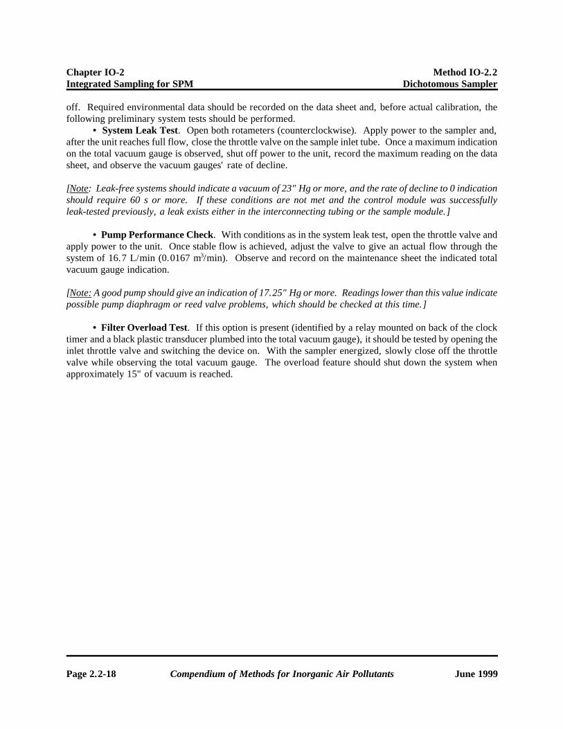
off. Required environmental data should be recorded on the data sheet and, before actual calibration, thefollowing preliminary system tests should be performed.
• System Leak Test. Open both rotameters (counterclockwise). Apply power to the sampler and,after the unit reaches full flow, close the throttle valve on the sample inlet tube. Once a maximum indicationon the total vacuum gauge is observed, shut off power to the unit, record the maximum reading on the datasheet, and observe the vacuum gauges' rate of decline.
[Note: Leak-free systems should indicate a vacuum of 23" Hg or more, and the rate of decline to 0 indicationshould require 60 s or more. If these conditions are not met and the control module was successfullyleak-tested previously, a leak exists either in the interconnecting tubing or the sample module.]
• Pump Performance Check. With conditions as in the system leak test, open the throttle valve andapply power to the unit. Once stable flow is achieved, adjust the valve to give an actual flow through thesystem of 16.7 L/min (0.0167 m3/min). Observe and record on the maintenance sheet the indicated totalvacuum gauge indication.
[Note: A good pump should give an indication of 17.25" Hg or more. Readings lower than this value indicatepossible pump diaphragm or reed valve problems, which should be checked at this time.]
• Filter Overload Test. If this option is present (identified by a relay mounted on back of the clocktimer and a black plastic transducer plumbed into the total vacuum gauge), it should be tested by opening theinlet throttle valve and switching the device on. With the sampler energized, slowly close off the throttlevalve while observing the total vacuum gauge. The overload feature should shut down the system whenapproximately 15" of vacuum is reached.
Chapter IO-2 Method IO-2.2Integrated Sampling for SPM Dichotomous Sampler
June 1999 Compendium of Methods for Inorganic Air Pollutants Page 2.2-19
15. References
1. Dzubay, T.G., Development and Evaluation of Composite Receptor Methods, EPA Project Summary,EPA-600/3-88-026, U. S. Environmental Protection Agency, Research Triangle Park, NC, 27711, September1988.
2. Inhalable Particulate Network Operations and Quality Assurance Manual, Office of Research andDevelopment, Environmental Monitoring Systems Lab, U. S. Environmental Protection Agency, ResearchTriangle Park, NC, 27711, May 1980.
3. Bevington, P.R, Data Reduction and Error Analysis for the Physical Sciences, McGraw-Hill Book Co.,New York, NY.
4. Dzubay, T.G., "Chemical Element Balance Method Applied to Dichotomous Sampler Data," Annals ofthe New York Academy of Sciences, 1980.
5. Goulding, F.S., and Jaklevic, J.M., Fabrication of Monitoring System for Determining Mass andComposition of Aerosol as a Function of Time, U. S. Environmental Protection Agency, Research TrianglePark, NC, 27711, EPA 650/2-75-041, June 1975.
6. Hodges, M.G., and Wright, E.W., Intercomparison of High-Volume, PM10, and Dichotomous ParticulateMatter Samplers at a Site with Low Particulate Matter Concentrations, Environmental Science andEngineering, Inc., Gainesville, FL, September 1987.
7. NIST Standard Reference Materials Catalog, National Institute of Standards and Technology, Publ. 260,U.S. Department of Commerce, Washington, DC, p. 64, June 1986.
8. Operating Procedure for the Sierra Series 244E Dichotomous Sampler Equipped with the Andersen Model246B PM10 Inlet, Environmental Monitoring Systems Lab, Office of Research and Development, U. S.Environmental Protection Agency, Research Triangle Park, NC, 27711, May 1980.
9. Stevens, R.K., and Dzubay, T.G., "Dichotomous Sampler - A Practical Approach to AerosolFractionation and Collection," EPA 600/2-78-112, Environmental Monitoring Systems Lab, Office ofResearch and Development, U. S. Environmental Protection Agency, Research Triangle Park, NC 27711,June 1978.

Chapter IO-2 Method IO-2.2Integrated Sampling for SPM Dichotomous Sampler
Page 2.2-20 Compendium of Methods for Inorganic Air Pollutants June 1999
TABLE 1. SPECIFICATIONS FOR THE ANDERSEN MODEL 244DICHOTOMOUS SAMPLER
Item Specifications
Collection efficiency Mass median diameter at 50% collection efficiency forequivalent spherical particles at 1 g/cm3 is 2.5 µm
Internal losses Maximum value over range of 0-20 µm is <1-2% andoccurs at 2.5 µm. Average loss for all particles is<1%.
Flow rates Total flow: 1 m3/h, or 16.7 L/min; Fine-particle flow: 0.9 m3/h,, or 15.0 L/min;Coarse-particle flow: 0.1 m3, or 1.67 L/min.
Flowmeters Precision rotameters, +1.5% accuracy at above flows.
Concentration ratio 10:1.
Vacuum pump Diaphragm type, split phase motor, 1/4 hp.
Timer Mechanical, 7-day, double pole, double throw,120 volt, 60 Hz. Accuracy: +15 min in 24 h.
Elapsed time indicator 9999.99 min; resettable.
Filter media 37-mm membrane or glass fiber; Teflon® membranemedia recommended.
Filter holder Circular, polyolefin, 1.750" o.d.
Interconnecting tubing 10 m long; 3/8" o.d. for fine-particle flow; 1/4" o.d.for coarse-particle flow.
Aerosol inlet 10 µm nominal cutpoint over approximately 0-20km/hwind speed range; includes bug screen.
Power required 115 V a.c. +15%, 50-60 Hz, 200 W.
Overall dimensions Control module: 16" H x 11" W x 22" L; samplingmodule: 40" H x 25.63" diam. tripod base bolt circle.
Net weight Control module: 50 lb; sampling module: 15 lb.
Total shipping weight 85 lb.

Chapter IO-2 Method IO-2.2Integrated Sampling for SPM Dichotomous Sampler
June 1999 Compendium of Methods for Inorganic Air Pollutants Page 2.2-21
TABLE 2. MINIMUM SAMPLER SITING CRITERIADistance from supporting
structure, meters
ScaleHeight above
ground, meters Vertical Horizontala Other spacing criteria
Micro 2 to 7 >2 >2 1. Should be >20 metersfrom trees.
Middle,neighborhood,urban, andregional scale
2 to 15 >2 >2 2. Distance from samplerto obstacle, such asbuildings, must be twicethe height and theobstacle protrudes abovethe sampler.
3. Must have unrestrictedairflow 270 degreesaround the sampler inlet.
4. No furnace orincineration flues shouldbe nearby.b
5. Spacing from roadsvaries with traffic (see40 CFR 58,Appendix E).
6. Sampler inlet is at least2 m but not greater than4 m from any collocatedPM10 sampler. (See40 CFR 58,Appendix E).
aWhen inlet is located on rooftop, this separation distance is in reference to walls, parapets, or penthouseslocated on the roof.bDistance depends on the height of furnace or incineration flues, type of fuel or waste burned, and quality offuel (sulfur, ash, or lead content). This is to avoid undue influences from minor pollutant sources.

Chapter IO-2 Method IO-2.2Integrated Sampling for SPM Dichotomous Sampler
Page 2.2-22 Compendium of Methods for Inorganic Air Pollutants June 1999
Figure 1. Andersen Model 244 dichotomous sampler.

Chapter IO-2 Method IO-2.2Integrated Sampling for SPM Dichotomous Sampler
June 1999 Compendium of Methods for Inorganic Air Pollutants Page 2.2-23
Figure 2. Inlet for the Andersen Model 244 dichotomous sampler.

Chapter IO-2 Method IO-2.2Integrated Sampling for SPM Dichotomous Sampler
Page 2.2-24 Compendium of Methods for Inorganic Air Pollutants June 1999
Figure 3. The virtual impactor principle of operation.

Chapter IO-2 Method IO-2.2Integrated Sampling for SPM Dichotomous Sampler
June 1999 Compendium of Methods for Inorganic Air Pollutants Page 2.2-25
Fig
ure
4. C
ontr
ol m
odul
e of
the
And
erse
n di
chot
omou
s sa
mpl
er.

Chapter IO-2 Method IO-2.2Integrated Sampling for SPM Dichotomous Sampler
Page 2.2-26 Compendium of Methods for Inorganic Air Pollutants June 1999
Fig
ure
5. S
chem
atic
of
the
And
erse
n ca
libra
tion
setu
p us
ing
a m
ass
flow
met
er a
s th
e tr
ansf
er s
tand
ard.

Chapter IO-2 Method IO-2.2Integrated Sampling for SPM Dichotomous Sampler
June 1999 Compendium of Methods for Inorganic Air Pollutants Page 2.2-27
Fig
ure
6. E
xam
ple
of d
icho
tom
ous
flow
ori
fice
cal
ibra
tion
curv
e.
Chapter IO-2 Method IO-2.2Integrated Sampling for SPM Dichotomous Sampler
Page 2.2-28 Compendium of Methods for Inorganic Air Pollutants June 1999
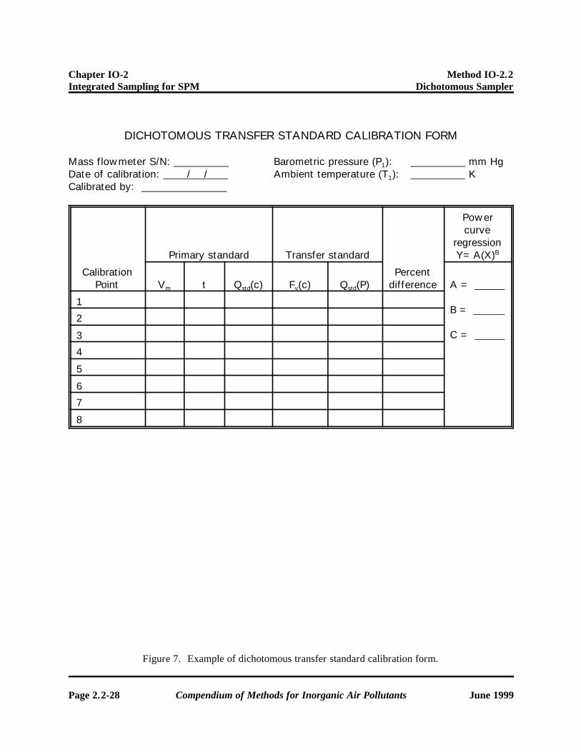
DICHOTOMOUS TRANSFER STANDARD CALIBRATION FORM
Mass flowmeter S/N: Barometric pressure (P1): mm HgDate of calibration: / / Ambient temperature (T1): KCalibrated by:
CalibrationPoint
Primary standard Transfer standard
Percentdifference
Powercurve
regressionY=A(X)B
Vm t Qstd(c) Fv(c) Qstd(P) A =
B =
C =
1
2
3
4
5
6
7
8
Figure 7. Example of dichotomous transfer standard calibration form.
Chapter IO-2 Method IO-2.2Integrated Sampling for SPM Dichotomous Sampler
June 1999 Compendium of Methods for Inorganic Air Pollutants Page 2.2-29
Dic
hoto
mou
s Fi
eld
Tes
t D
ata
She
et
Site
Num
ber:
Loca
tion
:
Sam
pler
S/N
:
Flow
rat
es:
Set
CO
ARSE
Rot
amet
er a
t
f
or 1
.67 L
/min
.
Set
TO
TA
L Rot
amet
er a
t
fo
r 16.6
7 L
/min
.
Dat
eIn
itia
ls
CO
ARSE
filter
num
ber
FIN
Efilter
num
ber
Fina
lC
OA
RSE
rota
met
erre
adin
g
Fina
lTO
TAL
rota
met
erre
adin
g
CO
ARSE
Ave
rage
read
ing
aver
age
m3/m
in
TOTA
LA
vera
gere
adin
gav
erag
em
3/m
in
FIN
Eav
erag
em
3/m
in
Elap
sed
tim
e,m
inut
es
Rem
arks
Fig
ure
8. E
xam
ple
of d
icho
tom
ous
sam
pler
fie
ld te
st d
ata
shee
t.
Chapter IO-2 Method IO-2.2Integrated Sampling for SPM Dichotomous Sampler
Page 2.2-30 Compendium of Methods for Inorganic Air Pollutants June 1999
Dichotomous Flow Check Data Sheet
Atmospheric pressure: mm Hg, in. Hg
Temperature: EC, EF
Location: Operator:
Date: Sampler EPA Number:
Dickson/rotameter reading(s) Sampler flow rates m3/min
A Coarse rotameter: A Coarse rotameter:
B Fine rotameter: B Fine rotameter:
C Total rotameter: C Total rotameter:
D Dickson recorder: D Dickson recorder:
Total sampler flow rate: (1) m3/min (A+B, C, or D)
Orifice serial number: Calibration date:
Orifice manometer reading: inches H2O
Orifice flow rate: (2) m3/min
Calculations
Percent error (1) - (2)
X 100 = (3) % (2)
QC Check % (3) + 100 = (4) %
Figure 9. Example of dichotomous Flow Check Data Sheet.

Chapter IO-2 Method IO-2.2Integrated Sampling for SPM Dichotomous Sampler
June 1999 Compendium of Methods for Inorganic Air Pollutants Page 2.2-31
[This page intentionall left blank.]