
Sami Smith Study of Marine Communications Systems and ...
70
Helsinki Metropolia University of Applied Sciences Degree Programme in Information Technology Sami Smith Study of Marine Communications Systems and Selection Procedures for Implementing Solutions Bachelor’s Thesis. 28 November 2008 Instructor: Ville Leino, Technical Manager - Marine Operations Supervisor: Pertti Jäppinen, Senior Lecturer
Transcript of Sami Smith Study of Marine Communications Systems and ...

Helsinki Metropolia University of Applied Sciences
Degree Programme in Information Technology
Sami Smith
Study of Marine Communications Systems and
Selection Procedures for Implementing Solutions
Bachelor’s Thesis. 28 November 2008
Instructor: Ville Leino, Technical Manager - Marine Operations
Supervisor: Pertti Jäppinen, Senior Lecturer

2
Helsinki Metropolia University of Applied Sciences ABSTRACT
Author
Title
Number of Pages
Date
Sami Smith
Study of marine communications systems and selection
procedures for implementing solutions
70
28 November 2008
Degree Programme
Information Technology
Degree
Bachelor of Engineering
Instructor
Supervisor
Ville Leino, Technical Manager - Marine Operations
Pertti Jäppinen, Senior Lecturer
The project was appointed by Eniram Ltd, an IT company which offers the maritime
industry solutions in the form of turnkey packages installed aboard ships to aid crews
in enhancing many aspects of vessel performance. The need for a study and
comparison was identified into different ship-to-shore communications methods for
transmitting the data acquired from Eniram’s onboard system modules to Eniram’s
office for processing. The objective was to provide a clear procedure for selecting the
most appropriate solution for implementation aboard a ship, on a per-customer basis.
Through research into marine communications, the communications industry as a
whole, and interviews with Eniram, the project described the relevant characteristics
of the possible communications methods and their feasibilities in being employed for
Eniram’s purposes. These were according to each vessel’s operational factors, as well
as implementation and financial considerations discussed from a general project
planning viewpoint.
The project resulted in the production of a set of procedural guidelines, or a solution
map, that stipulate in a systematic manner the information that needs to be collated for
each ship installation, the factors that need to be formulated from this information,
and the consequent logical decisions required to be made when selecting the optimal
solution for a vessel.
Keywords marine communications, mobile communications, mobile satellite
services, ship-to-shore communications
3
Contents
Abbreviations............................................................................................................ 5
1 Introduction........................................................................................................... 7
2 Theoretical Background ..................................................................................... 9
2.1 Satellite Services ................................................................................................ 9
2.1.1 Satellite Orbits........................................................................................... 10
2.1.2 Satellite Coverage Areas............................................................................ 14
2.1.3 Global Maritime Distress Safety System (GMDSS)................................... 15
2.2 Inmarsat ........................................................................................................... 16
2.2.1 FleetBroadband ......................................................................................... 16
2.2.2 Fleet 77, 55 and 33 .................................................................................... 18
2.2.3 Other Inmarsat Systems............................................................................. 20
2.3 SeaMobile Enterprises...................................................................................... 22
2.4 Public Land Mobile Network (PLMN) ............................................................. 23
2.4.1 Global System for Mobile Communications (GSM)................................... 23
2.4.2 General Packet Radio Service (GPRS)....................................................... 24
2.4.3 Enhanced Data Rates for GSM Evolution (EDGE) .................................... 25
2.4.4 3G Technology.......................................................................................... 27
2.4.5 4G Technology.......................................................................................... 30
2.5 Other Ship-to-Shore Communications .............................................................. 31
3 Eniram Products................................................................................................. 33
4 Communication Modes .................................................................................... 37
4.1 Remote Reporting (RR).................................................................................... 37
4.2 Remote Diagnostics (RD)................................................................................. 37
4.3 Remote Diagnostics and Maintenance (RDM).................................................. 38
4.4 Future Requirements ........................................................................................ 38
5 Project Plan ......................................................................................................... 40
5.1 Business Requirements..................................................................................... 41
5.2 Technical Specifications................................................................................... 43
5.3 Financial Considerations .................................................................................. 46

4
5.4 Solution Map.................................................................................................... 47
5.5 Procurement ..................................................................................................... 49
5.6 Operation ......................................................................................................... 50
6 Solution Map ...................................................................................................... 53
7 Conclusion .......................................................................................................... 55
References ............................................................................................................... 56
Appendix 1: Information Map ............................................................................. 62
Appendix 2: Solution Map ................................................................................... 67

5
Abbreviations
ADU Above Deck Unit
BDU Below Deck Unit
CFM Comfort Factor Monitor
CS Coding Scheme
CSM Cargo Securing Monitor
DSM Dynamic Stability Monitor
DTA Dynamic Trimming Assistant
E-SMS Extended Safety Management System
EDGE Enhanced Data Rates for GSM Evolution
FMS Fleet Management System
FSS Fixed Satellite Service
GEO Geostationary Earth Orbit
GMDSS Global Maritime Distress Safety System
GRT Gross Registered Tonnes
GSM Global System for Mobile Communications
HRM Hull Roughness Monitor
ISDN Integrated Services Digital Network
ISL Inter Satellite Link
LA Link Adaptation
LEO Low Earth Orbit
LES Land Earth Station
MCS Modulation and Coding Scheme
MEO Medium Earth Orbit
MES Mobile Earth Station
MS Mobile Station
MSS Mobile Satellite Service
NCC Network Control Centre
NOC Network Operations Centre
RD Remote Diagnostics
RDM Remote Diagnostics and Maintenance

6
RFI Request for Information
RFQ Request for Quote
RR Remote Reporting
TCO Total Cost of Ownership
VET Vessel Emission Tracker
VMP Vessel Management Platform
VPN Virtual Private Network
WLAN Wireless Local Area Network
7
1 Introduction
This project was assigned by Edec Oy, a technical design and consultancy service
working predominantly in the marine industry, as a technological comparison for its
spin-off company, Eniram Ltd. Eniram was founded in 2005 when a necessity for
integrating maritime operational procedures and information from onboard vessel
systems was identified. With a rich heritage in the Finnish shipbuilding industry,
Eniram consists of marine system experts, captains, naval architects, software architects
and programmers. Their objective is to offer the marine industry a technologically
advanced portfolio of tools that aid crews in improving vessel performance. [1]
Eniram’s software-based vessel management systems function through the analysis of
high-precision measurements of a vessel’s operational parameters and data acquired
from integrating with the vessel’s automation systems. This enables the provision of
extremely accurate informational support for the ship’s officers, designed to aid officers
in their decision-making processes in many areas of a vessel’s operation.
Eniram’s requirement is a study and comparison of different methods for defining
remote ship-to-shore and shore-to-ship data connections for the purposes of
communicating between the Eniram office and its onboard vessel systems. With a clear
view of these methods, and the provision of a guideline (or solution map), the most
appropriate solution can be selected and implemented.
The target is the eventual implementation of communications solutions that offer the
most efficient and cost-effective methods of remotely connecting to all ships fitted with
Eniram’s products. This will enable Eniram to assess its products’ performances, detect
any problems, highlight any possible improvements and enable software updates when
necessary. Primarily, fleet-wide data acquisition in order to facilitate the optimisation of
shipping companies’ fleet operations will be possible. To do this from shore, rather than
dispatching an engineer to the vessel wherever it may be in the world, would save time
and expense.

8
Preferably, the primary method for this data connection would be to employ an existing
communications system aboard each vessel. It may transpire that such a system does not
exist or its use is not permitted, in which case the feasibility of acquiring and installing a
new communications system dedicated to the above purposes must also be evaluated.
Ultimately, when Eniram has analysed and perfected the operation of the remote
communication link, the entire system will be commissioned and handed over to the
relevant shipping company. This will empower them to monitor their vessels’
performances from their own headquarters.

9
2 Theoretical Background
2.1 Satellite Services
The type of satellite service that relates to marine communications is termed a Mobile
Satellite Service (MSS). It enables global voice and data communications through
satellite systems and Mobile Earth Stations (MESs) aboard ships, as well as on land and
in aeroplanes. The alternative to an MSS is a Fixed Satellite System (FSS) which
employs fixed terminals in satellite communications and is therefore restricted to purely
terrestrial applications, such as domestic satellite television.
Satellite systems hold many advantages, especially in marine communications. They
provide the freedom of mobile communication, independent of location and terrestrial
infrastructures, with the widest geographical areas of coverage. Wide bandwidths are
also provided through the microwave bands used by satellite systems compared to lower
frequency bands used in radio and TV applications. For example, the microwave C and
Ku frequency bands have an available spectrum of 1 GHz each which can be further
increased, or reused, through various techniques. When demand dictates, Earth Stations
can be rapidly deployed to utilise a satellite connection, compared to a terrestrial
communications network requiring ground construction works for cable-routing to an
added facility. Additionally, a total satellite service is possible from a single provider,
whereas terrestrial networks are often divided in their operation by regional and national
companies. [2]
A satellite communications system consists of three major components: the space
segment, the ground segment and the terminals. The space segment contains the
satellites which are commissioned and run by satellite operators, the major operators
including Inmarsat, Intelsat and Eutelsat. A communications satellite is a microwave
repeater station that permits users to deliver or exchange information in various forms.
Each satellite covers an area of the Earth’s surface which increases with increasing orbit
height and the wider the beam used. For a particular satellite service, the choice of
orbits and the positioning of the satellites within the orbits must guarantee continuous

10
coverage of the service area, i.e. for a global service, the full surface of the Earth must
be covered.
The ground segment consists of a network of Land Earth Stations (LESs) which are
operated by telecommunications companies and comprise fixed, land-based Earth
stations providing the link between the satellite network and the international
telecommunications network. For each satellite system or region there operates a
Network Control Centre (NCC) which monitors and controls all satellite
communications. The Network Operations Centre (NOC) communicates with all NCCs
and transfers operational information throughout the system.
In contrast to a LES which is part of the ground segment, a Mobile Earth Station (MES)
is a terminal device installed on a ship to enable the user to communicate with land-
based or marine subscribers via satellite. The MES equipment comprises the Above
Deck Unit (ADU), containing the antenna unit which includes a radome and a stabilised
antenna dish with tracking electronics and RF equipment; and the Below Deck Unit
(BDU), containing the main communications unit and power supply unit.
2.1.1 Satellite Orbits
There exist three main types of orbits in which communications satellites operate
around the Earth, named Low Earth Orbit (LEO), Medium Earth Orbit (MEO) and
Geostationary Earth Orbit (GEO), characterised by their altitudes above the Earth’s
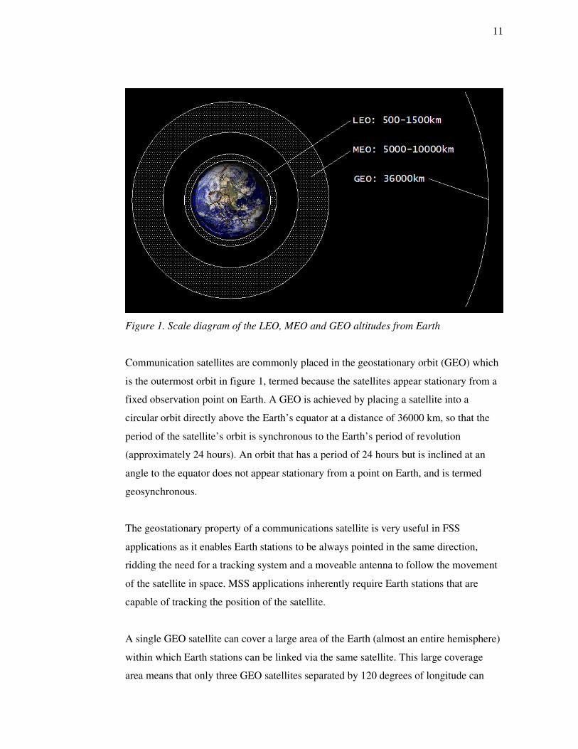
surface, as illustrated in figure 1 below.
11
Figure 1. Scale diagram of the LEO, MEO and GEO altitudes from Earth
Communication satellites are commonly placed in the geostationary orbit (GEO) which
is the outermost orbit in figure 1, termed because the satellites appear stationary from a
fixed observation point on Earth. A GEO is achieved by placing a satellite into a
circular orbit directly above the Earth’s equator at a distance of 36000 km, so that the
period of the satellite’s orbit is synchronous to the Earth’s period of revolution
(approximately 24 hours). An orbit that has a period of 24 hours but is inclined at an
angle to the equator does not appear stationary from a point on Earth, and is termed
geosynchronous.
The geostationary property of a communications satellite is very useful in FSS
applications as it enables Earth stations to be always pointed in the same direction,
ridding the need for a tracking system and a moveable antenna to follow the movement
of the satellite in space. MSS applications inherently require Earth stations that are
capable of tracking the position of the satellite.
A single GEO satellite can cover a large area of the Earth (almost an entire hemisphere)
within which Earth stations can be linked via the same satellite. This large coverage
area means that only three GEO satellites separated by 120 degrees of longitude can
12
achieve almost global coverage. It is not possible for GEO satellites to cover the polar
regions as at these higher latitudes the satellites will appear too low on the horizon. This
low elevation introduces increased attenuation of the signals due to their longer trans-
atmospheric path.
The high range between a GEO satellite and an Earth station makes the design of the
link quite stringent in terms of providing adequate received signal power. The range
also introduces a round-trip propagation delay via the satellite of approximately 0.25
seconds between a pair of Earth stations. Additionally, heavy signal processing may be
required due to weak signal levels, which can further increase the delay to one second
between two Earth stations [Leino V, Eniram Ltd, 9 September 2008, personal
communication].
Non-geosynchronous satellites are situated in orbits lower than 36000 km and hence
have periods of revolution shorter than 24 hours. This means that a non-geosynchronous
satellite always appears to move past a point on the Earth and, therefore, multiple
satellites are required in a non-geosynchronous satellite network to provide continuous
coverage of a given region of the Earth.
The lowest of satellite system orbits are termed Low Earth Orbits (LEOs) and consist of
altitudes ranging from 500 to 1500 km [2], which equates to an orbiting period of only
1.6 to 1.9 hours. LEOs are not constrained to the equatorial plane and can be inclined at
any angle and can therefore orbit in the polar plane. LEO satellites require signals to
traverse significantly shorter distances than GEO satellites, and therefore minimise the
power required and reduce round-trip propagation delays to a few milliseconds.
The short orbital periods of LEO satellites produce brief durations (typically a few
minutes) during which a single LEO satellite can serve a particular Earth station. This
introduces the necessity for LEO satellites to hand off connections, while they are still
in progress, to other satellites by way of Inter Satellite Links (ISLs). Since LEO
satellites have smaller coverage areas, they are required to handle fewer subscribers and

13
the requirements of the satellite communications equipment are more relaxed. However,
substantially more satellites are required to provide global coverage.
A compromise between LEO and GEO is the Medium Earth Orbit (MEO) with altitudes
ranging from 5000 to 10000 km [3], equating to orbital periods of 3.4 to 5.8 hours. For
higher MEO altitudes, a MEO satellite has a much longer period and thus tends to
‘hang’ over a given region on the Earth for a few hours, and global coverage can be
achieved with 10-15 satellites. Transmission distance and propagation delay are greater
than for LEO but still significantly less than for GEO.
The advantages and disadvantages of the three types of orbit employed by satellite
networks are displayed in table 1 below.
Table 1. Advantages and disadvantages of GEOs, LEOs and MEOs (Information
gathered from Lutz et al. (2000) [3])

14
As can be seen from table 1, MEOs combine the advantages of both GEOs and LEOs.
With regards to marine satellite communications, it is worth noting that any vessels
operating in the polar regions and requiring satellite connectivity, will not benefit from a
GEO satellite network.
2.1.2 Satellite Coverage Areas
A satellite’s coverage area, also known as a footprint, is the area of the Earth’s surface
for which the satellite can provide sufficient signal strength for communications
between itself and Earth stations in the area. The coverage area is dependent on the
satellite’s altitude, so it follows that LEO satellites have the smallest coverage areas and
GEO satellites the largest. When a satellite system is required to provide
communications for a service area larger than a single satellite’s coverage area, multiple
satellites will be employed to form a constellation.
The beam from a satellite antenna covers an area with the maximum signal strength in
the centre of the area, directly below the satellite, and decreasing signal strengths further
out from the centre. As well as global beams, highly focussed spot beams can be
generated which offer a much smaller coverage area but reduced the size requirement of
the receiving antenna. Therefore, the smaller the beam-size, the greater the signal
strength on Earth and the smaller the receiving antenna can be, enabling handheld MESs
to operate. Many of these spot beams can be used to fill a coverage area, creating a
cellular architecture with overlapping beams separated by different frequency bands.
For example, Iridium, a LEO satellite system, employs a constellation of 66 satellites
arranged into six polar orbits of eleven satellites each at an altitude of 780 km to provide
completely global coverage with each satellite using 48 spot beams [4]. In contrast, the
latest Inmarsat-4 GEO satellite system employs a constellation of four satellites for
global coverage (except for the polar regions) using one global beam, 19 wide spot
beams and over 200 narrow spot beams per satellite [5].

15
2.1.3 Global Maritime Distress Safety System (GMDSS)
The Global Maritime Distress Safety System (GMDSS) is an internationally ratified set
of procedures and equipment needed to implement search and rescue at sea, providing
automatic distress alerting and locating, search and rescue coordination, maritime safety
information broadcasts and bridge-to-bridge communications. The system was
developed by the International Maritime Organisation (IMO) after a need for
improvements in maritime safety and distress communications was identified. In turn,
IMO amended its International Convention for the Safety of Life at Sea (SOLAS) to
require all ships subject to it to install GMDSS equipment. [6]
The GMDSS equipment requirements for a ship depend upon the ship's area of
operation and the communication service available in that area to provide continuous
alerting. There are four areas of operation defined, termed sea areas A1, A2, A3 and A4.
Sea area A1 is an area within the radio coverage of at least one VHF coast station. Sea
area 2 is an area, excluding sea area 1, within the coverage of at least one MF coast
station. Sea area 3 is an area, excluding sea areas A1 and A2, within the coverage of an
Inmarsat geostationary satellite. Sea area A4 is an area outside sea areas A1, A2 and
A3; effectively the polar regions. [7]
It is important to note that ships operating in A3 sea areas have a requirement to carry
Inmarsat MES equipment. GMDSS recognises three types of Inmarsat MES terminals:
the Inmarsat B, C and Fleet F77. The Inmarsat B and F77 provide ship-shore, ship-ship
and shore-ship voice, telex and data services, including prioritised functionality between
the ship and rescue coordination centres. Since the Fleet F77’s data capability does not
meet GMDSS requirements, it needs to be incorporated with the Inmarsat C system
which provides the same services but in a store-and-forward manner. Interestingly, in
relation to shipping operations in U.S. waters, there have not been any A1 or A2 sea
areas declared as of yet. Therefore, until these are established, ships operating near U.S.
coastlines must adhere to GMDSS satellite equipment requirements. [6]

16
2.2 Inmarsat
Inmarsat was founded in 1979 as an intergovernmental agency with the objective of
establishing a satellite communications network for the maritime industry that enabled
ships to remain in constant communication [8]. Presently, Inmarsat is the world leader
in providing Mobile Satellite Services (MSS), enabling global voice and data
communications through satellite systems and portable terminals on land, ships and
aeroplanes [8]. The term MSS is used in contrast to Fixed Satellite Systems (FSS)
which employs fixed terminals in satellite communications and is therefore restricted to
terrestrial applications, such as domestic satellite television.
Inmarsat operates a network of GEO satellites and its latest generation of global mobile
satellite services has entered the IP-based broadband era, providing constant and
simultaneous voice and high-speed data connectivity. The family is divided into land-
based, aeronautical and maritime variants, respectively named Broadband Global Area
Network (BGAN), SwiftBroadband and FleetBroadband.
FleetBroadband, launched at the end of 2007, building on the already proven success of
Inmarsat’s Fleet service, composed of the 77, 55 and 33 variants, by offering more than
three times the bandwidth than that of Fleet 77. Fleet, launched in 2002, has already
become the global standard for satellite communications systems installed on deep-sea
vessels. [9]
2.2.1 FleetBroadband
Being the first broadband MSS offered to the maritime industry, FleetBroadband is the
only service that currently enables voice calls simultaneously to other data connections.
It was designed specifically as an IP-based system, in alignment with the Internet, as
opposed to its predecessor systems based on Integrated Services Digital Network
(ISDN) technology. ISDN is a circuit-switched technology that requires connections to
be established and taken down for communication to take place. The features of the
FleetBroadband service are displayed in table 2 below.

17
Table 2. Features of FleetBroadband (Information gathered from FleetBroadband
overview brochure (2007) [10])
Capability of rapid deployment across a fleet and global operation of terminals
IP-based design enables seamless integration with head-office networks and
support for latest IP services
Backward compatibility with circuit-switched predecessor services, i.e. ISDN
Standardised user interface across all vendor equipment
Choice of two terminals and ability to select data rate (FB250 & FB500)
Ad
van
tages
Provision of security through VPNs and ISDN cryptos
Standard IP: email and internet access via secure VPN connection at ≤432kbps
Streaming IP: on-demand data rates at ≤256kbps; selectable for application
Voice: capability of simultaneous voice calls and data access, voicemail &
Group 3 fax support via voice channel
ISDN: 64kbps data rate supported for legacy applications Capab
ilit
ies
SMS: ability to send/receive text messages up to 160 characters
Real-time electronic chart & weather updates
Remote intranet/internet access
Secure communications
Large file transfers
Vessel/engine telemetry
SMS and instant messaging
Videoconferencing
Ap
pli
cati
on
s
Store and forward video
As can be seen from table 2, the FleetBroadband system offers many more capabilities
than required by Eniram’s data needs, but if the system is already present on a customer
vessel it would provide very good satellite connections for Eniram to utilise. The
relevant features of FleetBroadband pertaining to Eniram’s communication
requirements are as follows:

18
• System designed specifically for the marine industry
• IP-based design; remote intranet/internet access via VPN connections; ISDN
supported; large file transfers; secure communications
• Standard IP: up to 284 kbps (FB250 terminal); up to 432 kbps (FB500 terminal)
• Streaming IP: 32/64/128 kbps (FB250); 32/64/128/256 kbps (FB500)
• ISDN: 64 kbps (FB500 only)
2.2.2 Fleet 77, 55 and 33
Inmarsat Fleet’s premier service, F77, is an integrated global communications solution
offering data, voice and fax connections targeted at large-sized vessels. For data
transmissions, the F77 service enables emailing, Virtual Private Network (VPN) access,
the transfer of large data files and videoconferencing. Data security features such as
antivirus software, firewalls and VPN protocols are also supported.
F77 offers two options for data connectivity: the circuit-switched Mobile ISDN channel
with transfer rates of 64 or 128 kbps; or the packet-switched Mobile Packet Data
Service (MPDS) with the same transfer rates but allowing the continuous connection of
ships to terrestrial networks with payment for the volume of data exchanged rather than
the duration of the link used.
Mobile ISDN is best suited for applications where data throughput and speed are
important, including large data file transfer, including FTP and digital images, and
secure voice and data communications. MPDS is more suitable for interactive, short-
burst data and web-based applications, such as Internet and private network access and
vessel telemetry. [11]

19
The fact that Inmarsat’s Fleet solutions are integrated communications platforms, in that
they offer voice and fax services as well as data, they are suitable for many markets
such as merchant, fishing, government and leisure where multiple capabilities are
required. These capabilities include e-mail, messaging, data file transfer, Internet and
private network access, videoconferencing, store-and-forward video, vessel telemetry
and many other marine applications. Again, the multitude of capabilities suggests a
solution that is overqualified for the purposes of Eniram’s simpler data requirements,
but in the event of a Fleet 77 system already installed on a vessel it would offer data
transfer characteristics as follows:
• Well-established marine system
• IP support; Internet and private network access; data file transfer (incl. FTP);
secure communications
• Mobile ISDN: up to 64 kbps; 128 kbps option
• MPDS: 64/128 kbps (packet based)
Inmarsat’s F55 service is very similar to F77, with the main differences being a smaller
antenna and Below Deck Equipment (BDE), at a lower cost, and is therefore targeted at
medium-sized vessels. Its data transfer characteristics are listed below [12]:
• IP and FTP support; secure connections
• Mobile ISDN: up to 64 kbps
• MPDS: up to 64 kbps
Inmarsat’s F33 service is the most economical of the Fleet family, offering the smallest
sized antenna and BDE, and suitable for smaller vessels. Its data characteristics are [13]:
• IP compatibility
• Circuit-switched: 9.6 kbps
• MPDS: 64 kbps

20
2.2.3 Other Inmarsat Systems
In 1982, Inmarsat-A became the first marine MSS to be introduced by Inmarsat, an
analogue system allowing voice, fax, telex, email and data communications at a
maximum rate of 9.6 kbps and later increased to 64 kbps. The MES equipment
comprised a very large and heavy antenna (1350 mm and 100 kg), and therefore tended
only to be installed on larger ships. Inmarsat-A was withdrawn from service in 2007.
The digital Inmarsat-C system was introduced in 1991 primarily for fax, telex, email
and data communication purposes using a store-and-forward technique, and excluding
any voice capabilities. It employs considerably smaller MES equipment (130 mm and 7
kg) including an omni-directional antenna which doesn’t require any tracking and
moveable parts. Additionally, Inmarsat-C was accepted by IMO as meeting the
requirements of the GMDSS, a compulsory system for vessels above 300 GRT. [14]
It is important to note here that if a vessel is fitted with an Inmarsat-C MES and
employs it for GMDSS purposes, no other application or interface can be connected to
it, in which case it would preclude Eniram from utilising it for data communications. A
further limitation is the fact that Inmarsat-C employs a store-and-forward technique
when transmitting data which can introduce considerable delays.
In 1993, Inmarsat-M was introduced, allowing digital voice, fax, email and data
communications with relatively cheaper and smaller MES equipment (650mm and 20
kg) than that of Inmarsat-A, thereby making it suitable for smaller vessels. In 1994,
Inmarsat-B was introduced with the same system architecture as Inmarsat-M and the
same sized MES antenna as Inmarsat-A, employing digital technology for higher quality
communications at up to 64 kbps. In 1997, Inmarsat mini-M was launched, a variant of
Inmarsat-M but incorporating smaller and lighter MES equipment (260 mm and 4 kg).
[14]
In summary of all the Inmarsat systems introduced so far, table 3 below displays their
characteristics in relation to data communication and other operational factors.

21

22
2.3 SeaMobile Enterprises
SeaMobile was founded with a view to providing a comprehensive range of wireless
communications, connectivity and content services to the marine sector, further
bolstered by its acquisition in 2006 of Maritime Telecommunications Network (MTN),
now the MTN Satellite Services division of SeaMobile, and its established VSAT
satellite services [15]. It claims to serve over 350 vessels worldwide of all types by
providing connectivity to their voice and data networks [16].
The MTN Satellite Services division delivers voice and data connectivity to its
customers through common bidirectional satellite connections provided by its DirectNet
service [17], employing stabilised VSAT antenna technology (where ‘stabilised’ refers
to an installation designed to adjust its orientation and keep track of a satellite’s location
relative to a ship’s movements) to provide global coverage on the C-band and regional
coverage areas on the C-band and Ku-band [18].
DirectNet’s network architecture is consists of a terrestrial backbone composed of
gateway Earth stations and Points of Presence (POPs) located in the North American
and European continents and the Far East, interconnected by T1/E1 and DS3 lines,
providing different connectivity options in the Earth segment for its customers. [17]
In the Space segment, SeaMobile promotes its DirectNet service as being ‘always on’
and guaranteeing bandwidth on demand, with a dedicated minimum bandwidth set by
its Committed Information Rate (CIR), and a possible highest rate given by its
Maximum Information Rate (MIR), so that unlimited connectivity for the customer is
attainable at a fixed monthly fee.

23
2.4 Public Land Mobile Network (PLMN)
2.4.1 Global System for Mobile Communications (GSM)
The Global System for Mobile Communications (GSM) standard was developed with
the initial goal of creating a European-wide cellular mobile telephone system.
Development work began in 1982 and since the first network was launched in 1991 in
Finland, GSM has become unarguably the most popular mobile phone standard in the
world, implemented in 220 countries and territories, by over 860 mobile phone
operators [19]. GSM is deemed 2G technology, in that both the signalling and speech
channels operate digitally, as opposed to its 1G analogue network predecessors.
The global presence of GSM, and the existence of international roaming agreements
between operators, enables subscribers to use the services almost anywhere in the
world, as long as the mobile phone, or Mobile Station (MS), has multi-band capabilities
and is able to switch between the major GSM frequency bands. For instance, the
Caribbean and Central American region is known for its diverse implementation of
GSM frequencies, so that during a sea cruise a quad-band MS may be necessary for
guaranteed GSM connectivity. The four major GSM frequency bands utilised
throughout the world are displayed in table 4 below:
Table 4. The four major GSM frequency bands

24
GSM employs the Frequency Division Duplex (FDD) principle, seen from table 4 by
the different frequency bands for the uplink and downlink. Frequency Division Multiple
Access (FDMA) divides the frequency bands into 200 kHz Radio Frequency (RF)
channels, and Time Division Multiple Access (TDMA) divides each RF channel into
eight timeslots to form a TDMA frame, giving eight full-rate physical channels for user
voice and data per RF channel [20]. Using the primary GSM-900 band as an example,
each link direction gives a frequency bandwidth of 25 MHz which divides into 124 RF
channels spaced at 200 kHz, and a total of 992 physical channels.
2.4.2 General Packet Radio Service (GPRS)
GSM’s capabilities were extended in 2001 with the launch of the General Packet Radio
Service (GPRS) which uses GSM’s radio resources more efficiently in its provision of a
packet-switched mobile data service. Packet-switching optimises the use of radio
resources in that they are only used during actual transmission and reception of data to
and from any MS, as opposed to a dedicated, circuit-switched channel for each MS, as
is the case with GSM. Data applications used on MSs generally create traffic that is
bursty in nature, i.e. their bit rates vary considerably with time, and GPRS enables
several of these data connections to be multiplexed to a GSM physical channel [21].
GPRS is generally designated a 2.5G technology and was designed to operate over the
GSM infrastructure, alongside existing GSM services. The main advantage of GPRS is
its provision of multi-slot allocations in the TDMA frame for a single MS, when
transmitting/receiving data. According to the GPRS coding scheme being used, the data
rate per timeslot ranges from 9.05-21.4 kbps, giving a theoretical maximum rate of
171.2 kbps when all eight slots are allocated to an MS [22].
According to the current radio conditions, the Link Adaptation (LA) mechanism of the
network selects which of the four GPRS coding schemes (CSs) is to be employed. The
coding schemes are termed CS-1 to CS-4, shown in table 5 below.

25
Table 5. Properties of the GPRS coding schemes (Information gathered from Seurre et
al. (2003) [22])
Each CS offers a different level of coding, so that in bad conditions CS-1 affords the
highest protection, thus the lowest code rate and the lowest data rate per TDMA frame
timeslot; in good conditions CS-4 provides no redundancy and the highest data rate per
timeslot.
The multi-slot class of an MS defines the maximum number of timeslots that can be
allocated per TDMA frame during uplink and downlink transmissions, specified by the
number of timeslots in reception, the number of timeslots in transmission, and the
maximum sum of timeslots the MS is able to receive and transmit per TDMA frame.
2.4.3 Enhanced Data Rates for GSM Evolution (EDGE)
Enhanced Data Rates for GSM Evolution (EDGE) is a high-speed mobile data standard
introduced into GSM in 2003. It is officially designated as a 3G standard, but is
generally referred to as 2.75G when considered as a further transition from GSM to 3G
mobile networks; being faster than the 2.5G services of GPRS and High-Speed Circuit-
Switched Data (HSCSD) but not always reaching 3G data rates in practice.

26
In its packet-switched form, EDGE is termed Enhanced GPRS (EGPRS) and is based
on the same core network architecture as GPRS but increases the data rates that can be
achieved by the introduction of new Modulation and Coding Schemes (MCSs) in the
radio interface, thereby improving the use of packet-switched applications such as
Internet connections. EGPRS can potentially offer triple the data rates of GPRS: from
8.8 to 59.2 kbps per physical channel (depending on the MCS employed), giving a
theoretical maximum throughput of 473.6 kbps when all eight timeslots are allocated to
an MS [22].
Similarly to GPRS, the LA mechanism selects one of nine EGPRS MCSs according to
prevailing radio conditions, presented in table 6 below.
Table 6. Properties of the EGPRS modulation and coding schemes (Information
gathered from Stuckmann (2003) [21])
As can be seen from table 6, MCS-1 to MCS-4 employ Gaussian Minimum Shift
Keying (GMSK) as the modulation scheme, the same as used by GSM and GPRS,
providing similar code and data rates as the CSs used in GPRS. EGPRS offers a new
modulation scheme called 8-state Phase Shift Keying (8PSK), as employed by MCS-5
to MCS-9 that enable EGPRS to achieve the higher data rates per timeslot during good
radio conditions.
An EGPRS MS is described by two multi-slot classes: its GPRS multi-slot class, as
described for GPRS MSs, and its EGPRS multi-slot class which is specified in the same
manner.

27
2.4.4 3G Technology
Third generation mobile systems are designed for higher data rates enabling multimedia
communication such as high-quality images and video; and enhanced access to
information and services on public and private networks. The 3G family of mobile
phone standards have been defined by the International Mobile Telecommunications-
2000 project (IMT-2000), founded by the International Telecommunication Union
(ITU) in 1999, including the continuing evolution of GSM networks and radio access
technologies, the specification for which is the responsibility of the 3rd Generation
Partnership Project (3GPP).
IMT-2000 defines the minimum data rate requirements for 3G technologies as 2 Mbps
for stationary users and 348 kbps for faster moving users [23], and has approved six
radio interface technologies, as displayed in table 7 below.
Table 7. IMT-2000 approved radio interfaces (Information gathered from ITU (2005)
[23])
The 3GPP has defined a number of 3G interfaces that are displayed in table 7: the
GERAN and the Universal Mobile Telecommunications System (UMTS) which exists
in its two forms of UTRAN-FDD and UTRAN-TDD. UMTS employs new Code
Division Multiple Access (CDMA) technologies for its different variants, incurring a
higher cost for operators to convert to, whereas GERAN retains GSM’s TDMA method,

28
initially offering operators a more cost-attractive evolution path before eventually
installing UMTS equipment. The UTRAN and GERAN have been designed for
interoperability and share the same evolved GSM core network, and together account
for the most popular 3G implementation in Europe.
Since the first deployment of UMTS in 2001, it has evolved to enable higher data rates
through the development of a new set of 3.5G standards termed High Speed Packet
Access (HSPA), comprising the downlink standard HSDPA introduced by 3GPP in
2002 and the uplink standard HSUPA introduced in 2004. The evolution of the
GSM/UMTS family of technologies through their data rates is illustrated in figure 2.
Figure 2. Uplink and downlink data rates for the GSM/UMTS family (Information
gathered from Kreher & Rüdebusch (2007) [24])
The data rates in figure 2 represent theoretically possible values and remain somewhat
lower in real deployments. Further development termed HSPA+ was introduced by
3GPP in 2007 and when deployed will enable speeds of 22 Mbps in the uplink and 42
Mbps in the downlink.

29
CDMA2000, in competition and incompatible with UMTS, is standardised by the
3GPP2 and is the successor to the cdmaOne 2G system. According to market analysis
[11]: CDMA2000 is deployed in over a hundred countries by almost 300 operators; the
leading 3G solution in N America, Japan and S Korea, and the most widely used in
emerging markets; and serves 450 million users, i.e. two thirds of the current 3G global
market. Similarly to UMTS, CDMA2000 has been undergoing an evolution path which
has brought improved data rates since its conception in 2001, as illustrated in figure 3.
Figure 3. Uplink and downlink data rates for the CDMA2000 family (Information
gathered from CDG (2008) [25])
CDMA2000 1x was the first IMT-2000 approved technology to be deployed in 2000,
but was considered 2.5/2.75G. Since 1x, CDMA2000 has developed true 3G capabilities
through the introduction of 3GPP2’s Evolution-Data Optimised (EV-DO) standards,
with the latest Revision B enabling peak rates of 5.4 Mbps in the uplink and 14.7 Mbps
in the downlink.
Mobile WiMAX is based on the IEEE 802.16e-2005 standard for mobility in high-speed
wireless broadband connections, approved by IMT-2000 in 2007, and currently
allowing a channel capacity of 40 Mbps shared between end users who will typically
experience data rates of 1-5 Mbps. [26] The original Fixed WiMAX (IEEE 802.16-
2004) is usually deployed on a city-wide Wireless Metropolitan Area Network
(WMAN) scale, whereas the newer Mobile WiMAX that conforms to 3G requirements
can be deployed on a regional and national Wireless Wide Area Network (WWAN)
scale [27]. WiMAX can complement Wi-Fi (IEEE 802.11), which is a Wireless Local
Area Network (WLAN) technology, so that WiMAX provides wider area access and
Wi-Fi provides local area access; devices with Wi-Fi/WiMAX modems can

30
automatically select the best connection method according to availability at a certain
location [26].
DECT has achieved most of its success in the domestic cordless telephone market
during the 1990s and, to some extent, in corporate applications, but has failed in being
implemented widely in public wireless networks, despite its inclusion in the IMT-2000,
and has fallen behind the more popular 3G technologies enjoying widespread
deployment today. DECT technology today concentrates on domestic broadband
applications through the CAT-iq brand. [28]
2.4.5 4G Technology
4G is, as of yet, an unofficial term used to describe the next evolutionary step in
wireless communications beyond current 3G technologies, providing all-IP voice, data
and multimedia integrated services at even higher data rates (100 Mbps – 1 Gbps),
predicted for deployment during the next decade.
The latest standardisation work by the 3GPP in mobile network technologies is named
Long Term Evolution (LTE), further building on the GSM/EDGE/UMTS/HSPA family.
LTE defines a new high-speed radio access method termed the Evolved-UTRAN (E-
UTRAN) and a new IP-based core network in order to provide full user mobility with
improved performance; 75 Mbps in the uplink and 300 Mbps in the downlink. [29]
3GPP has recently specified a further development of the E-UTRAN, termed LTE
Advanced, which is considered to wholly fulfil 4G requirements by its objective of
realising peak data rates of 1 Gbps in the downlink and 500 Mbps in the uplink [30].
As the main competitor to LTE, the evolution of WiMAX is looking to achieve 4G
capabilities through the introduction of the new IEEE 802.16m standard in 2009, giving
rise to WiMAX II, providing channel capacities of over 300 Mbps to be shared between
users [26]. WiMAX evolution is considered to have a head-start over LTE, but as LTE
is the natural progression of the GSM technologies that account for 85% of global
mobile subscribers, upgrading to LTE is seen as a more cost-effective direction for

31
operators. This stems from taking advantage of the ability to integrate the new system
with their existing 3G infrastructures, leading to the expectation that LTE is to become
most successful technology in the longer term. [31]
2.5 Other Ship-to-Shore Communications
Two other possibilities remain for ship-to-shore data communications, both able to be
implemented when a ship is moored at a harbour with appropriate facilities: a
physically-cabled shore connection from the quayside to the ship, and a wireless
connection employing WLAN access points on the quayside and ship. The presence of
these communications systems depends on the port itself, but generally in larger ports
where larger vessels are accommodated, shore connections exist in order to supply
electrical power and often include data connections by way of copper cabling or optical
fibre. An alternative to shore data connections is the use of WLAN technologies,
defined by the IEEE 802.11 family of standards; the relevant properties of which are
illustrated below in table 8.
Table 8. IEEE 802.11 family of WLAN standards. (Information gathered from O’Hara &
Petrick (2005) [32])
32
The 802.11b standard is the most widely implemented wireless technology, but offers
the lowest data rate of 11 Mbps and operates in the unlicensed 2.4 GHz frequency range
and can therefore be subject to interference from other electronic devices that operate in
the same range. The 802.11a standard provides a greater throughput and operates in the
licensed range of 5 GHz and is therefore not subject to interference from other devices,
but suffers a reduction in access point coverage areas and greater signal attenuation. The
802.11g standard extends the data rate capability of the 802.11b standard to the same as
that offered by 802.11a, but still operates in the unlicensed 2.4 GHz range. The 802.11n
standard, due to be finalised in 2009, will offer significantly increased data rates over
the previous standards, as well as complete backwards-compatibility by operating in
both of the previously mentioned frequency ranges. [32]

33
3 Eniram Products
As mentioned in the Introduction, Eniram’s software-based vessel management
solutions function through the analysis of high-precision measurements of a vessel’s
operational parameters and data acquired from integrating with the vessel’s automation
systems, enabling the provision of extremely accurate informational support for officers.
This support concentrates on three separate management areas: performance
optimisation, emission control, and safety and comfort.
The optimisation of a vessel’s performance involves computer-aided guidance for the
ship’s officers. Acting as a decision-support tool, Eniram’s solutions present
measurement analysis results to the bridge crew, enabling them to take appropriate
actions in the operation and manoeuvring of the ship so as to increase its performance
and, consequently, reduce fuel consumption.
Emission control involves the monitoring of emissions, waste and other forms of
pollution created by a vessel in order to help in reducing these pollutants, thereby
reducing port and fairway dues.
The monitoring of safety and comfort aboard a vessel is very important in shipping
operations, encompassing such areas as: the management of safety-related systems; the
provision of decision-support for officers during emergency situations; and the
monitoring of various factors that affect the vessel’s structural condition and human
comfort levels. For example, aiding officers to operate the ship in such a manner as to
maintain passenger comfort levels at acceptable levels will invariably increase the
revenue of a passenger ship; by preventing sickness, the spending habits of passengers
will not decline.
Eniram’s solutions that provide the benefits of reduced fuel consumption and emissions,
ultimately contribute to increased environmental performance. This has been of growing
importance to shipping operators in recent years with the introduction of increased
operational standards.

34
Vessel Management Platform (VMP): The foundation of Eniram’s product portfolio is
the VMP which, as its name suggests, is the platform for launching all of Eniram’s other
products. The VMP integrates itself to a vessel’s existing automation systems in order
to accurately process relevant data needed by a particular product, in real-time. The
VMP also manages power supplies to other system components, data-logging services,
and highly flexible user interfaces for the different products that can be installed. [33]
Eniram’s products are otherwise known as modules and all function on the VMP. There
are thirty-two modules in total and almost half of them are currently commercial or in
the pilot stage [34]. A number of important modules are introduced in the following
sections.
Dynamic Stability Monitor (DSM): The stability of a vessel is an important safety
factor and it is possible for changes in stability, due to faulty tank operations, shifting
cargo and hull icing, to occur unnoticed by the crew. By measuring a vessel’s rolling
period, the DSM provides clear indication to the crew of any stability changes relative
to the initial stability at the beginning of a voyage. This indication enables the crew to
react quickly and execute corrective measures in the event of a sudden deterioration in
stability. [35]
Cargo Securing Monitor (CSM): Different vessel movements are difficult to perceive
from the bridge and it is possible for some of these movements to cause failures in cargo
fastenings and cargo to shift. The CSM measures the movements and vibrations of the
vessel and presents this information to the bridge crew so that corrective actions can be
quickly taken in the event of movements reaching predetermined limits for the safe
transportation of cargo. The main benefits of this module to ship operators is the
minimisation of cargo damage and, hence, insurance protection. [36]

35
Comfort Factor Monitor (CFM): The comfort of passengers has recently been
recognised to play an important role in the amount of sales revenue generated on a
vessel: the more comfortable passengers are, the more likely they are to spend money
aboard, for example on food and drinks. Classification societies have of late developed
formulae for deriving passenger comfort factors based on a vessel’s operational state
[37]. The CFM keeps a constant watch on a vessel’s movements and is able to detect
certain types of movement and vibrations that are known to cause adverse effects on
human comfort. A vessel’s crew is able to react to the CFM’s warnings and adjust the
vessel’s motions accordingly. As well as increasing passenger comfort levels and
encouraging passenger spending, the CFM heightens the crew’s attentiveness to safety
and reduces possible damage to the vessel by warning of harmful vibration frequencies.
[37]
Extended Safety Management System (E-SMS): The E-SMS, consisting of six
separate modules, gathers information from a vessel’s safety and security systems,
continually monitoring the safety condition of the vessel’s operation. In the event of an
emergency, E-SMS aids the crew by displaying the current situation alongside the
vessel’s appropriate safety procedures, thereby enabling the crew to quickly make the
correct reactive decisions in a crisis. [38]
Dynamic Trimming Assistant (DTA): The operational efficiency of a vessel is very
much affected by its trim, the vertical angle between the vessel’s longitudinal axis and
the waterline. Any deviation from the optimum trim will increase drag on the
submerged hull, so that the vessel’s propulsion will need to work harder to maintain the
same speed. This results in increased fuel consumption. The DTA dynamically
measures the attitude of a vessel to a high degree of precision and displays the current
trim to the crew through its user interface. It also displays the optimum trim to be
attained; calculated using previously acquired data from past voyages and current, real-
time data. In this way, the crew is able to constantly keep the vessel at optimum trim
and save on fuel. [39]

36
Hull Roughness Monitor (HRM): The drag of the hull as it travels through water
increases with time due to marine growths on the surfaces and corrosion. It is expensive
to clean the hull and propellers through dry-docking, brushing, painting and polishing;
and the ideal frequency of these hull cleaning operations is difficult to determine. HRM
monitors a vessel’s performance parameters and calculates thereof the power needed to
move the vessel through the water. The trends in this information help to optimise the
intervals between hull cleaning, thereby making considerable financial savings. [40]
Vessel Emission Tracker (VET): By gathering data from a vessel’s machinery
automation system and navigation system, and by detecting the presence of different
gases, the VET maintains a log of emissions and waste for the vessel. This is necessary
for the compliance of maritime environmental regulations. Furthermore, managing a
vessel’s emissions provides information towards adjusting the engines for improved
efficiency. [41]

37
4 Communication Modes
Eniram has identified three possible modes for data connections to seagoing vessels,
each with its own communications requirements [Leino V & Pyörre J, Eniram Ltd, 17
April 2008, personal communication]. They have been named here as Remote
Reporting (RR), Remote Diagnostics (RD) and Remote Diagnostics and Maintenance
(RDM), and are described in the following sections.
4.1 Remote Reporting (RR)
Remote reporting is the periodical transmission of vessel performance statistics,
consisting of approximately 500 diagnostic parameters and several simple logs, as well
as some performance statistics of the module itself, and is thereby limited in data
throughput. In fact, depending on the module that is reporting, the daily amount of data
for transmission can be in the range of 10-100 kB. This data is presented in the form of
figures and graphs in a report in pdf-format by the onboard module in question. It is a
unidirectional communication from ship to shore.
4.2 Remote Diagnostics (RD)
RD involves extensive data acquisition of a vessel’s performance with respect to the
systems that a module is responsible for, as well as the remote monitoring of the module
itself, including the tracking of equipment usage its performance. This information
provides a useful profile of a system’s normal behaviour, i.e. its expected performance
over a long time period, and therefore a useful baseline to compare similar, newly
installed systems. Furthermore, a module’s diagnostic information can identify a
potential problem so that actions can be taken to find a swift resolution. This requires a
unidirectional communication from ship to shore and consists of the transmission of raw
data for subsequent analysis at the Eniram office.

38
4.3 Remote Diagnostics and Maintenance (RDM)
RDM involves the same functionality as RD, but with the added ability to perform
remote maintenance actions to correct any faults that are detected. In other words, it
affords visibility into a system’s performance and a pre-emptive approach to its
optimisation, thus improving its reliability and availability. This also avoids incurred
costs and time losses when dispatching an engineer to the vessel’s location for
unscheduled repairs. The benefits brought by RDM consist of monitoring certain system
parameters, analysing this data by comparing it to the expected behaviour and
identifying trends, detecting or predicting faults, and performing corrective actions or
ordering new parts in advance of a failure.
Therefore, RDM requires bidirectional communication: the transmission of monitored
system parameters from ship to shore, and the transmission of maintenance actions and
system updates from shore to ship; and a higher bandwidth. Furthermore, as Eniram’s
solutions run on a Linux operating system, a remote private network access technology
capable of tunnelling over TCP/IP is required, e.g. SSH or VPN, to fully utilise the
capabilities of RDM.
4.4 Future Requirements
By increasing the bandwidth available to the communication link, real-time monitoring
can be enabled whereby the ship owner’s shore office has an identical display to that
onboard the ship’s bridge, giving a real-time depiction of the ship’s status to
headquarter personnel. This creates more detailed monitoring capabilities and a
complete, up-to-date description of the fleet’s status. Following from the above
requirements, this future requirement could be denoted Remote Real-Time Monitoring
(RRTM).

39
Another possible capability in the future, in the case where a module offers guidance to
the crew (for example the DTA), would be for the module to produce a report on how
effectively the vessel’s crew has responded to the module’s guidance during a voyage.
[Pyörre J, Eniram Ltd, 14 October 2008, personal communication]
The functions and characteristics of the above requirements are summarised in table 9
below.
Table 9. Eniram’s communication requirements
At the moment, the RD and RDM methods would operate by the transmission of raw
data with very little or no pre-processing. It is the intention of Eniram to eventually
avoid the transmission of raw data by introducing efficient data pre-processing
techniques and therefore reduce the data throughput requirements to a range of 100 kB
to 2 MB per hour [Leino V, Eniram Ltd, 9 September 2008, personal communication].
40
5 Project Plan
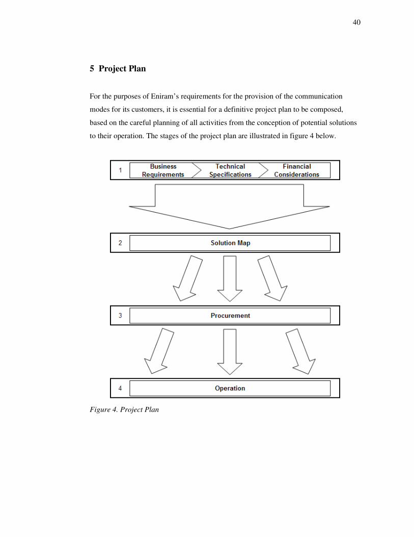
For the purposes of Eniram’s requirements for the provision of the communication
modes for its customers, it is essential for a definitive project plan to be composed,
based on the careful planning of all activities from the conception of potential solutions
to their operation. The stages of the project plan are illustrated in figure 4 below.
Figure 4. Project Plan
41
As can be seen from figure 4, the first stage is to state the considerations and restrictions
in selecting appropriate solutions by analysing Eniram’s and its customers’
requirements on general business, technical and financial levels. This is a once-only
activity at the beginning of the project and need not be repeated for every customer of
Eniram.
With the initial analysis in place, the second stage can be initiated, comprising the
creation of the Solution Map, a single document which will assist Eniram personnel in
effectively identifying the correct type of solution for a particular customer and their
data requirements.
If the solution identified by the Solution Map requires a new installation, then the
procurement stage can commence by sending Requests for Quotes (RFQs) to
appropriate suppliers, the replies to which are then evaluated and the successful
company selected. When a solution incorporates existing communications equipment
aboard a vessel, the procurement stage is obviously not required, but the implementation
of the solution still needs to be considered in the operational stage.
The operational stage takes into consideration important factors in the implementation
of the chosen solution, including (if necessary) site surveys, shipping and delivery,
installation, acceptance testing and commissioning, training and documentation. The
operational stage also consists of support and maintenance arrangements.
5.1 Business Requirements
On the business level, a statement is needed that defines the problem, the desired results
and the method for achieving them. Through discussions with Eniram personnel, the
business requirements were determined and are presented below.

42
Eniram requires a study into different telecommunication services for realising remote
ship-to-shore data connections for the purposes of communicating with its VMS
modules. Appropriate telecommunication services need to be evaluated in order to
confirm that they are able to fulfil the requirements of the three communication modes
identified by Eniram: RR, RD and RDM.
Eniram’s customers, specifically shipping operators who have ordered Eniram’s vessel
management solutions, will specify which communication modes they wish to purchase,
according to their individual management needs. Therefore, documentation is necessary
in order to aid Eniram in its decision-making processes when selecting and
implementing the appropriate telecommunications service for each customer.
Eniram’s customers will ultimately benefit from the improvements in their vessels’
performances attained through the installed VMS modules, therefore it is paramount
that the data obtained from Eniram’s systems are communicated to them in as efficient
and economical method as possible. Various factors require consideration when applied
to a ship’s data communication requirements, as outlined below [Leino V & Pyörre J,
Eniram Ltd, 19 June 2008, personal communication]:
Firstly, the type of vessel has a bearing on its data communications capabilities in that a
large cruise ship is invariably much better equipped for satellite Internet connectivity,
purely because of the ship’s scale and the communications demands of its corporate
functions and the expectations of its paying passengers; compared to a cargo ship which
traditionally would only operate a satellite connection for emergency purposes. This
means that in the event of a high-bandwidth satellite connection requirement, gaining
permission and successfully utilising an already existing communications system would
be easier to achieve on a cruise ship than a cargo ship. On gaining a new customer and
establishing their requirements, Requests for Information (RFIs) can be sent by Eniram
in order to ascertain what communication systems are already installed on the
customer’s ships and whether they can be utilised.

43
Secondly, the geographical areas of operation of each vessel directly dictate the types of
communication services that can be used and the frequencies and timeframes of when
communication can occur. For example, a vessel operating predominantly in the Arctic
regions will not be able to employ a satellite system that operates via geostationary
satellites because of their poor beam coverage of the polar regions. Instead, a satellite
system employing LEO or MEO satellites, with polar coverage, will need to be
considered.
Furthermore, when for example a PLMN communication requirement is identified, the
geographical route of a vessel and the times at which it is located within a base station’s
coverage area becomes important. The route of a passenger ferry between Helsinki and
Stockholm remains on the most part close to land and hence maintains good mobile
phone network connectivity, whereas an intercontinental cargo vessel will be out of
coverage for long periods of time. In the latter case, data transmission will only be
possible when the vessel is approaching or at a port of call, and the time period between
ports may be as high as three weeks; unless an MSS is employed.
5.2 Technical Specifications
With the business requirements clearly defined, the technical issues can then be
addressed by stating the purpose, functions and details of the various possible solutions
and their capabilities. This involves answering questions on their intended uses,
applications, access issues, capacities, inter-operability issues and performance
parameters.
The technical specifications are the principal sources of information for composing the
RFQs, sent to prospective suppliers of the various solutions during the procurement
stage. The information contained in the RFQs should sufficiently aid the prospective
suppliers in understanding exactly what solution is required and their returned quotes
will state how they are able to fulfil the requirements and the costs involved.

44
Furthermore, a full or partial approach to producing the technical specification must be
chosen. A full specification involves rigidly detailing the requirements in order to
tightly control the solution possibilities. The disadvantages of this approach are that it
can reduce the number of prospective suppliers and narrows the opportunities for them
to suggest creative alternatives, as well as placing the responsibility of the correct
implementation on the purchaser. It is more advantageous to employ the partial
approach whereby the technical requirements are stated in looser terms so that
prospective suppliers can use their own creativity in providing their solution proposals.
Important performance factors for consideration and inclusion in the technical
specifications are detailed are outlined in table 10 below.

45
Table 10. Factors for inclusion in technical specifications
Various factors displayed in table 10 will also become relevant during the composition
of the Solution Map.

46
5.3 Financial Considerations
As well as serving the communications needs, the solution needs to be economical to
purchase and operate. In considering the costs and expenses of the solution, it is prudent
to account for all expenditures over its whole lifetime. This includes the solution’s
initial costs: procurement, delivery, implementation and user training; its running costs:
operation, support, maintenance, repair, human resources and logistical costs; and the
teardown costs: decommissioning, disposal and replacement. It is then helpful to divide
these costs into one-time or recurring categories to illustrate how the cost of the solution
is distributed over time, as displayed in table 11 below.
Table 11. Possible one-time and recurring costs
One-Time Recurring
Design and engineering Bandwidth
Site survey Service provider charges
Purchase of equipment Power
Shipping Service and maintenance
Installation and commissioning Monitoring and evaluation
Activation User support
Spares Project management
Technical and user training
Much of the cost information shown in table 11 will derive from the suppliers’ quotes.

47
5.4 Solution Map
In creating the Solution Map, the issues raised in the initial analysis together with the
evaluations of possible communication services are consolidated into a single
document, in the form of a decision table, which will assist Eniram personnel in
effectively identifying the correct type of solution for a particular customer and their
data requirements. Generally, a decision table is a visual and analytical decision support
tool which is simple to understand and interpret by displaying the principal factors
involved in the decision process for selecting and introducing a new solution.
The Solution Map has to cover all conceivable communication requirements and can be
followed logically through a series of conditions and decisions, in order to reach the
most suitable type of solution for a particular customer. It is intended as a universal tool,
in that it can be consulted for each prospective customer as a starting point in
identifying their ideal solution.
From the initial analysis of the functional and technical requirements of a general
solution, preliminary conditions can be collected as a basis for the creation of the
Solution Map. These conditions and their bearings on the decision process are displayed
below in table 12.

48
Table 12. Preliminary conditions of solution map
From the preliminary conditions in table 12, most importantly, the volume of data
created per voyage is ascertained, as well whether a ship’s existing communication
systems can be utilised for the transfer of data and the geographical route of the ship. If
it is possible to utilise an existing communication system aboard a ship, then it will be
required to establish the total bandwidth capability of that system and how much of it is
available for Eniram’s use, as well as how often a data connection is possible due to the
ship’s route.

49
If a ship owner permits the use of existing communications systems, usage of them will
typically be limited by firewalls and filters, especially when large internal networks
exist for a vessel [Leino V, Eniram Ltd, 9 September 2008, personal communication]. It
may also be necessary for separate permission to be obtained from a shipping company
if a bidirectional link is required to a vessel, due to Eniram’s experience of facing
reticence on the part of some companies in allowing such capabilities for security
reasons [Pyörre J, Eniram Ltd, 14 October 2008, personal communication].
If all necessary permissions are granted and there is sufficient bandwidth and
opportunities to transfer Eniram’s VMS data, then the implementation of the
communication solution can commence. If, however, it is not possible to utilise any
existing communications services aboard a ship, due to no permission or insufficient
bandwidth capabilities, then it will be required to consider the installation of a new
communication service. This process will also be part of the Solution Map and will be
based on the evaluations of different services, the result of which will determine the
prime communication service for Eniram’s purposes according to the outcomes of the
preliminary conditions.
5.5 Procurement
For each customer, once a suitable type of solution has been identified using the
Solution Map, a competitive approach to procurement will be followed by sending
RFQs to multiple prospective suppliers. The returned suppliers’ quotes will be
compared with each other in order to ascertain the most effective and economical
solution for the customer’s requirements.
It may be possible to purchase the solution as a complete service, whereby a single
supplier can provide the whole solution, or as a component service, whereby different
parts of the solution are provided by different suppliers.

50
A sufficient evaluation scheme needs to be defined in order to compare the different
quotes received from suppliers, incorporating unambiguous business, technical and
financial criteria. Mandatory criteria that have to be met by a supplier should include the
experience of supplier, the financial standing of the supplier and equipment guarantees.
Other, non-mandatory, criteria are used to compare the quality of the proposed solutions
and include: the overall performance of the proposed communications link in
comparison with the requirements laid out in the technical specifications; the technical
characteristics of the terminal equipment; the quality of the implementation schedule to
meet the target dates set for receiving services; and the quality of the proposed
acceptance testing and commissioning plan.
On passing all criteria, a proposal shall be accepted on the basis of a combination of its
promised technical performance and its financial attractiveness.
5.6 Operation
When the supplier has been selected, the implementation and operation of the solution
can commence. The creation of an implementation plan with a carefully reviewed
schedule will ensure that all activities, resources, roles and responsibilities of Eniram
and supplier personnel are clear and attainable.
The implementation of the solution consists of site surveys, shipping and delivery,
installation, acceptance testing and commissioning, and training and documentation,
each with various considerations as listed below.
51
Site Survey: In the case of having to install new communication equipment onboard the
vessel, the ADU and BDU have to be located according strict considerations. Therefore,
it is important to have access to ship drawings to aid in undertaking detailed surveys of
the installation sites for each vessel. The main considerations in siting the equipment
are: an unobstructed line of sight for the antenna in order to track the direction of the
satellite; the avoidance of interference between the frequencies used by the satellite
equipment and those of other onboard systems; the cabling distance between the
outdoor antenna and the BDE needs to be within a specified limit.
Shipping and Delivery: A logistical problem occurs in the delivery of the equipment to
each vessel, in that a suitable port will need to be selected from each vessel’s route
itinerary and the equipment will need to arrive there punctually, wherever the vessels
are in the world. Other considerations include: deciding on air or sea freight, insurance
and customs clearance. It should be established as to who is responsible for the customs
issues and inevitable delays taken in to consideration, especially as delivery will be
made to different countries with varying customs regulations.
Installation: Where the solution supplier isn’t local to the installation port, as will
invariably be the case, the cost of installation can increase considerably due to flights
and accommodation for installation personnel. To avoid this, if possible, it should be
insisted in the RFQ that any prospective provider use local labour for site surveys,
installation and commissioning. The different tasks involved in installing the solution
include: assembly, antenna mounting, BDE installation, cabling and connections,
power-up, device configuration and tracking system setup.
Acceptance Testing and Commissioning: After installation, the solution should be
verified as working in compliance with all technical specifications, with the correct
integration of all system components in order to provide end-to-end connectivity. This
is achieved through acceptance testing consisting of a battery of acceptance tests and
their procedures, typically agreed on with the supplier prior to the solution’s acquisition.
A sufficient timeframe will be required after installation in order to confirm the correct
operation of the solution and perform any fine-tuning, before signing off with the

52
supplier. Common acceptance testing procedures include: powering the system to
ensure all equipment starts up, testing the communications link for the ability to receive
and transmit data, and testing for correct routing and network connections.
Training and Documentation: Detailed documentation of the overall solution and how
its components interface will be required by Eniram personnel, as well as manuals for
all items of installed equipment. Additionally, a decision will need to be made on how
many Eniram personnel will receive basic training on the solution’s installation and
operation, preferably on site during the installation phase, so that a knowledgeable core
of people is created with efficient problem-solving skills and the ability to realise any
other changing operational issues.
Post-implementation, the operational life of the solution is mainly concerned with
support and maintenance issues listed below.
Bandwidth Monitoring: This involves measuring the amount of bandwidth received
from the service provider and how much of that is used, as well as studying the usage
patterns. This will ensure that Eniram will get the exact amount of bandwidth that was
specified, help keep track of the bandwidth’s performance, i.e. any down periods, and
help make informed decisions on any changing bandwidth requirements.
Maintenance and Technical Support: The maintenance of equipment and systems
involves performing actions to correct a fault or prevent faults from occurring, and
includes repairs, upgrades, diagnostics and trouble shooting. With the RDM
communication mode in place, this will be possible remotely from the Eniram office.
Otherwise, any maintenance will require a physical presence at the installation site, in
which case it should be decided whether the maintenance should be performed by a
trained Eniram technician, a technician from the supplier or an external technician.
Technical support involves aiding users to resolve any problems by themselves through
advice given via telephone or email, and therefore does not require physically visiting
the site.

53
6 Solution Map
From the discussion of preliminary conditions in section 5.4, certain factors that will be
implemented in the Solution Map (SM) need to be defined. These factors can be divided
into four sections: communication factors, geographical factors, equipment factors and
cost factors; and the information therein will significantly aid the process of following
the SM. The information gathering process required of Eniram for each installation,
which will ascertain the aforementioned factors, is presented in the Information Map
(IM). The IM consists of four sections, labelled IM1 to IM4, which are presented in
appendix 1 and described below.
IM1: Volume of Data Generated per Module and Communication Mode
In anticipation of Eniram’s requirement to calculate expected data rates produced by the
modules and the available data rates of the various communications systems aboard a
vessel, a worthwhile exercise would be to collate expected volumes of data generated
for each of Eniram’s modules according to which communication mode is employed.
This can be done through experience of existing performance data as well as through
predictions, and can be recorded in terms of the data generated per hour or per day,
whichever is more appropriate. Individual modules and combinations of modules should
be considered as there is usually a base volume of data shared between modules as well
as possible additional volumes for each module [Pyörre J, Eniram Ltd, 14 October 2008,
personal communication]. When completed, IM1 will provide a quick reference for the
data volumes generated for particular combinations of Eniram modules and
communication modes, applicable to all new vessels ordering Eniram installations.

54
IM2: Geographical Areas of Operation
Information can be collated on each vessel’s area of operation, listing the ports of call
during a voyage, the durations of each leg and, hence, the estimated volume of data
generated during each leg according to the information recorded in the IM1 multiplied
by the duration. When communications systems other than MSSs need to be considered,
the route leg’s proximity to the coast and, hence, its coverage by a PLMN can be
determined, as well as the ship’s time at port during which it has access via a shore
connection or WLAN at each port facility.
IM3: Existing Onboard Communications Systems
Information can be collated on each vessel’s existing communications systems
according to whether it is an MSS, PLMN or port connection, the systems’ bandwidth
capabilities and the bandwidth available for Eniram’s use (uplink and downlink), the
times when Eniram can employ the system, and whether permission to use the system
has been granted. An IM3 can be created for each vessel and the information contained
can also be applied to new vessels with matching systems.
IM4: Data Transfer Costs of Onboard Communications Systems
With the information recorded on each vessel’s IM3 regarding existing communications
systems, their respective costs can be recorded on a vessel’s IM4. Factors consist of the
type of connection cost tariff (on a per unit time or per unit volume of data basis), the
actual rate charged for the connection, and any relevant notes. An IM4 can be created
for each vessel and the information contained can also be applied to new vessels with
matching systems.
The Solution Map tabulates the steps needed in the decision process and incorporates
the factors compiled in the Information Maps as the rationale behind different choices
and comparisons in the process. The final Solution Map is divided into eight logical
sections, labelled SM1 to SM8, and is presented in appendix 2.
55
7 Conclusion
The key outcomes of the project were the production of the Information Map and the
Solution Map. The IM is in questionnaire form and divided into four sections, detailing
the information necessary to be gathered on each vessel installation in terms of
communication requirements, geographical operations, existing onboard systems and
communication costs. The SM provides steps to the user on how to process the
information attained and use the resulting factors in forming a decision on the most
appropriate method of communications for each particular installation. The project also
introduced key characteristics of the different communications methods available for
ship-to-shore data connections as a theoretical background to the decision-making
process.
With the information gathering process in place, the IMs will grow into a database of
vessels and thereby prove useful as a reference tool for when new customers and vessels
apply for Eniram’s services. The SM has been verified as logically illustrating the main
decisions in a solution implementation, and when adopted in the beginning of 2009 it
should provide a singular, standardised method for all personnel.
Suggested methods for furthering this project would be to begin the completion of the
IMs for Eniram’s existing vessel installations, thereby highlighting any possible
changes that may need to be made in terms of presentation and extra information. With
the up-to-date IMs in place, the SM can be executed on a number of existing vessels so
as to test its effectiveness and compare the suggested outcomes to the actual solutions
installed. Furthermore, the construction of a database of communications providers and
operators could also commence, arranged into their geographical areas of operation,
service data rates, costs, and roaming charges, facilitating the overall procurement
process.

56
References
1 Company [online]. Helsinki, Finland: Eniram Ltd.
URL: http://www.eniram.fi. Accessed 26 November 2008.
2 Elbert BR. Introduction to satellite communication. 2nd ed. Norwood, MA:
Artech House; 1999.
3 Lutz E, Werner M, Jahn A. Satellite systems for personal and broadband
communications. Berlin: Springer-Verlag; 2000.
4 Sadiku MNO. Optical and wireless communication: next generation networks.
Boca Raton, FL: CRC Press; 2002.
5 Inside the I-4 satellites: spot beams focus power [online]. London, UK: Inmarsat
plc.
URL: http://www.inmarsat.com/About/I-4_launch. Accessed 11 November
2008.
6 An overview of the Global Maritime Distress & Safety System. Alexandria, VA:
US Coast Guard Navigation Center.
URL: http://www.navcen.uscg.gov/marcomms/gmdss/default.htm. Accessed 1
July 2008.
7 International convention for the safety of life at sea (SOLAS). Consolidated ed.
London: International Maritime Organisation (IMO); 2004.
8 This is Inmarsat: pioneering and reliable [online]. London, UK: Inmarsat plc.
URL: http://www.inmarsat.com/About. Accessed 26 November 2008.

57
9 Cunningham P. FleetBroadband brings new dimension to maritime
communications [online]. Services, Maritime, FleetBroadband, Case Studies.
London, UK: Inmarsat plc; 15 November 2007.
URL: http://www.inmarsat.com/Downloads/English/FleetBroadband/
Case_Studies/Inmarsat_Imarest.pdf
10 FleetBroadband overview brochure [online]. Services, Maritime,
FleetBroadband. London, UK: Inmarsat plc; 25 September 2007.
URL: http://www.inmarsat.com/Downloads/English/FleetBroadband/Collateral/
FleetBroadband_overview_brochure_EN.pdf
11 Technical information Inmartsat Fleet F77 [online]. London: Inmarsat Global
Ltd; 24 June 2005.
URL: http://www.inmarsat.com/Services/Maritime/Fleet/F77. Accessed 19 May
2008.
12 Technical information Inmartsat Fleet F55 [online]. London: Inmarsat Global
Ltd; 24 June 2005.
URL: http://www.inmarsat.com/Services/Maritime/Fleet/F55. Accessed 19 May
2008.
13 Technical information Inmartsat Fleet F33 [online]. London: Inmarsat Global
Ltd; 24 June 2005.
URL: http://www.inmarsat.com/Services/Maritime/Fleet/F33. Accessed 19 May
2008.
14 Inmarsat maritime communications handbook (issue 4). London: Inmarsat;
2006.

58
15 SeaMobile acquires Maritime Telecommunications Network (MTN) [online].
Press room. Seattle, WA: SeaMobile Enterprises; 11 May 2006.
URL: http://www.seamobile.com/press/05_11_06.aspx. Accessed 21 October
2008.
16 Cruise brochure [online]. Market Solutions, Cruise Lines. Seattle, WA:
SeaMobile Enterprises; 19 February 2008.
URL: http://www.seamobile.com/market_solutions/cruisebrochure_proof2.pdf.
Accessed 21 October 2008.
17 Technology and networks [online]. MTN Global Networks. Seattle, WA:
SeaMobile Enterprises; 20 August 2008.
URL: http://www.seamobile.com/mtn_global_networks/lores_technology-and-
networks_a4.pdf. Accessed 21 October 2008.
18 VSAT equipment [online]. Equipment & Systems. Seattle, WA: SeaMobile
Enterprises; 20 August 2008.
URL: http://www.seamobile.com/equipment_systems/lores_vsat-
equipment_a4.pdf. Accessed 21 October 2008.
19 GSM coverage maps [online]. London, UK: GSM Association; 2008.
URL: http://www.gsmworld.com/technology/roaming/gsminfo. Accessed 23
October 2008.
20 Anttalainen T. Mobile communications. Helsinki: Metropolia University of
Applied Sciences; 2005.
21 Stuckmann P. The GSM evolution: mobile packet data services. Chichester, UK:
John Wiley & Sons; 2003.
22 Seurre E, Savelli P, Pietri P-J. EDGE for mobile Internet. Norwood, MA: Artech
House; 2003.

59
23 About mobile technology and IMT-2000 [online]. Geneva: International
Telecommunication Union; 1 December 2005.
URL: http://www.itu.int/osg/spu/imt-2000/technology.html. Accessed 3
November 2008.
24 Kreher R, Rüdebusch T. UMTS signaling. 2nd ed. Chichester, UK: John Wiley
& Sons; 2007.
25 CDMA2000: market trends and facts [online]. Costa Mesa, CA: CDMA
Development Group (CDG); 6 September 2008.
URL: http://www.cdg.org/technology/3g/resource/
CDG_MarketTrendsFacts_English.pdf. Accessed 5 November 2008.
26 Frequently asked questions. Beaverton, OR: WiMAX Forum; 2008.
URL: http://www.wimaxforum.org/documents/faq. Accessed 26 November
2008.
27 Nuaymi L. WiMAX: technology for broadband wireless access. Chichester, UK:
John Wiley & Sons; 2007.
28 Schmidt R. 65 million CAT-iq home gateways in 2012 [online]. Berne,
Switzerland: DECT Forum; 13 November 2008.
URL: http://www.dect.org/UserFiles/file/Press%20releases/
CAT-iq_Press%20Information_Market%20Forecast_11192008.pdf. Accessed
26 November 2008.
29 Towards global mobile broadband [online]. White paper. London: UMTS
Forum; 8 February 2008.
URL: http://www.umts-forum.org. Accessed 6 November 2008.
30 Requirements for further advancements for E-UTRA (LTE-Advanced). Sophia
Antipolis, France: 3rd Generation Partnership Project; 10 June 2008.

60
31 Global mobile broadband: market potential for 3G LTE [online]. Report for
UMTS Forum. London: Analysys Research Ltd; 20 January 2008.
URL: URL: http://www.umts-forum.org. Accessed 6 November 2008.
32 O’Hara B, Petrick A. IEEE 802.11 handbook: a designer’s companion. 2nd ed.
New York, NY: IEEE Press; 2005.
33 Ilus T. Vessel management platform for comprehensive improvements [online].
Solutions. Helsinki, Finland: Eniram Ltd; 21 December 2007.
URL: http://www.eniram.fi/images/stories/Material/
VesselManagementPlatform.pdf. Accessed 20 April 2008.
34 Dahl H. Eniram: short introduction and status report. Company meeting
presentation. Helsinki, Finland: Eniram Ltd; 12 May 2008.
35 Dynamic stability monitor for safe voyages. Information sheet. Helsinki,
Finland: Eniram Ltd; 2008.
36 Ilus T. Cargo Securing Monitor – minimising cargo damage. Information sheet.
Helsinki, Finland: Eniram Ltd; 11 March 2008.
37 Ilus T. Comfort factor monitor for passenger revenue [online]. Solutions, Safety
& Comfort, CFM. Helsinki, Finland: Eniram Ltd; 27 November 2007.
URL: http://www.eniram.fi/images/stories/Material/ComfortFactorMonitor.pdf.
Accessed 20 April 2008.
38 Ilus T. Extended safety management system [online]. Solutions, Safety &
Comfort, E-SMS. Helsinki, Finland: Eniram Ltd; 27 November 2007.
URL: http://www.eniram.fi/images/stories/Material/
ExtendedSafetyManagementSystem.pdf. Accessed 20 April 2008.

61
39 Ilus T. Dynamic trimming assistant for fuel efficiency [online]. Solutions,
Performance, DTA. Helsinki, Finland: Eniram Ltd; 30 November 2007.
URL: http://www.eniram.fi/images/stories/Material/
DynamicTrimmingAssistant.pdf. Accessed 20 April 2008.
40 Ilus T. Hull roughness monitor for timely brushing. Information sheet. Helsinki,
Finland: Eniram Ltd; 11 March 2008.
41 Ilus T. Vessel emission tracker for environmental values [online]. Solutions,
Emissions, VET. Helsinki, Finland: Eniram Ltd; 27 November 2007.
URL: http://www.eniram.fi/images/stories/Material/VesselEmissionTracker.pdf.
Accessed 20 April 2008.

62
Appendix 1: Information Map
Appendix 1 contains the Information Map as described in chapter 6, the different
sections of which are listed below in the order they appear.
IM1: Bandwidth requirements per communication mode and module
IM2: Geographical area of operation
IM3: Existing onboard communications systems
IM4: Data transfer costs of onboard communications systems
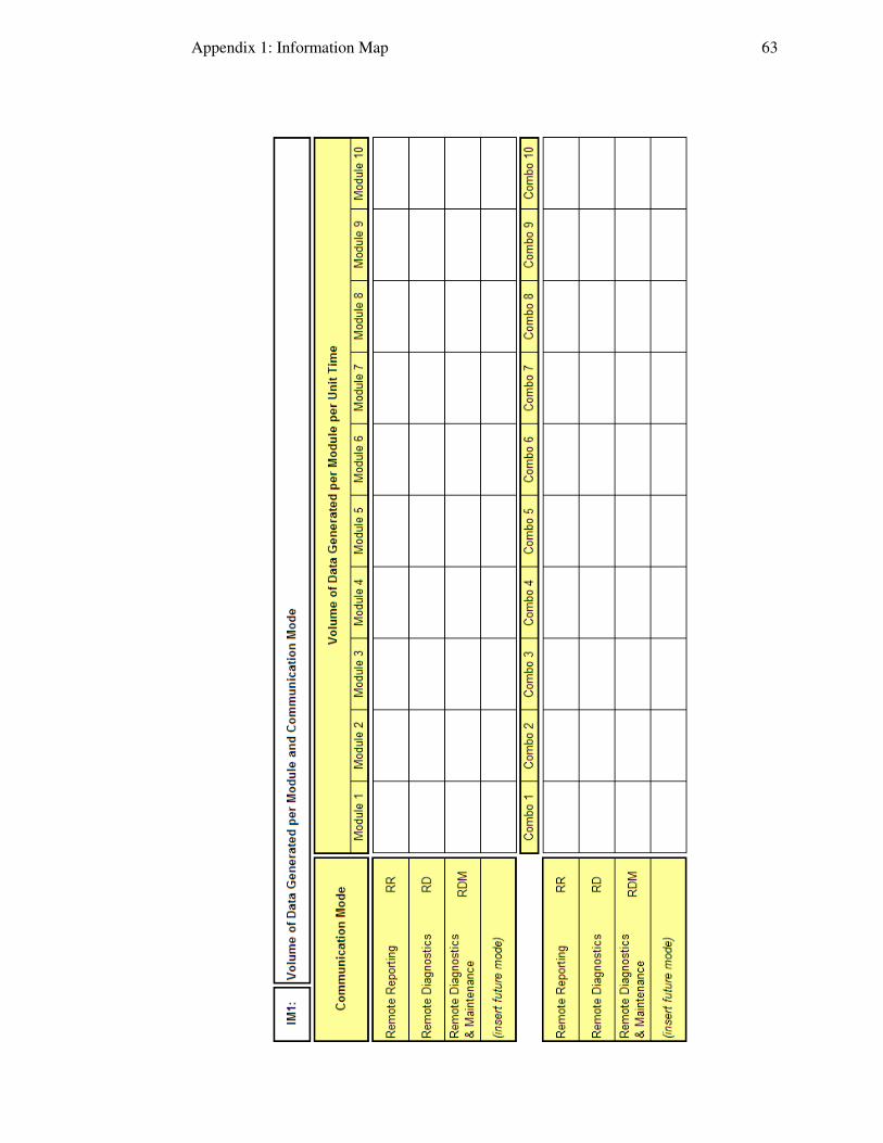
Appendix 1: Information Map 63

Appendix 1: Information Map 64

Appendix 1: Information Map 65

Appendix 1: Information Map 66

67
Appendix 2: Solution Map
Appendix 2 contains the Solution Map as described in chapter 6, the different sections
of which are listed below in the order they appear.
SM1: Identify Customer Order
SM2: Complete Information Maps (IM2-IM4)
SM3: Inspect Existing Onboard Communications Systems
SM4: Compare Performances of Existing Onboard Communications Systems
SM5: Select Existing Onboard Communications Systems to employ for solution
SM6: Collect Information on Prospective Communications Providers
SM7: Select New Communications System to employ for solution
SM8: Update Information Maps

Appendix 2: Solution Map 68

Appendix 2: Solution Map 69

Appendix 2: Solution Map 70