SALMONID PASSAGE A~•STREAM-ROAD CROSSINGS
81
SALMONID PASSAGE CROSSINGS A Report with Department Standards for Passage of Salmonids By Jim E. Lauman Staff Biologist Environmental Management Section William E. Pitney, Head Department of Fish and Wilulife John R. Donaldson, Director Portland, Oregon 1976
Transcript of SALMONID PASSAGE A~•STREAM-ROAD CROSSINGS
SALMONID PASSAGE A~•STREAM-ROAD CROSSINGS
A Report with Department Standards
for
Passage of Salmonids
By
Jim E. Lauman Staff Biologist
Environmental Management Section William E. Pitney, Head
Department of Fish and Wilulife John R. Donaldson, Director
Portland, Oregon
1976

n ~-)
£\ ~j
1'=-~i ( -'
"--=/
JUN i 1982
AL AS'!(A D!:\i'<Hf:t/'cr I ! on A DV iA • . ·~ l ·'!;·· 0,<' \ '\ ' '~"'''- 0~;\ I D ~ Iii '.:.,.,-">dJ"!:,.;- .,.,.,,;:.'6--l'co""o:.g tk.o&. ~f ~ :.~
U.S. Depai'tment of tn~ Interior
TABLE OF CONTENTS
INTRODUCTION • • • • • • • • • • • • • • • • • • • • •
DEPARTMENT OF FISH AND WILDLIFE STANDARDS • • • • • • •
FISH PASSAGE PROBLEMS AND SOLUTIONS • • • • • • • • • •
Excessive water velocity Problem • • • • • Cause • • Solution •
• •
• • • •
Inadequate water depth Problem • • • • Cause • • • • • Solution • • • •
• •
• • •
• • •
• • • •
Excessive entrance jump • Problem • • • • • • cause • • • • • • • Solution • • • • • •
• • • • • • • • • • • • • • • • • • • • • • • • • • • • • • • • • • • • • • • • • • • • • • • • • • • •
• • • • • • • • • • • • • • • • • • • • • • • • • • • • • • • • • • • • • • • • • • • • • • • • • • • •
• • • • • • • • • • • • • • • • • • • • • • • • • • • • • • • • • • • • • • • • • • • • • • • • • • • •
GUIDELINES FOR STRUCTURES ••••••••••••••••
Location • • • • • • • • • • • • • • • •
Type • • • • • • • • • • • • • • • • • •
Structure size • • • • • • • • • • • • •
Miscellaneous • • • • • • • • • • • • • •
REFERENCES • • • • • • • • • • • • • • • • • •
TABLES
1. Recommended maximum water velocity in culverts for adult fish passage • •
• • •
• • •
• • •
• • •
• • •
• • •
2. Best water velocities for passage of adult fish • • • • • • • • • • • • • • • • • • •
•
•
•
•
•
•
•
3. Roughness factors for various type channels
FIGURES
•
•
•
•
•
•
•
•
1. Recommended maximum velocities for upstream passage of juvenile salmonids • • • • • • • •
2. Approved baffled culvert design • • • • • • •
3. Recommended design of weirs for backflooding culverts • • • • • • • • • • • • • • • • • • •
i
Page
1
1
4
4 4 7 8
16 16 16 16
17 17 18 18
20
20
21
24
25
26
3
6
7
5
9
13
TABLE OF CONTENTS (continued)
4. Weir construction used to improve fish passage at mouth of Gold Creek, West Fork Smith
5.
6.
7.
APPENDICES
1.
2.
3.
4.
5.
River. • • • • • • • • • • • • • • • • • • • •
Change of culvert slope or partial backflooding can place the location of maximum velocity at a point other than the outlet. • • • • • • • •
Jumps at structure outlet caused by "A" degraded channel and "B" by placing structure on a grade considerably flatter than streambed. • • • • •
Apron under bridge may cause unsuitable fish passage condition. • • • • • • • • • • • • • •
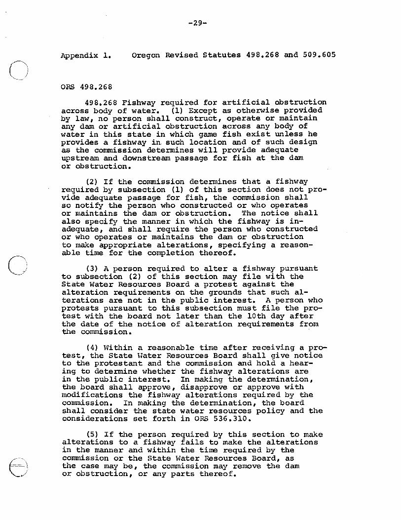
Oregon Revised Statutes 498.268 and 509.605 ••
Salmon energy efficiency curve • • • • • • • •
Vertical drops are preferred over sloped drops • • • • • • • • • • • • • • • • • • • •
Recommended depth to countersink arch pipe culverts • • • • • • • • • • • • • • • • • • •
Calculation of velocity and water depth through culverts of various types • • • • • • • • • •
ii
Page C',,
14
15
19
23
29
31
32 C',_ 33
34
c~'
(~\
\ I "-..___.~//
r~_; c/
( -__ -\,
~J
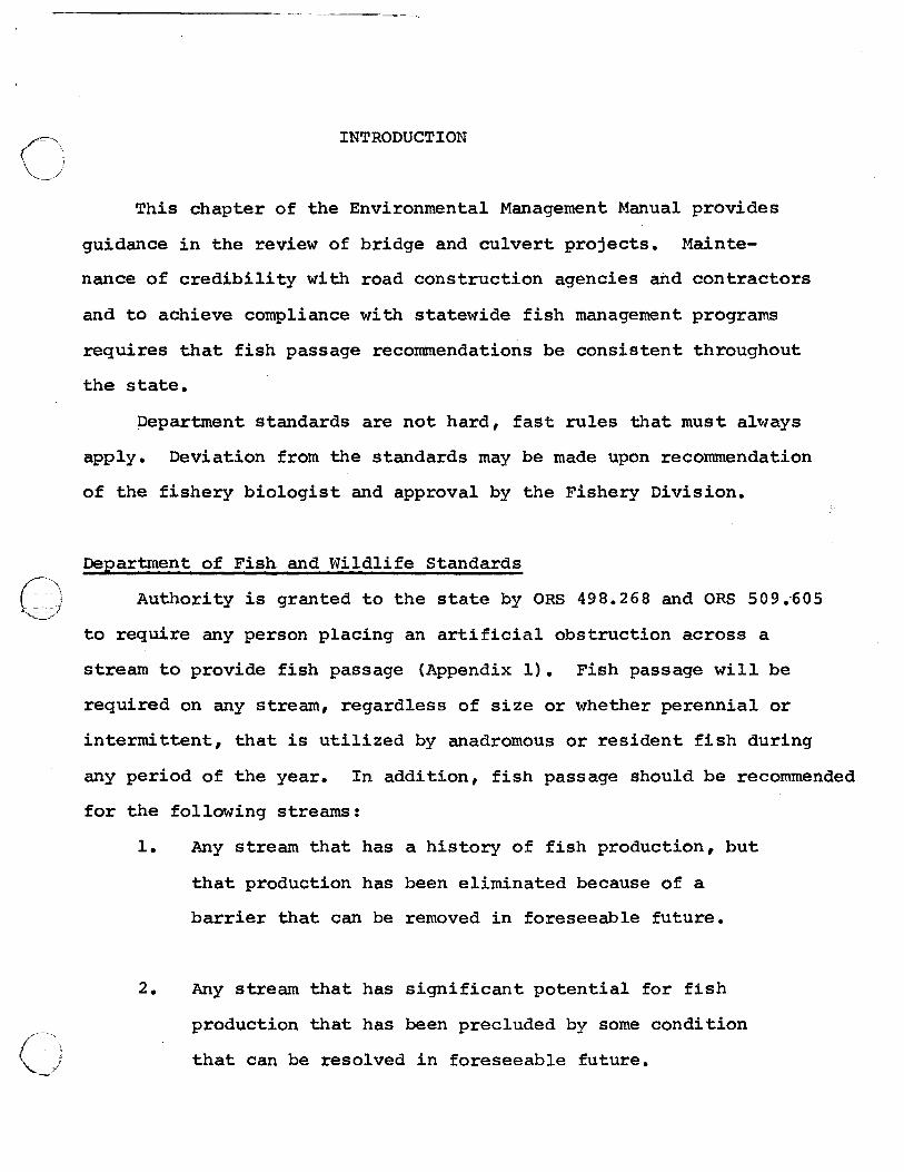
INTRODUCTION
This chapter of the Environmental Management Manual provides
guidance in the review of bridge and culvert projects. Mainte
nance of credibility with road construction agencies and contractors
and to achieve compliance with statewide fish management programs
requires that fish passage recommendations be consistent throughout
the state.
Department standards are not hard, fast rules that must always
apply. Deviation from the standards may be made upon recommendation
of the fishery biologist and approval by the Fishery Division.
Department of Fish and Wildlife Standards
Authority is granted to the state by ORS 498.268 and ORS 509.-605
to require any person placing an artificial obstruction across a
stream to provide fish passage (Appendix 1). Fish passage will be
required on any stream, regardless of size or whether perennial or
intermittent, that is utilized by anadromous or resident fish during
any period of the year. In addition, fish passage should be recommended
for the following streams:
1. Any stream that has a history of fish production, but
2.
that production has been eliminated because of a
barrier that can be removed in foreseeable future.
Any stream that has significant potential for fish
production that has been precluded by some condition
that can be resolved in foreseeable future.
-2-
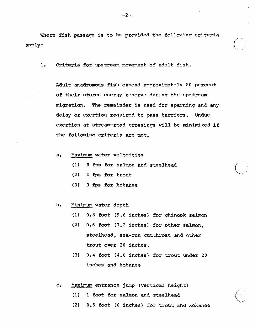
Where fish passage is to be provided the following criteria
apply:
l. Criteria for upstream movement of adult fish.
Adult anadromous fish expend approximately 80 percent
of their stored energy reserve during the upstream
migration. The remainder is used for spawning and any
delay or exertion required to pass barriers. Undue
exertion at stream-road crossings will be minimized if
the following criteria are met.
a. Maximum water velocities
(1) 8 fps for salmon and steelhead
(2) 4 fps for trout
(3) 3 fps for kokanee
b. Minimum water depth
(1) 0.8 foot (9.6 inches) for chinook salmon
(2) 0.6 foot (7.2 inches) for other salmon,
steelhead, sea-run cutthroat and other
trout over 20 inches.
(3) 0.4 foot (4.8 inches) for trout under 20
inches and kokanee
c. Maximum entrance jump (vertical height)
(l) l foot for salmon and steelhead
(2) 0.5 foot (6 inches) for trout and kokanee
c-,
(,' ,
E>
~! ------
-3-
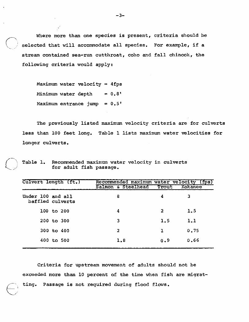
Where more than one species is present, criteria should be
selected that will accommodate all species. For example, if a
stream contained sea-run cutthroat, coho and fall chinook, the
following criteria would apply:
Maximum water velocity = 4fps
Minimum water depth = 0.8'
Maximum entrance jump = 0.5 1
The previously listed maximum velocity criteria are for culverts
less than 100 feet long. Table 1 lists maximum water velocities for
longer culverts.
o Table 1. Recommended maximum water velocity in culverts for adult fish passage.
€:
Culvert length (ft.) Recommended maximum water velocity (fps) Salmon & SteeineaC! Trout Koleanee
Under 100 and all 8 4 3 baffled culverts
100 to 200 4 2 1.5
200 to 300 3 1.5 1.1
300 to 400 2 1 0.75
400 to 500 1.8 o.9 0.66
Criteria for upstream movement of adults should not be
exceeded more than 10 percent of the time when fish are migrat-
ting. Passage is not required during flood flows.
-4-
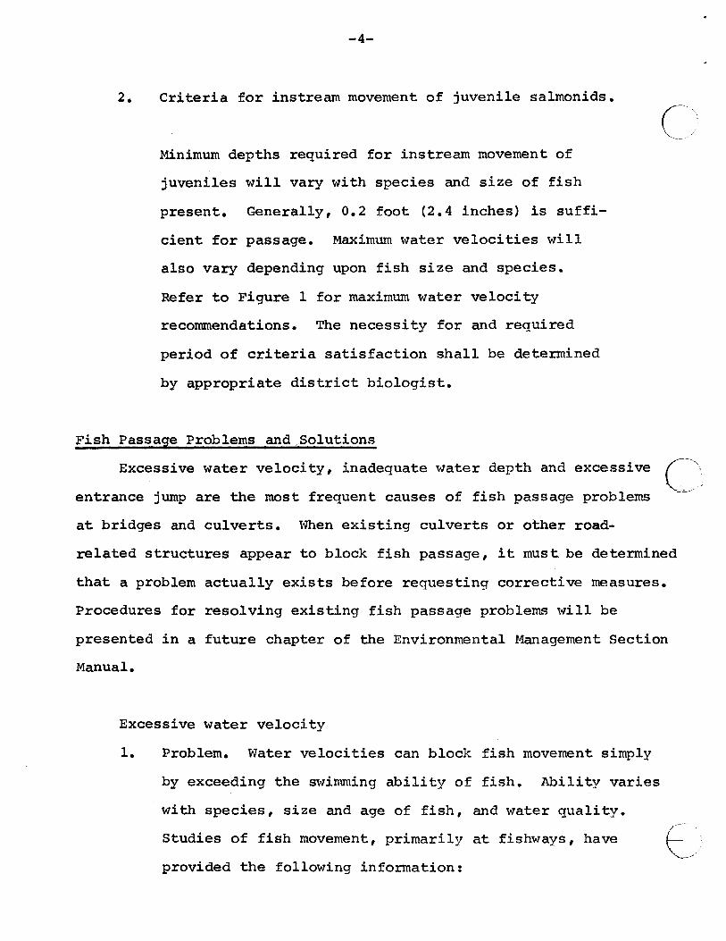
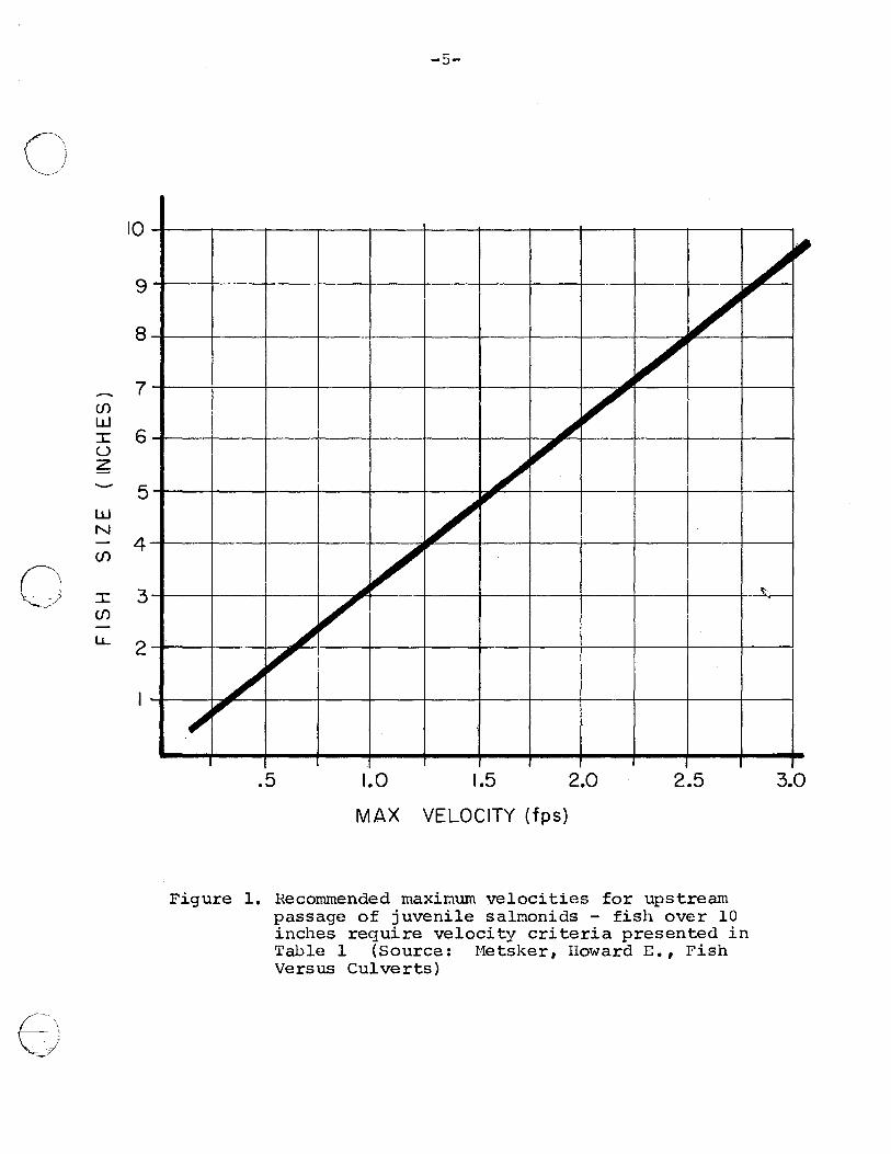
2. Criteria for instream movement of juvenile salmonids.
Minimum depths required for instream movement of
juveniles will vary with species and size of fish
present. Generally, 0.2 foot (2.4 inches) is suffi
cient for passage. Maximum water velocities will
also vary depending upon fish size and species.
Refer to Figure 1 for maximum water velocity
recommendations. The necessity for and required
period of criteria satisfaction shall be determined
by appropriate district biologist.
Fish Passage Problems and,Solutions
Excessive water velocity, inadequate water depth and excessive
entrance jump are the most frequent causes of fish passage problems
C~'
c·,\; at bridges and culverts. When existing culverts or other road
related structures appear to block fish passage, it must be determined
that a problem actually exists before requesting corrective measures.
Procedures for resolving existing fish passage problems will be
presented in a future chapter of the Environmental Management Section
Manual.
Excessive water velocity
1. Problem. Water velocities can block fish movement simply
by exceeding the swimming ability of fish. Ability varies
with species, size and age of fish, and water quality.
Studies of fish movement, primarily at fishways, have
provided the following information: ~/
~) ~"
10
9
8
7 Cf)
w I 6 u z
5 w N
Cf) 4
0 I 3 Cf) -u.. 2
f)
-5-
/ ~
/ ,
-
~ v ~ v
I / ,
v ""
~ v -~-v
~
/ ,,
~ ~
.5 1.0 1.5 2.0 2.5 3.0
MAX VELOCITY (fps)
Figure 1. Recommended rnaxi@um velocities for upstream passage of juvenile salmonids - fish over 10 inches require velocity criteria presented in Table 1 (Source: l·1etsker, Howard E. , Fish Versus Culverts)
a.
-6-
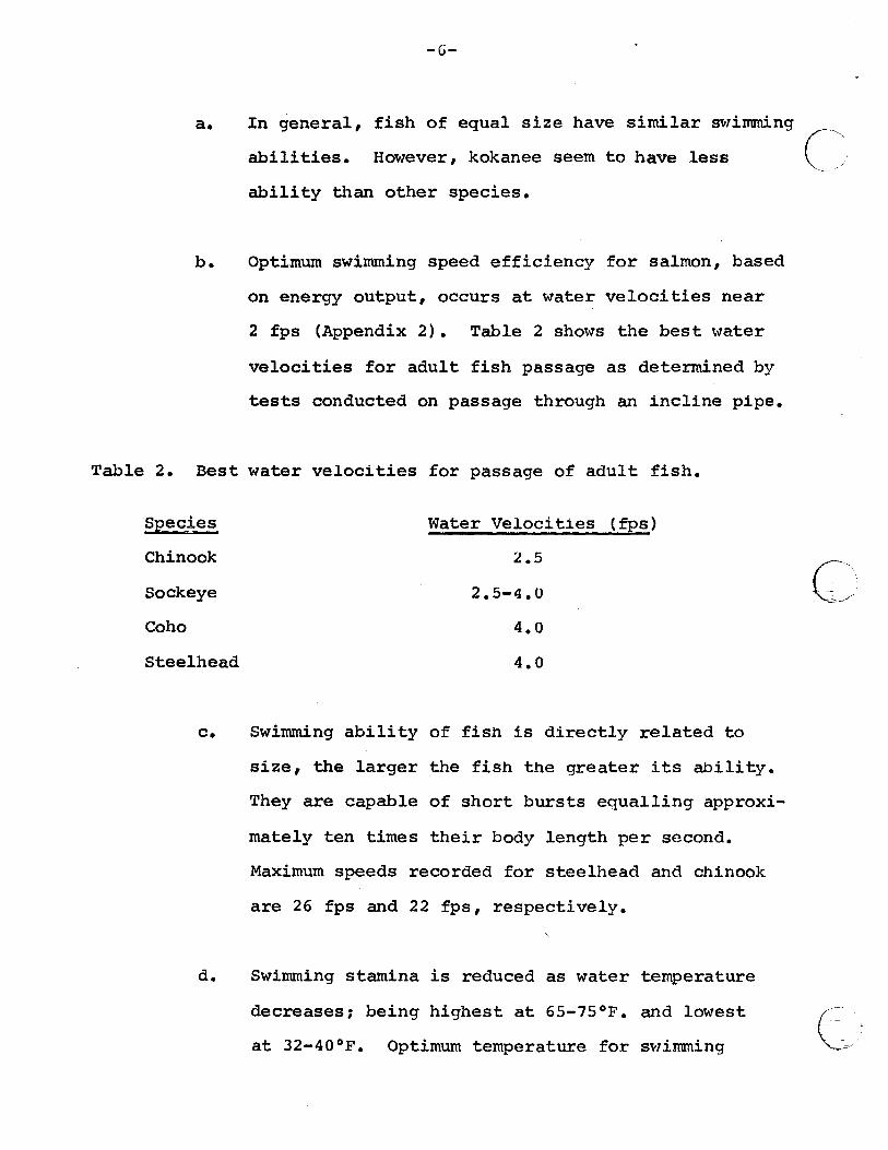
In general, fish of equal size have similar swimming
abilities. However, kokanee seem to have less
ability than other species.
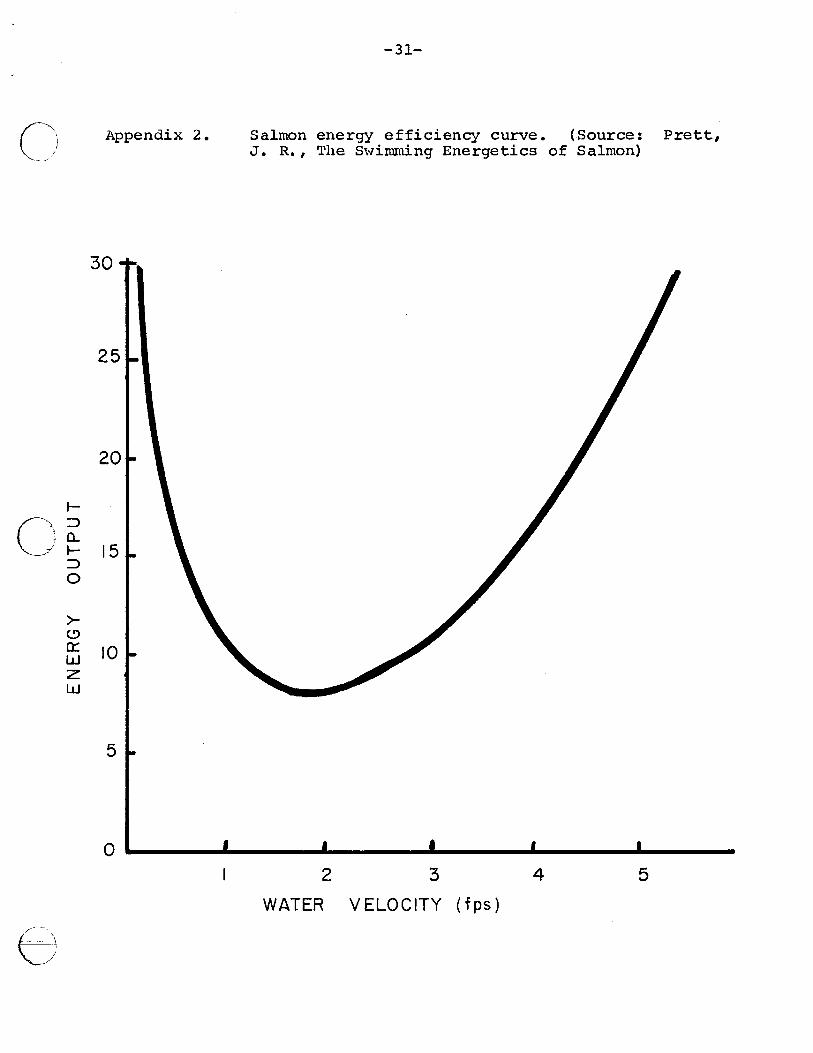
b. Optimum swimming speed efficiency for salmon, based
on energy output, occurs at water velocities near
2 fps (Appendix 2). Table 2 shows the best water
velocities for adult fish passage as determined by
tests conducted on passage through an incline pipe.
Table 2. Best water velocities for passage of adult fish.
Species
Chinook
Sockeye
Water Velocities (fps)
2.5
2.5-4.0
Coho 4.0
Steelhead 4.0
c. Swimming ability of fish is directly related to
size, the larger the fish the greater its ability.
They are capable of short bursts equalling approxi
mately ten times their body length per second.
Maximum speeds recorded for steelhead and chinook
are 26 fps and 22 fps, respectively.
d. Swimming stamina is reduced as water temperature
decreases; being highest at 65-75°F. and lowest
at 32-40°F. Optimum temperature for swimming
(' '----- '
C~ -·
e~,-
n "-----~/
0 ~
c;) ~~7
2.
-7-
ability of juveniles is 68°F. Atlantic salmon
and rainbow trout experience reduced movement and
jumping activity when water temperatures are less
than 42°F.
e. The amount of dissolved oxygen in the water contributes
to the swimming ability of fish. Changes in dissolved
oxygen concentrations from 7 mg/1 to 3 mg/1 can reduce
sustained swimming speeds by 500 percent.
f. Upstream migrants show a lack of movement during the
peak of freshets. Upstream movement is generally
highest on receding flows after freshets.
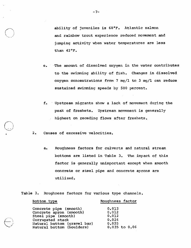
Causes of excessive velocities.
a. Roughness factors for culverts and natural stream
bottoms are listed in Table 3. The impact of this
factor is generally unimportant except when smooth
concrete or steel pipe and concrete aprons are
utilized.
Table 3. Roughness factors for various type channels.
Bottom type
Concrete pipe (smooth) Concrete apron (smooth) Steel pipe (smooth) Corrugated stack Natural bottom (gravel bar) Natural bottom (boulders)
Roughness factor
0.012 0.012 0.012 0.024 0.025 0.035 to 0.06
b.
-8-
Size of structure in relation to flm•T.
This factor has minimal importance in velocities
except when the structure is considerably under-
sized and a head is developed (pooling at upstream
end). In that case, the head causes higher veloci-
ties. Head should not be designed into projects
where fish passage is desired.
c. Slope.
(~'·
Slope is the most important factor determining velocity
in culverts. Slopes steeper than .s percent (1/2
foot drop in 100 feet) generally create excessive
velocities for fish passage.
3. Solution to excessive water velocity problems.
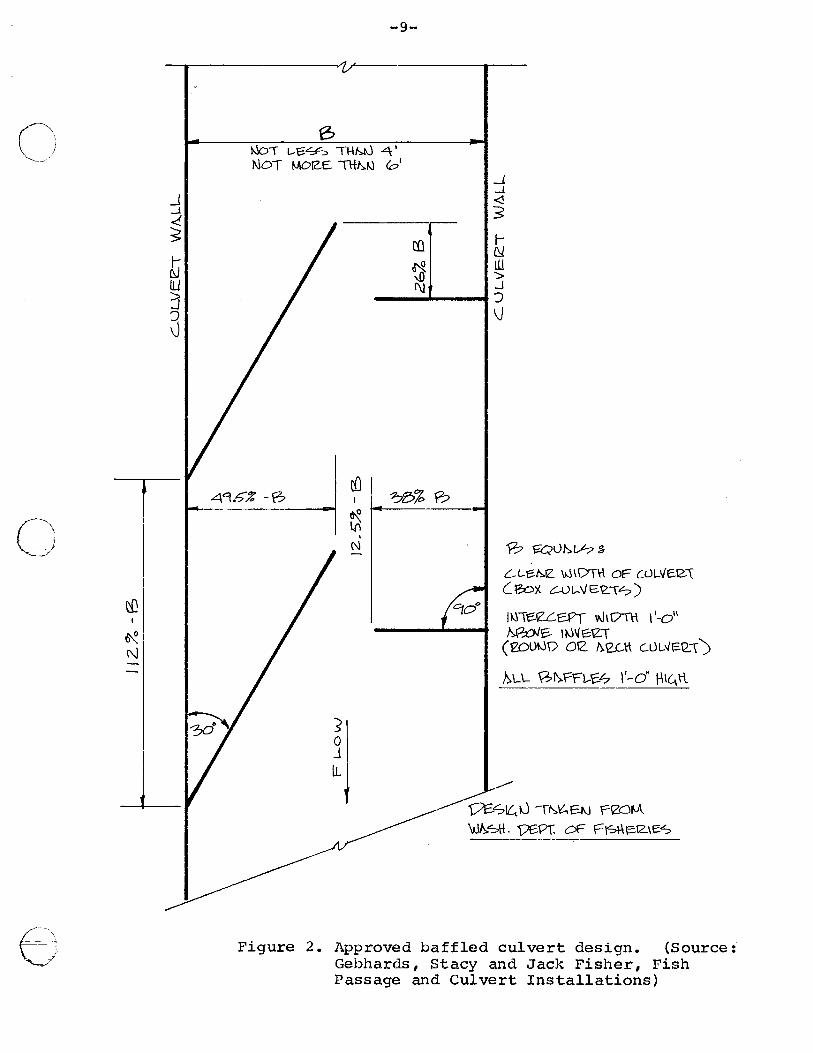
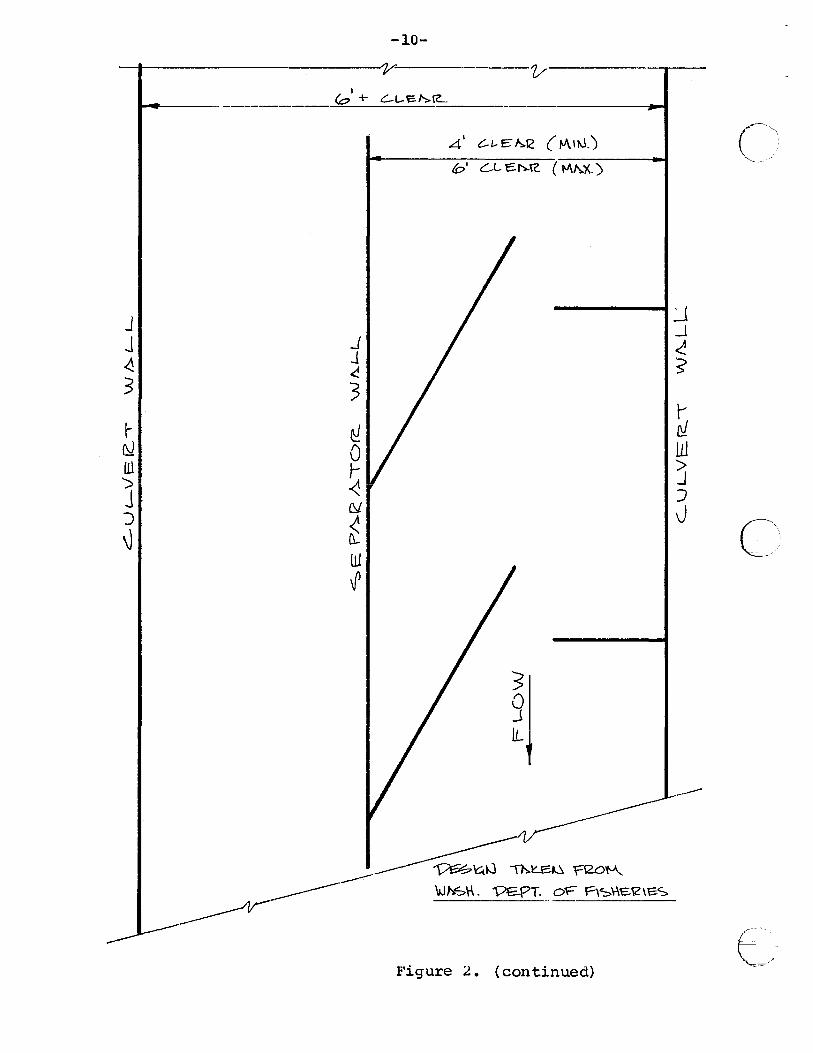
a. Properly designed baffles can reduce velocities in
culverts on slopes up to 5 percent (Figure 2). The
velocity is reduced because the path of flow is
lengthened (reduction of slope) and the roughness
factor is increased. Baffles are most effective
when they are just overtopped~ effectiveness drops
quickly as water depth increases beyond one foot
over baffle tops. Due to this variability in
efficiency, reduction of culvert flow capacity and
increased debris problems, baffles should only be
c\
~·· ....
~~/
C) '
0
F\. -'---../
_{ _.1
<. :s ~ lU 1 3
-9-
6 001 L-£0~ THMJ 4 I
NOT MDIZE. ll-t~~ 0' _J _.1
<! 3
Cfl ~ ~ ill '!) > !\} .J __ ...... __ ~J
\J
T 4q.,-~ ~I '?8% e::. - ~
l{i
~I I ~~
Nl I
LV
I
I N I I 0 mvt-:.Lh$
L-L-e:~IZ. W\DT\\ OF OJLI/£12-\ ( eox C-Ul-VE'2.1?)
/ I f'1ool ltJI~Ue.Pi ~hOTH. I'-d'
I l':R:OJ'C-- ltJ\fE::IZ\ ) I (eoutJo oe !).e_c..tt cu'-"~Q..\ !>LL Gl).rrt.-€.£7 \'-o" 1-\t~ r\.
I 5 0 J
~j ·-----
-----j/1-
\aJI>SH. V£91. c£ Fl'S\-\t:=-'12-\e:-'S> -------
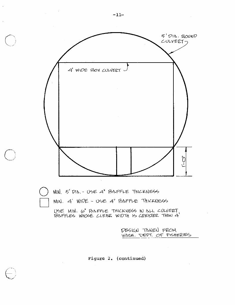
Figure 2. Approved baffled culvert design. (Source:· Gebhards, Stacy and Jack Fisher, Fish Passage and Culvert Installations)
-~ :: ..
(\ c r < m fJ -1
~ ? r r
(penu1':+ uoo) •?: e.:rn.51'd
J' rn
~ !\)
v---l 0 (V
f ;:> r I
(. ·y.:vw) 2l-<J"3/? .OJ --------'--
("f'll'rl) 21~ .31? ,v
~-------------------=-----------------11 G)<..J"a"1/ + 0) I
~ c r <-rn (\) 1
t V' r r
·---/t -----~-------------------+-
-at-
11? ('KJ\-\1.. 38.L"'~3'? <7\ \-\i-01 M '21'\J:::n/ ~\-\I'll 791d-.;:::1"10 j_-zt3 f\1(17 I-1"<J {'\\ 77~N '7\ 7\\-tL "3-1:::3..:::!'\/0 "OJ . ('l\ ~ ;l'?Cl
'7'7-3\'1'117\ \\.L :2.-1J:::!~CO /v -;!~\l --;IOIM ,-\7 · \i\V'-1
'773 N ';i\'7\ \\..L -;14 .:::!.:::1 "<\/ g II "\7 9~ () -' "<lid I ~ • \'\ \ \"4
-TT-
D 0
0
()
-12-
used when an open-bottomed structure or an over
sized countersunk culvert is not practical.
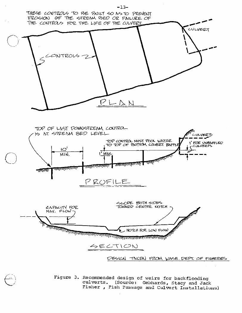
b. Construct weir(s) downstream to back water into
structure. This technique reduces velocity by
reducing slope. Figures 3 and 4 present approved
design for weir utilization.
c. Auxiliary culverts will decrease excessive velocities
("'
caused by development of a head upstream of the structure.
Auxiliary culverts should be designed to function only
when the primary facility is just under excessive
velocity limit.
C,, /'
~
d. Replace existing structure or change proposed structure
design to eliminate velocity problem.
Maximum velocities within a structure are normally encountered
at the downstream end. However, if the slope changes within the
structure, velocities can be highest within the structure. This
situation is most frequently encountered where the structure's slope
changes or where the structure is partially backflooded (Figure~.
The most frequent solution to the problems depicted in Figure 5
is replacement of the structure with one that satisfies passage
criteria. Other solutions should be coordinated with Department
engineers. (/:
()
0
f)
-13-
IH~~ t.OJJII2;0l..-? -ro 0e.. 00lt..T .-so !':.? 10 "Pe.E:.V~i E"eo~1o10 of=" ~ "":>-re-c~-.>t-A 9;>t:.O orz: rt>lt-UIZ.E- or= \)1e.. C.Ok)Tt20L.-? 'fZl!Z. \~C. 1.-!Fe OF The. CuL-V~ .........-... , r
\09 OY 1-h.SI QaW~?\12..\::.M-\. {..d.)\1201.-\.:? t>\ ~\\Z.e~t-A ~~o t-e-1/t::.\-
101
-ro? ~-nzoL MIY:>\ ?COL WI':.\'GIZ.. >0 \OP or e:aTTCJM. c..QI....\/eef 'Bh>l
P got=="\l-E-___ -
hi.-OPC- 13c=>nt ?1(/I::.<S "'TOA.II:.'\2.0 .:::..~t...'fT€12... tJOTC..H
~ e:. L.-\\ 0"-)
..,_..,.. ,..--,,......G.U L-VtSe...\
.,.,.. ----
--c.:;'-;!.~ \' rOle \J!V&FFi,EO
c.u(, 1/E:Oe.. T':::.
Qe:<S\~~ "'"'11->~E:tJ r~ \VI':.~. 0€-PT. OF FIS~E::lZlES
Figure 3. Recommended design of •veirs for backflooding culverts. (Source: Gebhards, Stacy and Jack Fisher , Fi::>h I' a::> :::sage anc.l Culvert In:::sta.llaLluus)
/11\ ll_, " I
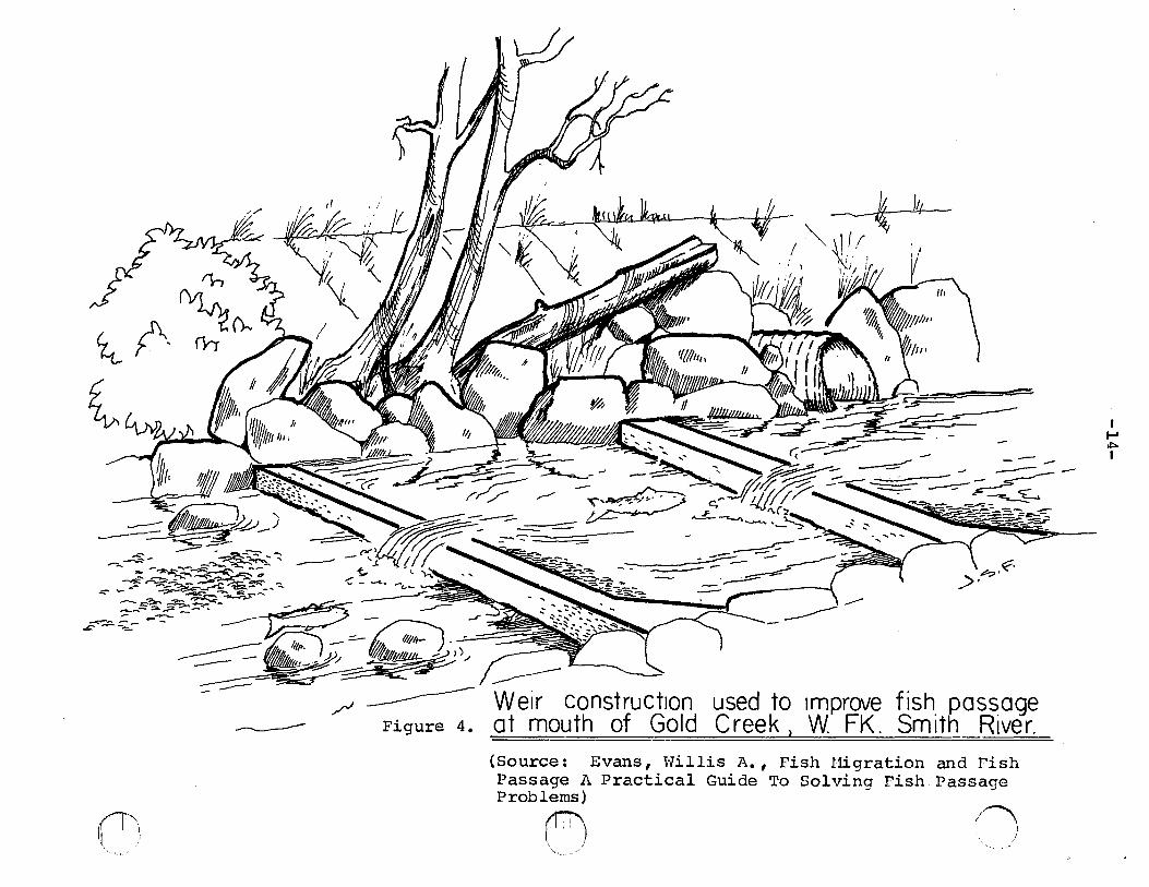
----- / -------------- Weir construct1on used to 1mprove fish. pas~age Figure 4. at mouth of Gold Creek ) W FK. Sm1th Rtver.
(Source: Evans, Willis A. , Fish Higration and Pish Passage A Practical Guide To Solving Fish Passage Problems)
0 :;) I
I 1-' ol:>o I
\/\: "'----)
0
()
-15-
------ ..... - ~...._ .......... _,_____ -......... ~-----~~//&# .......... - .......... ~ -- """ .... _________ _
---------- -/1 -------------- ----
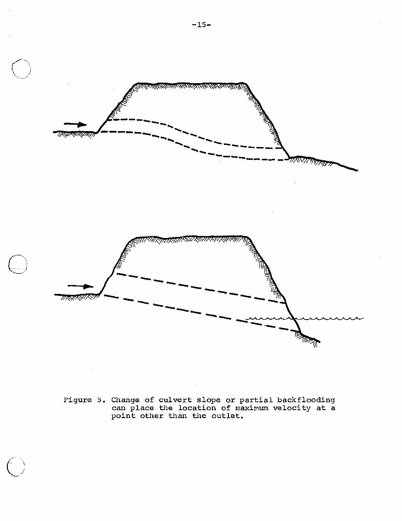
Figure 5. Change of culvert slope or partial backflooding can place the location of maximum velocity at a point other than the outlet.
-16-
Inadequate water depth
1. Problem. Fish require sufficient water depth to attain
maximum swimming abilities. The depth required is
directly related to fish size with larger fish requiring
deeper \'later. When insufficient depths are encountered,
fish are unable to produce full propulsion.
2. Causes of inadequate depth. The two most frequently
encountered reasons for insufficient water depth are
steep slope and a wide, flat channel bottom (no low
flow channel).
a. All other factors being constant, the steeper the
slope of a structure the shallower the \V'ater depth.
b. All other factors being constant, the wider the
structure bottom the shallo\r1er the \rTater depth.
3. Solutions to inadequate \vater depth problems.
a. Install properly designed baffles (Figure 2) to
concentrate lower flows into low 'l.·later channel
ti1ereby increasing water depth.
C',
- ~,:'
C~>
(- '
'--='
0
0
E)
b.
-17-
Construct weir{s) downstream of the structure to
back water into it {Figure 3). Weir height can be
adjusted to meet minimum depth standards.
c. Replace existing structure or modify proposed
design to eliminate depth problem.
Excessive entrance jump
1. Problem. Fish jumping ability can be exceeded, thus
blocking fish movement.
a.
b.
In general, adult trout can negotiate a vertical jump of
one foot. However, if a series of jumps is required, a
jump of one-half foot at each is preferred.
Salmon and steelhead can normally negotiate single jumps
of two to three feet vlithout excessive difficulty. How
ever, any series of individual jumps should not exceed
one foot.
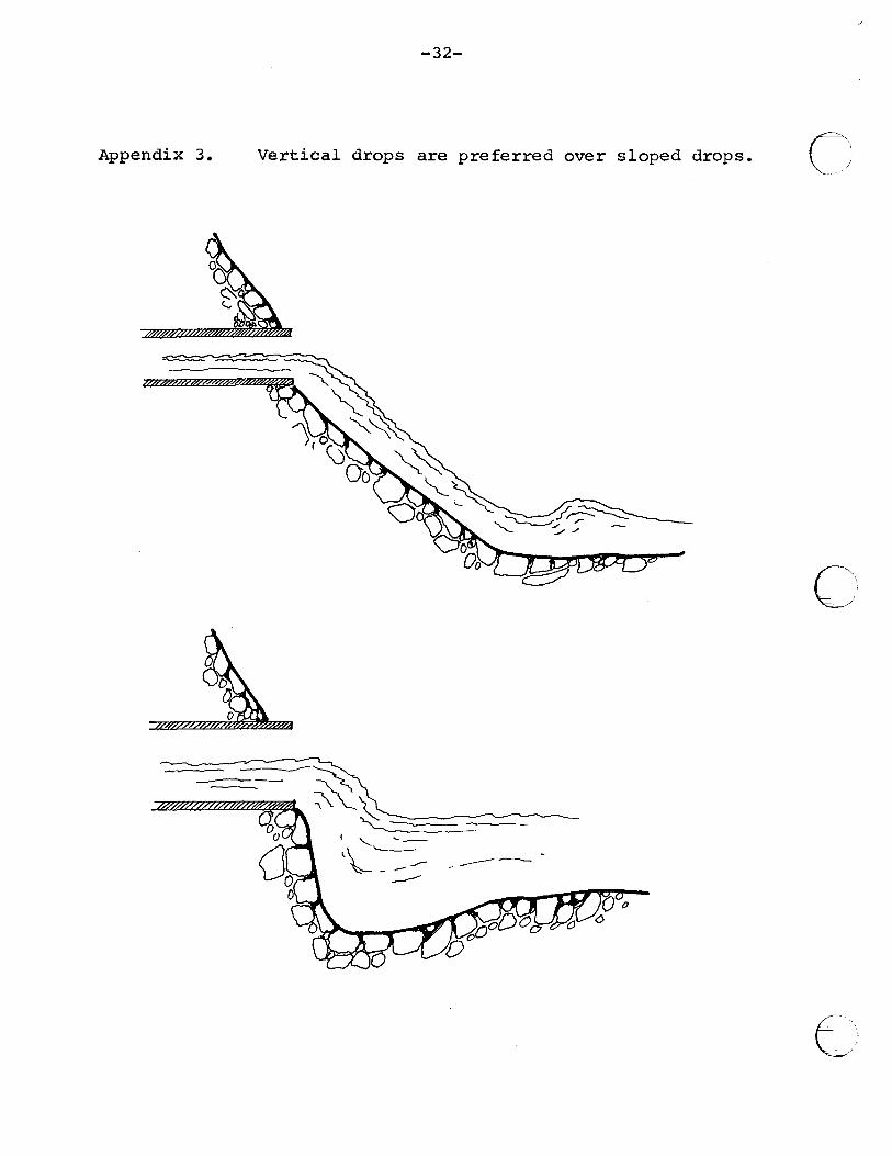
c. Any structure that will require a jump should be designed
with a vertical drop, not sloped (Appendix 3). Sloped
drops significantly increase fish passage problems.
d. Jumps near maximum ability of fish may necessitate
numerous jump attempts resulting in undue exertion
and possibly physical damage to fish.
-18-
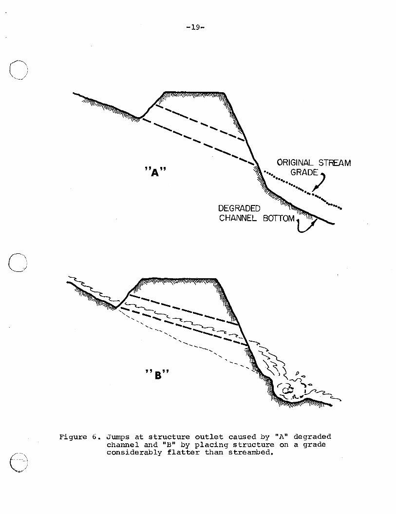
~. Causes of jump. The two basic causes for a jump at the
downstream end of a structure are bed scour and slope of C';
3.
structure placement (Figure 6).
a. Degradation of the streambed belm'l the structure can
result in lowering the water surface below the down-
stream end of the structure. This occurs most frequently
in steep gradient streams with erodible bottom materials.
Degradation of a receiving stream can create a jump at
a structure near the mouth of a tributary.
b. Placement of a flat sloped structure on a steep sloped
stream builds in a jump.
Solutions to excessive entrance jump.
a. Fish have difficulty in jumping when an adequate pool
is not available for them to gain required swimming
speed and vertical thrust. The following approximate
dimensions should be used to design a jump pool.
(1) Pool length should equal three times the maximum
width of the culvert or a minimum of ten feet.
(2) Pool width should equal two times the maximum
width of the culvert or a minimum of eight feet.
r-:\ ~/
c~'~
0
0
( -,\. - ,
-~/
-19-
.......... "- ...... ,,~....... ..... ..... "'!! . ........... ... ......... ............
.............. ...... ......
........... ..... ORIGINAL STREAM "A" • GRAD/E ••• ••• ~ ····· ~ ..... ....
DEGRADED
... ~~ ' .. CHANNEL BOTTOM v
...................... ~ ........ ...._ ........ -'---.......'---... ---....., ', ""'- ........ ......_ (..~~ ', ..................... ~-c::
............. ........ .............. ~-......... "" .... , ........... ',
.............. '---..... ..... , ......
....._ .....
"B"
. ....
Figure 6. Jumps at structure outlet caused by "A" degraded channel and "B" by placing structure on a grade considerably flatter than streambed.
-20-
(3) Depth should equal one and one-half to two times
the height of the jump required with a minimum
depth of two feet.
b. Utilization of weir(s) to backflood structure which
eliminates or reduces jump to acceptable height
(Figure 3).
c)
c. Replace existing structure or redesign proposed structure
to eliminate entrance jump problem.
d. Utilize a fish passage facility such as an Alaskan
steep pass, to provide entrance into structure.
Guidelines for Structures
Location
Structures should be located according to the following:
1. There should not be a sudden increase in velocity
iramediately above, belov;r, or at the crossing.
2. Structures should not be located on a sharp bend in the
stream channel.
3. Structures should be designed to fit the stream chru1nel
alignment. They should not necessitate a channel change
to fit a particular crossing design.
C~':
e--/ _;p
n '-.____/
0
C)
-21-
Type
When a new structure is to be installed, the Department of
Fish and Wildlife would recommend the following in order of
priority:
1. Bridge
2. Arch plate
3. Open bottom box culvert
4. Countersunk corrugated pipe
5. Countersunk box culvert or smooth pipe
6. Corrugated pipe with grade less than 0.5 percent
7.
a.
Concrete bottom or smooth pipe with grade less than 0.5 percent
Corrugated pipe with baffles on grade between 0.5 and 5 percent
9. Concrete bottom or smooth culverts with baffles on grade between 0.5 and 5 percent
10. Structure with fishway
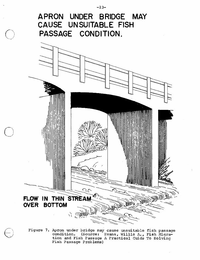
Bridges: Bridges are the preferred structural type as they
seldom cause fish passage problems and permit retention
of the natural streambed. Bridges with concrete aprons
cause problems by necessitating a jump and/or by causing
the water to spread out in a thin flow across a wide
apron (Figure 7).
Arch plate: This structure is desirable for fish passage as
it maintains a natural stream bottom. Most frequently
encountered problem is an inadequate foundation.
-22-
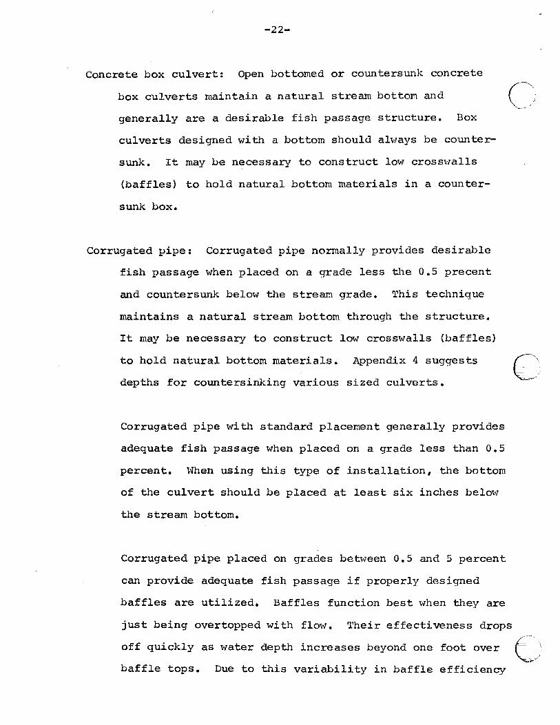
Concrete box culvert: Open bottomed or countersunk concrete
box culverts maintain a natural stream bottom and ~, generally are a desirable fish passage structure. Box
culverts designed with a bottom should ab1ays be counter-
sunk. It may be necessary to construct lo"' cross\valls
(baffles) to hold natural bottom materials in a counter-
sunk box.
Corrugated pipe: Corrugated pipe normally provides desirable
fish passage when placed on a grade less the 0.5 precent
and countersunk below the stream grade. This technique
maintains a natural stream bottom through the structure.
It may be necessarJ to construct low crosswalls (baffles)
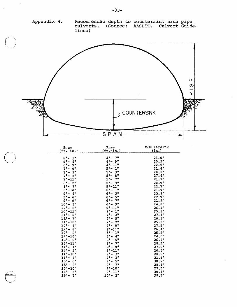
to hold natural bottom materials. Appendix 4 suggests
depths for countersinking various sized culverts.
Corrugated pipe with standard placement generally provides
adequate fish passage when placed on a grade less than 0.5
percent. ~vhen using this type of installation, the bottom
of the culvert should be placed at least six inches below
the stream bottom.
Corrugated pipe placed on grades bet\veen 0. 5 and 5 percent
can provide adequate fish passage if properly designed
baffles are utilized. Baffles function best when they are
just being overtopped with flow. Their effectiveness drops
(~'
off quickly as water depth increases beyond one foot over e-~/' -~
baffle tops. Due to this variability in baffle efficiency
0
0
8
-23-
APRON UNDER BRIDGE MAY CAUSE UNSUITABLE FISH PASSAGE CONDITION.
Ill:
lll!!l'llill'l' II
:l!\1 111:il il
I ~~~~.1, 11!
1
I
-------~ FLOW IN THIN OVER BOTTOM
\ \ \
Figure 7. Apron under bridge may cause unsuitable fish passage condition. (Source: Evans, Hillis A., Fish 11igration and Fish Passage A Practical Guide To Solving Fish Passage Problems)
-24-
and inherent debris problems, baffled structures are only
recommended at new crossings when a bridge or other more
desirable structure is not practical.
Smooth pipe: Due to their lower roughness factor, smooth pipes
have more problems meeting fish passage criteria than do
corrugated pipe. Otherwise, comments for corrugated pipe
apply.
Fishways: Structures incorporating fishways should be recommended
only if all other options are unsatisfactory. Designs for
such structures must be approved by Department of Fish and
Wildlife engineers.
Structure size
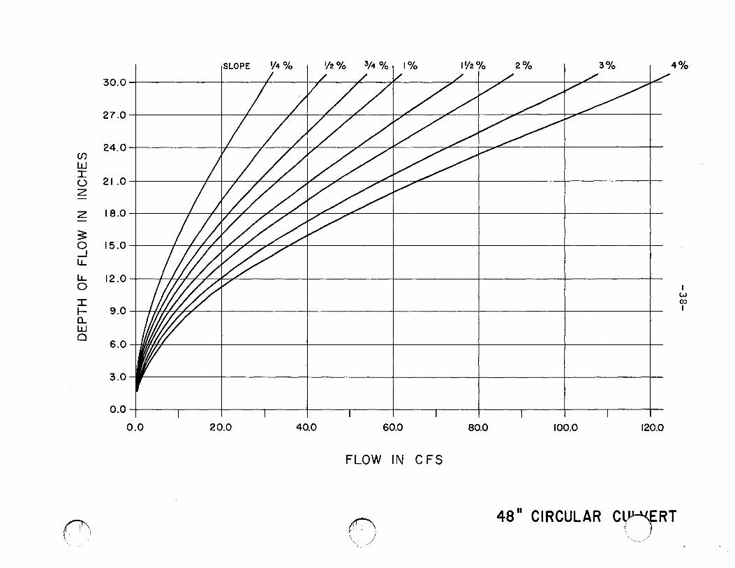
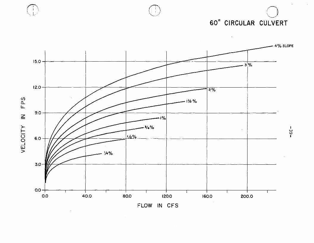
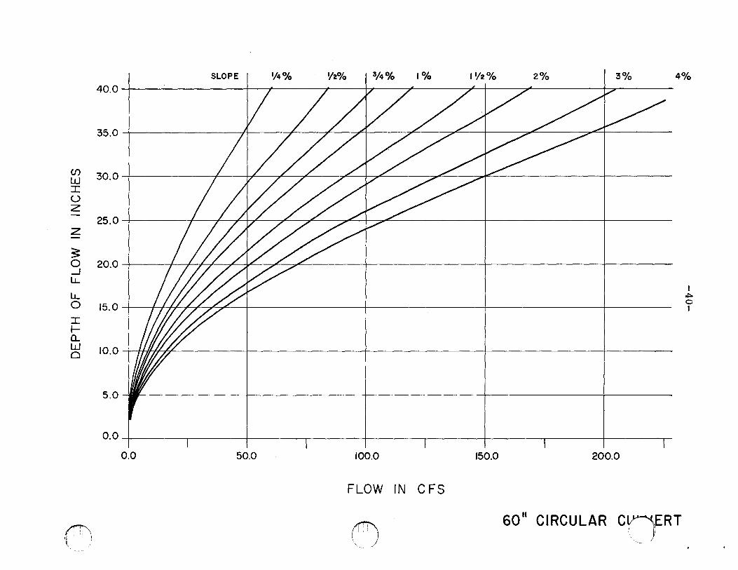
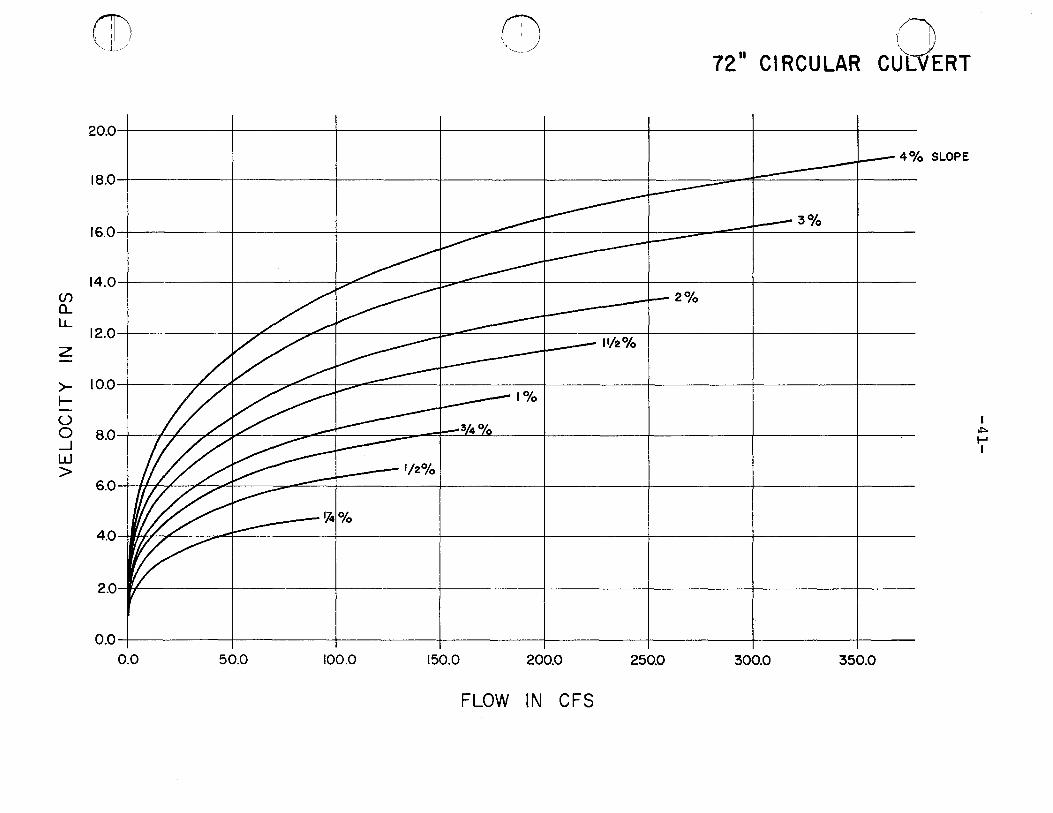
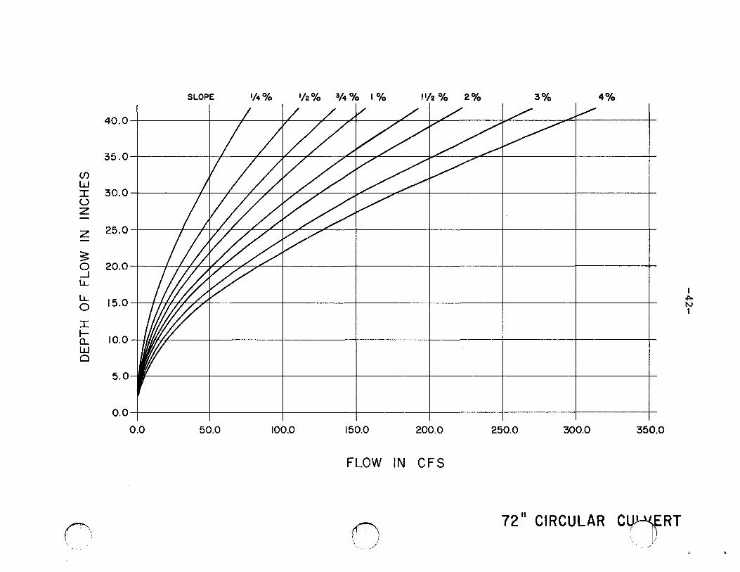
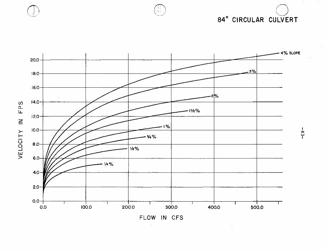
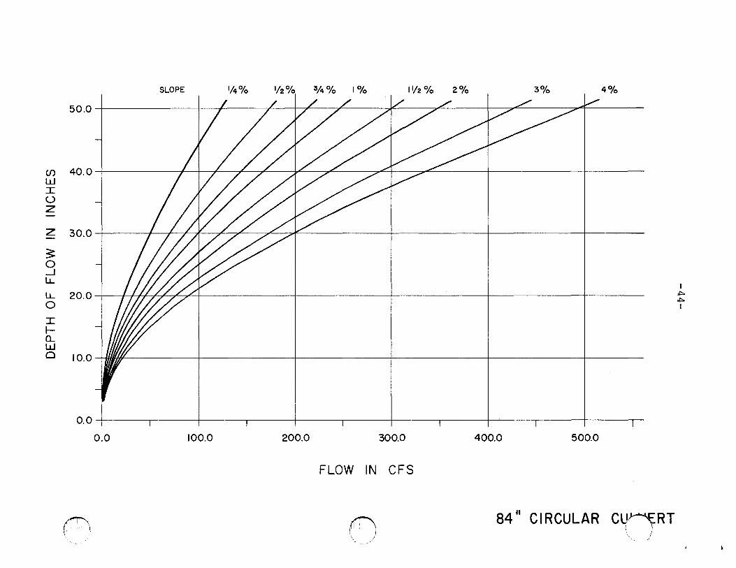
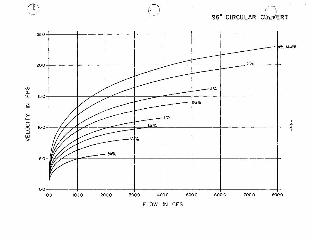
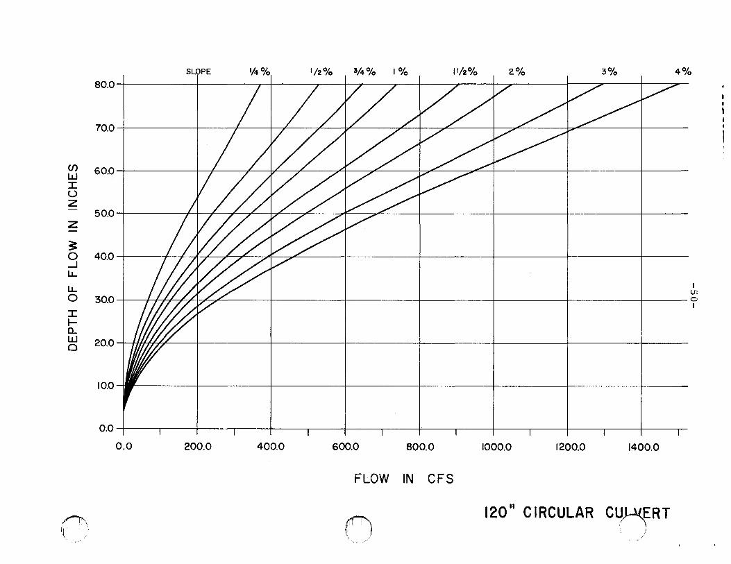
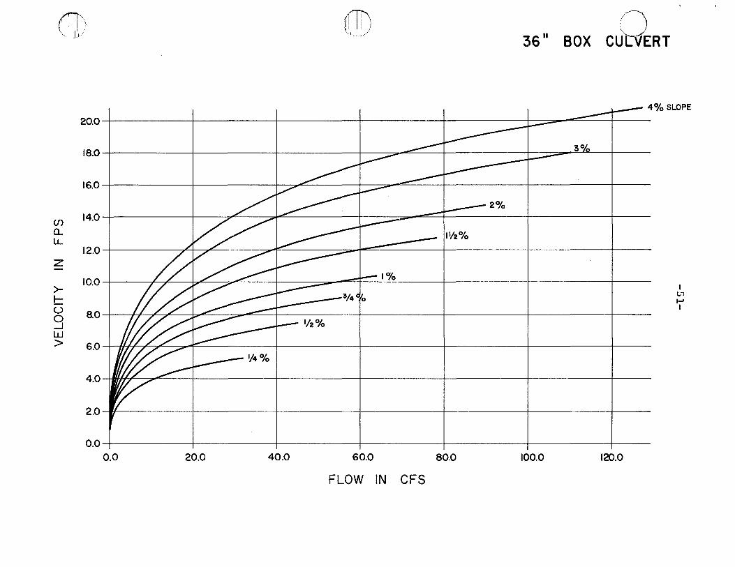
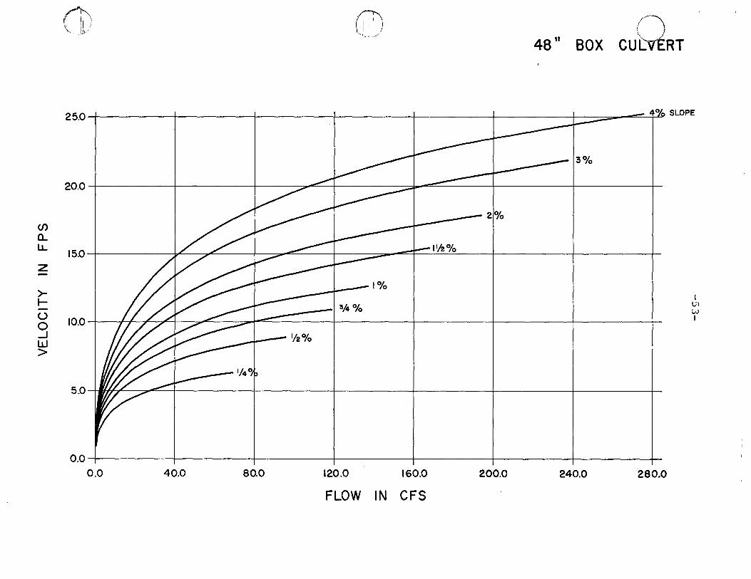
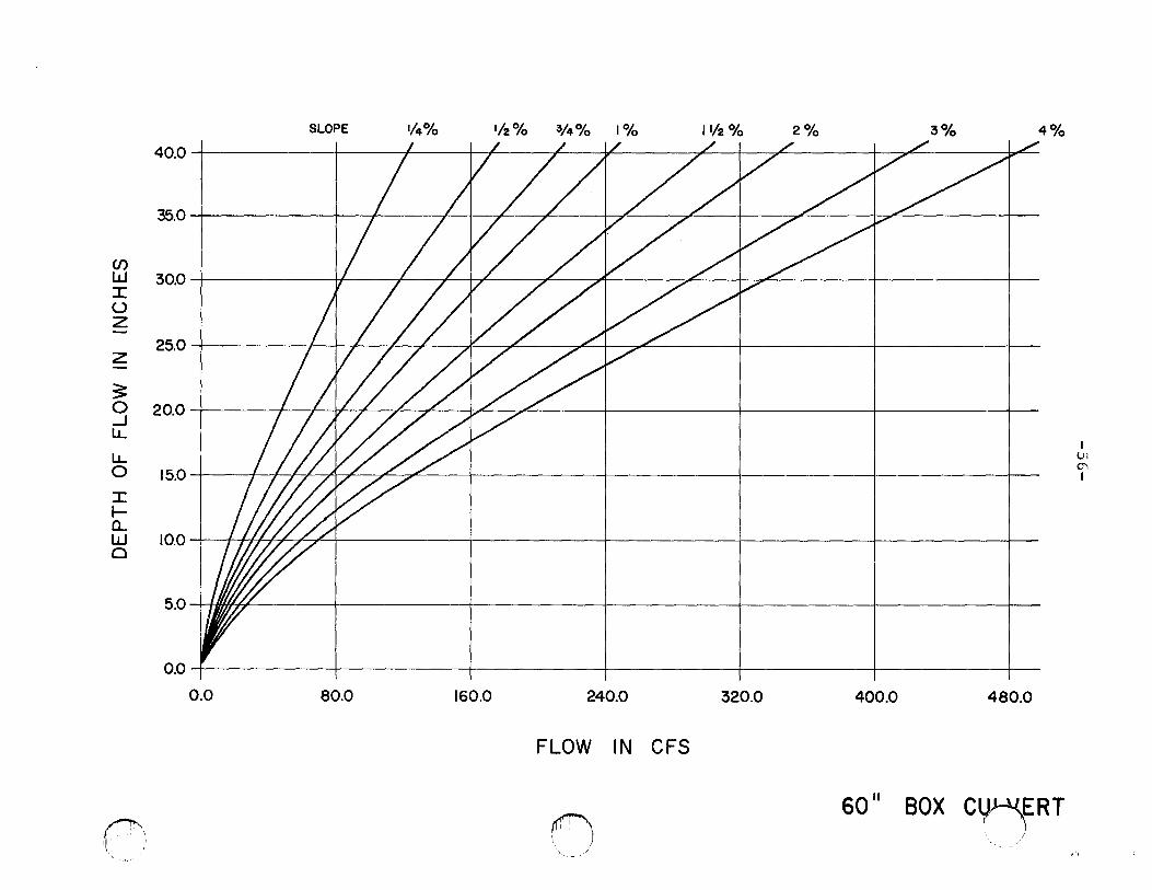
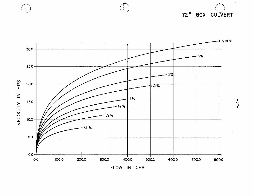
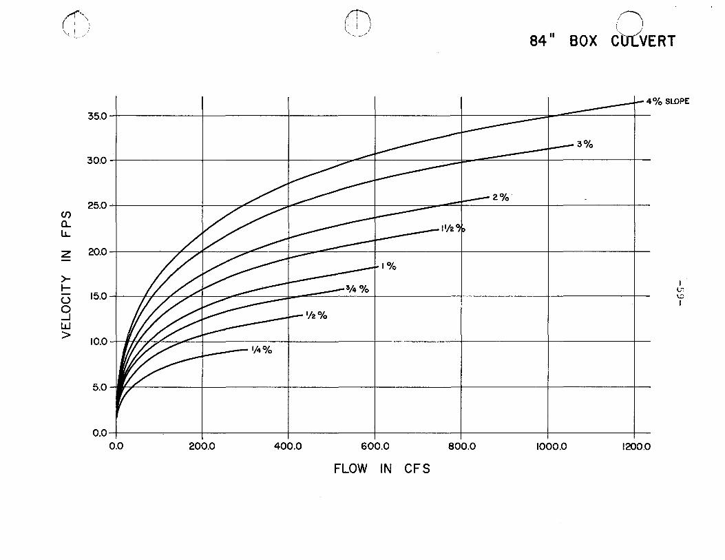
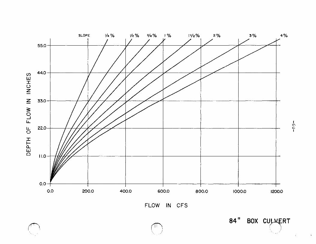
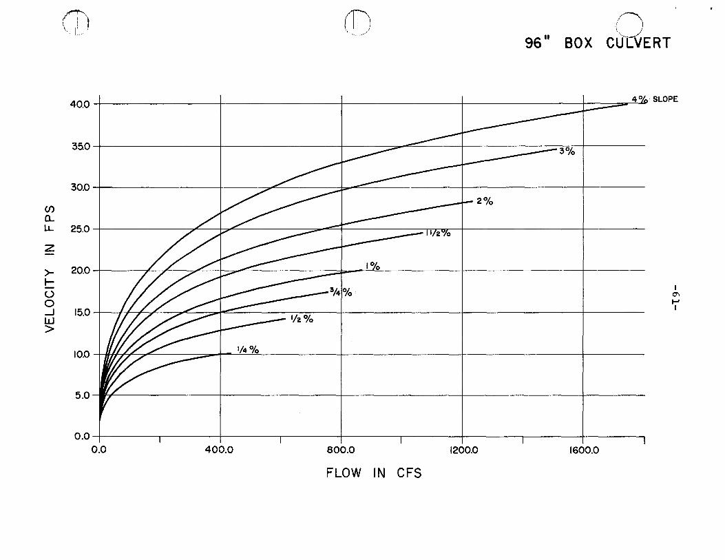
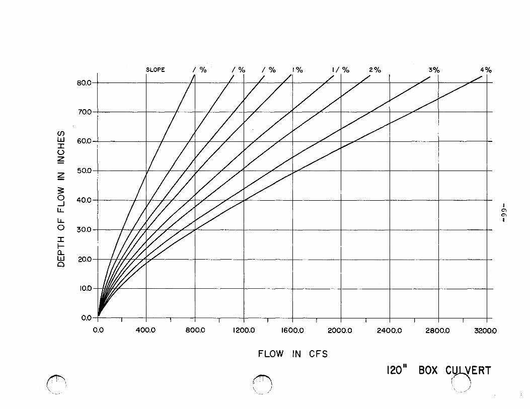
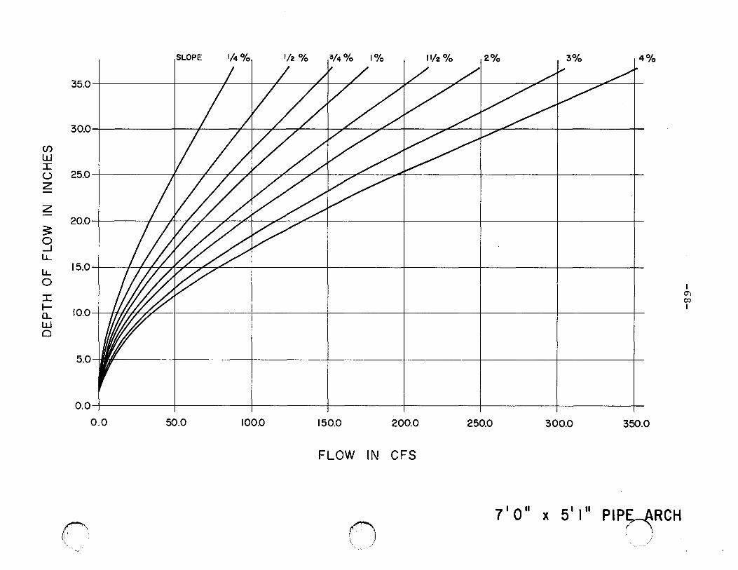
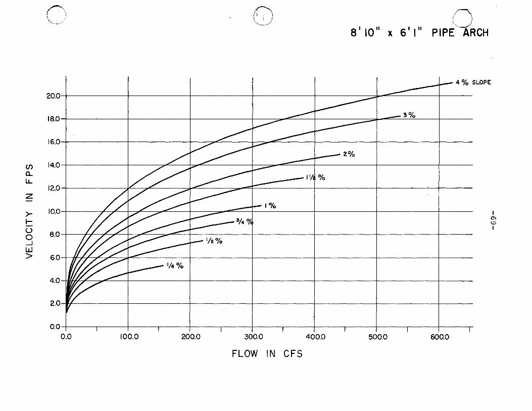
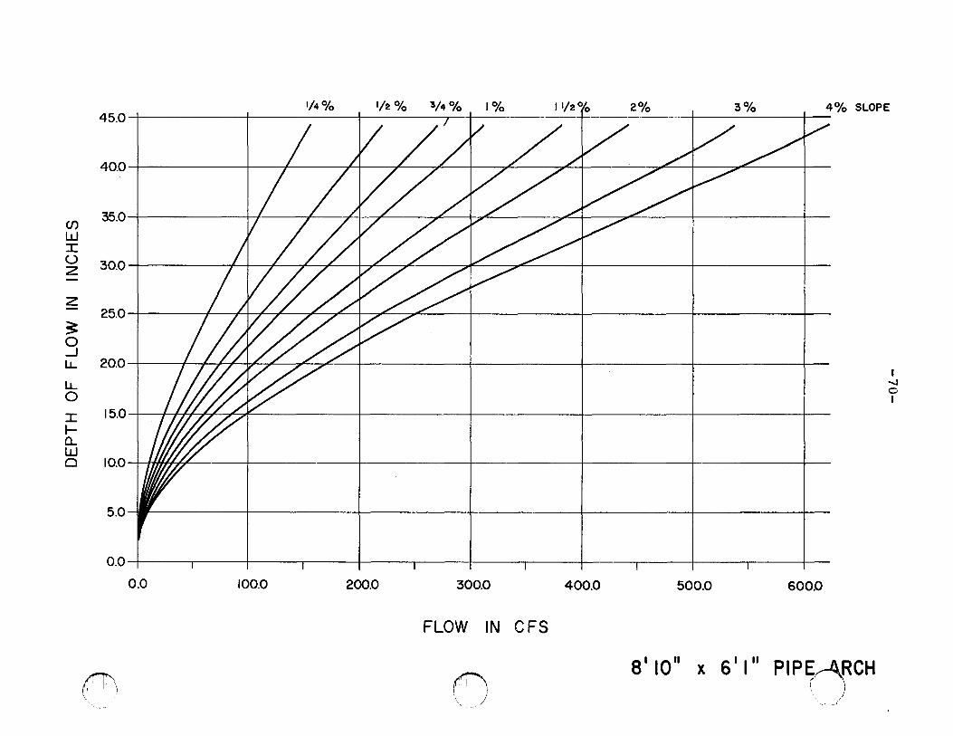
Data contained in Appendix 5 (performance curves for culverts)
are of extreme value in determining slope and size of culverts
required to satisfy departmental fish passage criteria.
In addition to fish passage, structure size should consider
the following points:
1. New structures should be designed to accommodate at
least the flood of 25 year occurrence. Crossings
with reduced capacity frequently wash out resulting
in substantial sedimentation and need for additional
construction.
c=:; "-.._--J
c~
€/
0
0
~)
2.
-25-
Structures shou~d be of adequate size to accommodate
anticipated floatable drift (wood, ice, etc.) and
allow for boat traffic where required.
3. Structures and associated approaches should not unduly
restrict floodway capacity. Restriction of the floo&vay
can result in structural failure, excessive flooding and
abnormally high velocities leading to bed scour down
stream of structure.
4. Structure size should be sufficient to prevent formation
of a head upstream of structure.
Miscellaneous
1. Research has not ind~cated that lighting of long culverts
is necessary to achieve adequate fish passage.
2. Multiple barreled culvert installations are not generally
desirable. A larger single pipe will normally have lower
velocities and will be less apt to plug with debris.
3. When two or more culverts are available, fish will generally
try to enter the one with higher velocities.
4. When two or more culverts are available with equal velocities,
fish will genera~ly attempt to pass the wider one.
-26-
REFERENCES
Alaska Department of Fish and Game and u. s. Forest Service, Logging and Fish Habitat. 22 pp.
Alaska Department of Fish and Game. Swimming Capability of Migrating Salmon in Freshwater.
AASHTO. 1975. Task Force on Hydrology and Hydraulics, Memo.
Bainbridge, R. 1960. Speed and Stamina in Three Fish. Journal of Experimental Bio. 37:129-153.
Bell, Milo c. 1973. Fisheries Handbook of Engineering Requirements and Biological Criteria. u. s. Army Engineer Division, North Pacific Corps of Engineers, Portland, Oregon.
Blaxter, J. H. s. and w. Dickson. 1959. Observation on the Swimming Speeds of Fish. Scottish Home Department.
Bureau of Commercial Fisheries. May 1964. Progress Report No. 106.
------------------· June 1964. Progress Report No. 107.
-------------------· November 1964. Progress Report No. 112.
-------------------· June 1967. Progress Report No. 142.
--------------· January-March 1969. Progress Report No. 154.
--------------· Research on Fishway Problems.
Clay, c. H. 1961. Design of Fishways and Other Fish Facilities. Queen's Printer, Ottawa, Canada 1-301.
Dellisle, G. E. 1962. Water Velocities Tolerated by Spawning Kokanee Salmon. California Fish and Game Department. Vol. 48, No. 1, pg. 77-78.
Evans, Willis A. 1974. Fish Migration and Fish Passage a Practical Guide to Solving Fish Passage Problems. u. s. Department of Agriculture, u. s. Forest Service, RegionS 43 pg.
Fish Commission of Oregon. September 4, 1969. Some Effect of Delay on Migrating Adult Salmonids. Water Resources Division.
Gauley, J. R. 1967. Effect of Water Velocity on Passage of Salmonids in a Transportation Channel. Fish and Wildlife Service, Fish. Bull. 66:59-63.
c:~
{\~ ~·
~' '-~---~/
0
0
£\ ~'
-27-
Gauley, J. R. - c. s. Thompson. 1963. Further Studies on Fishway Slope and Its Effect on Rate of Passage of Salmonids. u. s. Department of Interior, Fish and Wildlife Service, Fish. Bull. Vol. 63, No. 1, pg. 45-62. '
Gebhards and Fisher. Fish Passage and Culvert Installations. Idaho Fish and Game Department.
Huston, J. 1966. Fish Passage Through Culverts. Montana Fish and Game Department. Memo. 1 pg.
Idaho, State of. Statement of Policy Concerning Facilities at Culvert Installations.
Kay, A. R. and R. B. Lewis. June 1970. Passage of Anadromous Fish Through Highway Drainage Structures. California Division of Highways, Research Report 629110.
King, Horace Williams. 1954. Handbook of Hydraulics, FourthEtlition, McGraw-Hill Book Company, Inc., New York.
Koski and Saltzman. Fish Passage Through Culverts. Oregon Game Conunission.
McClellan, Thomas. Fish Passage Through Highway Culverts. Federal Highway Administration.
Metsker. Fish versus Culverts. u. s. Forest Service - Region 4.
Miller, J. M. 1972. Guidelines for Protection of the Fish Resource Resulting from Highway Construction and Operation. Fisheries Research Board, Winnipeg.
Oregon State Highway Division. 1974. Hydraulics Manual, Salem, Oregon.
Oregon, State of. Oregon Revised Statutes. Legislative Counsel Committee, Salem, Oregon.
Oregon Wildlife Commission. 1973. Oregon Wildlife Code. Portland, Oregon. 126 pp.
Otis, M. B. 1964. Suggested Measures for Minimizing Damage1D Fishing Streams from Highway Projects. New York State, Department of Environmental Conservation. 4 pp.
Prett, J. R. August 1965. Swimming Energetics of Salmon. Scientific American, Vol. 213, No. 2. 6 pg.
Reimers, N. Trout Stamina. Progressive Fish Culturist, 18:112.
Shoemaker, R. H., Jr. Hydraulics of Box Culverts with Fish Ladder Baffles, osc.
-28-
Slatick, E. Pipe.
Passage of Adult Salmon and Trout Through an Incline Trans. American Fisheries Society 100(3): 448-455.
• Passage of Adult Salmon and Trout Through Pipes. ----~u~.~s-. Fish and Wildlife Service. Special Scientific Report
C-592, 18 PP•
u. s. Government. 1975. Logging Road and Protection of Water Quality. u. s. Environmental Protection Agency, Region X, Seattle, Washington. 313 pp.
Washington Department of Fisheries. Regulations and Recommendations for Fish Passage, Facilities at Culvert Installations.
Weaver, c. R. 1963. Influence of Water Velocity Upon Orientation and Performance of Adult Migrating Salmonids. USDI and F&WS Fishery Bulletin Vol. 63, No. 1. 97-122 pp.
Webster, D. A. 1965. Leaping Rainbow of the Finger Lakes. New York State Conservation Department. Information Leaflet.
c\
(--
' =~
(') _____ _/
C) -
t)
-29-
Appendix 1. Oregon Revised Statutes 498.268 and 509.605
ORS 498.268
498.268 Fishway required for artificial obstruction across body of water. (1) Except as otherwise provided by law, no person shall construct, operate or maintain any dam or artificial obstruction across any body of water in this state in which game fish exist unless he provides a fishway in such location and of such design as the commission determines will provide adequate upstream and downstream passage for fish at the dam or obstruction.
(2) If the commission determines that a fishway required by subsection (1) of this section does not provide adequate passage for fish, the commission shall so notify the person who constructed or who operates or maintains the dam or obstruction. The notice shall also specify the manner in which the fishway is inadequate, and shall require the person who constructed or who operates or maintains the dam or obstruction to make appropriate alterations, specifying a reasonable time for the completion thereof.
(3) A person required to alter a fishway pursuant to subsection (2) of this section may file with the State Water Resources Board a protest against the alteration requirements on the grounds that such alterations are not in the public interest. A person who protests pursuant to this subsection must file the protest with the board not later than the lOth day after the date of the notice of alteration requirements from the commission.
(4) Within a reasonable time after receiving a protest, the State Hater Resources Board shall give notice to the protestant and the commission and hold a hearing to determine whether the fishway alterations are in the public interest. In making the determination, the board shall approve, disapprove or approve with modifications the fishway alterations required by the commission. In making the determination, the board shall consider the state water resources policy and the considerations set forth in ORS 536.310.
(5) If the person required by this section to make alterations to a fishway fails to make the alterations in the manner and within the time required by the commission or the State Water Resources Board, as the case may be, the commission may remove the dam or obstruction, or any parts thereof.
-30-
Appendix 1. (continued)
(6) No person who has constructed or who oper-ates or maintains a dam or artificial obstruction for which a fishway is required by this section shall fail to keep the fishway free from obstruction to the passage of fish. However, no prosecution for violation of this subsection shall be commenced unless the violation continues after the commission has given wri-ten notice of the violation to the person who is to be prosecuted. Every day of violation of this subsection after the date written notice was given to the person to be prosecuted constitutes a separate offense.
ORS 509.605
509.605 Fishways required over artificial obstructions, approval by director; failure to complete fishway. (1) Except as otherwise provided in ORS 498.268 or 509.640 or 509.645 or the state water resources policy formulated under ORS 536.300 to 536.350, it is unlawful for any person, municipal corporation, political subdivision or governmental agency to construct or maintain any dam or artificial obstruction across any stream in this state frequented by anadromous or food fish without providing a passageway for such fish over the dam or artificial obstruction as near the main channel as practicable.
(2) The director shall examine, from time to time, all dams and artificial obstructions in all waters of this state frequented by anadromous or food fish. If in his opinion there is not a free passage for such fish over any dam or artificial obstruction, and except as otherwise provided in ORS 509.640, the director may notify the owner or occupant thereof to provide free passage within a reasonable time with a durable and efficient fishway, of such form and capacity and in such location as shall be determined by the director. Except as otherwise provided in ORS 509.645, no owner or occupant of such dam or artificial obstruction shall fail to complete such fishway to the satisfaction of the director within the time specified.
(3) Any person, municipal corporation, political subdivision or governmental agency shall, prior to construction of any dam or artificial obstruction in any waters of this state, obtain a determination from the director as to the need or lack of need for passage of anadromous or food fish. If the director determines that a fish passage facility is needed, approval of the proposed plans and specifications for such facility must be obtained from the director prior to construction of the dam or artificial obstruction.
c,
C) '
(~,'
C) /
t-
]a_ C' ~ _j 1--
C', 0
~
0
>-<..? 0::: w z w
Appendix 2.
30
25
20
15
10
5
-31-
Salmon energy efficiency curve. (Source: Prett, J. R. , The Swimming Energetics of Salmon)
0 ~----_.------~------~------._ ______ ._ ____ __ 2 3 4 5
WATER VELOCITY (fps}
()
-Z£-
(~-) .. '--- _____ /
0
e~ -
-33-
Appendix 4. Recommended depth to countersink arch pipe culverts. (Source: AASHTO. Culvert Guidelines)
SPAN
Span Rise (ft.-in.) (ft.-in.)
6 ·- 1" 4'- 7" 6 1
- 4" 4'- 9" 6'- 9" 4'-11 n
7'- 0" 5'- 1" 7'- 3" 5'- 3" 7'- 8" 5'- 5" 7'-11" s•- 7" 8'- 2" 5'- 9" a•- 7" 5'-11" 8'-10" 6'- 1" 9 ·- 4" 6'- 3" 9'- 6" 6 ·- 5" 9'- 9" 6'- 7"
10'- 3 11 6 1- 9"
10'- 8" 6'-11" 10 1 -11 II 7'- 1" 11 1
- 5" 7'- 3" 11 1
- 7" 7'- 5" 11'-10" 7'- 7" 12 1
- 4" 7'- 9" 12 1
- 6" 7'-11" 12'- 8" a•- 1" 12'-10" 8'- 4" 13 1
- 5" a•- 5" 13'-11" 8'- 7" 14'- 1" 8 1
- 9" 14 I- 3" 8'-11" 14 1 -10" 9 1
- 1" 15 1
- 4" 9 1- 3"
15 1- 6" 9'- 5"
15 1- 8" 9'- 7"
15 1 -10" 9 1 -10" 16 1
- 5" 9'-11" 16 1
- 7" 10'- 1"
COUNTERSINK
Countersink (in.)
21.0" 20.5" 22.0 11
21.4" 20.8" 27.4" 21.7" 20.9" 22.7" 21.9" 23.8" 22.9 n
21.9" 24.0" 26.1" 25.1" 27.4" 26.3" 25.2" 27.5" 26.4" 25.2" 24.0" 26.4 11
28.9" 27.6 11
26.3" 28.9" 31.6" 30.2" 28.8" 27.5" 30 .1" 28.7"
w (/)
0::
-34-
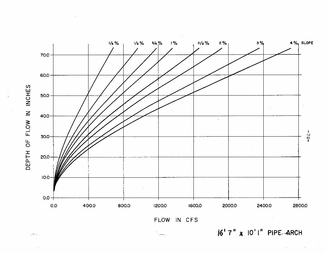
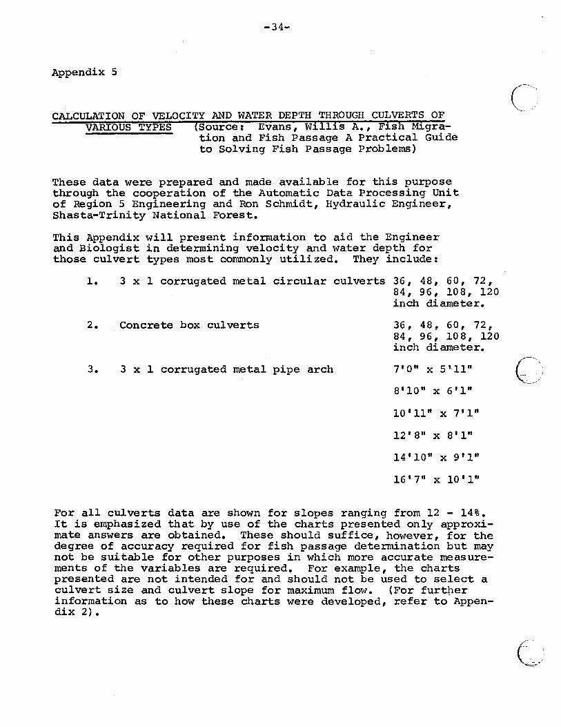
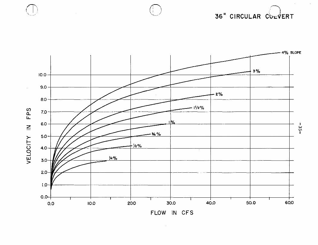
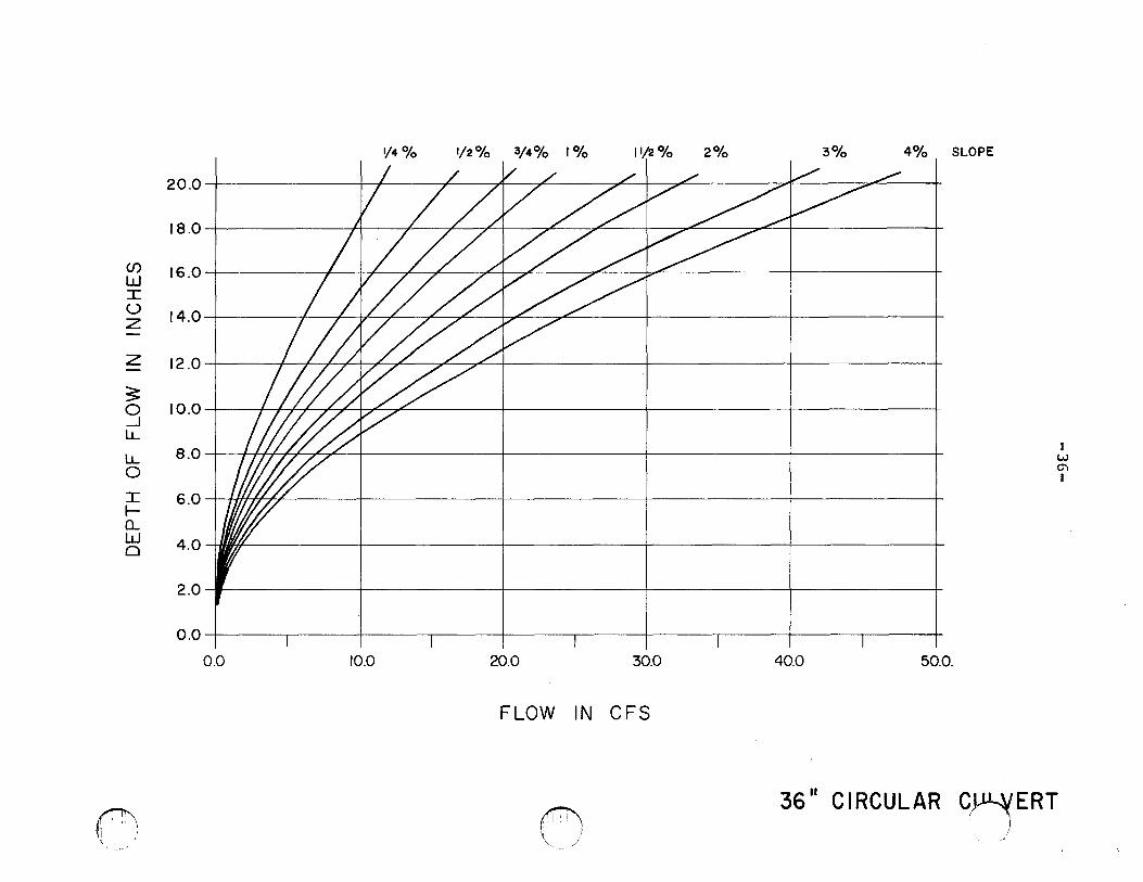
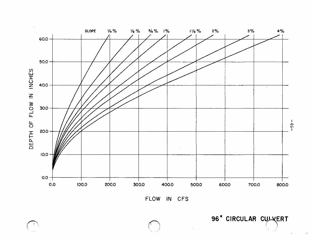
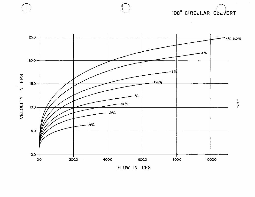
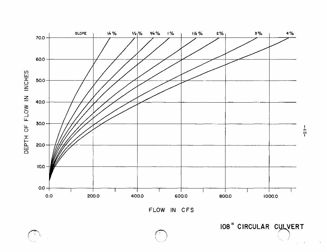
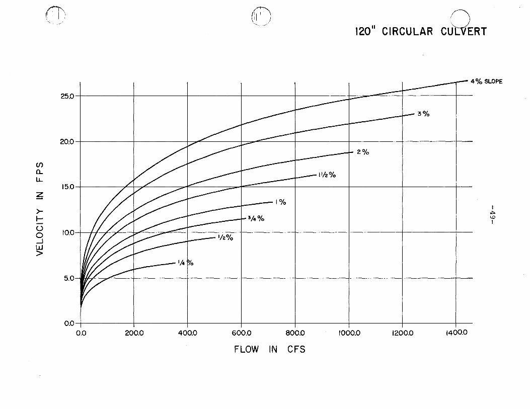
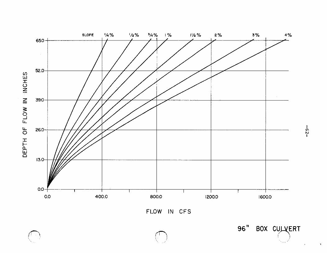
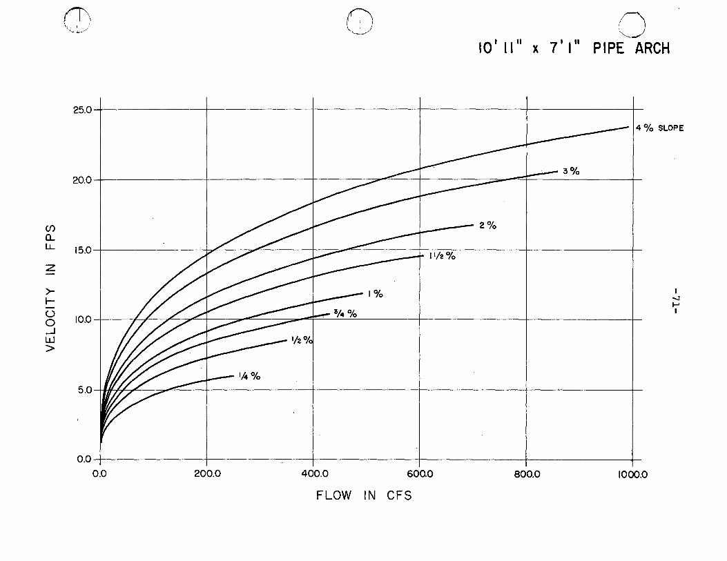
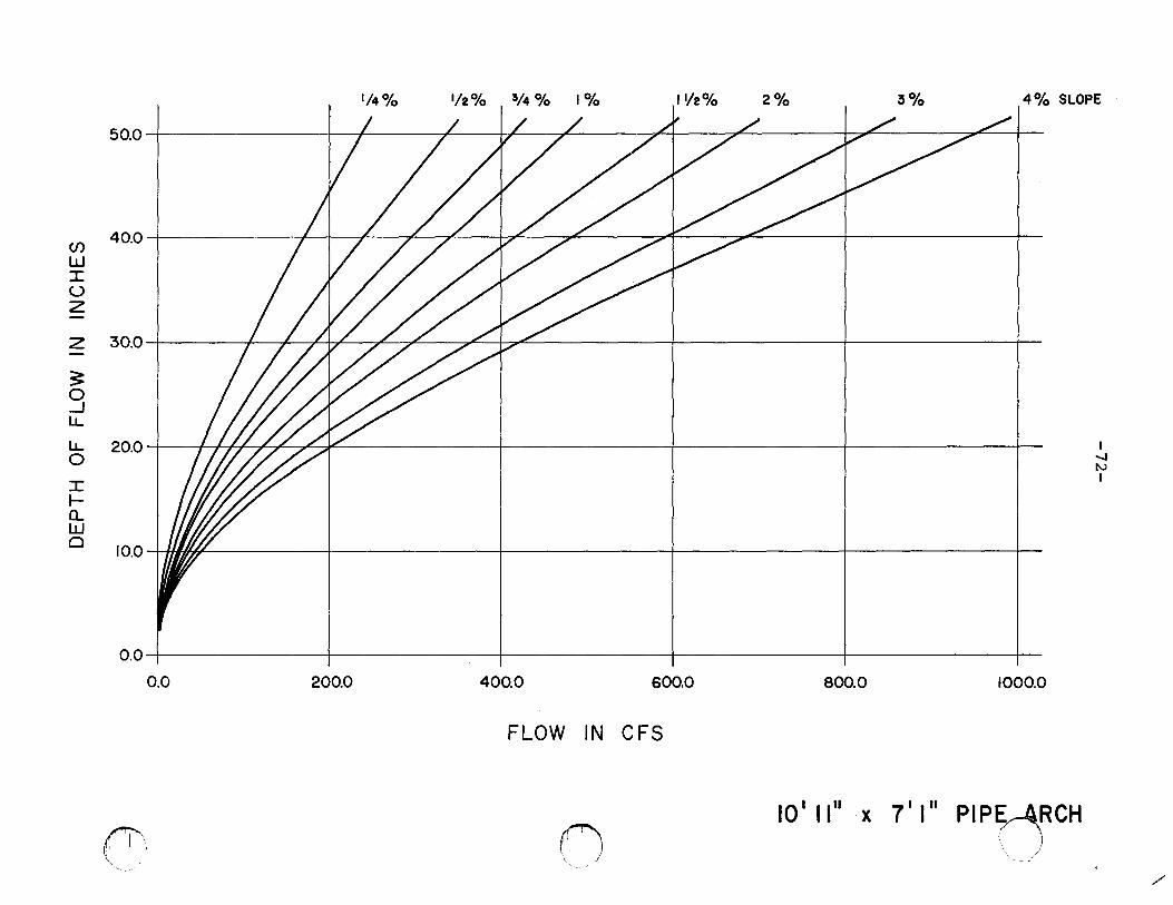
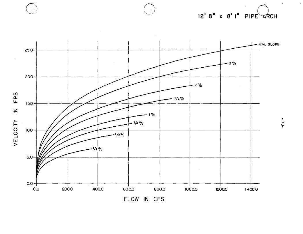
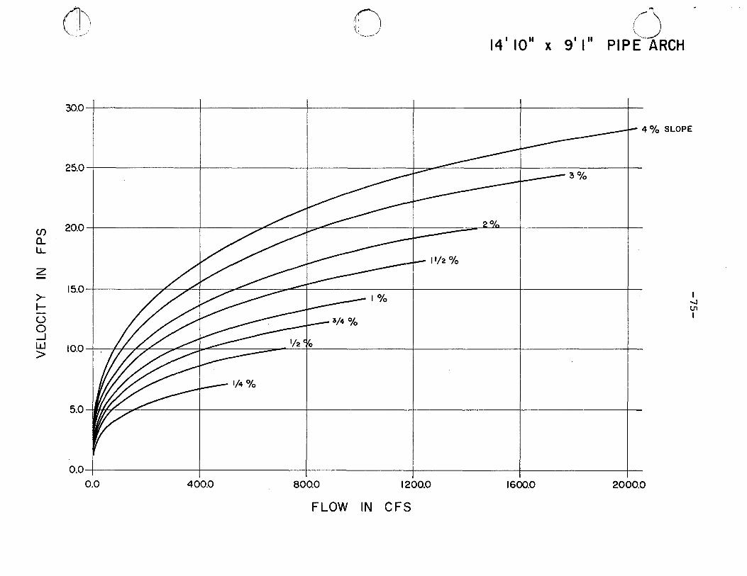
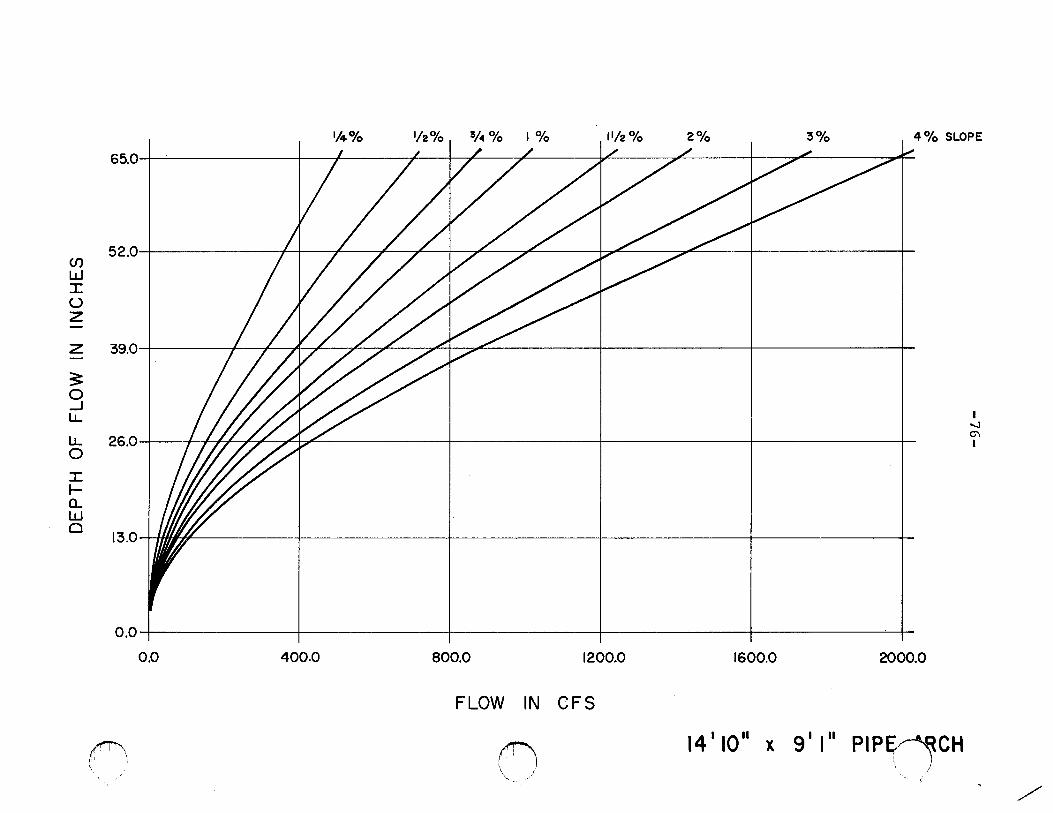
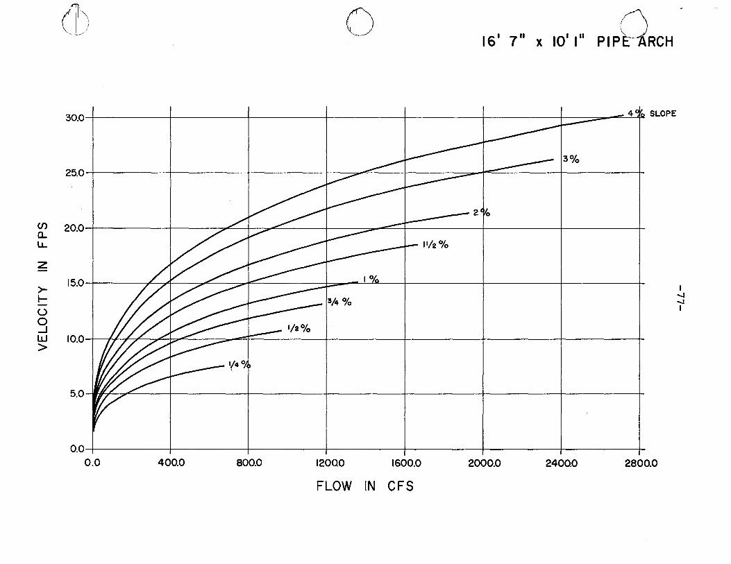
Appendix 5
CALCULATION OF VELOCITY AND WATER DEPTH THROUGH CULVERTS OF VARIOUS TYPES (Source: Evans, Willis A., Fish Migra
tion and Fish Passage A Practical Guide to Solving Fish Passage Problems)
These data were prepared and made available for this purpose through the cooperation of the Automatic Data Processing Unit of Region 5 Engineering and Ron Schmidt, Hydraulic Engineer, Shasta-Trinity National Forest.
This Appendix will present information to aid the Engineer and Biologist in determining velocity and water depth for those culvert types most commonly utilized. They include:
1. 3 x 1 corrugated metal circular culverts 36, 48, 60, 72, 84, 96, 108, 120 inch diameter.
2. Concrete box culverts
3. 3 x 1 corrugated metal pipe arch
36, 48, 60, 72, 84, 96, 108, 120 inch diameter.
7 1 0 11 X 5 1 11"
8 1 10 11 X 6 1 1 11
10 1 11 11 X 7 1 1 11
12'8" X 8 1 1 11
14 1 10 11 X 9 1 1 11
16 I 7 11 X 10 I 1 11
For all culverts data are shown for slopes ranging from 12 - 14%. It is emphasized that by use of the charts presented only approximate answers are obtained. These should suffice, however, for the degree of accuracy required for fish passage determination but may not be suitable for other purposes in which more accurate measurements of the variables are required. For example, the charts presented are not intended for and should not be used to select a culvert size and culvert slope for maximum flow. (For furt~er information as to how these charts were developed, refer to Appendix 2).
c~~
(~,
e-~-~ ~
~01') ~ li / '-'· _,,_./'
CJ)
a.. l1...
z -
>-I--(.)
g w >
10.0
9.0
8.0
7.0
6.0
5.0
4.0
3.0
2.0
1.0
0.
0
0.0 10.0 20.0 30.0
FLOW IN CFS
36" CIRCULAR cc::JERT
40.0 50.0
---4% SLOPE
60.0
I w U1 I
U)
w I u z -z -
3: 0 _j
LL
LL 0
I I-(L w 0
.('i1\ ~~ . :
' '
I 20.0
18.0
16.0
14.0
12.0
10.0
so 1
6.0
4.0
2.0
0.0 I
0.0
1/4% 1/2% I I /
~I
I I
10.0
3/4% 1% 11/2% 2% 3% 4% SLOPE I/ / ... I
I I I I I w C"' I
i I I I I
20.0 30.0 40.0 50.0.
FLOW IN CFS
() I
\ "~-·- /
36 II CIRCULAR C()ERT
(f)
a.. l.J...
z ->-t--(.)
0 _J
w >
1~, l 11
)
~., ,c . ..-/ f) l
. 0 48 11 CIRCULAR CULVERT
15~~----------+-----------~--------~r---------~-----------+-----------r---------j- 4% SLOPE
3% 12.o-L----+------f--~~4----=i:::;::;;;;;;---~==--~-----r--
9.0
6.0 I IL %1 I I I I
w .._J
I
3.0 ~~~~--+----+----+----~----~
o.o~----------+-----------~--------~r---------~-----------+-----------r---
0.0 20.0 40.0 60.0 80.0 100.0 120.0
FLOW IN CFS
LOPE '/4% I '12% 3/4% I 1% IY2% 2% I 3% I 4% I I I
30.0
27.0
24.0 (f)
w I
21.0 (_)
z -z 18.0 -~ 0 15.0 .....J IJ..
LL. 12.0 0
9.0 I /lff#i I I I I I I w
I 00
I- I
a.. w a
6.0
3.0
0.0 I I I I I I I
0.0 20.0 40.0 60.0 80.0 100.0 120.0
FLOW IN CFS
~~ \ A
48" CIRCULAR cr;rRr "~~._" /
m ' 1/· f) .
~- 0 60
11 CIRCULAR CULVERT
4% SLOPE
15.0~------------+------------+------------~--~=--=~----~-----------+---------
12.0
(f)
a.. LL.
9.0 z
>- 11/4Q/o
I I I I
r- w - "" u I
0 _J w >
3.0
o.o~----~----~------~----4-----~-----+------~----+-----~-----+----~---
0.0 40.0 80.0 120.0 160.0 200.0
FLOW IN CFS
en w :r: ()
z -z -~ 0 .....J LL
LL 0
:r: I-0.... w 0
~\ r '! , Ill I
\
SLOPE 1/4% V2% 3/4% 1% jlf2% 2% 3% 4% 40.0~--------------~~~----~~---n~--~------~-r----~---------+~-------
35.0~--------------~-----T----~--~r-----~--~~--~--~~------~~---------
30.0
25.0
20.0
I
I
I ~
I 0 hW~ I 15.0 I
10.0
5.0
o.oL--.-----+--~-~+--r---t------r--1--T 0.0 50.0 100.0 150.0 200.0
FLOW IN C FS
f) 6011
CIRCULAR CV~ERT ' /
(]) 0 --
72" CIRCULAR CQERT
20D~--------~---------+---------+--------~--------~~--------~--------+-----
4% SLOPE
18.0T---~---r----+---+----+---=:=::;:;:----~::::::::::::c~
16.0
14.0 (/) CL LL
12.0 z ->- 10.0 r--(.)
8.0 1 Jh~~ 1-3/4% I I I I I
0 ~
_j 1-' I w
> 6.0
4.0
2.0 F/ I
l_---~----+--~-----+----4---~---~~ 0.0 0.0 50.0 100.0 150.0 200.0 250.0 300.0 350.0
FLOW IN CFS
SLOPE 1/4% '12% 3/4% lo/o 1'/2% 2% 3% 4% I I I I/ / v /I / I ./"'" v
40.0
35.0
(f)
w ::r: 30.0 (_)
z -z 25.0 -~ 0 20.0 _J lL
15.0 IIIIU( I I I I I I I
lL .~=>-
0 N I
::r: I-
10.0 a... w 0
5.0
0.0 I I I I I I I I
0.0 50.0 100.0 150.0 200.0 250.0 300.0 350.0
FLOW IN CFS
n \ ~
'- ..-/'
72 II CIRCULAR cnRT
"'T1
r 0 :E
z ()
"'T1
(f)
VE
LO
CIT
Y
IN
FP
S
0 N
N
~
m
())
0 1
\)
~
m
(X)
0 0
b b
b b
0 b
b 0
0 b
0 b 8~----~---+-4r-+4~~~-4~~~~~~----~---+----+-
o N
0 0 0 (>I
0 0 b ~
0 p~----~---+----4----4----~--~~--~~--+-~~---++--
0 (J'I 8~----~---+----1----1----~--~~--~----+---~~--+4-
0
-£v-
~
~
0 (/) 5 "'0
1'11
('")
::::0
('")
c:
r )>
::::
0
('")
r9
I -
-
~
--
c: ~
----
~u
::::0 -i
!)
-- ,':3 co ~ =
("")
- ::
0 ("
")
c r )>
::0
("")
--
C
'----~
::0 -I
, r 0 ~
z () , (f
)
0 0 0 0 0 "' 0 0 0 (JJ 0 p 0 ~
0 p 0 (J1
0 0 0
DE
PT
H
OF
FLO
W
IN
INC
HE
S
"' O
J ~
(J1
p p
0 0
0 0
0 0
0 0
0 0
~
~
0
-vv-
CD n \('"-._, _____ .)
() 96" CIRCULAR CUL:'V'ERT
25.0~--------+---------~-------+--------~--------+-------~---------T--------,-
4% SLOPE
20.0 I I I I :b-__......-= · I I - "Ita I
(f)
a.. lJ_ 15.0
z ->-1-
10.0 1 I/~_A~4% I I -
I I I I
(.) ,::,.
0 l.TI
_J I
w >
.,~,_ ::::;;» I I I 50 Ill'/, ""' 1,.......... I I I I
0.04---------+-------~---------+--------4---------+--------1---------+--------~
0.0 100.0 200.0 300.0 400.0 500.0 600.0 700.0 800.0
FLOW IN CFS
SLOPE 1/4% 1/2% 3/4% 1% 1112% 2% 3% 4%
60.0-r--------r-------~-----T--+-~--~~----~~~~~----r---~~-+---=~--+--
50.0
CJ)
w I u z 40.0 -z
3: 0 30.0 _J LL
LL Iff~ 0
I 20.0
I .1::>-(j',
I
1-a... w 0
10.0
o.o~--------r--------+--------+-------~--------~--------~-------+--------+-
0.0 100.0 200.0 300.0 400.0 500.0 600.0 700.0 800.0
FLOW IN CFS
~\ n ', _____ /
96 II CIRCULAR C~ERT
"'T1
r 0 :E
z
VE
LO
CIT
Y
IN
FP
S
1\)
1
\)
(JI
6 (1
1 0
!J1
0 0
0 0
0 0
b p 0 ~ sj_--------+-----~~~~--~-ir---~--~--------r-
0 00
0 0 0 0 0 p 0
~
~
0 (/) 5
-Lf?
-, 1'
1
8
0 0) =
("")
:::tJ
("")
c r l>
::
0
("")
[~
fT1
::0 -i
, r /3
0
-
~
z () , U
>
0 co =
(')
- :::0
(')
c r )>
:::
0
-~
(')
'~~ rr
l :::
0 -I
0 0 1\)
0 0 p 0
DE
PT
H
OF
FLO
W
IN
INC
HE
S
1\)
p 0
~
p 0
(11 p 0
en
0 0
.....,
0 0
(J) 5 "'0
1'11
g -+-------r------~----~~~~~~~~~~--~~------~-
0 ~
~
0 0 ~
0 0 ~ .,. ~
0 ~
0 en
0 p 0
- j\l::
~
0 1\)
(X)
~
0 0
0 0
CJI
~
0
0 0 0 0
~
~
0
-av-
1(1\ ,, '
(') '
I ., ,._ ... .--"
120" CIRCULAR C~QERT
4% SLOPE
25D~---------+--------_,-----------r---------~--------~~---=--~----------r--
20.0
(/) (L
lL. 15.0
z 1%
>-I
ol:>o
~ 1.0
- I ()
10.0 0 _.J w >
5.0
0.0~---------r---------r---------+---------+---------+--------~--------_, __ _ 0.0 200.0 400.0 600.0 800.0 1000.0 1200.0 1400.0
FLOW IN CFS
(f)
w :c (.)
z
z -3: 0 ...J u... u... 0
:c ~ a.. w 0
~I I~'
4% 80.0~---------+--------~------~--~~--~--4---~~---r~-------+--~~----r---=--
70.0~---------r----r----r~--~~~~----~-+--~-----+~~----~~------_, ____ __
60.0
50.0
40.0
I I
I
I U1
I 0
I I I 30.0 I ///~ 20.0
10.0
o.o~---,r----r----.----r----.----r----.----+----.----+----.----4----.---~----~
0.0 200.0 400.0 600.0 800.0 1000.0 1200.0 1400.0
FLOW IN CFS
!1fT!\ \. }
\ ~/
120" CIRCULAR C~~ERT J
11
r 0 :E
z ()
"T1
(/)
VEL
OC
ITY
IN
F
PS
1\)
0
1\)
~
(1)
~
0 1
\)
~
(1)
())
p b
b b
b 0
b b
b b
b 0
p 0 1\)
0 4-----~---4~--~-4-4~~~--~~~--+---~----~----+--
b ~ 04-----~---4----~--+-++~.,~~~----~--~----~----+--
b (1)
0 b ()) g ~,_ _
_ ,_
__
~--~--~---r---r---r---r---r---++
b
-TS
-
,-_
__
3 \---
---
=
CD
0 X

,~) (J
.I
0')
=
a:J
0 X
("')
,J
,,_
fTI
;:o
-I
11
I 0 ~
z ()
11
en
0 0 1\)
p 0 .p
. g m
0 b CX>
0 b 0 0 b 1\)
0 0
0 0 (J
'I 0
DE
PT
H
OF
FLO
W
IN
INC
HE
S
p 0
-zs-
(J1
0
1\)
g 1
\)
(J'I b
~
~
0 ~
~
0 ~ "" ~ 0 ~
0 s 1\)
~
0 N
~
0 01
~
0 ~
~
0 en
r 0 , ITI
(/)
CL
(il'\ "J: I .. :
l ..,.!"'
If;\ \ I , )
\"-l._ . ._. ____ /,
48 II ()
BOX CUi:vtRT
25D-r--------~----------r---------,_---------+----------r---------~--==---=~
20.0,_---------+----------r-----~=-~--------~~~----~----------+----------+-
I.L. 15.0 z
~ IOJ ;/~ 13/4% I I I I ..J w >
5.0 11/H/ _,.,- I I I I I I I
~---~------~---~~--~------~---~~~~ 0.0 0.0 40.0 80.0 120.0 160.0 200.0 240.0 280.0
FLOW IN CFS
I lJl w I

r~)
!"
-
t
-_
/
DE
PT
H
OF
FLO
W
IN
INC
HE
S
p N
N
()
I
0 (J
I (J
I g
(J1
0
b b
0 b
b 0
0 b

(f) a.. LL.
z ->-I--(.)
0 ...J w >
G) r1fi\ t,l ! )
'(·l~·-··-·- 0 BOX CULVERT 60"
30.0 4% SLOPE
25.0 - , ...
20.0
15.0 I ;/~
1"/o
I I I
I l!l lr. I
10.0
5.0 I.V/ ~ I I I
OD-r----------~----------+-----------r---------~-----------+----------~---
0.0 80.0 160.0 240.0 320.0 400.0 480.0
FLOW IN CFS
SLOPE 1/4% 1/z% 3/4% 1% 11/2% 2% 3% 4% 40.0 I I I I / / V / I / I / :V'"
35.0
(/) w 30.0 I (.)
z -25.0 z -
~ 0 20.0 _J lL
I I
I I Vl
I C\ ,If/~~ I 15.0 I lL 0
I ~ Q.. w 10.0 0
5.0
0.0~----------+-----------~--------~-----------+----------~----------~--
0.0 80.0 160.0 240.0 320.0 400.0 480.0
FLOW IN CFS
('i'\ 'II_
(i) 60 11
BOX CY)ERT !·,
11
r 0 =E
z ()
11
(f
)
VE
LO
CIT
Y
IN
FP
S
1\)
1
\)
01
0 (}
I p
(}I
p (}
I p
0 0
0 0
0 0
0 0 0 0 o~-------+~~~~~~~~~~~--~-------+------~---
0 1\)
8-r-
----
-_,-
---~
--*-
~~--
~--~
---T
--~-
-_,-
----
---r
--0 01
0 p 0 ~
0 p 0 (}I
0 p 0 0')
0 p 0 -...1
0 0 0 00
0 p 0
-LS
-
;:9
G
_., N =
aJ
0 X
("')
~0
~
~
0 en
,., r
::::0
0 --
i , JT
I

~3 =
a
J
0 X
("")
\,]
:::0
--t
., r 0 ·:E
z () ., c.n
0 0 0 0 0 I\)
0 0 0 01
0 0 0 ~
0 0 0 U'l
0 0 0 en
0 0 0 .......
0 0 0 (X)
0 0 0
0 0 0 0
DE
PT
H
OF
F
LO
W
IN
01 g
-8S
-
INC
HE
S ~
0 0
(JI g
(f'\ '
\. !. y (D ·~ ... /
BOX d0vERT 84 11
4% SLDPE
35.0-r--------r----+----+----+------=~..........,::::::::::::::::::::=_J__
300~----------~-----------+------~~~--------~~=---~------+-----------,_-
25.0. (/)
a.. Ll..
z 20.0 ->-
15.0 1
1- 1/~~ ---S/4% I - I I u I I
0
l.r: \!)
I
_J w > 10.0
5.0~~--------~----------4-----------+-----------+-----------+-----------+--
0.0~----------+---------~~---------+----------~----------~----------r-
0.0 200.0 400.0 600.0 800.0 1000.0 1200.0
FLOW IN CFS
SLOPE 1/4% 1/2% 3/4% I% 11/2% 2% 3% 4%
55.0-r-----------r----~----~~--~~~~----~~----~--------~~------~~~
CJ) 44.0 w :c (.)
z -z 33.0 -~ 0 _J
lL
22.0 1 1/#U~ I I I I I
lL 0"\
0 c I
I f-a... w a 11.0
0.0
0.0 200.0 400.0 600.0 800.0 1000.0 1200.0
FLOW IN CFS
~) 84 11 BOX CU~RT 01
' I / ', ,,
z (")
"'T1
(/)
VE
LO
CIT
Y
IN
FP
S
0 (J
I g
1\)
1
\)
01
01
~
(JI
g (J
I g
fJ1
p 0
0 b
0 0
0 0 0 ~
0 o-r------r-----~--~~~+-~~~--~r-~---r------r------+-
0 (J) 8~------~----~----~~~~~--~--H-----~---+--~-----+-
0
-T9
-
(/) 5 "0
1'11
<.0 en <
)
=
CD
0 X
:~3
=
CD
0 X
(j
'~
::0
--
i
., 5 :E
z () ., U>
0 0 ~
0 0
DE
PT
H
OF
FLO
W
IN
INC
HE
S
1\)
en
0
m
fJ1
0
g ~----------~----~~~~~~~~~~--~~-+------~~~ en
5 , 111
0 ~
';fl
;;;-.. ~
0
())
~
~
0 ~
g 0 ~
0 s:::
1\)
~
0
1\)
0 p
I\)
0 ~
0
II
r 0 :E
z ()
II
(f)
VE
LO
CIT
Y
IN
FP
S
N
1\)
O
J O
J ~
0 (J
l 0
!J1
0 (J
l 0
g 0
0 0
0 0
b b
0 0
0 0 (X) S-r-----+------~----~~~~--1--+~--~~~--+-----~-
o N
0 p 0 ~ 0 b 1\)
0 0 0 0 1
\)
~
0 0 0
-£9
-
l/0
',~
(3
0 (X) =
CD
0 X
(')
~)
~
~
0 ~
en
IT1
r 0 :::
0 ,
--t
1'11
c~) 0 (X
) =
CD
0 X
('")
,j
:::0
-I
., 5 ~ z () ., (/
)
0 b ~
0 p 0 (X)
0 0 b 1\)
0 0 b en
0 0 b 1\)
0 0 g ~
0 0 b
0 b
DE
PT
H
OF
F
LOW
IN
IN
CH
ES
1\)
g 01
p 0
-v9-
~
p 0
(J1
g en
p 0
"f. ~
0 ~
~
0 ~ .,. ~
0 ~
0 ~ ~
0 1\)
~
0 01 ~
0 ~ ~
0
(}) L {:) ~,'"'--"·u-
120 II 0
CULVERT BOX
~---- 4% SLOPE 45.0~--------~--------+--------+-------_,---------r--------r---~=-~=-------;-
40D-r--------r--------+--------~------~~~~--~--------+-~=---~~------~
35.0
(f) 30.0 a.. IJ..
z 25.0
I I
C\
I U1 I I I >-
20.0 1 t-()
0 _J
w 15.0 >
10.0
5.0
0.0~--------r--------+--------+-------~--------~--------~-------+--------+-
0.0 400.0 800.0 1200.0 1600.0 2000.0 2400.0 2800.0 3200.0
FLOW IN CFS
SLOPE 1% 1% 1% 1% 1/% 2% 3% 4%
80.0 I I /1 / I / / I / I / I 7.r I 7*' I
70.0
(J) w :I:
60.0
(..)
z
z 50.0
3: 0 40.0 .....J
I /!V/~/1 I I I I I I
l.J._ 0'1 0\
l.J._ I
0 30.0 :I: 1-CL w 20.0 a
10.0
on~--~----r---~---+--~----+---~--~----~--~--~----~--~--~--~----~
0.0 400.0 800.0 1200.0 1600.0 2000.0 2400.0 2800.0 3200;0
FLOW IN CFS
~i \ . ' ~ ' ....
P) '"- __ ,J
120" BOX CRERT \' _/

r:~ \ ,I /, "'--'·l·i>__.. 0 I '-....
7 1 0 11 X 5 1 111 PIPQRCH
20.0,_---------r---------+--------~----------~--------+---------,_--------~-
18.0 I i __..........,. 4% SLOPE
16.0 ~
i4.0 CJ)
a... lL 12.0
z I I /~ ---r- J.__ll/2%
>- 10.0
I-
8.0 I ~~-==::t::: 1%
I I I I I -
(.) C"\
0 -...J
_J I
w >
6.0 I~- I ---·t.%
1 ••••• - ~ - 1/4 f/o 4.0
2.0
0.0,_--______ ,_ ________ ,r--------,r--------,r--------~--------~--------~-
0.0 50.0 100.0 150.0 200.0 250.0 300.0 350.0
FLOW IN CFS
SLOPE 1/4% 1/z% 3/4% 1% 11/2% 2% 3% 4°/o
35.0 I I I I / / I / .V 7, I >..c I ~" I
30.0
en w I (.) 25.0 z
z 20.0
~ 0 _J
LL
LL 15.0
0
10.0 I jfffg I I I I I I
I
I 0'1 ro
I- I a.. w 0
5.0
L_--~--+---+---+---+-~~~~ 0.0
0.0 50.0 100.0 150.0 200.0 250.0 300.0 350.0
FLOW IN CFS
!("'\ 'l. ()
7' 0" X 5'1" PIPHRCH
,_ ... _./ .
11
r 0 :E
z ()
11
U
>
VE
LO
CIT
Y
IN
FP
S
p ~
(X)
~
(X)
1\)
1
\)
en
p 1
\)
en
p 0
b b
0 b
0 b
b b
0 0
0 0 0 p~----+----+-+--;-~~~~~~--~----r----+----,_----r----
0 ~
p-r----+---~----~--+-++~-+~~~--~+-~-+----,_----r---
0 01
0 p 0 ~
0 p 0
(=-~
,\
--j
----__,
......, 0
-
45.0 --·-----·---+_:_ _____ _
40.0 I I I /I / / I / / I 7, I 7',.,c I
(f) 35.0
w :c (.)
30.0 z -z
25.0 3: 0 _j
LL. 20.0
Iff~ I
LL. -...!
0 0 I
:c 15.0 1-a.. w 0 10.0
5.0
0.0
0.0 100.0 200.0 300.0 400.0 500.0 600.0
FLOW IN CFS
(!'\ f) a' 10" x 6' I" PIPY)RCH
\.,, -~ - / 'v-- _.J
11
r 0 ~
z ()
11
(J
)
VE
LO
CIT
Y
IN
FP
S
0 N
N
U
1 0
CJI
0 U
1 0
0 b
b 0
0 0 0 N
0-r----------~r-~~~~~~--~~~-----------+---------~--
0 0
-:::e
0
~
0 0 0
-:::e
0
en
0 p 0 - $ -:::e
0
-:::e
0
())
0 p 0 0 8 -!:>
0
-:::e
0 (/) 5
-TL
-"'0
FT
I
8 (3
0
=
>C
-.1 =
, , rr
1 , ____
________
l>u
::0
(')
:I
:
DE
PT
H
OF
FLO
W
IN
INC
HE
S
,')
1\)
()
I ~
(.11
0 0
g 0
p p
0 0
0 0
0 0 0
~
~
~
0
0
"TI
p ~
0 r
• 0
~
:E
0
;3
z ~
0
()
"TI
U>
en
0 p 0 "" 1'
0 ~
0 1\)
0 ~
0
-(X
)
-8
-)(
0
_...,
01
~
0
=
-o
-o
J 0 0 p
~
0 ~
:::0
0
0 en
::t
: r 0 ,.,
-'lL
-1'1
1
\
VE
LO
CIT
Y
IN
FP
S
0 (J
I 1
\)
1\)
~
p (J
I p
()1
0 0
0 b
0 0
0 0 '· .
. _
_/
11
en
0
r 0
0 b
~
z (~
) ('
")
())
11
0 0
(/)
0 0 0 p 0
1'\)
-(X
) =
i\5
0 )C
g (X
) - =
~
-o
8 -o
0
b ~
~
0 (/) r
0 0
:J:
""0
111
-£L
-

3 1'\
)
co =
)C
co - =
-o
-o
~J
::0
("
) :X
"'Tl
r 0 :E
z ()
"'Tl
(f)
0 b ~
0 p 0 en
0 p 0 Q)
0 p 0 0 0 p 0 ~
p 0 ~
0 p 0
0 0 p 0
DE
PT
H
OF
F
LOW
IN
IN
CH
ES
"' g
-vL
-
Uol
p 0
en g
(.11 g
~
~
0 (I) r 0 ., ITI
VE
LO
CIT
Y
IN
FP
S
o-
(.11
0 g
1\)
~ (~
!J1
!J1
0 0
0 0
0 \
_ _
_/ J
0 0 (X)
0 ,
p 0 r 0 :E
z ( 3
() , U>
1\)
0 p 0
~ -
0) §
0 =
)C
c.o =
1\)
-o
0
-0
""0
p rrlf-~\
0 ~
l>u
~
0 en
:::0
r ("
) 0
:I:
"'0
-SL
-1'1
1
a>
0 "'T
1 0
r 0
0 :E
':3
z ()
"'T1
(/)
1\)
0 p 0
~
0 m
=
0 0
)I(
0
<D =
""'0
""'0
~
j 0 p
-· 0
(")
:I:
\
0 0
DE
PT
H
OF
FLO
W
IN
INC
HE
S
01
0
1\)
en
0 -9
L-
U1
1\)
0
~ ~
0 ~
A ~
0 ~
0 ~ ~
0 N
~
0 01
~
0 ~
~
0 {/)
5 ., PI
, r 0 ~
z () , en
VE
LO
CIT
Y
IN
F P
S
1\)
0 0 g 1\)
~
0 g 1\)
0
) 0 p 0
-LL
-
0
en
....., =
)(
0
=
""tJ - ""tJ v
en
::::0
r (')
0 ""
0 :I
: 1'1
1