Safety The Army Electrical Safety...
52
Department of the Army Pamphlet 385–26 Safety The Army Electrical Safety Program Headquarters Department of the Army Washington, DC 1 February 2013 UNCLASSIFIED
Transcript of Safety The Army Electrical Safety...

Department of the ArmyPamphlet 385–26
Safety
The ArmyElectricalSafetyProgram
HeadquartersDepartment of the ArmyWashington, DC1 February 2013
UNCLASSIFIED

SUMMARYDA PAM 385–26The Army Electrical Safety Program
This is a new Department of the Army pamphlet, dated 1 February 2013-
o This pamphlet introduces the Army Electrical Safety Program.

HeadquartersDepartment of the ArmyWashington, DC1 February 2013
Safety
The Army Electrical Safety Program
Department of the ArmyPamphlet 385–26
H i s t o r y . T h i s p u b l i c a t i o n i s a n e wDepartment of the Army pamphlet.
S u m m a r y . T h i s p a m p h l e t p r e s c r i b e sArmy guidelines for protecting Army per-s o n n e l , f a c i l i t i e s , a n d e q u i p m e n t f r o me l e c t r i c a l h a z a r d s . G u i d e l i n e s w e r ed e v e l o p e d f r o m t h e C o n s u m e r P r o d u c tS a f e t y C o m m i s s i o n ; T i t l e 2 9 , C o d e o fFederal Regulations Section 1910 SubpartS (Occupational Safety and Health Stand-ards); National Fire Protection Associa-tion 70 (National Electric Code®); andNational Fire Protection Association 70E
( S t a n d a r d f o r E l e c t r i c a l S a f e t y i n t h eWorkplace®).
Applicability. This pamphlet applies tot h e A c t i v e A r m y , t h e A r m y N a t i o n a lGuard/Army National Guard of the UnitedStates, and the U.S. Army Reserve, unlessotherwise stated. It also applies to Armyc i v i l i a n e m p l o y e e s a n d t h e U . S . A r m yCorp of Engineers and Civil Works activi-ties and tenants and volunteers in accord-ance with Section 1588, Title 10, UnitedStates Code and AR 608–1.
Proponent and exception authority.The proponent for this pamphlet is theD i r e c t o r o f A r m y S t a f f . T h e p r o p o n e n thas the authority to approve exceptions orwaivers to this regulation that are consis-tent with controlling law and regulations.The proponent may delegate this approvalauthority, in writing, to a division chiefwithin the proponent agency or its directreporting unit or field operating agency, inthe grade of colonel or the civilian equiv-alent. Activities may request a waiver tothis regulation by providing justificationthat includes a full analysis of the ex-pected benefits and must include formalreview by the activity’s senior legal offi-cer. All waiver requests will be endorsedby the commander or senior leader of the
requesting activity and forwarded throught h e i r h i g h e r h e a d q u a r t e r s t o t h e p o l i c yproponent. Refer to AR 25–30 for specificg u i d a n c e . T h e p r o p o n e n t h a s d e l e g a t e dapproval authority to Director of ArmyS a f e t y , O f f i c e o f t h e C h i e f o f S t a f f ,Army.
Suggested improvements. Users areinvited to send comments and suggestedimprovements on DA Form 2028 (Recom-m e n d e d C h a n g e s t o P u b l i c a t i o n s a n dB l a n k F o r m s ) d i r e c t l y t o D i r e c t o r o fArmy Safety, Office of the Chief of Staff,A r m y ( D A C S — S F ) , 9 3 5 1 H a l l R o a d ,B u i l d i n g 1 4 5 6 , F o r t B e l v o i r , V A22060–5960.
Distribution. This pamphlet is availablein electronic media only and is intendedfor command levels A, B, C, D, and E fort h e A c t i v e A r m y , t h e A r m y N a t i o n a lGuard/Army National Guard of the UnitedStates, and the U.S. Army Reserve.
Contents (Listed by paragraph and page number)
Chapter 1General Information, page 1Purpose • 1–1, page 1Scope • 1–2, page 1Standard operating procedures • 1–3, page 1Qualified and unqualified personnel • 1–4, page 1Training requirements, locations, and records • 1–5, page 1Electrical near misses and hazard reporting • 1–6, page 1Authority having jurisdiction • 1–7, page 1Electrical safety programs evaluation audits and inspections • 1–8, page 1Risk management • 1–9, page 2
DA PAM 385–26 • 1 February 2013 i
UNCLASSIFIED

Contents—Continued
Chapter 2Electrical Safety for All Army Activities, page 2General requirements • 2–1, page 2Precautions for equipment commonly found in workplaces • 2–2, page 2Adapters • 2–3, page 2Extension cords • 2–4, page 2Electrical receptacles • 2–5, page 3Ground fault circuit interrupters • 2–6, page 5Portable electric heaters • 2–7, page 5Power lines • 2–8, page 5
Chapter 3Electrical Workplace Safety Requirements, page 6Introduction • 3–1, page 6Energized work • 3–2, page 6Qualified personnel • 3–3, page 6Electrical hazard analysis • 3–4, page 6Worksite safety briefing • 3–5, page 6Control of hazardous energy • 3–6, page 7Energized electrical work permit • 3–7, page 8Approach boundaries • 3–8, page 8Overhead lines • 3–9, page 10Lineman and similar electrical workers • 3–10, page 12Warning and alerting techniques • 3–11, page 12Equipment Safety • 3–12, page 12
Chapter 4Electrical Workplace Safety Requirements, page 13Removal of conductive objects • 4–1, page 13Required personnel • 4–2, page 13Working on or near exposed parts • 4–3, page 13Shock protection • 4–4, page 14Tasks requiring two hands • 4–5, page 14Electrical personal protective equipment and protective clothing • 4–6, page 14Clothing systems • 4–7, page 15Arc rated clothing • 4–8, page 15Electric arc hazards • 4–9, page 15Types of arc rated fabrics • 4–10, page 16Maintenance and use • 4–11, page 16Clean and electrical testing of personnel protective equipment • 4–12, page 16General protective equipment and tools • 4–13, page 16Emergency and/or rescue equipment • 4–14, page 16Overcurrent protection • 4–15, page 17Electrical service failure • 4–16, page 17
Chapter 5Electrical Safety in Army Facilities, Installations, and Infrastructures, page 17Introduction • 5–1, page 17Grounding • 5–2, page 17Facility grounding systems • 5–3, page 18Bonding • 5–4, page 18Temporary wiring • 5–5, page 18Electrical panel-boards • 5–6, page 18Uses of equipment when flammable materials and/or atmospheres are present • 5–7, page 19Hazardous (classified) locations • 5–8, page 19
ii DA PAM 385–26 • 1 February 2013

Contents—Continued
Defective or damaged equipment • 5–9, page 20Spaces and/or clearances about electrical and/or electronic equipment • 5–10, page 20Emergency equipment • 5–11, page 20
Chapter 6Electrical Safety in Contingency Base Operations, page 20General • 6–1, page 20Applications of contingency construction standards for electrical installations • 6–2, page 21
Chapter 7Tactical Electrical Safety, page 21Introduction • 7–1, page 21Tactical operations • 7–2, page 21Additional hazards and precautions • 7–3, page 22
Appendixes
A. References, page 23
B. Grounding of Equipment Connected by Cord and Plug, page 26
C. Ground Fault Circuit Interrupters, page 28
D. Polarity of Connections, page 30
E. Grounding, page 33
F. Grounding Path, page 35
G. Standards for Electrical Protective Equipment, page 35
H. Hazard Analysis Factors Prior to Performing Electrical Work, page 36
I. Guidelines for Equipment Inspection and Approval by the Authority Having Jurisdiction, page 37
Table List
Table 3–1: Limited approach boundary, page 8Table 3–2: Restricted approach distances for qualified personnel, page 9Table 3–3: Limited approach boundary, page 10Table 3–4: Approach distances for qualified employees — alternating current, page 11Table G–1: Standards for electrical protective equipment, page 35Table G–2: Standards for Other Related Protective Equipment, page 36
Figure List
Figure 2–1: Example of a suitable extension cord, page 3Figure 2–2: Hot receptacle outlet (disconnect appliance immediately), page 4Figure 2–3: Incorrect method for unplugging cords, page 4Figure 3–1: Example of tag and lock used for locking out equipment, page 7Figure 4–1: Example of an appropriate personal protective equipment and protective clothing for category 0 or 1
range, page 15Figure 5–1: Example of switch gear, panel boards, and motor control centers, page 19Figure B–1: Cord- and plug-connected equipment without a grounding conductor, page 27Figure B–2: Cord- and plug-connected equipment with a grounding conductor, page 27Figure C–1: Electrical outlet equipped with a ground fault circuit interrupter, page 28Figure C–2: Ground fault circuit interrupters, page 30Figure D–1: Typical 120V branch circuit with correct wiring, page 31Figure D–2: 120V branch circuit with polarity reversed, page 31Figure D–3: Reversed polarity resulting in internal fault in equipment wiring, page 31Figure D–4: White and green wires reversed, page 32Figure D–5: Black and green wires reversed, page 32
iiiDA PAM 385–26 • 1 February 2013

Contents—Continued
Figure D–6: Duplex receptacle correctly wired to designated terminals, page 33Figure E–1: System and equipment grounding, page 34
Glossary
iv DA PAM 385–26 • 1 February 2013

Chapter 1General Information
1–1. PurposeThe purpose of this pamphlet is to provide electrical safety guidance to protect Army personnel, facilities, andequipment against electrical hazards. This includes unqualified personnel that use electrical services and appliances inadministrative buildings, living in military quarters and/or qualified personnel that conduct electrical work.
1–2. ScopeThis pamphlet applies to all Department of the Army (DA) personnel, including military, civilian, and contractors forsafeguarding against the hazards associated with electrical energy. Design of electrical systems, workplace safety, andsafety requirements for special electrical equipment will be in compliance with Title 29, Code of Federal Regulations,1910 Subpart S (29 CFR 1910S); Engineer Manual 385–1–1; Unified Facilities Criteria (UFC) 4–021–01; TechnicalBulletin 385–4; UFC 3–560–01; National Fire Protection Association (NFPA) 70 (National Electric Code® (NEC));and NFPA 70E, as applicable. This pamphlet will highlight procedures and work practices routinely used in Armyfacilities, workplaces, and recreational and contingency operations. However, local commanders are responsible fore s t a b l i s h i n g e l e c t r i c a l s a f e t y p r o g r a m s t o p r o t e c t A r m y p e r s o n n e l , f a c i l i t i e s , a n d e q u i p m e n t i n t h e i r a r e a o fresponsibility.
1–3. Standard operating proceduresWritten standard operating procedures (SOPs) are required for those hazardous electrical operations identified throughjob safety analyses in accordance with Army Regulation (AR) 385–10 (see SOPs). Each initial SOP and any changesor updates will be coordinated and documented with the organization safety office and the appropriate technicaladvisor.
1–4. Qualified and unqualified personnelOnly qualified personnel will conduct any electrical related work. Qualified personnel include employees (and theirsupervisors) working on or near exposed electrical circuits or unlisted equipment posing a shock or arc flash hazardwho have received work specific training, and demonstrate knowledge and skills needed to control the hazardsassociated with the electrical work. A worker may be qualified for one kind of electrical work, but not for another.Unqualified personnel do not perform such work and have not received the required training and are not knowledgea-ble about the hazards associated with conducting electrical related work.
1–5. Training requirements, locations, and recordsThe required training will be classroom or on-the-job, or a combination of the two. Completion of the training, andcompletion of refresher training, will be documented and maintained on file. Retention of training files for the durationof the personnel’s duties involving exposure to electrical and/or electronic work is required.
a. Qualified person. Personnel that have been trained, in the classroom or on-the-job or a combination of the two,in: emergency procedures; proper use of special precautionary techniques; proper protective equipment; determiningnominal voltage; approach distances; and determining degree and extent of hazard (see NFPA 70E, paragraph 110.6).
b. Unqualified person. Personnel that are not qualified electrical workers will be trained in and be familiar with anyof the electrical safety related practices that might occur routinely in their work area. All personnel will receive trainingon general electrical related procedures and hazards and precautions in their workplace.
1–6. Electrical near misses and hazard reportingElectrical near misses, to include power surge, repetitive circuit breaker activations (see note below), tripped groundfault circuit interrupter (GFCI), and observed electrical hazards such as downed wires, damaged fixtures, missingguards, and frayed wiring will be reported immediately to the immediate supervisor and the local safety office. Theseincidents will be investigated to determine cause and will identify, at a minimum, any design or systemic problems orissues, personnel qualifications, equipment malfunctions, and if any procedures were missed or violated. Report thisinformation to the safety office having jurisdiction.
Note. Shocks and minor electrical burns are mishaps and must be reported immediately to the supervisor.
1–7. Authority having jurisdictionCommanders will appoint an authority having jurisdiction (AHJ) for electrical matters. The AHJ is an organization,office, or individual responsible for approving equipment, materials, an installation, or a procedure. Commanders mayuse the AHJ appointed by the installation or higher headquarters.
1–8. Electrical safety programs evaluation audits and inspectionsElectrical safety programs will be evaluated as a major element of the Standard Army Safety and Occupational Health
1DA PAM 385–26 • 1 February 2013

Program in accordance with DA Pamphlet (Pam) 385–10 to ensure that standard procedures are implemented in allelements of electrical safety in accordance with references cited in paragraph 1–2.
1–9. Risk managementAn approved risk management worksheet with job hazard analysis is required in all electrical related operations. A riskassessment will be developed in all electrical related operations before work is started within the limited approachboundary or arc flash boundary of energized electrical conductors and circuit parts operating at 50 volts (V) or more orwhere an electrical hazard exists. Appropriate control measures will be implemented prior to start of work. Job hazardanalysis will be developed for all workers working within limited approach boundary or arc flash boundary ofenergized electrical conductors and circuit parts operating at 50V or more or where an electrical hazard exists.
Chapter 2Electrical Safety for All Army Activities
2–1. General requirementsThe following will apply to all workplaces, including military quarters and field locations:
a. Unqualified personnel will not conduct any electrical work and will not approach unprotected energized parts,including power lines. See paragraphs 3–8 through 3–10 for specific distances.
b. All electrical equipment used in Army workplaces will be listed by a NRTL or inspected and approved by theAHJ.
c. Military equipment released to the field under the auspices of AR 700–142 will be considered as equivalent toNRTL-listed equipment.
d. All equipment will be used in accordance with the listing.e. All equipment will be used in accordance with manufacturer’s instructions or technical manuals.f. Maintenance will be performed on electrical equipment in accordance with manufacturer’s instructions and
technical manual instructions.
2–2. Precautions for equipment commonly found in workplacesThe equipment in paragraphs 2–3 through 2–8 is found in many workplaces. Specific precautions and instructions forthese will be applied.
2–3. AdaptersAdapters to plug three-prong electrical plugs into two-prong receptacles are prohibited. These defeat the electricalgrounding circuit and can create a hazard. See appendix B for additional guidance on grounding.
2–4. Extension cordsUse extension cords only when necessary and only on a temporary basis. The following usage guidelines apply:
a. Use only polarized extension cords with polarized appliances (see fig 2–1).b. Make sure cords do not dangle from the counter or table tops where they can be pulled down or tripped over.c. Replace cracked or worn extension cords with appropriately rated and sized cords that have NRTL listing, safety
closures, and other safety features (see fig 2–1).d. Insert plugs fully so that no part of the prongs is exposed when the extension cord is in use.e. When disconnecting cords, pull the plug rather than the cord itself. Pulling on the cord damages the conductors
and the terminations in the plug.f. Check the plug and the body of the extension cord while the cord is in use. Replace the cord if it is hot. This is an
indication that the cord is overloaded and should be replaced with a cord having larger conductors.g. Never use a coiled or looped extension cord. Never cover any part of an extension cord with newspapers,
clothing, rugs, or any objects because it can overheat and cause a fire. Protect the cord when it is being used in an areawhere it is likely to be damaged by heavy furniture or foot traffic.
h. Do not use staples or nails to attach extension cords to a baseboard or to another surface. This could damage thecord and present a shock or fire hazard.
i. Ensure appliances are used with cords that are rated at or above the current and voltage need by the appliance.j. Use only three-wire extension cords for appliances and power tools with three-prong plugs. Never remove the
third (round or U-shaped) grounding prong, which is a safety feature designed to reduce the risk of shock andelectrocution. Never use adaptors designed to defeat the grounding connection. Flexible cord used with grounding typeequipment will contain an equipment grounding conductor.
2 DA PAM 385–26 • 1 February 2013

Figure 2–1. Example of a suitable extension cord
k. Check new cords to make sure they are listed by a NRTL.l. When using outdoor tools and appliances, use only extension cords labeled for outdoor use and protected by a
GFCI device.m. Never repair electrical cords.n. Stringing of extension cords (daisy chain or splitting) or going from one cord to several (tree branching) is
prohibited unless approved by local safety authority.o. Use power strips only for low amperage equipment such as computer monitor, fan, computer, printer, and so forth
and they will not be daisy chained. Do not plug extension cords into plug strips.p. Only authorized and qualified electricians may repair cords. Repaired cords are no longer covered by NRTLs
(such as UL, FM, TUV). Therefore, a risk assessment must be considered prior to reusing repaired cords. All repairswill meet the requirements of NFPA 70 (NEC), Sections 110.14(B) and 400.9.
q. Do not run extension cords through windows, holes in walls, in between doors, or under carpets or rugs.r. Do not use extension cords with electrical appliances when the manufacturer’s instructions warn against their use.s. Do not use extension cords in areas where flammable liquids are stored or used unless they are properly rated in
accordance with NFPA 70 (NEC).t. Hands must not be wet when plugging and unplugging flexible cords and connected equipment.u. Handle portable equipment and flexible cords in a manner which will not place the handler and/or user at risk or
cause damage.v. Do not use extension cords to raise and lower equipment.w. Cord- and plug-connected tools and equipment have the same issues as extension cords; therefore, these
requirements also apply to their use.x. Portable cord- and plug-connected equipment and flexible cord sets (extension cords) will be visually inspected
for external defects (such as loose parts, deformed and missing pins, or damage to outer jacket or insulation) before useon any shift, and for evidence of possible internal damage (such as pinched or crushed outer jacket). Cord- and plug-connected equipment and flexible cord sets (extension cords) which remain connected once they are put in place andare not exposed to damage need not be visually inspected until they are relocated. If there is a defect or evidence ofdamage that might expose an employee to injury, the defective or damaged item will be removed from service, and noemployee may use it until repairs and tests necessary to render the equipment safe have been made by a qualifiedelectrician.
y. When using extension cords and cord- and plug-connected equipment in wet or damp locations, indoor oroutdoor, a GFCI will be used for protection against shock or electrocution.
z. Job-made extension cords are prohibited. Only purchased, approved extensions cords are acceptable.
2–5. Electrical receptaclesElectrical outlets in walls and floors may present shock and electrical fire hazards to Army personnel, facilities, andequipment. Use and install receptacles in accordance with NFPA 70 (NEC) and manufacturer’s instructions. Thefollowing are general guidelines:
3DA PAM 385–26 • 1 February 2013

a. Only qualified personnel will install receptacles or replace damaged receptacles or those which feel hot, emitsmoke or sparks, have loose fitting plugs, have signs of melting or carbonization (soot), or those where plugged-inlamps flicker or fail to light.
b. Receptacles installed on 15- and 20-ampere branch circuits will be of the grounding-type. Grounding-typereceptacles will be installed only on circuits of the voltage class and current for which they are rated.
c. Receptacles will be mounted in boxes or assemblies designed for the purpose and such boxes or assembles will besecurely fastened in place.
d. Receptacle faceplates will be installed so that they completely cover the opening and seat against the mountingsurface. Replace damaged faceplates.
e. Damaged and deteriorated receptacles must be replaced immediately after identification and marked and/orlabeled to prevent use until replaced.
f. To prevent damage to receptacles, appliances should be switched off before unplugging from a receptacle.g. GFCI-protected receptacles will be installed in all potentially wet locations (for example, restrooms, outdoors,
pools, spas, garages, sinks of any type, and so forth) and indoor outlets that serve these locations (see NFPA 70 (NEC),Section 210.8).
h. Properly identify and label all GFCI receptacles.i. Immediately discontinue use of a receptacle outlet that is too hot (see fig 2–2). Obtain help from a qualified
electrician as soon as possible. Follow local procedures for contacting a qualified electrician. Contact your supervisor.j. Do not unplug appliances by pulling on the cord (see fig 2–3). The brittle plastic face of the receptacle may crack
and break away, leaving live parts of the receptacle exposed. Unplugging by pulling on the cord also damages the cordby breaking strands of the conductors.
k. Attachment plugs and receptacles must not be connected or altered in a manner which would prevent propercontinuity of the equipment grounding conductor at the point where plugs are attached to receptacles. Attachment plugsand receptacles must not be altered to allow the grounding pole of a plug to be inserted into slots intended forconnection to the current-carrying conductors. Adapter plugs that defeat the grounding connections will not be used.
Figure 2–2. Hot receptacle outlet (disconnect appliance immediately)
Figure 2–3. Incorrect method for unplugging cords
4 DA PAM 385–26 • 1 February 2013

2–6. Ground fault circuit interruptersa. GFCIs will be used where power outlets are required in damp or wet locations and within 6 feet (ft) (1.83 meters
(m)) of a water source. GFCIs are required for power outlets where live maintenance work is performed on cord- andplug-connected equipment (see app C for details on GFCIs).
(1) Verification of correct installation of GFCIs is required. Officials in charge of maintenance facilities shouldverify that the following initial test has been or is performed on each GFCI-protected circuit:
(a) First, plug known working electrical equipment, such as a lamp or a radio, into the GFCI outlet, turn it on, andverify that it operates (receives power).
(b) Then, press the Push-to-Test button on the receptacle. Verify that the equipment turns off and remains off,indicating that power has been removed.
(c) Finally, press the Reset button on the GFCI. Verify that the equipment operates.(2) If pressing the Push-to-Test button does not interrupt power to the equipment, ask the installation or facility
electrician to check to see if the GFCI is correctly wired. In addition to this initial test, the Push-to Test button will betested monthly.
b. Periodic testing with a GFCI tester is recommended to ensure the GFCI is functioning at the correct currentlevels. Replace defective GFCI receptacles.
c. All cord- and plug-connected electrical equipment and power tools, as well as extension cords and plug strips,will be protected by a GFCI. A portable GFCI will be used when a permanently installed GFCI receptacle is notavailable.
2–7. Portable electric heatersThe local command will establish a policy on portable electric heaters. Portable electric heaters are high-wattageappliances that have the potential to overload circuits and/or cords or ignite nearby combustible materials like curtains,beds, sofas, paper, clothing, and flammable liquids. If ignition results from a heater left on and unattended, a major firecould result.
a. Never operate a heater suspected of being damaged. Before use, inspect the heater, cord, and plug for damage.Follow all operation and maintenance instructions or visit http://www.recalls.gov to see if that model of electric heaterhas been recalled. Also visit the Consumer Safety Product Services Web site at http://www.cpsc.gov for additionalinformation.
b. Never leave the heater operating while unattended or while sleeping.c. Keep combustible material such as beds, sofas, curtains, papers, and clothes at least 3 ft (0.9 m) from the front,
sides, and rear of the heater.d. Be sure the heater plug fits tightly into the wall outlet. If not, do not use the outlet to power the heater.e. During use, check frequently to determine if the heater plug or cord, wall outlet, or faceplate is hot. If so,
discontinue use of the heater and have a qualified electrician check and/or replace the plug or faulty wall outlet(s). Ifthe cord is hot, disconnect the heater, and have it inspected and/or repaired by an authorized repair person.
f. Never power the heater with an extension cord or power strip.g. Ensure that the heater is placed on a stable, level surface, and located where it will not be knocked over.h. Always keep electric heaters away from water, and never touch an electric heater if skin or clothing is wet.i. In older buildings, consult with supporting facility electricians to determine if the building wiring can support the
additional load of portable electric heaters.
2–8. Power linesa. Downed electrical wires.
Note. Everything is assumed to be energized until tested and confirmed to be de-energized.Fallen power lines (even if they are not sparking or humming) can kill if touched, or even the ground nearby istouched. Downed wires can energize other objects, including fences, water pipes, bushes and trees, buildings, tele-phone/cable television/fiber optic cables, man-hole castings, reinforcement bars in pavement, and other electric utilities.During storms, downed wires can also energize wind-blown objects such as canopies, aluminum roofs, siding, sheds,and so forth. Be cautious and contact appropriate utility personnel if downed wires or damaged electrical equipment areobserved. Circuits do not always turn off when a power line falls into a tree or onto the ground.
(1) Do not assume that a downed conductor is safe simply because it is on the ground or is not sparking.(2) Do not assume that all coated, weatherproof, or insulated wire is just telephone, television, or fiber-optic cable.
Test it to ensure it is not live before touching it.(3) Low-hanging wires still have voltage potential even if they are not touching the ground. Do not touch them.(4) Never drive over downed power lines. Assume that they are energized. If they are not energized, downed lines
5DA PAM 385–26 • 1 February 2013

can still become entangled in equipment or vehicles and cause damage or injury. If contact is made with an energizedpower line while in a vehicle, remain calm and do not get out unless the vehicle is on fire. If possible, call for help.
(5) If exiting a vehicle is required because of fire or other life-threatening hazards, jump clear of the vehicle withouttouching any part of it and the ground at the same time. Jump as far as possible away from the vehicle, shuffle awaywith both feet on the ground, or hop away, with both feet landing on the ground at the same time. Do not run awayfrom the vehicle as the electricity forms rings of different voltages. Running may cause legs to “bridge” current from ahigher ring to a lower voltage ring. This could result in a shock. Get a safe distance away.
b. Overhead power lines.(1) Items caught in or contacting overhead lines may be energized and dangerous. Do not attempt to remove. Report
to the utility service.(2) Use extreme caution when working, placing, and/or moving items (for example, ladders, poles, tree trimming
equipment, and so forth) near power lines (see para 3–8 for specific distance requirements).
Chapter 3Electrical Workplace Safety Requirements
3–1. IntroductionThis section focuses on protection of unqualified and qualified personnel working in workplaces where electrical workis conducted. This electrical work includes work performed on the facility distribution system, on electrical utilizationequipment, or on overhead lines.
3–2. Energized workWhere ever possible, de-energize electrical circuits and equipment. Energized work will not be conducted unless it isdetermined that de-energization is not possible. An Energized Electrical Work Permit (EEWP) must be completed andde-energized work must be authorized by the AHJ prior to commencement. The EEWP will be designed by localcommand as an element of the Command Electrical Safety Program, to include local EEWP procedures.
3–3. Qualified personnelOnly qualified personnel will conduct electrical work and will be permitted to determine the energization state ofcircuits before work is performed.
3–4. Electrical hazard analysisAn electrical hazard analysis will be conducted by qualified supervisors of all Army operations where electrical work isconducted on facility electrical distribution systems or electrical equipment or devices within the limited approachboundary of exposed, energized electrical conductors or circuit parts, and/or working within the arc flash boundary ofelectrical equipment, in accordance with NFPA 70E. This analysis consists of a shock hazard analysis and an arc flashhazard analysis. The shock hazard analysis will be used to determine the voltage of the circuits and equipment,establish the shock hazard boundaries (limited, restricted, prohibited), and the required protective equipment forprotection against electrical shock. The arc flash hazard analysis will determine the arc flash energy (measured incalories/square centimeters (cal/cm^2)); establish the arc flash boundary (established at 1.2 cal/cm^2, which is the onsetof a second-degree burn); and determine the appropriate arc rated clothing and PPE against arc flash hazards.Additional details on conducting the shock hazard analysis and arc flash hazard analysis are contained in NFPA 70E,Chapter 1, Articles 130.4 and 130.5. Use Annex D in NFPA 70E to establish the arc flash protection boundary.
3–5. Worksite safety briefingWhenever work involves accessing energized parts, the qualified person in charge will conduct a job safety briefingwith the personnel performing the work.
a. The job safety briefing will address, at a minimum—(1) Hazards associated with the work.(2) Procedures involved in the work.(3) Any special precautions required to maintain electrical safety.(4) Control of energy sources.(5) PPE and clothing required for the work.(6) Location of emergency and/or first aid equipment.(7) Emergency call number and procedures.(8) Voltage of circuits and equipment.(9) Shock hazard boundaries.(10) Arc flash energy.
6 DA PAM 385–26 • 1 February 2013

(11) Arc flash protection boundary.(12) Location and procedure for emergency power disconnect.b. For routine work, a brief discussion will meet the requirement if the employee, due to training and experience,
can reasonably be expected to recognize and avoid the hazards involved in the job. Additional job briefings will occurif any one of the following conditions exists:
(1) New and unfamiliar work.(2) Performed infrequently.(3) Outside of normal duties.(4) Performed differently than in a documented procedure.(5) Complicated work or incurs new electrical hazards.(6) Worker cannot be expected to recognize and avoid the hazards involved in the job (in particular, this may apply
to newly assigned personnel).
3–6. Control of hazardous energya. Lockout and/or tagout. Each employer will document and implement lockout and/or tagout procedures to
safeguard employees from injury while they are working on or near de-energized electric circuits and equipment. Thelockout and/or tagout procedures will meet the requirements of DA Pam 385–10 (see lockout and/or tagout); NFPA70E, Chapter 1, Article 120; and 29 CFR 1910.147(c) through (f), 1910.269(d) through (m), 1910.333; and 29 CFR1926.417 (see fig 3–1).
Figure 3–1. Example of tag and lock used for locking out equipment
7DA PAM 385–26 • 1 February 2013

b. De-energization. The first choice in performing electrical work is to remove the electrical hazard, or de-energizeequipment. De-energization will be the preferred method of establishing electrical safety and working on electricalequipment. De-energization procedures will include—
(1) Determining all possible sources of electrical energy.(2) Opening disconnecting devices and/or disconnecting power sources and verifying they are (electrically) open.
Equipment will be disconnected from power sources where possible.(3) Preventing accidental and/or inadvertent reconnection of the equipment. For most equipment, removing the
supply cable and keeping it in view (within 6 ft (1.83 m)) and under direct control during maintenance is adequate. Forlarger equipment or permanently installed equipment, lockout and/or tagout may be necessary to test to verify de-energization.
Note. Ensure test equipment is functioning properly by using a known voltage source before relying upon it for de-energizationtesting and verify the test equipment is still functioning correctly by using the known source again after the de-energization test.
(4) Grounding circuit parts before contact. There may be the possibility that stored or induced electrical energyexists (for example, capacitors).
3–7. Energized electrical work permitWhen electrical work is going to be conducted within the limited approach boundary or arc flash boundary ofenergized electrical conductors or circuit parts operating at 50V or more, or where an electrical hazard exists, an EEWPwill be required. In accordance with NFPA 70E, Section 130.1, a written permit is required when working on energizedelectrical conductors or circuit parts that are not placed in an electrically safe work condition. The AHJ will approvethe written EEWP, under risk authority established by the commander.
3–8. Approach boundariesApproach boundaries specify minimum safe distances from exposed energized electrical circuits or circuit parts posinga shock hazard (limited, restricted, and prohibited approach) or an arc flash hazard (arc flash boundary).
a. Limited approach boundary. The boundary is to protect unqualified personnel (not performing work on exposedenergized electrical circuits above 50V and untrained in such work) from a shock hazard.
(1) Unqualified personnel may not approach energized exposed electrical parts or bring conductive objects within 10ft (3 m) or the distance as dictated by following table 3–1. If approach within these distances is required, a qualifiedperson will be notified to de-energize the parts or appropriate PPE or temporary insulating barriers will be utilized.
(2) Warning signs or temporary barriers will be installed in areas where energized electrical parts are exposed.Unqualified persons will be escorted by a qualified person within this area. In maintenance shops, where exposedenergized parts are commonly encountered, permanent signs affixed to all entrances to the shop area will meet thesignage requirement. Warning signs will be orange and black with a warning for areas that have exposed voltages from50 to 600V, in accordance with the American National Standards Institute (ANSI) Z535.4. Areas that have exposedvoltages exceeding 600V will be posted with red, white, and black DANGER signs. The sign will read “Danger-HighVoltage-Keep Out” per NFPA 70 (NEC), Section 110.34(C) and 29 CFR 1910.303(h)(5)(iii). New signs should meetANSI Z535.2–2011 standard. For system voltages with exposed moveable conductors with fixed circuit parts usedistances specified in table 3–1.
Table 3–1Limited approach boundary1
Voltage range (phase to phase)2 Exposed movable conductor3 (Minimumapproach distance)
Exposed fixed circuit part (Minimum ap-proach distance)
750V and less 10 ft 0 in4 (3.05 m) 3 ft 6 in (1.07 m)
Over 750V, not over 15kV3 10 ft 0 in (3.05 m) 5 ft 0 in (1.53 m)
Over 15kV, not over 36kV 10 ft 0 in (3.05 m) 6 ft 0 in (1.83 m)
Over 36kV, not over 72.5kV 10 ft 0 in (3.05 m) 8 ft 0 in (2.44 m)
Over 72.5kV, not over 121kV 10 ft 8 in.(3.25 m) 8 ft 0 in (2.44 m)
Over 121kV, not over 145kV 11 ft 8 in (3.36 m) 10 ft 0 in (3.05 m)
Over 145kV, not over 169kV 11 ft 8 in (3.56 m) 11 ft 8 in (3.56 m)
Over 169kV, not over 242kV 13 ft 0 in (3.97 m) 13 ft 0 in (3.97 m)
Over 242kV, not over 362kV 15 ft 4 in (4.68 m) 15 ft 4 in (4.68 m)
Over 362kV, not over 550kV 19 ft 9 in (5.8 m) 19 ft 0 in (5.8 m)
8 DA PAM 385–26 • 1 February 2013

Table 3–1Limited approach boundary1—Continued
Over 550kV, not over 800kV 23 ft 9 in (7.24 m) 23 ft 9 in (7.24 m)
Notes:1 Table taken from NFPA 70E, 2012 Edition.2 For single-phase systems, select the range that is equal to the system’s maximum phase-to-ground voltage multiplied by 1.732.3 A condition in which the distance between the conductor and a person is not under the control of the person. The term is normally applied to overhead lineconductors supported by poles.4 The following abbreviations are introduced in this chart: kV (kilovolt) and in (inch).
b. Restricted approach boundary. The boundary is to protect qualified personnel working near exposed electricalcircuits above 50V from inadvertent contact with those circuits.
(1) Only qualified personnel may access live electrical parts or approach electrical parts within the restrictedapproach distances specified in table 3–2.
Table 3–2Restricted approach distances for qualified personnel1
Voltage range (phase to phase) Minimum approach distance2
300V and less Avoid contact
Over 300V, not over 750V 1 ft 0 in (304.8 mm)3
Over 750V, not over 15kV 2 ft 2 in (660.4 mm)
Over 15kV, not over 36kV 2 ft 7 in (787.4 mm)
Over 36kV, not over 46kV 2 ft 9 in (838.2 mm)
Over 46kV, not over 121kV 3 ft 4 in (1.016 m)
Over 121kV, not over 145kV 3 ft 10 in (1.168 m)
Over 145kV, not over 169kV 4 ft 3 in (1.295 m)
Over 169kV, not over 242kV 5 ft 8 in (1.727 m)
Over 242kV, not over 362kV 9 ft 2 in (2.794 m)
Over 362kV, not over 550kV 11 ft 10 in (3.607 m)
Over 550kV, not over 800kV 15 ft 11 in (4.852 m)
Notes:1 Table taken from NFPA 70E, 2012 Edition.2 For the purpose of this table, no qualified person will approach or take any conductive object, tool, and so forth, within the minimum approach distance.Where electrical measurements of energized equipment is required, insulating components of test equipment will be construed as meeting the "avoid con-tact."2 The following abbreviation is introduced in this chart: mm (millimeter).
(2) The minimum approach requirement for under 300V is in table 3–2, provided the test equipment is rated for thatvoltage. Requirements for PPE and voltage rated gloves are determined by an arc flash and shock hazard analysis, andmay be required.
c. Prohibited approach boundary. The boundary is to protect working qualified personnel from contacting anuninsulated body part to an energized electrical circuit (see table 3–3).
(1) Hazard and/or risk analysis must be performed to determine insulated protective equipment (rubber insulatinggloves with leather protectors, rubber insulating blankets, and so forth) and insulated and/or insulating hand toolsrequired within this boundary.
(2) NFPA 70E defines protective equipment based on the electrical equipment being worked on and the type ofwork performed. For work meeting those definitions, PPE specified in NFPA 70E can be used provided writtendocumentation (for example, local SOPs, regulations, guidelines, and so forth) references the appropriate table anddefinition that defines work being performed.
9DA PAM 385–26 • 1 February 2013

Table 3–3Limited approach boundary1
Voltage range (phase to phase) prohibited distance Prohibited distance (at or less than stated distance)
300V and less Avoid contact
Over 300V, not over 750V 0 ft 1 in (25.4 mm)
Over 750V, not over 15kV 0 ft 7 in (177.8 mm)
Over 15kV, not over 36kV 0 ft 10 in (254 mm)
Over 36kV, not over 46kV 1 ft 5 in (431.8 mm)
Over 46kV, not over 72.5kV 2 ft 2 in (661 mm)
Over 72.5kV, not over 121kV 2 ft 9 in (838 cm2)
Over 121kV, not over 145kV 3 ft 4 in (1.016 m)
Over 145kV, not over 169kV 3 ft 9 in (1.143 m)
Over 169kV, not over 242kV 5 ft 2 in (1.575 m)
Over 242kV, not over 362kV 8 ft 8 in (2.642 m)
Over 362kV, not over 550kV 11 ft 4 in (3.454 m)
Over 550kV, not over 800kV 15 ft 5 in (4.699 m)
Notes:1 Table taken from NFPA 70E, 2012 Edition.2 The following abbreviation is introduced in this chart: cm (centimeter).
d. Arc flash boundaries. Arc flash hazards are possible on electrical systems and equipment rated 208V, three-phase,or more, if work is conducted on energized electrical conductors or circuit parts, while a person is interacting with theelectrical equipment (opening or closing circuit breakers and disconnect switches or racking power circuit breakers outof or into a cubicle), and during the process of establishing an electrically safe work condition (lockout/tagout). An arcflash can occur when electrical parts are shorted, or may occur when the electrical equipment fails due to improper orinadequate maintenance, where the resulting arc produces an intense flash of ultraviolet light, a radiant energy (incidentenergy), a shock wave from the arc, and a spray of molten metal from the superheated metal parts. In general, arc flashhazards are prevalent on power circuits and equipment energized at 208V, three-phase or more. An arc flash boundarycan exceed the shock hazard approach distances for qualified personnel and, in some cases, unqualified workers. Wherean arc flash hazard analysis has not yet been completed, the requirements of UFC 3–560–01, Chapter 4, will be used todetermine the proper arc flash PPE. An arc flash hazard analysis will be conducted in accordance with the requirementsof NFPA 70E. Contact the installation and/or organization safety office for technical assistance, if needed.
(1) Maintenance. Maintenance of electrical protective devices (circuit breakers, protective relays, and so forth),according to the manufacturer’s instructions, is required in order to maintain safe, reliable electrical equipment andsystems. Improper maintenance can have a dramatic impact on arc flash energy (see NFPA 70E, Sections 130.5 and205.3) This generally is not the case for maintenance and testing of electronic equipment, even those having highervoltages, because the possible current is limited.
(2) Operating conditions. Under normal operating conditions, enclosed energized electrical conductors or circuitparts of equipment that are properly installed and maintained are less likely to pose an arc flash hazard. On the otherhand, exposed electrical conductors and circuit parts that are either improperly maintained or operated pose a potentialarc flash hazard.
3–9. Overhead linesIf work is to be performed near overhead lines, the lines will be de-energized and grounded, or other protectivemeasures will be provided before work is started. If the lines are to be de-energized, arrangements will be made withthe person or organization that operates or controls the electric circuits involved to de-energize and ground them. Ifprotective measures, such as guarding, isolating, or insulating are provided, these precautions will prevent employeesfrom contacting such lines directly with any part of their body or indirectly through conductive materials, tools, orequipment.
a. Unqualified persons.(1) When an unqualified person is working in an elevated position near overhead lines, the location will be such that
the person and the longest conductive object he or she may be handling cannot come closer to any unguarded,energized overhead line than the following distances:
(a) For voltages to ground 50kV or below - 10 ft (305 cm).
10 DA PAM 385–26 • 1 February 2013

(b) For voltages to ground over 50kV - 10 ft (305 cm) plus 4 in (10 cm) for every 10kV over 50kV.(2) When an unqualified person is working on the ground in the vicinity of overhead lines, the person may not bring
any conductive object closer to unguarded, energized overhead lines than the distances given in subparagraphs (1)(a)and (b), above.
Note. For voltages normally encountered with overhead power lines, objects which do not have an insulating rating for the voltageinvolved are considered to be conductive.
b. Qualified persons. When a qualified person is working in the vicinity of overhead lines, whether in an elevatedposition or on the ground, the person may not approach or take any conductive object without an approved insulatinghandle closer to exposed energized parts than shown in table 3–4 unless—
(1) The person is insulated from the energized part (gloves, with sleeves if necessary, rated for the voltage involvedare considered to be insulation of the person from the energized part on which work is performed); or
(2) The energized part is insulated both from all other conductive objects at a different potential and from theperson; or
(3) The person is insulated from all conductive objects at a potential different from that of the energized part.
Table 3–4Approach distances for qualified employees — alternating current1
Voltage range (phase to phase) Minimum approach distance
300V and less Avoid contact
Over 300V, not over 750V 1 ft 0 in (30.5 cm)
Over 750V, not over 2kV 1 ft 6 in (46 cm)
Over 2kV, not over 15kV 2 ft 0 in (61 cm)
Over 15kV, not over 37kV 3 ft 0 in (91 cm)
Over 37kV, not over 87.5kV 3 ft 6 in (107 cm)
Over 87.5kV, not over 121kV 4 ft 0 in (122 cm)
Over 121kV, not over 140kV 4 ft 6 in (137 cm)
Notes:1 Table taken from NFPA 70E, 2012 Edition.
c. Vehicular and mechanical equipment.(1) Any vehicle or mechanical equipment (cranes, man lifts, uninsulated bucket trucks, backhoes, dump trucks, and
so forth) capable of having parts of its structure elevated near energized overhead lines will be operated so that aclearance of 10 ft (305 cm) is maintained. If the voltage is higher than 50kV, the clearance will be increased 4 in (10cm) for every 10kV over that voltage. However, under any of the following conditions, the clearance may be reduced:
(a) If the vehicle is in transit with its structure lowered, the clearance may be reduced to 4 ft (122 cm). If thevoltage is higher than 50kV, the clearance will be increased 4 in (10 cm) for every 10kV over that voltage.
(b) If insulating barriers are installed to prevent contact with the lines, and if the barriers are rated for the voltage ofthe line being guarded and are not a part of or an attachment to the vehicle or its raised structure, the clearance may bereduced to a distance within the designed working dimensions of the insulating barrier.
(c) If the equipment is an aerial lift insulated for the voltage involved, and if a qualified person performs the work,the clearance (between the uninsulated portion of the aerial lift and the power line) may be reduced to the distancegiven in table 3–4.
(2) Employees standing on the ground may not contact the vehicle or mechanical equipment or any of itsattachments unless—
(a) The employee is using protective equipment rated for the voltage; or(b) The equipment is located so that no uninsulated part of its structure (that portion of the structure that provides a
conductive path to employees on the ground) can come closer to the line than permitted in subparagraphs (1)(a) and(b), above.
(3) If any vehicle or mechanical equipment capable of having parts of its structure elevated near energized overheadlines is intentionally grounded, employees working on the ground near the point of grounding may not stand at thegrounding location whenever there is a possibility of overhead line contact. Additional precautions, such as the use ofbarricades or insulation, will be taken to protect employees from hazardous ground potentials, depending on earthresistivity and fault currents, which can develop within the first few ft or more outward from the grounding point.
11DA PAM 385–26 • 1 February 2013

Employees will wear appropriate PPE and protective clothing to protect them from hazards of high-voltage apparatus.Employees authorized or required to work on high-voltage systems will be completely familiar with the PPE andprotective clothing they need for adequate protection while working on such systems (refer to applicable standards inapp G for suggested types of PPE and protective clothing).
d. Tactical equipment.(1) Tactical equipment may have additional precautions. Check technical manuals before use.(2) Tactical antenna masts usually require clearance of twice the height of the mast for clearance from power lines
and other energized parts.
3–10. Lineman and similar electrical workersOverhead wire linemen, underground high voltage mechanics, exterior high voltage test and evaluation personnel, andall contractors engaged in similar work on Army-owned or controlled settings have the potential to come in contactwith energized conductors. This includes those individuals that maintain traffic signals, outside (pole) lights, signs, andany other operation involving hazardous energy in elevated or underground applications. Individuals that only work oncommunications, supervisory control and data acquisition industrial control systems, cable television, and similar low-voltage systems may be partially or completely exempted from these requirements by the local command.
a. All lineman are required to comply with the requirements of 29 CFR 1910, UFC 3–560–01, NFPA 70 and anystandards adopted by the utility supplying the Army facility, as needed. In the event that a utility regulation conflictswith this requirement, the AHJ will determine the requirement. There will always be a minimum of two qualifiedlinemen working at the same location.
b. Linemen must also be able to demonstrate competency when working at elevated or underground conditions.Qualifications will include fall arrest training, harness selection and use, confined space rescue training, and polerescue training. Commands are permitted to require additional training such as tower line safety, high voltagemaintenance safety, and so forth.
c. Linemen will meet appropriate physical and medical suitability requirements as determined by the local commandand the AHJ.
d. Linemen will be provided with PPE appropriate to their tasks as determined by the local command and AHJ.e. Electrical workers and/or linemen will be trained for confined space entry, as appropriate.
3–11. Warning and alerting techniquesThe following warning and alerting techniques will be used to warn and protect employees from hazards which couldcause injury due to electric shock, burns, or failure of electric equipment parts:
a. Safety signs, safety symbols, or accident prevention tags will be used to warn employees about electrical hazardswhich may endanger them. Appropriate warning signs will also be posted in areas where other hazards are known toexist. Warning signs may be required in the vicinity of toxic fumes, high-intensity visible light, X-ray producingequipment, laser devices, radio frequency equipment, and radioactive materials.
b. Barricades will be used in conjunction with safety signs to prevent or limit employee access to work areasexposing employees to uninsulated, energized conductors, or circuit parts. Conductive barricades may not be usedwhere they might cause an electrical contact hazard.
c. If signs and barricades do not provide sufficient warning and protection from electrical hazards, an attendant willbe stationed to warn and protect employees.
3–12. Equipment SafetyFaulty electrical equipment or equipment misuse has been the cause of many fires, injuries, and deaths. In fact,electrical fires are the number one cause of fire in the workplace.
a. When using electrical equipment, a worker is protected primarily by engineering controls (design features) thatprevent the worker from being exposed to the hazard. The worker needs no special work controls or protectiveequipment.
b. When engineering controls are absent, or removed, the worker must be protected by administrative controls,including training, work control such as a SOP, and PPE. There are many levels between these two extremes.Regardless, all workers are responsible for using safe equipment and reporting damage, degradation, or modificationthat might affect engineering controls.
c. All electrical equipment that contains or produces energy greater than 50V alternating current (AC) or 100Vdirect current (DC) must meet one of the following conditions to be safe for use:
(1) Listed by a NRTL and used as intended (for example, as described in the manufacturer’s instructions ortechnical manual). NRTLs examine equipment, and those that have engineering controls that make them safe for theuser are stamped with a listing symbol. NRTLs approved by the Occupational Safety and Health Administration arelisted at http://www.osha.gov/dts/otpca/nrtl/nrtllist.html.
Note. The NRTL mark is often found near the power cord where it enters the equipment. If equipment plugs into the wall (either at
12 DA PAM 385–26 • 1 February 2013

home of in the office), it should have one of these marks. If not, do not use the equipment. All potential equipment users (Familyand friends) should be taught to look for NRTL marks.
(2) It is military unique equipment released to the field under the auspices of AR 700–142 and is used as intended;this equipment is considered equivalent to NRTL-listed equipment.
(3) It is manufactured by a reputable manufacturer as defined by the AHJ and is used as intended.(4) It is inspected, approved, and labeled as safe for its intended use by the AHJ. Inspection requirements are
detailed in appendix I.d. Equipment sold in the European Union (EU) bears a CE (European Conformity) marking. CE is not accepted by
the Occupational Safety and Health Administration or the Army as a NRTL. It is a self-certification by the party whoputs the product on the market in the EU (for example, an EU-based manufacturer, the importer, or distributor of aproduct made outside the EU, or an EU-based office of a non-EU manufacturer). All electrical equipment marked withCE is considered unlisted and must be inspected, approved, and labeled safe for use by the AHJ prior to use.
e. NRTL-listed equipment must be purchased and used if available, even if a less expensive unlisted product isavailable. Equipment that appears to be of significantly lower cost, is a seasonal product, or is foreign made may havea counterfeit listing. When in doubt, visit the manufacturer’s Web site for confirmation.
f. All equipment inspected and approved by the AHJ must be labeled with name of inspector and date. If arepresentative sample of two units that are built identically are inspected and approved, the remainder may be assumedto be comparable and put into use following a visual external inspection.
g. All contractors and subcontractors are responsible for the electrical equipment they use. They must assure that theelectrical equipment brought into an Army facility is NRTL-listed or approved by a qualified electrical expert.
h. All rental equipment must be NRTL-listed or approved by the AHJ, and inspected by an AHJ prior to initial use.
Chapter 4Electrical Workplace Safety Requirements
4–1. Removal of conductive objectsPersonnel working near exposed, energized electrical conductors or circuit parts will remove all rings, jewelry,watches, and other conductive items before commencing work on energized equipment. Conductive eyeglasses do notneed to be removed. If a possible hazard is expected from wearing conductive eyewear, either nonconductive eyewearwill be worn or nonconductive goggles will be worn over the eyewear.
4–2. Required personnelAt a minimum, two qualified persons must be in the immediate area at all times when work is being performed onexposed, energized electrical conductors, or circuit parts carrying 50V or more. Each qualified person must be able tosee and hear the other. This ensures that the qualified person will be available to assist the other in case of an accident.Each qualified person will know the location of, have unobstructed access to, and know how to operate the powercutoff for the work area, and how to contact emergency personnel. When hazard levels are significant, a safety watch isrequired; refer to NFPA 70E or UFC 3-560-01 for specific requirements.
4–3. Working on or near exposed partsSafety-related work practices will be integrated in all operations to prevent electric shock or other injuries that couldpotentially result from either direct or indirect electrical contacts when work is performed near or on equipment orcircuits which are or may be energized. The specific safety-related work practices will be consistent with the natureand extent of the associated electrical hazards.
a. De-energized parts. Energized electric conductors and/or circuit parts will be de-energized before the employeeworks within the limited approach boundary and/or the arc flash boundary of the equipment, unless the employer candemonstrate that de-energizing introduces additional or increased hazards or is infeasible due to equipment design oroperational limitations. This decision will only be made by a management official with concurrence by the safety officein writing. Energized electric conductors and/or circuit parts with less than 50V to ground do not need to be de-energized if there is no increased exposure to electrical burns or to explosion due to electric arcs.
Note. Do not confuse inconvenient with infeasible, as they are not the same.
b. Energized electric conductors and circuit parts. In situations where exposed, energized electric conductors orcircuit parts are not de-energized because of other safety related issues (for example, for reasons of increased oradditional hazards or infeasibility), other safety-related work practices will be used to protect employees that may beexposed to electrical hazards involved. These safety-related work practices will protect employees against contact withenergized circuit parts directly with any part of their body or indirectly through some other conductive object. Thework practices that are used will be suitable for the conditions under which the work is to be performed and for the
13DA PAM 385–26 • 1 February 2013

voltage level and/or arc flash incident energy of the exposed electric conductors or circuit parts. Work practices will beincluded in EEWP.
4–4. Shock protectionRubber insulating gloves will be used while conducting exposed, energized electrical work. Use rubber insulatinggloves with leather protectors where there is a danger of hand injury from electric shock due to contact with energizedelectrical conductors or circuit parts. Use rubber insulating gloves with leather protectors and rubber insulating sleeveswhere there is a danger of hand and arm injury from electric shock due to contact with energized electrical conductorsor circuit parts. Rubber insulating gloves will be rated for the voltage to which the gloves will be exposed (see NFPA70E).
4–5. Tasks requiring two handsWhen both hands are needed for such tasks as voltage measurements, firmly grasp the insulated leads and place themon the test points. When measuring, follow the procedures outlined below. Never work on energized parts when hands,feet, or body are wet or perspiring or when standing on a wet surface.
4–6. Electrical personal protective equipment and protective clothinga. When working around potential electrical hazards, personnel will be provided with, and will use, electrical PPE
and arc rated protective clothing that is appropriate for the specific parts of the body to be protected and for the workto be performed (see fig 4–1). Appropriate shock protection PPE will be determined by the supervisor and qualifiedemployee. If the incident energy and shock and arc flash hazard are calculated by the AHJ, determine PPE based onNFPA 70E. If not known and PPE is determined by voltage and task, refer to UFC 3-560-01.
b. PPE and protective clothing will be maintained in a safe, reliable condition and will be periodically inspected ortested in accordance with manufacturer’s guidance. All inspections and testing will be documented and maintained bythe supervisor. If the insulating capability of PPE and protective clothing may be subject to damage during use, theinsulating material will be protected (for example, an outer covering of leather is sometimes used for the protection ofrubber insulating material). Employees will wear arc rated clothing and PPE that can be provided as an arc flash suit(consisting of an arc flash jacket, pants, and hood), arc rated shirts and pants, or as arc rated coveralls, or as acombination of arc rated jacket and pants, or, for increased protection, as arc rated coveralls with jacket and pants.These combinations of arc rated protection also require an arc rated face shield, balaclava (sock-hood), safety gogglesor glasses, hearing protection (ear canal inserts), and heavy duty leather gloves and footwear for arc flash energy up to12 cal/cm^2. Where the arc flash incident energy is greater than 12 cal/cm^2, an appropriately rated arc flash suit withhood will be used. Various weight arc rated fabrics are available. Generally, the higher degree of protection is providedby heavier weight fabrics and/or by layering combinations of one or more layers of arc rated clothing. Work clotheswill be made of natural materials, such as cotton or wool, or arc rated materials and will have full-length sleeves.Sleeves will be rolled down and collar buttons fastened for the greatest protection. Additional work-rest cycles will beconsidered for workers wearing higher levels of PPE.
c. Employees will wear leather shoes or boots that comply with the requirements of the American Society forTesting and Materials International (ASTM) F2413 - 11. No metal parts will be present in the sole, toe, or heel of theshoes where nonconductive shoes are required.
d. Workers will wear approved hardhats when—(1) Working above ground on poles, structures, or buildings or in trees.(2) Working on the ground near poles, structures, buildings, or trees in which work is being done.(3) Visiting or observing in areas where overhead work is being done.
Note. Hardhats must be rated per ANSI/International Safety Equipment Association (ISEA) Z89.1 as follows: Type 1 (top headprotection); Type 2 (lateral impact head protection); Class E – 20,000V for electrical protection; or Class G – 2,200V for electricalprotection.
e. Class C equals no electrical protection. Whenever eyes are in danger of being injured, workers will wear safetyglasses or other eye protectors meeting ANSI standards. When the work being performed dictates, workers will wearnonmetallic and nonconductive eye protection. Appropriate PPE is needed to protect workers from arc flash hazards.When protecting from a potential arc flash hazard, safety glasses or goggles will be worn in addition to an arc ratedface shield (exposure up to 12 cal/cm^2) or arc flash hood (exposure greater than 12 cal/cm^2).
f. Employees will wear gloves, suitable for voltage exposures of 50V to ground or more as required, otherwisesuitable work gloves will be worn while handling materials and equipment to prevent the possibility of slivers, cuts,and skin irritation. The following requirements apply for rubber gloves:
(1) Rubber gloves will be of appropriate voltage rating for the work being performed. All rubber gloves will meetthe standards set forth by ANSI and ASTM D120 - 09.
(2) Rubber gloves issued for service will be tested at appropriate voltage levels at intervals not exceeding 6 months.(3) Leather glove protectors will be worn over rubber gloves except where leather protectors are not required by 29
CFR 1910.137 or ASTM F496 - 08. Rubber gloves should be kept inside of leather protectors.
14 DA PAM 385–26 • 1 February 2013

(4) Rubber gloves will be carried cuff down in a bag, box, or container that is designed for this purpose.(5) Rubber gloves will be visually inspected and field air-tested before use each day and at other times if there is
cause to suspect damage.(6) Rubber gloves will be uniquely identified (for example, serial number or other marking). The results of dielectric
tests should be documented for verification and validation.(7) Rubber gloves will be wiped clean of any oil, grease, or other damaging substances as soon as possible.
Figure 4–1. Example of an appropriate personal protective equipment and protective clothing for category 0 or 1 range
4–7. Clothing systemsAll clothing worn by workers working under possible electrical hazard conditions will be considered part of theemployees’ protective clothing system. This includes rainwear, cold weather wear, and underclothing. Protectiveclothing will provide a good functional fit to increase the protection and comfort of the clothing. When required for arcflash hazards, protection will be increased by wearing single or multiple layers of arc rated outer garments over non-melting clothing. Sleeves and shirts will be fully buttoned and appropriate neck, head, and hand coverings provided.
4–8. Arc rated clothingAll arc rated fabrics will comply with ASTM F1506 - 10a and NFPA 70E, Article 130. (See NFPA 70E, para 130.5 fordetails on the arc flash hazard analysis.)
4–9. Electric arc hazardsElectric shock is a widely recognized hazard and involves current flow through or on the body. Burns from electricarcs are not as well recognized. There is no contact required and the burns can be severe, especially if the clothingignites and continues to burn, or melts. The extent of the employee’s injury is dependent on the length of the arc gap,available fault current, duration of the arc, distance of the employee from the arc, percentage of the body burned,employee’s age, medical condition, and number of layers of the clothing system. The proper clothing system willminimize or reduce the burn injury.
15DA PAM 385–26 • 1 February 2013

4–10. Types of arc rated fabricsChemically dependent arc rated fabrics are treated with arc resistant and flame retardant chemicals added to the fiber ortreatments applied to the fabric. These treatments are activated by heat and produce gases that smother the flame.Typically, these fabrics have a definite life as defined by the manufacturer. This is usually defined by the number ofhome or commercial washings and dryings to which the garment is exposed. Inherently arc rated fabrics, by theircomposition, do not burn in air. The arc rating of this fabric is not affected by washing per the manufacturer’sinstructions.
4–11. Maintenance and useMaintain electrical protective equipment and arc flash clothing and PPE in a safe, reliable condition following themanufacturer’s recommendations. Inspect insulating equipment for damage before each day’s use and immediatelyfollowing any incident that can reasonably be suspected of having caused damage. Supervisors will maintain documen-tation on all inspections. Rubber insulating gloves will be given an air test, along with the inspection. Rubber gloveswill be given an air test, along with the inspection. Electrical protective equipment (rubber insulating) will be subjectedto periodic electrical tests. Tests voltages and the maximum intervals between tests will be in accordance with ASTMF496 - 08; 29 CFR 1910.137, Table I–6; and NFPA 70E, Table 130.7(C)(7)(c).
4–12. Clean and electrical testing of personnel protective equipmentRubber-insulated PPE issued for use will receive periodic cleaning and electrical testing in accordance with therequirements of the appropriate ANSI and/or ASTM standards (see app G). The intervals of retest for rubber goodsissued for service will not be more than 6 months for gloves and 12 months for sleeves and blankets. Gloves or sleevesthat have been electrically tested but not issued for service will not be placed into service unless they have beenelectrically tested within the previous 12 months.
a. All testing methods, apparatus, and facilities will meet the applicable ANSI and/or ASTM standard. The methodused and the results of such tests will be documented in accordance with local standards and made available forinspection.
b. Testing apparatus will be operated and maintained by personnel trained for such work. Calibration schedules andprocedures for calibrating testing apparatus are recommended to be in accordance with local requirements.
c. Retested rubber-insulated PPE will be identified to indicate the date of the latest test or date of retest inaccordance with the appropriate standard. Follow the manufacturer’s recommendations on the type of paint or ink to beused to mark PPE.
4–13. General protective equipment and toolsa. When working near exposed energized conductors or circuit parts, each employee will use insulated tools or
handling equipment. If the insulating capability of insulated tools or handling equipment is subject to damage, theinsulating material will be protected.
b. Fuse handling equipment, insulated for the circuit voltage, will be used to remove or install fuses when the fuseterminals are energized.
c. Ropes and hand lines used near exposed, energized parts will be nonconductive.d. Protective shields, protective barriers, or insulating materials will be used for protection from shock, burns, or
other electrically related injuries when working near exposed, energized parts which might be accidentally contacted orwhere dangerous electric heating or arcing might occur. When normally enclosed live parts are exposed for mainte-nance or repair, they will be guarded to protect unqualified persons from contact with the live parts.
4–14. Emergency and/or rescue equipmentDA Pam 40–11 stipulates that the local medical authority must approve the contents, intended use, and maintenance ofall first-aid kits and that personnel who may be required to perform first aid must receive approved first-aid training(see DA Pam 40–11).
a. Each maintenance facility in which personnel are exposed to 50V or higher will maintain emergency equipmentin readily accessible and conspicuous locations and have workers trained in use of the emergency equipment. Thisequipment will include items for use in electrical emergencies and for first aid to electrical shock victims. Reservethese items for emergencies; they may not be used for routine purposes. Emergency equipment will be inspectedmonthly to ensure that all items are available and in good condition. Mobile maintenance facilities and transportablemaintenance shelters that do not have ready access to a medical facility will be provided with a general purpose firstaid kit, national stock number 6545–00–922–1200, if possible.
b. Where the eyes or body of any person may be exposed to injurious corrosive materials, suitable facilities forquick drenching or flushing of the eyes and body will be provided within the work area for immediate emergency use(see CFR 29 1910.151(c)).
c. Final determination of appropriate emergency and rescue equipment will be determined by local authorities.
16 DA PAM 385–26 • 1 February 2013

4–15. Overcurrent protectiona. Circuit de-energized by a circuit protective device. If a circuit is de-energized by a circuit protective device, the
circuit may not be manually re-energized until it has been determined that the equipment and circuit can be safelyenergized. All personnel (electrical and nonelectrical) must be made aware of this.
b. Repetitive manual reclosing. The repetitive manual reclosing of circuit breakers or reenergizing circuits throughreplaced fuses is prohibited. (See NFPA 70E, Section 130.7(L) and 29 CFR 1910.334(b)(2).)
c. Reclosing circuits after protective device operation. After a circuit is de-energized by a circuit protective device,the circuit may not be manually re-energized until it has been determined that the equipment and circuit can be safelyenergized. When it can be determined from the design of the circuit and the overcurrent devices involved that theautomatic operation of a device was caused by an overload rather than a fault condition, no examination of the circuitor connected equipment is needed before the circuit is re-energized.
d. Modifying or bypassing overcurrent protection. Overcurrent protection of circuits and conductors may not bemodified or bypassed, even on a temporary basis, unless directed by maintenance instructions in the system technicalmanual or the overcurrent protection has been developed and approved under engineering supervision.
e. Failure due to overload. When it can be determined by a qualified person (for example, engineer, electrician, orso forth) from the design of the circuit and the overcurrent devices involved that the automatic operation of a devicewas caused by an overload rather than a fault condition, no examination of the circuit or connected equipment isneeded before the circuit is re-energized.
f. Failure due to a fault. If it is determined that the circuit breaker opened under fault conditions, it must beremoved from service for inspection and electrical testing to verify reliability and safety before placing it back inservice. Failure to do this can have a dramatic impact on the available arc flash energy.
4–16. Electrical service failureIn the event that electrical service fails while power is being applied to either the equipment being maintained or thattested, measured, and used as diagnostic equipment—
a. Turn all equipment and test, measurement, and diagnostic equipment power switches to the OFF position.b. Open the circuit breakers of the power source, where practical.c. After service is restored, check that the equipment switches are in the OFF position before closing the circuit
breakers.
Chapter 5Electrical Safety in Army Facilities, Installations, and Infrastructures
5–1. IntroductionElectrical safety requirements for Army facilities, installations, and infrastructures will be implemented in accordancewith 29 CFR 1910, Subpart S; NFPA 70E; NFPA 70 (NEC); and UFC 3–560–01. These general guidelines arehighlighted to protect Army personnel, equipment, and facilities.
5–2. GroundingThis paragraph focuses on grounding requirements for all Army systems, circuits, and equipment (see apps E and F forbasic grounding and grounding path requirements and information). Systems that supply premises wiring will begrounded as follows:
a. All three-wire DC systems will have their neutral conductor grounded.b. Two-wire DC systems operating at over 50V through 300V between conductors will be grounded unless they
supply only industrial equipment in limited areas and are equipped with a ground detector; they are rectifier-derivedfrom an AC system complying with 29 CFR 1910.304(g)(1)(iii), (g)(1)(iv), and (g)(1)(v); or they are fire-alarm circuitshaving a maximum current of 0.030 amperes.
c. AC systems of 50V to 1000V will be grounded as follows:(1) The system can be so grounded that the maximum voltage to ground on the ungrounded conductors does not
exceed 150V.(2) If the system is nominally rated three-phase, four-wire connected in which the neutral is used as a circuit
conductor; if the system is nominally rated three-phase, four-wire delta connected in which the midpoint of one phaseis used as a circuit conductor; or if a service conductor is uninsulated.
d. AC systems of 50V to 1000V are not required to be grounded under any of the following conditions if the systemis:
(1) Used exclusively to supply industrial electric furnaces for melting, refining, tempering, and the like.(2) Separately derived and is used exclusively for rectifiers supplying only adjustable speed industrial drives.(3) Separately derived and is supplied by a transformer that has a primary voltage rating less than 1000V, provided
17DA PAM 385–26 • 1 February 2013

all of the system is used exclusively for control circuits; the conditions of maintenance and supervision ensure that onlyqualified persons will service the installation; continuity of control power is required; and ground detectors are installedon the control system.
5–3. Facility grounding systemsFacility grounding systems must be installed and maintained in accordance with NFPA 70 (NEC). All grounding pointswithin a facility will be electrically continuous to a grounding (earth) electrode. The resistance measured from thefacility’s most remote grounding point to each electrode should not exceed 2 ohms. The resistance of the groundingelectrode to earth should not exceed 25 ohms.
a. Mobile facilities will be grounded in accordance with their operating instructions. If used, the power generatorwill be grounded to a ground system. If the generator and vehicle are sited less than 25 ft (7.6 m) apart, either acommon ground will be used or the two ground systems will be connected with bare copper cable, American wiregauge #6 or larger. If commercial power is used, the vehicle will be grounded to the commercial ground conductor atthe first service disconnect.
b. Metal frames of electric equipment and tools, such as handheld power tools, must be connected to a groundingconductor (for example, they must contain a three-wire power cord and plug). Portable tools that are protected by anapproved insulation system (listed by Underwriter’s Laboratory or equivalent) need not be grounded.
c. Maintenance activities will maintain a file of up-to-date descriptions of all facility grounding installations, such asconstruction specifications and drawings, blueprints, work orders, and so forth. Installation engineers or other qualifiedpersonnel (as determined by local policy) should annually inspect grounding systems for compliance with appropriatestandards, including conductor continuity. Continuity inspections should be made with a low-resistance ohmmeter. Thiswill include nonpermanent facilities.
d. DA Pam 385–64 augments these requirements for grounding operations in explosive safety operations.
5–4. BondingCaution will be taken to ensure that the main bonding jumper and equipment bonding jumper are sized and selectedcorrectly. (See NFPA 70 (NEC), Article 250.) Bonding completes the grounding circuit so that it is continuous. If aground fault occurs, the fault current will flow and open the overcurrent protection devices. The means of bonding willprovide the following to ensure the grounding system is intact:
a. A permanent connection.b. A positive continuity at all times.c. Ampacity to conduct fault current.
5–5. Temporary wiringa. All requirements for permanent wiring in 29 CFR 1910, Subpart S and NFPA 70 will also apply to temporary
wiring in all Army facilities, installations, and operations. Remove temporary wiring immediately upon completion ofthe project or purpose for which the wiring was installed. Use temporary electrical installations of more than 600Vonly during periods of tests, experiments, emergencies, or construction-like activities.
b. Use temporary electrical power and lighting installations of 600V, nominal, or less only during remodeling,maintenance, or repair of buildings, structures, or equipment, and similar activities; for a period not to exceed 90 daysfor Christmas decorative lighting, carnivals, and similar purposes; or for experimental or development work and duringemergencies.
c. Local regulations and/or SOPs, designs, and temporary structure plans will address temporary wiring methods andl i m i t a t i o n s , t o i n c l u d e b r a n c h c i r c u i t s , g r o u n d i n g r e q u i r e m e n t s , r e c e p t a c l e s d i s c o n n e c t i n g s w i t c h e s , a n d p l u gconnectors.
d. Only grounding type receptacles will be used. Unless installed in a continuous grounded metallic raceway ormetallic covered cable, each branch circuit will contain a separate equipment grounding conductor and all receptacleswill be electrically connected to the grounding conductor.
e. Protect flexible cords and cables from accidental damage.f. Support cable assemblies and flexible cords and cables in place at intervals that ensure that they will be protected
from physical damage. Support will be in the form of staples, cables ties, straps, or similar type fittings installed so thatthey will not cause damage.
g. Use military equipment with temporary-type wiring, released under the provisions of AR 700–142, in accordancewith the technical manual instructions.
5–6. Electrical panel-boardsKeep electrical panels and/or box doors shut at all times. All circuits and circuit modifications will be legibly identifiedas to purpose or use on a circuit directory located on the face or inside of the panel door. Only qualified personnel willopen or close electrical panel and/or box doors or touch any circuit breakers. Maintain proper clearance around
18 DA PAM 385–26 • 1 February 2013

electrical panels and/or box (36 in (.9 m) (depth), 30 in (.76 m) (width) and 6.5 ft (1.98 m) (height) in most situations(see NFPA 70 (NEC), Article 110 for details) in front of panel door) and locate it so that it is not exposed to physicaldamage.
Figure 5–1. Example of switch gear, panel boards, and motor control centers
5–7. Uses of equipment when flammable materials and/or atmospheres are presentWhen flammable materials or atmospheres are present, electrical equipment that is NRTL-listed for use in suchenvironments or approval by the AHJ will be used to prevent hazardous conditions from developing. In areas whereflammable liquids are stored or used, electrical equipment, wiring, switches, and so forth will meet the requirements ofNFPA 70 (NEC).
5–8. Hazardous (classified) locationsa. The locations of electrical equipment and wiring will be classified depending on the properties of the flammable
vapors, liquids or gases, or combustible dusts or fibers that may be present. In classifying locations, each room, section,or area will be classified on an individual basis in accordance with NFPA 70 (NEC), Article 235 and Article 500; 29CFR 1910.307; and/or Engineer Manual 385–1–1, table 11–2.
b. All hazardous (classified) locations within a facility and/or activity will be documented by the immediatesupervisor responsible for the hazardous (classified) location.
c. All threaded conduit will be threaded with a National (American) Standard Pipe Taper standard conduit cuttingdie that provides 3/4-in taper per foot. The conduit will be made wrench tight to prevent sparking when fault currentflows through the conduit system and to ensure the explosion proof or flame proof integrity of the conduit systemwhere applicable. Equipment provided with threaded entries for field wiring connection will be installed in accordance29 CFR 1910.307(g)(2)(iv)(A) or (g)(2)(iv)(B).
d. All electric and electronic equipment in hazardous locations will be protected at all times. The appropriateprotection techniques will be used based on classification as listed in 29 CFR 1910.307(g)(3).
19DA PAM 385–26 • 1 February 2013

e. All equipment, wiring methods, and installations of equipment in hazardous (classified) locations will be listedeither as intrinsically safe, listed for the hazardous location, or demonstrated to be safe for the location.
f. Equipment and wiring listed for the hazardous (classified) location will be approved for class of location and forignitable or combustible properties of the specific gas, vapor, dust, or fiber that will be present. Equipment will bemarked to identify class, group, and operating temperature or temperature range for which it is approved.
5–9. Defective or damaged equipmentWhen a defect or evidence of damage that can cause an electrical hazard is found, the defective or damaged item willbe removed from service and reported to the appropriate authorities. Use is prohibited until repairs and tests necessaryto render the equipment safe are completed.
5–10. Spaces and/or clearances about electrical and/or electronic equipmentSufficient access, working space, and illumination will be provided and maintained about all electric equipment topermit ready and safe operation and maintenance of such equipment. At least one entrance of sufficient area will beprovided to give access to the working space.
a. Work space distances will be measured from the live parts if exposed or from the enclosure front or opening iflive parts are enclosed.
Note. Concrete, brick, or tile walls are considered to be grounded.
b. Where live parts are normally exposed on the front of equipment, working space in front of such equipment maynot be less than 3 ft (.9 m).
c. Workspace width may not be less than 30 in (76.2 cm) wide in front of the equipment or the width of theequipment, whichever is greater. In all cases, the working space will permit at least a 90-degree opening of equipmentdoors or hinged panels.
d. Working space is not required in back of assemblies where there are no renewable or adjustable parts such asfuses or switches on the back and where all connections are accessible from locations other than the back.
e. Working space may not be used for storage.f. When normally enclosed live parts are exposed for inspection or servicing, the working space, if in a passageway
or general open space, will be suitably guarded to prevent injury to personnel entering the area.g. Proper illumination will be provided for all working and/or maintenance spaces.h. Where provision of these working spaces is not practicable (for example, on the interior of shelters or similar
equipment) address the hazard in the job briefing and consider additional hazard controls, such as an assistant and/orsafety watch.
5–11. Emergency equipmentEmergency equipment will be maintained in the facility as determined by local emergency authority and personnel willbe trained in use of such equipment.
Chapter 6Electrical Safety in Contingency Base Operations
6–1. GeneralAll personnel will be protected from electrical related hazards. All leaders at each echelon of contingency baseoperations will ensure risk assessments identify electrical hazards and ensure appropriate controls are implemented tomitigate electrical risk. All components of contingency base operations will comply with Federal, Department ofDefense, and Army electrical standards including all chapters in this pamphlet. Components of contingency baseoperations will not provide an unsafe condition or unnecessary risk to personnel. Electrical safety SOPs will bedeveloped by the appropriate components in conjunction with local safety offices and must prescribe electrical safetypolicy, procedures, and responsibilities in identifying and mitigating electrical safety hazards and use of electricalequipment in local contingency base operations.
a. Force provider expeditionary (FPE) shelters’ electrical devices (for example, circuits, receptacles, cord connec-tors, switches, and so forth) and wiring will be grounded in accordance with NFPA 70 (NEC). Ground fault protectionwill be provided, as required by NFPA 70 (NEC), especially when within 6 ft (1.8 m) of water or wet areas. Allelectrical wiring and any live parts will be protected and covered in accordance with NFPA 70 (NEC). Lightningprotection will be installed in all FPE shelters in accordance with NFPA 780. This is implemented to protect personneland FPE shelters against lightning related hazards.
b. System safety engineers will ensure electrical standards are met during review of all components of the FPEshelter at each development stage and prior to fielding.
c. Risk assessments will be conducted prior to placement of FPE shelters in accordance with DA Pam 385–30.
20 DA PAM 385–26 • 1 February 2013

d. Equipment will be NRTL-listed and used as intended, or inspected and approved as safe for intended use by theAHJ.
6–2. Applications of contingency construction standards for electrical installationsa. Contingency construction standards for electrical installations are designed to safeguard life or limb, health,
property, and welfare by regulating the design, construction, and installation of electrical systems and equipment.b. Personnel, companies, or units will not erect, construct, alter, extend, repair, move, remove, or demolish electrical
s y s t e m s i n a n y f a c i l i t y w i t h o u t p r i o r a p p r o v a l f r o m t h e b a s e o p e r a t i o n s s u p p o r t c o m m a n d e r o r d e s i g n a t e drepresentative.
c. The Base Camp Master Plan construction standard will regulate the design, construction, and installation ofelectrical systems as the project pertains to initial, temporary, or semi-permanent contingency construction. Allcontingency construction must meet basic safety requirements for bonding, grounding, and safe building practices.
d. All workers, including contractors, will comply with the requirements in UFC 3–560–01. This includes safeclearance and lockout and/or tagout procedures, and arc flash PPE requirements.
e. Electrical work will be inspected and tested by a qualified electrician before occupancy or acceptance of theelectrical work. The inspection will be commensurate with United States and host nation requirements, as applicable.No person will make connections from a utility, source of energy, fuel, or power to any building or system that has notbeen inspected and accepted by a qualified person that has conducted such tests to ensure buildings are in compliancewith the construction standards.
f. All manufactured buildings will have a single point to disconnect power at the service entry.g. All electrical work will comply with either the host nation’s code, NFPA 70 (NEC), or the British Standard (BS)
7671. In general, the host nation code will be used in countries with an existing electrical code; NFPA 70 (NEC) willbe used in countries where 60 hertz (Hz) power is predominant (but the country does not have an established electriccode); and BS 7671 will be used in countries where 50 Hz power is predominant (but no electric code exists). In any ofthese instances it is possible to use NFPA 70 (NEC) if the command deems necessary. Where there is conflict betweena general requirement and a specific requirement, the more stringent requirement will be applicable. In any instanceswhere wiring based on different codes will be joined, the different codes will be documented and forwarded throughthe base operations support commander to the appropriate Service representative of the Tri-Service Electrical WorkingGroup (TSEWG) for a decision as to which code will be used before work commences.
h. For any expeditionary operating area, a task force will be established with the mission of accessing and analyzingfire and electrical safety issues and directing action to reduce risk. The organization will have master electriciansversed in other codes’ (for example, BS 7671) requirements for bonding and grounding, and they will be utilized as theGovernment’s quality assurance for electrical work in theater. At a minimum, fault current calculations and groundingimpedance readings will be included as part of acceptance testing. The contractor who provides these assets must notbe the contractor currently contracted to perform the electrical work.
i. A theater arbitration cell may be created and staffed to provide oversight for electrical work associated withcontingency construction and maintenance-related projects which cannot comply with NFPA 70 (NEC). The theaterarbitration cell will also include AHJ personnel. The AHJ personnel will process and review deviation requests. TheAHJ personnel will forward the deviation request and recommendations to the TSEWG for final risk determination andacceptance. The TSEWG is responsible for all Department of Defense unified electrical criteria. The theater ArmyService component command will be responsible for coordinating with TSEWG and disseminating and maintainingrecords of all deviation rulings.
j. Bonding and grounding of explosive and ammunition facilities and operations will be in accordance with AR385–64 and supporting regulations.
Chapter 7Tactical Electrical Safety
7–1. IntroductionIn Army tactical operations, personnel may encounter electrical services and equipment that do not meet establishedsafety standards. As much of the intrinsic safety in electrical services and equipment relies on compliance to safetystandards, additional electrical hazards are often present with noncompliant systems. Additional precautions arenecessary.
7–2. Tactical operationsLeaders will consider electrical hazards in tactical operations and integrate these into composite risk managementtechniques. Chapter 2 requirements will apply.
21DA PAM 385–26 • 1 February 2013

7–3. Additional hazards and precautionsa. Army equipment. All Army tactical electrical equipment will be used in accordance with the system technical
manuals, including maintenance instructions.b. Commercial equipment. Commercial electrical equipment used in tactical operations will be used in accordance
with manufacturer’s instructions and precautions. Temporary wiring will comply with chapter 4 and the NFPA 70(NEC), or approved electrical safety standards used in theater.
c. Low hanging and uninsulated power lines. Power lines and exposed electrical parts will be treated as energizedand avoided, with personnel keeping 20 ft (6 m) away. See paragraphs 3–8 through 3–10 for more information onapproach distances.
d. Host nation electrical services and equipment. Electrical equipment outside of the continental United States hasdifferent voltages and other characteristics. These services may not be grounded and may lack basic electrical safetysafeguards. Do not use host nation electrical services, equipment, and facilities unless competent authority determinesthat it is safe to do so. See chapter 5 for additional information. Electrical equipment and services are generally unsafeif—
(1) Covers are removed or wiring or other parts are exposed.(2) Equipment is excessively hot or produces smoke or burning smell.(3) The equipment gives a shock. A shock means the equipment surface is energized and dangerous. Nonelectrical
equipment, such as plumbing, may become energized from unsafe electrical systems.
Note. Do not use any equipment or systems if there is any sensation of shock.Report it immediately and safeguard it from use through barriers and signs until qualified personnel can de-energize orperform repairs.
e. Tactical radio antennas.(1) Follow precautions found in system technical manuals. If unknown, keep antenna masts twice their height away
from power lines and other exposed electrical parts.(2) Keep antenna profile down as low as possible for vehicular and man-pack radio antennas. Tie vehicle mounted
antennas where possible. Do not try to grab or hold the antenna down during movement.
Note. Antenna contact with power lines or other energized parts is lethal.
(3) Do not assume plastic or fiberglass-coated antennas are safe for power line contact.(4) If electrical wire contact occurs—(a) While in a vehicle, do not exit the vehicle unless it is immobile or on fire. Do not touch the antenna. Move the
vehicle to break contact.(b) And exit is necessary, do not touch the ground and vehicle at the same time. Land with both feet together and
shuffle in small steps to avoid step potential hazards from electrified ground. Be careful to maintain balance.(c) Do not render aid to victims until power is off or contact is removed and the area is safe to enter. You will
become a victim if you contact an electrified victim or vehicle.f. Batteries. Follow precautions and safety instructions provided with military batteries. Follow manufacturer’s
instructions and precautions with commercial batteries. If no precautions or instructions are provided the followingguidance will be used:
(1) Do not short battery terminals. This produces a risk of fire and/or explosion. Protect exposed terminals onbatteries from contact.
(2) Do not mix used and new batteries.(3) Do not mix battery of different chemistries (for example, lithium and alkaline).(4) Do not puncture batteries.(5) Do not expose batteries to excessive heat or fire.(6) Dispose of batteries in accordance with locally established SOPs.
22 DA PAM 385–26 • 1 February 2013

Appendix AReferences
Section IRequired PublicationsUnless otherwise stated, all publications are available on the Army Publishing Directorate Web site athttp://www.apd.army.mil/.
AR 385–10The Army Safety Program (Cited in para 1–3.)
DA Pam 385–10Army Safety Program (Cited in paras 1–8, 3–6a.)
Engineer Manual 385–1–1Safety and Health Requirements (Cited in paras 1–2, 5–8a.)(Available at http://publications.usace.army.mil/publications/eng-manuals/.)
29 CFR 1910Occupational Safety and Health Standards (Cited in paras 1–2, 3–6a, 3–8a(2), 3–10a, 4–6g(3), 4–11, 4–14b, 4–15b,5–1, 5–2b, 5–5a, 5–8, C–5.).) (Available at http://www.gpo.gov/fdsys/.)
29 CFR 1926.417Lockout and tagging of circuits (Cited in para 3–6a.) (Available at http://www.gpo.gov/fdsys/.)
UFC 4–021–01Design and O&M: Mass Notification Systems (Cited in para 1–2.) (Available at http://www.wbdg.org/.)
Section IIRelated PublicationsA related publication is a source of additional information. The user does not have to read a related reference tounderstand this publication. ANSI publications are available for purchase from http://www.ansi.org. ASTM publica-tions are available for purchase from http://www.astm.org. NFPA publications are available for purchase fromhttp://www.nfpa.org.
AR 608–1Army Community Service Center
AR 700–142Type Classification, Materiel Release, Fielding, and Transfer
DA Pam 40–11Preventive Medicine
DA Pam 385–30Mishap Risk Management
DA Pam 385–40Army Accident Investigations and Reporting
DA Pam 385–64Ammunition and Explosives Safety Standards
ANSI ASC A14.1–2007American National Standard for Ladders – Wood Safety Requirements
ANSI ASC A14.3–2008American National Standard for Ladders – Fixed-Safety Requirements
23DA PAM 385–26 • 1 February 2013

ANSI ASC A14.4–2009American National Standard Safety Requirements for Job Made Wooden Ladders
ANSI ASC A14.5–2007American National Standard for Ladders – Portable Reinforced Plastic – Safety Requirements
ANSI/International Safety Equipment Association (ISEA) Z87.1–2010American National Standard for Occupational and Educational Personal Eye and Face Protection Devices
ANSI/ISEA Z89.1 – 2009American National Standard for Industrial Head Protection
ANSI Z535 seriesSafety Color Code
ANSI Z535.2 – 2011Environmental and Facility Safety Signs
ASTM D120 – 09Standard Specification for Rubber Insulating Gloves
ASTM D1048 – 12Standard Specification for Rubber Insulating Blankets
ASTM D1049 – 98 (2010)Standard Specification for Rubber Insulating Covers
ASTM D1050 – 05 (2011)Standard Specification for Rubber Insulating Line Hose
ASTM D1051 – 08Standard Specification for Rubber Insulating Sleeves
ASTM F478 – 09Standard Specification for In Service Care of Insulating Line Hose and Covers
ASTM F479 – 06 (2011)Standard Specification for the Service Care of Insulating Blankets
ASTM F496 – 08Standard Specification for In-Service Care of Insulating Gloves and Sleeves
ASTM F696 – 06 (2011)Standard Specification for Leather Protectors for Rubber Insulating Gloves and Mittens
ASTM F711 – 02 (2007)Standard Specification for Fiberglass Reinforced Plastic (FRP) Rod and Tube Used in Live Line Tools
ASTM F712 – 06 (2011)Standard Test Methods and Specifications for Electrically Insulating Plastic Guard Equipment for Protection ofWorkers
ASTM F855 – 09Standard Specifications for Temporary Protective Grounds to Be Used on De-energized Electric Power Lines andEquipment
ASTM F887 – 12e1Standard Specifications for Personal Climbing Equipment
24 DA PAM 385–26 • 1 February 2013

ASTM F1117 – 03 (2008)Standard Specification for Dielectric Footwear
ASTM F1236 – 96 (2012)Standard Guide for Visual Inspection of Electrical Protective Rubber Products
ASTM F1505 – 10Standard Specification for Insulated and Insulating Hand Tools
ASTM F1506 – 10aStandard Performance Specification for Flame Resistant and Arc Rated Textile Materials for Wearing Apparel for Useby Electrical Workers Exposed to Momentary Electric Arc and Related Thermal Hazards
ASTM F1742 – 03 (2011)Standard Specification for PVC Insulating Sheeting
ASTM F1891 – 12Standard Specification for Arc and Flame Resistant Rainwear
ASTM F2178 – 12Standard Test Method for Determining the Arc Rating and Standard Specification for Face Protective Products
ASTM F2249 – 03 (2009)Standard Specification for In-Service Test Methods for Temporary Grounding Jumper Assemblies Used on De-energized Electric Power Lines and Equipment
ASTM F2412 – 11Standard Test Methods for Foot Protection
ASTM F2413 – 11Standard Specification for Performance Requirements for Protective (Safety) Toe Cap Footwear
ASTM F2522 – 12Standard Test Method for Determining the Protective Performance of a Shield Attached on Live Line Tools or onRacking Rods for Electric Arc Hazards
ASTM F2676 – 09Standard Test Method for Determining the Protective Performance of an Arc Protective Blanket for Electric ArcHazards
ASTM F2677 – 08aStandard Specification for Electrically Insulating Aprons
BS 7671Requirements for Electrical Installations (Available for purchase from http://www.standardscentre.co.uk.)
NFPA 70National Electrical Code®
NFPA 70EStandard for Electrical Safety in the Workplace®
NFPA 780Standard for the Installation of Lightning Protection Systems
Technical Bulletin 385–4Safety Requirements for Maintenance of Electrical and Electronic Equipment
UFC 3–560–01Electrical Safety, O&M (Available at http://www.wbdg.org/.)
25DA PAM 385–26 • 1 February 2013

10 USC 1588Authority to accept certain voluntary services (Available at http://uscode.house.gov/.)
Section IIIPrescribed FormsThis section contains no entries.
Section IVReferenced FormsUnless otherwise indicated, DA forms are available on the Army Publishing Directorate Web site athttp://www.apd.army.mil/.
DA Form 2028Recommended Changes to Publication and Blank Forms
Appendix BGrounding of Equipment Connected by Cord and Plug
B–1. Groundinga. Under any of the conditions described below, exposed noncurrent-carrying metal parts of cord- and plug-
connected equipment which may become energized will be grounded:(1) If in a hazardous (classified) location.(2) If operated at over 150V to ground, except for guarded motors and metal frames of electrically heated appliances
if the appliance frames are permanently and effectively insulated from ground.(3) If the equipment is of the following types:(a) Refrigerators, freezers, and air conditioners.(b) Clothes-washing, clothes-drying, and dishwashing machines, sump pumps, and electrical aquarium equipment.(c) Hand-held motor-operated tools.(d) Motor-operated appliances of the following types: hedge clippers, lawn mowers, snow blowers, and wet
scrubbers.(e) Cord- and plug-connected appliances used in damp or wet locations or by employees standing on the ground or
on metal floors or working inside of metal tanks or boilers.(f) Portable and mobile X-ray and associated equipment.(g) Tools likely to be used in wet and conductive locations.(h) Portable hand lamps.b. See paragraph B–2 for conditions of exposed electrical equipment.
B–2. Exposed electrical equipmentUnder the conditions described above, exposed noncurrent-carrying metal parts of cord- and plug-connected equipmentmust be grounded. Grounding metal parts is not required where the equipment is supplied through an isolatingtransformer with an ungrounded secondary transformer of not over 50V or if portable tools are protected by anapproved system of double insulation. To ground cord- and plug-connected equipment, a third wire is commonlyprovided in the cord set and a third prong in the plug. The third wire serves as an equipment grounding conductorwhich is connected to the metal housing of a portable tool and a metal grounding bus inside the service entranceequipment. The service entrance equipment is located at the entrance point of the electric supply for a building or plantand contains, or serves, other panelboards which contain branch circuit protective devices such as fuses and circuitbreakers. The third wire provides a path for fault current should an insulation failure occur. In this manner, dangerousfault current will be directed back to the source, the service entrance, and will enable circuit breakers or fuses tooperate, thus opening the circuit and stopping the current flow.
B–3. Grounding conductorFigure B–1 illustrates the potential shock hazard that exists when no third wire (grounding conductor) is used. If a faultoccurs, most of the current will follow the path of least resistance. If the worker provides a path to ground as shown,some portion of the current will flow away from the grounded white conductor (neutral) and return to ground throughthe worker. The severity of the shock received will depend on the amount of current that flows through the worker.Figure B–2 illustrates the advantage of a properly connected grounded conductor. Properly bonded conduit andassociated metal enclosures can also serve as a grounding conductor.
26 DA PAM 385–26 • 1 February 2013

Figure B–1. Cord- and plug-connected equipment without a grounding conductor
Figure B–2. Cord- and plug-connected equipment with a grounding conductor
27DA PAM 385–26 • 1 February 2013

Appendix CGround Fault Circuit Interrupters
C–1. GeneralIn most cases, insulation and grounding are used to prevent injury from electrical wiring systems or equipment.However, there are instances when these recognized methods do not provide the degree of protection required. Toemphasize the importance of GFCIs (see fig C–1), below are examples of instances where GFCIs would provideadditional protection.
a. Many portable hand tools, such as electric drills, are now manufactured with nonmetallic cases. If approved by aNRTL (for example, American National Safety Institute, Underwriters Laboratory, and so forth), such tools are referredto as double insulated. Although this design method assists in reducing the risk from grounding deficiencies, a shockhazard can still exist. In many cases, personnel must use such electrical equipment where there is considerable moistureor wetness. Although the person is insulated from the electrical wiring and components, there is still the possibility thatwater can enter the tool housing. Ordinary water conducts electricity. Therefore, if the water contacts energized parts, apath will be provided from inside the housing to the outside, bypassing the double insulation. When a person holding ahand tool under these conditions touches another conductive surface in the work environment, an electric shock willresult.
Figure C–1. Electrical outlet equipped with a ground fault circuit interrupter
b. Double-insulated equipment or equipment with nonmetallic housings that do not require grounding under NFPA70 (NEC) is used frequently around sinks or in situations where the equipment could be dropped into water. In manycases, the initial human response is to grab for the equipment. If a person’s hand is placed in the water and anotherportion of the body is in contact with a conductive surface, a serious or deadly electric shock can occur.
c. In construction work and regular factory maintenance work, it is frequently necessary to use extension cord setswith portable equipment. These cords are regularly exposed to physical damage. Although safe work proceduresrequire adequate protection, it is not possible to prevent all damage. Frequently, the damage is only to the insulation,exposing energized conductors. It is not unusual for a person to handle the cord often with the possibility of contactingthe exposed wires while holding a metal case tool or while in contact with other conductive surfaces.
28 DA PAM 385–26 • 1 February 2013

d. The amount of current which flows under such conditions will be enough to cause serious human response. Thiscan result in falls or other physical injury and, in many cases, death.
e. Since neither insulation (double insulation) nor grounding can provide protection under these conditions, it isnecessary to use other protective measures. One acceptable method is a GFCI.
C–2. How ground fault circuit interrupters worka. A GFCI is not an overcurrent device like a fuse or circuit breaker. GFCIs are designed to sense an imbalance in
current flow over the normal path. It is a device that protects personnel by de-energizing a circuit, or portion of acircuit, when the current to ground exceeds a specific value.
b. The GFCI contains a special sensor that monitors the strength of the magnetic field around each wire in thecircuit when current is flowing. The magnetic field around a wire is directly proportional to the amount of current flow,thus the circuitry can accurately translate the magnetic information into current flow.
c. A GFCI compares the amount of current flowing between hot (black) to neutral (white). If there is any imbalance,it trips the circuit. It is able to sense a mismatch as small as 5 + 1 milliamperes (mA), and it can react as quickly as1/40 of a second.
C–3. Types of ground fault circuit interruptersThere are several types of GFCIs available, with some variations to each type. Although all types will provide groundfault protection, the specific application may dictate one type over another.
a. Circuit breaker type. Includes the functions of a standard circuit breaker with the additional functions of a GFCI.It is installed in a panelboard and can protect an entire branch circuit with multiple outlets. It is a direct replacementfor a standard circuit breaker of the same rating.
b. Receptacle type. Incorporates within one device one or more receptacle outlets protected by the GFCI. Suchdevices are becoming popular because of their low cost. Most are of the duplex receptacle configuration and canprovide GFCI protection for additional non-GFCI type receptacles connected "downstream" from the GFCI unit.
c. Permanently mounted type. Mounted in an enclosure and designed to be permanently wired to the supply.Frequently, they are used around large commercial swimming pools or similar wet locations.
d. Portable type. Several styles are available. The portable types are designed to be easily transported from onelocation to another. They usually contain one or more integral receptacle outlets protected by the GFCI module. Somemodels are designed to plug into existing non-GFCI protected outlets or, in some cases, are connected with a cord- andplug-arrangement. The portable type also incorporates a no-voltage release device which will disconnect power to theoutlet if any supply conductor is open. Units approved for use outdoors will be in enclosures suitable for theenvironment. If exposed to rain, they must be listed as rainproof.
e. Cord-connected type. Consists of an attachment plug which incorporates the GFCI module. It provides protectionfor the cord and any equipment attached to the cord. The attachment plug has a nonstandard appearance and isequipped with Test and Reset buttons. Like the portable type, it incorporates a no-voltage release device which willdisconnect power to the load if any supply conductor is open.
C–4. Classes of ground fault circuit interruptersGFCIs are divided into two classes: Class A and Class B. The Class A device is designed to trip when current flow, inother than the normal path, is 6mA or greater. The specification is 5mA ± 1mA. The Class B device will trip whencurrent flow, in other than the normal path, is 20mA or greater. Class B devices are approved for use on underwaterswimming pool lighting installed prior to the adoption of NFPA 70 (NEC) in 1965.
C–5. Testing ground fault circuit interruptersDue to the complexity of a GFCI, it is necessary to test the device on a regular basis. For permanently wired devices, amonthly test is required per the listing and labeling requirements of the device (see NFPA 70 (NEC), Section 110.3(B)and 29 CFR 1910.303(b)(2). Portable type GFCIs must be tested each time before use. GFCIs have a built-in testcircuit that imposes an imbalance between the hot and neutral on the load circuit to assure that the ground faultprotection is still functioning. Test and Reset buttons are provided for testing.
29DA PAM 385–26 • 1 February 2013

Figure C–2. Ground fault circuit interrupters
Appendix DPolarity of Connections
D–1. Grounding terminalsa. No grounded conductor may be attached to any terminal or lead so as to reverse designated polarity.b. A grounding terminal or grounding-type device on a receptacle, cord connector, or attachment plug may not be
used for purposes other than grounding.c. The above two subparagraphs dealing with polarity of connections and use of grounding terminals and devices
address one potentially dangerous aspect of AC: many pieces of equipment will operate properly even though thesupply wires are not connected in the order designated by design or the manufacturer. Improper connection of theseconductors is most prevalent on the smaller branch circuit typically associated with standard 120V receptacle outlets,lighting fixtures, and cord- and plug-connected equipment.
d. When plugs, receptacles, and connectors are used in an electrical branch circuit, correct polarity between theungrounded (hot) conductor, the grounded (neutral) conductor, and the grounding conductor must be maintained.
D–2. Reversed polaritya. Reversed polarity is a condition where the identified circuit conductor (the grounded conductor or neutral) is
incorrectly connected to the ungrounded or "hot" terminal of a plug, receptacle, or other type of connector.b. Figure D–1 shows the correct wiring for the common 120V outlet with a portable hand tool attached.
30 DA PAM 385–26 • 1 February 2013

Figure D–1. Typical 120V branch circuit with correct wiring
c. Figure D–2 shows the black (ungrounded) and white (grounded) conductors reversed. This is the traditionalreversed polarity. Although a shock hazard may not exist, there are other mechanical hazards that can occur.
Figure D–2. 120V branch circuit with polarity reversed
d. For example, if an internal fault should occur in the wiring as shown in figure D–3, the equipment would not stopwhen the switch is released or would start as soon as a person plugs the supply cord into the improperly wired outlet.This could result in serious injury.
Figure D–3. Reversed polarity resulting in internal fault in equipment wiring
31DA PAM 385–26 • 1 February 2013

e. Figure D–4 shows the white (grounded) and green (grounding) conductors reversed. Although per OccupationalSafety and Health Administration or code terminology this is not considered reversed polarity, a hazard can still exist.In this case, due to the wiring error, the white (grounded) wire is being used to provide equipment grounding.
Figure D–4. White and green wires reversed
f. Figure D–5 shows an extremely dangerous situation. In this example, the black (ungrounded) and green (ground-ing) conductors have been reversed. The metal case of the equipment is at 120V with reference to the surroundings. Assoon as a person picks up the equipment and touches a conductive surface in his or her surroundings, he or she willreceive a serious or even deadly shock.
g. Although the equipment will not work with this wiring error, it would not be unusual for a person to pick up theequipment before realizing this. The person may even attempt to troubleshoot the problem before unplugging the powercord.
Figure D–5. Black and green wires reversed
h. Correct polarity is achieved when the grounded conductor is connected to the corresponding grounded terminaland the ungrounded conductor is connected to the corresponding ungrounded terminal. The reverse of the designatedpolarity is prohibited. Figure D–6 illustrates a duplex receptacle correctly wired. Terminals are designated andidentified to avoid confusion. An easy way to remember the correct polarity is "white to light" — the white (grounded)wire should be connected to the light or nickel-colored terminal; "black to brass" — the black or multi-colored(ungrounded) wire should be connected to the brass terminal; and "green to green" — the green or bare (grounding)wire should be connected to the green hexagonal head terminal screw.
32 DA PAM 385–26 • 1 February 2013
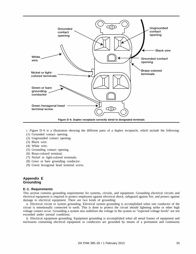
Figure D–6. Duplex receptacle correctly wired to designated terminals
i. Figure D–6 is a illustration showing the different parts of a duplex receptacle, which include the following:(1) Grounded contact opening.(2) Ungrounded contact opening.(3) Black wire.(4) White wire.(5) Grounding contact opening.(6) Brass-colored terminal.(7) Nickel or light-colored terminals.(8) Greer or bare grounding conductor.(9) Green hexagonal head terminal screw.
Appendix EGrounding
E–1. RequirementsThis section contains grounding requirements for systems, circuits, and equipment. Grounding electrical circuits andelectrical equipment is required to protect employees against electrical shock, safeguard against fire, and protect againstdamage to electrical equipment. There are two kinds of grounding:
a. Electrical circuit or system grounding. Electrical system grounding is accomplished when one conductor of thecircuit is intentionally connected to earth. This is done to protect the circuit should lightning strike or other highvoltage contact occur. Grounding a system also stabilizes the voltage in the system so "expected voltage levels" are notexceeded under normal conditions.
b. Electrical equipment grounding. Equipment grounding is accomplished when all metal frames of equipment andenclosures containing electrical equipment or conductors are grounded by means of a permanent and continuous
33DA PAM 385–26 • 1 February 2013

connection or bond. The equipment grounding conductor provides a path for dangerous fault current to return to thesystem ground at the supply source of the circuit should an insulation failure take place. If installed properly, theequipment grounding conductor is the current path that enables protective devices, such as circuit breakers and fuses, tooperate when a fault occurs. Figure E–1 illustrates both types of grounding.
Figure E–1. System and equipment grounding
E–2. Parts of system and equipment groundinga. Figure E–1 is an illustration showing and describing parts of system and equipment grounding, which include the
following:(1) Primary (transformer).(2) Transformer secondary.(3) Grounded conductor or neutral.(4) System grounding.(5) Service entrance.(6) Equipment grounding conductor.(7) Equipment grounding.b. Most metallic raceways, cable sheaths, and cable armor which are continuous and utilize proper fittings may
serve as the equipment grounding conductor. A separate grounding conductor is needed when plastic conduit, non-metallic sheathed cable, or other wiring methods are used which are not approved as grounding methods.
34 DA PAM 385–26 • 1 February 2013

Appendix FGrounding PathThe path to ground from circuits, equipment, and enclosures will be permanent and continuous.
F–1. Effective grounding pathEffective grounding path was extracted from NFPA 70 (NEC), Article 250 (Grounding), which is more complete andfundamental to the understanding of electrical safety. It states that the path to ground—
a. “Shall be permanent and continuous." (If the path is installed in such a way that damage, corrosion, loosening, orso forth may impair the continuity during the life of the installation, then shock and burn hazards will develop.)
b. "Shall have capacity to conduct safely any fault current likely to be imposed on it." (Fault currents may be manytimes normal currents, and such high currents may melt or burn metal at points of poor conductivity. These hightemperatures may be a hazard in themselves, and they may destroy the continuity of the ground fault path.)
c. "Shall have sufficiently low impedance to limit the voltage to ground and to facilitate the operation of the circuitprotective devices in the circuit." (If the ground fault path has a high impedance, there will be hazardous voltageswhenever fault currents attempt to flow. Also, if the impedance is high, the fault current will be limited to some valueso low that the fuse or circuit breaker will not operate promptly, if at all.)
F–2. Safe grounding pathsIt is important to remember the following regarding safe grounding paths:
a. The fault current in AC circuits will be limited by the sum of resistance and reactance, and the only low-reactance path is that which closely follows the circuit conductors.
b. If a metallic raceway system is used, make sure that the metallic system is continuous and permanent.c. In cases where a metallic raceway system is not used, provide a green or bare equipment-grounding conductor
close to the supply conductors to assure that all enclosures are bonded together and to the source.
Appendix GStandards for Electrical Protective Equipment
G–1. Electrical protective equipmentTable G–1 shows the standards for electrical protective equipment.
Table G–1Standards for electrical protective equipment
Subject Number Title
Head protection ANSI/ISEA Z89.1- 2009 American National Standard for Industrial Head Protection
Eye and face protection ANSI/ISEA Z87.1- 2010 American National Standard for Occupational and Educational PersonalEye and Face Protection Devices
Gloves – rubber ASTM D120 –09 Standard Specification for Rubber Insulating Gloves
Sleeves ASTM D1051 - 08 Standard Specification for Rubber Insulating Sleeves
Gloves and sleeves ASTM F496 - 08 Standard Specification for In-Service Care of Insulating Gloves andSleeves
Leather protectors ASTM F696 - 06 (2011) Standard Specification for Leather Protectors for Rubber InsulatingGloves and Mittens
Footwear ASTM F1117 - 03 (2008)ASTM F2412 - 11ASTM F2413 - 11
Standard Specification for Dielectric FootwearStandard Test Methods for Foot ProtectionStandard Specification for Performance Requirements for Protective(Safety) Toe Cap Footwear
Visual inspection ASTM F1236 - 96(2012) Standard Guide for Visual Inspection of Electrical Protective Rubber Prod-ucts
Apparel ASTM F1506 - 10a Standard Performance Specification for Flame Resistant and Arc RatedTextile Materials for Wearing Apparel for Use by Electrical Workers Ex-posed to Momentary Electric Arc and Related Thermal Hazards
Raingear ASTM F1891 - 12 Standard Specification for Arc and Flame Resistant Rainwear
35DA PAM 385–26 • 1 February 2013

Table G–1Standards for electrical protective equipment—Continued
Face protective products ASTM F2178 - 12 Standard Test Method for Determining the Arc Rating and StandardSpecification for Face Protective Products
Fall protection ASTM F887 - 12e1 Standard Specifications for Personal Climbing Equipment
Rubber protective products – vis-ual inspection
ASTM F1236 - 96 (2012) Standard Guide for Visual Inspection of Electrical Protective Rubber Prod-ucts
Aprons ASTM F2677- 08a Standard Specification for Electrically Insulating Aprons
G–2. Related protective equipmentTable G–2 shows the standards for other related protective equipment.
Table G–2Standards for Other Related Protective Equipment
Subject Number Title
Arc protective blankets ASTM F2676 - 09 Standard Test Method for Determining the Protective Performance of anArc Protective Blanket for Electric Arc Hazards
Blankets ASTM D1048 - 12 Standard Specification for Rubber Insulating Blankets
Blankets – in-service care ASTM F479 - 06 (2011) Standard Specification for the Service Care of Insulating Blankets
Covers ASTM D1049 - 98 (2010) Standard Specification for Rubber Insulating Covers
Fiberglass rods – live line tools ASTM F711 - 02 (2007) Standard Specification for Fiberglass Reinforced Plastic (FRP) Rod andTube Used in Live Line Tools
Insulated hand tools ASTM F1505 - 10 Standard Specification for Insulated and Insulating Hand Tools
Ladders ANSI ASC A14.1 - 2007 American National Standard for Ladders –Wood Safety Requirements
ANSI ASC A14.3 - 2008 American National Standard for Ladders –Fixed-Safety Requirements
ANSI ASC A14.4 - 2009 American National Standard Safety Requirements for Job Made WoodenLadders
ANSI ASC A14.5 - 2007 American National Standard for Ladders – Portable Reinforced Plastic-Safety Requirements
Line hose ASTM D1050-05 (2011) Standard Specification for Rubber Insulating Line Hose
Line hose and covers – in-servicecare
ASTM F478 - 09 Standard Specification for In Service Care of Insulating Line Hose andCovers
Plastic guard ASTM F712 - 06 (2011) Standard Test Methods and Specifications for Electrically Insulating Plas-tic Guard Equipment for Protection of Workers
Polyvinyl chloride (PVC) sheeting ASTM F1742 – 03 (2011) Standard Specification for PVC Insulating Sheeting
Safety signs and tags ANSI Z535 series Safety Color Code (series of standards for safety signs and tags)
Shield performance on live linetools
ASTM F2522 - 12 Standard Test Method for Determining the Protective Performance of aShield Attached on Live Line Tools or on Racking Rods for Electric ArcHazards
Temporary protective grounds in-service testing
ASTM F2249 – 03 (2009) Standard Specification for In-Service Test Methods for Temporary Groun-ding Jumper Assemblies Used on De-energized Electric Power Lines andEquipment
Temporary protective grounds –test specification
ASTM F855 - 09 Standard Specifications for Temporary Protective Grounds to Be Used onDe-energized Electric Power Lines and Equipment
Appendix HHazard Analysis Factors Prior to Performing Electrical Work
H–1. GeneralThe following list is not all inclusive, but provides suggestions for factors to consider. Remember that one goal of thepre-job brief is to assure that all workers understand the hazards and controls.
36 DA PAM 385–26 • 1 February 2013

H–2. Factorsa. Describe the modes of electrical work that will be conducted during this work activity (for example, de-energized
work, verification of zero energy, energized work, tuning and adjusting).b. What electrical hazards will the worker encounter, or be exposed to during each step of the work? Examples
include shock, thermal burn, and arc flash.c. What are the shock and arc flash boundaries?d. How close will any portion of the worker(s) body come to exposed electrical conductors? Which of the
boundaries, if any, will the worker cross?e. At what steps or phases of this activity is the worker(s) exposed to electrical hazards?f. What can go wrong, or what mistake could be made, that would expose the worker to an electrical hazard?g. Is a second person or safety watch required for any steps of this activity?h. If so, what are their specific duties and training and/or knowledge requirements?i. What electrical PPE is required? Does it require certification? If so, is it current?j. Do the workers have training to inspect and use the electrical PPE?k. Are there nonelectrical hazards that have controls that could conflict with the electrical hazard controls? Specific
examples include uniforms that contain nylon, clean room coats, or respirators that are not arc flash rated, and chemicalor glove box gloves that are not voltage rated. If so, how will this be resolved?
l. Is an SOP or EEWP required for this work?m. Is there a point in the work where the electrical hazard(s) have been mitigated and the electrical PPE can be
removed?n. Are there multiple groups, contractors, or crafts involved? How is this managed to assure communication and
understanding among all groups?o. Does this work require the removal of jewelry, badges, or other dangling objects?p. Can the electrical energy result in a noise hazard?q. What could go wrong that would require a pause or stop work?r. What workers are cardiopulmonary resuscitation and/or automated external defibrillation trained? Where is the
nearest automated external defibrillation equipment?s. How would an electrical shock or arc flash injury be handled?t. Where is the nearest phone? How long would it take for emergency response to arrive?u. Are any special tools or test equipment to be used? Are they adequately voltage rated, if necessary?v. How will any electrical energy stored in capacitors be removed?w. Are there other workers in the vicinity that could be endangered by any exposed electrical hazards, such as arc
flash, noise, electromagnetic fields, and so forth?x. How will access to the electrical work be controlled?
Appendix IGuidelines for Equipment Inspection and Approval by the Authority Having Jurisdiction
I–1. GeneralIn-house built, other manufacturer, and/or modified NRTL-listed electrical equipment must be examined. Check theitems listed below as applicable.
I–2. External inspectiona. Enclosure.(1) Operator not exposed to any hazard.(2) Not damaged.(3) Appropriate material.(4) Protects contents from operating environment.(5) Adequate to protect against shock.(6) Contains any arcs, sparks, and electrical explosions.b. Power source.(1) Cords and plugs.(a) Proper voltage and ampacity rating for cord and plug.(b) Grounding conductor included, if required.(c) Not frayed or damaged.(d) Proper wiring of plug.
37DA PAM 385–26 • 1 February 2013

(e) Strain relief on cord.(2) Direct-wired into facility.(a) Proper voltage and ampacity rating for wiring method.(b) Installed in accordance with NFPA 70 (NEC).(c) Proper loading and overcurrent protection in branch circuit.c. Grounding.(1) Ground from cord or other is terminated properly.(2) All noncurrent-carrying exposed metal is bonded properly.(3) All noncurrent-carrying internal subsystems are bonded properly.(4) Equipment ground is run with circuit conductors.(5) Auxiliary ground permitted.(6) Termination checked.d. Foreign power supplies and equipment.(1) Connected to facility power with appropriate adapters.(2) Correct voltage, frequency, and phasing.(3) Correct wire ampacity for use in United States.e. Overcurrent protection. Overcurrent protection located in equipment or branch circuit.f. Marking requirements.(1) Hazards, including stored energy.(2) Power requirements (voltage, current, frequency, power).(3) Make, model, and/or drawing number.(4) Restrictions and limitations of use.g. Other requirements.(1) Adequate documentation.(2) Procedures to use (for example, installation wiring diagram).(3) Training and qualifications.h. Secondary hazards.(1) Radio frequency.(2) Dielectric or magnetic fields.(3) Infrared, visible or ultraviolet.(4) X-rays.(5) Fire, electrical explosion.
I–3. Internal inspectiona. Internal wiring.(1) Polarity.(2) Phasing.(3) Landing of ground.(4) Line voltage and high voltage separate from low voltage.(5) Wiring terminals and leads.(6) Wire size.(7) Proper dielectric.(8) Clearance/creepage distances for high voltage.(9) Listed conductors, if applicable.b. Other internal issues.(1) Neat workmanship.(2) Listed components used, if applicable.(3) Proper management of conductors.(4) Free of sharp edges.(5) Proper cooling.(6) Automatic discharge of high-voltage capacitor.c. Tests performed.(1) Ground continuity (less than 1 ohm).(2) Polarization of cord and plug.(3) Auto discharge of high-voltage capacitor.(4) Functional tests (for example, GFCI and emergency shut-off).
38 DA PAM 385–26 • 1 February 2013

d. Failure analysis.(1) Effect of ground fault.(2) Effect of short circuit.(3) Effect of interlock failure.(4) Effect of overload.(5) Effect of incorrect setting.e. Maintenance. Any safety issues with access and maintenance.
39DA PAM 385–26 • 1 February 2013

Glossary
Section IAbbreviations
ACalternating current
AHJauthority having jurisdiction
ANSIAmerican National Standards Institute
ARArmy regulation
ASTMAmerican Society for Testing and Materials International
BSBritish Standard
CEEuropean Conformity
CFRCode of Federal Regulations
cal/cm^2calories/square centimeters
cmcentimeter
DADepartment of the Army
DCdirect current
EEWPEnergized Electrical Work Permit
EUEuropean Union
ftfoot (feet)
FPEforce provider expeditionary
FRfire-resistant
FRP (publication)fiberglass-reinforced plastic
GFCIground fault circuit interrupter
40 DA PAM 385–26 • 1 February 2013

Hzhertz
ininch
ISEAInternational Safety Equipment Association
kVkilovolt
mmeter(s)
mAmilliamperes
mmmillimeter
NECNational Electrical Code
NFPANational Fire Protection Association
NRTLNationally Recognized Testing Laboratory
O&M (publication)operation and maintenance
Pam (publication)pamphlet
PPEpersonal protective equipment
PVCpolyvinyl chloride
SOPstandard operating procedure
TSEWGTri-Service Electrical Working Group
U.S.United States
UFCUnified Facilities Criteria
USCUnited States Code
Vvolt
41DA PAM 385–26 • 1 February 2013

Section IITerms
AmpacityThe current, in amperes, that a conductor can carry continuously under the conditions of use without exceeding itstemperature rating.
ApplianceUtilization equipment, generally other than industrial, that is normally built in standardized sizes or types and isinstalled or connected as a unit to perform one or more functions such as clothes washing, air conditioning, foodmixing, deep frying, and so forth.
Arc flash hazardA dangerous condition associated with the possible release of energy caused by an electric arc.
Arc flash hazard analysisA study investigating a worker’s potential exposure to arc flash energy, conducted for the purpose of injury preventionand the determination of safe work practices, arc flash protection boundary, and the appropriate levels of PPE.
Arc flash suitA complete fire-rated clothing and equipment system that covers the entire body, except for the hands and feet. Thisincludes pants, jacket, and beekeeper-type hood fitted with a face shield.
Attachment plugsA device that, by insertion in a receptacle, establishes a connection between the conductors of the attached flexiblecord and the conductors connected permanently to the receptacle.
Authority having jurisdictionThe organization, office, or individual responsible for approving equipment, materials, an installation, or a procedure.
BarricadeA physical obstruction such as tapes, cones, or A-frame-type wood or metal structures intended to provide a warningabout and to limit access to a hazardous area.
BarrierA physical obstruction that is intended to prevent contact with equipment or energized electrical conductors and circuitparts or to prevent unauthorized access to a work area.
Branch circuitsThe circuit conductors between the final overcurrent device protecting the circuit and the outlet(s).
Boundary, arc flash protectionWhen an arc flash hazard exists, an approach limit at a distance from a prospective arc source within which a personcould receive a second degree burn if an electrical arc flash were to occur.
Boundary, limited approachAn approach limit at a distance from an exposed, energized electrical conductor or circuit part within which a shockhazard exists.
Boundary, prohibited approachAn approach limit at a distance from an exposed, energized electrical conductor or circuit part within which work isconsidered the same as making contact with the electrical conductor or circuit part.
Boundary, restricted approachAn approach limit at a distance from an exposed, energized electrical conductor or circuit part within which there is anincreased risk of shock, due to electrical arc over combined with inadvertent movement, for personnel working in closeproximity to the energized electrical conductor or circuit part.
42 DA PAM 385–26 • 1 February 2013

Circuit breakerA device designed to open and close a circuit by nonautomatic means and to open the circuit automatically on apredetermined overcurrent without damage to itself when properly applied within its rating.
Conductor-AMaterial (usually a wire, cable, or bus bar) for carrying an electric current.
De-energizedFree from any electrical connection to a source of potential difference and from electrical charge; not having a potentialdifferent from that of the earth.
DeviceA unit of an electrical system that carries or controls electric energy as its principal function.
Electrical hazardA dangerous condition such that contact or equipment failure can result in electric shock, arc flash burn, thermal burn,or blast.
Electrical safetyRecognizing hazards associated with the use of electrical energy and taking precautions so that hazards do not causeinjury or death.
Electrical safe work conditionA state in which an electrical conduct or circuit part has been disconnected from energized parts, locked and/or taggedin accordance with established standards, tested to ensure the absence of voltage, and grounded, if determinednecessary.
EnergizedElectrically connected to or having a source of voltage.
Exposed (as applied to live parts)Circuit is in such a position that, in case of failure of supports or insulation, contact with another circuit may result.Capable of being inadvertently touched or approached nearer than a safe distance by a person. It is applied to parts thatare not suitably guarded, isolated, or insulated.
FusesAn overcurrent protective device with a circuit-opening fusible part that is heated and severed by the passage ofovercurrent through it.
GroundedConnected to ground or to a conductive body that extends the ground connection.
Ground conductorA system or circuit conductor that is intentionally grounded.
Ground faultAn unintentional, electrically conducting connection between an ungrounded conductor of an electrical circuit and thenormally noncurrent-carrying conductors, metallic enclosures, metallic raceways, metallic equipment, or earth.
Ground fault circuit interrupterA device intended for the protection of personnel that functions to de-energize a circuit or portion thereof within anestablished period of time when a current to ground exceeds the values established for a Class A device.
InsulatedSeparated from other conducting surfaces by a dielectric (including air space) offering a high resistance to the passageof current.
Live partsEnergized conductive components.
43DA PAM 385–26 • 1 February 2013

OutletA point on the wiring system at which current is taken to supply utilization equipment.
OvercurrentAny current in excess of the rated current of equipment or the ampacity of a conductor. It may result from overload,short circuit, or ground fault.
PanelboardA single panel or group of panel units designed for assembly in the form of a single panel, including buses andautomatic overcurrent devices, and equipped with or without switches for the control of light, heat, or power circuits;designed to be placed in a cabinet or cutout box placed in or against a wall, partition, or other support; and accessibleonly from the front.
Qualified personOne who has skills and knowledge related to the construction and operation of electrical equipment and installationsand has received safety training to recognize and avoid the hazards involved.
ReceptacleA contact device installed at the outlet for the connection of an attachment plug. A single receptacle is a single contactdevice with no other contact device on the same yoke. A multiple receptacle is two or more contact devices on thesame yoke.
ServiceThe conductors and equipment for delivering electric energy from the serving utility to the wiring system of thepremises served.
Service conductorsThe conductors from the service point to the service disconnecting means.
Service dropThe overhead service conductors from the last pole or other aerial support to, and including, the splices, if any,connecting to the service entrance conductors at the building or other structure.
Shock hazardA dangerous condition associated with the possible release of energy caused by contact or approach to energizedelectrical conductors or circuit parts.
SwitchboardA large single panel, frame, or assembly of panels on which are mounted, on the face, back, or both, switches,overcurrent and other protective devices, buses, and, usually, instruments. Switchboards are generally accessible fromthe rear as well as from the front and are not intended to be installed in cabinets.
Switching deviceA device designed to close, open, or both, one or more electric circuit(s).
Unqualified personA person who is not a qualified person.
Voltage (of a circuit)T h e g r e a t e s t r o o t - m e a n - e x p o s u r e ( e f f e c t i v e ) d i f f e r e n c e o f p o t e n t i a l b e t w e e n a n y t w o c o n d u c t o r s o f t h e c i r c u i tconcerned.
Voltage, nominalA nominal value assigned to a circuit or system for the purpose of conveniently designating its voltage class (for
44 DA PAM 385–26 • 1 February 2013

example, 120/240V, 480Y/277V, or 600V). The actual voltage at which a circuit operates can vary from the nominalwithin a range that permits satisfactory operation of equipment.
Voltage to groundFor grounded circuits, the voltage between the given conductor and that point or conductor of the circuit that isgrounded; for ungrounded circuits, the greatest voltage between the given conductor and any other conductor of thecircuit.
Section IIISpecial Abbreviations and TermsThis section contains no entries.
45DA PAM 385–26 • 1 February 2013

UNCLASSIFIED PIN 103331–000