SAFETY RECOGNIZED CERAMIC CAPACITORS - … · DEJ Series -Based on the Electrical Appliance and...
28
Murata Manufacturing Co., Ltd. Cat.No.C80E-5 Safety Recognized Ceramic Capacitors SAFETY RECOGNIZED CERAMIC CAPACITORS Please read CAUTION and Notice in this catalog for safety. This catalog has only typical specifications. Therefore you are requested to approve our product specification or to transact the approval sheet for product specification, before your ordering. C80E5.pdf 02.2.26
Transcript of SAFETY RECOGNIZED CERAMIC CAPACITORS - … · DEJ Series -Based on the Electrical Appliance and...

MurataManufacturing Co., Ltd. Cat.No.C80E-5
Safety Recognized Ceramic Capacitors
SAFETYRECOGNIZEDCERAMICCAPACITORS
Please read CAUTION and Notice in this catalog for safety. This catalog has only typical specifications. Therefore you are requestedto approve our product specification or to transact the approval sheet for product specification, before your ordering.
C80E5.pdf 02.2.26
1
2
3
4
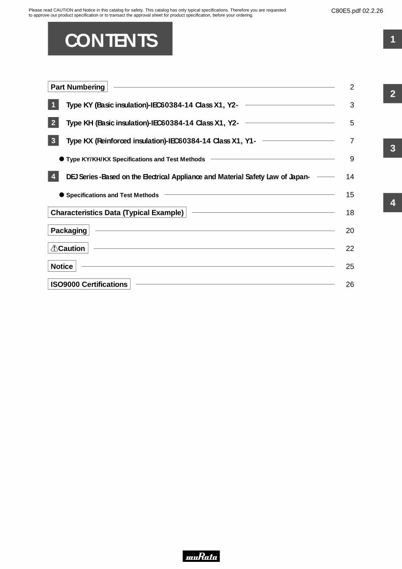
Part Numbering 2
Type KY (Basic insulation)-IEC60384-14 Class X1, Y2- 3
Type KH (Basic insulation)-IEC60384-14 Class X1, Y2- 5
Type KX (Reinforced insulation)-IEC60384-14 Class X1, Y1- 7
Type KY/KH/KX Specifications and Test Methods 9
DEJ Series -Based on the Electrical Appliance and Material Safety Law of Japan- 14
Specifications and Test Methods 15
Characteristics Data (Typical Example) 18
Packaging 20
!Caution 22
Notice 25
ISO9000 Certifications 26
CONTENTS 1
2
3
4
Please read CAUTION and Notice in this catalog for safety. This catalog has only typical specifications. Therefore you are requestedto approve our product specification or to transact the approval sheet for product specification, before your ordering.
C80E5.pdf 02.2.26

t
102
y
M
q
DE
u
N3
r
KH
e
E3
w
2
i
A
o
qProduct ID
wSeries Category
eTemperature Characteristics
rRated Voltage/Safety Standard Recognized Type
Code
E2
KH
KY
KX
yCapacitance Tolerance
Capacitance ToleranceCode
K
M
Z
T10%
T20%
W80%, Y20%
ContentsOutlineCode
1
2
J
Cap.Changeor Temp. Coeff.
TemperatureRange
TemperatureCharacteristics
Rated Voltage
Code
B3
E3
F3
1X
T10%
W20%,Y55%
W30%,Y80%
W350 to Y1000ppm/D
Y25 to W85D
W20 to W85D
B
E
F
SL
Safety StandardRecognized
AC250V(r.m.s.)
IEC60384-14 Class X1, Y1
IEC60384-14 Class X1, Y2
"Products which are based on the Electrical Appliance and
Material Safety Law of Japan"
AC250V
X1, Y2; AC250V, (Safety Standard Recognized Type KH)
X1, Y2; AC250V, (Safety Standard Recognized Type KY)
X1, Y1; AC250V, (Safety Standard Recognized Type KX)
Product ID
DEHigh-voltage (250V - 6.3kV) /
Safety Standard Recognized Ceramic Capaictors
uLead Style
LeadStyleCode
A2
A3
A5
B2
B3
B5
C3
D3
N2
N3
N5
N7
P3
LeadSpacing
Pitch ofComponents
Lead Diameter
Dimensions(mm)
5
7.5
10
5
7.5
10
7.5
7.5
5
7.5
10
7.5
7.5
ø0.6T0.05
ø0.6W0.1,Y0.05
ø0.6T0.05
ø0.6W0.1, Y0.05
ø0.6T0.05
ø0.6T0.05
ø0.6T0.05
ø0.6W0.1, Y0.05
ø0.6T0.05
ø0.6T0.05
Y
Y
Y
Y
12.7
15
25.4
30
15
iPackaging
PackagingCode
A
B
Ammo Pack
Bulk
o Part Numbering The structure of the "Global Part Numbers" that have been adopted since June 2001 and the meaning of each code are described herein.If you have any questions about details, inquire at your usual Murata sales office or distributor.( )
2
(Global Part Number)
Safety Standard Recognized Ceramic Capacitors
tCapacitance
Expressed by three figures. The unit is pico-farad(pF). The first and second figures are significant digits, and the third figure expresses the number of zeros which follow the two numbers.If there is a decimal point, it is expressed by the capital letter "R". In this case, all figures are significant digits.
oIndividual Specification
In case part number cannot be identified without "Individual Specification", it is added at the end of part number.
In case of Electrical Appliance and Material Safety Law of Japan, first three digit (qProduct ID and wSeries Category) express "Series Name".In case of Safety Recognized Capacitors, first three digit express product code. The following forth figure expresses recognized type shown in rSafety Standard Recognized type column.
VerticalCrimpLong
VerticalCrimpLong
VerticalCrimpShort
Straight Long
Straight Short
VerticalCrimpTaping
Straight Taping
ApplicationIndividual SpecificationCode
A01
M01
Small size
Simplicity marking,
Dielectric strength : AC2000V
Type KX
Type KY
Please read CAUTION and Notice in this catalog for safety. This catalog has only typical specifications. Therefore you are requestedto approve our product specification or to transact the approval sheet for product specification, before your ordering.
C80E5.pdf 02.2.26
Please read CAUTION and Notice in this catalog for safety. This catalog has only typical specifications. Therefore you are requestedto approve our product specification or to transact the approval sheet for product specification, before your ordering.
C80E5.pdf 02.2.26
3
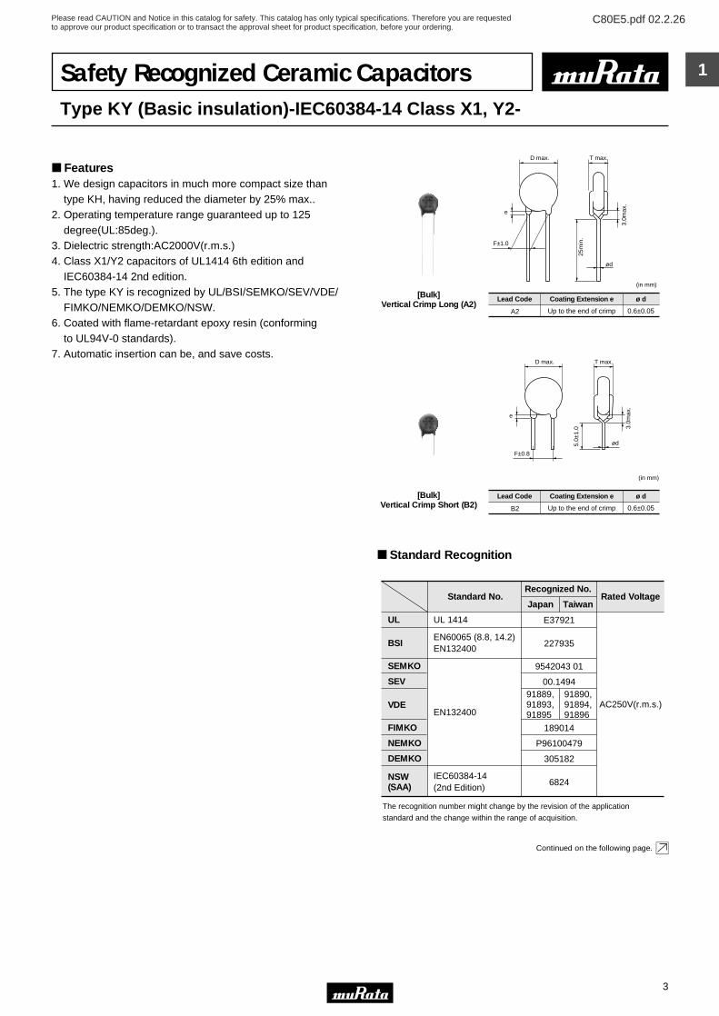
1Safety Recognized Ceramic CapacitorsType KY (Basic insulation)-IEC60384-14 Class X1, Y2-
Features1. We design capacitors in much more compact size than type KH, having reduced the diameter by 25% max..2. Operating temperature range guaranteed up to 125 degree(UL:85deg.).3. Dielectric strength:AC2000V(r.m.s.)4. Class X1/Y2 capacitors of UL1414 6th edition and IEC60384-14 2nd edition.5. The type KY is recognized by UL/BSI/SEMKO/SEV/VDE/ FIMKO/NEMKO/DEMKO/NSW.6. Coated with flame-retardant epoxy resin (conforming to UL94V-0 standards).7. Automatic insertion can be, and save costs.
ød
F±1.0
(in mm)
D max.
25m
in.
e
T max.
3.0m
ax.
Lead Code Coating Extension e
A2 Up to the end of crimp
ø d
0.6±0.05
[Bulk]Vertical Crimp Long (A2)
ød
F±0.8
D max.
e
T max.
3.0m
ax.
5.0±
1.0
(in mm)
Lead Code Coating Extension e
B2 Up to the end of crimp
ø d
0.6±0.05
[Bulk]Vertical Crimp Short (B2)
Standard Recognition
UL
BSI
SEMKO
SEV
VDE
FIMKO
NEMKO
DEMKO
NSW(SAA)
Standard No.Recognized No.
Rated Voltage
AC250V(r.m.s.)
The recognition number might change by the revision of the application
standard and the change within the range of acquisition.
UL 1414
EN60065 (8.8, 14.2)EN132400
EN132400
IEC60384-14(2nd Edition)
E37921
227935
9542043 01
00.149491889, 91890,91893, 91894,91895 91896
189014
P96100479
305182
6824
Japan Taiwan
Continued on the following page.
Please read CAUTION and Notice in this catalog for safety. This catalog has only typical specifications. Therefore you are requestedto approve our product specification or to transact the approval sheet for product specification, before your ordering.
C80E5.pdf 02.2.26
4
1
Continued from the preceding page.
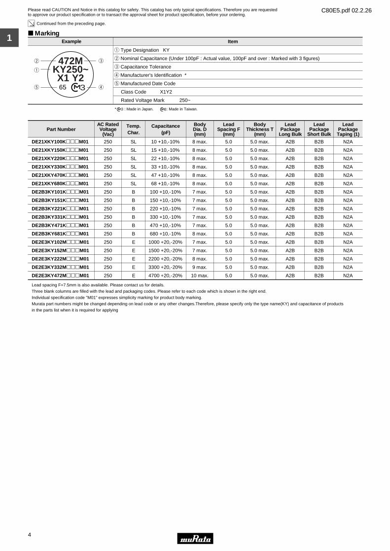
Marking
t Manufactured Date Code
Class Code X1Y2
Rated Voltage Mark 250~
e Capacitance Tolerance
w Nominal Capacitance (Under 100pF : Actual value, 100pF and over : Marked with 3 figures)
q Type Designation KY
r Manufacturer's Identification ∗
472MKY250~X1 Y2
365
q
w e
rt
Example Item
∗ : Made in Japan. : Made in Taiwan.3 8
Part NumberAC RatedVoltage
(Vac)
Temp.Char.
Capacitance(pF)
BodyDia. D(mm)
LeadSpacing F
(mm)
BodyThickness T
(mm)
LeadPackage
Long Bulk
LeadPackage
Short Bulk
LeadPackageTaping (1)
DE21XKY100KpppM01 250 SL 10 +10,-10% 8 max. 5.0 5.0 max. A2B B2B N2A
DE21XKY150KpppM01 250 SL 15 +10,-10% 8 max. 5.0 5.0 max. A2B B2B N2A
DE21XKY220KpppM01 250 SL 22 +10,-10% 8 max. 5.0 5.0 max. A2B B2B N2A
DE21XKY330KpppM01 250 SL 33 +10,-10% 8 max. 5.0 5.0 max. A2B B2B N2A
DE21XKY470KpppM01 250 SL 47 +10,-10% 8 max. 5.0 5.0 max. A2B B2B N2A
DE21XKY680KpppM01 250 SL 68 +10,-10% 8 max. 5.0 5.0 max. A2B B2B N2A
DE2B3KY101KpppM01 250 B 100 +10,-10% 7 max. 5.0 5.0 max. A2B B2B N2A
DE2B3KY151KpppM01 250 B 150 +10,-10% 7 max. 5.0 5.0 max. A2B B2B N2A
DE2B3KY221KpppM01 250 B 220 +10,-10% 7 max. 5.0 5.0 max. A2B B2B N2A
DE2B3KY331KpppM01 250 B 330 +10,-10% 7 max. 5.0 5.0 max. A2B B2B N2A
DE2B3KY471KpppM01 250 B 470 +10,-10% 7 max. 5.0 5.0 max. A2B B2B N2A
DE2B3KY681KpppM01 250 B 680 +10,-10% 8 max. 5.0 5.0 max. A2B B2B N2A
DE2E3KY102MpppM01 250 E 1000 +20,-20% 7 max. 5.0 5.0 max. A2B B2B N2A
DE2E3KY152MpppM01 250 E 1500 +20,-20% 7 max. 5.0 5.0 max. A2B B2B N2A
DE2E3KY222MpppM01 250 E 2200 +20,-20% 8 max. 5.0 5.0 max. A2B B2B N2A
DE2E3KY332MpppM01 250 E 3300 +20,-20% 9 max. 5.0 5.0 max. A2B B2B N2A
DE2E3KY472MpppM01 250 E 4700 +20,-20% 10 max. 5.0 5.0 max. A2B B2B N2A
Lead spacing F=7.5mm is also available. Please contact us for details.
Three blank columns are filled with the lead and packaging codes. Please refer to each code which is shown in the right end.
Individual specification code "M01" expresses simplicity marking for product body marking.
Murata part numbers might be changed depending on lead code or any other changes.Therefore, please specify only the type name(KY) and capacitance of products
in the parts list when it is required for applying

Please read CAUTION and Notice in this catalog for safety. This catalog has only typical specifications. Therefore you are requestedto approve our product specification or to transact the approval sheet for product specification, before your ordering.
C80E5.pdf 02.2.26
5
2
Safety Recognized Ceramic CapacitorsType KH (Basic insulation)-IEC60384-14 Class X1, Y2-
Features1. Operating temperature range guaranteed up to 125 degree(UL/CSA:85deg.).2. Dielectric strength:AC2600V(r.m.s.)3. Class X1/Y2 capacitors of UL1414 6th edition and IEC60384-14 2nd edition.4. The type KH is recognized by UL/CSA/BSI/SEMKO/SEV/ VDE/FIMKO/NEMKO/DEMKO/NSW.5. Coated with flame-retardant epoxy resin (conforming to UL94V-0 standards).6. Automatic insertion can be, and save costs.
ød
F±1.0
(in mm)
D max.
25m
in.
e
T max.
3.0m
ax.
Lead Code Coating Extension e
A3 Up to the end of crimp
ø d
0.6±0.05
[Bulk]Vertical Crimp Long (A3)
ød
F±0.8
D max.
e
T max.
3.0m
ax.
5.0±
1.0
(in mm)
Lead Code Coating Extension e
B3 Up to the end of crimp
ø d
0.6±0.05
[Bulk]Vertical Crimp Short (B3)
Standard Recognition
UL
CSA
BSI
SEMKO
SEV
VDE
FIMKO
NEMKO
DEMKO
NSW(SAA)
• The recognition number might change by the revision of the application
standard and the change within the range of acquisition.
• CCEE (Chinese Safety Standard) Safety Standard is also available
as special specification. Please contact us for details.
Standard No.
UL1414
C22.2 No.1
EN60065 (8.8, 14.2)EN132400
EN132400
IEC60384-14(2nd Edition)
Recognized No.
Japan Taiwan
E37921
LR36214
227636
9735044/01-02
98, 5 50212
83663, 83665,83667
198418
P97102089
113878A/DK 98-01362
6529
LR44559
83664, 83666,83668
RatedVoltage
AC250V(r.m.s.)
Marking
q Type Designation KH
w Nominal Capacitance(Marked with 3 figures)
e Capacitance Tolerance
r Manufacturer's Identification ∗t Manufactured Date Code
UL Approval Mark
CSA Approval Mark
BSI Approval Mark BS415
SEMKO Approval Mark
SEV Approval Mark
VDE Approval Mark
FIMKO Approval Mark
NEMKO Approval Mark
DEMKO Approval Mark
Class Code (Except for CSA) X1Y2
Rated Voltage Mark 250~
FI
N
D
KH472MX1Y2BS415
q
w
e
r
t
3
65MJ502
250~
∗ : Made in Japan. : Made in Taiwan.3 8
Example Item
FI
N
D
MJ502
Please read CAUTION and Notice in this catalog for safety. This catalog has only typical specifications. Therefore you are requestedto approve our product specification or to transact the approval sheet for product specification, before your ordering.
C80E5.pdf 02.2.26
6
2
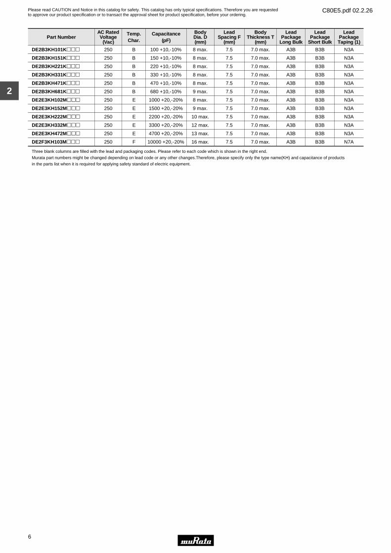
Part NumberAC RatedVoltage
(Vac)
Temp.Char.
Capacitance(pF)
BodyDia. D(mm)
LeadSpacing F
(mm)
BodyThickness T
(mm)
LeadPackage
Long Bulk
LeadPackage
Short Bulk
LeadPackageTaping (1)
DE2B3KH101Kppp 250 B 100 +10,-10% 8 max. 7.5 7.0 max. A3B B3B N3A
DE2B3KH151Kppp 250 B 150 +10,-10% 8 max. 7.5 7.0 max. A3B B3B N3A
DE2B3KH221Kppp 250 B 220 +10,-10% 8 max. 7.5 7.0 max. A3B B3B N3A
DE2B3KH331Kppp 250 B 330 +10,-10% 8 max. 7.5 7.0 max. A3B B3B N3A
DE2B3KH471Kppp 250 B 470 +10,-10% 8 max. 7.5 7.0 max. A3B B3B N3A
DE2B3KH681Kppp 250 B 680 +10,-10% 9 max. 7.5 7.0 max. A3B B3B N3A
DE2E3KH102Mppp 250 E 1000 +20,-20% 8 max. 7.5 7.0 max. A3B B3B N3A
DE2E3KH152Mppp 250 E 1500 +20,-20% 9 max. 7.5 7.0 max. A3B B3B N3A
DE2E3KH222Mppp 250 E 2200 +20,-20% 10 max. 7.5 7.0 max. A3B B3B N3A
DE2E3KH332Mppp 250 E 3300 +20,-20% 12 max. 7.5 7.0 max. A3B B3B N3A
DE2E3KH472Mppp 250 E 4700 +20,-20% 13 max. 7.5 7.0 max. A3B B3B N3A
DE2F3KH103Mppp 250 F 10000 +20,-20% 16 max. 7.5 7.0 max. A3B B3B N7A
Three blank columns are filled with the lead and packaging codes. Please refer to each code which is shown in the right end.
Murata part numbers might be changed depending on lead code or any other changes.Therefore, please specify only the type name(KH) and capacitance of products
in the parts list when it is required for applying safety standard of electric equipment.
Please read CAUTION and Notice in this catalog for safety. This catalog has only typical specifications. Therefore you are requestedto approve our product specification or to transact the approval sheet for product specification, before your ordering.
C80E5.pdf 02.2.26
7
3
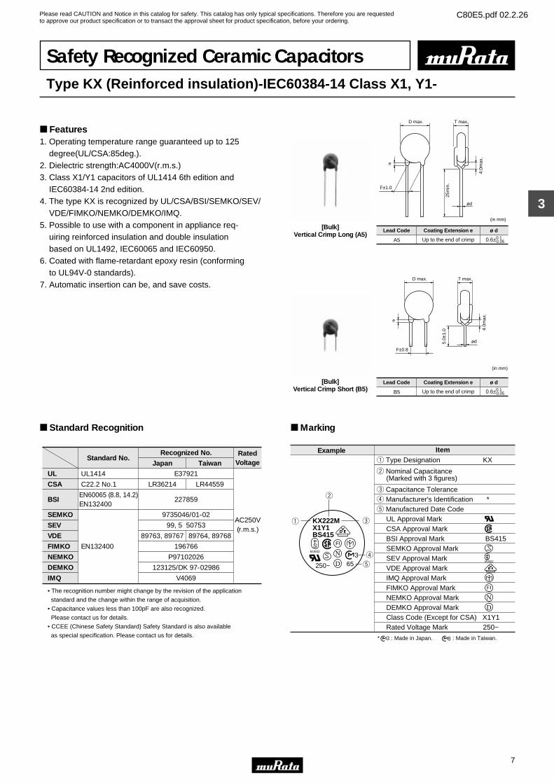
Safety Recognized Ceramic CapacitorsType KX (Reinforced insulation)-IEC60384-14 Class X1, Y1-
Features1. Operating temperature range guaranteed up to 125 degree(UL/CSA:85deg.).2. Dielectric strength:AC4000V(r.m.s.)3. Class X1/Y1 capacitors of UL1414 6th edition and IEC60384-14 2nd edition.4. The type KX is recognized by UL/CSA/BSI/SEMKO/SEV/ VDE/FIMKO/NEMKO/DEMKO/IMQ.5. Possible to use with a component in appliance req- uiring reinforced insulation and double insulation based on UL1492, IEC60065 and IEC60950.6. Coated with flame-retardant epoxy resin (conforming to UL94V-0 standards).7. Automatic insertion can be, and save costs.
ød
F±1.0
(in mm)
D max.
25m
in.
e
T max.
4.0m
ax.
Lead Code Coating Extension e
A5 Up to the end of crimp
ø d
0.6±0.1 0.05
[Bulk]Vertical Crimp Long (A5)
ød
F±0.8
D max.
e
T max.
4.0m
ax.
5.0±
1.0
(in mm)
Lead Code Coating Extension e
B5 Up to the end of crimp
ø d
0.6±0.1 0.05
[Bulk]Vertical Crimp Short (B5)
Standard Recognition
UL
CSA
BSI
SEMKO
SEV
VDE
FIMKO
NEMKO
DEMKO
IMQ
• The recognition number might change by the revision of the application
standard and the change within the range of acquisition.
• Capacitance values less than 100pF are also recognized.
Please contact us for details.
• CCEE (Chinese Safety Standard) Safety Standard is also available
as special specification. Please contact us for details.
Standard No.
UL1414
C22.2 No.1
EN60065 (8.8, 14.2)EN132400
EN132400
Recognized No.
Japan Taiwan
E37921
LR36214
227859
9735046/01-02
99, 5 50753
89763, 89767
196766
P97102026
123125/DK 97-02986
V4069
LR44559
89764, 89768
RatedVoltage
AC250V(r.m.s.)
Marking
FI
N
D
FI
N
D
KX222MX1Y1BS415
q
w
e
r
t
365
MJ502
250~
∗ : Made in Japan. : Made in Taiwan.3 8
Example Item
MJ502
q Type Designation KX
w Nominal Capacitance(Marked with 3 figures)
e Capacitance Tolerancer Manufacturer's Identification ∗t Manufactured Date Code
UL Approval MarkCSA Approval MarkBSI Approval Mark BS415SEMKO Approval MarkSEV Approval MarkVDE Approval MarkIMQ Approval MarkFIMKO Approval MarkNEMKO Approval MarkDEMKO Approval MarkClass Code (Except for CSA) X1Y1Rated Voltage Mark 250~

Please read CAUTION and Notice in this catalog for safety. This catalog has only typical specifications. Therefore you are requestedto approve our product specification or to transact the approval sheet for product specification, before your ordering.
C80E5.pdf 02.2.26
8
3
Part NumberAC RatedVoltage
(Vac)
Temp.Char.
Capacitance(pF)
BodyDia. D(mm)
LeadSpacing F
(mm)
BodyThickness T
(mm)
LeadPackage
Long Bulk
LeadPackage
Short Bulk
LeadPackageTaping (1)
DE1B3KX101Kppp 250 B 100 +10,-10% 9 max. 10.0 8.0 max. A5B B5B N5A
DE1B3KX151Kppp 250 B 150 +10,-10% 9 max. 10.0 8.0 max. A5B B5B N5A
DE1B3KX221Kppp 250 B 220 +10,-10% 9 max. 10.0 8.0 max. A5B B5B N5A
DE1B3KX331Kppp 250 B 330 +10,-10% 9 max. 10.0 8.0 max. A5B B5B N5A
DE1B3KX471Kppp 250 B 470 +10,-10% 9 max. 10.0 8.0 max. A5B B5B N5A
DE1B3KX681Kppp 250 B 680 +10,-10% 10 max. 10.0 8.0 max. A5B B5B N5A
DE1E3KX102MpppA01 250 E 1000 +20,-20% 8 max. 10.0 8.0 max. A5B B5B N5A
DE1E3KX152MpppA01 250 E 1500 +20,-20% 9 max. 10.0 8.0 max. A5B B5B N5A
DE1E3KX222MpppA01 250 E 2200 +20,-20% 10 max. 10.0 8.0 max. A5B B5B N5A
DE1E3KX332MpppA01 250 E 3300 +20,-20% 12 max. 10.0 8.0 max. A5B B5B N5A
DE1E3KX392MpppA01 250 E 3900 +20,-20% 13 max. 10.0 8.0 max. A5B B5B N5A
DE1E3KX472MpppA01 250 E 4700 +20,-20% 15 max. 10.0 8.0 max. A5B B5B N5A
Three blank columns are filled with the lead and packaging codes. Please refer to each code which is shown in the right end.
Murata part numbers might be changed depending on lead code or any other changes.Therefore, please specify only the type name(KX) and capacitance of products
in the parts list when it is required for applying safety standard of electric equipment.
Please read CAUTION and Notice in this catalog for safety. This catalog has only typical specifications. Therefore you are requestedto approve our product specification or to transact the approval sheet for product specification, before your ordering.
C80E5.pdf 02.2.26
Specifications and Test Methods
No. Item Specification Testing Method
To be easily legible
10000MΩ min.
No marked defect on appearance form and dimen-sions are within specified range.
Appearance and Dimensions
Marking
Insulation Resistance (I.R.)
1
2
5
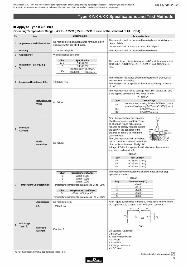
The insulation resistance shall be measured with DC500±50Vwithin 60±5 s of charging.The voltage shall be applied to the capacitor through a resistorof 1MΩ.
The capacitor shall be inspected by naked eyes.
The capacitor shall be inspected by naked eyes for visible evi-dence of defect.Dimensions shall be measured with slide calipers.
Within specified tolerance.Capacitance3
Dissipation Factor (D.F.)Q
4
The capacitance, dissipation factor and Q shall be measured at20˚C with 1±0.1kHz(char. SL : 1±0.1MHz) and AC5V (r.m.s.)max.
No failure.
Dielectric Strength
Between LeadWires
6
The capacitor shall not be damage when Test voltage of Table1 are applied between the lead wires for 60 s.
No failure.BodyInsulation
First, the terminals of the capacitor shall be connected together. Then, as shown in Figure right, a metal foil shall be closely wrapped around the body of the capacitor to the distance of about 3 to 4mm from each terminal.Then,the capacitor shall be insertedinto a container filled with metal balls of about 1mm diameter. Finally, AC voltage of Table 2 is applied for 60 s between the capacitorlead wires and metal balls.
Temperature characteristic guarantee is -25 to +85°C
Temperature characteristic guarantee is +20 to +85°C
Temperature Characteristics7
The capacitance measurement shall be made at each stepspecified in Table 3.
No marked defect.
1000MΩ min.
Per Item 6.
Discharge Test (1)
Appearance
I.R.
DielectricStrength
8
As in Figure 1, discharge is made 50 times at 5 s intervals fromthe capacitor (Cd) charged at DC voltage of specified.
Ct: Capacitor under testCd: 0.001µFS: High-voltage switchR1: 1000ΩR2: 100MΩR3: Surge resistanceVs: DC10kV
Continued on the following page.
Char.B, E
F
SL
D.F.V2.5%D.F.V5.0%
QU400+20C*1(CF30pF)QU1000 (CU30pF)
Specification
Step12345
+20±2-25±2+20±2+85±2+20±2
Temperature (ºC)
Metalfoil about
3 to 4mm
Metalballs
Vs
R3 R1
R2
S
CdCt
<Table.3>
<Table.1>
Fig.1
Apply to Type KY/KH/KXOperating Temperature Range : -25 to +125°C (-25 to +85°C in case of the standard of UL / CSA)
Type
KY
KHKX
In case of lead spacing F=5mm AC2000V (r.m.s.)In case of lead spacing F=7.5mm AC2600V (r.m.s.)
AC2600V (r.m.s.)AC4000V (r.m.s.)
Test voltage
<Table.2>
TypeKYKHKX
AC2600V (r.m.s.)AC2600V (r.m.s.)AC4000V (r.m.s.)
Test voltage
*1 "C" expresses nominal capacitance value (pF).
Char.BEF
Within ±10%Within +20
-55%Within +30
-80%
Capacitance Change
Char.SL +350 to -1000ppm/°C
Temperature Coefficient
Type KY/KH/KX Specifications and Test Methods
9
3
Please read CAUTION and Notice in this catalog for safety. This catalog has only typical specifications. Therefore you are requestedto approve our product specification or to transact the approval sheet for product specification, before your ordering.
C80E5.pdf 02.2.26
No. Item Specification Testing Method
9
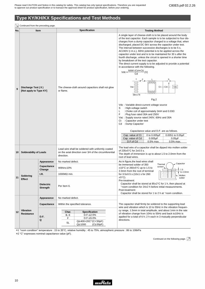
A single layer of cheese-cloth is to be placed around the bodyof the test capacitor. Each sample is to be subjected to four dis-charges from a dump capacitor charged to a voltage that, whendischarged, placed DC 5kV across the capacitor under test.The interval between successive discharges is to be 5 s.AC240V (r.m.s.), 60Hz potential is to be applied across thecapacitor under test and is to be maintained for 30 s after thefourth discharge, unless the circuit is opened in a shorter timeby breakdown of the test capacitor.The direct current supply is to be adjusted to provide a potentialin accordance with the following.
Vdc : Variable direct-current voltage sourceS : High-voltage switchL : Choke coil of approximately 3mH and 0.03ΩF : Plug fuse rated 30A and 250VVac : Supply source rated 240V, 60Hz and 30ACt : Capacitor under testCd : Dump Capacitor
Continued from the preceding page.
Continued on the following page.
Discharge Test ( II )[Not apply to Type KY]
*1 "room condition" temperature : 15 to 35°C, relative humidity : 45 to 75%, atmospheric pressure : 86 to 106kPa*2 "C" expresses nominal capacitance value (pF).
The cheese-cloth around capacitors shall not glowor flame.
10
The lead wire of a capacitor shall be dipped into molten solderof 235±5°C for 2±0.5 s.The depth of immersion is up to about 1.5 to 2.0mm from theroot of lead wires.
Solderability of LeadsLead wire shall be soldered with uniformly coatedon the axial direction over 3/4 of the circumferentialdirection.
11
As in figure,the lead wires shall be immersed solder of 350±10°C or 260±5°C up to 1.5 to 2.0mm from the root of terminal for 3.5±0.5 s (10±1 s for 260±5°C).Pre-treatment:
Capacitor shall be stored at 85±2°C for 1 h, then placed at∗ 1room condition for 24±2 h before initial measurements.
Post-treatment:Capacitor shall be stored for 1 to 2 h at ∗ 1room condition.
Soldering Effect
VibrationResistance
Appearance No marked defect.
CapacitanceChange
Within±10%
I.R. 1000MΩ min.
DielectricStrength
Per Item 6.
Specifications and Test Methods
Vdc=5000 (CdWCt)
(V)Cd
T
SB1179
F L S
Vac Ct Cd Vdc
Fig.2
Cap. value of CtCap. value of Cd
D.F.of Cd
0 to 0.005µF0.005µF
0.5% max.
0.0051 to 0.05µF0.05µF
0.5% max.
Capacitance value and D.F. are as follows.
12
The capacitor shall firmly be soldered to the supporting leadwire and vibration which is 10 to 55Hz in the vibration frequen-cy range, 1.5mm in total amplitude, and about 1min in the rateof vibration change from 10Hz to 55Hz and back to10Hz isapplied for a total of 6 h; 2 h each in 3 mutually perpendiculardirections.
Appearance No marked defect.
Capacitance Within the specified tolerance.
D.F.Q
Thermalscreen
Capacitor
1.5to 2.0mm
Moltensolder
Char.B, E
F
SL
D.F.V2.5%D.F.V5.0%
QU400+20C*2(CF30pF)QU1000 (CU30pF)
Specification
Type KY/KH/KX Specifications and Test Methods
10
3
Please read CAUTION and Notice in this catalog for safety. This catalog has only typical specifications. Therefore you are requestedto approve our product specification or to transact the approval sheet for product specification, before your ordering.
C80E5.pdf 02.2.26
Specifications and Test Methods
No. Item Specification Testing Method
Continued from the preceding page.
Continued on the following page.
No marked defect.
Humidity(Under Steady State)
Appearance
13
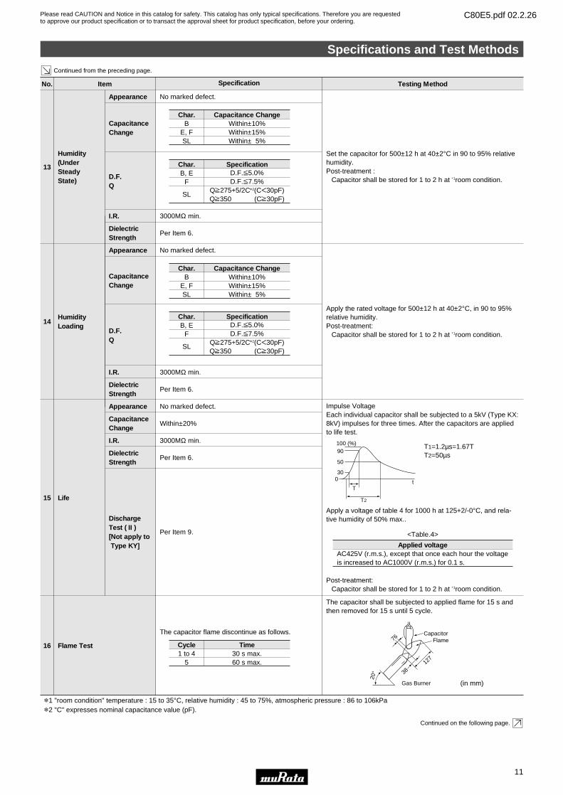
Set the capacitor for 500±12 h at 40±2°C in 90 to 95% relativehumidity.Post-treatment :
Capacitor shall be stored for 1 to 2 h at ∗ 1room condition.
CapacitanceChange
D.F.Q
I.R. 3000MΩ min.
DielectricStrength
Per Item 6.
Char.B
E, FSL
Within±10%Within±15%Within± 5%
Capacitance Change
Char.B, E
F
SL
D.F.V5.0%D.F.V7.5%
QU275+5/2C*2(CF30pF)QU350 (CU30pF)
Specification
No marked defect.
HumidityLoading
Appearance
14
Apply the rated voltage for 500±12 h at 40±2°C, in 90 to 95%relative humidity.Post-treatment:
Capacitor shall be stored for 1 to 2 h at ∗ 1room condition.
CapacitanceChange
D.F.Q
I.R. 3000MΩ min.
DielectricStrength
Per Item 6.
Char.B
E, FSL
Within±10%Within±15%Within± 5%
Capacitance Change
Char.B, E
F
SL
D.F.V5.0%D.F.V7.5%
QU275+5/2C*2(CF30pF)QU350 (CU30pF)
Specification
No marked defect.
Life
Appearance
15
Impulse VoltageEach individual capacitor shall be subjected to a 5kV (Type KX:8kV) impulses for three times. After the capacitors are appliedto life test.
Apply a voltage of table 4 for 1000 h at 125+2/-0°C, and rela-tive humidity of 50% max..
Post-treatment:Capacitor shall be stored for 1 to 2 h at ∗ 1room condition.
CapacitanceChange
Within±20%
I.R. 3000MΩ min.
DielectricStrength
Per Item 6.
DischargeTest ( II )[Not apply to Type KY]
Per Item 9.
The capacitor flame discontinue as follows.
Flame Test16
The capacitor shall be subjected to applied flame for 15 s andthen removed for 15 s until 5 cycle.
T1=1.2µs=1.67TT2=50µs
300
T
T2
50
90100 (%)
t
AC425V (r.m.s.), except that once each hour the voltageis increased to AC1000V (r.m.s.) for 0.1 s.
Applied voltage
<Table.4>
(in mm)
CapacitorFlame76
20° 38
127
Gas Burner
Cycle1 to 4
530 s max.60 s max.
Time
*1 "room condition" temperature : 15 to 35°C, relative humidity : 45 to 75%, atmospheric pressure : 86 to 106kPa*2 "C" expresses nominal capacitance value (pF).
Specifications and Test Methods
11
3

Please read CAUTION and Notice in this catalog for safety. This catalog has only typical specifications. Therefore you are requestedto approve our product specification or to transact the approval sheet for product specification, before your ordering.
C80E5.pdf 02.2.26
Specifications and Test Methods
No. Item Specification Testing Method
The cheese-cloth shall not be on fire.Active Flammability18
The capacitor shall be individually wrapped in at least one butmore than two complete layers of cheese-cloth.The capacitorshall be subjected to 20 discharges. The interval between suc-cessive discharges shall be 5 s. The UAC shall be maintainedfor 2 min after the last discharge.
C1,2 : 1µF±10% L1 to 4 : 1.5mH±20%C3 : 0.033µF±5% 10kV : 16A Rod core chokeCt : 3µF±5% 10kV R : 100Ω±2%Cx : Capacitor under test UAC : UR±5%F : Fuse, Rated 10A UR : Rated Voltage
Ut : Voltage applied to Ct
Continued from the preceding page.
The burning time shall not be exceeded the time 30 s.The tissue paper shall not ignite.
Passive Flammability19
The capacitor under test shall be held in the flame in the posi-tion which best promotes burning. Each specimen shall only beexposed once to the flame. Time of exposure to flame: 30 s.
Length of flame : 12±1mmGas burner : Length 35mm min.Inside Dia. : 0.5±0.1mmOutside Dia. : 0.9mm max.Gas : Butane gas Purity 95% min.
UtCtCxC3C2
L1
L3
L2 R
L4
C1
S2Tr
S1
UAC
F
Oscilloscope
Ux
5kV
time
Abo
ut 8
mm
200T
5mm
Test specimen
TissueAbout 10mm thick board
45°
Lead wire shall not cut off. Capacitor shall not bebroken.
Robustness of terminations
Tensile
Bending
17
As a figure, fix the body of capacitor, apply a tensile weight gradually to each lead wire in the radial direction of capacitor up to 10N and keep it for 10±1 s.
Each lead wire shall be subjected to 5N weight and then a 90°bend, at the point of egress, in one direction, return to originalposition, and then a 90° bend in the opposite direction at therate of one bend in 2 to 3 s.
W
Continued on the following page.
Type KY/KH/KX Specifications and Test Methods
12
3
Please read CAUTION and Notice in this catalog for safety. This catalog has only typical specifications. Therefore you are requestedto approve our product specification or to transact the approval sheet for product specification, before your ordering.
C80E5.pdf 02.2.26
Specifications and Test Methods
No. Item Specification Testing Method
Continued from the preceding page.
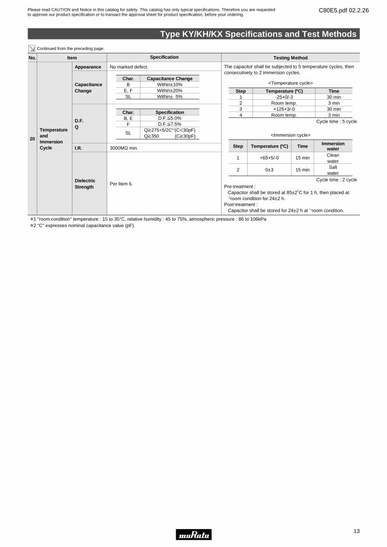
No marked defect.Appearance The capacitor shall be subjected to 5 temperature cycles, thenconsecutively to 2 immersion cycles.
Pre-treatment : Capacitor shall be stored at 85±2˚C for 1 h, then placed at∗ 1room condition for 24±2 h.
Post-treatment : Capacitor shall be stored for 24±2 h at ∗ 1room condition.
CapacitanceChange Step
1234
-25+0/-3Room temp.+125+3/-0
Room temp.
30 min3 min
30 min3 min
Temperature (ºC) Time
<Temperature cycle>
Step
1
2
+65+5/-0
0±3
15 min
15 min
Temperature (ºC) Time
CleanwaterSalt
water
Immersionwater
<Immersion cycle>
Cycle time : 5 cycle
Cycle time : 2 cycle
*1 "room condition" temperature : 15 to 35°C, relative humidity : 45 to 75%, atmospheric pressure : 86 to 106kPa*2 "C" expresses nominal capacitance value (pF).
TemperatureandImmersionCycle
20
D.F.Q
I.R. 3000MΩ min.
DielectricStrength
Per Item 6.
Char.B
E, FSL
Within±10%Within±20%Within± 5%
Capacitance Change
Char.B, E
F
SL
D.F.V5.0%D.F.V7.5%
QU275+5/2C*2(CF30pF)QU350 (CU30pF)
Specification
Type KY/KH/KX Specifications and Test Methods
13
3
Please read CAUTION and Notice in this catalog for safety. This catalog has only typical specifications. Therefore you are requestedto approve our product specification or to transact the approval sheet for product specification, before your ordering.
C80E5.pdf 02.2.26
14
4
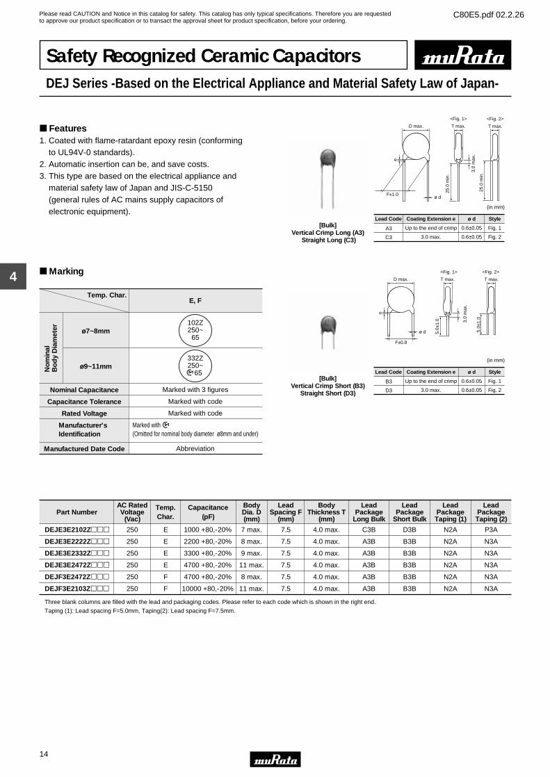
Safety Recognized Ceramic CapacitorsDEJ Series -Based on the Electrical Appliance and Material Safety Law of Japan-
Features1. Coated with flame-ratardant epoxy resin (conforming to UL94V-0 standards).2. Automatic insertion can be, and save costs.3. This type are based on the electrical appliance and material safety law of Japan and JIS-C-5150 (general rules of AC mains supply capacitors of electronic equipment).
Lead Code Coating Extension e
A3
C3
Up to the end of crimp
3.0 max.
(in mm)
ø d
0.6±0.05
0.6±0.05
Style
Fig. 1
Fig. 2
D max. T max.T max.
<Fig. 1> <Fig. 2>
3.0
max
.
25.0
min
.
e
ø d
25.0
min
.
F±1.0
[Bulk]Vertical Crimp Long (A3)
Straight Long (C3)
D max. T max.T max.
<Fig. 1> <Fig. 2>
3.0
max
.
5.0±
1.0
F±0.8
e
ø d 5.0±
1.0
Lead Code Coating Extension e
B3
D3
Up to the end of crimp
3.0 max.
(in mm)
ø d
0.6±0.05
0.6±0.05
Style
Fig. 1
Fig. 2
[Bulk]Vertical Crimp Short (B3)
Straight Short (D3)
Marking
Temp. Char.
No
min
alB
od
y D
iam
eter
Manufactured Date Code Abbreviation
E, F
Manufacturer'sIdentification
Rated Voltage Marked with code
Capacitance Tolerance Marked with code
Nominal Capacitance
ø9~11mm
ø7~8mm
Marked with 3 figures
102Z250~
65
Marked with (Omitted for nominal body diameter ø8mm and under)
332Z250~ 65
Part NumberAC RatedVoltage
(Vac)
Temp.Char.
Capacitance(pF)
BodyDia. D(mm)
LeadSpacing F
(mm)
BodyThickness T
(mm)
LeadPackage
Long Bulk
LeadPackage
Short Bulk
LeadPackageTaping (1)
LeadPackageTaping (2)
DEJE3E2102Zppp 250 E 1000 +80,-20% 7 max. 7.5 4.0 max. C3B D3B N2A P3A
DEJE3E2222Zppp 250 E 2200 +80,-20% 8 max. 7.5 4.0 max. A3B B3B N2A N3A
DEJE3E2332Zppp 250 E 3300 +80,-20% 9 max. 7.5 4.0 max. A3B B3B N2A N3A
DEJE3E2472Zppp 250 E 4700 +80,-20% 11 max. 7.5 4.0 max. A3B B3B N2A N3A
DEJF3E2472Zppp 250 F 4700 +80,-20% 8 max. 7.5 4.0 max. A3B B3B N2A N3A
DEJF3E2103Zppp 250 F 10000 +80,-20% 11 max. 7.5 4.0 max. A3B B3B N2A N3A
Three blank columns are filled with the lead and packaging codes. Please refer to each code which is shown in the right end.
Taping (1): Lead spacing F=5.0mm, Taping(2): Lead spacing F=7.5mm.
Please read CAUTION and Notice in this catalog for safety. This catalog has only typical specifications. Therefore you are requestedto approve our product specification or to transact the approval sheet for product specification, before your ordering.
C80E5.pdf 02.2.26
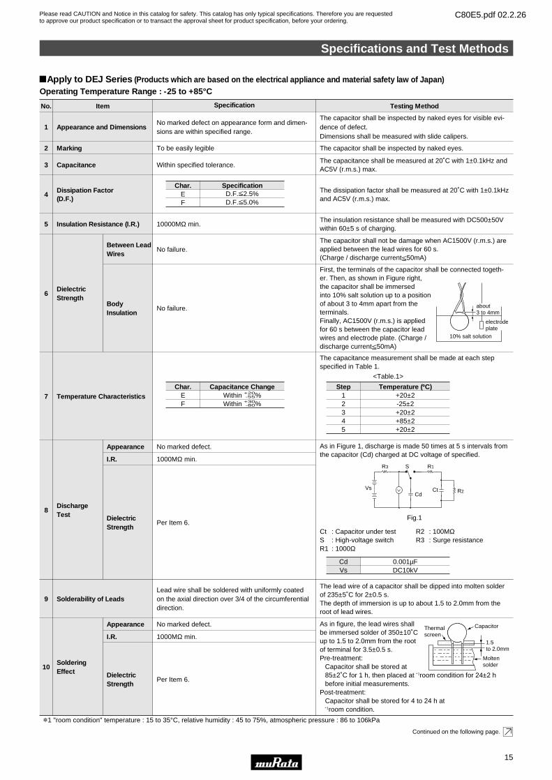
No. Item Specification Testing Method
To be easily legible
10000MΩ min.
No marked defect on appearance form and dimen-sions are within specified range.
Appearance and Dimensions
Marking
Insulation Resistance (I.R.)
1
2
5The insulation resistance shall be measured with DC500±50Vwithin 60±5 s of charging.
The capacitor shall be inspected by naked eyes.
The capacitor shall be inspected by naked eyes for visible evi-dence of defect.Dimensions shall be measured with slide calipers.
Within specified tolerance.Capacitance3The capacitance shall be measured at 20˚C with 1±0.1kHz andAC5V (r.m.s.) max.
Dissipation Factor(D.F.)
4The dissipation factor shall be measured at 20˚C with 1±0.1kHzand AC5V (r.m.s.) max.
No failure.
Dielectric Strength
Between LeadWires
6
The capacitor shall not be damage when AC1500V (r.m.s.) areapplied between the lead wires for 60 s.(Charge / discharge currentV50mA)
No failure.BodyInsulation
First, the terminals of the capacitor shall be connected togeth-er. Then, as shown in Figure right, the capacitor shall be immersed into 10% salt solution up to a position of about 3 to 4mm apart from the terminals.Finally, AC1500V (r.m.s.) is applied for 60 s between the capacitor lead wires and electrode plate. (Charge / discharge currentV50mA)
Temperature Characteristics7
The capacitance measurement shall be made at each stepspecified in Table 1.
No marked defect.
1000MΩ min.
Per Item 6.
Per Item 6.
Discharge Test
Appearance
I.R.
DielectricStrength
8
As in Figure 1, discharge is made 50 times at 5 s intervals fromthe capacitor (Cd) charged at DC voltage of specified.
Ct : Capacitor under test R2 : 100MΩS : High-voltage switch R3 : Surge resistanceR1 : 1000Ω
Lead wire shall be soldered with uniformly coatedon the axial direction over 3/4 of the circumferentialdirection.
Solderability of Leads9
The lead wire of a capacitor shall be dipped into molten solderof 235±5˚C for 2±0.5 s.The depth of immersion is up to about 1.5 to 2.0mm from theroot of lead wires.
SolderingEffect
Appearance
I.R.
DielectricStrength
10
As in figure, the lead wires shall be immersed solder of 350±10˚C up to 1.5 to 2.0mm from the root of terminal for 3.5±0.5 s.Pre-treatment:
Capacitor shall be stored at 85±2˚C for 1 h, then placed at ∗ 1room condition for 24±2 hbefore initial measurements.
Post-treatment:Capacitor shall be stored for 4 to 24 h at ∗ 1room condition.
No marked defect.
1000MΩ min.
Continued on the following page.
Char.EF
D.F.V2.5%D.F.V5.0%
Specification
Char.EF
Within +20-55%
Within +30-80%
Capacitance Change Step12345
+20±2-25±2+20±2+85±2+20±2
Temperature (ºC)
about3 to 4mm
electrodeplate
10% salt solution
Vs
R3 R1
R2
S
CdCt
<Table.1>
CdVs
0.001µFDC10kV
Fig.1
!Apply to DEJ Series (Products which are based on the electrical appliance and material safety law of Japan)Operating Temperature Range : -25 to +85°C
Thermalscreen
Capacitor
1.5to 2.0mm
Moltensolder
*1 "room condition" temperature : 15 to 35°C, relative humidity : 45 to 75%, atmospheric pressure : 86 to 106kPa
Specifications and Test Methods
15
4
Please read CAUTION and Notice in this catalog for safety. This catalog has only typical specifications. Therefore you are requestedto approve our product specification or to transact the approval sheet for product specification, before your ordering.
C80E5.pdf 02.2.26
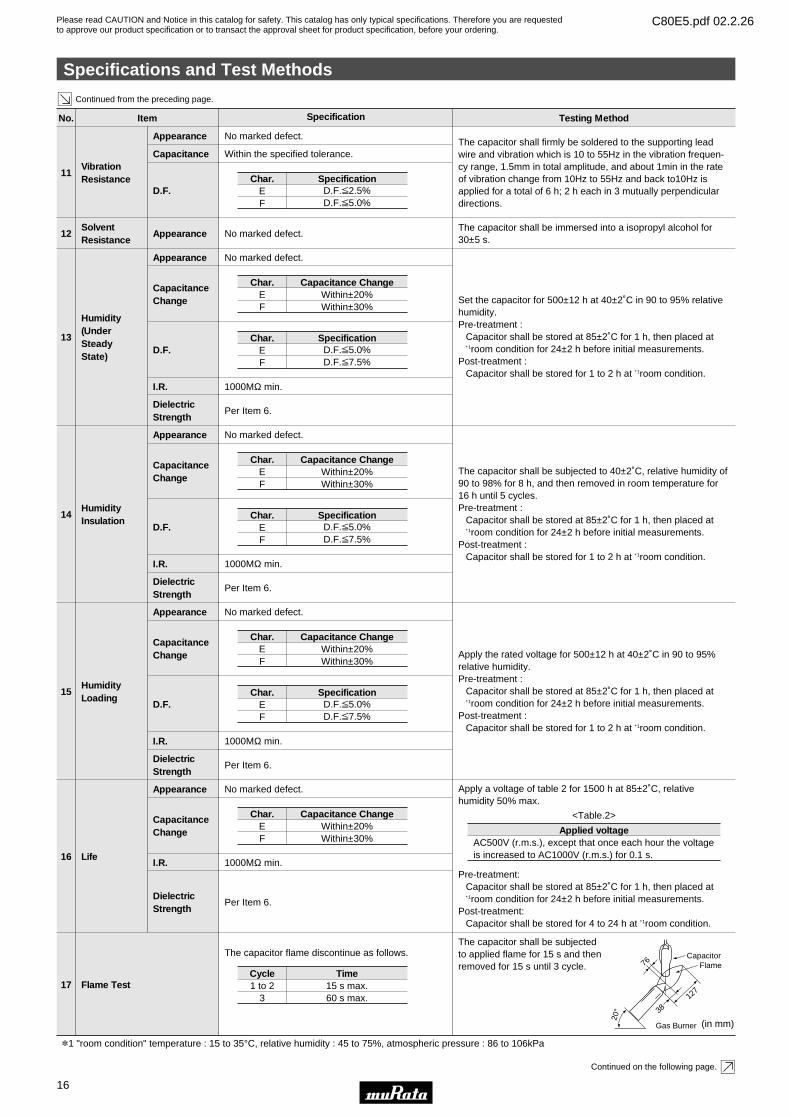
No. Item Specification Testing Method
11
The capacitor shall firmly be soldered to the supporting leadwire and vibration which is 10 to 55Hz in the vibration frequen-cy range, 1.5mm in total amplitude, and about 1min in the rateof vibration change from 10Hz to 55Hz and back to10Hz isapplied for a total of 6 h; 2 h each in 3 mutually perpendiculardirections.
Continued from the preceding page.
Continued on the following page.
VibrationResistance
Appearance
Capacitance
D.F.
No marked defect.
12The capacitor shall be immersed into a isopropyl alcohol for30±5 s.
Solvent Resistance
Appearance No marked defect.
Within the specified tolerance.
Char.EF
D.F.V2.5%D.F.V5.0%
Specification
13
Set the capacitor for 500±12 h at 40±2˚C in 90 to 95% relativehumidity.Pre-treatment :
Capacitor shall be stored at 85±2˚C for 1 h, then placed at∗ 1room condition for 24±2 h before initial measurements.
Post-treatment : Capacitor shall be stored for 1 to 2 h at ∗ 1room condition.
Humidity(Under Steady State)
Appearance No marked defect.
CapacitanceChange
*1 "room condition" temperature : 15 to 35°C, relative humidity : 45 to 75%, atmospheric pressure : 86 to 106kPa
D.F.
I.R. 1000MΩ min.
DielectricStrength
Per Item 6.
Char.EF
Within±20%Within±30%
Capacitance Change
Char.EF
D.F.V5.0%D.F.V7.5%
Specification
14
The capacitor shall be subjected to 40±2˚C, relative humidity of90 to 98% for 8 h, and then removed in room temperature for16 h until 5 cycles.Pre-treatment :
Capacitor shall be stored at 85±2˚C for 1 h, then placed at∗ 1room condition for 24±2 h before initial measurements.
Post-treatment : Capacitor shall be stored for 1 to 2 h at ∗ 1room condition.
HumidityInsulation
Appearance No marked defect.
CapacitanceChange
D.F.
I.R. 1000MΩ min.
DielectricStrength
Per Item 6.
Char.EF
Within±20%Within±30%
Capacitance Change
Char.EF
D.F.V5.0%D.F.V7.5%
Specification
15
Apply the rated voltage for 500±12 h at 40±2˚C in 90 to 95%relative humidity.Pre-treatment :
Capacitor shall be stored at 85±2˚C for 1 h, then placed at∗ 1room condition for 24±2 h before initial measurements.
Post-treatment : Capacitor shall be stored for 1 to 2 h at ∗ 1room condition.
HumidityLoading
Appearance No marked defect.
CapacitanceChange
D.F.
I.R. 1000MΩ min.
DielectricStrength
Per Item 6.
Char.EF
Within±20%Within±30%
Capacitance Change
Char.EF
D.F.V5.0%D.F.V7.5%
Specification
16
Apply a voltage of table 2 for 1500 h at 85±2˚C, relative humidity 50% max.
Pre-treatment:Capacitor shall be stored at 85±2˚C for 1 h, then placed at∗ 1room condition for 24±2 h before initial measurements.
Post-treatment:Capacitor shall be stored for 4 to 24 h at ∗ 1room condition.
Life
Appearance No marked defect.
CapacitanceChange
17
The capacitor shall be subjected to applied flame for 15 s and then removed for 15 s until 3 cycle.
Flame Test
The capacitor flame discontinue as follows.
I.R. 1000MΩ min.
DielectricStrength
Per Item 6.
Char.EF
Within±20%Within±30%
Capacitance Change
Cycle1 to 2
315 s max.60 s max.
Time
AC500V (r.m.s.), except that once each hour the voltageis increased to AC1000V (r.m.s.) for 0.1 s.
Applied voltage
<Table.2>
CapacitorFlame76
20° 38
127
Gas Burner (in mm)
Specifications and Test Methods
16
4
Please read CAUTION and Notice in this catalog for safety. This catalog has only typical specifications. Therefore you are requestedto approve our product specification or to transact the approval sheet for product specification, before your ordering.
C80E5.pdf 02.2.26
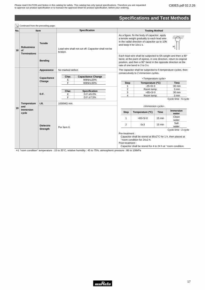
No. Item Specification Testing Method
Lead wire shall not cut off. Capacitor shall not bebroken.
Robustness of Terminations
Tensile
Bending
18
As a figure, fix the body of capacitor, apply a tensile weight gradually to each lead wire in the radial direction of capacitor up to 10N and keep it for 10±1 s.
Each lead wire shall be subjected to 5N weight and then a 90°bend, at the point of egress, in one direction, return to originalposition, and then a 90° bend in the opposite direction at therate of one bend in 2 to 3 s.
Continued from the preceding page.
No marked defect.
TemperatureandImmersioncycle
Appearance
19
The capacitor shall be subjected to 5 temperature cycles, thenconsecutively to 2 immersion cycles.
Pre-treatment : Capacitor shall be stored at 85±2˚C for 1 h, then placed at∗ 1room condition for 24±2 h.
Post-treatment : Capacitor shall be stored for 4 to 24 h at ∗ 1room condition.
W
CapacitanceChange
D.F.
I.R. 1000MΩ min.
DielectricStrength
Per Item 6.
Char.EF
Within±20%Within±30%
Capacitance Change
Char.EF
D.F.V5.0%D.F.V7.5%
Specification
Step1234
-25+0/-3Room temp.
+85+3/-0Room temp.
30 min3 min
30 min3 min
Temperature (ºC) Time
<Temperature cycle>
Step
1
2
+65+5/-0
0±3
15 min
15 min
Temperature (ºC) Time
CleanwaterSalt
water
Immersionwater
<Immersion cycle>
Cycle time : 5 cycle
Cycle time : 2 cycle
*1 "room condition" temperature : 15 to 35°C, relative humidity : 45 to 75%, atmospheric pressure : 86 to 106kPa
Specifications and Test Methods
17
4
Please read CAUTION and Notice in this catalog for safety. This catalog has only typical specifications. Therefore you are requestedto approve our product specification or to transact the approval sheet for product specification, before your ordering.
C80E5.pdf 02.2.26
Characteristics Data (Typical Example)
18
4
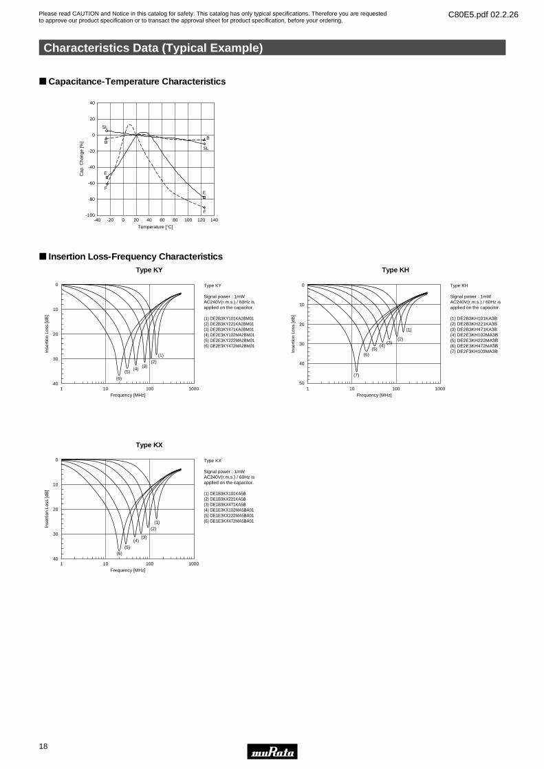
Capacitance-Temperature Characteristics
BB
E
Temperature [°C]
-40
40
20
0
-20
-40
-60
-80
-100-20 0 20 40 60 80 100 120 140
Cap
. Cha
nge
[%]
E
F
F
SL
SL
Insertion Loss-Frequency Characteristics Type KY
0
10
20
30
401 10 100 1000
Frequency [MHz]
Inse
rtio
n Lo
ss [d
B]
Type KY
Signal power : 1mWAC240V(r.m.s.) / 60Hz isapplied on the capacitor.
(1) DE2B3KY101KA2BM01(2) DE2B3KY221KA2BM01(3) DE2B3KY471KA2BM01(4) DE2E3KY102MA2BM01(5) DE2E3KY222MA2BM01(6) DE2E3KY472MA2BM01
(6)
(5)(4)
(3)(2)
(1)
Type KH
0
10
20
30
40
501 10 100 1000
Frequency [MHz]
Inse
rtio
n Lo
ss [d
B]
Type KH
Signal power : 1mWAC240V(r.m.s.) / 60Hz isapplied on the capacitor.
(1) DE2B3KH101KA3B(2) DE2B3KH221KA3B(3) DE2B3KH471KA3B(4) DE2E3KH102MA3B(5) DE2E3KH222MA3B(6) DE2E3KH472MA3B(7) DE2F3KH103MA3B
(7)
(6)(5)
(4)(3)
(2)
(1)
Type KX
0
10
20
30
401 10 100 1000
Frequency [MHz]
Inse
rtio
n Lo
ss [d
B]
Type KX
Signal power : 1mWAC240V(r.m.s.) / 60Hz isapplied on the capacitor.
(1) DE1B3KX101KA5B(2) DE1B3KX221KA5B(3) DE1B3KX471KA5B(4) DE1E3KX102MA5BA01(5) DE1E3KX222MA5BA01(6) DE1E3KX472MA5BA01
(6)(5)
(4)(3)
(2)(1)
Please read CAUTION and Notice in this catalog for safety. This catalog has only typical specifications. Therefore you are requestedto approve our product specification or to transact the approval sheet for product specification, before your ordering.
C80E5.pdf 02.2.26
Characteristics Data (Typical Example)
19
4
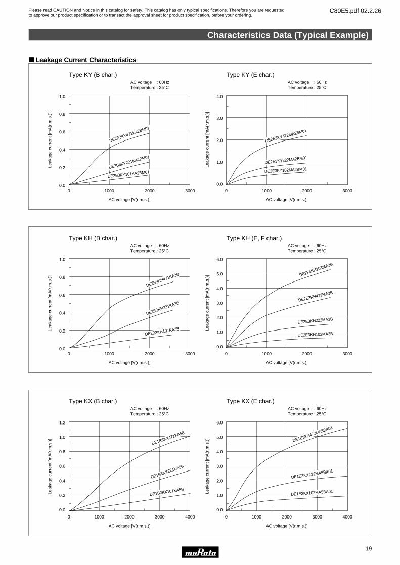
Leakage Current Characteristics
1.0 4.0
AC voltage : 60HzTemperature : 25°C
AC voltage : 60HzTemperature : 25°C
Type KY (B char.) Type KY (E char.)
3.0
2.0
1.0
0.0
0.8
0.6
0.4
0.2
0.00 1000 2000 3000 0 1000 2000 3000
AC voltage [V(r.m.s.)] AC voltage [V(r.m.s.)]
Leak
age
curr
ent [
mA
(r.m
.s.)
]
Leak
age
curr
ent [
mA
(r.m
.s.)
]
DE2B3KY471KA2BM01
DE2B3KY221KA2BM01
DE2B3KY101KA2BM01
DE2E3KY472MA2BM01
DE2E3KY222MA2BM01
DE2E3KY102MA2BM01
1.0 6.0
5.0
4.0
3.0
2.0
1.0
0.0
AC voltage : 60HzTemperature : 25°C
AC voltage : 60HzTemperature : 25°C
Type KH (B char.) Type KH (E, F char.)
0.8
0.6
0.4
0.2
0.00 1000 2000 3000 0 1000 2000 3000
AC voltage [V(r.m.s.)] AC voltage [V(r.m.s.)]
Leak
age
curr
ent [
mA
(r.m
.s.)
]
Leak
age
curr
ent [
mA
(r.m
.s.)
]
DE2B3KH471KA3B
DE2B3KH221KA3B
DE2B3KH101KA3B
DE2F3KH103MA3B
DE2E3KH472MA3B
DE2E3KH222MA3B
DE2E3KH102MA3B
6.0
5.0
4.0
3.0
2.0
1.0
0.0
0 1000 2000 3000 4000
1.2
1.0
0.8
0.6
0.4
0.2
0.0
0 1000 2000 3000 4000
AC voltage : 60HzTemperature : 25°C
AC voltage : 60HzTemperature : 25°C
Type KX (B char.) Type KX (E char.)
AC voltage [V(r.m.s.)] AC voltage [V(r.m.s.)]
Leak
age
curr
ent [
mA
(r.m
.s.)
]
Leak
age
curr
ent [
mA
(r.m
.s.)
]
DE1B3KX471KA5B
DE1B3KX221KA5B
DE1B3KX101KA5B
DE1E3KX472MA5BA01
DE1E3KX222MA5BA01
DE1E3KX102MA5BA01
Please read CAUTION and Notice in this catalog for safety. This catalog has only typical specifications. Therefore you are requestedto approve our product specification or to transact the approval sheet for product specification, before your ordering.
C80E5.pdf 02.2.26
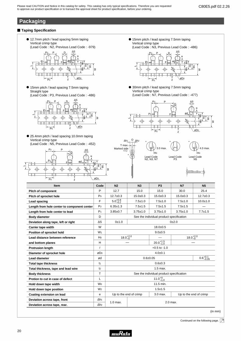
Item
Pitch of component
Pitch of sprocket hole
Lead spacing
Length from hole center to component center
Length from hole center to lead
Body diameter
Deviation along tape, left or right
Carrier tape width
Position of sprocket hold
Lead distance between reference
and bottom planes
Protrusion length
Diameter of sprocket hole
Lead diameter
Total tape thickness
Total thickness, tape and lead wire
Body thickness
Protion to cut in case of defect
Hold down tape width
Hold down tape position
Coating extension on lead
Deviation across tape, front
Deviation across tape, rear.
P
P0
F
P2
P1
D
∆S
W
W1
H0
H
r
øD0
ød
t1
t2
T
L
W0
W2
e
∆h1
∆h2
12.7
12.7±0.3
5.0
6.35±1.3
3.85±0.7
15.0
15.0±0.3
7.5±1.0
7.5±1.5
3.75±1.0
15.0
15.0±0.3
7.5±1.0
7.5±1.5
3.75±1.0
0±2.00±1.0
30.0
15.0±0.3
7.5±1.0
7.5±1.5
3.75±1.0
See the individual product specification
18.0±0.5
9.0±0.5
+0.5 to -1.0
4.0±0.1
0.6±0.3
1.5 max.
See the individual product specification
11.0
11.5 min.
1.5±1.5
3.0 max.
20.0
25.4
12.7±0.3
10.0±1.0
—
7.7±1.5
2.0 max.1.0 max.
(in mm)
N2 N3 P3 N7 N5Code
+0.8–0.2
+1.5–1.0
18.0
–
–+2.0–0 18.0
–
+2.0–0
+0–1.0
Taping Specification
12.7mm pitch / lead spacing 5mm taping Vertical crimp type (Lead Code : N2, Previous Lead Code : -979)
15mm pitch / lead spacing 7.5mm taping Vertical crimp type (Lead Code : N3, Previous Lead Code : -486)
0.6±0.05
30mm pitch / lead spacing 7.5mm taping Vertical crimp type (Lead Code : N7, Previous Lead Code : -477)
25.4mm pitch / lead spacing 10.0mm taping Vertical crimp type (Lead Code : N5, Previous Lead Code : -452)
L
P1
P2
P0
PD
∆S
F ød
øD0R
W0 W
1
W
eW
2
H0
L
P1
P2
P0
P D ∆S
F ød
øD0R
W0 W
1
W H
0
e
W2
L
P1
P2
P0
P D ∆S
F ød
øD0R
W0
W2
W1
W
e
H0
15mm pitch / lead spacing 7.5mm taping Straight type (Lead Code : P3, Previous Lead Code : -486)
L
P1
P2
P0
P D ∆S
F ød
øD0R
W0
W2
W1
W
e
H
L
P1
P2
P0
PD
∆S
F ød
øD0R
W0 W
1
W
eW
2
H0
T max.
∆h1 ∆h2O∗
∗
Marked side
t2 t1
0.6 +0.1–0.05
Continued on the following page.
Up to the end of crimp Up to the end of crimp
∗
3.0 max.
Lead CodeN2, N3, N7
∗
4.0 max.
Lead CodeN5
Lead CodeP3
H0 H0
Packaging
20
4

Please read CAUTION and Notice in this catalog for safety. This catalog has only typical specifications. Therefore you are requestedto approve our product specification or to transact the approval sheet for product specification, before your ordering.
C80E5.pdf 02.2.26
Packaging Styles
[Bulk] 1,000 pcs.
[Taping]
“Minimum Quantity” means the numbers of units of each delivery or order.
The quantity should be an integral multiple of the “minimum quantity”.
(Please note that the actual delivery quantity in a package may change in case.)
TapingBulk
Polyethylene Bag Ammo Pack
Minimum Quantity (Order in Sets Only)
Minimum Order Quantity
Continued from the preceding page.
Lead Code Type KY
N2
N3, P3
N7
N5
1,000
–
–
–
Type KH
–
900
400
–
Type KX
–
–
–
500
DEJ Series
1,500
1,000
–
–
[Bulk] 3,000 pcs.
[Taping]
Lead Code Type KY
N2
N3, P3
N7
N5
3,000
–
–
–
Type KH
–
2,700
2,000
–
Type KX
–
–
–
2,000
DEJ Series
3,000
3,000
–
–
(pcs.)
(pcs.)
Packaging
21
4
Please read CAUTION and Notice in this catalog for safety. This catalog has only typical specifications. Therefore you are requestedto approve our product specification or to transact the approval sheet for product specification, before your ordering.
C80E5.pdf 02.2.26
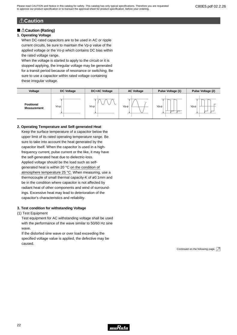
When DC-rated capacitors are to be used in AC or ripple current circuits, be sure to maintain the Vp-p value of the applied voltage or the Vo-p which contains DC bias within the rated voltage range. When the voltage is started to apply to the circuit or it is stopped applying, the irregular voltage may be generated for a transit period because of resonance or switching. Be sure to use a capacitor within rated voltage containing these irregular voltage.
Voltage
Positional Measurement
DC Voltage DC+AC Voltage AC Voltage Pulse Voltage (1) Pulse Voltage (2)
V0-p V0-p Vp-p Vp-p Vp-p
1. Operating Voltage
Keep the surface temperature of a capacitor below the upper limit of its rated operating temperature range. Be sure to take into account the heat generated by the capacitor itself. When the capacitor is used in a high-frequency current, pulse current or the like, it may have the self-generated heat due to dielectric-loss. Applied voltage should be the load such as self- generated heat is within 20 °C on the condition of atmosphere temperature 25 °C. When measuring, use a thermocouple of small thermal capacity-K of ø0.1mm and be in the condition where capacitor is not affected by radiant heat of other components and wind of surround-ings. Excessive heat may lead to deterioration of the capacitor's characteristics and reliability.
2. Operating Temperature and Self-generated Heat
Test equipment for AC withstanding voltage shall be used with the performance of the wave similar to 50/60 Hz sine wave.If the distorted sine wave or over load exceeding the specified voltage value is applied, the defective may be caused.
3. Test condition for withstanding Voltage(1) Test Equipment
Continued on the following page.
!Caution (Rating)
!Caution
22
4

Please read CAUTION and Notice in this catalog for safety. This catalog has only typical specifications. Therefore you are requestedto approve our product specification or to transact the approval sheet for product specification, before your ordering.
C80E5.pdf 02.2.26
Continued from the preceding page.
When the withstanding voltage is applied, capacitor's lead or terminal shall be firmly connected to the out-put of the withstanding voltage test equipment, and then the voltage shall be raised from near zero to the test voltage.If the test voltage without the raise from near zero voltage would be applied directly to capacitor, test voltage should be applied with the *zero cross. At the end of the test time, the test voltage shall be reduced to near zero, and then capacitor's lead or terminal shall be taken off the out-put of the withstanding voltage test equipment.If the test voltage without the raise from near zero voltage would be applied directly to capacitor, the surge voltage may arise, and therefore, the defective may be caused.
*ZERO CROSS is the point where voltage sine wave pass 0V. - See the right figure -
(2) Voltage Applied Method
0V
zero cross
Voltage sine wave
When capacitor would be broken, failure may result in a short circuit. Be sure to provide an appropriate fail-safe function like a fuse on your product if failure would follow an electric shock, fire or fume.
Failure to follow the above cautions may result, worst case, in a short circuit and cause fuming or partial dispersion when the product is used.
4. Fail-Safe
!Caution
23
4

Please read CAUTION and Notice in this catalog for safety. This catalog has only typical specifications. Therefore you are requestedto approve our product specification or to transact the approval sheet for product specification, before your ordering.
C80E5.pdf 02.2.26
!Caution
24
4
!Caution (Storage and operating condition)Operating and storage environment The insulating coating of capacitors does not form a perfect seal; therefore, do not use or store capacitors in a corrosive atmosphere, especially where chloride gas, sulfide gas, acid, alkali, salt or the like are present. And avoid exposure to moisture. Before cleaning, bonding, or molding this product, verify that these processes do not affect product quality by testing the performance of a
cleaned, bonded or molded product in the intended equipment. Store the capacitors where the temperature and relative humidity do not exceed -10 to 40 degrees centigrade and 15 to 85 %. Use capacitors within 6 months."Failure to follow the above cautions may result, worst case, in a short circuit and cause fuming or partial dispersion when the product is used."
!Caution (Soldering and Mounting)1. Vibration and impact Do not expose a capacitor or its leads to excessive shock or vibration during use.2. Soldering When soldering this product to a PCB/PWB, do not exceed the solder heat resistance specification of the capacitor. Subjecting this product to excessive heating could melt the internal junction solder and may result in thermal shocks that can crack the ceramic element."Failure to follow the above cautions may result, worst case, in a short circuit and cause fuming or partial dispersion when the product is used."
!Caution (Handling)Vibration and impact Do not expose a capacitor or its leads to excessive shock or vibration during use."Failure to follow the above cautions may result, worst case, in a short circuit and cause fuming or partial dispersion when the product is used."

Please read CAUTION and Notice in this catalog for safety. This catalog has only typical specifications. Therefore you are requestedto approve our product specification or to transact the approval sheet for product specification, before your ordering.
C80E5.pdf 02.2.26
Notice
25
4
Notice (Soldering and Mounting)Cleaning(ultrasonic cleaning) To perform ultrasonic cleaning, observe the following conditions. Rinse bath capacity : Output of 20 watts per liter or less. Rinsing time : 5 min maximum. Do not vibrate the PCB/PWB directly. Excessive ultrasonic cleaning may lead to fatigue destruction of the lead wires.
Notice (Rating)Capacitance change of capacitors 1. Class 1 capacitors Capacitance might change a little depending on a surrounding temperature or an applied voltage. Please contact us if you use for the strict time constant circuit. 2. Class 2 and 3 capacitors Class 2 and 3 capacitors like temperature characteristic B, E and F have an aging
characteristic, whereby the capacitor continually decreases its capacitance slightly if the capacitor leaves for a long time. Moreover, capacitance might change greatly depending on a surrounding temperature or an applied voltage. So, it is not likely to be able to use for the time constant circuit. Please contact us if you need a detail information.
Please read CAUTION and Notice in this catalog for safety. This catalog has only typical specifications. Therefore you are requestedto approve our product specification or to transact the approval sheet for product specification, before your ordering.
C80E5.pdf 02.2.26
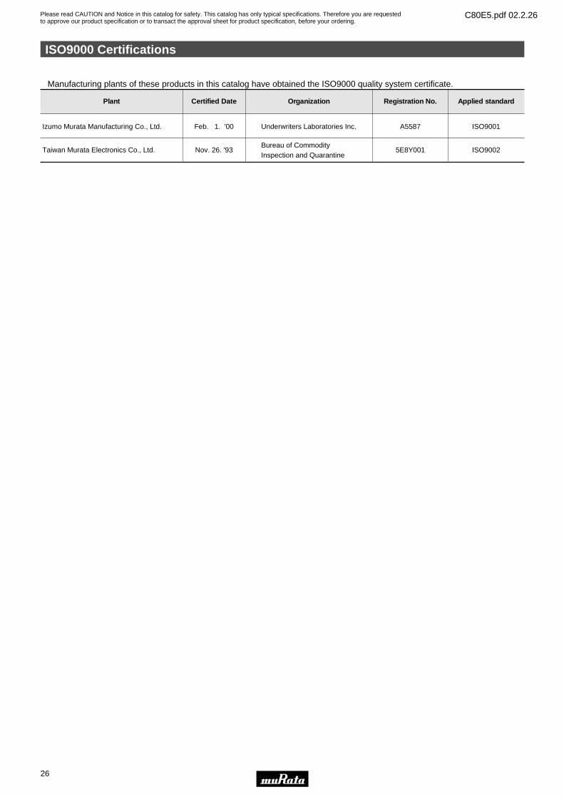
ISO9000 Certifications
26
4
Plant Certified Date
Feb. 1. '00
Organization Applied standard
ISO9001
Registration No.
A5587Izumo Murata Manufacturing Co., Ltd.
Taiwan Murata Electronics Co., Ltd. Nov. 26. '93
Underwriters Laboratories Inc.
Bureau of CommodityInspection and Quarantine
ISO90025E8Y001
Manufacturing plants of these products in this catalog have obtained the ISO9000 quality system certificate.
Head Office2-26-10, Tenjin Nagaokakyo-shi, Kyoto 617-8555, Japan Phone:81-75-951-9111
International Division3-29-12, Shibuya, Shibuya-ku, Tokyo 150-0002, Japan Phone:81-3-5469-6123 Fax:81-3-5469-6155 E-mail:[email protected]
http://www.murata.co.jp/products/
Please read CAUTION and Notice in this catalog for safety. This catalog has only typical specifications. Therefore you are requestedto approve our product specification or to transact the approval sheet for product specification, before your ordering.
C80E5.pdf 02.2.26
Note:1. Export Control
<For customers outside Japan>Murata products should not be used or sold for use in the development, production, stockpiling or utilization of any conventional weapons or mass-destructiveweapons (nuclear weapons, chemical or biological weapons, or missiles), or any other weapons.<For customers in Japan>For products which are controlled items subject to the “Foreign Exchange and Foreign Trade Law” of Japan, the export license specified by the law is requiredfor export.
2. Please contact our sales representatives or product engineers before using our products listed in this catalog for the applications listed below which requireespecially high reliability for the prevention of defects which might directly cause damage to the third party's life, body or property, or when intending to use oneof our products for other applications than specified in this catalog.q Aircraft equipmentw Aerospace equipmente Undersea equipmentr Power plant equipmentt Medical equipmenty Transportation equipment (vehicles, trains, ships, etc.)u Traffic signal equipmenti Disaster prevention / crime prevention equipmento Data-processing equipment!0 Application of similar complexity and/or reliability requirements to the applications listed in the above
3. Product specifications in this catalog are as of November 2001. They are subject to change or our products in it may be discontinued without advance notice.Please check with our sales representatives or product engineers before your ordering. If there are any questions, please contact our sales representatives orproduct engineers.
4. Please read CAUTION and Notice in this catalog for safety. This catalog has only typical specifications. Therefore you are requested to approve our productspecification or to transact the approval sheet for product specification, before your ordering.
5. Please note that unless otherwise specified, we shall assume no responsibility whatsoever for any conflict or dispute that may occur in connection with the effectof our and/or third party's intellectual property rights and other related rights in consideration of your using our products and/or information described orcontained in our catalogs. In this connection, no representation shall be made to the effect that any third parties are authorized to use the rights mentionedabove under licenses without our consent.
6. None of ozone depleting substances (ODS) under the Montreal Protocol is used in manufacturing process of us.