Safety Recall N18 / NHTSA 13V-103 Engine Starter Battery ... · Safety Recall N18 – Engine...
14
Copyright 2013, Chrysler Group LLC, All Rights Reserved March 2013 Dealer Service Instructions for: Safety Recall N18 / NHTSA 13V-103 Engine Starter Battery Positive Terminal 2013 (LC) Dodge Challenger NOTE: This recall applies only to the above vehicles equipped with a 3.6L engine (sales code ERB) built from December 03, 2012 through January 24, 2013 (MDH 120311 through 012413). The engine starter battery positive terminal on about 4,000 of the above vehicles could short to ground and cause an electrical fire. An electrical fire could occur at any time, regardless whether the vehicle is running or is in the key “OFF” position. An engine battery positive overlay wire harness must be installed. Models IMPORTANT: Some of the involved vehicles may be in dealer new vehicle inventory. Federal law requires you to complete this recall service on these vehicles before retail delivery. Dealers should also consider this requirement to apply to used vehicle inventory and should perform this recall on vehicles in for service. Involved vehicles can be determined by using the VIP inquiry process. Subject Repair
Transcript of Safety Recall N18 / NHTSA 13V-103 Engine Starter Battery ... · Safety Recall N18 – Engine...

Copyright 2013, Chrysler Group LLC, All Rights Reserved
March 2013 Dealer Service Instructions for:
Safety Recall N18 / NHTSA 13V-103
Engine Starter Battery Positive Terminal
2013 (LC) Dodge Challenger
NOTE: This recall applies only to the above vehicles equipped with a 3.6L engine
(sales code ERB) built from December 03, 2012 through January 24, 2013
(MDH 120311 through 012413).
The engine starter battery positive terminal on about 4,000 of the above vehicles
could short to ground and cause an electrical fire. An electrical fire could occur at
any time, regardless whether the vehicle is running or is in the key “OFF” position.
An engine battery positive overlay wire harness must be installed.
Models
IMPORTANT: Some of the involved vehicles may be in dealer new vehicle
inventory. Federal law requires you to complete this recall service on these
vehicles before retail delivery. Dealers should also consider this requirement to
apply to used vehicle inventory and should perform this recall on vehicles in for
service. Involved vehicles can be determined by using the VIP inquiry process.
Subject
Repair
Safety Recall N18 – Engine Starter Battery Positive Terminal Page 2
Dealers must minimize customer inconvenience by placing the owner in a loaner
vehicle.
Part Number Description
CAA0N181AA Engine Battery Positive (B+) Wire Overlay
Package
Each package contains the following components:
Quantity Description
1 Overlay Wire Harness, Engine Battery Positive
4 Clip, Push Pin Tie Straps
20 Strap, Plastic Tie
2 Rivet, Plastic Wheel Liner
The following special tools are required to perform this repair:
NPN wiTECH VCI Pod Kit
NPN Laptop Computer
NPN wiTECH Software
Alternate Transportation
Parts Information
Special Tools
Safety Recall N18 – Engine Starter Battery Positive Terminal Page 3
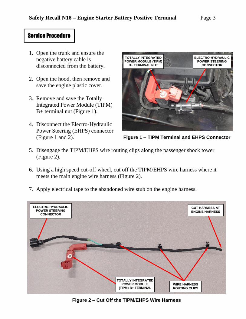
1. Open the trunk and ensure the
negative battery cable is
disconnected from the battery.
2. Open the hood, then remove and
save the engine plastic cover.
3. Remove and save the Totally
Integrated Power Module (TIPM)
B+ terminal nut (Figure 1).
4. Disconnect the Electro-Hydraulic
Power Steering (EHPS) connector
(Figure 1 and 2).
5. Disengage the TIPM/EHPS wire routing clips along the passenger shock tower
(Figure 2).
6. Using a high speed cut-off wheel, cut off the TIPM/EHPS wire harness where it
meets the main engine wire harness (Figure 2).
7. Apply electrical tape to the abandoned wire stub on the engine harness.
Service Procedure
Figure 1 – TIPM Terminal and EHPS Connector
Figure 2 – Cut Off the TIPM/EHPS Wire Harness
TOTALLY INTEGRATED POWER MODULE (TIPM)
B+ TERMINAL NUT
TOTALLY INTEGRATED POWER MODULE
(TIPM) B+ TERMINAL
ELECTRO-HYDRAULIC POWER STEERING
CONNECTOR
ELECTRO-HYDRAULIC POWER STEERING
CONNECTOR
WIRE HARNESS
ROUTING CLIPS
CUT HARNESS AT
ENGINE HARNESS
Safety Recall N18 – Engine Starter Battery Positive Terminal Page 4
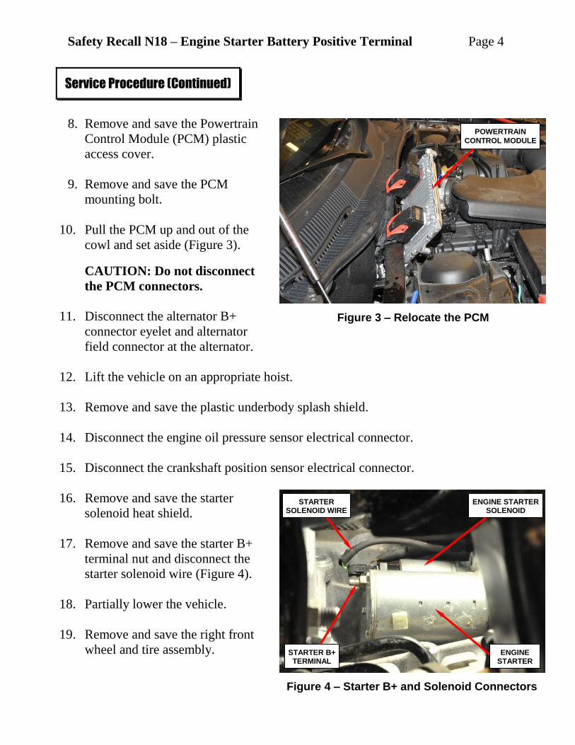
8. Remove and save the Powertrain
Control Module (PCM) plastic
access cover.
9. Remove and save the PCM
mounting bolt.
10. Pull the PCM up and out of the
cowl and set aside (Figure 3).
CAUTION: Do not disconnect
the PCM connectors.
11. Disconnect the alternator B+
connector eyelet and alternator
field connector at the alternator.
12. Lift the vehicle on an appropriate hoist.
13. Remove and save the plastic underbody splash shield.
14. Disconnect the engine oil pressure sensor electrical connector.
15. Disconnect the crankshaft position sensor electrical connector.
16. Remove and save the starter
solenoid heat shield.
17. Remove and save the starter B+
terminal nut and disconnect the
starter solenoid wire (Figure 4).
18. Partially lower the vehicle.
19. Remove and save the right front
wheel and tire assembly.
Service Procedure (Continued)
Figure 3 – Relocate the PCM
Figure 4 – Starter B+ and Solenoid Connectors
POWERTRAIN
CONTROL MODULE
ENGINE STARTER
ENGINE STARTER SOLENOID
STARTER B+ TERMINAL
STARTER SOLENOID WIRE

Safety Recall N18 – Engine Starter Battery Positive Terminal Page 5
20. Remove and save the right front
wheel opening plastic liner.
21. Disconnect the engine B+ wire
harness from the B+ stud on the
body that is located in the right
wheel opening (Figure 5).
22. Pull the engine B+ wire and grommet down to expose the wire above the
grommet (Figure 6).
23. Measure up from the grommet
approximately 6 inches (152 mm)
and place a mark on the engine
B+ wire (Figure 6).
Service Procedure (Continued)
Figure 5 – Engine B+ Wire Harness
Figure 6 – Engine B+ Wire and Grommet
ENGINE B+ WIRE
HARNESS
B+ BODY STUD
B+ WIRE GROMMET
WIRE HARNESS ROUTING CLIPS
ACCESS COVER
B+ WIRE
GROMMET
6” (152 MM)
PLACE MARK ON WIRE HARNESS

Safety Recall N18 – Engine Starter Battery Positive Terminal Page 6
24. Using a high speed cut-off wheel,
cut the B+ wire at the mark made
in Step 23 (Figure 7).
25. Apply electrical tape to the
abandoned wire stub on the
engine harness.
26. Lower the vehicle from the hoist.
27. Using a high speed cut-off wheel,
cut off the alternator B+ wire
approximately 8 inches from the
wire eyelet at the end of the
alternator B+ wire (Figure 8).
CAUTION: Use extreme caution
not to nick other underhood components when cutting the alternator B+ wire.
Service Procedure (Continued)
Figure 7 – Cut Off B+ Wire
Figure 8 – Cut Off Alternator Wiring End
ENGINE B+ WIRE
HARNESS HIGH SPEED
CUT-OFF WHEEL
8” (203 MM)
ALTERNATOR B+
WIRE EYELET
MARK AND CUT OFF ALTERNATOR B+ WIRE
WITH HIGH SPEED
CUT-OFF WHEEL
TERMINAL ACCESS COVER

Safety Recall N18 – Engine Starter Battery Positive Terminal Page 7
28. Apply electrical tape to the abandoned alternator B+ wire stub on the engine harness.
29. Raise the vehicle on the hoist.
30. Place a mark on the starter B+ wire approximately 2 inches from the end of the
wire (Figure 9).
31. Using a high speed cut-off wheel, cut the starter B+ wire at the mark made in
Step 30 (Figure 9).
CAUTION: Use extreme caution not to nick other components when
cutting the starter B+ wire.
32. Apply electrical tape to the abandoned wire stub on the engine harness.
33. Lower the vehicle from the hoist.
Service Procedure (Continued)
Figure 9 – Cut Off the Starter B+ Terminal from Engine Wire Harness
ENGINE STARTER SOLENOID WIRE
STARTER B+ TERMINAL
STARTER B+ WIRE
MARK AND CUT OFF STARTER B+ WIRE WITH HIGH SPEED CUT-OFF WHEEL

Safety Recall N18 – Engine Starter Battery Positive Terminal Page 8
34. At this point in the repair the components in Figure 10 have been cut from the
original engine wire harness.
NOTE: The new overlay wire harness has grey tape bands to indicate the
tie strap locations. Tie straps are to be placed at these locations to properly
secure the overlay harness to the original engine wire harness.
35. Starting at the rear of the right valve cover, carefully route the new engine battery
positive overlay wire harness starter B+ wire along the existing engine wiring harness.
CAUTION: Be sure to route the starter B+ wire behind the grey 24 way
connector wire harness at the rear of the left cylinder head
36. Raise the vehicle on the hoist.
37. Connect the new engine battery positive overlay wire harness starter B+ terminal
to the starter. Tighten the starter B+ terminal nut to 97 in. lbs. (11 N·m).
NOTE: Inspect all wire harness push pin tie strap retainers and replace as
required.
Service Procedure (Continued)
Figure 10 – Items Cut Off the Underhood Engine Harness
TIPM/EHPS
WIRE HARNESS
STARTER B+ WIRE
AND TERMINAL
ENGINE B+ WIRE HARNESS
ALTERNATOR B+
WIRE

Safety Recall N18 – Engine Starter Battery Positive Terminal Page 9
38. Connect the starter solenoid wire from the original engine wiring harness to the
starter solenoid.
39. Using one of the provided plastic tie straps, secure the new engine battery
positive overlay wire harness to the original engine wire harness (Figure 11).
CAUTION: Make sure the starter B+ wire cannot come in contact with
the exhaust pipe. Use tie straps as required to secure the starter B+ wire.
40. Install the starter solenoid heat shield.
41. Lower the vehicle from the hoist.
Service Procedure (Continued)
Figure 11 – Starter Wiring Routing
GREY 24-WAY
CONNECTOR
OVERLAY WIRE
HARNESS
OVERLAY HARNESS MUST ROUTE BEHIND
24-WAY WIRE
HARNESS
ORIGINAL STARTER
B+ WIRE HARNESS
PLASTIC TIE STRAP
VERIFY THAT THE STARTER WIRE HARNESS CANNOT MAKE
CONTACT WITH THE EXHAUST PIPE/FLANGE. INSTALL
ADDITIONAL TIE STRAPS IF REQUIRED.

Safety Recall N18 – Engine Starter Battery Positive Terminal Page 10
42. Route the engine battery positive overlay wire harness B+ cable into position
and through the body routing hole (Figure 12).
CAUTION: Be sure to seat the B+ wire grommet securely into the body
routing hole.
43. Remove and save the throttle body air inlet tube.
44. Route the Totally Integrated Power Module (TIPM) B+ terminal, the
Electro-Hydraulic Power Steering (EHPS) connector and related wiring into
position and engage routing clips.
Service Procedure (Continued)
Figure 12 – B+ Wire Grommet
PCM
B+ WIRE
GROMMET

Safety Recall N18 – Engine Starter Battery Positive Terminal Page 11
45. Install the engine battery positive
overlay wire harness TIPM B+
overlay terminal nut. Tighten the
nut to 106 in. lbs. (12 N·m)
(Figure 13).
46. Connect the engine battery
positive overlay wire harness
EHPS connector to the EHPS
body connector (Figure 13).
47. Route the engine battery positive
overlay wire harness for the
alternator into position and
connect the alternator B+
connector eyelet. Tighten the retaining nut to 97 in. lbs. (11 N·m).
48. Using plastic tie straps, secure the alternator overlay harness to the original
engine wiring harness at the grey tape bands.
49. Install the PCM into position and install the mounting bolt.
50. Install the PCM plastic access cover.
51. Lift the vehicle on the hoist.
52. Connect the crankshaft position sensor electrical connector to the sensor.
53. Connect the engine oil pressure sensor electrical connector to the sensor.
NOTE: Replace the push pin tie straps if required.
54. Connect the alternator field connector to the alternator.
55. Install the plastic underbody splash shield.
56. Partially lower the vehicle.
Service Procedure (Continued)
Figure 13 – Tighten TIPM Nut
TORQUE
WRENCH
TIPM NUT
EHPS CONNECTOR
Safety Recall N18 – Engine Starter Battery Positive Terminal Page 12
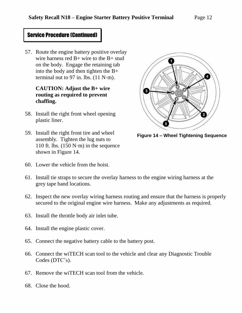
57. Route the engine battery positive overlay
wire harness red B+ wire to the B+ stud
on the body. Engage the retaining tab
into the body and then tighten the B+
terminal nut to 97 in. lbs. (11 N·m).
CAUTION: Adjust the B+ wire
routing as required to prevent
chaffing.
58. Install the right front wheel opening
plastic liner.
59. Install the right front tire and wheel
assembly. Tighten the lug nuts to
110 ft. lbs. (150 N·m) in the sequence
shown in Figure 14.
60. Lower the vehicle from the hoist.
61. Install tie straps to secure the overlay harness to the engine wiring harness at the
grey tape band locations.
62. Inspect the new overlay wiring harness routing and ensure that the harness is properly
secured to the original engine wire harness. Make any adjustments as required.
63. Install the throttle body air inlet tube.
64. Install the engine plastic cover.
65. Connect the negative battery cable to the battery post.
66. Connect the wiTECH scan tool to the vehicle and clear any Diagnostic Trouble
Codes (DTC’s).
67. Remove the wiTECH scan tool from the vehicle.
68. Close the hood.
Service Procedure (Continued)
Figure 14 – Wheel Tightening Sequence

Safety Recall N18 – Engine Starter Battery Positive Terminal Page 13
Claims for vehicles that have been serviced must be submitted on the
DealerCONNECT Claim Entry Screen located on the Service tab. Claims
submitted will be used by Chrysler to record recall service completions and
provide dealer payments.
Use the following labor operation number and time allowance:
Labor Operation Time
Number Allowance
Install battery positive wire harness
overlay 08-N1-81-84 2.1 hours
Add the cost of the recall parts package plus applicable dealer allowance to your
claim.
NOTE: See the Warranty Administration Manual, Recall Claim Processing
Section, for complete recall claim processing instructions.
To view this notification on DealerCONNECT, select “Global Recall System” on
the Service tab, then click on the description of this notification.
All involved vehicle owners known to Chrysler are being notified of the service
requirement by first class mail. They are requested to schedule appointments for this
service with their dealers. A generic copy of the owner letter is attached.
Enclosed with each owner letter is an Owner Notification postcard to allow owners
to update our records if applicable.
Completion Reporting and Reimbursement
Dealer Notification
Owner Notification and Service Scheduling
Safety Recall N18 – Engine Starter Battery Positive Terminal Page 14
All involved vehicles have been entered into the DealerCONNECT Global Recall
System (GRS) and Vehicle Information Plus (VIP) for dealer inquiry as needed.
GRS provides involved dealers with an updated VIN list of their incomplete
vehicles. The owner’s name, address and phone number are listed if known.
Completed vehicles are removed from GRS within several days of repair claim
submission.
To use this system, click on the “Service” tab and then click on “Global Recall
System.” Your dealer’s VIN list for each recall displayed can be sorted by: those
vehicles that were unsold at recall launch, those with a phone number, city, zip
code, or VIN sequence.
Dealers must perform this repair on all unsold vehicles before retail delivery.
Dealers should also use the VIN list to follow up with all owners to schedule
appointments for this repair.
Recall VIN lists may contain confidential, restricted owner name and address information that
was obtained from the Department of Motor Vehicles of various states. Use of this information
is permitted for this recall only and is strictly prohibited from all other use.
If you have any questions or need assistance in completing this action, please
contact your Service and Parts District Manager.
Customer Services / Field Operations
Chrysler Group LLC
Vehicle Lists, Global Recall System, VIP and Dealer Follow Up
Additional Information