SAFETY RECALL BULLETIN - Mitsupartsworld Recall/SR08003.pdf · Page 1 of 16 SAFETY RECALL BULLETIN...
16
Page 1 of 16 SAFETY RECALL BULLETIN FILE UNDER: SAFETY RECALL BULLETINS, in the Dealer Service Information Binder (3306) Continued SUBJECT: ENDEAVOR SHIFT INTERLOCK SAFETY RECALL CAMPAIGN No: SR-08-003 DATE: June, 2008 MODEL: 2004-08 Endeavor CIRCULATE TO: [ ] GENERAL MANAGER [ X ] PARTS MANAGER [ X ] TECHNICIAN [ X ] SERVICE ADVISOR [ X ] SERVICE MANAGER [ X ] WARRANTY PROCESSOR [ X ] SALES MANAGER PURPOSE On some affected vehicles, it may be possible for the key to be removed from the ignition switch when the transmission gear selector is in a position other than P (Park). The gearshift to ignition switch interlock system may allow the ignition key to be removed from the ignition switch without placing the gearshift in the “P” position. If the driver does not shift to “P” before removing the key from the ignition, and does not engage the parking brake, the vehicle could roll away and a crash could occur. Follow the instructions in the Repair Procedure in this Safety Recall Bulletin to install a repair parts kit to eliminate this condition. AFFECTED VEHICLES 2004-08 Endeavor built prior to March 14, 2008. A list of affected VINs in your inventory is included with this mailing. IMPORTANT Affected new or used inventory vehicles must be repaired before the vehicle is sold. Dealers must check their inventory vehicles' VINs on the Warranty Super Screen to verify whether the vehicle is involved in this recall campaign. If a VIN on the list was recently sold, please contact the owner to bring their vehicle to the dealership for this repair. CUSTOMER NOTIFICATION A letter will be sent to all owners of affected vehicles telling them to bring their vehicle to their Mitsubishi Motors dealer to have repairs made to the shift interlock. A copy of the customer notification letter appears later in this bulletin. PARTS AND EQUIPMENT Each dealer will be shipped an initial quantity of parts based on sales of affected vehicles. Each dealer will also be supplied 4 special lock pins to be used during repairs (a 2mm drill bit can be used as an alternat‐ ive). REQUIRED OPERATIONS Before starting this recall campaign procedure, CHECK THE WARRANTY SUPERSCREEN to verify that the vehicle is an affected VIN for this campaign and that this campaign procedure has not already been completed. Install a new shift interlock lever and return spring provided in the repair kit, following the repair instructions in this Recall Bulletin.
-
Upload
vuongxuyen -
Category
Documents
-
view
220 -
download
1
Transcript of SAFETY RECALL BULLETIN - Mitsupartsworld Recall/SR08003.pdf · Page 1 of 16 SAFETY RECALL BULLETIN...
Page 1 of 16
SAFETY RECALL BULLETIN
FILE UNDER:
SAFETY RECALL BULLETINS, in the Dealer Service Information Binder (3306)
Continued
SUBJECT:
ENDEAVOR SHIFT INTERLOCK SAFETY RECALLCAMPAIGN
No: SR-08-003
DATE: June, 2008
MODEL: 2004-08 EndeavorCIRCULATE TO: [ ] GENERAL MANAGER [ X ] PARTS MANAGER [ X ] TECHNICIAN
[ X ] SERVICE ADVISOR [ X ] SERVICE MANAGER [ X ] WARRANTY PROCESSOR [ X ] SALES MANAGER
PURPOSEOn some affected vehicles, it may be possible for the key to be removed from the ignition switch whenthe transmission gear selector is in a position other than P (Park). The gearshift to ignition switch interlocksystem may allow the ignition key to be removed from the ignition switch without placing the gearshift inthe “P” position. If the driver does not shift to “P” before removing the key from the ignition, and does notengage the parking brake, the vehicle could roll away and a crash could occur.
Follow the instructions in the Repair Procedure in this Safety Recall Bulletin to install a repair parts kit toeliminate this condition.
AFFECTED VEHICLES2004-08 Endeavor built prior to March 14, 2008.
A list of affected VINs in your inventory is included with this mailing.IMPORTANT
Affected new or used inventory vehicles must be repaired before the vehicle is sold. Dealersmust check their inventory vehicles' VINs on the Warranty Super Screen to verify whetherthe vehicle is involved in this recall campaign. If a VIN on the list was recently sold, pleasecontact the owner to bring their vehicle to the dealership for this repair.
CUSTOMER NOTIFICATIONA letter will be sent to all owners of affected vehicles telling them to bring their vehicle to their MitsubishiMotors dealer to have repairs made to the shift interlock. A copy of the customer notification letter appearslater in this bulletin.
PARTS AND EQUIPMENTEach dealer will be shipped an initial quantity of parts based on sales of affected vehicles. Each dealerwill also be supplied 4 special lock pins to be used during repairs (a 2mm drill bit can be used as an alternat‐ive).
REQUIRED OPERATIONSBefore starting this recall campaign procedure, CHECK THE WARRANTY SUPERSCREEN to verify thatthe vehicle is an affected VIN for this campaign and that this campaign procedure has not already beencompleted.
Install a new shift interlock lever and return spring provided in the repair kit, following the repair instructionsin this Recall Bulletin.
Page 2 of 16
SR-08-003
REPAIR PROCEDURE
Console Disassembly
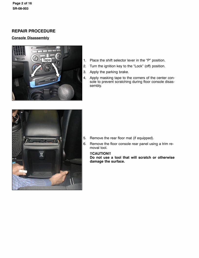
Tape 1. Place the shift selector lever in the “P” position.
2. Turn the ignition key to the “Lock” (off) position.
3. Apply the parking brake.
4. Apply masking tape to the corners of the center con‐sole to prevent scratching during floor console disas‐sembly.
5. Remove the rear floor mat (if equipped).
6. Remove the floor console rear panel using a trim re‐moval tool.
!!CAUTION!! Do not use a tool that will scratch or otherwisedamage the surface.
Page 3 of 16
SR-08-003
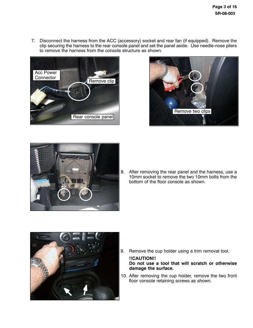
7. Disconnect the harness from the ACC (accessory) socket and rear fan (if equipped). Remove theclip securing the harness to the rear console panel and set the panel aside. Use needle-nose pliersto remove the harness from the console structure as shown.
Rear console panel
Acc PowerConnector
Remove clip
Remove two clips
8. After removing the rear panel and the harness, use a10mm socket to remove the two 10mm bolts from thebottom of the floor console as shown.
9. Remove the cup holder using a trim removal tool.
!!CAUTION!!Do not use a tool that will scratch or otherwisedamage the surface.
10. After removing the cup holder, remove the two frontfloor console retaining screws as shown.
Page 4 of 16
SR-08-003
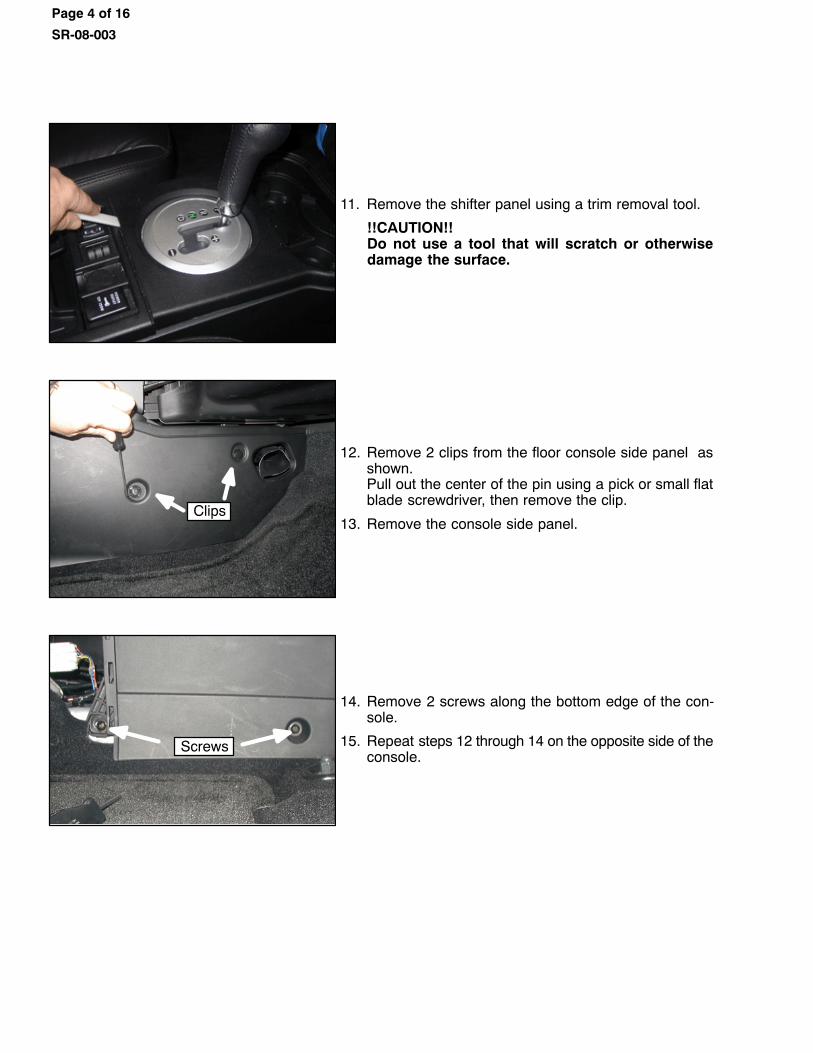
11. Remove the shifter panel using a trim removal tool.
!!CAUTION!!Do not use a tool that will scratch or otherwisedamage the surface.
Clips
12. Remove 2 clips from the floor console side panel asshown. Pull out the center of the pin using a pick or small flatblade screwdriver, then remove the clip.
13. Remove the console side panel.
Screws
14. Remove 2 screws along the bottom edge of the con‐sole.
15. Repeat steps 12 through 14 on the opposite side of theconsole.
Page 5 of 16
SR-08-003
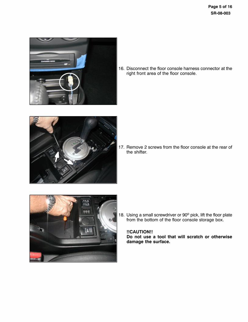
16. Disconnect the floor console harness connector at theright front area of the floor console.
17. Remove 2 screws from the floor console at the rear ofthe shifter.
18. Using a small screwdriver or 90o pick, lift the floor platefrom the bottom of the floor console storage box.
!!CAUTION!!Do not use a tool that will scratch or otherwisedamage the surface.
Page 6 of 16
SR-08-003
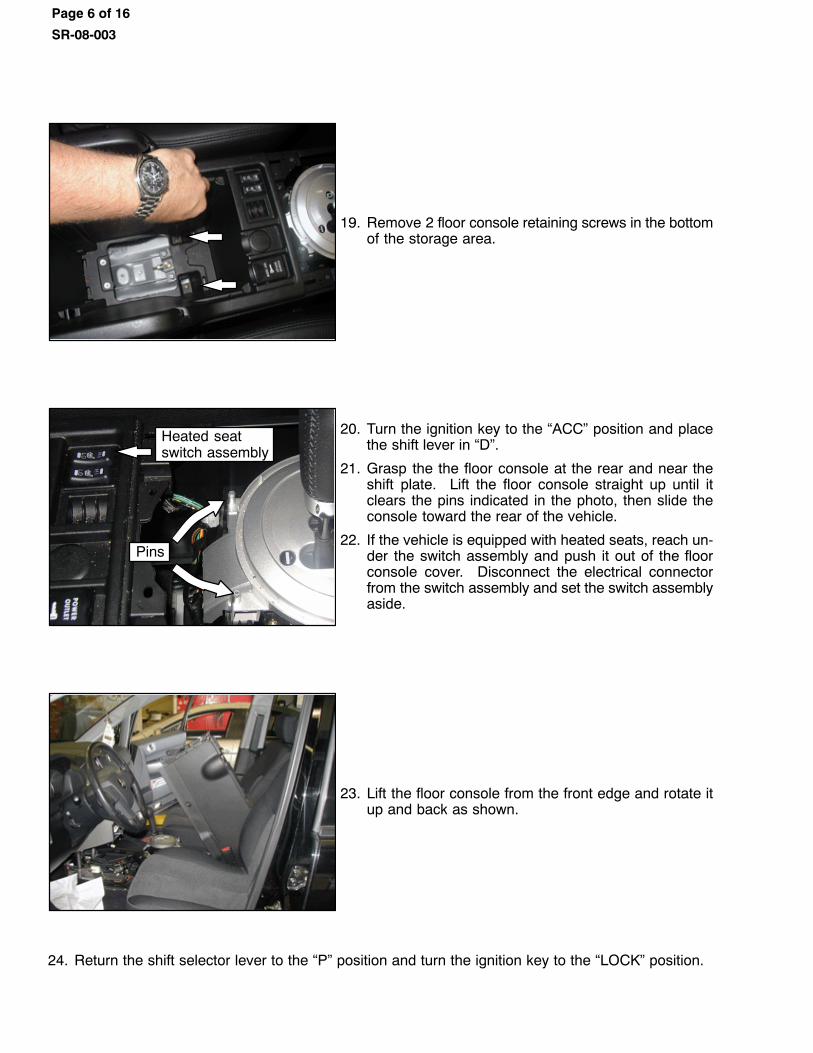
19. Remove 2 floor console retaining screws in the bottomof the storage area.
Pins
Heated seatswitch assembly
20. Turn the ignition key to the “ACC” position and placethe shift lever in “D”.
21. Grasp the the floor console at the rear and near theshift plate. Lift the floor console straight up until itclears the pins indicated in the photo, then slide theconsole toward the rear of the vehicle.
22. If the vehicle is equipped with heated seats, reach un‐der the switch assembly and push it out of the floorconsole cover. Disconnect the electrical connectorfrom the switch assembly and set the switch assemblyaside.
23. Lift the floor console from the front edge and rotate itup and back as shown.
24. Return the shift selector lever to the “P” position and turn the ignition key to the “LOCK” position.
Page 7 of 16
SR-08-003
CAM LEVER & ROD ASSEMBLY & RETURN SPRING INSTALLATION PROCEDURE
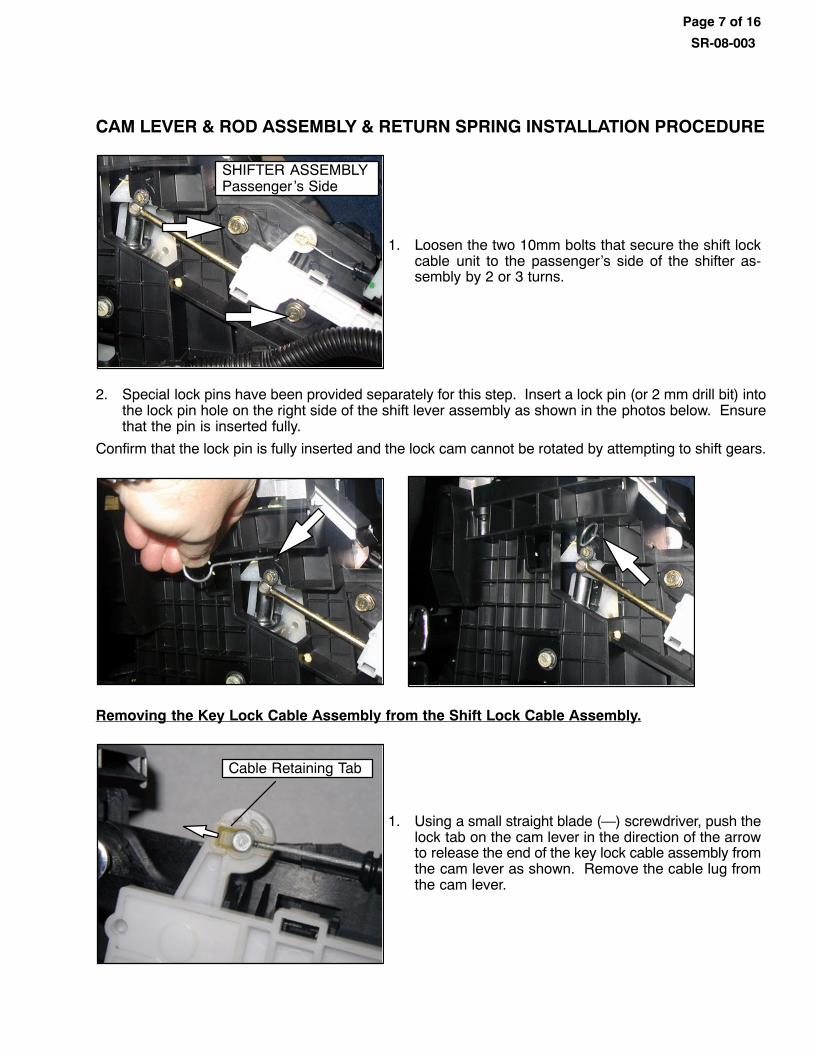
SHIFTER ASSEMBLYPassenger 's Side
1. Loosen the two 10mm bolts that secure the shift lockcable unit to the passenger's side of the shifter as‐sembly by 2 or 3 turns.
2. Special lock pins have been provided separately for this step. Insert a lock pin (or 2 mm drill bit) intothe lock pin hole on the right side of the shift lever assembly as shown in the photos below. Ensurethat the pin is inserted fully.
Confirm that the lock pin is fully inserted and the lock cam cannot be rotated by attempting to shift gears.
Removing the Key Lock Cable Assembly from the Shift Lock Cable Assembly.
Cable Retaining Tab
1. Using a small straight blade (—) screwdriver, push thelock tab on the cam lever in the direction of the arrowto release the end of the key lock cable assembly fromthe cam lever as shown. Remove the cable lug fromthe cam lever.
Page 8 of 16
SR-08-003
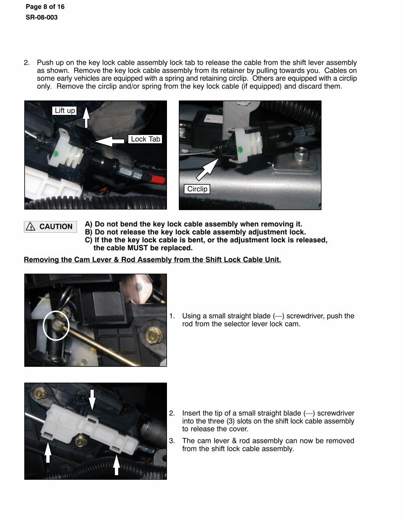
2. Push up on the key lock cable assembly lock tab to release the cable from the shift lever assemblyas shown. Remove the key lock cable assembly from its retainer by pulling towards you. Cables onsome early vehicles are equipped with a spring and retaining circlip. Others are equipped with a circliponly. Remove the circlip and/or spring from the key lock cable (if equipped) and discard them.
Lock Tab
Lift up
Circlip
CAUTION!A) Do not bend the key lock cable assembly when removing it.B) Do not release the key lock cable assembly adjustment lock.C) If the the key lock cable is bent, or the adjustment lock is released, the cable MUST be replaced.
Removing the Cam Lever & Rod Assembly from the Shift Lock Cable Unit.
1. Using a small straight blade (—) screwdriver, push therod from the selector lever lock cam.
2. Insert the tip of a small straight blade (—) screwdriverinto the three (3) slots on the shift lock cable assemblyto release the cover.
3. The cam lever & rod assembly can now be removedfrom the shift lock cable assembly.
Page 9 of 16
SR-08-003
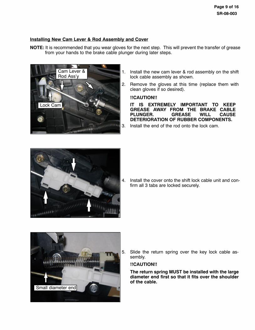
Installing New Cam Lever & Rod Assembly and Cover
NOTE: It is recommended that you wear gloves for the next step. This will prevent the transfer of greasefrom your hands to the brake cable plunger during later steps.
Cam Lever &Rod Ass'y
Lock Cam
1. Install the new cam lever & rod assembly on the shiftlock cable assembly as shown.
2. Remove the gloves at this time (replace them withclean gloves if so desired).
!!CAUTION!!
IT IS EXTREMELY IMPORTANT TO KEEPGREASE AWAY FROM THE BRAKE CABLEPLUNGER. GREASE WILL CAUSEDETERIORATION OF RUBBER COMPONENTS.
3. Install the end of the rod onto the lock cam.
4. Install the cover onto the shift lock cable unit and con‐firm all 3 tabs are locked securely.
Small diameter end
5. Slide the return spring over the key lock cable as‐sembly.
!!CAUTION!!
The return spring MUST be installed with the largediameter end first so that it fits over the shoulderof the cable.
Page 10 of 16
SR-08-003
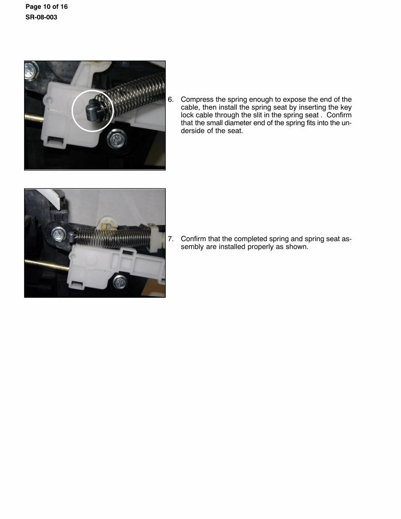
6. Compress the spring enough to expose the end of thecable, then install the spring seat by inserting the keylock cable through the slit in the spring seat . Confirmthat the small diameter end of the spring fits into the un‐derside of the seat.
7. Confirm that the completed spring and spring seat as‐sembly are installed properly as shown.
Page 11 of 16
SR-08-003
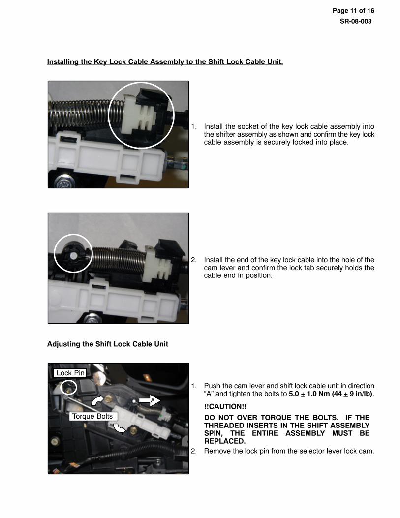
Installing the Key Lock Cable Assembly to the Shift Lock Cable Unit.
1. Install the socket of the key lock cable assembly intothe shifter assembly as shown and confirm the key lockcable assembly is securely locked into place.
2. Install the end of the key lock cable into the hole of thecam lever and confirm the lock tab securely holds thecable end in position.
Adjusting the Shift Lock Cable Unit
Torque Bolts
A
Lock Pin
1. Push the cam lever and shift lock cable unit in direction“A” and tighten the bolts to 5.0 + 1.0 Nm (44 + 9 in/lb).
!!CAUTION!!
DO NOT OVER TORQUE THE BOLTS. IF THETHREADED INSERTS IN THE SHIFT ASSEMBLYSPIN, THE ENTIRE ASSEMBLY MUST BEREPLACED.
2. Remove the lock pin from the selector lever lock cam.
Page 12 of 16
SR-08-003
SHIFT LOCK SYSTEM FUNCTION INSPECTIONPerform the following shift lock system function check BEFORE floor console reassembly. Shift gearsbetween P and N to insure that the key cannot be removed unless the transmission selector is in the Pposition. Insure that the shifter moves smoothly when gear selections are made.
1. Check Lock Cam operation with shift lever in ”N” position:
a) Start engine with shift lever in ”P” position.
b) Depress the brake pedal.
c) Push the shift lever button with minimum stroke possible, and move shift lever to ”N” position.
d) Depress the brake pedal full stroke and then release. Repeat this procedure 20 times at2 second intervals.
e) Confirm the ignition key cannot be turned to the ”LOCK” position and the key cannotbe removed.
f) Move the shift lever to the ”P” position.
2. Confirm the removal of the ignition key from the key cylinder with the shift lever in the ”P” position:
a) Start the engine with the shift lever in the ”P” position.
b) Depress the brake pedal.
c) Push the shift lever button with full stroke and move the shift lever to the ”N” position.
d) Continue to depress the brake pedal, push the button on the shift lever with full stroke, and movethe shift lever to the ”P” position. Release the shift lever button slowly (about 5 seconds).
f) Confirm the ignition key can be turned to the ”LOCK” position and removed.
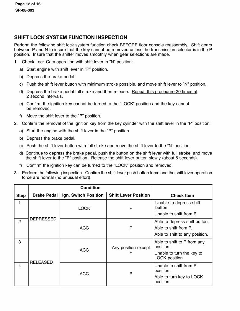
3. Perform the following inspection. Confirm the shift lever push button force and the shift lever operationforce are normal (no unusual effort).
Step
Condition
Check ItemBrake Pedal Ign. Switch Position Shift Lever Position
1
DEPRESSED
LOCK PUnable to depress shiftbutton.
Unable to shift from P.
2
ACC P
Able to depress shift button.
Able to shift from P.
Able to shift to any position.
3
RELEASED
ACC Any position exceptP
Able to shift to P from anyposition.
Unable to turn the key toLOCK position.
4
ACC P
Unable to shift from Pposition.
Able to turn key to LOCKposition.
Page 13 of 16
SR-08-003
CONSOLE REASSEMBLY1. Reassemble the console in the reverse order of disassembly.
2. Confirm that all electrical connections and fasteners are properly secured.
� Confirm that the accessory power sockets function.
� Confirm function of the heated seats (if equipped) and that the switches illuminate when in theON position.
� Confirm function of the rear fan (if equipped).
3. Remove the tape protecting the center console.
PARTS INFORMATION
PARTS MANAGER: Refer to Parts Bulletin AI-ED-01-08 for additional details.
A supply of Shift Interlock Repair Kits will be allocated to each dealer. Determine your actual needs beforeordering additional parts.
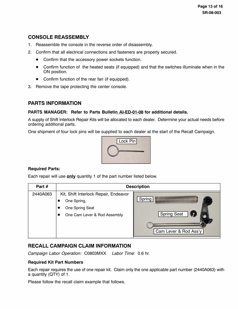
One shipment of four lock pins will be supplied to each dealer at the start of the Recall Campaign.
Lock Pin
Required Parts:
Each repair will use only quantity 1 of the part number listed below.
Part # Description
2440A063 Kit, Shift Interlock Repair, Endeavor
� One Spring,
� One Spring Seat
� One Cam Lever & Rod Assembly
Spring
Spring Seat
Cam Lever & Rod Ass'y
RECALL CAMPAIGN CLAIM INFORMATIONCampaign Labor Operation: C0803MXX Labor Time: 0.6 hr.
Required Kit Part Numbers
Each repair requires the use of one repair kit. Claim only the one applicable part number (2440A063) witha quantity (QTY) of 1.
Please follow the recall claim example that follows.
Page 14 of 16
SR-08-003
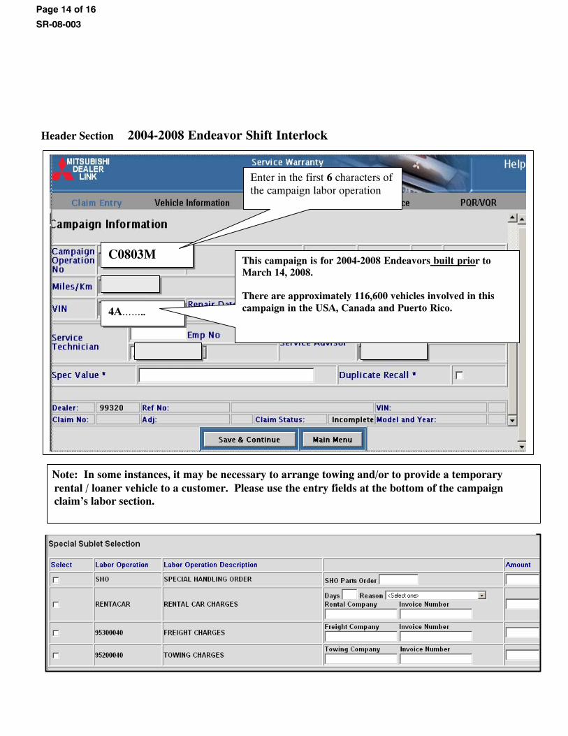
Header Section 2004-2008 Endeavor Shift Interlock
C0803M
4A��..
This campaign is for 2004-2008 Endeavors built prior toMarch 14, 2008. There are approximately 116,600 vehicles involved in thiscampaign in the USA, Canada and Puerto Rico.
Enter in the first 6 characters of the campaign labor operation
Note: In some instances, it may be necessary to arrange towing and/or to provide a temporaryrental / loaner vehicle to a customer. Please use the entry fields at the bottom of the campaignclaim's labor section.
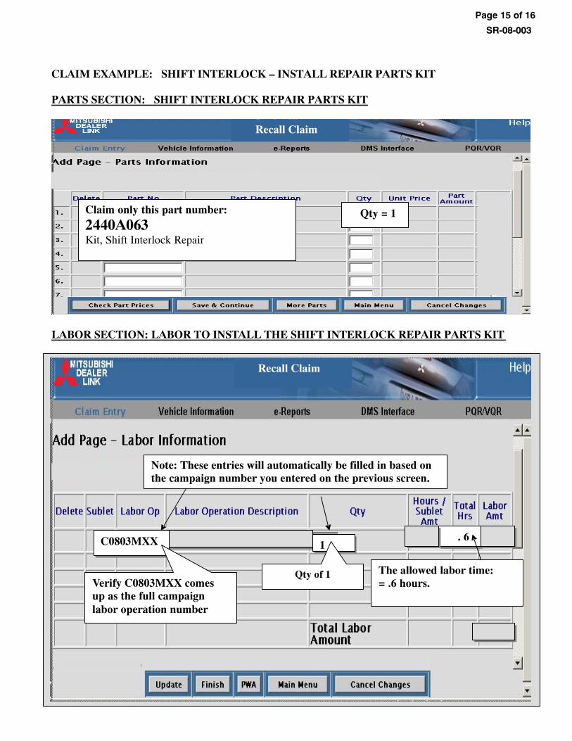
CLAIM EXAMPLE: SHIFT INTERLOCK – INSTALL REPAIR PARTS KIT PARTS SECTION: SHIFT INTERLOCK REPAIR PARTS KIT
Recall Claim
Claim only this part number:
2440A063Kit, Shift Interlock Repair
Qty = 1
LABOR SECTION: LABOR TO INSTALL THE SHIFT INTERLOCK REPAIR PARTS KIT
SCENARIO 1: UPON INSPECTION NO “5D08” CALIPERSWERE FOUND
PARTS SECTI NLY CLAIMSON: NO PARTS ARE ALLOWED FOR INSPECTION O
SCENARIO 2: UPON INSPECTION – THE CROSSMEMBER REQUIRES REPLACEMENT
Recall Claim
C0803MXX 1 . 6
Verify C0803MXX comes up as the full campaignlabor operation number
Qty of 1
Note: These entries will automatically be filled in based on the campaign number you entered on the previous screen.
The allowed labor time: = .6 hours.
Page 15 of 16
SR-08-003
Page 16 of 16
SR-08-003
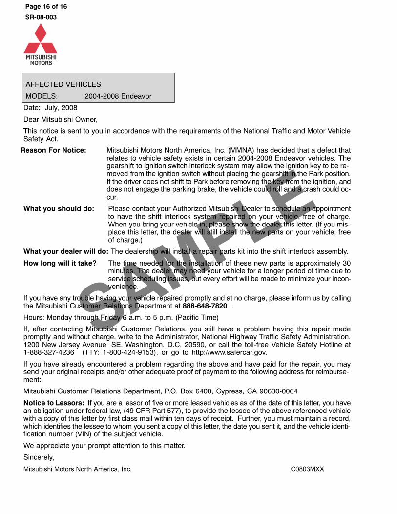
AFFECTED VEHICLES
MODELS: 2004-2008 Endeavor
Date: July, 2008
Dear Mitsubishi Owner,
This notice is sent to you in accordance with the requirements of the National Traffic and Motor VehicleSafety Act.
Reason For Notice: Mitsubishi Motors North America, Inc. (MMNA) has decided that a defect thatrelates to vehicle safety exists in certain 2004-2008 Endeavor vehicles. Thegearshift to ignition switch interlock system may allow the ignition key to be re‐moved from the ignition switch without placing the gearshift in the Park position.If the driver does not shift to Park before removing the key from the ignition, anddoes not engage the parking brake, the vehicle could roll and a crash could oc‐cur.
What you should do: Please contact your Authorized Mitsubishi Dealer to schedule an appointmentto have the shift interlock system repaired on your vehicle, free of charge.When you bring your vehicle in, please show the dealer this letter. (If you mis‐place this letter, the dealer will still install the new parts on your vehicle, freeof charge.)
What your dealer will do: The dealership will install a repair parts kit into the shift interlock assembly.
How long will it take? The time needed for the installation of these new parts is approximately 30minutes. The dealer may need your vehicle for a longer period of time due toservice scheduling issues, but every effort will be made to minimize your incon‐venience.
If you have any trouble having your vehicle repaired promptly and at no charge, please inform us by callingthe Mitsubishi Customer Relations Department at 888-648-7820 .
Hours: Monday through Friday 6 a.m. to 5 p.m. (Pacific Time)
If, after contacting Mitsubishi Customer Relations, you still have a problem having this repair madepromptly and without charge, write to the Administrator, National Highway Traffic Safety Administration,1200 New Jersey Avenue SE, Washington, D.C. 20590, or call the toll-free Vehicle Safety Hotline at1-888-327-4236 (TTY: 1-800-424-9153), or go to http://www.safercar.gov.
If you have already encountered a problem regarding the above and have paid for the repair, you maysend your original receipts and/or other adequate proof of payment to the following address for reimburse‐ment:
Mitsubishi Customer Relations Department, P.O. Box 6400, Cypress, CA 90630-0064
Notice to Lessors: If you are a lessor of five or more leased vehicles as of the date of this letter, you havean obligation under federal law, (49 CFR Part 577), to provide the lessee of the above referenced vehiclewith a copy of this letter by first class mail within ten days of receipt. Further, you must maintain a record,which identifies the lessee to whom you sent a copy of this letter, the date you sent it, and the vehicle identi‐fication number (VIN) of the subject vehicle.
We appreciate your prompt attention to this matter.
Sincerely,
Mitsubishi Motors North America, Inc. C0803MXX