SAFETY, OPERATION, AND MAINTENANCE PREGIS 1815ACM...
52
SAFETY, OPERATION, AND MAINTENANCE PREGIS 1815ACM AIR CUSHION MACHINE (Part No. 153512) 01-08-07
Transcript of SAFETY, OPERATION, AND MAINTENANCE PREGIS 1815ACM...

SAFETY, OPERATION, AND MAINTENANCE
PREGIS 1815ACM
AIR CUSHION MACHINE
(Part No. 153512)
01-08-07

SECTIONINSTRUCTION . . . . . . . . . . . . . . . . . . . . . . . . . . . . . . . . . . . . . . . . . . . . . . . . . . . . . . . .NUMBER
1 SAFETYOPERATING SAFETY . . . . . . . . . . . . . . . . . . . . . . . . . . . . . . . . . . . . . . . . . . . . . . . . . . . . . . .1-1SAFETY ALERTS . . . . . . . . . . . . . . . . . . . . . . . . . . . . . . . . . . . . . . . . . . . . . . . . . . . . . . . . . . .1-2
2 OPERATIONINTRODUCTION . . . . . . . . . . . . . . . . . . . . . . . . . . . . . . . . . . . . . . . . . . . . . . . . . . . . . . . . . . . .2-1OPERATOR CONTROLS . . . . . . . . . . . . . . . . . . . . . . . . . . . . . . . . . . . . . . . . . . . . . . . . . . . . .2-2MANAGEMENT INTERFACE SCREENS . . . . . . . . . . . . . . . . . . . . . . . . . . . . . . . . . . . . . . . . .2-3OPERATING PROCEDURE . . . . . . . . . . . . . . . . . . . . . . . . . . . . . . . . . . . . . . . . . . . . . . . . . . .2-4
3 MAINTENANCEDRIVE BELT REPLACEMENT . . . . . . . . . . . . . . . . . . . . . . . . . . . . . . . . . . . . . . . . . . . . . . . . .3-1SEALING DRUM REPLACEMENT . . . . . . . . . . . . . . . . . . . . . . . . . . . . . . . . . . . . . . . . . . . . . .3-2HEIGHT ADJUSTMENT . . . . . . . . . . . . . . . . . . . . . . . . . . . . . . . . . . . . . . . . . . . . . . . . . . . . . .3-3MAINTENANCE SCHEDULE . . . . . . . . . . . . . . . . . . . . . . . . . . . . . . . . . . . . . . . . . . . . . . . . . .3-4
4 TROUBLESHOOTINGTROUBLESHOOTING . . . . . . . . . . . . . . . . . . . . . . . . . . . . . . . . . . . . . . . . . . . . . . . . . . . . . . .4-1
TABLE OF CONTENTS - 1815ACM
TABLE OF CONTENTS
Page 1 of 1
02-23-07Copyright© Pregis Corp.
All Rights Reserved

Operator safety and the safety of others in the workarea depends on the operator using common sense,good judgement and reasonable care while operat-ing the machine. The Safety, Operation andMaintenance manual, and warning labels affixed tothe machine, provide notification of specific poten-tial hazards.
NOTE: Refer to the Safety Alerts instruction foradditional safety-related information.
Safety
The following instructions are only a guideline andshould be considered a supplement to your plant'scomprehensive safety program. Your business' pol-icy supercedes these guidelines if at any time thetwo contradict each other.
1. Read and understand the manual. If after read-ing the manual you have questions, getanswers before working with the machine.
2. Read and understand all of the danger, warn-ing and caution statements in the manual andon the signs attached to the equipment.
3. Never deface or remove factory installedwarning decals. If a decal ever becomes lost,damaged or illegible, report this condition to asupervisor and obtain a replacement decal.
4. Keep the work area clean and uncluttered.Walking surfaces should always be free ofpacking material and debris to prevent a slip-ping or tripping hazard.
5. Ensure that all covers, guards and other safetydevices are in place. Never defeat a safetydevice for any reason.
6. Follow the manufacturer's recommended start-up procedure.
7. Never leave the equipment unattended whileoperating. Shut the machine off if you mustleave the work area.
8. Keep body parts and clothing away from mov-ing components such as nip rolls, power trans-mission components, sealing belts, etc. Neverreach into the machine for any reason while itis in motion.
9. Understand what will happen when you oper-ate the various controls.
10. Understand the proper web path and the safemethod for threading the web.
11. Learn the safe procedure for clearing themachine of web wraps or jams.
12. Exercise extreme care whenever it is requiredto inspect or adjust the machine while it is inmotion. NEVER reach into the machine forany reason while it is motion.
13. Understand which adjustments are operatoradjustments; contact a maintenance person tomake all other adjustments.
14. Never operate or work around equipment ifyou are under the influence of alcohol, drugsor medications that can make you less alert oraffect your judgement.
Publication 1-1
Page 1 of 1
08-30-06Copyright© Pregis Corp.
All Rights Reserved
OPERATING SAFETY1815ACMAIR CUSHION MACHINE

Operator safety and the safety of others in the workarea depends on the operator using common sense,good judgement and reasonable care while operat-ing the machine. The Safety, Operation andMaintenance manual, and warning labels affixed tothe machine, provide notification of specific poten-tial hazards.
Safety signs are used to alert operating and mainte-nance personnel to potential hazards. The machinemanual also calls attention to potential hazardswith statements describing the hazard. Both thesafety signs on the machine and the warnings in themanual use signal words to identify the seriousnessof the potential hazard. These signal words areDanger, Warning and Caution.
The meanings of the signal words and the level ofpotential hazards they represent must be clearlyunderstood before attempting to operate or main-tain the machine. If, at any time, a safety sign onthe machine becomes lost, damaged or illegible,contact Pregis to order replacement signs at nocharge.
Publication 1-2
Page 1 of 1
08-30-06Copyright© Pregis Corp.
All Rights Reserved
SAFETY ALERTS1815ACMAIR CUSHION MACHINE
A definitely hazardous situation that, if notavoided, will result in serious injury ordeath.
A potentially hazardous situation that, ifnot avoided, could result in serious injuryor death.
A potentially hazardous situation that, ifnot avoided, may result in minor injury (ormachine damage).

Introduction
The Pregis 1815ACM (Figure 1) produces panelsof air-filled packing cushions in any quantity, asneeded. The ability to create packing cushions ondemand saves storage space and reduces packagingmaterial waste.
Film parent roll up to 18" (457mm) wide by 9"(229mm) diameter on 3" (76mm) ID paper cores.Packing cushions are created in panels of individ-ual cushions.
A string of panels can be torn apart at perforationscut between each panel. Cushions are created at aconstant rate of up to 75 feet per minute (fpm) offilm feed.
Operation
The film web is a continuous tube with a seal pre-applied across the web every 1.88". A perforationhas also been pre-made every 15". The cross sealsend exactly 0.533" from one sealed edge of thefilm. This creates an unsealed gap, in the filmdirection, along that edge of the film.
Publication 2-1
Page 1 of 6
02-12-07Copyright© Pregis Corp.
All Rights Reserved
INTRODUCTION1815ACMAIR CUSHION MACHINE
Figure 11815ACM Air Cushion Machine

INTRODUCTION - 1815ACM
Publication 2-1
Page 2 of 6
The parent roll of film is loaded into the unwindcradle with the air pipe channel edge towards the
inside. The parent roll is supported on two rotatingcradle rollers. A pair of angled guide rods are usedto hold the film parent roll in a fixed position side-to-side. The guide rod positions may be adjusted toalign film air fill slot with the air injection pipe.See Figure 2.
From the unwind cradle, the film is routed aroundseveral idler rollers that change its direction toroute it into the sealing section. A spring-loadedbrake strap is wrapped around two of the idlerrollers on the unwind cradle. The brake strap pro-vides a braking action on the parent roll to create a
02-12-07Copyright© Pregis Corp.
All Rights Reserved
Figure 2Film Parent Roll Cradle
DO NOTOperate WithHood Open!
SeeFigure 4
Drive Belts Nip
Air Pipe
FilmRoller
Hood
CoverGuard
Electrical shock or unexpected machinemovement can cause injury. DO NOToperate machine with guards removed orcovers open.
For your safety, follow your company’slockout/tagout policy as required for eachtask.
See Figure 3 Film Roller
GuideRod
Film Parent Roll
CradleRollers
InfeedIdler
Roller

slight tension in the film between the parent rolland drive belts nip. The braking also prevents theroll from continuing to spin when the machine isstopped. See Figures 2 and 3.
The film web has a tendency to sag down when itleaves the infeed idler roller. Sagging restricts thethe air fill flow during the filling process. A pair ofspring-loaded tow rolls, on the side opposite the airinjection pipe, are at a 5°-10° downstream angle tothe film, pulling it tight. Tow roll pressure isenough to hold and guide the film, but not enoughto restrict air flow into the cushions. See Figure 4.
INTRODUCTION - 1815ACM
Publication 2-1
Page 3 of 6
02-12-07Copyright© Pregis Corp.
All Rights Reserved
Figure 3Film Parent Roll Brake
Figure 4Film Tow Rolls
TowRolls
Setscrews (4)
Sensor Sensor
CradleRoller
FilmIdler
Roller
Brake Strap
GuideRod
InfeedIdler
Roller

INTRODUCTION - 1815ACM
A proximity sensor is mounted at the outfeed end ofthe tow rolls. The sensor detects the four setscrewsembedded in the edge of the lower tow roll. Thesensor acts as a counter for detecting and measur-ing film feed. This value is used to run the machinefor a given distance of film, and then automaticallystop. The film counter also acts as a "Film Out" or"Web Break" detector. If the PLC sees the counterstop, it then stops the machine and displays a mes-sage. See Figure 4.
An upper and lower drive belt are each routedaround a tensioner flanged guide roller, three idlers,the sealing drum and the drive pulley. The beltsfollow the same path for about half their lengths,with surface contact providing a nip section thatcaptures the film. See Figure 5.
Publication 2-1
Page 4 of 6
02-12-07Copyright© Pregis Corp.
All Rights Reserved
Figure 5Film Drive Belts
DO NOT OperateWith Hood Open!
Hood
SealingDrum Tensioner
GuideRoller
Tensioner Guide Roller
Idler
Idler
DrivePulley
Idler Air Pipe
UpperBelt
Lower Belt
SlitterBlade
Air Injection Pipe
Air Outlet Slot
Air InjectionPipe
Nip PointFinger Guard
Angled FilmGuide Finger
Idler

INTRODUCTION - 1815ACM
Publication 2-1
Page 5 of 6
NOTE: The belts also provide the drive tounwind the film from the parent roll.
The upper belt is direct-driven by an electric gear-motor, through a coupling. The pressure betweenthe two belts is sufficient to drive the film, containthe air in the cushions, hold the film against thesealing drum surface, drive the drum, and drive thelower belt. See Figure 6.
A self-contained air compressor generates the airpressure used to inflate the cushions. Just upstreamof the drive belts initial nip point, air is injectedinto the cushions through an outlet slot in the airpipe. The edge of the inflating cushion is then cap-tured between the upper and lower belts, whichcontain the cushion air while providing pressureover the sealing drum. See Figure 6.
02-12-07Copyright© Pregis Corp.
All Rights Reserved
Figure 6Drive Enclosure Components
DO NOT OperateWith Hood Open!
Air Compressor
GearmotorAssembly
DrivePulley
Coupling
Slip Ring

INTRODUCTION - 1815ACM
Publication 2-1
Page 6 of 6
A slitter blade cuts the film edge open once the airhas been trapped in the cushions. This releases thefilm from the air pipe and allows the film to followthe belt path. The slitter blade is partially insertedinto a recess in the air pipe to prevent film fromsnagging on the tip of the blade. The blade is locat-ed just past the drive belts initial nip point. Anangled guide finger ahead of the slitter blade guidesthe film edge skirt downward so it does not inter-fere with the slitter blade, improving slitting con-sistency. See Figure 5.
The sealing drum contains a thin-film heater ringwhich heats up and cools down quickly. Electricpower is supplied to the heater ring through a slipring on the inside end of the hollow axle shaft. Asensor within the drum detects temperature forheater control. See Figure 6.
The sealing drum is mounted to the axle shaft bythree sockethead capscrews. Removing thesescrews allows access to the electrical connectionsinside the axle. The heater connection is made witha plug and socket. The sealing drum axle shaft issupported by a pair of bearing housings. The bear-ings do not require lubrication or maintenance.Refer to the Sealing Drum Replacement instruc-tion.
The drive belts carry the trapped layers of filmaround the sealing drum and then around an idler toallow the film to cool down before it is released.
02-12-07Copyright© Pregis Corp.
All Rights Reserved

Controls
NOTE: Refer to Figure 1 for items 1 through 8.
1. Operator Interface ScreenUsed to monitor, select and adjust the air cush-ion machine operating parameters.
2. (Up/Down) ArrowsUsed to navigate through various displayscreens. Screens may be password-protectedand accessible only by maintenance personnel.
3. +/- (Plus/Minus)Used to increase or decrease quantity, such asthe length of film run or sealing wire tempera-ture. When pressed and released, they actmomentarily, changing the value in incrementsof one (1). When pressed and held, the valuechanges in larger increments.
4. STARTUsed to run the machine during normal opera-tion.
Publication 2-2
Page 1 of 7
02-15-07Copyright© Pregis Corp.
All Rights Reserved
OPERATOR CONTROLS1815ACMAIR CUSHION MACHINE
Figure 1Operator Control Panel (Outfeed End)
12
4 765
38
HoodCoverGuard
OPERATOR CONTROLS - 1815ACM
Publication 2-2
Page 2 of 7
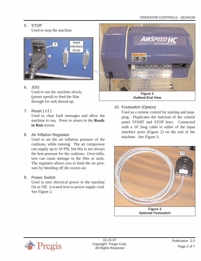
5. STOPUsed to stop the machine.
6. JOGUsed to run the machine slowly (preset speed) to feed the film through for web thread-up.
7. Reset ( / / )Used to clear fault messages and allow themachine to run. Press to return to the Readyto Run screen.
8. Air Inflation RegulatorUsed to set the air inflation pressure of thecushions, while running. The air compressorcan supply up to 10 PSI, but this is not alwaysthe best pressure for the cushions. Over-infla-tion can cause damage to the film or seals.The regulator allows you to limit the air pres-sure by bleeding off the excess air.
9. Power SwitchUsed to turn electrical power to the machineOn or Off. Located next to power supply cord.See Figure 2.
10. Footswitch (Option)Used as a remote control for starting and stop-ping. Duplicates the function of the controlpanel START and STOP keys. Connectedwith a 10' long cable to either of the inputinterface ports (Figure 2) on the end of themachine. See Figure 3.
02-15-07Copyright© Pregis Corp.
All Rights Reserved
Figure 2Outfeed End View
Figure 3Optional Footswitch
10
InputInterface
Ports
9

OPERATOR CONTROLS - 1815ACM
Publication 2-2
Page 3 of 7
Operator Interface Touchscreen
The operation of the Interface Screens are separat-ed into four (4) levels of security defined by pass-words that allow access only to specific personnel.
The access levels are defined as:
OperatorLead OperatorManagementTechnician
Each level of access allows varying access to thefollowing screens:
Main (Ready to Run)Machine Setup
Parameter SetupRecipe
Use the Up/Down arrow ( ) keys to select a spe-cific line/function. The cursor ( ) moves to theselected line.
Use the Plus/Minus (+/-) keys to change the Actualvalue, or accept the line/function choice whichroutes you to the applicable parameter.
Initial Startup Screen
This screen will appear when power is first applied.It will remain visible for several seconds. The PLCand HMI (Human-Machine Interface) screens soft-ware versions are listed here. See Figure 4.
Main Screen
This screen allows the operator to view the currentstatus of the machine, select the operating mode,and access additional screens to change settings, ifthe required password is entered. See Figure 5.
OPERATING STATUS
At the top of the Main screen is a message displaybox that displays the current operating status of themachine, such as:
Ready To RunThe machine has no existing faults, and isready to be started. See Figures 6 and 7.
PAUSEDThe machine has been started, but is not mak-ing cushions. The machine is using a sensor tolook at the Collection Bin (or winder). Thesensor is detecting that the bin is full, or thewinder is not ready for more cushions. SeeFigure 8.
RUNNINGThe machine has been started, and it is makingcushions. If the Main screen displays themachine as in the “Automatic Stop” or “Fillthe Basket” mode, the machine will then auto-matically stop when the correct length of filmhas been run.
02-15-07Copyright© Pregis Corp.
All Rights Reserved
Figure 4Initial Startup screen

JOGGINGThe blue JOG key is being pressed and thedrive belts are being advanced. In this mode,there is no air inflation or heat being applied tothe film.
NOTE: The JOG key is an easy way to threadthe film into the machine.
OPERATING MODES
The first line(s) below the current operating statusbox displays the machine operating modes. Thethree (3) operating modes include:
Normal OperationThe machine is manually started, and will runcontinuously until manually stopped. Otherthan pressing the STOP key or the remotefootswitch, the only other thing that will stopthe machine is a fault condition, such as run-ning out of film. See Figure 5.
Automatic Stopafter xx ft.
Used to run a specific length of film. Themachine is manually started, and will run untila length of film cushions have been produced.The machine can be manually stopped beforethe length has been reached with either theSTOP key or the remote footswitch.
The length can be changed by using theUp/Down arrow ( ) keys to move to the“after XX ft” line, and then pressing thePlus/Minus (+/-) keys to change the length.The length set will be the same for both theAutomatic Stop (Figure 6) or Fill The Basket(Figure 7) parameters.
Fill The Basketwith xx ft.
Used to automatically run a specific length offilm each time the collection basket/bin isempty. The START key must be initiallypressed after this mode is selected.
A sensor mounted above the bin detects whenthe bin is empty. The selected length of film isthen run. This is similar to “Automatic Stop”mode, but the machine does not have to be re-started every time.
After the sensor initially detects the bin asempty, there is a four second delay before thecushion machine is started. This prevents thecushion machine from pulsing on and off.
Once the preset length of film has been run,the Main screen “RUNNING” messagechanges to “PAUSED”, and the machine stops.See Figure 7.
The machine can be manually stopped at anytime with either the STOP key or the remotefootswitch.
OPERATOR CONTROLS - 1815ACM
Publication 2-2
Page 4 of 7
02-15-07Copyright© Pregis Corp.
All Rights Reserved
Figure 6Main screen - Automatic Stop
Figure 5Main screen - Normal Operation

OPERATOR CONTROLS - 1815ACM
Publication 2-2
Page 5 of 7
Use the Down arrow ( ) key to select a specificline. The cursor ( ) moves to the selected line.Use the Plus (+) keys to accept the line choice.
The “Setup the Machine” line takes you to theMachine Setup screen (Figure 8). The “SealTemperature” line takes you to the ParameterSetup - Seal Temperature screen (Figure 9).
Machine Setup Screen
This screen allows access to the Parameter Setup,Load Recipe and Save Recipe screens. All userscan access the Parameter Setup and Password func-tions. See Figure 8.
When the cursor ( ) is on the Password line, thePlus/Minus (+/-) keys will change the value of thepassword. When no password is entered (0), press-ing the up/down arrow ( ) keys will only movethe cursor ( ) between the Parameter Setup andPassword lines.
When the cursor ( ) is on the Parameter Setupline, the Plus (+) key will take you to theParameter Setup - Seal Temperature screen. SeeFigure 9.
Enter the Lead Operator (or Management) pass-word and the cursor ( ) will now scroll down tothe Load Recipe line. The Plus (+) key will takeyou to the Load Recipe screen. See Figure 11.
Parameter Setup Screen
NOTE: The Parameter Setup screen (Figure 9)is accessed from either the Main screen(Figures 5, 6 or 7) or the MachineSetup screen (Figure 8).
This screen allows changes to a number of machineparameters, such as temperatures, speeds, timing,languages and limits. Seal Temperature (Figure 9)and Password (Figure 10) are the only parameterswhich an operator can access.
NOTE: Only authorized password-accessallows the remaining parameter settingsto be changed.
02-15-07Copyright© Pregis Corp.
All Rights Reserved
Figure 8Machine Setup screen
Figure 7Main screen - Fill The Basket
Figure 9Parameter Setup - Seal Temperature

OPERATOR CONTROLS - 1815ACM
Publication 2-2
Page 6 of 7
Press the Up/Down arrow ( ) keys to scrollthrough the available parameter screens. On theParameter Setup - Password screen (Figure 10),the Plus/Minus (+/-) keys will change the value ofthe password.
For the specific parameter, the current Actualvalue, possible Minimum/Maximum values, aswell as the Units of measure are displayed. Not allof these lines are active on all screens.
Changing Parameter Actual Value
1. Scroll to the desired parameter (such as SealTemperature, Figure 9).
NOTE: The desired sealing temperature for run-ning 1.5mil mono-layer film at 75fpm is285°F.
2. Use the Plus/Minus (+/-) keys to change theActual value. The value takes effect as it ischanged and does not require a special step toactivate.
3. When you are done changing the value, either:
a. Press the Up/Down arrow ( ) keys to view/edit other parameters, or
b. Press the yellow RESET key to exit the Parameter Setup screen and return to the Main screen.
Load Recipe Screen
NOTE: The Load Recipe screen (Figure 11) isaccessed from the Machine Setupscreen (Figure 8), as long as an author-ized password has first been entered.
This screen allows the machine to operate usingone of four existing recipes. Press the Up/Downarrow ( ) keys to scroll the cursor ( ) up anddown. Press the Plus (+) key to select the desiredrecipe. The screen will indicate that the recipe hasbeen loaded. Press the Start, Stop, Jog or Resetkeys (Figure 1) to return to the Main screen(Figures 5, 6 or 7).
02-15-07Copyright© Pregis Corp.
All Rights Reserved
Figure 11Load Recipe screen
Figure 10Parameter Setup - Password
OPERATOR CONTROLS - 1815ACM
Publication 2-2
Page 7 of 7
Fault Messages
At the top of the Main screen is a message displayfield. In addition to listing the current operatingcondition of the machine, a fault message mayappear in this field. Some messages go away ontheir own, and some require the operator to pressthe yellow RESET key to clear the fault condition.Definitions of each of the special fault messagesare as follows:
COVER GUARD IS OPENThe machine has a cover guard hood to help pre-vent injury from the moving internal parts of themachine. The cover guard hood must be closedbefore the machine can be started.
FILM RUNOUT OR JAMWhile running, the machine detected that the filmhad stopped moving at the unwind. This is causedwhen the film parent roll has run out, the film par-ent roll has stopped turning, or the film tore off at aperforation, possibly jamming.
SEAL HEAT WIRE OPENThe heater has a sensor that allows the PLC to con-trol the temperature of the seal. If the sensor fails,the machine is shut down to prevent film waste.
UNDER TEMPERATUREWhile running, the temperature of the heater fellbelow or did not reach the required level for sever-al seconds. This usually indicates that some part inthe heater system has failed and requires service.
REPLACE DRIVE BELTSThis message appears when the “Belt Odometer”value reaches the preset limit. The message can becleared, by a Manager or Technician, by reducingthe value in the Belt Odometer parameter Actualfield to zero.
02-15-07Copyright© Pregis Corp.
All Rights Reserved
The machine can be jogged with the coverguard hood open. Use caution whenthreading the machine.

OPERATOR CONTROLS - 1815ACM
Publication 2-2
Page 8 of 7
02-15-07Copyright© Pregis Corp.
All Rights Reserved
Operator Interface Touchscreen
The operation of the Interface Screens are separat-ed into four (4) levels of security defined by pass-words that allow access only to specific personnel.
The access levels are defined as:
OperatorLead OperatorManagementTechnician
Each level of access allows varying access to thefollowing screens:
Main (Ready to Run)Machine Setup
Parameter SetupRecipe
Seal Temperature is the only parameter which anoperator can access. This parameter sets the levelof heat being used to seal the film together. Accessto this parameter is offered as a shortcut on theMain screen. It is also the first value listed on theParameter Setup screen. Management and LeadOperators may also load recipes.
On the Machine Setup screen (Figure 5), enter theManagement (or Lead Operator) password and thecursor ( ) will now scroll down to the LoadRecipe line. The Plus (+) key will take you to theLoad Recipe screen. See Figure 6.
The passwords for both the Lead Operator andManagement levels are set at the Technician level.The Technician level password has been pro-grammed into the system and can not be changed.
NOTE: Once you leave the Password parame-ter, the password value shown at Actualreturns to the default of zero (0).
Management Access Level
Managers can access all parameters at the Operatorand Lead Operator levels, as well as four addition-al Parameter Setup parameter screens:
Belt Odometer (km)Distance Selection (Metric/English)Temperature Scale (ºF/ºC)Language Selection
For all Parameter Setup screen parameters, thearrow cursor ( ) designates the active Actual valueline. Use the Plus/Minus (+/-) keys to change theline value. Press the Up/Down arrow ( ) keysto accept the new value and move to anotherparameter.
NOTE: At any access level, on any screen,pressing the RESET key returns you tothe Main screen. Refer to the OperatorControls instruction.
Belt OdometerThis value represents the length of film that hasbeen run on the machine since the last time thebelts were replaced. (Figure 1) When the Actualvalue reaches the preset value, the Main screen“Ready to Run” message is replaced by a “ChangeBelts” message. The machine will continue tooperate. Inspect the belts for wear and replacethem if necessary.
Publication 2-3
Page 1 of 3
02-09-07Copyright© Pregis Corp.
All Rights Reserved
MANAGEMENT INTERFACE SCREENS1815ACMAIR CUSHION MACHINE

MANAGEMENT INTERFACE SCREENS - 1815ACM
Publication 2-3
Page 2 of 3
After the belts are replaced, press and hold theMinus (-) key to reduce the Actual value to zero(0), resetting the odometer in the PLC. The Mainscreen message will return to “Ready to Run”.
The preset Maximum value which triggers the mes-sage is set by a parameter at the Technician Accesslevel. This parameter is always displayed in kilo-meters, and is not affected by the Metric Selectionparameter.
Distance SelectionAllows the screens to display length/distance ineither the Standard (fpm/m) or Metric (mpm/m)system. The default selection is the Standard sys-tem. See Figure 2.
0 Standard (fpm)1 Metric (mpm)
Temperature ScaleAllows the screens to display temperature in eitherthe Fahrenheit (ºF) or Celsius (ºC) scale. Thedefault selection is Fahrenheit. See Figure 3.
0 Fahrenheit (ºF)1 Celsius (ºC)
Language SelectionAllows the screens to display from a variety of lan-guage choices. The default language choice isEnglish. Select a numeral that corresponds to oneof the five available languages. See Figure 4.
0 French1 German2 Italian3 Spanish4 English
02-09-07Copyright© Pregis Corp.
All Rights Reserved
Figure 3Parameter Setup - Temperature Scale
Figure 2Parameter Setup - Distance Selection
Figure 1Parameter Setup - Belt Odometer
Figure 4Parameter Setup - Language Selection

MANAGEMENT INTERFACE SCREENS - 1815ACM
Publication 2-3
Page 3 of 3
Load Recipe Screen
NOTE: The Load Recipe screen (Figure 6) isaccessed from the Machine Setupscreen (Figure 5), as long as an author-ized password has first been entered.
This screen allows the machine to operate usingone of four existing recipes. Press the Up/Downarrow ( ) keys to scroll the cursor ( ) up anddown. Press the Plus (+) key to select the desiredrecipe. The screen will indicate that the recipe hasbeen loaded. Press the Start, Stop, Jog or Resetkeys to return to the Main screen. Refer to theOperator Controls instruction.
02-09-07Copyright© Pregis Corp.
All Rights Reserved
Figure 6Load Recipe screen
Figure 5Machine Setup screen

Start-Up
1. Properly place the roll of film onto the unwindcradle. The web must unwind off the top ofthe roll towards the cart/stand vertical support.The air pipe channel side of the film rollshould be aligned even with the inside surfaceof the drive side plate. See Figures 1, 3 and 6.
NOTE: The guide rods are used to set the filmparent roll placement on the cradle.
The specification for the width of the air pipe chan-nel in the edge of the film web is 0.533". An under-sized air pipe channel width may cause the film tobind on the tip of the air pipe. An oversized chan-nel width may result in poor inflation.
2. Open the cover guard hood. See Figure 3.
NOTE: The film guide finger directs the filmedge downward so the edge skirt doesnot interfere with the slitter blade.
3. Verify that the film guide finger is positioned1/16" away from the air pipe. Adjust guidefinger position if necessary. See Figure 3.
3. Route the web down and around the bottom ofthe first film idler roller, below the two rollcradle rollers, and then up and around theremaining unwind film idler roller. SeeFigures 1 through 4.
4. With a full film parent roll on the cradle, setthe unwind brake tension. To adjust brakestrap tension, loosen the two sockethead cap-screws that secure the strap block to the cradleframe. The unwind brake strap should beloose enough so that both the rollers it wrapscan spin freely when the film is pulled byhand. This prevents perforation tears whenstarting. See Figures 4 and 5.
Publication 2-4
Page 1 of 5
02-13-07Copyright© Pregis Corp.
All Rights Reserved
OPERATING PROCEDURE1815ACMAIR CUSHION MACHINE
Do not touch moving components. Keephands clear. Failure to heed may result ininjury.
Figure 1Film Roll Loading
UnwindCradle
GuideRods
Film ParentRoll
Hood
CoverGuard
SeeFigure 2
VerticalSupport
Air PipeChannel
Edge

OPERATING PROCEDURE - 1815ACM
Publication 2-4
Page 2 of 5
5. Pull the web up and over the top of the aircushion machine film infeed idler roller. SeeFigures 1 and 6.
6. Slide the unsealed edge slot of the film overthe air injection pipe and up into the sealingbelts nip point. See Figure 6.
NOTE: The tow rollers should be positioned ata downstream angle of 5°-10° to pullthe film flat, removing wrinkles.
7. Lift the upper, spring-loaded tow roller andinsert the film web between the rollers. Pullthe film tight towards the outside of themachine and allow the upper tow roller toclose on the lower roller. See Figure 6.
8. Close the hood.
NOTE: Refer to the Operator Controls instruc-tion for the pushbuttons, air pressureregulator and touchscreen operation.
9. Press the JOG button until the end of the filmis in contact with the sealing drum, approxi-mately one second.
02-13-07Copyright© Pregis Corp.
All Rights Reserved
UNWINDWEB THREAD- UPLA WEB QUE SEENSARTA ARRIBA
Figure 2Unwind Film Web Thread-Up
Figure 3Film Guide Finger
AirPipe
SlitterBlade
FilmGuideFinger
AdjustmentScrews
1/16"Gap
DriveSidePlate

OPERATING PROCEDURE - 1815ACM
Publication 2-4
Page 3 of 5
10. Press the up ( ) arrow button to move thetouchscreen cursor to the top line. Then,press the plus (+) or minus (-) buttons to setthe desired operating mode:
Normal Operation starts and runs film con-tinuously until a stop is pressed.Automatic Stop after x ft runs an amount offilm, set by the operator, and then stops.Keep Basket Full uses optional sensors in abasket or bin to start/stop as required to keepthe bin full.
11. If the Automatic Stop mode is selected, pressthe down ( ) arrow button to go to the lengthselection line. Then, press the plus (+) orminus (-) buttons to set the desired film length.
12. Press the START button to create air cushions.
13. Set the air pressure with the gauged regulatorto attain the desired air cushion inflation.
14. Verify the Actual Seal Temperature. Refer tothe Machine Setup screen.
NOTE: The desired sealing temperature for run-ning 1.5mil mono-layer film at 75fpm is260°F.
15. Press the STOP button to stop the machine.
02-13-07Copyright© Pregis Corp.
All Rights Reserved
Figure 4Unwind Film Parent Roll Brake
CradleRoller
FilmIdler
Roller
Brake Strap
GuideRod
Strap BlockCradleFrame

OPERATING PROCEDURE - 1815ACM
Publication 2-4
Page 4 of 5
02-13-07Copyright© Pregis Corp.
All Rights Reserved
Figure 5Unwind Film Parent Roll Brake Adjustment
Cradle FrameBrake Strap
CradleRoller Film
IdlerRoller
StrapTensioningCapscrews

OPERATING PROCEDURE - 1815ACM
Publication 2-4
Page 5 of 5
02-13-07Copyright© Pregis Corp.
All Rights Reserved
Figure 6Air Cushion Machine Film Web Thread-Up
AirInjection
Pipe
Belts InfeedNip Point
TowRollers
Air PressureRegulator
DO NOT OperateWith Hood Open!
Hood
Film Infeed Idler Roller
Tow Rollers angled 5°-10° in
the Downstream Direction
DriveSidePlate

Operator Interface Touchscreen
The operation of the Interface Screens are separat-ed into four (4) levels of security defined by pass-words that allow access only to specific personnel.
The access levels are defined as:
OperatorLead OperatorManagementTechnician
Each level of access allows varying access to thefollowing screens:
Main (Ready to Run)Machine Setup
Parameter SetupRecipe
Seal Temperature is the only parameter which anoperator can access. This parameter sets the levelof heat being used to seal the film together. Accessto this parameter is offered as a shortcut on theMain screen. It is also the first value listed on theParameter Setup screen. Management and LeadOperators may also load recipes.
The passwords for both the Lead Operator andManagement levels are set at the Technician level.The Technician level password has been pro-grammed into the system and can not be changed.
NOTE: Once you leave the Password parame-ter, the password value shown at Actualreturns to the default of zero (0).
On the Machine Setup screen (Figure 18), enterthe Technician password and the cursor ( ) willnow scroll down to the Save Recipe line. The Plus(+) key will take you to the Save Recipe screen.See Figure 19.
Technician Access Level
The Technician level is used to program themachine. This level includes all Operator, LeadOperator and Management level parameters, aswell as the following additional parameters:
Lifetime Odometer (km)Belt Life Limit (km)Maximum Seal Temp. (ºF/ºC)Minimum Seal Temp. (ºF/ºC)Level #2 AccessLevel #1 AccessMotor CalibrationSealing Gains - Plim (%)Sealing Gains - KdSealing Gains - KiSealing Gains - KpTest Mode On/OffStart Delay (mSec)Airflow OffsetDeceleration Rate (%)Acceleration Rate (%)Machine Speed (%)
For all Parameter Setup screens, the arrow cursor( ) designates the Actual value line is active. Usethe Plus/Minus (+/-) keys to change the line value.Press the Up/Down arrow ( ) keys to accept thenew value and move to another parameter.
The Minimum/Maximum line values are preset bythe manufacturer and cannot be changed.
Publication 2-5
Page 1 of 9
02-27-07Copyright© CMD Corp.
All Rights Reserved
TECHNICAL SERVICE INTERFACE SCREENS1815ACMAIR CUSHION MACHINE

TECHNICAL SERVICE INTERFACE SCREENS - 1815ACM
Publication 2-5
Page 2 of 9
NOTE: At any access level, on any screen,pressing the RESET key returns you tothe Main screen. Refer to the OperatorControls instruction.
Lifetime OdometerDisplay-only parameter used to view the total filmdistance that has been run on the machine. TheActual value can not be reset. See Figure 1.
Belt Life LimitThis value is used in the Belt Odometer parameter,as the Maximum value, to inform the machineoperator when the drive belts need inspectionand/or replacement. The life expectancy of thedrive belts is approximately 450 km, the defaultsetting of this parameter. See Figure 2.
When the belts run farther than this value, theMain screen “Ready to Run” message is replacedby a “Change Belts” message. The machine willcontinue to operate.
NOTE: The message can be cleared by settingthe Belt Odometer parameter Actualvalue back to zero. Refer to theManagement Interface Screens instruc-tion.
Maximum Seal TemperatureThis parameter is used to set the highest tempera-ture value that can be set with the Seal Temperatureparameter. Refer to the Operator Controls instruc-tion.
This value works in combination with theMinimum Seal Temperature parameter value tocreate the setpoint range. The default value is 320degrees F. See Figure 3.
02-27-07Copyright© CMD Corp.
All Rights Reserved
Figure 1Parameter Setup - Lifetime Odometer
Figure 3Parameter Setup - Maximum Seal Temperature
Figure 2Parameter Setup - Belt Life Limit

TECHNICAL SERVICE INTERFACE SCREENS - 1815ACM
Publication 2-5
Page 3 of 9
Minimum Seal TemperatureThis parameter is used to set the lowest tempera-ture value that can be set with the Seal Temperatureparameter. Refer to the Operator Controls instruc-tion.
This value works in combination with theMaximum Seal Temperature parameter value tocreate the setpoint range. The default value is 100degrees F. See Figure 4.
Level #2 AccessThis is the password that allows a user access toboth the Management and Lead Operator levelparameters. See Figure 5.
If this is changed to a non-zero number, all userswill need to enter that value before they are allowedto view or change any Lead Operator orManagement level parameters.
A setting of zero (0) allows anyone access to theManagement, Lead Operator and Operator levelparameters, without the need to enter a password.There is no default value for this parameter.
Level #1 AccessThis is the password that allows a user access to theLead Operator level parameter(s). Setting thispassword determines who can load recipe data.See Figure 6.
Motor CalibrationThis value calibrates the machine controller (PLC)to the motor drive. The PLC issues a voltage tocontrol the speed of the motor. Different motordrives may have require different voltage inputrequirements. See Figure 7.
The default setting of 314 results in a 0 - 10VDCsignal being generated by the PLC to match thecurrent drive used on the machine. Lower numbersresult in a smaller voltage range.
02-27-07Copyright© CMD Corp.
All Rights Reserved
Figure 4Parameter Setup - Minimum Seal Temperature
Figure 6Parameter Setup - Level #1 Access
Figure 5Parameter Setup - Level #2 Access

TECHNICAL SERVICE INTERFACE SCREENS - 1815ACM
Publication 2-5
Page 4 of 9
Sealing Gains - PlimThis value (power limit) represents the allowablepercentage (%) of available peak power to the seal-ing drum. See Figure 8.
Too high a value can cause a failure of the heaterelement and/or damage to the sealing drum. Thedefault setting of 57% is the absolute highest levelof power that should be sent to the heater, even fora short time.
Sealing Gains - KdUsed in the control and adjustment of the sealingwire temperature loop. This value (derivative set-ting) represents how much counteraction (accelera-tion limit) is placed on the error correction rate(Kp). This can be thought of as electronic damp-ing. The default setting is 0. See Figure 9.
Sealing Gains - KiUsed in the control and adjustment of the sealingwire temperature loop. This value (integral setting)represents the variable of time within the controlloop. This setting provides additional aid to attainthe setpoint. The longer the function of the pro-portional setting (Kp) is stalled by the function ofthe derivative setting (Kd), the more intense theintegral setting (Ki) function becomes. The defaultsetting is 0. See Figure 10.
Sealing Gains - KpUsed in the control and adjustment of the sealingwire temperature loop. This value (proportionalsetting) represents how quickly the system reacts toto the difference (error) between the setpoint andthe actual reading. This can be thought of as theerror correction rate. The default setting is 0. SeeFigure 11.
02-27-07Copyright© CMD Corp.
All Rights Reserved
Figure 8Parameter Setup - Sealing Gains - Plim
Figure 7Parameter Setup - Motor Calibration
Figure 10Parameter Setup - Sealing Gains - Ki
Figure 9Parameter Setup - Sealing Gains - Kd

TECHNICAL SERVICE INTERFACE SCREENS - 1815ACM
Publication 2-5
Page 5 of 9
Test Mode On/OffFor normal operation of the machine, the Actualvalue should be set to 0 (Test Mode Off), thedefault setting. The machine will shut down if itdoes not detect film movement.
NOTE: Refer to Figure 12 for the Test ModeOn/Off screen.
Setting the Actual value to 1 (Test Mode On) willdisable the “Film Runout Or Jam” fault, allowingthe machine to be run without film (Dry Run) asfollows:
• The machine will run continuously in the“Normal Operation” mode.
• The machine will run continuously in the“Automatic Stop after xx ft.” mode.
• The machine will not run in the “Fill TheBasket with xx ft.” mode.
If the machine is powered down, the Test Mode On(Actual value 1 or 2) parameter will automaticallyrevert to 0 (Off) when power is restored.
Setting the Actual value to 2 (Test Mode On) willdisable the “Film Runout Or Jam” fault, allowingthe machine to be run without film (Dry Run) asfollows:
• The machine will run continuously in the“Normal Operation” mode.
• The machine will run continuously in the“Automatic Stop after xx ft.” mode.
• The machine will run an intermittent cyclecontinuously in the “Fill The Basket with xxft.” mode. It will start and run for 50 secondsand then stop for 25 seconds, repeating thiscycle continuously.
Belt life will only be approxiately 100 hours if runin the Test Mode, without film. The lower belt willwear faster than the upper belt due to direct contactwith the heated surface of the sealing drum andfrom the belts rubbing together as they wraparound the idlers.
02-27-07Copyright© CMD Corp.
All Rights Reserved
Figure 11Parameter Setup - Sealing Gains - Kp
Figure 12Parameter Setup - Test Mode On/Off
Limit Dry Running of machine to preventdamage to sealing belts.
The machine will start without warning.
Unexpected machine movement cancause injury. Exposed nip points couldcause injury.
Keep hands/hair/clothing clear ofmachine.

TECHNICAL SERVICE INTERFACE SCREENS - 1815ACM
Publication 2-5
Page 6 of 9
Start DelayWhen the machine is started, this value provides atime delay to the start of film feeding to allow thesealing drum additional time to heat up. This func-tion reduces the amount of film waste. The defaultsetting is 775 milliseconds (mS). Set to 700 whenoperating the 1815ACM with 230VAC, 50Hzpower. See Figure 13.
Air Flow OffsetWhen the machine is started, the belt drive motorgradually accelerates to the set Machine Speed.During this time, the air compressor runs continu-ously at full speed. This causes over-inflated cush-ions to be created. To regulate air pressure duringstarts and stops, a solenoid valve is used to sendpulses of air into the air injector pipe, rather than acontinuous flow.
This parameter controls how long the solenoid airvalve is open vs. closed during the pulsingsequence. Setting the Airflow Offset to a largervalue helps to fill more of the film air channels dur-ing a restart. The default value is 12. See Figure14.
This parameter will differ depending upon theMachine Speed and Acceleration/DecelerationRate values, so it should be set last.
Deceleration RateThis value is used to adjust how quickly themachine decelerates from the Machine Speed valueof 75 fpm to zero speed (0 fpm). The default set-ting is 400%. See Figure 15.
The deceleration rate should be tailored to the filmproperties and the machine’s other settings. If settoo high, the heater may not cool down sufficient-ly, burning through the film that remains in contactwith the sealing surface. If set too low, the sealmay become weak before the machine stops.
Lowering the deceleration rate helps to prevent thefilm parent roll from over-spinning when STOP ispressed. Over-spinning of the film parent roll cancause slack in the film that may result in the perfo-ration tearing at the air pipe during restart. If settoo low, the machine may not react quickly enoughto an immediate need to stop.
02-27-07Copyright© CMD Corp.
All Rights Reserved
Figure 15Parameter Setup - Deceleration Rate
Figure 14Parameter Setup - Air Flow Offset
Figure 13Parameter Setup - Start Delay

TECHNICAL SERVICE INTERFACE SCREENS - 1815ACM
Publication 2-5
Page 7 of 9
Acceleration RateThis value is used to adjust how quickly themachine accelerates from zero speed (0 fpm) to theMachine Speed value of 75 fpm. The default set-ting is 110. Set to 100% when operating the1815ACM with 230VAC, 50Hz power. See Figure16.
The acceleration rate should be tailored to the filmproperties and the machine’s other settings. If settoo high, the machine may tear perforations, espe-cially at start-up; underinflate cushions; or haveweak seals due to insufficient heat.
Machine SpeedThis sets the maximum speed of the drive motor.At a setting of 100%, the machine's gearmotor willrun at about 92 feet per minute (fpm). But, thisexceeds the capacity to fill or seal properly and alsoexceeds the slip ring maximum rating of 80 fpm.
The default setting of 81 results in a maximumspeed of 75 fpm, which matches the machine's doc-umented maximum speed specification. Set to70% when operating the 1815ACM with 230VAC,50Hz power. Figure 17.
Save Recipe Screen
NOTE: The Save Recipe screen (Figure 19) isaccessed from the Machine Setupscreen (Figure 18), as long as an author-ized password has first been entered.
This screen allows the machine to save the currentmachines settings under one of four existingrecipes. Press the Up/Down arrow ( ) keys toscroll the cursor ( ) up and down. Press the Plus(+) key to select the desired recipe. The screen willindicate that the recipe has been saved. Press theStart, Stop, Jog or Reset keys to return to the Mainscreen. Refer to the Operator Controls instruction.
02-27-07Copyright© CMD Corp.
All Rights Reserved
Figure 18Machine Setup screen
Figure 17Parameter Setup - Machine Speed
Figure 16Parameter Setup - Acceleration Rate

TECHNICAL SERVICE INTERFACE SCREENS - 1815ACM
Publication 2-5
Page 8 of 9
Large HC Recipe Save/Load
All HC machines leaving CMD have an identicalbaseline recipe saved in both Small HC Recipe andLarge HC Recipe.
It is vitally important to first LOAD the Large HCRecipe and then start running and adjusting asneeded.
It is also very important to properly save the set-tings under the HC Large Recipe. Once loadingand saving is complete, if the customer is using theSmall HC Recipe, make sure to reset the machineand load the Small HC Recipe.
1. On the Main screen (Figure 20), press theDown arrow ( ) key to scroll the cursor ( )to the “Setup the Machine” line. Press thePlus (+) key to select the line choice. TheMachine Setup screen will now appear(Figure 18).
2. On the Machine Setup screen (Figure 18), atthe “Password” line enter 263 and then pressthe Down arrow ( ) key to scroll the cursor( ) to the “Load Recipe” line. Press the Plus(+) key to select the line choice. The LoadRecipe screen will now appear (Figure 21).
NOTE: Loading the Large HC Recipe preventsthe Small HC Recipe from being over-written.
3. Press the Down arrow ( ) key to scroll thecursor ( ) to the “Large HC Recipe” line.Press the Plus (+) key to select the line choice.The message “Recipe Loaded” will momen-tarily flash on the Large HC Recipe line.
4. Press the yellow Reset (//) key which willbring up the Machine Setup screen (Figure18).
5. At the “Password” line, enter 263. This allowsyou into recipe the Large HC Recipe whichwas previously loaded (activated) in steps 1through 4.
6. Change the various parameters as necessary tocreate the desired Large HC Recipe.
After moving through the various screens to makeparameter changes, it is likely that the password263 will need to be re-entered.
02-27-07Copyright© CMD Corp.
All Rights Reserved
Figure 20Main screen
Figure 21Load Recipe screen
Figure 19Save Recipe screen

TECHNICAL SERVICE INTERFACE SCREENS - 1815ACM
Publication 2-5
Page 9 of 9
7. While the 263 password is active, press theDown arrow ( ) key to scroll the cursor ( )to the “Save Recipe” line. Press the Plus (+)key to select the line choice. The Save Recipescreen will now appear (Figure 19).
8. Press the Down arrow ( ) key to scroll thecursor ( ) to the “Large HC Recipe” line.Press the Plus (+) key to select the line choice.The message “Recipe Saved” will momentari-ly flash on the Large HC Recipe line. The newsettings are now saved and Large HC is thecurrent recipe.
02-27-07Copyright© CMD Corp.
All Rights Reserved

Introduction
The operating voltage of the air cushion machinemay be set to either 110-120VAC or 220-240VAC,as required for the available power supply.
Operating Voltage Change Procedure
1. Power down machine by placing powerswitch, on end of machine, in the Off (O) posi-tion. See Figure 1.
2. Disconnect power from the machine byunplugging the electrical power supply cordfrom the receptacle. See Figures 1 and 2.
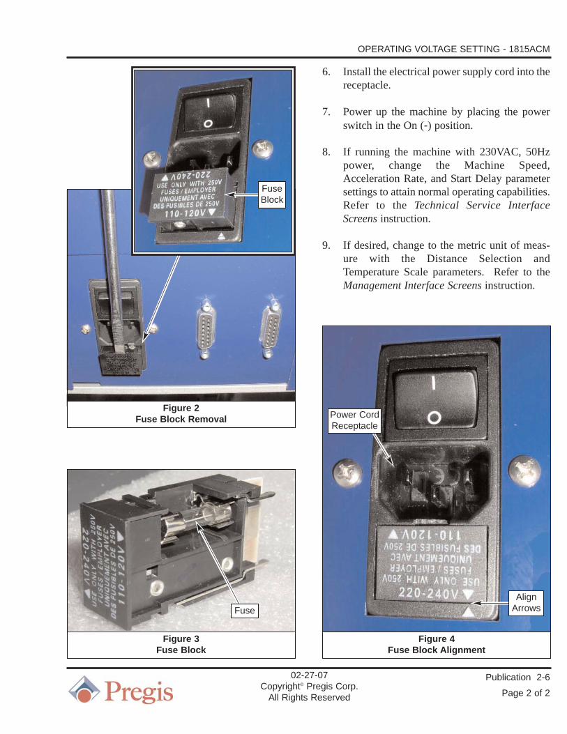
3. Using an appropriate tool, gently pry the fuseblock out slightly from its receptacle. Pull thefuse block completely out of the machine. SeeFigure 2.
4. If changing the machine operating voltagefrom 110-120V to 220-240V, remove the two10A fuses from the fuse block and replacethem with 5A fuses. See Figure 3.
Conversely, if changing the machine operatingvoltage from 220-240V to 110-120V, removethe two 5A fuses from the fuse block andreplace them with 10A fuses.
5. Position the fuse block so that the triangle(arrow) on its edge, that corresponds to thedesired operating voltage, mates with the tri-angle (arrow) on the bottom edge of the recep-tacle. Slide the fuse block into the receptacleand push it in completely until the outer sur-faces are flush. See Figure 4.
Publication 2-6
Page 1 of 2
02-27-07Copyright© Pregis Corp.
All Rights Reserved
Electrical shock or unexpected machinemovement can cause serious injury ordeath. For your safety, follow your compa-ny’s lockout/tagout policy as required foreach task.
OPERATING VOLTAGE SETTINGPREGIS 1815ACMAIR CUSHION MACHINE
Figure 1Switch OFF and Power Supply Disconnected
Applying the incorrect voltage will com-pletly destroy the machine.
PowerSwitch
PowerCord
OPERATING VOLTAGE SETTING - 1815ACM
Publication 2-6
Page 2 of 2
6. Install the electrical power supply cord into thereceptacle.
7. Power up the machine by placing the powerswitch in the On (-) position.
8. If running the machine with 230VAC, 50Hzpower, change the Machine Speed,Acceleration Rate, and Start Delay parametersettings to attain normal operating capabilities.Refer to the Technical Service InterfaceScreens instruction.
9. If desired, change to the metric unit of meas-ure with the Distance Selection andTemperature Scale parameters. Refer to theManagement Interface Screens instruction.
02-27-07Copyright© Pregis Corp.
All Rights Reserved
Figure 3Fuse Block
Fuse
Figure 4Fuse Block Alignment
Power CordReceptacle
Figure 2Fuse Block Removal
FuseBlock
AlignArrows

Introduction
An upper and lower drive belt are each routedaround a guide (tensioning) roller, multiple iders,the sealing drum, and drive pulley. The belts fol-low the same path for about half their lengths, withsurface contact providing a nip section that cap-tures the film. See Figure 1.
NOTE: These belts also provide the drive tounwind the film from the parent roll.
The upper belt wraps the drive pulley that is drivenby an electric gearmotor through a coupling. Thepressure between the two belts is sufficient to drivethe film, contain the air in the cushions, hold thefilm against the sealing drum surface and drive thelower belt.
Publication 3-1
Page 1 of 5
02-12-07Copyright© Pregis Corp.
All Rights Reserved
DRIVE BELT REPLACEMENTPREGIS 1815ACMAIR CUSHION MACHINE
Figure 1Drive Belts
START(green)
JOG(blue)
CoverGuard
Hood
Main Plate
Sealing Drum
Idlers
DrivePulley
Guide(Tensioning)
Roller
Idler
TensionerCapscrews
BeltRouting
Guide(Tensioning)
Roller

DRIVE BELT REPLACEMENT - 1815ACM
Publication 3-1
Page 2 of 5
Expected drive belt life is approximately 1000hours (4500 km), when running film. Belt life willonly be approxiately 100 hours if run in the TestMode, without film. The lower belt will wearfaster than the upper belt due to direct contact withthe heated surface of the sealing drum and from thebelts rubbing together as they wrap around theidlers.
Drive Belt Removal
1. Place the power switch in the OFF positionremove the power cord from the plug. SeeFigure 2.
2. Lift the hood fully, lowering it back onto thecover guard. See Figure 1.
NOTE: Additional access to the drive belts canbe achieved by removing the outfeedcover guard with an Allen™ wrench.
3. At the slots in the main plate, loosen the sock-ethead capscrews that secure the belt tension-ing guide rollers in place. See Figure 1.
4. Push the tensioner handles towards each other,removing tension from the belts. See Figure 3.
02-12-07Copyright© Pregis Corp.
All Rights Reserved
Electrical shock or unexpected machinemovement can cause serious injury ordeath. For your safety, follow your compa-ny’s lockout/tagout policy as required foreach task.
Figure 2Power Removal
Figure 3Belt Tension Release
PowerSwitch
DrivePulley
Guide(Tensioning)
Roller
Guide (Tensioning) Roller
TensionerHandle
TensionerHandle
Power Cord

DRIVE BELT REPLACEMENT - 1815ACM
Publication 3-1
Page 3 of 5
5. First slide both belts off the sealing drumtogether and then continue to remove themfrom the remaining idlers and rollers. SeeFigure 4.
Drive Belt Installation
1. Place the power switch in the OFF positionremove the power cord from the plug. SeeFigure 2.
2. Lift the hood fully, lowering it back onto thecover guard. See Figure 1.
NOTE: A directional arrow is stamped on therough fabric surface of the lower belt.The belt must be installed so the arrowfollows the direction of travel.
3. Install the wider, lower belt around the infeedend lower, flanged guide roller. Place thesmooth, teflon-coated surface of the beltagainst the outside surface of the guide roller.See Figure 5.
NOTE: Additional access to the drive belts canbe achieved by removing the coverguard.
4. Place the belt around the center idlers and seal-ing drum, finishing by placing the belt underthe drive pulley and around the outfeed endidler. See Figure 6.
NOTE: The rough fabric side of the upper beltmust ride against the rough fabric sideof the lower belt.
02-12-07Copyright© Pregis Corp.
All Rights Reserved
Figure 4Belt Removal
Figure 5Lower Belt Routing
Electrical shock or unexpected machinemovement can cause serious injury ordeath. For your safety, follow your compa-ny’s lockout/tagout policy as required foreach task.
Lower Belt
UpperBelt
Lower Belt
Guide(Tensioning)
Roller

DRIVE BELT REPLACEMENT - 1815ACM
Publication 3-1
Page 4 of 5
02-12-07Copyright© Pregis Corp.
All Rights Reserved
Figure 6Lower Belt Routing
Figure 7Upper Belt Routing
Figure 8Upper Belt Routing
SealingDrum
DrivePulley
Center Idlers
SealingDrum
SealingDrum
SealingDrum
Lower Belt
OutfeedEndIdler
Upper Belt
Lower Belt
Upper Idler
Guide (Tensioning) Roller
Center Idlers
UpperBelt
Lower Belt
LowerBelt

DRIVE BELT REPLACEMENT - 1815ACM
Publication 3-1
Page 5 of 5
5. Install the narrower, upper belt around theinfeed end upper, flanged guide roller. Placethe smooth, teflon-coated surface of the beltagainst the outside surface of the guide roller.See Figure 7.
6. Place the belt around the upper idler and cen-ter idlers and sealing drum. Carefully tuck theupper belt into the gap between the lower beltand sealing drum. See Figures 7 and 8.
7. Finish by placing the upper belt under andaround the outfeed end drive pulley. SeeFigure 3.
8. Ensure the edges of both belts are aligned withthe outer edges of the drum and idlers.
9. Pull the upper tensioner handle upward with aspring scale until a reading of 25 lbs. of forceis applied to the belt. Hold the tension on thehandle while tightening the sockethead cap-screw to lock it in place. See Figure 9.
10. Pull the lower tensioning handle downwardwith a spring scale until a reading of 25 lbs. offorce is applied to the belt. Hold the tensionon the handle while tightening the socketheadcapscrew to lock it in place.
11. Once both belts have been properly tensioned,install the power cord and place the powerswitch in the ON position.
12. Close the hood.
13. Press the JOG button to jog the machine toensure that the belts track properly, especiallyaround the drum. See Figure 1. 14. Thread film into the machine and press
START to run briefly to ensure that all aspectsof sealing and drive operate properly. SeeFigure 1.
02-12-07Copyright© Pregis Corp.
All Rights Reserved
Figure 9Upper Belt Tensioning
Guide(Tensioning)
Roller
UpperTensioner
Handle
TensionerCapscrew
SpringScale
Do not try to move the belts while joggingor running. Exposed nip points couldinjure the operator.

Introduction
The drive belts carry the trapped layers of filmaround the sealing drum. The sealing drum con-tains a thin-film heater ring which heats up andcools down quickly. Electric power is supplied tothe heater ring through a slip ring on the inside endof the hollow axle shaft. A sensor within the drumdetects temperature for heater control.
The sealing drum is mounted to the axle shaft bythree sockethead capscrews. Removing thesescrews allows access to the electrical connectionsinside the axle. The heater connection is made witha plug and socket. The sealing drum axle shaft issupported by a pair of bearing housings. The bear-ings do not require lubrication or maintenance.
Drum Removal
1. Place the power switch in the OFF positionand remove the power cord from the plug. SeeFigure 1.
2. Lift the hood fully, lowering it back onto thecover guard. See Figure 2.
3. Loosen the three (3) sockethead capscrewsfrom the face of the sealing drum hub. SeeFigure 2.
4. Remove the upper and lower drive belts.Refer to the Drive Belt Replacement instruc-tion.
5. Remove the three (3) sockethead capscrewsfrom the face of the sealing drum hub. SeeFigure 3.
6. Grip the drum hub and carefully pull it out-ward off the sealing drum axle. See Figure 4.
Publication 3-2
Page 1 of 4
02-12-07Copyright© Pregis Corp.
All Rights Reserved
SEALING DRUM REPLACEMENTPREGIS 1815ACMAIR CUSHION MACHINE
Electrical shock or unexpected machinemovement can cause serious injury ordeath. For your safety, follow your compa-ny’s lockout/tagout policy as required foreach task.
Figure 1Power Removal
PowerSwitch
Power Cord

SEALING DRUM REPLACEMENT - 1815ACM
Publication 3-2
Page 2 of 4
7. Turn the hub over and unplug the electricalconnection on the inside of the hub. SeeFigure 5.
Drum Installation
1. Verify that machine power has been discon-nected and the drive belts have already beenremoved.
02-12-07Copyright© Pregis Corp.
All Rights Reserved
Figure 2Sealing Drum
Figure 3Drum Hub Mounting
Figure 4Sealing Drum Hub Removal
Sealing Drum Hub
Hub
Sealing Drum Hub Sealing Drum Axle
MountingCapscrews
Hood
CoverGuard Electrical shock or unexpected machine
movement can cause serious injury ordeath. For your safety, follow your compa-ny’s lockout/tagout policy as required foreach task.

SEALING DRUM REPLACEMENT - 1815ACM
Publication 3-2
Page 3 of 4
2. Lift the hood fully, lowering it back onto thecover guard. See Figure 2.
3. Plug the electrical connector extending fromthe sealing drum axle into the inside of thedrum hub. See Figures 5 and 6.
4. Carefully tuck the wires into the hollow axleshaft as you insert the drum onto the end of theaxle. See Figure 4.
5. Line up the three holes and install the threesockethead capscrews through the face of thesealing drum hub and into the mating holes inthe end of the axle. Turn capscrews in fully,but do not tighten. See Figure 3.
6. Install the upper and lower drive belts. Referto the Drive Belt Replacement instruction.
NOTE: The drive belts tension is used to holdthe sealing drum hub stationary whilethe mounting screws are tightened.
7. Tighten the mounting capscrews in an alter-nating pattern so that the hub is pulled on theaxle evenly. See Figure 2.
8. Place the power switch in the ON position andinstall the power cord from the plug. SeeFigure 1.
02-12-07Copyright© Pregis Corp.
All Rights Reserved
Figure 5Sealing Drum Electrical Connection
Figure 6Sealing Drum Axle
SealingDrum Hub
Electrical Connection
SealingDrum Axle
HubMounting
HolesSealingDrumAxle

Introduction
The center of gravity of the entire assembly, con-sisting of the cart/stand, film unwind cradle and aircushion machine, is off-center. To steady the entireassembly, the cart’s two infeed end legs, below theunwind cradle, are longer than the two outfeed endlegs. See Figure 1.
The unwind cradle is mounted with two U-bolts toa vertical plate on the stand’s lower support tube.The stand’s upper support tube slides into the lowertube. The upper tube includes the top support platewhere the air cushion machine mounts.
A series of holes are spaced vertically every 2"(51mm) along both the upper and lower supporttubes. The upper tube is raised and lowered in thelower tube, up to 14" (356mm) to set the desiredheight of the air cushion machine.
Once the holes in the upper and lower (inner andouter) support tubes are aligned, a sockethead cap-screw is inserted through the tubes. A lockwasherand nut are placed on the capscrew to secure thetubes in place.
Two sockethead capscrews are threaded into thelower support tube, at 90° to each other, and againstthe upper support tube to eliminate any loosenessbetween the tubes, steadying the air cushionmachine.
Assembly
To assemble the cart/stand, film unwind cradle andair cushion machine:
NOTE: Refer to CMD drawings 153525 and154251 located within the DRAW-INGS section of this manual.
1. Install a caster to the bottom end of each of thefour cart legs using the four buttonhead cap-screws, washers, lockwashers and hexnuts.
Publication 3-3
Page 1 of 3
02-12-07Copyright© CMD Corp.
All Rights Reserved
HEIGHT ADJUSTMENTPREGIS 1815ACMAIR CUSHION MACHINE
Figure 1Air Cushion Machine and Cart/Stand

HEIGHT ADJUSTMENT - 1815ACM
Publication 3-3
Page 2 of 3
2. Install the four cart legs to the bottom side ofthe stand’s lower support plate using two eachsockethead capscrews, lockwashers andhexnuts.
3. Mount the unwind cradle to the tube mountingplate using the four sockethead capscrews.Ensure the plate is positioned with the slottedside facing out.
4. On the stand’s lower support tube, measuredown 7.8" (198mm) from the top and make amark on the tube.
NOTE: The film unwind cradle weighs approx-imately 24 lbs (11 Kg).
5. Set the unwind cradle on top of the infeed end(longer) cart legs with the slotted mountingplate against the tube.
6. Place the two U-bolts around the stand’s lowersupport tube and through the holes in the cra-dle mounting plate. Secure the U-bolts withthe lockwashers and hexnuts. Do not tightenfully. The unwind must still be raised into theoperating position.
7. With the aid of another technician, raise theunwind cradle on the lower support tube untilthe top edge of the upper U-bolt is alignedwith the mark made on the tube in step 4.Tighten the U-bolt hexnuts just enough to holdthe unwind cradle in position on the supporttube. The cradle should still be able to bemoved slightly in the horizontal position.
8. Insert the upper support tube inside the lowersupport tube and allow it to slowly drop to itslowest position.
9. Align the holes in the upper and lower supporttubes and install the sockethead capscrewthrough the tubes. Place the lockwasher and
nut on the capscrew to secure the upper tubefrom rotating. Do not tighten the nut at thistime.
10. Install the two sockethead capscrews into thethreaded holes, 90° from each other, in the out-side of the lower support tube. Do not tightenthe capscrews at this time.
NOTE: The assembled cart/stand weighsapproximately 99 lbs (45 Kg).
11. Remove the lower outfeed guard from insidethe air cushion machine to gain access to themounting holes.
The base plate is L-shaped, with the touchscreenand air pressure regulator mounted to its verticalside. There are four hand holes in the bottom of thebase plate, two on each side, used for lifting the aircushion machine.
NOTE: The air cushion machine weighsapproximately 90 lbs (41 Kg).
12. With the aid of another technician, lift the aircushion machine and place it on top of theupper support plate.
The air cushion machine base plate has a counter-sunk hole, on the outfeed end of the web thread-uplabel, used for position locating. A buttonhead cap-screw is mounted in the cart/stand upper supportplate, directly over the center of the upper supporttube. The capscrew head will fit through the baseplate hole.
13. With the aid of another person, position the aircushion machine so the locator hole in its baseplate fits over the buttonhead capscrew in thecart/stand support plate. Do not tighten thebuttonhead capscrew.
02-12-07Copyright© CMD Corp.
All Rights Reserved

HEIGHT ADJUSTMENT - 1815ACM
Publication 3-3
Page 3 of 3
There are four threaded holes in the upper supportplate for securing the air cushion machine.
14. Hold the cart/stand stationary while slowlyturning the air cushion machine until the fourmounting holes are aligned. Install the foursockethead capscrews through the base plateand into the support plate and tighten.
15. Tighten the buttonhead capscrew in the baseplate.
16. Install the lower outfeed guard inside the aircushion machine.
NOTE: The assembled cart/stand, film unwindcradle and air cushion machine weighsapproximately 213 lbs (97 Kg).
17. Tighten the nut on the sockethead capscrewthat is inserted through the holes in the upperand lower support tubes.
18. Tighten the two sockethead capscrews, 90°from each other, in the outside of the lowersupport tube. This will eliminate any loose-ness between the tubes, steadying the air cush-ion machine.
19. Perform the Alignment procedure within thisinstruction to square the unwind cradle to theair cushion machine.
Alignment
NOTE: Refer to CMD drawings 153525 and154251 located within the DRAW-INGS section of this manual.
This procedure is performed to square the filmunwind cradle to the air cushion machine. Thisensures the web path is straight, preventing a tightor loose film edge, as it enters the air cushionmachine.
NOTE: The straight edge must be long enoughto span the distance between the unwindcradle and the air cushion machine.
The air cushion machine base plate is L-shaped, with the touchscreen and airpressure regulator mounted to its verti-cal side.
1. Place the straight edge against the operatorside of the unwind cradle, as far towards theinfeed end as possible, so that it extendsupward, parallel to the air cushion machinebase plate.
2. Hold the cart/stand stationary while slowlyturning the film unwind cradle in the directionnecessary to achieve a dimension of 0.360"(9.144mm) between the straight edge and theoutside surface of the air cushion machinebase plate.
3. Place the straight edge against the operatorside of the unwind cradle so that it extendsupward, parallel to the air cushion machinebase plate, between the touchscreen and airpressure regulator.
4. Measure the distance between the straightedge and the outside surface of the air cushionmachine base plate. This dimension shouldalso be 0.360" (9.144mm).
5. Once the dimensions are correct and equal,tighten the U-bolt hexnuts to lock the unwindcradle in position.
02-12-07Copyright© CMD Corp.
All Rights Reserved

Daily Maintenance
1. Check the condition of the belts, guide andidler rollers, and drive pulley. Replace thebelts if the splice is peeling or pulling apartmore than 0.03" (0.76 mm).
Weekly Maintenance
1. Clean the belts, belt guide and idler rollers,drive pulley, tow rolls, slitter blade, air pipe,and film idlers of any contamination and/ordebris.
2. Ensure that all parts turn freely, including allbelt idlers, tow rolls, film idlers and parent rollcradle rollers.
3. Ensure the unwind spring-loaded brake strapmechanism works properly.
4. Check that the belt alignment and tracking iscorrect.
Monthly Maintenance
1. Check all components for excessive wear,including the tow rollers and slitter blade.
2. Check fasteners for looseness.
3. Clean the compressor air inlet screen of anydebris.
4. Inspect the sealing surface of the sealing drumfor wear and replace if necessary.
Publication 3-4
Page 1 of 1
02-23-07Copyright© Pregis Corp.
All Rights Reserved
MAINTENANCE SCHEDULE1815ACMAIR CUSHION MACHINE
Electrical shock or unexpected machinemovement can cause serious injury ordeath. For your safety, follow your compa-ny’s lockout/tagout policy as required foreach task.

1. Problem: Machine will not start.
Cause: Machine not set-up properly.
Solution: Turn power ON.
Press RESET button.
Press START button.
Read message at top of screen.Text will read Ready to Run, Paused, or Running.
Thread up film so encoder wheel turns. Machine will not run more than a few seconds if the counter wheel does not turn.
2. Problem: Cushion does not inflate.
Cause: Machine not ready.
Solution: Jogging machine will not start inflation, use START button.
Turn air pressure regulator knob clockwise until the gauge reads 3-8 psi, as required for cushion size being run.
Cause: Insufficient injection air.
Solution: Check if air injector tube is pluggedor disconnected.
Check if air compressor is operating properly.
Cause: Poor quality seal or no seals.
Solution: Refer to Problem 5 Solutions.
Cause: Too much air in cushion blows seals open.
Solution: Reduce the inflation air pressure with the gauged regulator.
3. Problem: Film jams.
Cause: Cushion release slit not being cut properly.
Solution: Clean or replace the slitter blade.
Cause: Film burn through.
Solution: Turn down the sealing temperature.
Cause: Gap in film is too small for air injector tube.
Solution: Replace the roll of film if the gap is not 0.533" ± 0.010".
Cause: Film waste clogging slitter.
Solution: Remove film and waste from knife area.
Cause: Film jamming at tip of slitter knife.
Solution: Position blade so tip is within recess (slot) in air pipe. Blade tip must be below the surface of the air pipe.
Publication 4-1
Page 1 of 2
10-23-06Copyright© Pregis Corp.
All Rights Reserved
TROUBLESHOOTING1815ACMAIR CUSHION MACHINE
Electrical shock or unexpected machinemovement can cause serious injury ordeath. For your safety, follow your compa-ny’s lockout/tagout policy as required foreach task.

TROUBLESHOOTING - 1815ACM
Publication 4-1
Page 2 of 2
4. Problem: No film movement.
Cause: Film is not properly positioned in machine.
Solution: Thread the film as per the thread-up diagram label inside the machine. JOG the leading edge of the film into the belt nip. The film must be taut before pressing START.
Cause: Film slipping.
Solution: Check the film nip idlers and belts for contamination and clean as necessary.
5. Problem: Poor quality seal or no seals.
Cause: Sealing element broken.
Solution: Replace the sealing drum.
NOTE: Allow the seals to cool for approxi-mately one minute before testing.
Cause: Sealing element not hot enough.
Solution: Adjust the sealing temperature.
Cause: Air pressure blowing out seals.
Solution: Decrease the inflation air pressure to prevent overinflating.
Check that the outfeed cooling fanis working properly.
Cause: Film not held tight together between sealing belts.
Solution: Replace worn sealing belts as necessary.
Cause: Surface damage to drum sealing ele-ment, including nicks, cuts or bare aluminum showing through element covering.
Solution: Replace sealing drum.
6. Problem: Main screen “Ready To Run” mes-sage replaced with “Change Belts” message.
Cause: Belt Odometer screen has reached the preset belt change interval value.
Solution: Replace the sealing belt(s) and have Management reset the Actual value on the Belt Odometer screen to zero (0) meters.
NOTE: Refer to the Drive Belt Replacementinstruction for more information.
10-23-06Copyright© Pregis Corp.
All Rights Reserved


![Model No. HC-W585 HC-W585M HC-V385 - Panasonic USA … · HC-W585 [W585] HC-W585M [W585M] HC-V385 [V385] These operating instructions are designed for use with models , and . Pictures](https://static.fdocuments.us/doc/165x107/5f0237ed7e708231d40329d1/model-no-hc-w585-hc-w585m-hc-v385-panasonic-usa-hc-w585-w585-hc-w585m-w585m.jpg)