Safety of rail operations on the interstate rail line ... · Safety of rail operations on the....
104
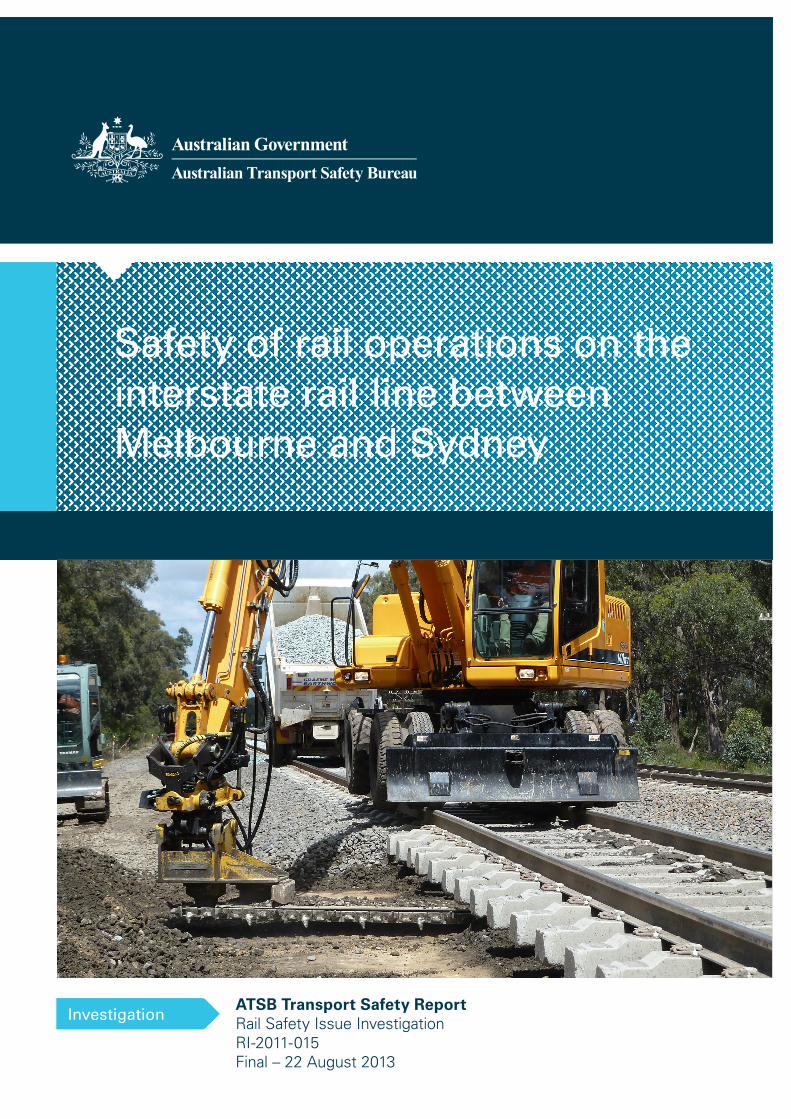
ATSB Transport Safety Report Investigation Safety of rail operations on the interstate rail line between Melbourne and Sydney Investigation ATSB Transport Safety Report Rail Safety Issue Investigation RI-2011-015 Final – 22 August 2013
-
Upload
vuongkhanh -
Category
Documents
-
view
220 -
download
2
Transcript of Safety of rail operations on the interstate rail line ... · Safety of rail operations on the....
Insert document title
Location | Date
ATSB Transport Safety Report[Insert Mode] Occurrence InvestigationXX-YYYY-####Final
Investigation
Safety of rail operations on theinterstate rail line betweenMelbourne and Sydney
InvestigationATSB Transport Safety ReportRail Safety Issue InvestigationRI-2011-015Final – 22 August 2013


Released in accordance with section 25 of the Transport Safety Investigation Act 2003
Publishing information
Published by: Australian Transport Safety Bureau Postal address: PO Box 967, Civic Square ACT 2608 Office: 62 Northbourne Avenue Canberra, Australian Capital Territory 2601 Telephone: 1800 020 616, from overseas +61 2 6257 4150 (24 hours) Accident and incident notification: 1800 011 034 (24 hours) Facsimile: 02 6247 3117, from overseas +61 2 6247 3117 Email: [email protected] Internet: www.atsb.gov.au
© Commonwealth of Australia 2013
Ownership of intellectual property rights in this publication Unless otherwise noted, copyright (and any other intellectual property rights, if any) in this publication is owned by the Commonwealth of Australia.
Creative Commons licence With the exception of the Coat of Arms, ATSB logo, and photos and graphics in which a third party holds copyright, this publication is licensed under a Creative Commons Attribution 3.0 Australia licence.
Creative Commons Attribution 3.0 Australia Licence is a standard form license agreement that allows you to copy, distribute, transmit and adapt this publication provided that you attribute the work.
The ATSB’s preference is that you attribute this publication (and any material sourced from it) using the following wording: Source: Australian Transport Safety Bureau
Copyright in material obtained from other agencies, private individuals or organisations, belongs to those agencies, individuals or organisations. Where you want to use their material you will need to contact them directly

Executive summary In 2007, the Australian Rail Track Corporation (ARTC) embarked on a major investment program to upgrade the rail track between Melbourne and Sydney. Since the program began, there have been a number of incidents and the condition of the line has been subject to significant adverse comment about its safety, largely in relation to rough ride characteristics and the existence and lack of remediation of ‘mud-holes’. On 16 August 2011, the Hon Anthony Albanese MP, Minister for Infrastructure and Transport, requested that the Australian Transport Safety Bureau (ATSB) undertake an investigation to examine (in broad terms) the safety of rail operations on the Melbourne to Sydney line.
In the course of its subsequent investigation, the ATSB found that the track structure between Melbourne and Sydney had historically been particularly vulnerable to degradation in vertical alignment, resulting in poor ride quality and mud-holes. While this was the result of a number of factors, major contributors were the weakness of the track formation (the earthwork foundation on which the track was laid) and ballast fouling (contamination of the aggregate material laid between the formation and the rails and sleepers).
In some locations, this pre-existing vulnerability had been increased by the track upgrade as a result of the process of installing new concrete sleepers. This exacerbated the problems of the pre-existing weak formation and reduced the effectiveness of the ballast. In addition, train forces on a weakened formation, as well as the effects of highly fouled ballast, poor drainage and heavy rainfall during 2010 and 2011, contributed to the development of mud-holes and poor vertical alignment. It is also possible that rail imperfections (localised defects) may have introduced concentrated impact loading that, when transmitted through the sleepers and ballast, may also have overstressed the formation in some locations.
The decisions made by the ARTC about the planning and execution of the upgrade project balanced safety, financial and operational considerations. The ARTC determined that the long term benefits of completely re-sleepering the track between Melbourne and Sydney were high. Safety improvements focused predominantly on controlling track gauge through the installation of concrete sleepers, while financial and operational considerations focused on minimal disruption to rail services and maximum track coverage (sleeper replacement) within financial constraints. The ARTC concluded that this was only possible if the side insertion method of re-sleepering was used and existing ballast was reused as much as possible. The upgrade program proceeded on this basis.
However, the ARTC’s quality assurance process during the project planning phase did not adequately consider foreseeable risks in relation to the track structure’s pre-existing vulnerabilities. It is possible that a more detailed examination of historical information and/or on-site testing may have highlighted any unknown track structure issues and influenced the decisions made prior to the re-sleepering works. Similarly, the ARTC was aware that the existing ballast and track drainage were in poor condition, but appeared not to have adequately considered the potential for higher than normal rainfall following a protracted period of drought. The ARTC believed the drainage problems could be addressed as part of ongoing maintenance programs, but has acknowledged that, following the track upgrade, the rate of track deterioration (including the development of mud-holes) was faster than expected.
During the early stages of the re-sleepering project, the quality control process focused on sleeper spacing, fastening of the rail to new sleepers, clearance of trackside infrastructure and the re-establishment of track geometry, but was inadequate with respect to ballast condition and depth of ballast under the new sleepers. During the course of the project, the procedures were updated based on additional identified risks, including the potential for formation damage due to inadequate ballast depth. The ARTC has since developed more detailed process documentation for side insertion of concrete sleepers. The updated process includes a stronger focus on quality

assurance and recording of quality control data. In general, the ARTC appeared to have a quality assurance process in place that provided for identification of deficiencies, systems review and subsequent improvement to work practices.
It is unlikely that selecting an alternative method of re-sleepering would have prevented deterioration in track condition or the development of mud-holes, unless ballast, drainage and formation issues were also addressed. It is also likely that the cost associated with addressing the ballast, drainage or formation issues would have precluded completely re-sleepering the Melbourne to Sydney line with the funding available and therefore some residual safety risk associated with poor track gauge would have remained if this path had been chosen.
The track deterioration following the re-sleepering works required both short term management and the development of a longer-term major rectification program to maintain the operational effectiveness of the track. For the short term, an increased inspection and maintenance frequency, especially during periods of wet weather, was adopted. Where rail geometry defects were identified, actions were applied as specified by the ARTC (Track & Civil) Code of Practice. Pending rectification, the safety of train operations were maintained largely through the application of speed restrictions. These speed restrictions, together with increased maintenance activities, have resulted in extended train running times along the corridor.
While the application of temporary speed restrictions may in general control the safety risk, the system still relies on prompt identification of track condition hazards before the control measures can be implemented. If the track is performing in a constantly poor and degraded condition, there is an increased risk that defects compromising safety are not immediately identified. In this case, the ARTC have increased the inspection regime to mitigate this risk. However, if the system was performing well, it is likely to be inherently safer since it would place fewer burdens on the defect identification process.
The rail safety regulators in Victoria and New South Wales have, and continue to, actively monitor, audit and inspect the activities of the ARTC with respect to safety on the rail network. Regulatory intervention has resulted in the modification or development of processes aimed at ensuring the safety of rail operations. With the introduction of the Office of the National Rail Safety Regulator, this involvement has continued, but with a more national perspective.
Considering the combination of actions implemented by the ARTC and by the rail safety regulators, the ATSB is satisfied that safety of operations on the Melbourne to Sydney line has been maintained at an appropriate level, albeit with a requirement for greater vigilance to be applied to the inspection of deteriorating track conditions.
Longer term strategies ARTC implemented to rectify persistent problem areas on the line included a combination of undercutting and sledding to address ballast problems (fouling and depth) and track works targeting the correction of general drainage problems. While the treatments applied to date are likely to correct most ballast and drainage problems, the treatments are unlikely to correct the more deep-seated formation problems. Unless additional treatments are applied to improve the formation, it is possible that water will continue to weaken the structure in some locations, with a corresponding requirement for an increased regime of track maintenance (or some localised formation reconstruction) and the application of new or further speed restrictions.
Since the safety of the Melbourne to Sydney line remains dependent on the application of temporary speed restrictions, the ATSB examined the adequacy of the processes for applying such restrictions. The ATSB identified a number of opportunities where operational rail safety could be improved. This was detailed in an Interim Factual Report released in February 2012. The ARTC advised of their proposed actions in response and the ATSB is satisfied that those actions addressed the issues that were identified.
Both the initial upgrade and the subsequent rectification program led to a significant amount of track work being conducted on the Melbourne to Sydney line. This increased the likelihood of safeworking incidents involving track maintenance activities. The ATSB examined a number of
reported safeworking incidents that occurred at various times between 2009 and 2012 and found that, in general, the safeworking rules and procedures were adequate as long as they were complied with. However, some of the incidents highlighted that protection methods for work on track were susceptible to human error, either through mistake or violation. In some cases, the safeworking systems were vulnerable to a ‘single point of failure’ which could increase the risk to rail safety. The ARTC, in consultation with rail safety regulators, has implemented changes to their systems for safely managing work on track and help protect against human error.
During the course of the investigation, rail operators also raised a number of specific concerns about the safety of the Melbourne to Sydney rail line. These related to elements of the signalling system, train parting incidents and quality assurance of track-related work. For signalling, the ATSB found that the principles applied to signalling design and the process for assessing signal sighting issues were consistent with recognised acceptable practice. For train partings, the ATSB found that track condition was a factor but not always the sole issue. Where deficiencies were identified, the ARTC issued additional instructions aimed at ensuring the safety of rail operations.
Taken as a whole, the ATSB is satisfied that the necessary steps have been taken to address any issues that might otherwise compromise the safety of rail operations where track quality is below acceptable operational standards. However, the actions taken to ensure safe operations have come at the expense of operational efficiencies through increased train running times.

Contents
Introduction ..............................................................................................................................1 Background 1
Infrastructure management ...................................................................................................3 Track structure - description 3 Inspection and Maintenance 5 Repair, rehabilitation and upgrade 9 Economics and safety 10
Track condition ..................................................................................................................... 13 Incident data 15 Speed restrictions 20 Track quality index (TQI) 21 Summary of track condition 27
Track condition and safety.................................................................................................. 28 Temporary speed restrictions (TSR) 28 Short term remediation work 29
Short term treatments 30 Rail safety regulation 31 Summary of track condition and safety 32
Factors affecting track condition ....................................................................................... 34 Load distribution 34 Method of sleeper replacement 37 Drainage 42 Environmental conditions 46 Summary of factors affecting track condition 50
Long term remediation work ............................................................................................... 52 Limitations to remediation works 53 Summary of remediation work 54
Safeworking – Work on track .............................................................................................. 55 Signal blocking facilities 55
Summary of signal blocking facilities 56 Joint occupancy TOAs (New South Wales) 57
Summary of joint occupancy TOAs 58 Working outside the limits of authority 58
Summary of working outside the limits of authority 58 Miscellaneous safeworking incidents 59
Summary of miscellaneous safeworking incidents 59 Summary – Safeworking practices 59
Systemic review of safety systems ................................................................................... 61 Signalling system 61
Signal sighting 63 Summary – Signalling system 70
Train control reports 70 Actions taken by the ARTC 71 Summary – Train control reports 71
Train parting incidents 71 Summary - Train parting incidents 73
Quality assurance of work undertaken on the track 74 Actions taken by the ARTC 76 Summary - Quality assurance of work undertaken on the track 76
Actions taken to improve safety ........................................................................................ 78
Findings ................................................................................................................................. 81 Context 81
Condition of the interstate rail track and safety of rail operations 81 Actions to remediate the track 83 Safeworking practices 83 Systemic review of safety systems 84
Appendix A – Temporary speed restrictions .................................................................... 85 Application of temporary speed restrictions 85 Operator imposed speed restrictions 90
Sources and submissions .................................................................................................. 92 Sources of information 92 References 92 Submissions 93
Australian Transport Safety Bureau .................................................................................. 94 Purpose of safety investigations 94 Developing safety action 94
› 1 ‹
ATSB – RI-2011-015
Introduction On 16 August 2011, the Hon Anthony Albanese MP, Minister for Infrastructure and Transport, requested that the Australian Transport Safety Bureau (ATSB) undertake a systemic investigation of rail operations on the interstate rail line between Melbourne and Sydney. In particular, the ATSB was requested to examine:
• The condition of the interstate rail track and measures that have been put in place to maintain the safety of rail operations where track quality is below acceptable operational standards (see sections titled Track condition and Track condition and safety);
• Actions taken by the Australian Rail Track Corporation (ARTC) to remediate the track and address the safety of operations (see sections titled Factors affecting track condition and Long term remediation work);
• Safeworking practices in relation to the track (see section titled Safeworking – Work on track); • A systemic review of safety systems; including signalling and the quality assurance of work
undertaken on the track (see section titled Systemic review of safety systems); and, • Any other matters considered relevant by the ATSB. The ATSB agreed to the Minister’s request and commenced an investigation. The following report of the investigation has been structured so that the main sections directly reflect and address the Minister’s terms of reference.
Background The track between Melbourne and Sydney is part of the defined interstate rail network and is managed by the Australian Rail Track Corporation (ARTC) under long term lease arrangements with the state governments in Victoria and New South Wales. The lease arrangement for the line in Victoria (Melbourne to Albury) commenced in 1998. In New South Wales, the lease arrangement commenced in 2004 for the line between Albury and Macarthur (outer metropolitan Sydney).
As part of the lease agreements the ARTC is responsible for infrastructure maintenance, network control and management of track access by train operators primarily moving freight (such as Pacific National and Aurizon) but with some intercity and regional passenger operators (such as V/Line, RailCorp/CountryLink1). In addition, the lease agreements include a commitment to undertake a program of infrastructure improvement to both track and signalling.
At the time of the investigation2, New South Wales and Victoria each had an independent rail safety regulator3 responsible for administering the requirements of their respective rail safety legislation. The track between Melbourne and Sydney is part of the defined interstate rail network, so rail safety investigations are usually conducted by the ATSB. However, both New South Wales and Victoria also have independent investigation agencies4 responsible for conducting no-blame investigations of rail safety matters.
The ARTC, since commencing a program of capacity enhancement, signalling modernisation and track upgrading on the Sydney to Melbourne line, has been subject to significant adverse comment, largely in relation to the existence and remediation of ‘mud-holes’. There have also been a number of incidents on the corridor, including the parting of an interstate passenger train 1 During the investigation RailCorp was restructured to become Sydney Trains and NSW Trains which both commenced
operations on 1 July 2013. NSW Trains now operates the rail passenger services on the Melbourne – Sydney line. 2 Since the investigation was completed, there has been a progressive transition to a single national arrangement for rail
safety regulation and investigation. 3 The Independent Transport Safety Regulator (New South Wales) and Transport Safety Victoria 4 The Office of Transport Safety Investigations (New South Wales), the Chief Investigator Transport Safety (Victoria)
› 2 ‹
ATSB – RI-2011-015
near Broadmeadows, Victoria on 11 August 20115 and the routing of a train onto the wrong railway track near Seymour, Victoria on 25 July 20116. The ongoing comments regarding mud-holes and the incidents associated with rail safety gave rise to questions regarding the management and operational safety of the line. Consistent with the Minister’s request, this report explores the ARTC’s system of infrastructure management with a focus on the condition of track between Melbourne and Sydney, the factors that may have affected the condition of the track and measures put in place to maintain the safety of rail operations. In addition, the report explores the actions taken by the ARTC to remediate the track from Melbourne to Sydney and the associated safeworking practices.
The ATSB sourced information and data from various organisations, regulators and some individuals. The majority of data was requested at the commencement of the investigation and subsequently received by October 2011. Preliminary examination of information found that reliable and consistent data was only available after 2007. Consequently, the analysis of data and discussion relating to track condition is limited to the period between January 2007 and October 2011.
5 ATSB reference RO-2011-012 6 Chief Investigator, Transport Safety reference 2011/08

› 3 ‹
ATSB – RI-2011-015
Infrastructure management This section is a brief overview of infrastructure management to provide a base understanding and context to the following discussion on track condition, safety and factors that can affect track condition.
Modern infrastructure management encompasses a ‘cradle to grave’ concept that embodies all stages of a product’s life-cycle i.e. design, construction, manufacture, operations, repair/maintenance and finally disposal. A critical component of this process is determining the cost effective balance between initial asset functionality and the ongoing maintenance task and to ensure that the asset (the track in this case) is safe and fit for purpose.
For rail track, the life-cycle process aims to create an infrastructure system that conforms to appropriate safety standards and is compatible with functional and operational needs. Nevertheless, track and civil infrastructure is a system of components which deteriorate in condition through a number of factors including usage and aging. It is the role of the inspection and maintenance process to ensure that the infrastructure condition stays within the designed operational limits. Each step has an economic cost and benefit that must be balanced to ensure the ongoing viability of operations.
Track structure - description The structure of a rail track consists of a number of components, including the rail, sleepers, ballast and the formation. The formation is the earthworks structure upon which the ballast is laid and usually consists of the sub-grade (earth fill on top of the natural earth) and a capping layer (compacted material that provides a sealing layer to the sub-grade). The main purpose of the formation is to provide a consistent level surface at the required height above the natural ground (Figure 1).
Figure 1: Track structure
Source: ATSB
The main function of the rail, sleepers and ballast is to transfer the train load to the formation by progressively distributing the load over an ever increasing area. For example, a train exerts a large force onto a small wheel/rail contact area. The load is then transferred through the foot of the rail (larger area) and onto the sleeper. The long sleeper transfers the load onto the ballast bed, which in turn transfers the load to the formation (Figure 2). In each step, the vertical stress (force per unit area) becomes progressively less. Each component of the track structure is selected based on its ability to accommodate different levels of stress without harmful deformation. The main design parameters determining the magnitude of expected stress are related to track speed and axle load, which affect both dynamic and static loads.

› 4 ‹
ATSB – RI-2011-015
Figure 2: Distribution of wheel load
Note: The load distribution of only one sleeper is shown. Source: ATSB
The rail is the first element to support the train load and must be rated such that it can support both dynamic and static loads without excessive bending stresses. As the requirements for axle loads and track speed increase, so does the sectional size of the rail. Rail is described in terms of mass per unit length (kg/m or lb/yard). The method of fastening the rail to the sleepers is important to ensure the rail is secure, to assist transfer of the load and to resist longitudinal and lateral movement of the rail with changes in temperature and train induced forces.
The primary purpose of the sleeper is to locate and support the rail and maintain suitable track geometry under vertical, lateral and longitudinal loads. The most common sleeper materials used for mainline operations are timber, concrete, and steel.
The main function of the ballast is to distribute the loads to a suitable formation while providing the necessary support to maintain correct track geometry. The ballast bed must also provide adequate drainage to ensure water is not retained within the track structure. Ballast is usually obtained from quarried rock and must have suitable properties to interlock and distribute load (angularity) while also being resistant to crushing and breakdown.
Track infrastructure is designed and constructed to ensure it meets defined operational and whole of life requirements, but design decisions are invariably linked to economic constraints. In many cases, therefore, the infrastructure may not have the capacity to accommodate future changes to operational requirements. If, over the life of the infrastructure, the operational requirements change and the existing design cannot accommodate the new requirements, then the infrastructure will need replacement or upgrading to the new design parameters.
› 5 ‹
ATSB – RI-2011-015
Track structure – Melbourne to Sydney
Most rail lines in Australia were constructed many years ago, in some States as early as the mid-1850s. The line between Melbourne and the New South Wales border (Wodonga) was originally constructed in the late 1870s as a broad gauge (1600 mm) track. The link between Sydney and the Victorian border was completed by 1881, although the standard track gauge (1435 mm) was adopted. When the two rail lines were originally designed and constructed, rail traffic was lighter, slower and with annual gross tonnages significantly less than today’s traffic. The design criteria were developed for the conditions of the day and were not necessarily consistent with the current operational requirements and design standards.
For example, information provided to the ATSB regarding the original construction of the track in Victoria suggests that formation and ballast material was sourced from surrounding and local areas. In many cases, the material used for the formation, capping and ballast would not be considered suitable by current standards. The rail was 94lb/yard (47 kg/m) in 27 m (90 foot) lengths, joined using 4-hole fishplates and dog-spiked to timber sleepers at a spacing of 685 mm (about 1460 per kilometre). The ballast depth below the sleepers was about 150 mm.
It was not until 1962 that an additional standard gauge track (following the existing broad gauge alignment) was completed in Victoria, allowing a continuous link between Melbourne and Sydney. Soon after the line was opened, mud-holes, geometry defects and broken fishplates began to occur, resulting in a number of derailments. A program was implemented to replace the 4-hole fishplates with stronger 6-hole fishplates, but the problem continued until the 1970s and 80s, by which time the rail joints had been welded to create Continuous Welded Rail (CWR).
While the track had undergone various changes and upgrades over the years, at the time when the ARTC took control of the interstate rail lines in Victoria (1998) and New South Wales (2004), the structure was still not consistent with the desired operational requirements (axle loading and track speed) and design standards. The current standard for mainline track construction calls for 60 kg/m CWR, supported on timber or concrete sleepers (600 mm and 667 mm spacing respectively) with a minimum of 250 mm ballast below each sleeper.
Inspection and Maintenance Infrastructure deteriorates over time as the result of use and climatic and other conditions. Inspection and maintenance is the process of ensuring infrastructure condition stays at or above a defined limit or state, appropriate for the operating requirements. The process is based on a regime of inspection to detect defects, assessment to determine the required response and corrective action to repair the defect.
Maintenance Model
The maintenance model is based on a philosophy of ensuring a deteriorating infrastructure system is maintained to a condition above a defined minimum standard. A simple description of the model is a ‘Condition’ versus ‘Time’ graph that describes the life cycle phases of infrastructure condition. Figure 3 illustrates a simplified version of the maintenance model described in the Australian Standard Rail Networks Code of Practice7, based on fixed operational requirements.
7 RISSB, Australian Standard Rail Networks Code of Practice – Volume 4 – Track, Civil and Electrical Infrastructure –
Part 1: Infrastructure Management

› 6 ‹
ATSB – RI-2011-015
Figure 3: Infrastructure Maintenance Model
Source: ATSB
The model incorporates the following attributes:
• The ‘Design’ line represents the theoretical condition level to which the infrastructure has been designed.
• The ‘Construction’ line represents the actual condition level to which the infrastructure was originally built.
• The ‘Maintenance’ line represents the condition level that the infrastructure is returned to following maintenance to corrected defects.
• The ‘Base Operating Standard’ line represents the condition level below which the risk of failure is unacceptable.
• The ‘Failure’ line represents the condition level at which if operated on, will probably result in failure.
Throughout the asset life-cycle, infrastructure progressively deteriorates over time. Operational experience will generally enable determination of maximum and minimum deterioration rates (note that the deterioration rate may not be linear as depicted in Figure 3). It is the role of the infrastructure maintainer to implement a cost-effective maintenance regime to ensure the condition level is periodically returned to an acceptable level that exceeds the ‘Base Operating Standard’ and preferably approaches the ‘Maintenance’ line. If infrastructure is not maintained effectively it will deteriorate with a risk of failure.
The concept not depicted in the simplified maintenance model relates to a change in operational requirements. The lines in the model can be influenced by a change in operational parameters such as axle load and track speed. For example, if the track is to accommodate higher axle loads and/or track speeds, the track condition would almost certainly need to be maintained to a higher Base Operating Standard. If the track cannot be maintained effectively and consistently degrades to the Base Operating Standard, an upgraded design would need to be considered.
Conversely, if track condition deteriorates to a level below the Base Operating Standard, then a change may be required to the operating requirements to manage the risk of failure. For example,

› 7 ‹
ATSB – RI-2011-015
axle loads and/or track speed could be reduced to ensure safe operation over the deteriorated track condition.
Inspection and maintenance – Melbourne to Sydney track
Up until 15 November 2011, the ARTC inspection, assessment and maintenance standards were different in New South Wales and Victoria8. In Victoria, the standards were drawn down from the Rail Industry Safety and Standards Board (RISSB) Code of Practice-Volume 4, Track and Civil Infrastructure. In New South Wales, the standards and procedures were distributed over multiple documents inherited from the Rail Infrastructure Corporation (which no longer exists as an organisation).
Since taking control of the interstate rail lines in Victoria (1998) and New South Wales (2004), the ARTC has progressively integrated the State based rules and procedures with the aim of developing common standards across the entire ARTC rail network; the ARTC (Track & Civil) Code of Practice. From 15 November 2011, common standards for inspection, assessment and maintenance were adopted for both States and documented in Section 5, Track Geometry of the ARTC Engineering (Track & Civil) Code of Practice. The revised code of practice continued to adopt an approach similar to the previous standards, but consolidated the detail into a single document9 & 10. The document specifies both the standards for inspection/assessment and the appropriate action to be taken for defined defects.
Track inspection is the process by which the track condition is monitored to identify possible defects that may affect, or have the potential to affect, the capability of the infrastructure to safely perform its required function. The inspection process consists of two complementary inspection types:
• Scheduled inspections – the primary tool for ensuring infrastructure is maintained to a level that is both safe and appropriate for the intended purpose. The ARTC code of practice provides for the following types of scheduled inspection. - Track patrols
Track patrols are usually conducted as a visual inspection while travelling the track in a road-rail vehicle11. The ARTC code of practice states that track patrols must be scheduled at intervals not exceeding seven calendar days.
- Front of train inspections Front of train inspections are visual inspections of the track and an assessment of ride performance while travelling in the driver’s cab of a train. The ARTC code of practice states that front of train inspections are to be scheduled at intervals not exceeding six months.
- Track geometry car12 The track geometry car is a locomotive-hauled automated track inspection vehicle used to measure several geometric track parameters without obstructing normal railroad operations. The ARTC code of practice states that track geometry car inspections are to be scheduled at intervals not exceeding four months.
8 The difference between States is a legacy of rail operations in Australia developing as State based organisations, each
with their own rules and procedures. 9 This report examines the inspection, assessment and maintenance process with reference to the ARTC’s consolidated
code of practice. Specific aspects of the obsolete documentation will be referenced where required. 10 The process of developing common standards across the entire ARTC rail network is ongoing. Consequently,
standards that are still specific to a particular State will be referenced as required. 11 A road vehicle fitted with retractable rail guidance wheels. (Source: National Guideline Glossary of Railway
Terminology, www.rissb.com.au) 12 A locomotive hauled rail vehicle with electronic track recording equipment.

› 8 ‹
ATSB – RI-2011-015
- Ultrasonic Testing A specialised track inspection vehicle that uses ultrasonics to test for defects in the rail.
• Unscheduled inspections – usually occur in response to defined events. For example, extreme weather conditions can cause track damage (debris on the track or washaway of the formation), so an unscheduled inspection is usually conducted immediately after such an event and before trains travel the section. A more common trigger for an unscheduled inspection is third-party track condition reporting. Train drivers are continuously travelling the track, so are an essential source of information regarding track conditions that may affect rail operations, such as rough ride quality.
As part of the process in determining track condition, a series of track geometry parameters such as vertical and horizontal alignment, cross level variation, twist and gauge are considered. Potential track defects are examined and their severity determined with reference to defined defect limits for each track geometry parameter. The defined limits are documented in the ARTC code of practice.
The track geometry car accurately measures the track and compares the results against a table of defect limits, which allows an appropriate response category to be allocated based also on rated track speed. Personnel conducting track patrols and unscheduled inspections do not normally take measurements, but assess the severity of potential defects based on their knowledge and experience. While measurements may not always be taken, an appropriate response category is still allocated with reference to the table of defect limits, but based on rated track speed and an estimate of the defect size.
Each method of inspection has both advantages and disadvantages, but combined the inspection methods provide an effective process for identifying potential maintenance issues with the track. For example, track patrols can be conducted at short notice whereas inspection using the track geometry car must be planned in advance. Track patrols are usually carried out using a relatively light weight road-rail vehicle which does not cause significant track deflection. Consequently, potential geometry defects may not be identified because the patrol did not detect any significant deflection while travelling along the track, even though fouled ballast (ballast contaminated or fouled with fine materials) may be visible. Front of train and track geometry car inspections address this limitation by exposing track geometry defects under load conditions.
Track maintenance is the process whereby action is taken to ensure the track structure is maintained to a condition appropriate for safe and continued operation of rail traffic. Where track geometry defects are identified, immediate action is taken to rectify the problem or else operational limitations are applied (such as speed restrictions) to ensure safe passage of rail traffic until the defect can be repaired. Based on the assessment of track geometry defects, the action to be taken to control any risk to railway operational safety is defined by a series of response codes (Table 1: Definition of response codes).
Since response categories are based on defect size and track speed, it is possible to reduce the priority of a response by applying a speed reduction over the defective section of track. The inspection regime for the reduced category would then apply for assessing any deterioration of the defect. If there is no change to the defect, then reinspections continue until the defect is repaired. If the defect deteriorates further, then it is again categorised and a further ‘Temporary Speed Restriction’ (TSR) may be applied subject to the revised category. The process continues until the defect is repaired (refer to the section titled ‘Track condition’ which describes the condition of the track between Melbourne and Sydney, and the section titled ‘Track condition and safety’ which describes how the maintenance processes were applied).
› 9 ‹
ATSB – RI-2011-015
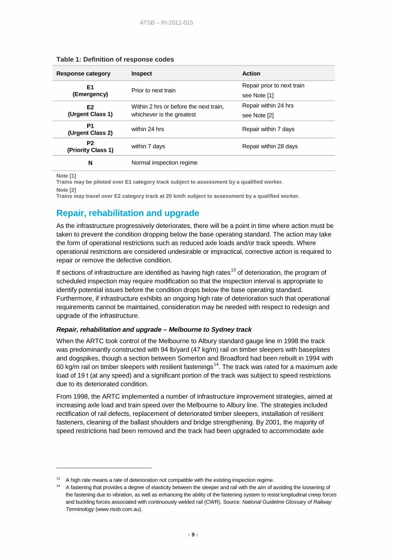
Table 1: Definition of response codes
Response category Inspect Action
E1 (Emergency) Prior to next train
Repair prior to next train see Note [1]
E2 (Urgent Class 1)
Within 2 hrs or before the next train, whichever is the greatest
Repair within 24 hrs see Note [2]
P1 (Urgent Class 2) within 24 hrs Repair within 7 days
P2 (Priority Class 1) within 7 days Repair within 28 days
N Normal inspection regime
Note [1] Trains may be piloted over E1 category track subject to assessment by a qualified worker. Note [2] Trains may travel over E2 category track at 20 km/h subject to assessment by a qualified worker.
Repair, rehabilitation and upgrade As the infrastructure progressively deteriorates, there will be a point in time where action must be taken to prevent the condition dropping below the base operating standard. The action may take the form of operational restrictions such as reduced axle loads and/or track speeds. Where operational restrictions are considered undesirable or impractical, corrective action is required to repair or remove the defective condition.
If sections of infrastructure are identified as having high rates13 of deterioration, the program of scheduled inspection may require modification so that the inspection interval is appropriate to identify potential issues before the condition drops below the base operating standard. Furthermore, if infrastructure exhibits an ongoing high rate of deterioration such that operational requirements cannot be maintained, consideration may be needed with respect to redesign and upgrade of the infrastructure.
Repair, rehabilitation and upgrade – Melbourne to Sydney track
When the ARTC took control of the Melbourne to Albury standard gauge line in 1998 the track was predominantly constructed with 94 lb/yard (47 kg/m) rail on timber sleepers with baseplates and dogspikes, though a section between Somerton and Broadford had been rebuilt in 1994 with 60 kg/m rail on timber sleepers with resilient fastenings14. The track was rated for a maximum axle load of 19 t (at any speed) and a significant portion of the track was subject to speed restrictions due to its deteriorated condition.
From 1998, the ARTC implemented a number of infrastructure improvement strategies, aimed at increasing axle load and train speed over the Melbourne to Albury line. The strategies included rectification of rail defects, replacement of deteriorated timber sleepers, installation of resilient fasteners, cleaning of the ballast shoulders and bridge strengthening. By 2001, the majority of speed restrictions had been removed and the track had been upgraded to accommodate axle
13 A high rate means a rate of deterioration not compatible with the existing inspection regime. 14 A fastening that provides a degree of elasticity between the sleeper and rail with the aim of avoiding the loosening of
the fastening due to vibration, as well as enhancing the ability of the fastening system to resist longitudinal creep forces and buckling forces associated with continuously welded rail (CWR). Source: National Guideline Glossary of Railway Terminology (www.rissb.com.au).

› 10 ‹
ATSB – RI-2011-015
loads of 20 t at 115 km/h, 21 t at 110 km/h and 23 t at 80 km/h. While improvements had been made, the track structure was still below the current standard for newly constructed track15.
In 2004 when ARTC took control of the track between Albury and Sydney it consisted of 107 lb/yard (53 kg/m) or 60 kg/m rail supported by sections of concrete sleepers or timber sleepers interspersed with both steel and low profile concrete sleepers. The consequence was a high number of track geometry defects and a significant number of speed restrictions16.
From 2004 onward, the ARTC implemented strategies aimed at improving the transit times and network capacity over the Albury to Sydney line in New South Wales. These included correcting the problems arising from interspersed steel sleepers and the removal of a number of speed restrictions. In addition, the ARTC improved the signalling systems and crossing loops and replaced the Murrumbidgee Bridge at Wagga Wagga.
In 2007 the ARTC embarked on a major investment program (North South Corridor Strategy) to further upgrade the track between Melbourne and Sydney. The investment program was largely funded by the Commonwealth and included the replacement of the existing timber and steel sleepers in the line with new concrete sleepers. Also, in 2008 the broad gauge track from Melbourne to Wodonga was included in the ARTC lease allowing the track to be converted to standard gauge and upgraded to permit increased axle loads and train speeds.
By 2011, the track between Melbourne and Sydney had generally been brought up to the current design standards with respect to rail and sleepers but there was insufficient funding to upgrade the formation and much of the original ballast was reused17.
Economics and safety Economics and safety are inherently linked at each step of the infrastructure management process. For example:
• Design and construction Current and predicted operational requirements will influence decisions made during design and construction, which in turn will influence deterioration rates and therefore the required inspection and maintenance regime.
• Inspection and maintenance Economic factors may influence a decision to apply corrective actions at a level above the base operating standard. That is, preventative maintenance philosophies may be applied.
• Repair, rehabilitation and upgrade The decision to repair, rehabilitate or upgrade would likely be based on economic grounds, especially where large costs are involved or where work is likely to cause service interruptions.
The ARTC was established in July 1998 after the Commonwealth and State Governments had agreed to create a ‘one-stop-shop’ responsible for managing the interstate rail network, including the coordination of investment strategies, maintenance and managing access to the rail network.
The ARTC was established as a commercial entity with the Commonwealth as its primary shareholder. Consequently, the ARTC is funded through the receipt of access fees, and not recurrent Government funding as would be expected with a Government Department. Nonetheless, the Commonwealth does provide capital investment for specific projects, from which 15 The base standard for newly constructed mainline track specifies 60 kg/m continuously welded rail, fixed to concrete
sleepers with resilient fasteners and supported on a bed of ballast with a depth of 250 mm under the sleepers. 16 OTSI Rail Safety Investigation Report – Steel Sleeper Introduction on NSW Class 1 Main Line Track 1996-2004 found
that the installation of the steel and low profile concrete sleepers had contravened both the engineering standards of the time and, with respect to steel sleepers, the manufacturer’s installation guidelines.
17 Formation and ballast standards are discussed in the section titled ‘Factors affecting track condition’.

› 11 ‹
ATSB – RI-2011-015
it expects a commercial return, usually in the form of economic growth through improved interstate rail infrastructure.
Considering the commercial nature of the ARTC, it is evident that economics plays an important role in the decisions made when investing capital funds. For example, an injection of funding is directed to projects that are likely to provide an economic advantage through improved rail services between capital cities and ports. At the same time, steps taken to ensure safety of rail operations can also affect the efficiency and economics of the interstate rail network.
Economics and safety – Melbourne to Sydney track
Since mid-2010 the condition of the track on sections of the Melbourne to Sydney line has been the subject of significant adverse comment. While the comments mainly focussed on track condition (discussed in the next section, titled Track condition) there was also criticism directed at the methods chosen for track repair, rehabilitation and upgrade of the Melbourne to Sydney line.
Prior to 2004, the ARTC only held control of the Victorian section of the Melbourne to Sydney line. While the ARTC invested in strategies to rectify defects and remove speed restrictions, it could do little to improve the economics of the Melbourne to Sydney line because it had no influence over the New South Wales section of track. After taking up the lease of the New South Wales section of track (2004), the ARTC could then target investment for the economic benefit of rail operations for the whole of the Melbourne and Sydney rail link. The lease agreement incorporated an investment of funds that focused mostly on the introduction of remote controlled signalling to replace manual signal boxes, additional crossing/passing opportunities and some improvement to track infrastructure. In 2006, the Commonwealth provided additional funding which allowed the ARTC to also consider the installation of concrete sleepers from Melbourne to Sydney.
Concrete sleepers have a number of advantages, such as improved track stability through additional weight, long service life and ease of manufacture/availability. In addition, concrete sleepers are very effective in holding the track to gauge, a significant control measure against spread-gauge derailments. Timber, on the other hand, is susceptible to weathering, biological attack and progressive loosening of the rail fasteners.
Between Melbourne and Sydney, the condition of the existing timber sleepers dictated that replacement was required over much of the line. The ARTC perceived a difficulty in obtaining sufficient, good quality timber sleepers to safely maintain the network, whereas concrete sleepers could be readily sourced. Concrete sleepers were also considered to have better resistance to misalignment during hot weather, especially where ballast quality may have been an issue. In addition, the ARTC considered a complete replacement using concrete would reduce operational delays in the long term, since the requirement for track access to do maintenance is less for concrete than timber. Overall, the long term economic benefits of concrete were considered attractive.
Funding was limited, so the ARTC had to make a decision as to the best use of funds with respect to both the extent and the method of re-sleepering (refer to the section titled ‘Method of sleeper replacement’ for a description of the available re-sleepering methods). The ARTC facilitated a number of workshops with its alliance contractors18 and it became clear that using an automated track laying machine was essential on the North Coast line (north of Newcastle) due to tight track curvature and difficulty or a complete lack of access to distribute sleepers for side insertion. Sleeper replacement works on the North Coast line had started before the line south to Melbourne, so the ARTC had gained experience with respect to unit cost, track access and potential disruption that works could have on rail operations.
18 Alliances are contracts in which all parties agree to work as an integrated team and are bound by a shared risk/reward
scheme which is dependent on the success (or otherwise) of a specific project.
› 12 ‹
ATSB – RI-2011-015
When considering the program of works between Melbourne and Sydney, the ARTC and its alliance contractors determined that financial limitations and unacceptable disruption to rail operations precluded the use of the track laying machine. The ARTC and its alliance contractors concluded that it was only possible to completely re-sleeper the Melbourne to Sydney line with concrete sleepers (within financial and operational limitations) if:
• A sleeper spacing of 667 mm (1500 sleepers per kilometre) was adopted19
• The side insertion method was used20
• Minimal additional ballast was required.
The basis of the decision, given the funding constraints, was to achieve minimum cost of materials and installation with minimum disruption to train operations. The ARTC was aware that existing poor ballast condition would require additional work, which it believed could be done as part of its ongoing maintenance programs. The ARTC and its contractors considered that the economic and safety benefits (long term cost, track stability and control of track gauge) associated with installing concrete sleepers to the entire track between Melbourne and Sydney outweighed the disadvantage of retaining sections of timber (or steel) sleepered track.
19 ARTC (Track & Civil) Code of Practice states that 667mm sleeper spacing is permitted for tracks carrying axle loads not
exceeding 25 tonne. Spacing of 667 mm had been successfully adopted in other locations on the ARTC network and was known to achieve acceptable ballast pressure and strength requirements.
20 The side insertion method involves removing existing sleepers and inserting new sleepers from the side of the track without the need to remove the rail.

› 13 ‹
ATSB – RI-2011-015
Track condition This section examines various sources of evidence with respect to the condition of the track between Melbourne and Sydney, and to determine what elements of the track structure may have exhibited conditions that were below acceptable operational standards.
The track between Melbourne and Sydney had long been known to be in poor condition (to various degrees). The ARTC adopted various strategies to improve track condition, including the reallocation of funds to the areas identified as exhibiting the greatest safety risk. While improvements were made, the track between Melbourne and Sydney continued to exhibit poor geometry and attract reports of rough riding from train drivers.
More intense public scrutiny developed through 2010 with comments often citing the method of sleeper replacement as the initiator of the problems, but evidence would suggest that a degradation of track condition existed (to various degrees) well before this intense public scrutiny. For example, in July 2008, a freight train derailed near Winton, Victoria21. The investigation found that a track condition contributed in part to the derailment. Figure 4 illustrates a section of track near Winton in 2008. The track to the left was the original broad gauge line (which was non-operational at the time of the photograph and later converted to standard gauge) and the track to the right was the standard gauge main line. Similar to more recent times, the area had been the subject of rough-riding reports, though it is evident that the track was yet to be upgraded with concrete sleepers. The wavy track geometry of both lines is typical of underlying structural problems.
Figure 4: Poor track geometry
Note: The angle and magnification of the photograph provides an exaggerated view of the track geometry
defects Source: ATSB
Many of the more recent adverse comments were related to rough riding and mud-holes. A mud-hole is a generic term used to describe a condition where the sleepers appear to be surrounded by mud rather than ballast. Mud-holes occur when the ballast becomes contaminated (or fouled)
21 ATSB report RO-2008-009
› 14 ‹
ATSB – RI-2011-015
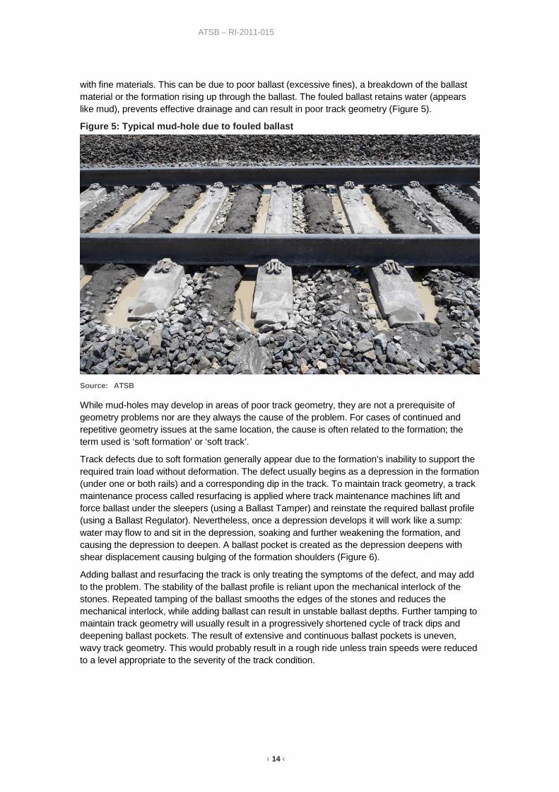
with fine materials. This can be due to poor ballast (excessive fines), a breakdown of the ballast material or the formation rising up through the ballast. The fouled ballast retains water (appears like mud), prevents effective drainage and can result in poor track geometry (Figure 5).
Figure 5: Typical mud-hole due to fouled ballast
Source: ATSB
While mud-holes may develop in areas of poor track geometry, they are not a prerequisite of geometry problems nor are they always the cause of the problem. For cases of continued and repetitive geometry issues at the same location, the cause is often related to the formation; the term used is ‘soft formation’ or ‘soft track’.
Track defects due to soft formation generally appear due to the formation’s inability to support the required train load without deformation. The defect usually begins as a depression in the formation (under one or both rails) and a corresponding dip in the track. To maintain track geometry, a track maintenance process called resurfacing is applied where track maintenance machines lift and force ballast under the sleepers (using a Ballast Tamper) and reinstate the required ballast profile (using a Ballast Regulator). Nevertheless, once a depression develops it will work like a sump: water may flow to and sit in the depression, soaking and further weakening the formation, and causing the depression to deepen. A ballast pocket is created as the depression deepens with shear displacement causing bulging of the formation shoulders (Figure 6).
Adding ballast and resurfacing the track is only treating the symptoms of the defect, and may add to the problem. The stability of the ballast profile is reliant upon the mechanical interlock of the stones. Repeated tamping of the ballast smooths the edges of the stones and reduces the mechanical interlock, while adding ballast can result in unstable ballast depths. Further tamping to maintain track geometry will usually result in a progressively shortened cycle of track dips and deepening ballast pockets. The result of extensive and continuous ballast pockets is uneven, wavy track geometry. This would probably result in a rough ride unless train speeds were reduced to a level appropriate to the severity of the track condition.

› 15 ‹
ATSB – RI-2011-015
Figure 6: Ballast pockets
Source: ATSB
Incident data The ATSB requested and obtained occurrence data, for the period between 1998 and 2011, from the Australian Rail Track Corporation (ARTC), and the New South Wales and Victorian rail safety regulators. In all, about 277,000 occurrence records of all types were provided to the ATSB for review, the vast majority of which were duplicate records or not related to track quality.
Reporting and recording of occurrence data changed significantly between 1998 and 2011, in particular due to the introduction of standards and classification guidelines22 to support uniform reporting of rail safety occurrences across Australia. Consequently, the data provided showed significant variability in quantity (more data available for later years), quality (completeness of information such as location and type of occurrence), detail (descriptive information) and terminology (consistency between organisations) especially considering that the data had been stored in many different databases of varying complexity.
The ATSB combined the information from each data source before applying various filters and keyword identifiers to consolidate the data into a combined database suitable for analysis. In the context of track condition, the information extracted from the occurrence data was that associated with rough riding, mud-holes, train partings, derailments and any other potential track quality issues on the Melbourne to Sydney rail corridor. There were about 4,800 occurrences of these types reported between 1998 and 2011. Considering the data appeared to be more reliable in later years, data recorded between 2007 and 2011 was chosen to illustrate the number of track 22 Occurrence Notification – Standard One (ON-S1) – Guideline for the Reporting of Notifiable Occurrences – June 2008
Occurrence Classification – Guideline One (OC-G1) – Guideline for the Top Event Classification of Notifiable Occurrences – June 2008
› 16 ‹
ATSB – RI-2011-015
condition type incidents. The data was also normalised to illustrate the density of incidents (number of incidents per 100 km) over defined sections of track.
Incident data - between Melbourne and Wodonga (Victoria)
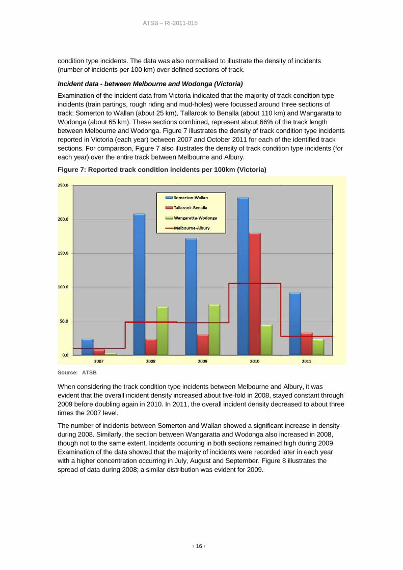
Examination of the incident data from Victoria indicated that the majority of track condition type incidents (train partings, rough riding and mud-holes) were focussed around three sections of track; Somerton to Wallan (about 25 km), Tallarook to Benalla (about 110 km) and Wangaratta to Wodonga (about 65 km). These sections combined, represent about 66% of the track length between Melbourne and Wodonga. Figure 7 illustrates the density of track condition type incidents reported in Victoria (each year) between 2007 and October 2011 for each of the identified track sections. For comparison, Figure 7 also illustrates the density of track condition type incidents (for each year) over the entire track between Melbourne and Albury.
Figure 7: Reported track condition incidents per 100km (Victoria)
Source: ATSB
When considering the track condition type incidents between Melbourne and Albury, it was evident that the overall incident density increased about five-fold in 2008, stayed constant through 2009 before doubling again in 2010. In 2011, the overall incident density decreased to about three times the 2007 level.
The number of incidents between Somerton and Wallan showed a significant increase in density during 2008. Similarly, the section between Wangaratta and Wodonga also increased in 2008, though not to the same extent. Incidents occurring in both sections remained high during 2009. Examination of the data showed that the majority of incidents were recorded later in each year with a higher concentration occurring in July, August and September. Figure 8 illustrates the spread of data during 2008; a similar distribution was evident for 2009.

› 17 ‹
ATSB – RI-2011-015
Figure 8: Incident data (per 100 km) for 2008 (Victoria)
Source: ATSB
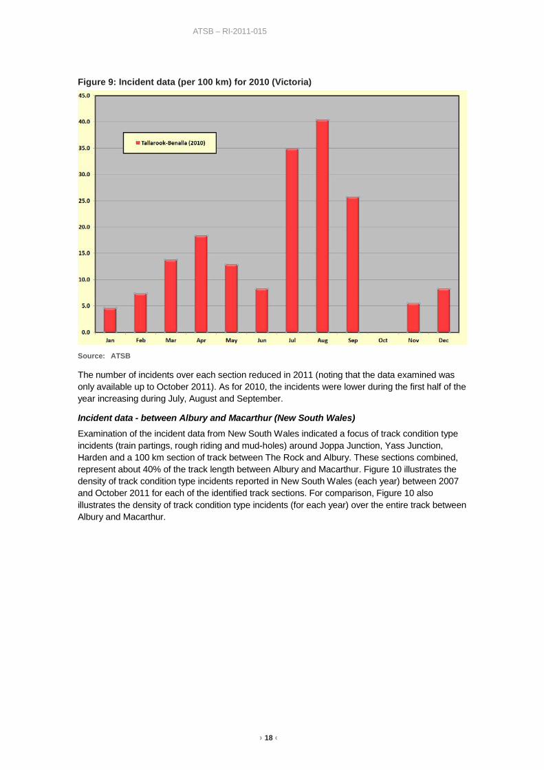
The number of incidents between Tallarook and Benalla showed a slight increase in density during 2008 (remaining constant during 2009), but was relatively low when compared to the increases over the other sections and when compared to the incident density over the entire track. Figure 7 also shows that in 2010, the density of incidents between Tallarook and Benalla increased significantly.
Similar to the other sections of track during previous years, examination of the data showed a high concentration of incidents during July, August and September. In 2010, a large proportion of incidents also occurred during the first half of the year. Figure 9 illustrates the spread of data during 2010 for the section of track between Tallarook and Benalla23.
23 In the second half of 2009, the original broad gauge line (west line) was gauge converted and opened for standard
gauge traffic. It is possible that the introduction of incident data for the west line may have contributed (in part) to the data distribution after this time,
› 18 ‹
ATSB – RI-2011-015
Figure 9: Incident data (per 100 km) for 2010 (Victoria)
Source: ATSB
The number of incidents over each section reduced in 2011 (noting that the data examined was only available up to October 2011). As for 2010, the incidents were lower during the first half of the year increasing during July, August and September.
Incident data - between Albury and Macarthur (New South Wales)
Examination of the incident data from New South Wales indicated a focus of track condition type incidents (train partings, rough riding and mud-holes) around Joppa Junction, Yass Junction, Harden and a 100 km section of track between The Rock and Albury. These sections combined, represent about 40% of the track length between Albury and Macarthur. Figure 10 illustrates the density of track condition type incidents reported in New South Wales (each year) between 2007 and October 2011 for each of the identified track sections. For comparison, Figure 10 also illustrates the density of track condition type incidents (for each year) over the entire track between Albury and Macarthur.

› 19 ‹
ATSB – RI-2011-015
Figure 10: Reported track condition incidents per 100 km (New South Wales)
Source: ATSB
When considering the track condition type incidents between Macarthur and Albury, the increase in overall incident density was less than Victoria. The overall incident density between Macarthur and Albury increased slightly in 2008 and again in 2009 before almost doubling in 2010 and dropping in 2011. The overall incident density in 2010 was only about three times that of 2007, whereas in Victoria the 2010 figure was about 10 times that of 2007.
The number of incidents that occurred in the track sections identified above increased slightly in 2008 and then significantly increased in 2009. Examination of the data showed that the majority of incidents were recorded later in each year with a higher concentration occurring in August, September and October. Figure 11 illustrates the spread of data during 2009.

› 20 ‹
ATSB – RI-2011-015
Figure 11: Incident data (per 100 km) for 2009 (New South Wales)
Source: ATSB
In 2010 and 2011 (not illustrated), the concentration of incidents (for each track section) was more evenly distributed over the year, though there was still a slightly higher concentration in August and September 2010.
Speed restrictions As described in the section titled Inspection and Maintenance, the condition of the track is managed through a process of inspection and maintenance. Where inspections identify potential track geometry defects, action is taken to rectify the problem or strategies are applied to ensure safe passage of rail traffic until defects are repaired. The primary strategy for managing the safe passage of rail traffic over deteriorated track, and through worksites, is the application of speed restrictions. If multiple locations exist where track deterioration and subsequent repair works are required, the application of speed restrictions can significantly increase train running times along the rail corridor. Consequently, lost time due to speed restrictions (train running) can be used as a trend indicator for the extent of deteriorated track and maintenance activities.
Between Melbourne and Wodonga (Victoria), lost time was relatively low during 2007, but increased from late 2007 through 2008 and remained relatively high in 2009 before increasing further in 2010. In general, higher levels of lost time were experienced during the winter months. This pattern appeared to be consistent with the pattern of track condition type incidents between Melbourne and Wodonga (see section titled Incident data).
In New South Wales, lost time due to temporary speed restrictions between Albury and Macarthur appeared to be relatively constant through 2007, 2008 and 2009, with only a couple of higher months evident in early and late 2008. It was not until 2010 that any significant increase was observed. Again, the pattern appeared to be consistent with the pattern of track condition type incidents between Albury and Macarthur (see section titled Incident data).
For both States, data from 2007 (before installation of concrete sleepers) was taken as a base representation of track condition (in terms of lost time due to temporary speed restrictions). In examining the data, there was about twice as much lost time running in New South Wales
› 21 ‹
ATSB – RI-2011-015
compared to Victoria (2007). This would appear reasonable since the track length in New South Wales was almost twice the length of that in Victoria. While the time lost in both States increased through 2008, 2009 and 2010, the increase in Victoria was more significant. It clearly exceeded the levels experienced in New South Wales. This reflects the track condition incident data (see section titled Incident data) which showed that incident density in 2010 was about three times that observed during 2007 in New South Wales and about 10 times that in Victoria.
Track quality index (TQI) The ARTC uses a ‘Track quality index’ (TQI) to provide an indication of track condition for specific sections of track. A TQI is derived from statistical analysis (three-standard-deviation24) of track geometry car data for vertical alignment, horizontal alignment, twist and gauge over 100 m sections of track. The summation of the four calculated indices provides a combined TQI for each 100 m section of track. Values are then averaged to give a TQI for longer sections of track or a rail corridor25.
The intent of the TQI is not to provide a quantifiable pass/fail indication of track condition, nor is it used to identify specific track defects. TQI provides an overview of track quality and longer term trend analysis for strategic programming of track improvement works on the rail corridor. The ARTC typically reports on the percentage of track for each corridor that exceeds a TQI value of 25, considered (based on historical experience) as an optimal target maintenance level for concrete sleepered track. Specific track irregularities are identified through track inspection and track geometry car exception reports.
The ATSB examined TQI data derived from track geometry car measurements of the Melbourne to Sydney rail line. The intent was to compare any changes to the TQI data (track condition) with respect to maintenance works and environmental impact such as rain events.
Track quality - between Melbourne and Wodonga (Victoria)
Figure 12 illustrates the average TQI figures for the standard gauge track26 between Melbourne and Wodonga. Examination of the data indicated that before 2007, the combined average TQI was generally just below 30. In 2007, the combined average TQI increased to 31.8 before decreasing to 21.8 in September 2011. This would suggest an overall improvement in track quality since 2008, but this is inconsistent with the track condition incident data which increased between 2008 and 2010 (see section titled Incident data).
When examining the individual indices, the average TQI for track gauge decreased from about 8.3 (before 2007) to about 2.5 (by September 2011) and is probably a reflection of the better gauge holding afforded by the concrete sleepers. The average TQI for horizontal alignment also showed improvement over the same period. These two indices were the primary reason for the improvement to the combined average TQI. However, the average TQI for vertical alignment and twist showed no signs of improvement and at times showed deterioration in condition. This to a train driver would be perceived as poor ride quality much more so than deterioration in gauge or horizontal alignment, especially considering the stiffer, harder riding properties of concrete sleepered track.
24 Standard deviation is a statistical calculation that indicates how tightly a selection of data points is clustered around the
average for that data. 25 The TQI has no units. A high TQI figure implies poor track condition. 26 The broad gauge (western) track is not included in this illustration.

› 22 ‹
ATSB – RI-2011-015
Figure 12: Average TQI – Melbourne to Wodonga (Victoria)
Source: ATSB
Further examination of the track condition incident data (see section titled Incident data) showed two sections of track where a significant increase in incident density occurred. The track between Somerton and Wallan exhibited a significant increase during 2008, while between Tallarook and Benalla a significant increase occurred in 2010. These sections were also examined with respect to TQI.
Figure 13 illustrates the average TQI figures for the standard gauge track between Somerton and Wallan. Examination of the individual indices showed a significant improvement for track gauge between June 2007 and October 2007, which coincides with the installation of concrete sleepers. There was also a corresponding (though not so significant) improvement to horizontal alignment, vertical alignment and twist during the same period. However, by June 2008, the figures for vertical alignment and twist had increased again and were at their highest levels since 2003. While the overall average TQI may have improved between Somerton and Wallan since June 2007 (consistently below the ARTC’s target of 25), the track condition elements of vertical alignment and twist deteriorated.

› 23 ‹
ATSB – RI-2011-015
Figure 13: Average TQI – Somerton to Wallan (Victoria)
Source: ATSB
Figure 14 illustrates the average TQI figures for the track between Tallarook and Benalla. Examination of the individual indices showed a significant improvement for track gauge and horizontal alignment between June 2009 and October 2009, which coincides with the installation of concrete sleepers. However, the figures for vertical alignment and twist had appeared to have gradually increased since 2003 and showed no obvious improvements due to the installation of concrete sleepers. While the overall average TQI may have improved between Tallarook and Benalla since June 2009 (consistently below the ARTC’s target of 25), the track condition elements of vertical alignment and twist deteriorated.

› 24 ‹
ATSB – RI-2011-015
Figure 14: Average TQI – Tallarook to Benalla (Victoria)
Source: ATSB
Track quality - between Albury and Macarthur (New South Wales)
Figure 15 illustrates the average TQI figures (combined up and down) tracks between Albury and Macarthur (New South Wales). Examination of the data indicated that before 2007, the combined average TQI was generally about 30. After 2007, the combined average TQI gradually decreased to about 25 by January 2009 increasing slightly to 26.2 in July 2011. While the decrease in TQI was not as significant as that in Victoria, the reduction still implied an overall improvement in track quality since 2008. However, similar to Victoria, this conclusion does not appear consistent with the track condition incident data (see section titled Incident data) as the density of track condition type incidents increased between 2008 and 2010.
When examining the individual indices, it is evident that the average TQI for track gauge decreased from about 6.0 (before 2007) to about 4.4 (by July 2011). The average TQI for horizontal alignment also showed slight improvement over the same period. Unlike Victoria, the average TQI for vertical alignment showed gradual improvement from 2004 until late 2008 before increasing slightly by July 2011. The average TQI for twist remained relatively constant.

› 25 ‹
ATSB – RI-2011-015
Figure 15: Average TQI – Albury to Macarthur (New South Wales)
Source: ATSB
An example from the track condition incident data (see section titled Incident data) showed significant increases in incident density near Joppa Junction and Yass Junction. Figure 16 illustrates the average TQI figures for the up track near Joppa Junction. Examination of the data showed an improvement against all indices between July 2008 and November 2008, which coincides with the installation of concrete sleepers. The average TQI figures for track gauge and horizontal alignment then remained relatively constant until June 2011. However, the figures for vertical alignment and twist gradually increased to pre-2008 levels over the same period. While an initial improvement to overall average TQI may have occurred near Joppa Junction after concrete sleepers were installed, vertical alignment and twist deteriorated.

› 26 ‹
ATSB – RI-2011-015
Figure 16: Average TQI – Up track near Joppa Junction (New South Wales)
Source: ATSB
Figure 17 illustrates the average TQI figures for the up track near Yass Junction. Examination of the data showed similar results to that of the track near Joppa Junction. Again, an initial improvement to overall average TQI occurred between July 2008 and November 2008 (coinciding with the installation of concrete sleepers), but the track condition elements of vertical alignment and twist indicate deterioration after that date. Examination of the data for the down track showed similar results which again coincide with the installation of concrete sleepers.
Figure 17: Average TQI – Up track near Yass Junction (New South Wales)
Source: ATSB
› 27 ‹
ATSB – RI-2011-015
Summary of track condition An examination of track condition type incidents (train partings, rough riding and mud-holes) occurring between Melbourne and Wodonga showed that, compared to 2007 figures, the density of incidents increased about five-fold in 2008, stayed constant through 2009 before doubling again in 2010. Between Macarthur and Albury, the change in density of incidents was not as significant as that in Victoria, but still showed a slight increase in 2008 and 2009 before almost doubling in 2010. The 2010 incident density in New South Wales was about three times that of 2007, whereas in Victoria the 2010 figure was about 10 times that of 2007.
In each State, there were sections of track that appeared to have a higher concentration of track condition type incidents. While each track section experienced a noticeable and significant increase in the number of track condition type incidents at some point in time after 2007, the timing of the increase varied between track sections. That is, some locations experienced an increase in 2008, while other areas experienced an increase in 2009 or 2010. In general, all track sections exhibited a higher concentration of incidents during July, August and September, though in 2010 a large proportion of incidents also occurred during the first half of the year.
An increased number of speed restrictions due to deteriorated track condition and subsequent maintenance activities resulted in extended train running times along the rail corridor. Both States experienced increased lost time running due to track deterioration and increased maintenance activities through 2008, 2009 and 2010. The pattern of increased lost time running due to temporary speed restrictions was similar to the pattern of track condition type incidents in that changes in Victoria were more significant to that experienced in New South Wales.
An examination of TQI data indicated that the combined average TQI for the Melbourne to Sydney track had gradually improved since 2007, implying an overall improvement in track quality. However, this conclusion was not consistent with the track condition incident data (see section titled Incident data) which generally showed an increase in track condition type incidents between 2008 and 2010.
When examining the individual indices of TQI, it was evident that the average TQI for track gauge and horizontal alignment improved after concrete sleepers were installed. While initial improvement may have been evident to vertical alignment and twist TQI generally returned to pre-concrete-installation levels during the following months. In some cases, a continuing trend of progressive deterioration appeared to exist in the average TQI figures for vertical alignment and twist.
It was evident that the installation of concrete sleepers between Melbourne and Sydney provided sustainable improvements to track gauge and horizontal alignment. However, there was no evidence to suggest any improvement for vertical alignment and twist. Conversely, it could not be concluded from TQI data that the installation of concrete sleepers had directly influenced a deterioration of vertical alignment or twist.
The changes to TQI data were consistent with the recognised advantages of concrete sleepered track, that is the ability to resist horizontal misalignment (due to heavier mass) and more effectively holding track gauge, both elements which significantly reduced the risk of train derailment. The TQI data did not show the same improvement for vertical alignment and twist. From a train driver’s perspective, any reduced risk of derailment due to improved track gauge and horizontal alignment would be less apparent than poor ride quality due to deterioration of vertical alignment and twist, especially considering the stiffer, harder riding properties of concrete sleepered track.

› 28 ‹
ATSB – RI-2011-015
Track condition and safety This section examines the measures that have been put in place to maintain the safety of rail operations where track quality is below acceptable operational standards.
As discussed in the section titled Inspection and Maintenance, inspection and maintenance is the process of ensuring infrastructure is maintained at a level that is safe and reliable for rail operations. The process is based on a regime of inspection to detect defects, assessment to determine the required response and corrective action to repair the defect or manage the defect until a long term solution can be applied.
The standards for ARTC track infrastructure management are documented in Section 5, Track Geometry of the ARTC Engineering (Track & Civil) Code of Practice. The document specifies the requirements, specifications and procedures related to track geometry that require management to ensure the track infrastructure performs as intended while remaining safe and reliable.
The code of practice adopted by the ARTC is based on a set of standards and procedures that have been developed over many years by the rail industry as a whole. Where track has been designed and constructed in accordance with the code of practice, it is generally accepted that the documented inspection and maintenance regime is adequate.
In the context of this investigation, reports of rough riding and mud-holes were the track conditions of greatest concern to train drivers. Examination of track condition between Melbourne and Sydney suggested that deterioration of vertical alignment and twist were the elements that most likely contributed to these reports.
The inspection and maintenance process utilises a combination of driver reports, scheduled inspections and unscheduled inspections to identify and manage track geometry defects. Where defects are identified as exceeding defined limits, action should be taken to ensure the safe passage of rail traffic. The principal action taken is the application of a ‘Temporary Speed Restriction’ (TSR) over the affected section of track until the defect is repaired.
Temporary speed restrictions (TSR) The process of applying speed restrictions is an internationally accepted method for maintaining the safety of rail operations over deteriorated track. Since commencing the concrete re-sleepering project between Melbourne and Sydney, the combination of track works, reports of rough riding and the development of mud-holes required the application of speed restrictions in some locations to maintain track safety. While TSRs aim to ensure safe rail operations, the consequence can be an increase to trip duration. As mentioned in the section titled ‘Track condition’, lost (train running) time due to speed restrictions increased throughout the re-sleepering project (2008 onwards), especially in 2010, and was more significant in Victoria than in New South Wales.
In some cases, multiple track defects in relatively rapid succession required the application of multiple speed restrictions. The ATSB conducted a number of interviews with train drivers who regularly travel the line between Melbourne and Sydney. The interviews identified the potential for confusion where multiple restrictions resulted in a high density of TSR signage. Considering the critical role of a TSR in managing safe rail operations, the process for applying TSRs was examined and reported in detail in an Interim Factual Report27. The discussion regarding temporary speed restriction (as published in the ATSB Interim Report) is shown in Appendix A – Temporary speed restrictions. Based on the available evidence, the ATSB found that:
27 ATSB Interim Factual Report – Investigation of the safety of rail operations on the interstate rail line between Melbourne
and Sydney – published in February 2012.

› 29 ‹
ATSB – RI-2011-015
• The rules and procedures for applying TSRs were different between New South Wales and Victoria. In general, training, experience and driver professionalism has reduced the safety risk associated with unique state based rules and procedures. However, a risk remained that operating under multiple rules and procedures has the potential to create driver confusion and as such may impact on rail safety.
• The process of applying TSRs is critical to maintaining safety of rail operations over deteriorated track. However, in some cases, TSR signage had not been installed as per the rules and procedures. In some cases the incorrect application of the TSR meant that a TSR no longer applied over a section of track where a speed restriction was intended to remain. Based on information provided to the ATSB, it appeared as though maintenance personnel had applied a second (short section) TSR without knowledge or consideration of a first (long section) TSR.
• The rules for applying TSRs on the ARTC network in Victoria (TA20) did not provide any guidance where multiple TSRs may be required within 2500 m of each other, nor where a TSR may be required within the boundaries of another TSR. Without any guidance to the contrary, it was possible that signage may be applied without consideration of adjacent or nearby TSRs, with the potential that a restriction may be released where a TSR was intended to remain.
• The use of additional (or intermediate) TSR ‘Warning’ signs is not specifically covered under the rules in New South Wales, but a warning sign is mandatory prior to all ‘Caution’ signs under the rules in Victoria. In each case, scenarios exist that may increase the risk to safe rail operations: - Where a second restriction is required some distance (greater than 2500 m) within the
boundaries of a longer speed restricted section of track, a warning sign would be advantageous to provide drivers with warning of an impending additional TSR within the section, consistent with the warning provided at other restrictions. This is not specifically covered under the existing rules in New South Wales.
- Where multiple TSRs are relatively close to each other, a warning sign before each TSR can result in warning signs interspersed within the signage of an unrelated TSR. This may contribute to ‘sign clutter’ and an increased risk of driver confusion. This TSR sign configuration is mandatory under the rules in Victoria.
• Records showed that multiple TSRs were often applied within a relatively short distance of each other, meaning trains had limited opportunity to increase speed before slowing in preparation for the next restriction. While frequent TSRs may be adequate from a track condition point of view, a single restriction combining the requirements of multiple track defects may be more appropriate from an operational perspective. The opportunity exists for the ARTC to consider the practical consequences on rail operations when applying frequent TSRs.
The ARTC advised of a number of actions taken to improve safety over the rail network, including actions relating to the application of TSRs. These actions are detailed in the section titles ‘Actions taken to improve safety’.
Short term remediation work In many cases, a visual on-site inspection (referred to in the code of practice as a ‘general inspection’) is initiated when potential geometry defects are identified or rough track is reported. However, geometry defects due to mud-holes, fouled ballast or soft formation may not always be apparent because the relatively light weight road-rail vehicles used by track patrols may not detect any significant deflection while travelling along the track, even though fouled ballast may be visible.
As discussed in the section titled Track condition, it is evident that sections of track between Melbourne and Sydney experienced increased levels of degradation in vertical track alignment and twist, or a perceived degradation due to poor ride quality, during the years after 2007. While the ARTC continued to inspect and assess the track in accordance with the existing code of
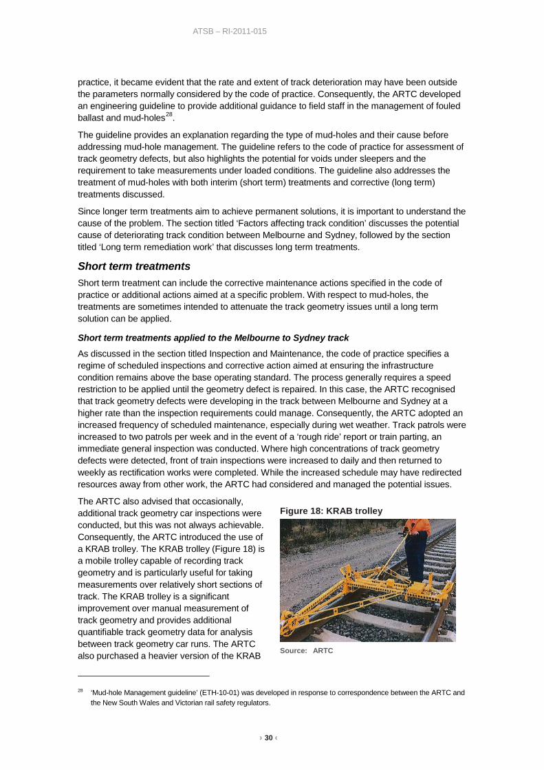
› 30 ‹
ATSB – RI-2011-015
practice, it became evident that the rate and extent of track deterioration may have been outside the parameters normally considered by the code of practice. Consequently, the ARTC developed an engineering guideline to provide additional guidance to field staff in the management of fouled ballast and mud-holes28.
The guideline provides an explanation regarding the type of mud-holes and their cause before addressing mud-hole management. The guideline refers to the code of practice for assessment of track geometry defects, but also highlights the potential for voids under sleepers and the requirement to take measurements under loaded conditions. The guideline also addresses the treatment of mud-holes with both interim (short term) treatments and corrective (long term) treatments discussed.
Since longer term treatments aim to achieve permanent solutions, it is important to understand the cause of the problem. The section titled ‘Factors affecting track condition’ discusses the potential cause of deteriorating track condition between Melbourne and Sydney, followed by the section titled ‘Long term remediation work’ that discusses long term treatments.
Short term treatments Short term treatment can include the corrective maintenance actions specified in the code of practice or additional actions aimed at a specific problem. With respect to mud-holes, the treatments are sometimes intended to attenuate the track geometry issues until a long term solution can be applied.
Short term treatments applied to the Melbourne to Sydney track
As discussed in the section titled Inspection and Maintenance, the code of practice specifies a regime of scheduled inspections and corrective action aimed at ensuring the infrastructure condition remains above the base operating standard. The process generally requires a speed restriction to be applied until the geometry defect is repaired. In this case, the ARTC recognised that track geometry defects were developing in the track between Melbourne and Sydney at a higher rate than the inspection requirements could manage. Consequently, the ARTC adopted an increased frequency of scheduled maintenance, especially during wet weather. Track patrols were increased to two patrols per week and in the event of a ‘rough ride’ report or train parting, an immediate general inspection was conducted. Where high concentrations of track geometry defects were detected, front of train inspections were increased to daily and then returned to weekly as rectification works were completed. While the increased schedule may have redirected resources away from other work, the ARTC had considered and managed the potential issues.
The ARTC also advised that occasionally, additional track geometry car inspections were conducted, but this was not always achievable. Consequently, the ARTC introduced the use of a KRAB trolley. The KRAB trolley (Figure 18) is a mobile trolley capable of recording track geometry and is particularly useful for taking measurements over relatively short sections of track. The KRAB trolley is a significant improvement over manual measurement of track geometry and provides additional quantifiable track geometry data for analysis between track geometry car runs. The ARTC also purchased a heavier version of the KRAB
28 ‘Mud-hole Management guideline’ (ETH-10-01) was developed in response to correspondence between the ARTC and
the New South Wales and Victorian rail safety regulators.
Figure 18: KRAB trolley
Source: ARTC

› 31 ‹
ATSB – RI-2011-015
trolley, designed to be towed behind a road-rail vehicle, which assists with measurement over longer track distances. The ARTC also experimented with the use of ground penetrating radar29 to determine the location and extent of ballast pockets.
Since one of the main contributors associated with deteriorating track structure due to mud-holes and soft formation is water, much of the remediation work involved the removal and management of water on and around the track structure. Short term treatments implemented by the ARTC generally involved draining the water away from the problem areas. For short sections of track, narrow drains were formed through the ballast and away from the sleepers. For longer sections, more extensive removal of ballast from the sleeper ends was adopted, with consideration of the lateral stability of the track structure. Once the track was drained of water, the track was lifted and additional ballast forced under the sleepers (tamping) to obtain the correct track geometry.
Rail safety regulation At the time the investigation commenced, each State had a rail safety regulator (the Independent Transport Safety Regulator (ITSR) in New South Wales and Transport Safety Victoria (TSV) in Victoria responsible for administering the requirements of each state’s rail safety legislation30. The rail safety legislation specified the requirements for organisations responsible for rolling stock and infrastructure management with each regulators administering these requirements and facilitating the safe operation of railway operations through processes including accreditation, safety audits, compliance inspections and investigations.
The condition and safety of the Melbourne to Sydney line was the subject of close attention by both ITSR and TSV.
From about mid-2008 ITSR became increasingly concerned about mud-holes on the NSW section of the line and while it acknowledged that speed restrictions had been imposed by ARTC to ensure safe operations along the corridor, ITSR also recognised that a marked increase in transit times could lead to other safety concerns such as driver fatigue. During this time TSV were also becoming increasingly concerned about the safety of rail operations on the Victorian side of the line and together with ITSR were actively monitoring the ARTC for compliance with applicable engineering standards and also verifying that the standards themselves provided the necessary margin of safety and, where safety was considered to be at risk, issued appropriate improvement notices.
Following ITSR’s and TSV’s regulatory activity, the ARTC developed an engineering guideline (ETH-10-01 Mud-hole Management guideline). The guideline provided an explanation regarding the type, cause and treatment of mud-holes to ensure safe rail operations.
In 2010, TSV commissioned an independent consultant to conduct on track vehicle behaviour testing between Melbourne and Albury. The testing was performed in response to driver concerns regarding rough sections of track and involved mounting electronic measuring equipment in the driving cabins of both on XPT power car and a freight locomotive. The equipment measured the triaxial accelerations at both the vehicle floor and driver’s seat as the vehicle travelled between Melbourne and Albury.
The testing identified that both vehicles exceeded the acceleration limits specified by European standard DS/EN 14363 ‘Railway applications - Testing for the acceptance of running characteristics of railway vehicles - testing of running behaviour and stationary tests’, which was
29 Ground penetrating radar uses electromagnetic radiation in the microwave band (UHF/VHF frequencies) of the radio
spectrum, and detects the reflected signals from subsurface structures. 30 On 20 January 2013, the Office of the National Rail Safety Regulator (ONRSR) became the rail safety regulator for rail
activities in New South Wales, South Australia, Tasmania and the Northern Territory with an expectation that Western Australia, Victoria, Queensland and the Australian Capital Territory would also be regulated by the ONRSR within about 12 months.
› 32 ‹
ATSB – RI-2011-015
considered as having criteria suitable for assessing derailment risk. The tests also revealed that the ride quality in the cabin of the XPT vehicle was generally worse than that of the freight locomotive.
The ARTC expressed a difference of opinion regarding the standard applied and conducted similar tests and referencing a UK Railway Group Standard GM/RT2141 ‘Resistance of Railway Vehicles to Derailment and Roll-Over’. The ARTC tests concluded that the freight locomotive was not likely to derail during operations under the prevailing track and speed conditions between Melbourne and Albury.
While the ARTC disputed the use of the European standard they still imposed additional speed restrictions to locations between Melbourne and Albury. As a consequence of significant speed restrictions across the network, RailCorp suspended the XPT service due to extended travel times. While the decision to suspend services was more to do with operational efficiency than safety, it did focus additional attention on the ARTC’s management of the mud-hole issue and any potential safety issues.
Both ITSR and TSV have continued to monitor, audit and inspect the activities of the ARTC with respect to safety on the rail network. While issues associated with mud-holes and safe rail operations have been of specific interest, the regulators have also considered other issues such as the safety of track workers. In each case initiatives have been taken to identify vulnerabilities within the rules and procedures, with actions taken and monitored to ensure systems are safe so far as is reasonably practicable.
With the introduction of the Office of the National Rail Safety Regulator, safety of the rail network will continue to be managed through the regulatory process, though with an increasingly more national perspective.
Summary of track condition and safety The ARTC has adopted a combination of both short and long term treatments to remediate the track problems that have developed between Melbourne and Sydney. The short term treatments were intended to manage the problems until long term solutions could be applied.
The ARTC recognised that track geometry defects were developing at a higher rate than the inspection requirements (documented in the code of practice) could manage. Consequently, the ARTC adopted an increased inspection and maintenance frequency, especially during wet weather. Where geometry defects were identified, actions were applied as specified in the code of practice. These included the application of speed limits to ensure the safe passage of train operations plus spot maintenance works to manage the defects until corrective actions could be applied.
Safety of the Melbourne to Sydney line is being maintained largely through the application of temporary speed restrictions, although increased maintenance activities and speed restrictions have resulted in extended train running times along the corridor. Lost time running increased through 2008, 2009 and 2010 and was more significant in Victoria than in New South Wales.
While the application of temporary speed restrictions may in general control the safety risk, the system still relies on prompt identification of track condition hazards before the control measures can be implemented. If the track is performing in a constantly poor and degraded condition, there is an increased risk that defects compromising safety are not immediately identified. In this case, the ARTC have increased the inspection regime to mitigate this risk. However, if the system was performing well, it is likely to be inherently safer since it would place fewer burdens on the defect identification process.
A number of issues were identified in the ATSB Interim Report, where the opportunity existed to further improve the safety of operations across the ARTC rail network. These were associated with the process and application of temporary speed restrictions. The ARTC advised that a

› 33 ‹
ATSB – RI-2011-015
combination of improved TSR management and the implementation of a Ballast Rehabilitation Plan had improved track condition and significantly reduced the number of TSRs on the Melbourne to Sydney line. The works conducted over the 15 months since late December 2011 had improved lost transit times by about 50%.

› 34 ‹
ATSB – RI-2011-015
Factors affecting track condition This section examines the factors that may influence track condition and which of these factors may have been affected the condition of track between Melbourne and Sydney. The section provides a context to the following discussion on the actions taken by the Australian Rail Track Corporation (ARTC) to remediate the track and address the safety of rail operations.
While track infrastructure will progressively deteriorate over time and use, the rate of deterioration may be affected by many factors including the initial design, level of maintenance and type/volume of operations. Based on an examination of incident and TQI data (Melbourne to Sydney) there was evidence of degradation in vertical track alignment and twist over sections of the track following concrete re-sleepering. This would have contributed to the poor quality ride reported by drivers.
The ATSB therefore examined factors that may have contributed to the deterioration of vertical alignment and twist, and would have result in increased reports of rough riding and the associated/likely development of mud-holes.
Load distribution31 The foundation or base component of the track structure is the formation. The formation usually consists of the sub-grade (earth fill on top of the natural earth) and a capping layer (compacted material that provides a sealing layer to the sub-grade), though a capping layer may not always exist in older track. There are limits to what the formation can support before the risk of shear failure or settlement becomes unacceptable. From a design perspective, the limits are referred to as the allowable bearing pressure or the design limit of the sub-grade pressure (expressed in kPa) and are dependent on the type and quality of the sub-grade material.
As mentioned previously (see section titled Track structure - description), a function of the track (rail, sleepers, fasteners and ballast) is to transfer the train load to the formation at a pressure tolerable to the sub-grade. The distribution of load occurs through the principle of stress reduction by progressively distributing the load over an ever increasing area.
The first loaded element of the track structure is the rail which supports the wheel load through the wheel/rail contact area (about 1 cm2 per wheel). The rail is effectively a beam that then distributes the load through the rail foot area (about 240 cm2 per rail)32, over multiple supports, in this case the sleepers. The next element is the sleeper which, similar to the rail, is a beam that supports the two rails and distributes the load to the ballast (the effective sleeper support area is about 2500 cm2 under each rail).
The ballast then distributes the load to the sub-grade or formation. While there are a number of published methods for analysing how the sleeper loading is transferred to the formation, a simplified approach is to assume a uniform spread of load relative to the depth of ballast below the sleeper. For example, one solution33 states that ballast quality has an influence on the distribution of vertical pressure and suggests a friction angle upper limit of 40° for coarse, rough, dry ballast (good quality) and a lower limit of 30° for fine, smooth, moist ballast (poor quality). The solution also states that it is desirable to retain some level of vertical pressure across the entire formation. If the friction angle is projected from the corner of each sleeper, the minimum ballast depth is at
31 Most of the concepts presented in this section are documented in the Railways of Australia (ROA) publication
‘A Review of Track Design Procedures, Volume 2, Sleepers and Ballast’ 1991. 32 Assuming 60 kg/m rail supported on concrete sleepers to ARTC standard ETD-02-03, ‘Concrete Sleepers (Heavy Duty)
– Design’. 33 Schramm (1961) as cited in the ROA publication ‘A Review of Track Design Procedures’

› 35 ‹
ATSB – RI-2011-015
the point where the projections intercept (Figure 19). Consequently, the theoretical minimum ballast depth is a function of the friction angle, sleeper width and sleeper spacing.
Figure 19: Load distribution to formation
Source: ATSB
The final element of the track structure is the formation itself. As mentioned above, there are limits to what the formation can support before the risk of shear failure or settlement becomes unacceptable. The limits are dependent on the formation material. Poor or unsuitable sub-grade materials may result in an overstressed formation that cannot adequately support the distributed load. Conversely, a very good sub-grade may create a formation that would be capable of supporting the more concentrated load resulting from a lower than desirable ballast depth.
In general, sub-grade material should have good bearing strength and stability. Materials that are not ideal include topsoil, highly organic soils, free draining materials susceptible to scouring, and moisture reactive clay soils.
Load distribution – Melbourne to Sydney track
The general design specification for the track between Melbourne and Sydney called for 60 kg/m rail34 fixed to concrete sleepers with 667 mm spacing (1500 sleepers per kilometre) and a minimum 250 mm ballast depth below each sleeper. Adopting a simplified method for assessing load distribution on the formation, this general design specification appears appropriate (assuming good quality ballast and therefore a friction angle of 40°), though without any tolerance for variation. That is, if sleeper spacing was slightly more, ballast depth slightly less or ballast quality slightly poor, then load distribution would probably be undesirable.
The decision to install new concrete sleepers with minimal new ballast (see section titled Economics and safety) meant that the existing and generally poor quality ballast was to be retained (at least until future maintenance programs replaced or cleaned the existing ballast). In addition, in many areas the new concrete sleepers were inserted without any change to rail
34 While 47 kg rail is used in some locations in Victoria, much has been replaced by 60kg rail. In NSW, the rail is
predominantly 53 kg but with extensive areas of 60 kg rail.
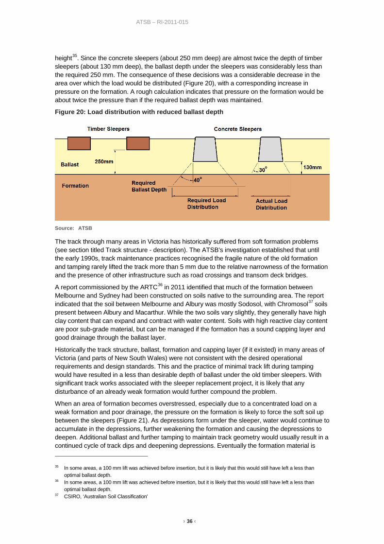
› 36 ‹
ATSB – RI-2011-015
height35. Since the concrete sleepers (about 250 mm deep) are almost twice the depth of timber sleepers (about 130 mm deep), the ballast depth under the sleepers was considerably less than the required 250 mm. The consequence of these decisions was a considerable decrease in the area over which the load would be distributed (Figure 20), with a corresponding increase in pressure on the formation. A rough calculation indicates that pressure on the formation would be about twice the pressure than if the required ballast depth was maintained.
Figure 20: Load distribution with reduced ballast depth
Source: ATSB
The track through many areas in Victoria has historically suffered from soft formation problems (see section titled Track structure - description). The ATSB’s investigation established that until the early 1990s, track maintenance practices recognised the fragile nature of the old formation and tamping rarely lifted the track more than 5 mm due to the relative narrowness of the formation and the presence of other infrastructure such as road crossings and transom deck bridges.
A report commissioned by the ARTC36 in 2011 identified that much of the formation between Melbourne and Sydney had been constructed on soils native to the surrounding area. The report indicated that the soil between Melbourne and Albury was mostly Sodosol, with Chromosol37 soils present between Albury and Macarthur. While the two soils vary slightly, they generally have high clay content that can expand and contract with water content. Soils with high reactive clay content are poor sub-grade material, but can be managed if the formation has a sound capping layer and good drainage through the ballast layer.
Historically the track structure, ballast, formation and capping layer (if it existed) in many areas of Victoria (and parts of New South Wales) were not consistent with the desired operational requirements and design standards. This and the practice of minimal track lift during tamping would have resulted in a less than desirable depth of ballast under the old timber sleepers. With significant track works associated with the sleeper replacement project, it is likely that any disturbance of an already weak formation would further compound the problem.
When an area of formation becomes overstressed, especially due to a concentrated load on a weak formation and poor drainage, the pressure on the formation is likely to force the soft soil up between the sleepers (Figure 21). As depressions form under the sleeper, water would continue to accumulate in the depressions, further weakening the formation and causing the depressions to deepen. Additional ballast and further tamping to maintain track geometry would usually result in a continued cycle of track dips and deepening depressions. Eventually the formation material is 35 In some areas, a 100 mm lift was achieved before insertion, but it is likely that this would still have left a less than
optimal ballast depth. 36 In some areas, a 100 mm lift was achieved before insertion, but it is likely that this would still have left a less than
optimal ballast depth. 37 CSIRO, ‘Australian Soil Classification’

› 37 ‹
ATSB – RI-2011-015
forced up through the ballast to the surface and likely to become recognised as a ‘mud-hole’. It is also possible that rail imperfections (localised defects) may introduce concentrated impact loading that, when transmitted through the sleepers and ballast, may also overstress the formation.
Figure 21: Depression and settling of the formation
Source: ATSB
Method of sleeper replacement Track reconditioning can range from replacing select sleepers through to replacement of rail, sleepers, ballast, and sometimes the formation and capping layer. The level of reconditioning will depend upon the state of the track, the intended use of the track, the budget and resources available, and availability to access the track. The strategy adopted on the Melbourne to Sydney line involved replacement of the sleepers and, in some areas, replacement of the rail (though not at the same time as the sleepers).
Sleeper replacement methods can be categorised as either relay or side insertion38. Relay, also referred to as reconstruction, involves removal or spreading of the rail so that the existing sleepers can be lifted out and new sleepers installed before the rail is reinstated. For the side insertion method, the rail remains in situ with the existing sleepers removed and new ones inserted from the side.
Reconstruction of track using the relay method is a typical approach used for complete sleeper replacement and can range from manual processes using earthmoving equipment to more automated processes using purpose built track laying machines. The manual processes involve cutting and removing the rail before replacing the sleepers using earthmoving equipment or sleeper laying attachments (such as an Octopus or Super spreader) mounted to hydraulic excavators. The attachments pick up sleepers from pre-positioned stacks, spread them to the desired sleeper spacing then place them into position in lots of 4, 6 or 8. When the sleepers are in the required position, the rail is reinstated.
The automated processes for reconstruction use track laying machines to lift and spread the rails, lift out the old sleepers, place new sleepers, and reinstate the rail in a continuous process. Both the new and old sleepers are stored on rail wagons hauled by the track laying machine with a shuttle travelling along the ‘train’ to transfer sleepers to and from the machine. Track laying machines are often referred to by their proprietary model names such as the Plasser (illustrated in Figure 22), the Theurer TLMs and the Harsco Pony and Pony Express.
38 Relay or side insertion is sometimes referred to as ‘On-face’ or ‘Spot’ re-sleepering.

› 38 ‹
ATSB – RI-2011-015
Figure 22: Plasser SUZ 500 UVR Track Relaying Machine
Source: Plasser Australia Pty Ltd
Side insertion methods are typically used when replacing selected sleepers39, but can also be used for replacing all sleepers within a section of track (though usually relatively short sections). Similar to relay reconstruction, side insertion methods can range from manual processes using hand tools and/or earthmoving equipment to more automated processes using purpose built machines.
The manual processes involve unclipping the rail, dragging the old sleeper out and sliding a new sleeper in from the side, then re-clipping the rail to the new sleeper. The process can be achieved using track jacks and hand tools or purpose built attachments mounted on hydraulic excavators (often rail mounted). The attachments usually incorporate a mechanical grab to manipulate the sleepers and sometimes also include devices designed to scarify the ballast and sleeper bed to make room for the new sleepers. An example commonly used in Australia is known as a Platypus.
The more automated processes use rail mounted machines, often referred to as tie inserters or tie exchangers40, to remove and insert sleepers from under the rail. An example is illustrated in Figure 23.
All of the above methods require some form of follow up ballasting and tamping of the newly installed sleepers. The reconstruction (relay) methods offer greater productivity and minimal disturbance to the formation/ballast layers, but require significant periods of track closures to realise true productivity benefits. This is due to significant setup time for large plant (automated process) or complete removal of the track (manual process) followed by significant reinstatement works. The side insertion methods typically offer lower productivity41, but have the advantage of a lower unit cost with much shorter setup and reinstatement times. Similarly, side insertion methods have the advantage that the track, whilst disturbed, can be opened during the work cycle to permit the passage of traffic under speed restriction.
39 For example, a patterned replacement of 1 in 4 sleepers. 40 In the United States (US), the term ‘Tie’ is used to describe a sleeper. Consequently, track machines designed or
manufactures in the US refer to tie, not sleeper. 41 Higher productivity is possible by utilising additional machinery and worker resources.

› 39 ‹
ATSB – RI-2011-015
Figure 23: Fairmont Tamper RT10 Tie Exchanger
Sleeper replacement – Melbourne to Sydney track
As mentioned previously (see section titled Economics and safety), side-insertion (using the rail mounted excavators fitted with Platypus attachments) was the chosen method for replacing timber and steel sleepers with concrete sleepers on the Melbourne to Sydney line. The images below (Figure 24, Figure 25 and Figure 26) illustrate the sleeper replacement process undertaken on the Melbourne to Sydney line42. The process consists of:
• Pre-marking the new sleeper position, in this case 667 mm sleeper spacing. • Unclipping and removal of the old sleepers by pulling the sleeper out from one side of the track
using the Platypus attachment. • Scarifying a ballast trench using the Platypus attachment (Figure 24) • Using the Platypus attachment to insert the new sleeper (Figure 25) • Clip the new sleeper in the required pre-marked location (Figure 26) • Tamp the track to ensure the required track geometry. While side-insertion is a valid method of sleeper replacement, there are a number of factors that need to be considered as part of the process. The main factor is the prevention of damage to the formation while scarifying the ballast in preparation for the new sleeper. With respect to replacing timber sleepers with concrete sleepers, the difference in sleeper depth is important when considering the depth of ballast under the new sleepers. As described in the previous section (titled Load distribution), the new concrete sleepers are almost twice the depth of timber sleepers. To ensure adequate ballast under the new concrete sleepers and assuming the required 250 mm ballast depth existed under the original timber sleepers, the track would require lifting either before or after the installation. If the lift was to be conducted after installation, it is critical that minimal ballast scarifying be done during installation so as to prevent damaging the formation.
42 The photographs were taken near Heathcote Junction (Victoria) in October 2007.

› 40 ‹
ATSB – RI-2011-015
Figure 24: Scarifying the ballast with a Platypus attachment
Source: John Hearsch Consulting Pty Ltd
Figure 25: Inserting a concrete sleeper using a Platypus attachment
Source: John Hearsch Consulting Pty Ltd
The process for installing concrete sleepers on the line between Melbourne and Sydney was detailed in document SIA-PPR-GL-CON-051, titled ‘South Improvement Alliance, Process Procedure, Concrete resleepering, Side insertion method’. The procedure describes the construction methodology for the installation of concrete sleepers by side insertion using excavators with Platypus attachments.
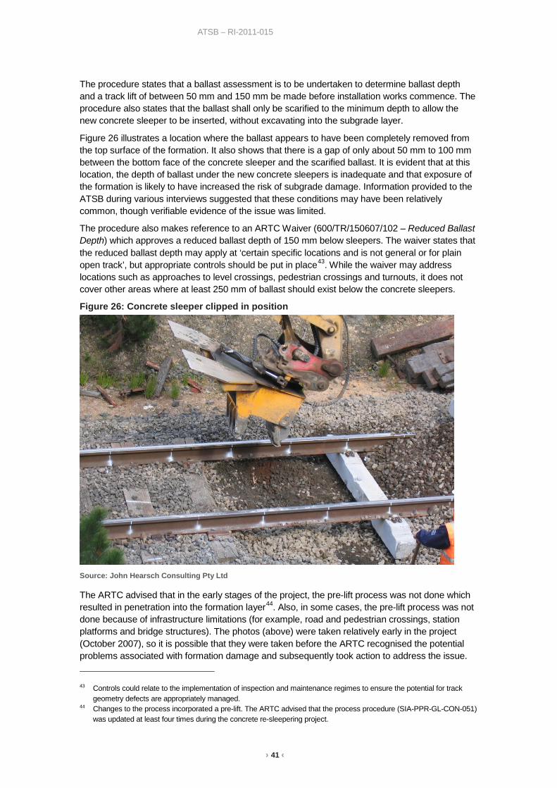
› 41 ‹
ATSB – RI-2011-015
The procedure states that a ballast assessment is to be undertaken to determine ballast depth and a track lift of between 50 mm and 150 mm be made before installation works commence. The procedure also states that the ballast shall only be scarified to the minimum depth to allow the new concrete sleeper to be inserted, without excavating into the subgrade layer.
Figure 26 illustrates a location where the ballast appears to have been completely removed from the top surface of the formation. It also shows that there is a gap of only about 50 mm to 100 mm between the bottom face of the concrete sleeper and the scarified ballast. It is evident that at this location, the depth of ballast under the new concrete sleepers is inadequate and that exposure of the formation is likely to have increased the risk of subgrade damage. Information provided to the ATSB during various interviews suggested that these conditions may have been relatively common, though verifiable evidence of the issue was limited.
The procedure also makes reference to an ARTC Waiver (600/TR/150607/102 – Reduced Ballast Depth) which approves a reduced ballast depth of 150 mm below sleepers. The waiver states that the reduced ballast depth may apply at ‘certain specific locations and is not general or for plain open track’, but appropriate controls should be put in place43. While the waiver may address locations such as approaches to level crossings, pedestrian crossings and turnouts, it does not cover other areas where at least 250 mm of ballast should exist below the concrete sleepers.
Figure 26: Concrete sleeper clipped in position
Source: John Hearsch Consulting Pty Ltd
The ARTC advised that in the early stages of the project, the pre-lift process was not done which resulted in penetration into the formation layer44. Also, in some cases, the pre-lift process was not done because of infrastructure limitations (for example, road and pedestrian crossings, station platforms and bridge structures). The photos (above) were taken relatively early in the project (October 2007), so it is possible that they were taken before the ARTC recognised the potential problems associated with formation damage and subsequently took action to address the issue. 43 Controls could relate to the implementation of inspection and maintenance regimes to ensure the potential for track
geometry defects are appropriately managed. 44 Changes to the process incorporated a pre-lift. The ARTC advised that the process procedure (SIA-PPR-GL-CON-051)
was updated at least four times during the concrete re-sleepering project.
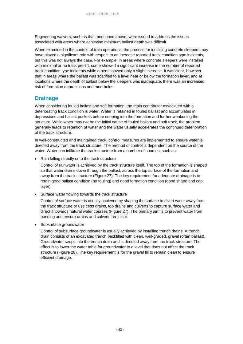
› 42 ‹
ATSB – RI-2011-015
Engineering waivers, such as that mentioned above, were issued to address the issues associated with areas where achieving minimum ballast depth was difficult.
When examined in the context of train operations, the process for installing concrete sleepers may have played a significant role with respect to an increase reported track condition type incidents, but this was not always the case. For example, in areas where concrete sleepers were installed with minimal or no track pre-lift, some showed a significant increase in the number of reported track condition type incidents while others showed only a slight increase. It was clear, however, that in areas where the ballast was scarified to a level near or below the formation layer, and at locations where the depth of ballast below the sleepers was inadequate, there was an increased risk of formation depressions and mud-holes.
Drainage When considering fouled ballast and soft formation, the main contributor associated with a deteriorating track condition is water. Water is retained in fouled ballast and accumulates in depressions and ballast pockets before seeping into the formation and further weakening the structure. While water may not be the initial cause of fouled ballast and soft track, the problem generally leads to retention of water and the water usually accelerates the continued deterioration of the track structure.
In well-constructed and maintained track, control measures are implemented to ensure water is directed away from the track structure. The method of control is dependent on the source of the water. Water can infiltrate the track structure from a number of sources, such as:
• Rain falling directly onto the track structure Control of rainwater is achieved by the track structure itself. The top of the formation is shaped so that water drains down through the ballast, across the top surface of the formation and away from the track structure (Figure 27). The key requirement for adequate drainage is to retain good ballast condition (no fouling) and good formation condition (good shape and cap layer).
• Surface water flowing towards the track structure Control of surface water is usually achieved by shaping the surface to divert water away from the track structure or use cess drains, top drains and culverts to capture surface water and direct it towards natural water courses (Figure 27). The primary aim is to prevent water from ponding and ensure drains and culverts are clear.
• Subsurface groundwater Control of subsurface groundwater is usually achieved by installing trench drains. A trench drain consists of an excavated trench backfilled with clean, well-graded, gravel (often ballast). Groundwater seeps into the trench drain and is directed away from the track structure. The effect is to lower the water table for groundwater to a level that does not affect the track structure (Figure 28). The key requirement is for the gravel fill to remain clean to ensure efficient drainage.
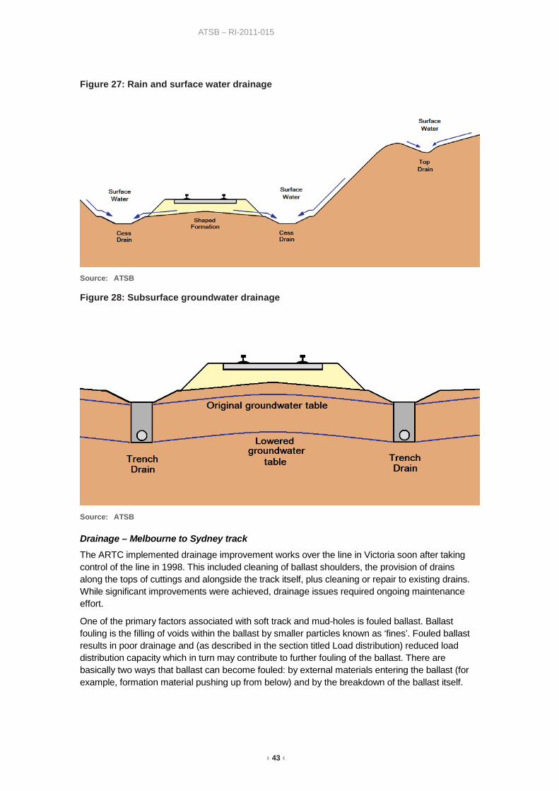
› 43 ‹
ATSB – RI-2011-015
Figure 27: Rain and surface water drainage
Source: ATSB
Figure 28: Subsurface groundwater drainage
Source: ATSB
Drainage – Melbourne to Sydney track
The ARTC implemented drainage improvement works over the line in Victoria soon after taking control of the line in 1998. This included cleaning of ballast shoulders, the provision of drains along the tops of cuttings and alongside the track itself, plus cleaning or repair to existing drains. While significant improvements were achieved, drainage issues required ongoing maintenance effort.
One of the primary factors associated with soft track and mud-holes is fouled ballast. Ballast fouling is the filling of voids within the ballast by smaller particles known as ‘fines’. Fouled ballast results in poor drainage and (as described in the section titled Load distribution) reduced load distribution capacity which in turn may contribute to further fouling of the ballast. There are basically two ways that ballast can become fouled: by external materials entering the ballast (for example, formation material pushing up from below) and by the breakdown of the ballast itself.
› 44 ‹
ATSB – RI-2011-015
Between 2009 and 2011, the ARTC engaged a number of consultants45 to examine the condition of the track between Melbourne and Sydney, identify the cause of any problems and to provide advice for the economic rectification of any problems. The reports are consistent in that highly fouled ballast and poor water conductivity were considered as the primary cause for the majority of speed restrictions.
The reports included statements such as:
“... it is visually evident that the ballast has been supplied from different quarries ... The ballast supplied from Violet Town would appear to be more brittle (softer) than that from Culcairn ...”
“... most significant issue with the North East Corridor is the highly fouled condition of the ballast ...”
“... extreme fouled ballast ...”
It was evident that materials (including the ballast) used on the Melbourne to Sydney line were, at times, sourced from the local areas. In many cases, the ballast appeared to be of a lesser quality/hardness than that currently specified46. As a consequence, it is likely that the original ballast would have broken down relatively quickly under normal train operations and track tamping. This, combined with the possibility of poor formation pushing up through the ballast would likely contribute to continued ballast fouling and create conditions conducive to the development of mud-holes.
Figure 29 illustrates a location where the ballast shoulder was removed to expose the fouled ballast within the track structure. Examination of Figure 29 clearly shows evidence of water seeping out from the track structure. The ARTC advised that at some locations water continued to seep out from the ballast shoulder for many days after the shoulder was removed, indicating that significant volumes of water had been trapped within the track structure (Figure 30).
The areas of fouled ballast were not isolated but more widespread. While the ATSB focused its data examination on areas that appeared to have a higher density of reported track condition type incidents, the data still suggested that the track condition problems were similarly widespread. It is likely that fouled ballast and poor drainage are contributors to the deterioration of the track structure between Melbourne and Sydney.
45 2009 – North East Corridor, Patullus Lane – Albury, Accell Pty Ltd. 2010 – Ballast Remediation, Main South & North East Corridor – Somerton to Macarthur, Accell Pty Ltd. 2011 – Independent Assessment of the Rail Line between Melbourne-Sydney, Cantrell Rail Services, Inc. 46 The ARTC states that the specification for ballast should be based on AS 2758.7-1996 Aggregates and rock for
engineering purposes - Railway ballast.

› 45 ‹
ATSB – RI-2011-015
Figure 29: Highly fouled ballast under concrete sleepers
Source: ATSB
Figure 30: Water trapped within the track structure by highly fouled ballast
Source: ATSB
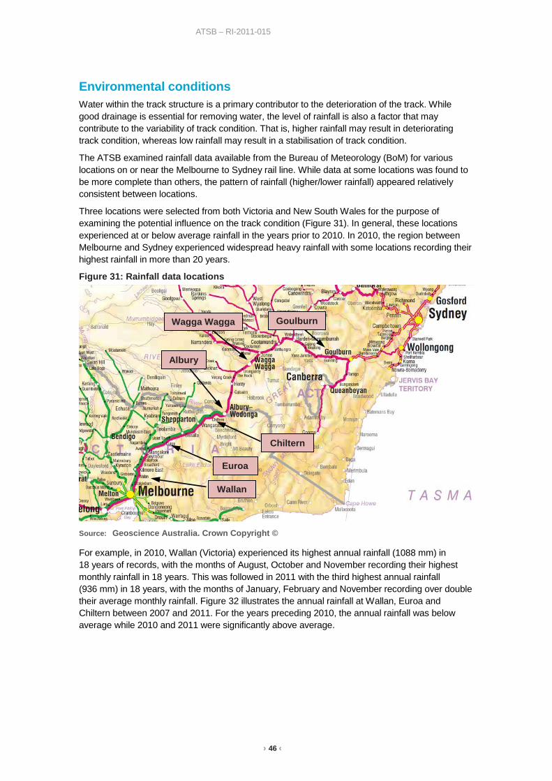
› 46 ‹
ATSB – RI-2011-015
Environmental conditions Water within the track structure is a primary contributor to the deterioration of the track. While good drainage is essential for removing water, the level of rainfall is also a factor that may contribute to the variability of track condition. That is, higher rainfall may result in deteriorating track condition, whereas low rainfall may result in a stabilisation of track condition.
The ATSB examined rainfall data available from the Bureau of Meteorology (BoM) for various locations on or near the Melbourne to Sydney rail line. While data at some locations was found to be more complete than others, the pattern of rainfall (higher/lower rainfall) appeared relatively consistent between locations.
Three locations were selected from both Victoria and New South Wales for the purpose of examining the potential influence on the track condition (Figure 31). In general, these locations experienced at or below average rainfall in the years prior to 2010. In 2010, the region between Melbourne and Sydney experienced widespread heavy rainfall with some locations recording their highest rainfall in more than 20 years.
Figure 31: Rainfall data locations
Source: Geoscience Australia. Crown Copyright ©
For example, in 2010, Wallan (Victoria) experienced its highest annual rainfall (1088 mm) in 18 years of records, with the months of August, October and November recording their highest monthly rainfall in 18 years. This was followed in 2011 with the third highest annual rainfall (936 mm) in 18 years, with the months of January, February and November recording over double their average monthly rainfall. Figure 32 illustrates the annual rainfall at Wallan, Euroa and Chiltern between 2007 and 2011. For the years preceding 2010, the annual rainfall was below average while 2010 and 2011 were significantly above average.
Wagga Wagga Goulburn
Wallan
Chiltern
Albury
Euroa
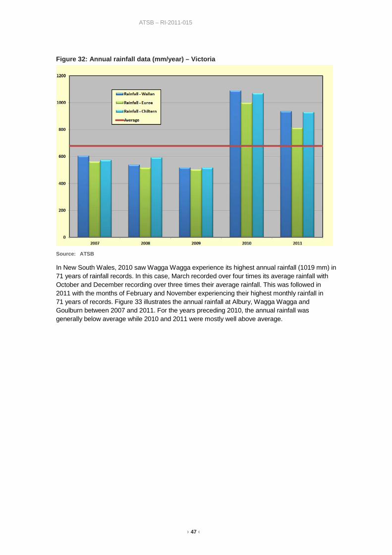
› 47 ‹
ATSB – RI-2011-015
Figure 32: Annual rainfall data (mm/year) – Victoria
Source: ATSB
In New South Wales, 2010 saw Wagga Wagga experience its highest annual rainfall (1019 mm) in 71 years of rainfall records. In this case, March recorded over four times its average rainfall with October and December recording over three times their average rainfall. This was followed in 2011 with the months of February and November experiencing their highest monthly rainfall in 71 years of records. Figure 33 illustrates the annual rainfall at Albury, Wagga Wagga and Goulburn between 2007 and 2011. For the years preceding 2010, the annual rainfall was generally below average while 2010 and 2011 were mostly well above average.
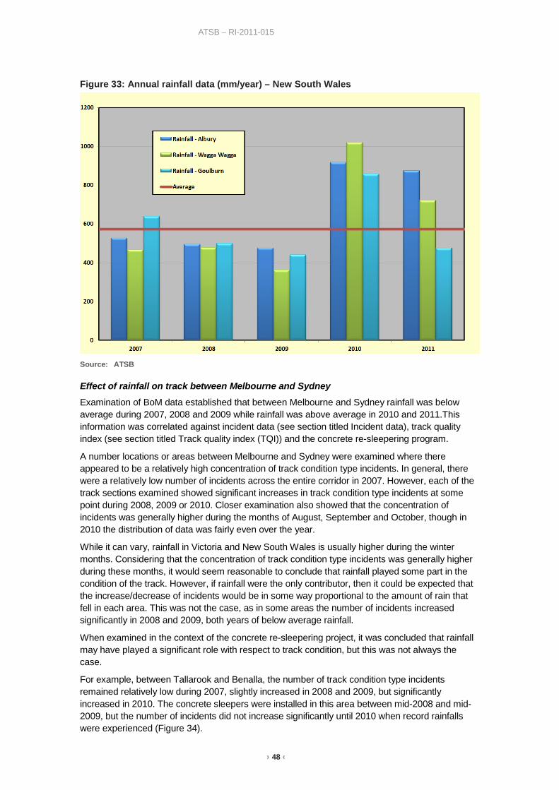
› 48 ‹
ATSB – RI-2011-015
Figure 33: Annual rainfall data (mm/year) – New South Wales
Source: ATSB
Effect of rainfall on track between Melbourne and Sydney
Examination of BoM data established that between Melbourne and Sydney rainfall was below average during 2007, 2008 and 2009 while rainfall was above average in 2010 and 2011.This information was correlated against incident data (see section titled Incident data), track quality index (see section titled Track quality index (TQI)) and the concrete re-sleepering program.
A number locations or areas between Melbourne and Sydney were examined where there appeared to be a relatively high concentration of track condition type incidents. In general, there were a relatively low number of incidents across the entire corridor in 2007. However, each of the track sections examined showed significant increases in track condition type incidents at some point during 2008, 2009 or 2010. Closer examination also showed that the concentration of incidents was generally higher during the months of August, September and October, though in 2010 the distribution of data was fairly even over the year.
While it can vary, rainfall in Victoria and New South Wales is usually higher during the winter months. Considering that the concentration of track condition type incidents was generally higher during these months, it would seem reasonable to conclude that rainfall played some part in the condition of the track. However, if rainfall were the only contributor, then it could be expected that the increase/decrease of incidents would be in some way proportional to the amount of rain that fell in each area. This was not the case, as in some areas the number of incidents increased significantly in 2008 and 2009, both years of below average rainfall.
When examined in the context of the concrete re-sleepering project, it was concluded that rainfall may have played a significant role with respect to track condition, but this was not always the case.
For example, between Tallarook and Benalla, the number of track condition type incidents remained relatively low during 2007, slightly increased in 2008 and 2009, but significantly increased in 2010. The concrete sleepers were installed in this area between mid-2008 and mid-2009, but the number of incidents did not increase significantly until 2010 when record rainfalls were experienced (Figure 34).

› 49 ‹
ATSB – RI-2011-015
In the second half of 2009, the original broad gauge line (west line) was gauge converted and opened for standard gauge traffic. It is possible that the introduction of incident data for the west line may have contributed (in part) to an increase in track condition type incidents during 2010. However, reasonable correlation is evident through 2010 when comparing the profiles of monthly incident data against monthly rainfall data,
On the balance of evidence this would suggest the primary factor influencing the increase in incident rates between Tallarook and Benalla was related to the heavy rains in 2010.
Figure 34: Incident data (Tallarook - Benalla) and Rainfall (Euroa)
Source: ATSB
By comparison the area between Somerton and Wallan shows that track condition type incidents remained relatively low during 2007, but increased significantly in 2008 and remained high during 2009 and 2010. Concrete sleepers were installed in this area between mid-2007 and early 2008, followed almost immediately by an increase of track condition type incidents. High rainfall was not experienced until 2010 (Figure 35).
The balance of evidence would suggest the primary factor influencing the increase in incident rates between Somerton and Wallan was related to the re-sleepering and not so dependent on rainfall events. Re-sleepering of the Somerton to Wallan section was relatively early in the project, however, and during that time the ARTC identified process issues that were then addressed for subsequent work. It is possible that the later onset of track geometry issues in other areas arose principally from high rainfall with re-sleepering of less significance was a result of process improvements identified earlier in the project.
As mentioned in the section titled ‘Drainage’, well-constructed and maintained track should direct water away from the track structure, including water resulting from higher than average rainfalls. Critical to this process is good ballast condition (no fouling) and good formation condition (good shape and cap layer). In the areas examined, track condition type incidents were relatively high following the high rainfall experienced during 2010 and 2011, suggesting that water retention due to fouled ballast was probably a significant contributor to the track geometry issues, rough riding and the development of mud-holes.
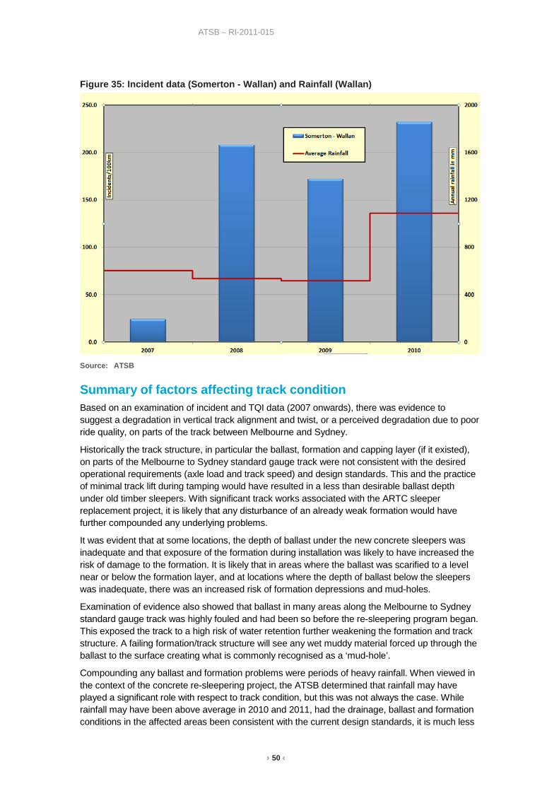
› 50 ‹
ATSB – RI-2011-015
Figure 35: Incident data (Somerton - Wallan) and Rainfall (Wallan)
Source: ATSB
Summary of factors affecting track condition Based on an examination of incident and TQI data (2007 onwards), there was evidence to suggest a degradation in vertical track alignment and twist, or a perceived degradation due to poor ride quality, on parts of the track between Melbourne and Sydney.
Historically the track structure, in particular the ballast, formation and capping layer (if it existed), on parts of the Melbourne to Sydney standard gauge track were not consistent with the desired operational requirements (axle load and track speed) and design standards. This and the practice of minimal track lift during tamping would have resulted in a less than desirable ballast depth under old timber sleepers. With significant track works associated with the ARTC sleeper replacement project, it is likely that any disturbance of an already weak formation would have further compounded any underlying problems.
It was evident that at some locations, the depth of ballast under the new concrete sleepers was inadequate and that exposure of the formation during installation was likely to have increased the risk of damage to the formation. It is likely that in areas where the ballast was scarified to a level near or below the formation layer, and at locations where the depth of ballast below the sleepers was inadequate, there was an increased risk of formation depressions and mud-holes.
Examination of evidence also showed that ballast in many areas along the Melbourne to Sydney standard gauge track was highly fouled and had been so before the re-sleepering program began. This exposed the track to a high risk of water retention further weakening the formation and track structure. A failing formation/track structure will see any wet muddy material forced up through the ballast to the surface creating what is commonly recognised as a ‘mud-hole’.
Compounding any ballast and formation problems were periods of heavy rainfall. When viewed in the context of the concrete re-sleepering project, the ATSB determined that rainfall may have played a significant role with respect to track condition, but this was not always the case. While rainfall may have been above average in 2010 and 2011, had the drainage, ballast and formation conditions in the affected areas been consistent with the current design standards, it is much less

› 51 ‹
ATSB – RI-2011-015
likely that above average rainfall would have resulted in the levels of track deterioration experienced between Melbourne and Sydney.
Much of the undesirable track structure conditions (such as poor formation material, fouled ballast and poor drainage) existed before the ARTC took control and management of the Melbourne to Sydney line. The ARTC advised that they were aware of ballast condition and drainage problems, and had hoped to manage these conditions after the concrete sleepers had been installed. However, it is likely that any underlying (non-visible) structure problems were not known or tested for. It is possible that a more detailed examination of historical data (maintenance records and previous maintenance knowledge or experience) and/or on-site testing may have highlighted any issues and influenced the decisions made prior to the concrete re-sleepering works. Similarly, it could have been anticipated that multiple years of below average rainfall would, at some time, be replaced by average or possibly above-average rainfall. Having been aware of the poor ballast condition and drainage problems, the ARTC should also have been aware of the increased risks associated with the possibility of increased annual rainfall.

› 52 ‹
ATSB – RI-2011-015
Long term remediation work As discussed in the section titled ‘Track condition and safety’, the guidelines for treatment of mud-holes involved a combination of interim (short term) treatments and corrective (long term) treatments. Since longer term treatments aim to achieve permanent solutions, it is important to understand the cause of the problem. As mentioned previously, rough track reported as mud-holes can have multiple causes, such as soft or damaged formation, fouled ballast, inadequate ballast or inadequate drainage. Consequently, the appropriate method of remediation is also likely to vary. Long term treatments include:
• Ballast shoulder cleaning or replacement. This involves removal of the ballast shoulder (the section outside the sleeper ends) using either an excavator or dedicated track mounted ballast cleaner. The ballast is replaced with new ballast or the existing ballast is cleaned (fine material contamination removed) and then replaced. The track is then tamped to correct any geometry problems. The process may need to be repeated a number of times, as the ballast may become fouled with the fines that leach out from areas of the ballast bed that were not cleaned.
• Full section ballast replacement. This involves removal of ballast from around and under the sleepers using either an excavator, dedicated track mounted under-cutters or a process called ‘sledding’47. The ballast is replaced by new ballast and the track tamped to correct any geometry problems. This process has a better opportunity to ensure adequate ballast depth and in some cases (depending on equipment and process) may help provide an appropriate cross fall to allow water to drain freely towards the side drains.
• Regardless of any treatment to the ballast, drains should be provided to direct water away from the track structure. The drains may require additional work to ensure they are free draining with no opportunity for ponding.
Ballast shoulder cleaning (or replacement) is far cheaper than full section cleaning and less disruptive to train operations, but it does not address problems such as inadequate ballast depth (under sleepers). While the treatments listed above may address most mud-hole related problems, they may not be as effective if the cause is related to more deep seated formation problems (soft or damaged formation). In this case, more extensive excavation and track rehabilitation work may be required which may or may not require removal of the track.
Long term treatments applied to the Melbourne to Sydney track
Consultants engaged by the ARTC considered both ballast shoulder cleaning and full ballast cleaning as options for remediation, but concluded that funding arrangements could not sustain a full ballast cleaning program. Consequently, it was recommended that a program of ballast shoulder cleaning be adopted.
Following heavy rainfall in 2010, the ARTC introduced an accelerated program of track remediation. While considerably more expensive, there were some locations where the ARTC decided that full section ballast replacement was required. Both undercutting and sledding processes were adopted. Undercutting and sledding involves the removal of fouled ballast before new ballast is added and the track tamped to ensure the correct track geometry.
An undercutter can be either a dedicated track machine or an excavator mounted attachment. Both options effectively use a horizontally mounted chain digger to remove the fouled ballast from underneath the railway track so that fresh clean draining ballast can be substituted. Figure 36 illustrates a track mounted excavator conducting under-cutting remediation works on the Melbourne to Sydney track.
47 Sledding involves dragging a sled under the sleepers which directs the ballast out from under the sleepers.

› 53 ‹
ATSB – RI-2011-015
A sled is a plough frame that is placed under the sleepers at a point where ballast has been excavated. The frame is then pulled by a locomotive (or other suitable machine) so that the plough shape ejects the fouled ballast from under the sleepers as the sled is dragged along.
Figure 36: Remediation work – track under-cutting
Source: ATSB
In addition to resolving the fouled ballast problems, the ARTC also implemented works to address other drainage problems. For example, works were conducted to ensure the correct fall of ground away from the track structure and the repair/maintenance of existing drains or the installation of new drains.
Limitations to remediation works As discussed earlier, short term remediation is intended to attenuate the effect of track related problems while long term treatments are aimed at a permanent solution. The approach should be effective provided the long term treatments are implemented to correct underlying track geometry problems arising from fouled ballast, poor drainage and weak/soft or damaged formation.
The remediation works applied to the Melbourne to Sydney track are likely to address fouled ballast and drainage problems, but the effectiveness of the treatments may be limited when potential problems with the formation are also considered. While undercutting and sledding may provide adequate ballast depth to ensure loads are appropriately distributed, it cannot fully compensate for inadequate or poor formation.
To address problems associated with poor formation material, the old material needs to be removed and the formation rebuilt to the specified standard. This requires extensive track closures and earthworks. If the poor formation material is to remain, action should be taken to ensure the material can adequately support the load. For example, a process of lime slurry injection has been

› 54 ‹
ATSB – RI-2011-015
successful at strengthening weak formations48. Alternatively, it is possible for poor formation material to support the applied loads, providing a suitable capping layer is included to assist with the distribution of load and the protection of the poor material from the effects of water penetration. The alternative solutions should also be accompanied by appropriate inspection and maintenance regimes to ensure the formation remains sound.
Although a capping layer is usually included in new construction it does not commonly exist in old tracks and cannot be easily placed or replaced after undercutting or sledding operations. However, on the Melbourne and Sydney line where fouled ballast has built up over time, the ballast material that remains after undercutting operations may perform some of the functions of the capping layer. For example, water does not drain efficiently through fouled ballast (a disadvantage for the ballast layer), but as a capping layer this may be a benefit because it may provide some level of protection to the formation providing an appropriate grade is included to encourage water to run away from the track structure.
While an appropriate grade (away from the centre of the track) may be achievable through skilful operation of the undercutter, the same result may not be possible with sledding. Without an appropriate grade, water is more likely to become trapped on top of the capping layer before soaking through to the formation material. If inadequate action is taken to replace or improve the formation, soft formation problems are likely to remain, regardless of good, well-draining ballast. Given time, progressive failure and development of ballast pockets (and/or mud-holes) are likely to continue with a corresponding requirement for an increased regime of track maintenance.
Summary of remediation work The ARTC has applied a number of track remediation strategies aimed at a permanent solution to the problems that developed between Melbourne and Sydney. These have included ballast shoulder cleaning or replacement, full section ballast replacement and drainage repairs or improvements. The remediation methods adopted included a combination of undercutting and sledding for addressing fouled ballast and inadequate ballast depth problems, plus track works targeting the correction of general drainage problems.
While the treatments applied to date are likely to correct most ballast depth, fouled ballast and drainage problems, the treatments are unlikely to correct the more deep seated formation problems such as inadequate materials or soft, damaged formation.
At locations where the formation may be deficient, it is likely that water will continue to soak through to the formation material thereby continuing to weaken the structure. Regardless of a good layer of ballast, it is possible that some locations may continue to develop ballast pockets, mud-holes and geometry defects, with a corresponding requirement for an increased regime of track maintenance.
48 Wilkinson, A., Haque, A., Kodikara, J., Adamson, J., Christie, D. – Improvement of Problematic Soils by Lime Slurry
Pressure Injection: Case Study, 2010

› 55 ‹
ATSB – RI-2011-015
Safeworking – Work on track With the significant amount of track work being conducted on the Melbourne to Sydney rail line, there has been an increased exposure to safeworking incidents involving track maintenance activities. In accordance with the Minister’s request, the ATSB examined the safeworking practices in relation to the track. Specifically, a number of reported incidents were examined to identify if there were any significant issues associated with the safeworking practices.
A railway safeworking system is defined as an integrated system of operating procedures and technology for the safe operation of trains and the protection of people and property on or about the railway49. The safeworking system uses ‘Authorities’ to manage the conditions under which trains, track machines and workers access the track.
For the part of the Melbourne to Sydney track operated by the ARTC50, authorities for train operations and maintenance activities are managed by Network Control Officers (NCOs) located at the ARTC’s Junee network control centre. The safeworking system used to manage train operations incorporates track circuiting for vehicle detection and colour light signals to indicate the authority to proceed. Remote control and monitoring of field signalling equipment is achieved using a Phoenix control system, a non-vital51 CTC52 system that provides real time monitoring and control of field hardware including signals, points, track circuits and the associated management of train movements.
The signalling and CTC system is not designed to detect and monitor track workers and some track machines. Consequently, additional rules and procedures are applied for track maintenance activities. For work on track, authorities are communicated by phone or radio before track vehicles, workers and their equipment are permitted to occupy defined sections of track.
Signal blocking facilities When track works are to be undertaken using equipment and machinery it is essential that processes are implemented to ensure an unexpected train does not enter the worksite. For track works between Melbourne and Sydney, authorities are issued (Track Warrant in Victoria and Track Occupancy Authority in New South Wales) for worksites located within track sections defined by controlled signals. The worksite is protected by the NCO applying blocking facilities53 to the track section entry signals, thereby preventing rail traffic from obtaining signal authority to enter the portion of track covered by the work authority. The blocking facilities are not to be removed until the track has been confirmed as clear and safe for normal traffic, and the work authority has been fulfilled.
In 2011/12, there were two incidents reported to the ATSB where blocking facilities had been removed from signals protecting an active worksite. For one of the incidents, a train received signal authority to enter the track section where a worksite was still operational.
49 Source: National Guideline Glossary of Railway Terminology (www.rissb.com.au). 50 In New South Wales, the ARTC manages the line between Albury and Macarthur (outer metropolitan Sydney). 51 Non-vital: Signalling equipment and circuits are considered non vital where failure to function correctly would not cause
an unsafe outcome of the signalling system. Non-vital equipment and circuits do not affect the safe operation of the signalling system. Source: National Guideline Glossary of Railway Terminology (www.rissb.com.au).
52 Centralised Traffic Control (CTC): A system of remotely controlling the points and signals at a number of interlocked stations, junctions and crossing loops in automatic signalling areas, from a centralised control room or signal box. Source: National Guideline Glossary of Railway Terminology (www.rissb.com.au).
53 A ‘Block’ is a facility used to prevent the unintended clearing of a signal or issue of a proceed authority.

› 56 ‹
ATSB – RI-2011-015
Seymour, Victoria – 25 July 2011
At about 1350 (EST), a V/Line passenger train, having received authority (signal indication) to depart Seymour station, approached a worksite obstructing the track. The workers moved to a place of safety as the train driver made an emergency application of the brakes and stopped about 20 m from the worksite. There were no injuries or damage to rolling stock or infrastructure.
Information provided to the ATSB indicated that at about 1000, two Track Warrants were issued for track work to be undertaken on both the east and west tracks near Seymour. The work on the east track was completed by 1300, the Track Warrant was fulfilled and the relevant blocking facilities removed. Work on the west track had been authorised to continue until about 1500. However, at about 1338, the NCO removed the blocking facilities from the west track while setting up a route for the V/Line passenger train. With no blocking facilities applied, the NCO was able to clear a signal at Seymour which authorised the train to travel on the west track towards the active worksite.
The incident was investigated by the Chief Investigator, Transport Safety (reference 2011/08). The investigation report stated that a specific reason for the network controller’s error could not be determined, but noted that there were inadequate system defences to prevent both the controller’s error and the hazardous outcome resulting from it. As a result of this incident the regulator imposed a number of conditions on ARTCs accreditation to restrict track work and require ARTC to enhance risk control for work site protection using track warrants. The ARTC subsequently introduced further controls in the train control centre at Junee and a new track based warning device.
Harden, New South Wales – 27 April 2012
At about 1506 (EST), the blocking facilities protecting a worksite near Harden were removed while the worksite was still active. The error was quickly identified and the blocks reinstated. There were no trains in the vicinity.
Information provided to the ATSB indicated that two Track Occupancy Authorities (TOAs) were issued for track work either side of Harden. At about 1220, TOA 46 was issued for work on the Down Main between Yass Junction and Harden. About 30 minutes later, a second TOA (47) was issued for workers to occupy the Down Main between Harden and Cootamundra. Blocking facilities were applied to signals at Yass Junction (protecting the worksite under TOA 46) and Harden (protecting the worksite under TOA 47).
At about 1506, the Protection Officer (PO) working between Harden and Cootamundra (TOA 47) contacted the NCO to fulfil the TOA. However, he communicated the wrong TOA number which resulted in TOA 46 being fulfilled and the blocks on the signals at Harden being removed. Shortly after, the NCO noticed that the Down Main between Yass Junction and Harden was still occupied, so he replaced the blocks on the signals at Harden. The NCO contacted the PO and it was found that the PO had mistakenly written number 46 on the TOA form instead of the correct number 47.
Examination of the voice logs found that at the time the TOA was issued, the NCO communicated the correct number (TOA 47) to the PO and the read-back by the PO also communicated the correct TOA number. There was no clear explanation as to why the incorrect number was written on the TOA form.
Summary of signal blocking facilities In both incidents, there were two worksites adjacent to each other. Both had been issued the appropriate authorities and the blocking facilities were applied to the relevant signals. However, when one authority was fulfilled, the wrong blocks were removed (Harden) or the blocks were removed when still required (Seymour), leaving the remaining active worksite vulnerable to unexpected train movements.
› 57 ‹
ATSB – RI-2011-015
Examination of the safeworking rules and procedures indicated that they protected workers, provided each step of the process was followed without error. However, the procedures were susceptible to a single, undetected error increasing the safety risk.
For example, for the incident near Harden, the initiating error was by the PO. The process required the PO to communicate the “correct TOA number”, but there was no process in place for the NCO to verify that the TOA number provided was in fact correct. There was no requirement to communicate information such as worksite location or signal numbers that were protecting the worksite, so there were no prompts that may have indicated to the NCO that the TOA being fulfilled was the correct TOA. As a result of the Seymour incident, the regulator imposed a number of conditions on ARTC. The ARTC has implemented changes to its Phoenix control system which now requires the use of a code to ensure that the correct block is removed and has improved the information required to impose the block in the first instance.
Joint occupancy TOAs (New South Wales) A TOA gives track workers exclusive occupancy to a defined section of track for an agreed time period, but may allow joint occupancy under defined exceptions. A joint occupancy condition can occur when a TOA to occupy a section of track is requested, but a train has already entered that same section of track. Under these conditions, a TOA may still be issued providing the NCO verifies that the train has already passed the proposed worksite or the track access point. If the train is yet to pass the worksite, the TOA cannot be issued until the worksite PO has observed the relevant train pass the worksite location and has told the NCO the identification number for the lead unit of the train.
In 2011/12, there were two incidents on the Melbourne to Sydney track reported to the ATSB where a TOA had been issued, but a train was still travelling towards the worksite location.
Fish River, New South Wales – 10 July 2011
At about 0706 (EST), a TOA was issued to the PO of a worksite located at Fish River (about half way between Yass Junction and Goulburn) after the PO had correctly identified the lead unit of train 8938 as having passed the worksite location. About four minutes later, the NCO realised that he had issued the TOA while another train (number 8138) was also within the track section but had not yet passed the worksite at Fish River.
Both the PO and the driver of train 8138 were contacted. The train was brought to an immediate stop while the PO cleared the worksite and fulfilled the TOA so that train 8138 could continue its journey.
Harden to Yass Junction, New South Wales – 22 March 2012
At about 1254 (EDT), train 3924N struck the detonators54 protecting a worksite between Harden and Yass Junction. The driver stopped the train before entering the worksite. There were no injuries or damage to rolling stock or infrastructure.
Information provided to the ATSB indicated that a PO had contacted Junee network control centre at about 1224 and requested a TOA for work to be carried out on the Up Main between Harden and Yass Junction. The PO identified the lead unit of train 3992N as locomotive EL57 and advised the NCO that the train had passed the proposed worksite. The NCO acknowledged the correct identifier for train 3992N and applied blocks to the signals at Harden. The TOA was issued at about 1228.
However, the NCO did not notice that a second train (3924N) had also entered the Harden to Yass Junction section about 10 minutes earlier and was still travelling towards the worksite. When 54 A detonator is a device that explodes on impact used to warn drivers and track vehicle operators of the condition of the
track ahead.
› 58 ‹
ATSB – RI-2011-015
the train approached the worksite, it had already slowed for a 40 km/h temporary speed restriction before running over the detonators protecting the worksite, so it was able to stop well before entering the work area.
Summary of joint occupancy TOAs In both incidents, the NCO did not notice that more than one train was within the section covered by the TOA. This condition is not uncommon because many of the track sections can extend over significant distance. For example, Yass Junction to Goulburn is about 94 km long and Harden to Yass Junction about 68 km. These distances and the signalling system provide ample capacity and opportunity for multiple trains to be within the section at any one time.
While it is clear that the NCO must not issue a TOA unless any trains within the section have been verified as having passed the proposed worksite, it is evident that errors can still occur. In these cases, the POs had installed additional site protection in the form of flags and detonators, so a second level of defence existed. However, the incidents highlight the importance of the NCO ensuring the track section covered by the TOA is clear of trains, or all trains have passed the proposed worksite, before the TOA is issued.
Examination of the safeworking rules and procedures indicated that they protected workers provided each step of the process was followed correctly. While the procedures were vulnerable to the consequences of single, undetected errors, the risk was mitigated by additional site protections.
Working outside the limits of authority When an authority is to be issued for track work, there are specified requirements for defining the limits between which the work is to be conducted. For example, the Melbourne to Sydney line is remotely controlled by fixed signalling, so the limits of TOAs issued in New South Wales are defined by ‘Yard Limits’ (often determined by the controlled signals for the yards either side of the proposed worksite). Workers are not authorised to access or obstruct the track outside the defined limits of their authority.
In 2011/12, there were two incidents on the Melbourne to Sydney track reported to the ATSB where a TOA had been issued, but workers obstructed the track outside the defined limits of their authority.
Harefield, New South Wales – 26 April 2012
At about 1448 (EST), a train entered the yard at Harefield and was required to stop because of an unexpected red flag positioned in the middle of the track. The red flag had been placed on the track as protection for workers cleaning culverts within the Harefield Yard. However, the TOA had been issued for work between the Harefield and Junee yard limits, not within the Harefield Yard itself. The workers were working outside the limits of their authority.
Cootamundra West, New South Wales – 23 November 2011
At about 1230 (EDT) a track machine (tamper TJ090) operating under a TOA exceeded its authority by approximately 800 m. The TOA authorised the track machine to occupy the track up to the Cootamundra yard limits. However, the operator of the track machine passed the yard limit and pulled up at the Cootamundra West platform. The track machine had moved beyond the limits of its authority.
Summary of working outside the limits of authority In both incidents, workers had been authorised to undertake work on track between defined limits, but they had moved beyond the limits and obstructed the track without authorisation.
Examination of the safeworking rules and procedures indicated that they protected workers so long as each step of the process was followed correctly.
› 59 ‹
ATSB – RI-2011-015
Miscellaneous safeworking incidents Frampton, New South Wales – 28 September 2011
At about 0743 (EST), a crew member of train 7R02 reported that machines were working on the down main line near the 445 km track location, but no additional track protection had been place on the up main line. It was subsequently identified by the ARTC that the protection officer was in breach of the rules and procedures by not having the adjacent line protected.
While not directly placing the workers at risk of a train entering the worksite, the omission of protection measures on the adjacent line did increase the safety risk for workers if they happened to be close to the adjacent running line. Similarly, adjacent line protection also provides protection against worksite obstructions for trains operating on the adjacent track.
Bomen, New South Wales – 6 September 2010
At about 2307 (EST) the NCO attempted to clear a signal for freight train 2CM3 to depart Bomen Yard and proceed onto the mainline towards Melbourne. The NCO was unable to clear the signal, so he gave verbal authorisation for the train to pass the signal while it was displaying a stop indication. However, issuing a verbal authorisation was not in compliance with the safeworking rules in this case and the NCO should have issued a written Special Proceed Authority (SPA).
The rules and procedures only permit verbal authorities to be issued for train movements with the yard limits. Where a movement is required to pass a signal at stop and travel beyond the yard limits, a written authority is required which includes a number of checks and assurances that it is safe to do so. In this case, the verbal authorisation did not result in an unsafe condition, but under different circumstances, the omission of the SPA checks and assurances may increase the safety risk.
Summary of miscellaneous safeworking incidents These incidents occurred where a worker had either not fully completed each step required by the rules or had applied a process not permitted by the rules.
In both cases, the rules provided for safe operations if followed correctly, but if procedures or steps were omitted through error, an increased risk to safety may develop.
Summary – Safeworking practices The safety of railway operations has always been dependent on human actions with a strong relationship between human error and a major accident. Historically, the rail industry has progressively implemented technical solutions to manage the risk of human error, often driven by an occurrence involving the loss of life. The vast majority of technical solutions have been directed towards train operations and the requirement to ensure no two trains occupy the same section of track. For example, signal interlocking systems and ultimately, full automatic train control.
However, technical solutions are less common in relation to work on track, where rules and procedures are expected to be strictly obeyed to manage the safety risk. In the absence of a technical solution, safeworking in relation to work on track will continue to be vulnerable to human error. Consequently, risk reduction requires either the removal of the hazard entirely or the implementation of additional countermeasures so that no single error can result in an immediate unsafe environment.
A considerable amount of track work was conducted on the Melbourne to Sydney track due to the deteriorated track, re-sleepering project and track rectification works. While a number of safeworking incidents were reported to the ATSB at various times between 2009 and 2012, a decision was made not to conduct full investigations because, in isolation, the information provided suggested that no new lessons would be learnt that would improve the safety of the railways.

› 60 ‹
ATSB – RI-2011-015
The ATSB examined a number of the reported incidents to identify if there were any significant issues associated with the safeworking practices. In general, it was found that the safeworking rules and procedures protected workers provided each step of the process was followed correctly. However, some of the incidents examined highlighted that methods for accessing the track were susceptible to human error, either through mistake or violation. In some cases, the safeworking systems were vulnerable to a ‘single point of failure’ which could increase the risk to rail safety.
The ARTC, in consultation with rail safety regulators, has implemented changes to their systems for safely managing work on track and help protect against human error. For example, the ARTC has implemented changes to better manage worksite protection and added functionality to its Phoenix control system to better manage the application and removal of blocking facilities.
› 61 ‹
ATSB – RI-2011-015
Systemic review of safety systems The Minister requested that the ATSB conduct a review the safety systems associated with the track between Melbourne and Sydney, including signalling and the quality assurance of work undertaken on the track. Through various discussions with rail operators, a number of issues were raised with respect to the railway signalling system, the application of temporary speed restrictions, management of train control reports, general infrastructure maintenance and whether these systems were safe and fit for purpose.
In particular, a number of concerns were raised in Victoria regarding differences in the signalling design principles applied to new signal layouts when compared to other areas within Victoria. The concerns included signal sighting, the type of signal lamp, the height of signal masts, the positioning of signal lamps on the signal masts and the location of trackside signals.
Signalling system As part of the ARTC North South Corridor Strategy, the broad gauge track between Seymour and Wodonga (Victoria) was converted to standard gauge and incorporated into the Melbourne to Sydney rail corridor. The signalling design and layout in New South Wales remained largely unchanged whereas in Victoria the project included re-signalling to allow bi-directional working55 on both tracks between Seymour and Wodonga. In addition, a number of passing lanes56 were installed on the single track sections between Melbourne and Seymour (Victoria), and between Albury and Junee (New South Wales). The aim of the project was to ease network congestion and improve transit times between Melbourne and Sydney.
The greater change having occurred in Victoria is probably the reason behind concerns being expressed regarding the signalling system in Victoria. The concerns were mostly expressed by drivers and operators that only operated between Melbourne and Albury and not so much from drivers operating in New South Wales.
Railway signalling
Given the size and weight of most trains, braking distance can be considerable. Therefore, trains need to be driven several kilometres ‘in advance’ such that a train driver will start slowing a train some considerable distance before the required stopping point. Railway signalling systems have evolved over the years, but the basic philosophy has not changed:
• Maintain a safe distance between following trains on the same track. • Safeguard the movement of trains at junctions and when crossing the path of another train. • Regulate the passage of trains according to the required service density and speed. In achieving this requirement it is essential that signalling systems provide relatively simple and clear information to drivers. Train drivers operating over the Melbourne to Sydney rail corridor control the movement of their train in accordance with information provided by colour light signals57 located alongside the track. Documented network rules define driver actions in response to the information provided by signal indications.
55 Allowing for normal travel in either direction according to the infrastructure and system of safeworking in use. Source:
National Guideline Glossary of Railway Terminology (www.rissb.com.au) 56 Long sections of double track allowing trains to pass at speed. 57 There are various types of railway signalling systems in existence but the majority of contemporary systems and in
particular those on the Melbourne to Sydney corridor use colour light signals, similar to traffic light signals, to convey information to train drivers.

› 62 ‹
ATSB – RI-2011-015
Railway signalling systems provide information grouped into three key actions:
• Clear – trains may proceed past the signal with no additional restrictions. • Caution58 – trains may proceed past the signal, but expect the next signal to be at a more
(Warning) restrictive aspect, such as reduced speed or stop. • Stop – trains must stop at the signal. The signalling system is configured to provide sufficient information in advance, so that the driver has enough warning to control the train and stop at the required location. The ‘Caution’ signal is critical because it advises the driver that the next signal is at ‘Stop’ and the train must be slowed to stop before the next signal (target stopping point).
From a design perspective the minimum distance between a caution signal and a stop signal should be no less than the braking distance of the train that takes the longest distance to stop. Sighting distance is a nominal point at which the caution signal can be clearly observed by a driver before commencing a brake application to stop the train at the stop signal (Figure 37).
Figure 37: Sighting distance
Source: ATSB
If signals are positioned appropriately, the driver of a train approaching a caution signal will see, interpret and act before passing the signal. Stopping the train should be achievable because the distance between signals is based on train braking distance.
For the Melbourne to Sydney line, signal spacing is based on the braking performance of a specific class of train, a Superfreighter. On a level grade at a maximum speed of 115 km/h, the braking distance of a Superfreighter is about 2.2 km59. Sighting distance is based on providing a driver with a minimum of an 8 second view of the signal while travelling at line speed60. In this case, it is based on an XPT passenger train travelling at 160 km/h (the fastest permitted speed between Melbourne and Sydney). The minimum required sighting distance equates to about 356 m.
On the Melbourne to Sydney line, indications are displayed using colour light signals. However, due to the legacy of Australian rail operations (State based rules and procedures) there are differences between the signalling systems in use throughout Victoria and New South Wales. In Victoria, the system is known as ‘Speed Signalling’, while in New South Wales, the system is known as ‘Route Signalling’.
Under route signalling, signals indicate to the driver what route the train will take after passing the signal. This is achieved by a lower turnout unit61 attached to the signal. The driver uses his route
58 The term ‘Caution’ is used in this report, but is referred to as a ‘Warning’ in Victoria. 59 ARTC document EDS-32-01, Signalling rolling stock interface, table GW40. High speed passenger trains (XPT) are
noted in EDS-32-01 as having improved braking performance and are permitted to travel at higher track speeds, even when approaching signals.
60 ARTC document ESC-04-01, Signal sighting and position. 61 A diagonal row of yellow lights angled up towards the turnout route.

› 63 ‹
ATSB – RI-2011-015
knowledge (sometimes reinforced by permanent speed restriction signs) to drive the train at the correct speed for the route indicated.
Under speed signalling, the driver is informed of the maximum permissible speed, not route information. Speed signalling removes some of the importance of driver route knowledge, but generally requires a greater range of signal aspects to provide the information. Table 2 illustrates examples62 of the mainline signals on the Melbourne to Sydney line.
Table 2: Main line signals59
Victoria (see note 1) New South Wales (see note 2)
Stop
Rail traffic must stop before passing the signal.
Rail traffic must stop before passing the signal.
Caution/Warning
(Note 3)
The track ahead is unoccupied and may be travelled at normal speed, but the driver must be prepared to stop at the next signal.
The track ahead is unoccupied and the next signal may display a stop indication.
Clear
(Note 3)
The track ahead is unoccupied and may be travelled at normal speed..
The track ahead is unoccupied and the next signal displays a proceed indication.
Notes:
1. The upper signal head displays normal speed indications. The lower signal head displays medium speed indications. A third signal head is provided where a low speed indication is required. Only the common normal speed indications are illustrated.
2. The lower signal head indicates the turnout route by displaying a diagonal row of yellow lights angled up towards the turnout route.
3. Signal indications other than Stop are referred to as ‘Proceed’ indications in New South Wales
Signal sighting Trackside signals are the primary conduit for providing information to drivers about the appropriate actions required to ensure safe passage of rail traffic. One of the more significant operational risks to rail safety occurs when a train passes a signal without the driver having seen, interpreted or acted in accordance with the signal indication. The most severe occurrence is a train passing a signal displaying a stop indication (commonly termed as a ‘Signal Passed at Danger’ or a SPAD). 62 Only the Stop, Caution/Warning and Clear signals are illustrated for the purpose of explaining some concepts in the
following sections of the report.

› 64 ‹
ATSB – RI-2011-015
While many factors may contribute to a SPAD, good signal sighting is an essential precursor to minimising the risk of a SPAD occurring.
Many organisations around the world have conducted studies into SPAD causes and mitigation, but the work done in the United Kingdom (UK) by the Rail Safety and Standards Board (RSSB) is probably one of the more extensive. While train operations in rural Australia may be significantly different to those in the UK, the work associated with SPAD mitigation is still relevant and provides a good reference point for examining what would be recognised as an acceptable practice for signal sighting.
The RSSB is responsible for developing and maintaining rail standards in the UK through facilitating cross-industry research and development. The RSSB published document that provides guidance on the requirements for positioning signals to ensure adequate viewing and clarity of meaning for drivers is Guidance Note GE/GN8537, Guidance on Signal Positioning and Visibility. The RSSB guide states that signals shall be positioned and aligned to ensure that:
• the driver of an approaching train has sufficient time to identify, observe and interpret the information being displayed
• the information being presented is clear and unambiguous • the risk of reading the wrong signal is minimised • the presentation of information displayed to the driver is such as to avoid information overload. The RSSB guide notes that the process of selecting the position, form and alignment of signals is complex and an ideal arrangement may not always be possible due to real-world complications. Consequently, an individual assessment should be conducted for sighting of each signal to ensure that any deviation from the ideal does not introduce intolerable risk. Consistent with the principles described in the RSSB guide, the ARTC facilitates a Signal Sighting Committee with representation from all stakeholders (rail operators). The fundamental role of the Signal Sighting Committee is to determine if the signals, as designed and installed, can be seen clearly, be distinguished from other signals and are ‘fit for purpose’.
As the North South Corridor project progressed, there were a number of concerns raised by rail operators participating on the Signal Sighting Committee. A key Victorian stakeholder believed that a difference in the proposed signalling design principles for the North South Corridor, when compared to other areas within Victoria, compromised the safety of the railway. These concerns were also communicated by the regulator (Public Transport Victoria). Most of the concerns were associated with signal sighting.
Negotiations between the ARTC and the stakeholder failed to reach an agreement, so an independent and impartial assessment was conducted by Lloyd's Register Rail Limited. The areas identified as requiring independent review included:
• Signal sighting • Signal heights • The separation between A (normal speed) and B (medium speed) signal lights • The use of signals on right hand side (RHS) of track, and • Foreseeable driver errors, memory lapses and inattention. The assessment aimed to identify any safety implications and to help resolve the differences of opinion and progress the accreditation process.
› 65 ‹
ATSB – RI-2011-015
Signal lamps
The type of signal lamp proposed by the ARTC was a medium spread LED signal lamp, specified (by the manufacturer) as providing a typical sighting distance of 600 m against a bright skyline63. The rail operator requested that intermediate LED signal lamps be installed, providing a typical sighting distance of 1500 m against a bright skyline.
The ARTC standard for sighting distance states an optimal sighting distance equal to 10 seconds viewing at line speed, but allows for a minimum of 8 seconds. This is consistent with the standards of other rail networks in Australia and overseas, which specify ranges varying between 6 and 10 seconds for signal sighting. For the Melbourne to Sydney track, the specification equates to a distance of about 356 m at 8 seconds and about 444 m at 10 seconds for the fastest service (XPT passenger service travelling at 160 km/h).
Based on these sighting distances, the installation of medium spread LED signal lamps, providing a typical sighting distance of 600 m, would appear reasonable. This would be more so in Victoria, where a maximum train speed of 130 km/h is specified for trains classified as ‘Super premium’ (XPT)64. At 130 km/h, a distance of 600 m provides about 16 seconds of signal sighting, double the minimum specified in the ARTC standards.
The RSSB guide states that the use of a minimum reading time is common, should not be less than 8 seconds, but may be increased where there is an increased likelihood of misread or failure to observe. The guide goes on to highlight that a signal can fulfil two basic roles. It could be a ‘Stop’ signal identifying the end of the authority, or it could be a ‘Distant’ signal warning of another signal ahead that is serving as a stop signal. A signal could also provide both functions.
With respect to sighting distance, the RSSB guide states that:
The driver’s requirement for viewing a distant signal is primarily at long range so as to give good warning of the action to be taken and with time to re-check the aspect information, if necessary.
The driver’s requirement for viewing a stop signal is primarily at close range to permit accurate control of the train speed to a stop.
The RSSB guide states that providing a sufficient reading time is a complex issue and an understanding of human factors issues is an important part of assessing the suitability of a proposed signal configuration. In general, an individual assessment should be carried out for each signal to determine if there are any site specific hazards that may require a different sighting distance.
The RSSB guide also provides some discussion specifically in relation to signal intensity. The guide states that signal intensity designed for daylight conditions may dazzle drivers in night-time conditions. It also cautions that the issue may be a particular problem with the new LED signals, the luminance intensity of which is greater than traditional filament bulbs.
The independent assessment by Lloyd's Register Rail considered arguments both for and against the installation of intermediate LED signal lamps. A study on human factors in signalling systems suggested that (in train driver simulated environments) if you give drivers the information they want at the time they need it they perform better, while if you give them that information too early or too late they don't perform as well65. In addition, research suggested that providing increased sighting distance may add to visual clutter and the potential for read through errors66: that is, a 63 It should be noted that a manufacturer’s specification of typical sighting distance does not mean that the signal is not
visible at further distances. 64 ARTC document, TA02 – Network interface co-ordination plan. 65 Mashour (1974) Human Factors in Signalling Systems 66 IRSE, April 2001, Report 3 -·The Influence of Human Factors on the performance of Railway Systems, and IRSE
signalling philosophy review, report of working group 2

› 66 ‹
ATSB – RI-2011-015
driver may react to an indication presented by a signal that was some distance beyond the signal that was relevant at the time.
However, the assessment recognised that the research was based on a simulated environment that was very different to the driving environment in Australia. On the Melbourne to Sydney line, signals are typically spaced at distances greater than 2 km, effectively removing the risk of read through errors. In some cases, trains may travel considerable distances without regular signal indications, creating a driving environment that is relatively devoid of driving task stimulation. Consequently, it was considered important for signals (when they do occur) to be visually prominent so that drivers can clearly detect and recognise the signal indications.
Lloyd's Register Rail concluded that longer periods of viewing opportunity were particularly important for distant signals where trains had been travelling for long periods since a previous signal indication. Their recommendation was for intermediate LED signal lamps to be installed at distant signals to support longer sighting times. The ARTC responded by committing to the installation of intermediate LED signal lamps on distant signals between Seymour and Wodonga.
Signal height
The ARTC specification for signal height stated that the nominal height of the signal main red indication should be in line with the driver’s eye position, quoted at 4.2 metres above rail level. Since the signals in Victoria consist of two signal heads (normal and medium speed), the height of the upper red indication was specified at 4.5 m and the lower at 3.0 m. Some signals also include a low speed signal head specified at 2.0 m above rail level and some include a speed indication that was to be located above the upper signal head. Driver representatives of the rail operator requested that the height of the upper signal main red indication should be 6.0 m. The representatives also requested a 2.0 m separation between signal heads (discussed further in the section titled Signal light separation).
The RSSB guideline states that the ideal height for the most restrictive aspect of a signal is the driver’s eye level, but acknowledges that alternative heights may be appropriate for some signals. For the UK, the accepted standard is for signals to be as close as possible to 3.3 m above rail level, but may be up to 5.1 m if required for adequate visibility67. If the signal was to be positioned higher than the driver’s eye level, consideration should be given to its readability when approaching the signal and its readability when the driver is close to the signal. For close-up viewing, the RSSB guide states that all elements of the signal shall be continuously viewable from a distance of about 40 m from the signal to the stopping point, usually about 15 m from the signal68. The guide emphasises that the signal must be visible and prominent from the normal driving position.
The vertical field of vision for a train driver is limited more by cab design than the capability of the human eye. The Lloyd's Register Rail report shows the vertical field of vision limitation above horizontal for a seated train driver to be about 5 degrees and acknowledges it could be less if the driver’s sun blinds were lowered. At 15 m from a signal, a driver with an eye height of 4.2 m above rail level would lose sight of a normal speed signal if the red indication was above 5.5 m. Figure 38 illustrates both the ARTC specification (left) and the layout proposed by the rail operator (right), including the visual limitation for a driver (eye height of 4.2 m above rail) positioned 15 m from the signal69. While sighting a signal from a stopped position is a relevant consideration for some signals, there are others such as distant signals where trains may not commonly stop.
67 In Australia, the driver’s eye level can vary between about 2.8 m for XPT passenger trains and about 4.2 m for freight
locomotives. 68 15 m is the target stopping position. RSSB acknowledge the potential for minor misjudgements in the train braking, so it
is reasonable to expect trains may stop closer to a signal. 69 Note that for some locomotives, the driving position may be lower than 4.2 m.

› 67 ‹
ATSB – RI-2011-015
Figure 38: Signal mast layout
Source: ATSB
Lloyd's Register Rail found that the ARTC specification for signal height was generally consistent with accepted practice. However, in some cases, the standard may not be sufficient to ensure minimum reading times at locations where signals can be obscured by passing trains, or where signals are placed past the brow of a hill. ARTC responded by identifying a number of locations where signal sighting might be improved by raising signal height. The ARTC engaged Lloyd's Register Rail to assist with assessing potential opportunities for improving signal sighting and were committed to improving sighting where necessary.
Signal light separation
The signals in Victoria include a normal speed signal and a medium speed signal. The ARTC specification for a signal mast in Victoria was for the red indication lights to be positioned at 4.5 m and 3.0 m above rail level (normal speed and medium speed respectively), giving a 1.5 m separation between signal lights. The rail operator requested the signals to be positioned higher on the mast with a 2.0 m separation between signal heads. The reason for the request was in

› 68 ‹
ATSB – RI-2011-015
relation to visual discrimination between indication lights and the possibility of colour merging at distance.
The ability for the human eye to discriminate very fine or small detail is called visual acuity. Normal visual acuity (6/6 vision70) is usually defined as the ability to resolve detail separated by a visual angle of one minute of arc.
The RSSB guideline does not address the issue of signal light separation because the UK standard adopts route signalling, not speed signalling as used in Victoria. Where the guide does refer to visual acuity, it is in relation to the size and readability of trackside signage. The guide states that letters should be sized such that they subtend a visual angle no smaller than 16 minutes of arc at the required maximum reading distance. This equates to a visual acuity of 6/18 vision.
Rail organisations in Australia are required to ensure that rail workers have been medically assessed in accordance with the National Standard for Health Assessment of Rail Safety Workers (published by the National Transport Commission). For train drivers (categorised as Safety Critical Workers), the assessment requires a visual acuity no worse than 6/9 in the better eye and no worse than 6/18 in either eye (consistent with the RSSB guide). This equates to a visual angle of 1.5 minutes of arc and 3.0 minutes of arc respectively.
When considering the signals on the Melbourne to Sydney line, the closest two signal aspects are the red normal speed and the green medium speed lights. Assuming a light separation of about 300 mm within each signal head, the closest that two lights are likely to be illuminated is about 900 mm. At the worst case of 6/18 vision, the human eye is likely to discriminate between the two lights when slightly more than 1 km away and more than 2 km if the drivers visual acuity is better than 6/9.
The tests for visual acuity are relevant for visual objects and may vary when sighting bright lights. However, when considering that the accepted standard for sighting distance is about 440 m (10 seconds viewing time at 160 km/h), it is very likely that the signal head separation proposed by the ARTC is adequate for a driver to see, interpret and act on the signal indication well before passing the signal.
With respect to colour merging, Lloyd's Register Rail could find no research data providing a definitive answer on drivers' ability to distinguish co-located LED lights (Medium or Intermediate) at distance with different separations. Considering both colour merging and visual acuity issues, Lloyd's Register Rail concluded that there was insufficient evidence to support increasing the signal arm separation beyond 1.5 m.
Signals on right-hand side (RHS) of track
The ARTC specification allowed for signals to be installed to the right of the track at crossing loops or passing lanes in single line territory and on bidirectional double track. The rail operator raised concerns that ARTC proposed to install some signals on the Melbourne to Sydney line in Victoria on the right hand side of the line as viewed in the direction of approach, and not the left hand side as would normally be expected.
There are a number of long sections of double track, configured for bi-directional working, between Melbourne and Sydney. Trains would normally travel on the left-hand track (referred to a ‘normal-direction’ running), but may occasionally be authorised to travel on the right (referred to a ‘wrong-direction’ running). For normal-direction running, signals are always placed on the left-hand side of the track. Signals are only placed on the right-hand side for trains travelling on the wrong-direction track.
70 6/6 vision is the metric equivalent of 20/20 vision

› 69 ‹
ATSB – RI-2011-015
Mid-section automatic signals are provided for normal-direction running to permit multiple trains to travel in the same section, (follow-on movements). Since wrong-direction running is only authorised in special situations (track works on normal track), mid-section signals are not provided and only one train is permitted to enter a section at any one time. Consequently, only ‘departure’, ‘distant’ and ‘home’ signals (for the less common wrong-direction running) are placed on the right-hand side of the track (refer to Figure 39).
Figure 39: Signal layout
Starting signals – Authorise trains to depart a controlled area and enter a track section.
Home signals – Used to protect points and other identified risks in controlled areas.
Distant signals – Provide information (in advance) on the status of a home signal.
Source: ATSB
The RSSB guideline states that signals are normally placed to the left of the line as seen in the direction of travel, but may be positioned on right-hand side provided that it is readable both when approaching and when stationary in the normal stopping position for the signal. The main criterion stated in the guideline is that no track is to be immediately to the right of the signal, such that drivers on either line might associate the signal with that line rather than with the line to which it actually applies. The guide also states that:
On two track railways with bi-directional signalling, it is common practice to place the ‘wrong road’ signals on the right-hand side; however, these should always be positioned with particular regard to any need for close-range viewing or where the approach makes observance of both signals difficult, such as after a bend.
Lloyd's Register Rail examined the issue of signals placed on the right-hand side of the track. The report concluded that the ARTC conceptual model for right-hand placement of signals did not appear to be inconsistent with acceptable practice. The model was provided to rail operators so that they could ensure their drivers were aware of the less common configuration of signals when travelling wrong-direction of bi-directional track.
Foreseeable driver errors, memory lapses and inattention
There were two main areas of risk, identified and examined by Lloyd's Register Rail, in relation to driver errors, memory lapses and inattention.
Departing stations A concern expressed by a rail operator was the risk of drivers forgetting the previous signal indication when departing station platforms. The risk is really only an issue for passenger trains since they are the only trains that may be required to stop mid-section, providing the opportunity for the driver to be distracted and forget the condition of a previous signal passed before stopping at the station. There are usually limited reasons for a freight train to stop mid-section, so the risk is much less likely to occur for freight train drivers.
As mentioned previously, trains are driven several kilometres ‘in advance’ such that drivers rely on an earlier signal indication to provide information regarding the next signal. For example, a caution indication advises that the next signal is at stop and action is required to stop the train before the next signal is reached. If the platform is located at a point where the next (stop) signal cannot be sighted, there is a risk that driver (while stopped at the station) may have forgotten the indication
› 70 ‹
ATSB – RI-2011-015
on the previous signal (caution). With no visual clue ahead, the driver may depart the platform and accelerate to a speed where by the train may be unable to stop within the sighting distance of the next signal.
The ARTC acknowledged the potential for this risk and examined the placement of speed restrictions at the identified locations. By controlling the train speed after departing a platform, a driver would be able to sight the next signal and control the train bringing it to a stop before passing the signal.
Long track sections without mid-section signals In most cases, trains travel on the normal-direction track (left-hand track) and receive regular signal indications from mid-section automatic signals. Mid-section signals are not provided for wrong-direction operation, so a driver of a train travelling on the right-hand track will not receive a signal indication until the distant signal which is near the end of a track section. Section lengths can be greater than 40 km and in some cases can exceed 80 km (Seymour to Benalla) which can equate to a travelling time in excess of 45 minutes at 100 km/h.
Lloyd's Register Rail examined the human factor issues associated with driving long, visually bland sections of track and noted that sighting and interpretation of distant signals was of primary concern. Lloyd's Register Rail concluded that risks associated with driver errors at distant signals should be considered. As mentioned in sections titled Signal lamps and Signal height, the ARTC agreed to install intermediate LED signal lamps on distant signals and raise the height of signals where sighting could be improved. An improved sighting distance to distant signals provides greater opportunity for drivers to sight, interpret and act on signal indications after travelling long periods without signal indication71.
Summary – Signalling system The ATSB examined concerns identified by rail operators and regulators with respect to signalling safety and recognised acceptable practice72 and examined the approach taken by the ARTC to address these issues. The ATSB found that the ARTC had implemented a number of strategies to resolve rail operator concerns and improve signalling system safety where possible. In particular:
• The ARTC engaged Lloyd's Register Rail Limited to conduct an independent and impartial assessment of specific signal sighting issues raised by rail operators and acted on the findings of the assessment.
• The ARTC made a commitment to improve sighting of distant signals by installing intermediate LED signal lamps.
• The ARTC made a commitment to raise signal height at locations where doing so was likely to improve signal sighting.
• The ARTC engaged Lloyd's Register Rail to assist with assessing other potential opportunities for improving signal sighting.
The ATSB has concluded that the signalling design principles applied to the ARTC track between Melbourne and Sydney, and the process for assessing signal sighting issues, was consistent with recognised acceptable practice.
Train control reports While the rules and procedures vary slightly between New South Wales and Victoria, the intent in relation to reporting and recording potential faults or irregularities is similar. In general, where
71 Note that many areas in Australia include long travelling periods without signal indication (train order working). Rail
operators also aim to minimise the risk of driver error by applying strategies such as driver route knowledge and driver vigilance systems.
72 Rail Safety and Standards Board (UK) Guidance Note GE/GN8537, Guidance on Signal Positioning and Visibility.

› 71 ‹
ATSB – RI-2011-015
drivers observe a condition that may affect the safety of train operations, they are required to advise the Network Control Officer who should make a permanent record of the reported condition and advise the appropriate personnel for action to be taken. The primary method of recording an issue reported by a train driver is the Train Control Report (TCR).
During the early stages of the investigation, a number of concerns were expressed by various individuals and organisations that Network Control Officers were (at times) reluctant to record track condition reports on a TCR, opting to make a note to maintenance personnel at a later time. This potential issue was examined by the ATSB and reported in the ATSB Interim Factual Report. Based on the available evidence, the ATSB found that:
• A number of multiple and independent sources expressed concern that Network Control Officers were (at times) reluctant to record track condition reports on a TCR. The TCR is often the formal initiator for action to be taken in relation to an increased risk to rail safety. It is therefore critical that a Network Control Officer complete a TCR to ensure potential risks to rail operations are appropriately assessed and actioned.
Actions taken by the ARTC Following the communication of the ATSB findings made early in the investigation, the ARTC advised of the following actions taken or intended.
Consistent use of train control reports
The ARTC has and will continue to reinforce with its Network Controllers the need to create a TCR (Train Control Report) when train drivers report issues with the track.
The ARTC understands the issues raised by stakeholders and appreciates the reports provided by train drivers. The ARTC meets regularly with train operators and will seek feedback from those meetings as to whether an individual circumstance or reports generally are not being generated when requested by drivers. The ARTC will also conduct regular monitoring to check adherence to the procedure.
ARTC is unaware of recent complaints about the lack of creation of TCRs, but also acknowledges that our priority is to remediate the track to demonstrate our commitment to fixing the issue.
Summary – Train control reports The ATSB examined concerns raised by individuals and organisations regarding an alleged reluctance by ARTC Network Control Officers to record track condition complaints. The ATSB could neither confirm nor deny these allegations but it is evident based on the response by the ARTC that the intent is to formally record track related faults using TCRs.
Train parting incidents Many of the concerns emanating from track irregularities between Melbourne and Sydney were related to mud-holes and rough riding. These types of track irregularities are known to be factors that can contribute to train partings (unintended uncoupling of wagons).
Early in the investigation, Pacific National provided information that illustrated train partings involving their trains operating over the Melbourne to Sydney line had increased since mid-2009. Two randomly selected train partings (occurring near Donnybrook, 34 track kilometres north of Melbourne) were examined in the ATSB Interim Factual Report with the primarily focus on the actions taken by the ARTC when events occurred that may indicate undesirable track conditions. Track condition could not be conclusively established as the underlying cause for either occurrence, but it was the most likely reason. The ARTC’s inspection, assessment and short term treatments (including temporary speed restrictions) were consistently applied.

› 72 ‹
ATSB – RI-2011-015
A more detailed examination of incident data combined reported train partings with reported rough riding and mud-holes to provide a more complete indication of the density of track condition type incidents (refer to section titled Incident data). For Victoria, about 70 – 80 % of the track condition type incidents were reported as train partings. In New South Wales, the number of train partings reduced to about 50 – 60 % of the reported track condition type incidents.
Since August 2011, there have been three ATSB investigations as a result of train partings between Melbourne and Sydney.
Broadmeadows, Victoria – 11 August 201173
At about 0858 (EST), a scheduled Melbourne to Sydney XPT passenger train ST24 experienced a train parting between the lead power car and first passenger carriage. While there had been a report of a track irregularity near Broadmeadows, the ATSB established that a tail pin in the train’s draw gear had failed as a result of fatigue cracking that led to a brittle overstress fracture.
Post incident site observations identified track geometry defects at both the point about where the XPT separated and at a point about 1.36 km before the XPT separated. The investigation found that track geometry rectification works had been carried out about six weeks earlier, but it appeared that the track had deteriorated since then. The last track inspection was carried out 3 days before the incident and a ‘hole’ was reported. At that time, the hole was assessed as not requiring immediate action, but would be monitored for any deterioration.
Track measurements were conducted post incident. The maximum vertical defect size (20 m chord) measurement was 48 mm. For track speeds greater than 115 km/h, the geometry defect response code is P1 which requires an inspection within 24 hours, repair with 7 days (refer to Table 1, in section titled ‘Inspection and Maintenance’). If unable to repair within the required time, a speed limit may be required. The maximum twist defect measurement was 16 mm (long twist) and 11 mm (short twist), both of which are below geometry defect limits.
Additional measurements were conducted after a passenger train and a freight train had passed through the site. It was found that the track deflected up to 13 mm as the trains passed. In addition, post train measurements showed that the vertical defect had increased slightly. It was evident that the defect was progressively deteriorating with the passage of trains.
It is likely that the track defect was not severe enough to warrant action when the track was inspected 3 days earlier, but had deteriorated in the time leading up to the incident involving train ST24. As mentioned in the section titled ‘Track condition and safety’, the ARTC had increased the number of track patrols to two patrols per week (every 3 or 4 days). Considering another inspection was imminent, it is likely that the patrol would have reassessed the deteriorated defect and applied an appropriate speed restriction.
Driver reports of ‘rough track’ can also prompt inspection and subsequent action to ensure safe train operations, but in this case, there had been no train reports of ‘rough track’ in the area immediately before the incident. Had a driver report of ‘rough track’ been received, it is likely that it would have initiated a speed restriction, subsequent inspection and rectification.
Following the incident, the ARTC placed a 50 km/h speed restriction on the site until rectification works were completed. Although the track condition between Melbourne and Sydney may have accelerated the failure of the XPT draw gear, the area near Broadmeadows did not appear to exhibit any conditions that were significantly different to those discussed previously in this report. In this case, the mechanical properties of the tail pin in the draw gear were below the required standard for that type of steel and this was the primary contributor to the parting of the train. Had the tail pin properties complied with the required standard, it is likely that travelling over the track
73 ATSB reference RO-2011-012

› 73 ‹
ATSB – RI-2011-015
defect at Broadmeadows would have prompted a report of ‘rough track’, but not resulted in a separation of the rail vehicles.
Seymour, Victoria – 1 August 201274
At about 1820 (EST), an XPT passenger train (ST23 – Sydney to Melbourne) experienced a train parting between the power car and the adjacent passenger car. Preliminary analysis of the failed coupler indicated fatigue cracking of the tail pin.
Similar to the occurrence at Broadmeadows on 11 August 2011, it was established that the mechanical properties of the tail pin were below the required standard for that type of steel and was the primary factor for the failure.
Gunning, New South Wales – 30 March 201175
At about 2031 (EDT), the driver of a southbound Port Kembla to Parkes empty bulk grain train felt a series of track irregularities (described as mud-holes), followed by a loss of brake pipe pressure and the automatic application of the train brakes. Track condition was the most likely factor for the train parting.
Summary - Train parting incidents Train partings comprised the larger proportion of track condition type incidents, though more so in Victoria than New South Wales. Of the incidents examined, track condition was a factor but not always the sole issue. Other problems such as fatigue cracking of the tail pin of the XPT passenger trains were identified as a contributing factor in at least two occurrences.
In each case, it was established that the ARTC’s inspection, assessment and short term treatments (including temporary speed restrictions) were consistently applied until corrective action had been implemented. Where procedural deficiencies were identified the ARTC issued additional instructions aimed at ensuring the safety of rail operations.
From a safety perspective, train partings are immediately identified by a loss of brake pipe pressure and the automatic application of the train brakes. The event is communicated to the network control officer who ensures no other train movements enter the section and reports any potential track defects for inspection and rectification. While a train parting incident may be an inconvenience to train operations, it is very unlikely that an unidentified hazard would remain after train operations recommence.
74 ATSB reference RO-2012-008 75 ATSB reference RO-2011-007

› 74 ‹
ATSB – RI-2011-015
Quality assurance of work undertaken on the track Quality assurance is defined as:
All the planned and systematic activities implemented within the quality system, and demonstrated as needed, to provide adequate confidence that an entity will fulfil requirements for Quality.76
In broad terms, quality assurance refers to the systems put in place to ensure activities are carried out in a consistent manner and the outcomes are, among other measures, ‘fit for purpose’.
The ARTC had entered into an alliance contract77 for the works associated with the Melbourne to Sydney upgrade project. Under an alliance contract, all parties agree to be jointly responsible for the delivery of a project, including project oversight and quality assurance, and each party will act in the best interest of the project. A benefit of an alliance contract is the ability to gain access to the significant technical and construction management resources of the major construction and signalling companies within Australia. Alliance contracts also help manage the risk of costly contractual and legal disputes, but the arrangement can come at the expense of some trade-offs78. The key principle governing an alliance contract is a framework of cooperation, trust and a shared risk/reward between parties.
The quality assurance process starts with planning. In the context of the track upgrade project between Melbourne and Sydney, the decisions made regarding the scope of upgrade works (complete upgrade to concrete sleepers) was made by the ARTC, but the method of upgrade (side insertion) was a joint decisions between the ARTC and its alliance contractor. As mentioned previously, the ARTC were aware of the existing fouled ballast and poor drainage, but did not expect or adequately consider the extent of the ballast quality issue when combined with increased annual rainfall. In addition underlying (non-visible) structure problems (such as poor formation material) were not adequately considered or tested for.
The task of project oversight and quality assurance was also a joint responsibility between the ARTC and its alliance contractors. The ATSB examined the quality assurance documentation associated with project works for the track section between Somerton and Seymour (Victoria)79, completed between June 2007 and February 2008. The system included a quality management plan (and supporting procedures largely provided by the ARTC’s alliance partners) and detailed handover documentation which included checklists and certificates of practical completion.
As described in the section titled Method of sleeper replacement, the process for installing concrete sleepers on the line between Melbourne and Sydney was detailed in document SIA-PPR-GL-CON-051, titled ‘South Improvement Alliance, Process Procedure, Concrete resleepering, Side insertion method’. The project checklists were developed based on the areas of identified risk associated with the process. That is, where the project risks were considered relatively high, checklists were put in place to verify works were conducted to manage the risk. For example, the concrete re-sleepering project was largely driven by a safety concern associated with the existing timber sleepers and the need to maintain track gauge. Consequently, the checklists were primarily related to sleeper spacing, fastening of the rail to new sleepers, clearance of trackside infrastructure and the re-establishment of track geometry for safe train operations.
76 AS/NZS ISO 8402:1994 – Quality management and quality assurance – Vocabulary 77 Alliances are contracts in which all parties agree to work as an integrated team and are bound by a shared risk/reward
scheme which is dependent on the success (or otherwise) of a specific project. 78 Australian Government – Department of Infrastructure and Transport, National Alliance Contracting Guidelines,
Guidance Note 3 – Key Risk Areas and Trade-Offs 79 The selected area included the track section between Somerton and Wallan, which was identified in the report section
titled Track condition as having a high density of track geometry related defects.

› 75 ‹
ATSB – RI-2011-015
During the course of the project, the procedures were updated based on additional identified risks. For example, the early stages of the project did not involve the track pre-lift process which resulted in penetration into the formation layer. Consequently, the process was amended to ensure the identified risks were adequately managed. The ARTC advised that the process procedure (SIA-PPR-GL-CON-051) was updated at least four times during the concrete re-sleepering project.
A further complication associated with the project works between Melbourne and Sydney was the requirement to maintain train operations throughout the duration of the project. Because of this requirement, handover of completed works was progressive and many of the track geometry issues were not recognised until the area was back under the ARTC’s track maintenance programs. The ARTC advised that the subsequent development of their mud-hole management guidelines was a direct acknowledgement that the handover detail could have been improved.
In general, the ARTC appeared to have a quality assurance process in place that provided for review and improvement to work practices. However, unexpected events can still occur and there were three incidents investigated by the ATSB (in 2009 and 2010), where quality assurance issues were found to be contributing factors, one of which was on the line between Melbourne and Sydney.
Cootamundra, New South Wales – 12 November 200980
At about 0217 (EDT) the driver of an XPT passenger service received a signal indicating that a route into No.1 Platform Road was set and unobstructed. Shortly before traversing the points into No.1 Platform Road, the driver observed the last wagon of a freight train (located on the Up Main line) was obstructing the path of his train. He applied the train brakes and stopped just short of the freight train.
The investigation established that the signalling system in Cootamundra yard had been upgraded in 2007, as part of the ARTC’s strategy to improve train operations between Melbourne and Sydney. The system had worked safely and reliably since that time, until the sequence of events on 12 November 2009 exposed an error in the signalling system. The ATSB found that a signalling design error allowed the signal to be cleared even though the route was obstructed by a vehicle that was stationary on the adjacent Up Main line.
A factor found to have contributed to this incident was that the quality assurance processes used by the ARTC and its alliance contractor were not sufficiently robust to identify the design issue.
Tottenham, Victoria – 30 January 200981
At about 1515 (EDT) a northbound freight train derailed near Tottenham, Victoria. As the train approached a left-hand curve, the train crew observed a small lateral misalignment in the track. The misalignment was a result of elevated levels of longitudinal stress following a period of extremely hot weather. During the passage of the train the dynamic movement of the rail vehicles added sufficient force to increase the size of the misalignment and cause 8 freight wagons to derail.
The investigation found that track works had been carried out near Tottenham as part of the major infrastructure upgrade project between Melbourne and Sydney. Following the work, the track was not tested for undesirable longitudinal rail stresses and creep monuments were not installed for monitoring track movement.
The issues found to have contributed to the derailment at Tottenham were deficiencies associated with infrastructure works. It would be reasonable to expect that a robust quality assurance process should have identified the issues during construction and commissioning, about five months before the derailment.
80 ATSB reference RO-2009-009 81 ATSB reference RO-2009-004

› 76 ‹
ATSB – RI-2011-015
Goddards, Western Australia – 28 December 201082
At about 1603 (WST), a freight train derailed at Goddards (approximately 240 km east of Kalgoorlie) in Western Australia. The derailment occurred within a recently constructed crossing loop on a section of track managed by the ARTC.
The investigation established that the derailment probably occurred as a result of a track misalignment caused by thermal expansion of the rail. It was likely that during the installation of the crossing loop, the rail was not de-stressed and that high residual compressive forces combined with high ambient temperatures to cause the track misalignment.
A factor found to have contributed to this incident was that the quality assurance processes used by the ARTC and its alliance contractor were not sufficiently robust to mitigate the risk of track construction inadequacies.
Actions taken by the ARTC The ARTC has continued to use the side insertion methodology over extensive areas (with other Alliance Partners and contractors) since completion of the installation works between Melbourne and Sydney. The ARTC’s current version of the sleeper side insertion process is document AR001-AT-MAW-OP-002, titled Re-sleeper Side Insertion Methodology. The document is significantly more detailed, especially with respect to quality assurance documentation. It is evident that each step in the process now has specific documentation identified for construction standards, reference and quality assurance.
Unlike the original documented process, the new document includes a section titled Quality Assurance, Construction Tolerances and Verification. The section states that quality control of the works is the responsibility of Project Engineer and the Project QA Manager, who will conduct regular audits and sample re-test quality assurance data. The new process also provides additional guidance for practical completion, specifying that the works will be inspected by a member of the Project Team and the ARTC Area Co-ordinator as the line segments are progressively completed.
As part of the process changes associated with ballast condition, the ARTC has introduced a Ballast Condition Report to target areas likely to need treatment and documentation to record and defects or faults identified on site. In addition, the ARTC has increased the quantities of ballast allocated to re-sleepering works, as opposed to the minimal additional ballast approach adopted between Melbourne and Sydney.
Summary - Quality assurance of work undertaken on the track In general, the ARTC appeared to have a quality assurance process in place that provided for review and improvement to work practices. However, the process did not adequately consider potential risks during the project planning stage. It is possible that a more detailed examination of historical data (maintenance records and previous maintenance knowledge or experience) and/or on-site testing may have highlighted any track formation issues and influenced the decisions made prior to the concrete re-sleepering works. Similarly, having been aware of the poor ballast condition and drainage problems, the ARTC should also have been aware of the increased risks associated with the potential for increased annual rainfall.
During the early stages of the re-sleepering project between Melbourne and Sydney, a track pre-lift was not conducted, which increased the risk of penetration into the formation layer. At that point in time, the quality control process focused on sleeper spacing, fastening of the rail to new sleepers, clearance of trackside infrastructure and the re-establishment of track geometry, but was inadequate with respect to ballast condition and depth of ballast under the new sleepers.
82 ATSB reference RO-2010-015

› 77 ‹
ATSB – RI-2011-015
During the course of the project, the procedures were updated based on additional identified risks, including the potential for formation damage due to inadequate ballast depth. The ARTC has since developed more detailed process documentation for side insertion of concrete sleepers. The updated process includes a stronger focus on quality assurance and recording of quality control data. In general, the ARTC appeared to have a quality assurance process in place that provided for identification of deficiencies, systems review and subsequent improvement to work practices.

› 78 ‹
ATSB – RI-2011-015
Actions taken to improve safety The ATSB published an Interim Factual Report83 where a number of other issues, or opportunities to improve safety across the ARTC rail network, were identified. The issues were associated with the rules, procedures and processes applied to the application of temporary speed restrictions (TSR).
The object of an ATSB safety investigation is the early identification of safety related issues in the transport environment, with the intent that action will be taken to reduce the safety-related risk. Following the communication of the ATSB findings during the course of the investigation, the ARTC advised of the following actions.
ARTC acknowledge the potential risks which may arise with numerous speed restrictions as outlined in the Interim Factual Report and before this report had been commissioned ARTC had also identified the potential issues and had initiated actions to minimise such risks.
The following actions were initiated:-
1. Reinforcement with our track inspection and maintenance staff that if the track condition warranted a reduction in operating speed then a temporary restriction be applied. ARTC identified that given the adverse comments on the impact on train operations that staff maybe at risk of attempting to manage track condition through means other than temporary speeds. It was critical that we provided confidence to our staff and our maintenance contractors staff that irrespective of the perceptions the most important action was the application of a temporary speed to maintain safe operations.
2. The next step was to then minimise the risk of potential confusion of drivers with multiple and potentially overlapping speed restrictions. In fact V/Line management in Victoria drew our attention to this issue and we confirmed that there were some actions we could take to simplify the application of speed restrictions. As previously advised to ATSB we adopted the use of the blanket temporary speed approach to ensure that the potential for drivers to be confused was reduced. This approach has been successful and feedback from drivers and operating companies was positive.
3. It is also prudent to note that although the installation of temporary speed signs provides a visual reminder to drivers of a temporary reduction in speed, drivers are also provided with a document formally advising of the temporary speeds they will encounter on the journey. We agree that the multiple and overlapping speeds may introduce the risk of possibly confusing drivers and the written speed advice is a good aid for drivers.
4. The written speed notices provided in Victoria when reviewed lacked some clarity in denoting the temporary speeds on either the west or east tracks on the double track sections north of Seymour. ARTC made modifications to the speed notice to make clearer the definition of east and west tracks.
5. The most important action ARTC has taken is the commencement of the works so that the amount of track which requires the temporary protection of speed restrictions is reduced. In fact the Sydney Melbourne Ballast Rehabilitation Plan (BRP) adopted a two strategy approach. The first phase was the immediate implementation of work
83 ATSB Interim Factual Report – Investigation of the safety of rail operations on the interstate rail line between Melbourne
and Sydney – published in February 2012.

› 79 ‹
ATSB – RI-2011-015
packages targeting the elimination or the reduction in severity of speed restrictions at discrete locations.
This works predominantly revolved around under cutting but also included removal of wheel burns, squats and head defects as well as ballasting tamping and rudimentary drainage works. We can advise that the BRP initiated works in the late December 2011 and 15 months later we have had a significant reduction in speed restrictions.
The ARTC advised that the issues associated with the application of TSRs has been significantly reduced through the reinforcement of rules and procedures with track supervisors, the use of blanket speed restrictions (as an initial action) and an ongoing reduction in the number of speed restrictions (Ballast Rehabilitation Plan). While the ARTC considers the actions to date have been successful, the ARTC advised that they will continue to explore opportunities to improve the rules and procedures. The ARTC further advised that they had received positive feedback directly from drivers and management of their customers (rail operators).
With respect to the identified issue of different rules and procedures between New South Wales and Victoria, the ARTC advised that they recognise their role to mitigate the safety risk of different rules applying to what effectively is a single network, but cannot achieve that outcome without support from other network owners, train operators and safety regulators. The ARTC remains committed to working conscientiously for the national adoption of uniform and consistent rules, but advise that the process continues to have some difficulties in maintaining momentum predominately due to the entrenched regional viewpoints. The ARTC believes that the recent introduction of the National Rail Safety Regulator may assist in the process.
The ARTC acknowledged that the formation is a critical element in the sustainability of the track structure, but based on their experience and modified rehabilitation plans they do not believe that there will be requirements for extensive formation rebuilding on the Melbourne to Sydney line in the future.
ARTC’s actions have concentrated on three highly important and strategic areas to address the track condition issues being experienced on the Sydney Melbourne corridor:-
6. The management of temporary speed restrictions and safeworking issues
7. The development and implementation of a strategy to address the ballast condition issues
8. An extensive communication package with all stakeholders.
With respect to management of temporary speed restrictions (TSR’s) our prime focus has been to reduce the number and the impact on operations, of these restrictions and have achieved good results.
We also have focused on the safety issues surrounding TSR’s we have:
• Ensured our infrastructure staff are empowered to invoke temporary speeds where they are required to maintain safe operations; and
• the adoption of a blanket approach to areas where frequency or overlap may potentially give rise to driver confusion; and
• improved the written advice to drivers of the current TSR’s
The Sydney Melbourne Corridor Ballast Rehabilitation Strategy was developed during the latter part of 2011 with the ARTC Board of Directors formally approved the strategy including an allocation of funding of $134 million.
The strategy was the developed into a programme of works known as the Ballast Rehabilitation Program (BRP) and the initial works commenced on the 27th December 2011 during a previously arranged Victorian rail shutdown. Since then a wide range of works have been completed and results achieved have been ahead of expectations.
› 80 ‹
ATSB – RI-2011-015
With respect to the impact of these works on temporary speed restrictions there have been major improvements since commencement of the project with ARTC Corporate targets achieved by March 2013.
ARTC has also purchased and is awaiting delivery of a new shoulder ballast cleaner in recognition of the ongoing need for this activity.
Major programs of work will continue including reballasting on the West line in Victoria in 2013.
The third major element ARTC has concentrated on is that of stakeholder engagement and communication. Stakeholders engaged with include staff, customers, lease owners, regulators, and government and local members as well media and news organisations. Initial consultation had the objective of providing assurance that we are aware of the issues and their impacts, have a good plan to fix and will continue to frequently provide communication updates on a regular basis.
Both the rail safety regulator in New South Wales and Victoria were instrumental in initiating some of the actions taken by the ARTC with respect to the safety of rail operations and maintenance. Some of the safety improvements initiated through regulatory involvement are discussed in the body of the report. Rail safety regulation is an ongoing process of regulatory oversight which, with the introduction of the Office of the National Rail Safety Regulator, will continue to actively monitor, audit and inspect the activities of the ARTC with respect to the safety of rail operations and maintenance.
The ARTC acknowledged that their project planning phase did not recognise or test for some of the potential issues that subsequently occurred, such as the extent of fouled ballast.
The ARTC advised that:
Given what we experienced between Melbourne & Sydney we have and will continue to use the lessons learnt and have applied them in subsequent resleepering projects in the Hunter Valley and Parkes to Broken Hill which includes:-
• Preparing a ballast condition report prior to commencing works;
• Ensuring that there are sufficient funds allocated for replacement ballast based on those requirements
• That position is further assessed during insertion
• There is a post construction inspection to ensure sign-off after the works
We plan to use a side-insertion method to insert concrete sleepers between Junee and Bethungra in August (on the Melbourne/Sydney line).
Given the ballast condition which is similar to other locations on this line we will:-
• Sled under the existing timber sleepers
• Add 250mm of new base ballast on top of the base after sledding
• Use TRIP side inserters which lift the rail reducing the potential to damage the capping layers
These processes are all included in our project management plans.

› 81 ‹
ATSB – RI-2011-015
Findings Context On 16 August 2011, the Hon Anthony Albanese MP, Minister for Infrastructure and Transport, requested that the Australian Transport Safety Bureau undertake a systemic investigation of rail operations on the interstate rail line between Melbourne and Sydney and in particular examine:
• The condition of the interstate rail track and measures that have been put in place to maintain the safety of rail operations where track quality is below acceptable operational standards;
• Actions taken by the Australian Rail Track Corporation (ARTC) to remediate the track and address the safety of operations;
• Safeworking practices in relation to the track; • A systemic review of safety systems; including signalling and the quality assurance of work
undertaken on the track; and, • Any other matters considered relevant by the ATSB. The ATSB has completed a comprehensive review based on supporting documentation and evidence sourced from a wide range of organisations including the ARTC, V/Line, RailCorp (CountryLink), Pacific National and rail safety regulators and independent investigation agencies in New South Wales and Victoria. In addition the ATSB has made extensive site visits and conducted interviews with stakeholders including technical specialists, many train drivers and union representatives.
The investigation focused on the period from 2007 to 2011 and examined track condition against the time-line for ARTC’s concrete re-sleepering program. The investigation found that:
Condition of the interstate rail track and safety of rail operations Following the installation of concrete sleepers, the formation and ballast depth were generally below ARTC standards for new track in many areas throughout Victoria and to a lesser extent New South Wales. As a result, the track was particularly vulnerable to degradation in vertical alignment/twist (ride quality and mud-holes) and this weakness was further exposed by:
• Disturbance in some sectors of the already (historically) weak formation, principally as a result of scarifying into a shallow ballast bed for the insertion of concrete sleepers.
• Inadequate ballast depth below the new concrete sleepers. • Highly fouled ballast that retained water within the track structure. • Heavy rainfall, during 2010 and 2011, exacerbating the problem of water retention within the
track structure, further weakening the track. • Train forces on a weakened formation causing material to be forced up through the ballast
layer and to the surface creating what was commonly observed as ‘mud-holes’. • The degradation in track vertical alignment/twist was reflected in ARTC’s records which
showed: - No significant improvement to vertical alignment/twist following the installation of concrete
sleepers, when considering data derived from track geometry measurements (TQI - Track quality index) and in some cases a clear deterioration in vertical alignment/twist.
- Nonetheless, a notable improvement in track gauge and horizontal alignment after the concrete re-sleepering, thereby clearly reducing the risk of derailment due to gauge widening.
- The density of track condition type incidents (train partings, rough riding and mud-holes) increased in 2008 and 2009 before doubling in 2010. The 2010 incident density in New
› 82 ‹
ATSB – RI-2011-015
South Wales was about three times that of 2007, whereas in Victoria the 2010 figure was about 10 times that of 2007.
- The density of incidents was not uniform between Melbourne and Sydney with some sections of track having a higher concentration of incidents than others.
- The density of incidents generally increased after concrete sleepers were installed, but the timing of increases was not always directly related to the work having being completed, implying that the increase was not always a direct result of sleeper replacement.
- Rough riding, as experienced by train drivers, was most likely an indication of subgrade degradation following the concrete re-sleepering but would in part also be a reflection of the comparative ride hardness of concrete sleepers.
• The primary strategy for managing the safe passage of rail traffic over track with identified geometry defects was the application of speed restrictions. This was effectively managed, but came at the expense of on-time running. Lost time running increased through 2008, 2009 and 2010 and was more significant in Victoria than in New South Wales.
• The condition and safety of the Melbourne to Sydney line was the subject of close attention by both the Independent Transport Safety Regulator (ITSR) in New South Wales and Transport Safety Victoria (TSV).
• The regulators recognised that temporary speed limits were implemented to ensure safe operations along the corridor, but they also recognised secondary issues, such as fatigue due to increased transit times, could also affect safety,
• Following ITSR’s and TSV’s regulatory activity (including on-vehicle testing for rough riding), a number of actions were implemented, such as the development of a mud-hole management guideline, and additional speed restrictions where necessary.
• Both ITSR and TSV have continued to monitor, audit and inspect the activities of the ARTC with respect to safety on the rail network.
• With the introduction of the Office of the National Rail Safety Regulator, safety of the rail network will continue to be managed through the regulatory process, though with an increasingly national perspective.
In the context of the concrete re-sleepering project, it was concluded that rainfall probably played a significant role with respect to the degradation of the track condition (vertical alignment/twist); however, this was not always the case. The ATSB concluded that a combination of fouled ballast, poor drainage, a historically weak formation, concrete re-sleepering and periods of extensive rainfall were all contributors to degradation in track vertical alignment/twist, rough riding and mud-holes.
Re-sleepering process
The condition of the track on sections of the Melbourne to Sydney line was the subject to significant adverse comment; debate often included criticism of the process used for re-sleepering. The investigation found that:
• Decisions made by the ARTC were based on a balance between economics, safety and operational requirements. The ARTC considered that the long term benefits of concrete sleepers made them an attractive option for track upgrading between Melbourne and Sydney.
• The ARTC and its contractors concluded that it was only possible to concrete re-sleeper the whole Melbourne to Sydney line (within financial constraints/restricted use of additional ballast and operational/minimal disruption to train services constraints) if the side insertion method of re-sleepering was used.
• The ARTC was aware that the existing poor ballast condition would require further corrective work, but believed this could be addressed as part of its ongoing maintenance programs.
• The ARTC acknowledged that the rate of track deterioration (including the development of mud-holes) was faster than it expected, especially in light of the higher than expected rainfall.

› 83 ‹
ATSB – RI-2011-015
This required short term management (speed restrictions to ensure safe operations) and the development of a major rectification program (maintaining operational effectiveness).
The ATSB found that a combination of factors (poor drainage and subgrade, bad weather, etc) contributed to the deterioration in track condition (vertical track alignment/twist) over the Melbourne to Sydney standard gauge corridor. It is unlikely that selecting an alternative method of re-sleepering would have prevented deterioration in track condition or the development of mud-holes, unless subgrade rectification and ballast quantity/quality/condition were also considered.
Actions to remediate the track The ATSB examined the actions taken by the ARTC to remediate the problems that developed between Melbourne and Sydney. The investigation found that:
• The ARTC adopted a combination of both short and long term remediation treatments. The short term treatments were intended to manage the problems until long term solutions could be applied.
• The ARTC recognised that track geometry defects were developing at a higher rate than the inspection requirements (documented in the code of practice) could manage, so adopted an increased inspection and maintenance frequency, especially during periods of wet weather.
• Where geometry defects were identified, actions were applied as specified by the code of practice. These included the application of speed limits to ensure the safe passage of trains plus maintenance works to manage the defects until corrective actions could be applied.
• Long term strategies included ballast shoulder cleaning or replacement, full section ballast replacement and drainage repairs and improvements. The remediation methods adopted included a combination of undercutting and sledding for addressing fouled ballast problems, plus track works targeting the correction of general drainage problems.
While the treatments applied to date are likely to correct most fouled ballast and drainage problems, the treatments are unlikely to correct the more deep seated formation problems such as inadequate materials or soft, damaged formation. Unless additional treatments are applied to improve the formation (for example, lime slurry injection or new formation/capping material) at locations where the formation may be deficient, it is likely that water will continue to soak through the formation material thereby continuing to weaken the structure. Regardless of a good layer of ballast, it is possible that some locations may continue to develop ballast pockets, mud-holes and geometry defects, with a corresponding requirement for an increased regime of track maintenance.
Safeworking practices With the significant amount of track work being conducted on the Melbourne to Sydney line there was an increased exposure to safeworking incidents involving track maintenance activities. The ATSB examined a number of reported incidents to identify if there were any systemic issues associated with the safeworking practices. The investigation found that:
• In general, safeworking rules and procedures protected workers provided each step of the process was followed correctly.
• Some of the incidents examined highlighted that methods for accessing the track were susceptible to human error, either through mistake or violation.
• In some cases, the safeworking systems were vulnerable to a ‘single point of failure’ which could increase the risk to rail safety.
• The ARTC, in consultation with rail safety regulators, has implemented changes to their systems for safely managing work on track and help protect against human error.

› 84 ‹
ATSB – RI-2011-015
Systemic review of safety systems The ATSB examined a number of concerns relating to the signalling system, application of temporary speed restrictions, train control reports and general infrastructure maintenance that were raised by rail operators in relation to the safety of the Melbourne to Sydney rail line. The concerns were examined to ensure that current rail operations were being safely managed on the line. The investigation found that:
• The signalling design principles applied to the ARTC track between Melbourne and Sydney and the process for assessing signal sighting issues was consistent with recognised acceptable practice.
• There was no evidence to suggest that any systemic issues exist that may compromise the safety of rail operations where track quality is below acceptable operational standards.
• Safety of the Melbourne to Sydney line is being maintained largely through the application of speed restrictions, although increased maintenance activities and speed restrictions have resulted in extended train running times along the corridor.
• A number of issues were identified in the ATSB Interim Report, where the opportunity existed to further improve the safety of operations across the ARTC rail network. These were associated with the process and application of temporary speed restrictions. The ARTC advised their commitment to review and consolidate their safeworking rules and procedures, and reinforce the rules with maintenance staff.
The ATSB also examined the quality assurance processes associated with the Melbourne to Sydney project works. The investigation found that:
• The ARTC’s quality assurance process during the project planning phase did not adequately consider foreseeable risks. It is possible that a more detailed examination of historical information and/or on-site testing may have highlighted any unknown track structure issues and influenced the decisions made prior to the concrete re-sleepering works. Similarly, having been aware of the poor ballast condition and drainage problems, the ARTC should also have considered the risks associated with a potential higher than expected rainfall.
• The ARTC’s quality assurance process was largely developed in association with its alliance partners and included quality management plans and detailed handover documentation (checklists and certificates of practical completion).
• Initially, the checklists were primarily related to sleeper spacing, fastening of the rail to new sleepers, clearance of trackside infrastructure and the re-establishment of track geometry for safe train operations.
• During the early stages of the project, the quality control process was inadequate with respect to ballast condition and depth of ballast under the new sleepers.
• During the course of the project, the procedures were updated based on additional identified risks, including the potential for formation damage due to inadequate ballast depth. The updated process includes a stronger focus on quality assurance and recording of quality control data.
• In general, the ARTC had a quality assurance process in place, but in the early stages of the project, there were deficiencies in how the re-sleepering project was implemented. The quality assurance process provided for identification of deficiencies and systems review, resulting in subsequent improvement to work practices as the project progressed.
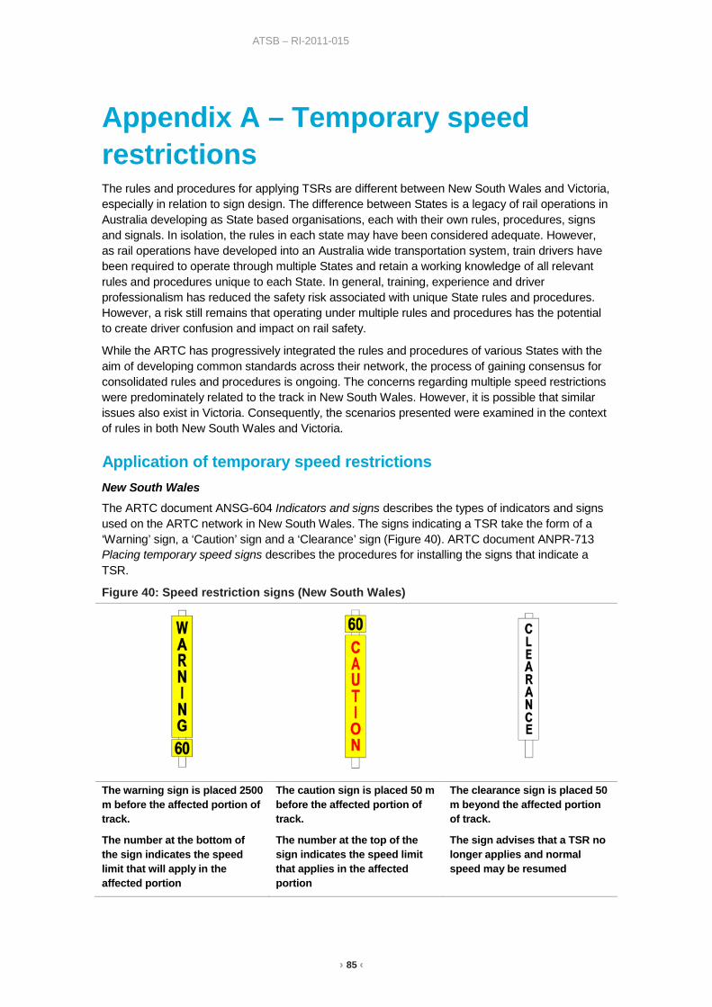
› 85 ‹
ATSB – RI-2011-015
Appendix A – Temporary speed restrictions The rules and procedures for applying TSRs are different between New South Wales and Victoria, especially in relation to sign design. The difference between States is a legacy of rail operations in Australia developing as State based organisations, each with their own rules, procedures, signs and signals. In isolation, the rules in each state may have been considered adequate. However, as rail operations have developed into an Australia wide transportation system, train drivers have been required to operate through multiple States and retain a working knowledge of all relevant rules and procedures unique to each State. In general, training, experience and driver professionalism has reduced the safety risk associated with unique State rules and procedures. However, a risk still remains that operating under multiple rules and procedures has the potential to create driver confusion and impact on rail safety.
While the ARTC has progressively integrated the rules and procedures of various States with the aim of developing common standards across their network, the process of gaining consensus for consolidated rules and procedures is ongoing. The concerns regarding multiple speed restrictions were predominately related to the track in New South Wales. However, it is possible that similar issues also exist in Victoria. Consequently, the scenarios presented were examined in the context of rules in both New South Wales and Victoria.
Application of temporary speed restrictions New South Wales
The ARTC document ANSG-604 Indicators and signs describes the types of indicators and signs used on the ARTC network in New South Wales. The signs indicating a TSR take the form of a ‘Warning’ sign, a ‘Caution’ sign and a ‘Clearance’ sign (Figure 40). ARTC document ANPR-713 Placing temporary speed signs describes the procedures for installing the signs that indicate a TSR.
Figure 40: Speed restriction signs (New South Wales)
The warning sign is placed 2500 m before the affected portion of track.
The number at the bottom of the sign indicates the speed limit that will apply in the affected portion
The caution sign is placed 50 m before the affected portion of track.
The number at the top of the sign indicates the speed limit that applies in the affected portion
The clearance sign is placed 50 m beyond the affected portion of track.
The sign advises that a TSR no longer applies and normal speed may be resumed
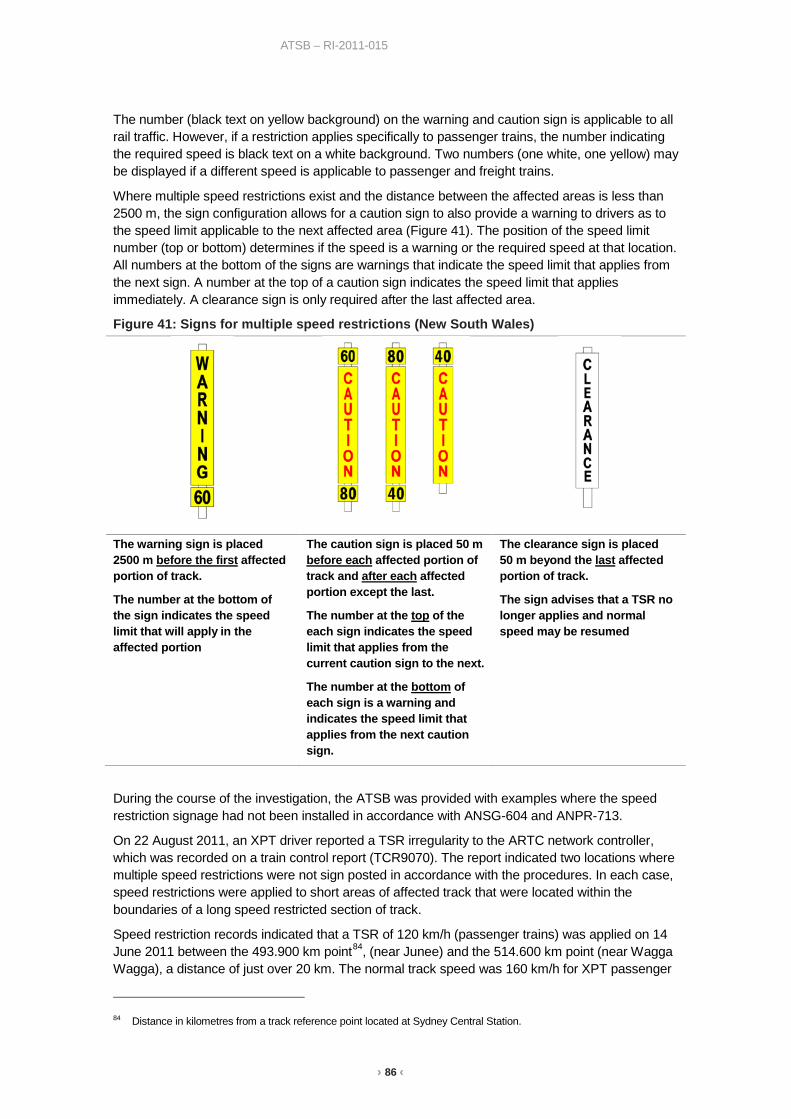
› 86 ‹
ATSB – RI-2011-015
The number (black text on yellow background) on the warning and caution sign is applicable to all rail traffic. However, if a restriction applies specifically to passenger trains, the number indicating the required speed is black text on a white background. Two numbers (one white, one yellow) may be displayed if a different speed is applicable to passenger and freight trains.
Where multiple speed restrictions exist and the distance between the affected areas is less than 2500 m, the sign configuration allows for a caution sign to also provide a warning to drivers as to the speed limit applicable to the next affected area (Figure 41). The position of the speed limit number (top or bottom) determines if the speed is a warning or the required speed at that location. All numbers at the bottom of the signs are warnings that indicate the speed limit that applies from the next sign. A number at the top of a caution sign indicates the speed limit that applies immediately. A clearance sign is only required after the last affected area.
Figure 41: Signs for multiple speed restrictions (New South Wales)
The warning sign is placed 2500 m before the first affected portion of track.
The number at the bottom of the sign indicates the speed limit that will apply in the affected portion
The caution sign is placed 50 m before each affected portion of track and after each affected portion except the last.
The number at the top of the each sign indicates the speed limit that applies from the current caution sign to the next.
The number at the bottom of each sign is a warning and indicates the speed limit that applies from the next caution sign.
The clearance sign is placed 50 m beyond the last affected portion of track.
The sign advises that a TSR no longer applies and normal speed may be resumed
During the course of the investigation, the ATSB was provided with examples where the speed restriction signage had not been installed in accordance with ANSG-604 and ANPR-713.
On 22 August 2011, an XPT driver reported a TSR irregularity to the ARTC network controller, which was recorded on a train control report (TCR9070). The report indicated two locations where multiple speed restrictions were not sign posted in accordance with the procedures. In each case, speed restrictions were applied to short areas of affected track that were located within the boundaries of a long speed restricted section of track.
Speed restriction records indicated that a TSR of 120 km/h (passenger trains) was applied on 14 June 2011 between the 493.900 km point84, (near Junee) and the 514.600 km point (near Wagga Wagga), a distance of just over 20 km. The normal track speed was 160 km/h for XPT passenger
84 Distance in kilometres from a track reference point located at Sydney Central Station.
› 87 ‹
ATSB – RI-2011-015
trains and 115 km/h for freight trains. On 4 July 2011, a second TSR of 80 km/h was applied for all trains over a short 150 m section of track between 496.850 km and 497.000 km points, which was entirely within the boundaries of the first TSR. A similar configuration was reported between the 534.900 km point, (near Uranquinty) and the 547.000 km point (near The Rock) a distance of just over 12 km. In this case, two short speed restricted areas (80 km/h and 60 km/h) were located within the boundaries of the longer speed restricted (120 km/h) section of track.
The report (TCR9070) advised that a clearance sign had been installed at the end of each TSR, including the short speed restricted sections within the longer sections. A clearance sign means a TSR no longer applies and normal track speed may be resumed. However, in this case, the first TSR (120 km/h) was intended to apply both before and after the short sections of speed restricted track.
Figure 42 shows an example of the TSR signage as installed on 22 August 2011 (upper image) and an alternative layout that is consistent with the rules and procedures (lower image)85. The figure illustrates how an additional clearance sign removes the speed restriction from a section of track that was intended to have a TSR limit of 120 km/h for passenger trains. The solution illustrated in the alternative layout returns the limit for XPT passenger trains to 120 km/h while also allowing freight trains to travel at up to 100 km/h.
85 Note that Figure 42 only illustrates the signage for rail traffic travelling in one direction.

› 88 ‹
ATSB – RI-2011-015
Figure 42: TSR signage between 493.900km and 514.600km
Source: ATSB
While the ARTC procedure (ANPR-713) does not provide a diagram to illustrate the configuration of signs to be used where a TSR is placed within the boundaries of another TSR, it does clearly state that the clearance sign is to be located 50 m after the ‘last’ speed restricted area. Based on the information provided to the ATSB, it appeared as though the second (short section) TSRs were applied without knowledge or consideration of the first (long section) TSRs.
Driver interviews identified a number of other irregularities with respect to multiple TSRs. In most cases, the issue related to a series of restrictions (often less than 2500 m apart) where a warning sign was located within the boundaries of the previous TSR. For example, Figure 42 illustrates a warning sign placed before the 80 km/h caution sign. This is not a valid configuration under the ARTC rule (ANSG-604) and procedure (ANPR-713) for TSRs.
While the signage as illustrated at Figure 42 was not a valid configuration under the rules, the placement of the 80 km/h warning sign did not present a safety risk and in fact provided additional warning for drivers of a change in speed ahead. However, the placement of the clearance sign 50 m beyond the 80 km/h restriction unintentionally released the 120 km/h restriction and therefore allowed XPT services to travel at the normal track speed of 160 km/h.
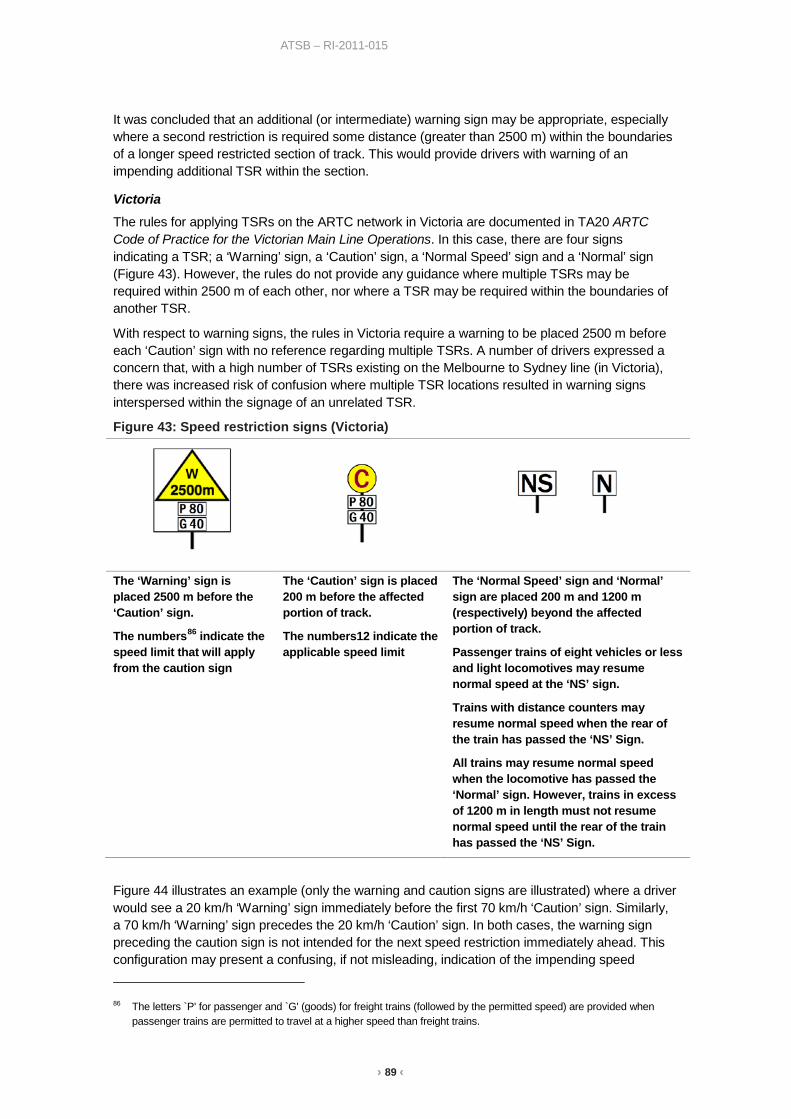
› 89 ‹
ATSB – RI-2011-015
It was concluded that an additional (or intermediate) warning sign may be appropriate, especially where a second restriction is required some distance (greater than 2500 m) within the boundaries of a longer speed restricted section of track. This would provide drivers with warning of an impending additional TSR within the section.
Victoria The rules for applying TSRs on the ARTC network in Victoria are documented in TA20 ARTC Code of Practice for the Victorian Main Line Operations. In this case, there are four signs indicating a TSR; a ‘Warning’ sign, a ‘Caution’ sign, a ‘Normal Speed’ sign and a ‘Normal’ sign (Figure 43). However, the rules do not provide any guidance where multiple TSRs may be required within 2500 m of each other, nor where a TSR may be required within the boundaries of another TSR.
With respect to warning signs, the rules in Victoria require a warning to be placed 2500 m before each ‘Caution’ sign with no reference regarding multiple TSRs. A number of drivers expressed a concern that, with a high number of TSRs existing on the Melbourne to Sydney line (in Victoria), there was increased risk of confusion where multiple TSR locations resulted in warning signs interspersed within the signage of an unrelated TSR.
Figure 43: Speed restriction signs (Victoria)
The ‘Warning’ sign is placed 2500 m before the ‘Caution’ sign.
The numbers86 indicate the speed limit that will apply from the caution sign
The ‘Caution’ sign is placed 200 m before the affected portion of track.
The numbers12 indicate the applicable speed limit
The ‘Normal Speed’ sign and ‘Normal’ sign are placed 200 m and 1200 m (respectively) beyond the affected portion of track.
Passenger trains of eight vehicles or less and light locomotives may resume normal speed at the ‘NS’ sign.
Trains with distance counters may resume normal speed when the rear of the train has passed the ‘NS’ Sign.
All trains may resume normal speed when the locomotive has passed the ‘Normal’ sign. However, trains in excess of 1200 m in length must not resume normal speed until the rear of the train has passed the ‘NS’ Sign.
Figure 44 illustrates an example (only the warning and caution signs are illustrated) where a driver would see a 20 km/h ‘Warning’ sign immediately before the first 70 km/h ‘Caution’ sign. Similarly, a 70 km/h ‘Warning’ sign precedes the 20 km/h ‘Caution’ sign. In both cases, the warning sign preceding the caution sign is not intended for the next speed restriction immediately ahead. This configuration may present a confusing, if not misleading, indication of the impending speed 86 The letters `P' for passenger and `G' (goods) for freight trains (followed by the permitted speed) are provided when
passenger trains are permitted to travel at a higher speed than freight trains.

› 90 ‹
ATSB – RI-2011-015
restriction. Unlike the New South Wales rules, there is no provision under the rules in Victoria to use a ‘Caution’ sign as a warning sign for the next restricted area. Consequently, there currently appears to be no alternative in Victoria other than provide a warning sign before each TSR.
The configuration in Figure 44 does not illustrate the ‘Normal Speed’ sign (200 m after each TSR location) and the ‘Normal’ sign (1200 m after each TSR location). Without any guidance to the contrary, it is possible that signage may be applied to affected areas without consideration of adjacent or nearby TSRs. Consequently, a ‘Normal Speed’ and/or a ‘Normal’ sign may be installed at a location whereby a restriction could be unintentionally released when a TSR was intended to remain (similar to the scenario described above in New South Wales).
Figure 44: Multiple speed restrictions (Victoria)
Source: ATSB
Operator imposed speed restrictions During interviews conducted by the ATSB, representatives from train operators and train drivers who regularly travel the line between Melbourne and Sydney raised the issue of operator imposed speed restrictions. Their statements indicated that both passenger and freight organisations and drivers were imposing additional speed restrictions due to poor track conditions and their concerns regarding the safety of train operations. Examples were provided by both Pacific National and V/Line. Pacific National periodically issued their drivers with a ‘Local Safety Notice’ which specified speed limits to apply for all Pacific National trains over the Melbourne to Sydney line, while V/Line periodically issued memos to their train drivers specifying speed limits to apply to all V/Line trains. These actions suggested the possibility that the TSRs imposed by the ARTC as part of the inspection, assessment and maintenance process were not considered adequate or safe by train operators.
At times during 2010 and 2011, the ARTC had multiple restrictions in place between Melbourne and Albury, mostly at 80 km/h, but with a few locations restricted to lower speeds. The rail organisations decided to impose speed restrictions over much more extensive distances than those imposed by the ARTC, though the speed limits were not much different (that is, generally 80 km/h). This would imply that in general, the limits imposed by the ARTC were considered appropriate where posted, but needed to cover more extensive areas of track.
The ATSB examined the evidence provided to better understand the reasoning behind the self-imposed speed restrictions. The information indicated that operators experienced extensive areas of rough riding over much of the track between Melbourne and Albury, though they acknowledged that TSRs had been applied to most areas. In addition, organisations found it near impossible for trains to run at posted track speeds because of the requirement to slow down for the multiple ARTC imposed TSRs.

› 91 ‹
ATSB – RI-2011-015
Examination of TSR records found that multiple TSRs were often applied within 5 km of each other. Considering that many freight trains are over 1.5 km long, it is evident that after clearing one restriction, trains would almost reach the next. Consequently, there is limited opportunity for trains to increase speed, and if they did, rarely could they reach maximum track speed before needing to slow in preparation for the next restriction.
Based on the evidence available to date, the operator imposed speed restrictions appeared to have been applied for a number of reasons. Organisations acknowledged that extensive areas of rough riding increased the risk of driver/passenger injury or damage to rolling-stock/freight. However, they also noted that multiple and frequent TSRs were detrimental to operational efficiency and on-time running.
Considering the operator imposed restrictions were no slower than the ARTC imposed TSRs, it was apparent organisations considered the ARTC restrictions appropriate. However, it was also evident that organisations had experienced conditions that prompted them to conduct their own testing and/or inspections into ride quality over the Melbourne to Sydney track. As a result of these tests, organisations applied their own blanket restrictions over long sections of track which addressed both operational efficiency and improved ride quality over track not subjected to TSRs.
From the ARTC perspective, the opportunity exists to consider the practical consequences on rail operations when applying frequent TSRs.
› 92 ‹
ATSB – RI-2011-015
Sources and submissions Sources of information The ATSB gathered information from key railway organisations such as the ARTC, V/Line, RailCorp (CountryLink) and Pacific National. In addition, information was obtained from rail safety regulators and independent investigation agencies in New South Wales and Victoria.
The ATSB conducted interviews with train drivers who regularly travel the rail line between Melbourne and Sydney and have talked with representatives from railway unions. Investigators also travelled on the track geometry car observing and talking to technicians while they were measuring the track geometry between Melbourne and Goulburn.
References Accell Pty Ltd – North East Corridor, Patullus Lane, Albury, 2009
Accell Pty Ltd – Ballast Remediation, Main South & North East Corridor – Somerton to Macarthur 2010
ARTC document – ARTC (Track & Civil) Code of Practice
ARTC document – ARTC Engineering (Track & Civil) Code of Practice - Section 5, Track Geometry
ARTC document ETD-02-03 – Concrete Sleepers (Heavy Duty), Design
ARTC document EDS-32-01 – Signalling rolling stock interface, table GW40
ARTC document ETH-10-01 – Mud Hole Management guideline
ARTC document ESC-04-01 – Signal sighting and position
ARTC document TA02 – Network interface co-ordination plan
ARTC document ANSG – 604 Indicators and signs
ARTC document ANPR – 713 Placing temporary speed signs
AR001-AT-MAW-OP-002 – Re-sleeper Side Insertion Methodology
AS/NZS ISO 8402:1994 – Quality management and quality assurance – Vocabulary
AS 2758.7-1996 – Aggregates and rock for engineering purposes - Railway ballast.
ATSB Interim Factual Report RO-2011-015 – Investigation of the safety of rail operations on the interstate rail line between Melbourne and Sydney – published in February 2012
ATSB report RO-2008-009 – Derailment of Train 5WX2 near Winton, Victoria, 31 July 2008
ATSB report RO-2009-009 – Reported signal irregularity at Cootamundra NSW involving trains ST22 and 4MB7
ATSB report RO-2010-015 – Derailment of train 1MP5 at Goddards, WA, 28 December 2010
ATSB report RO-2011-007 – Parting of train 9827 near Gunning, NSW on 30 March 2011
ATSB report RO-2011-012 – Rolling stock irregularity on XPT train ST24 near Coolaroo Victoria on 11 August 2011
ATSB report RO-2012-008 – Train parting near Seymour VIC on 1 August 2012
Australian Government – Department of Infrastructure and Transport, National Alliance Contracting Guidelines, Guidance Note 3 – Key Risk Areas and Trade-Offs
Cantrell Rail Service – Independent assessment of the rail line between Melbourne-Sydney, 2011

› 93 ‹
ATSB – RI-2011-015
Chief Investigator, Transport Safety report 2011/08 – Safeworking Irregularity and Near-Miss Incident between Seymour and Avenel 24 Jul 2011
CSIRO – Australian Soil Classification
Institution of Railway Signal Engineers (IRSE), April 2001, Report 3 – The Influence of Human Factors on the performance of Railway Systems, and IRSE signalling philosophy review, report of working group 2
Mashour – Human Factors in Signalling Systems (1974)
Occurrence Notification – Standard One (ON-S1) – Guideline for the Reporting of Notifiable Occurrences – June 2008
Occurrence Classification – Guideline One (OC-G1) – Guideline for the Top Event Classification of Notifiable Occurrences – June 2008
OTSI Rail Safety Investigation Report – Steel Sleeper Introduction on NSW Class 1 Main Line Track 1996-2004
Rail Industry Safety and Standards Board (RISSB) – Australian Standard Rail Networks Code of Practice – Volume 4 – Track, Civil and Electrical Infrastructure - Part 1: Infrastructure Management
Rail Industry Safety and Standards Board (RISSB) – Code of Practice-Volume 4, Track and Civil Infrastructure
Rail Industry Safety and Standards Board (RISSB) – National Guideline Glossary of Railway Terminology
Rail Safety and Standards Board (RSSB, UK) – Guidance Note GE/GN8537, Guidance on Signal Positioning and Visibility
Railways of Australia (ROA) – A Review of Track Design Procedures, Volume 2, Sleepers and Ballast’ 1991
SIA-PPR-GL-CON-051 – South Improvement Alliance, Process Procedure, Concrete resleepering, Side insertion method
Wilkinson, A., Haque, A., Kodikara, J., Adamson, J., Christie, D. – Improvement of Problematic Soils by Lime Slurry Pressure Injection: Case Study, 2010
Submissions Under Part 4, Division 2 (Investigation Reports), Section 26 of the Transport Safety Investigation Act 2003, the ATSB may provide a draft report, on a confidential basis, to any person whom the ATSB considers appropriate. Section 26 (1) (a) of the Act allows a person receiving a draft report to make submissions to the ATSB about the draft report.
A draft of this report was provided to the ARTC, Asciano, V/Line, Aurizon, RailCorp, Downer EDI Works, John Holland, Unions, the Independent Transport Safety Regulator (New South Wales), Public Transport Safety Victoria, the Office of Transport Safety Investigations (New South Wales), the Chief Investigator Transport Safety (Victoria) and a number of individuals.
Submissions were received from the ARTC, the Independent Transport Safety Regulator (New South Wales), Public Transport Safety Victoria, Chief Investigator Transport Safety (Victoria), John Holland and one individual. The submissions were reviewed and where considered appropriate, the text of the report was amended accordingly.
› 94 ‹
ATSB – RI-2011-015
Australian Transport Safety Bureau The Australian Transport Safety Bureau (ATSB) is an independent Commonwealth Government statutory agency. The ATSB is governed by a Commission and is entirely separate from transport regulators, policy makers and service providers. The ATSB’s function is to improve safety and public confidence in the aviation, marine and rail modes of transport through excellence in: independent investigation of transport accidents and other safety occurrences; safety data recording, analysis and research; fostering safety awareness, knowledge and action.
The ATSB is responsible for investigating accidents and other transport safety matters involving civil aviation, marine and rail operations in Australia that fall within Commonwealth jurisdiction, as well as participating in overseas investigations involving Australian registered aircraft and ships. A primary concern is the safety of commercial transport, with particular regard to fare-paying passenger operations.
The ATSB performs its functions in accordance with the provisions of the Transport Safety Investigation Act 2003 and Regulations and, where applicable, relevant international agreements.
Purpose of safety investigations The object of a safety investigation is to identify and reduce safety-related risk. ATSB investigations determine and communicate the factors related to the transport safety matter being investigated.
It is not a function of the ATSB to apportion blame or determine liability. At the same time, an investigation report must include factual material of sufficient weight to support the analysis and findings. At all times the ATSB endeavours to balance the use of material that could imply adverse comment with the need to properly explain what happened, and why, in a fair and unbiased manner.
Developing safety action Central to the ATSB’s investigation of transport safety matters is the early identification of safety issues in the transport environment. The ATSB prefers to encourage the relevant organisation(s) to initiate proactive safety action that addresses safety issues. Nevertheless, the ATSB may use its power to make a formal safety recommendation either during or at the end of an investigation, depending on the level of risk associated with a safety issue and the extent of corrective action undertaken by the relevant organisation.
When safety recommendations are issued, they focus on clearly describing the safety issue of concern, rather than providing instructions or opinions on a preferred method of corrective action. As with equivalent overseas organisations, the ATSB has no power to enforce the implementation of its recommendations. It is a matter for the body to which an ATSB recommendation is directed to assess the costs and benefits of any particular means of addressing a safety issue.
When the ATSB issues a safety recommendation to a person, organisation or agency, they must provide a written response within 90 days. That response must indicate whether they accept the recommendation, any reasons for not accepting part or all of the recommendation, and details of any proposed safety action to give effect to the recommendation.
The ATSB can also issue safety advisory notices suggesting that an organisation or an industry sector consider a safety issue and take action where it believes it appropriate. There is no requirement for a formal response to an advisory notice, although the ATSB will publish any response it receives.


AT
SB
Transp
ort S
afety Rep
ort
Rail S
afety Issue Investigation
Safety of rail operations on the interstate rail line betw
een M
elbourne and Sydney
RI-2011-015
Final – 22 August 2013
Investigatio
n
Australian Transport Safety Bureau
24 Hours 1800 020 616 Web www.atsb.gov.auTwitter @ATSBinfoEmail [email protected]