Safety Locking Devices - · PDF fileL200 Safety Locking Devices Original operating...
32
L200 Safety Locking Devices Original operating instructions EN 2013/10 - 607320 We reserve the right to make technical changes Phone: 800.894.0412 - Fax: 888.723.4773 - Web: www.clrwtr.com - Email: [email protected]
Transcript of Safety Locking Devices - · PDF fileL200 Safety Locking Devices Original operating...
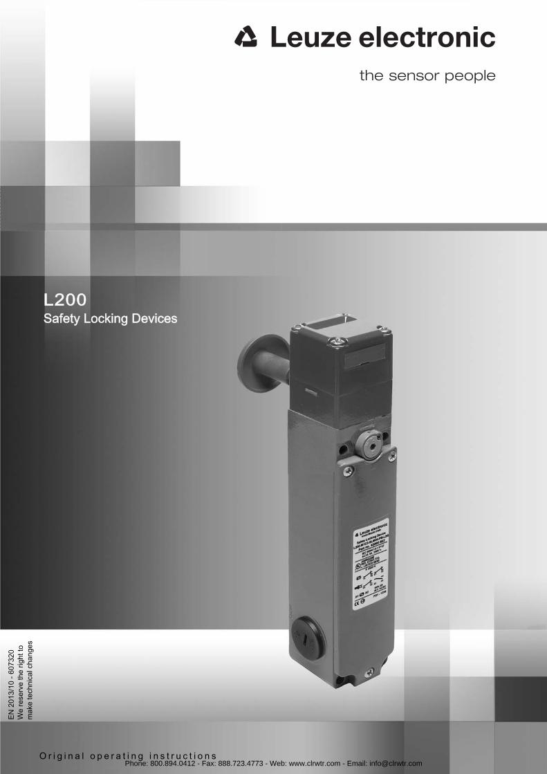
L200Safety Locking Devices
O r i g i n a l o p e r a t i n g i n s t r u c t i o n s
EN 2
013/
10 -
6073
20W
e re
serv
e th
e rig
ht to
m
ake
tech
nica
l cha
nges
Phone: 800.894.0412 - Fax: 888.723.4773 - Web: www.clrwtr.com - Email: [email protected]

Leuze electronic L200 3
1 About this document. . . . . . . . . . . . . . . . . . . . . . . . . . . . . . . . . . . . . . . . . . . . . . . . . . . . 41.1 Other applicable documents . . . . . . . . . . . . . . . . . . . . . . . . . . . . . . . . . . . . . . . . . . . . . . . . . . . . . . . 41.2 Used symbols and signal words . . . . . . . . . . . . . . . . . . . . . . . . . . . . . . . . . . . . . . . . . . . . . . . . . . . . 4
2 Safety . . . . . . . . . . . . . . . . . . . . . . . . . . . . . . . . . . . . . . . . . . . . . . . . . . . . . . . . . . . . . . . 52.1 Approved purpose and foreseeable improper operation . . . . . . . . . . . . . . . . . . . . . . . . . . . . . . . . . . 52.1.1 Proper use . . . . . . . . . . . . . . . . . . . . . . . . . . . . . . . . . . . . . . . . . . . . . . . . . . . . . . . . . . . . . . . . . . . . . 52.1.2 Foreseeable misuse . . . . . . . . . . . . . . . . . . . . . . . . . . . . . . . . . . . . . . . . . . . . . . . . . . . . . . . . . . . . . 62.2 Competent personnel . . . . . . . . . . . . . . . . . . . . . . . . . . . . . . . . . . . . . . . . . . . . . . . . . . . . . . . . . . . . 62.3 Responsibility for safety. . . . . . . . . . . . . . . . . . . . . . . . . . . . . . . . . . . . . . . . . . . . . . . . . . . . . . . . . . . 72.4 Disclaimer . . . . . . . . . . . . . . . . . . . . . . . . . . . . . . . . . . . . . . . . . . . . . . . . . . . . . . . . . . . . . . . . . . . . . 7
3 Device description . . . . . . . . . . . . . . . . . . . . . . . . . . . . . . . . . . . . . . . . . . . . . . . . . . . . . 8
4 Functions . . . . . . . . . . . . . . . . . . . . . . . . . . . . . . . . . . . . . . . . . . . . . . . . . . . . . . . . . . . 104.1 Spring locking . . . . . . . . . . . . . . . . . . . . . . . . . . . . . . . . . . . . . . . . . . . . . . . . . . . . . . . . . . . . . . . . . 104.2 Electromagnetic locking. . . . . . . . . . . . . . . . . . . . . . . . . . . . . . . . . . . . . . . . . . . . . . . . . . . . . . . . . . 104.3 Emergency release button. . . . . . . . . . . . . . . . . . . . . . . . . . . . . . . . . . . . . . . . . . . . . . . . . . . . . . . . 104.4 LED display . . . . . . . . . . . . . . . . . . . . . . . . . . . . . . . . . . . . . . . . . . . . . . . . . . . . . . . . . . . . . . . . . . . 10
5 Applications . . . . . . . . . . . . . . . . . . . . . . . . . . . . . . . . . . . . . . . . . . . . . . . . . . . . . . . . . 11
6 Mounting. . . . . . . . . . . . . . . . . . . . . . . . . . . . . . . . . . . . . . . . . . . . . . . . . . . . . . . . . . . . 126.1 Adjusting the deflection head. . . . . . . . . . . . . . . . . . . . . . . . . . . . . . . . . . . . . . . . . . . . . . . . . . . . . . 126.2 Mounting the safety locking device . . . . . . . . . . . . . . . . . . . . . . . . . . . . . . . . . . . . . . . . . . . . . . . . . 126.3 Mounting the actuator . . . . . . . . . . . . . . . . . . . . . . . . . . . . . . . . . . . . . . . . . . . . . . . . . . . . . . . . . . . 13
7 Electrical connection . . . . . . . . . . . . . . . . . . . . . . . . . . . . . . . . . . . . . . . . . . . . . . . . . . 157.1 Connecting the contact block. . . . . . . . . . . . . . . . . . . . . . . . . . . . . . . . . . . . . . . . . . . . . . . . . . . . . . 15
8 Starting up the device. . . . . . . . . . . . . . . . . . . . . . . . . . . . . . . . . . . . . . . . . . . . . . . . . . 17
9 Testing . . . . . . . . . . . . . . . . . . . . . . . . . . . . . . . . . . . . . . . . . . . . . . . . . . . . . . . . . . . . . 189.1 To be performed prior to the initial start-up by competent personnel . . . . . . . . . . . . . . . . . . . . . . . 189.2 To be performed periodically by competent personnel . . . . . . . . . . . . . . . . . . . . . . . . . . . . . . . . . . 189.3 To be performed daily by the operating personnel . . . . . . . . . . . . . . . . . . . . . . . . . . . . . . . . . . . . . 18
10 Cleaning . . . . . . . . . . . . . . . . . . . . . . . . . . . . . . . . . . . . . . . . . . . . . . . . . . . . . . . . . . . . 20
11 Disposing . . . . . . . . . . . . . . . . . . . . . . . . . . . . . . . . . . . . . . . . . . . . . . . . . . . . . . . . . . . 21
12 Service and support . . . . . . . . . . . . . . . . . . . . . . . . . . . . . . . . . . . . . . . . . . . . . . . . . . . 22
13 Technical data . . . . . . . . . . . . . . . . . . . . . . . . . . . . . . . . . . . . . . . . . . . . . . . . . . . . . . . 2313.1 Dimensions . . . . . . . . . . . . . . . . . . . . . . . . . . . . . . . . . . . . . . . . . . . . . . . . . . . . . . . . . . . . . . . . . . . 25
14 Ordering information and accessories . . . . . . . . . . . . . . . . . . . . . . . . . . . . . . . . . . . . . 3014.1 Accessories . . . . . . . . . . . . . . . . . . . . . . . . . . . . . . . . . . . . . . . . . . . . . . . . . . . . . . . . . . . . . . . . . . . 3014.1.1Dimensional drawings: accessories. . . . . . . . . . . . . . . . . . . . . . . . . . . . . . . . . . . . . . . . . . . . . . . . . 31
15 EC Declaration of Conformity. . . . . . . . . . . . . . . . . . . . . . . . . . . . . . . . . . . . . . . . . . . . 33
Phone: 800.894.0412 - Fax: 888.723.4773 - Web: www.clrwtr.com - Email: [email protected]
About this document
Leuze electronic L200 4
1 About this document
1.1 Other applicable documentsThe information on the L200 safety locking device is divided into two documents. Document “L200 Application information” contains only the most important safety notices. For the safe implementation, testing and operation, download document “L200 Safe implementation
and operation” from Leuze website or request it from tel. +49 8141 5350-111.
Table 1.1: Documents for the L200 safety locking device
1.2 Used symbols and signal words
Table 1.2: Warning symbols and signal words
Table 1.3: Other symbols
Purpose and target group Title Source
Detailed information for all users L200 Safe implementation and operation (this document)
On the Internet, download from: Leuze website.
Basic information for technicians and operating company
L200 Application information Print document part no. 607246 included in the delivery contents of the product
Symbol for dangers
NOTICE Signal word for property damageIndicates dangers that may result in property damage if the measures for danger avoid-ance are not followed.
CAUTION Signal word for minor injuryIndicates dangers that may result in minor injury if the measures for danger avoidance are not followed.
WARNING Signal word for serious injuryIndicates dangers that may result in severe or fatal injury if the measures for danger avoid-ance are not followed.
DANGER Signal word for life-threatening dangerIndicates dangers that will result in severe or fatal injury if the measures for danger avoid-ance are not followed.
Symbol for tipsText passages with this symbol provide you with further information.
Symbols for action stepsText passages with this symbol instruct you to perform actions.
xxx Placeholder in the product description for all variants
Phone: 800.894.0412 - Fax: 888.723.4773 - Web: www.clrwtr.com - Email: [email protected]
Safety
Leuze electronic L200 5
2 SafetyBefore using the safety locking device, a risk evaluation must be performed according to valid standards (e.g. EN ISO 12100, EN ISO 13849-1). For mounting, operating and testing, document “L200 Safe imple- mentation and operation”, application information as well as all applicable national and international stan- dards, regulations, rules and directives must be observed. Observe and print out relevant and supplied documents and distribute to the affected personnel.
The following standards apply for the risk evaluation at the protective device prior to using the safety locking device:
• EN ISO 12100, Safety of machinery, risk assessment• EN ISO 13849-1, Safety-related parts of control systems
The realizable category of the integration in control circuits according to EN ISO 13849-1 is dependent on the used contact block and wiring.In particular, the following national and international legal regulations apply for the start-up, technical inspections and work with safety locking devices:
• Machinery directive 2006/42/EC• Low voltage directive 2006/95/EC• Electromagnetic compatibility 2004/108/EC• Use of work equipment directive 2009/104/EG• Safety regulations• Accident-prevention regulations and safety rules• Industrial safety regulation and employment protection act• Product Safety Act
2.1 Approved purpose and foreseeable improper operation
2.1.1 Proper use
• The safety locking device must only be used after it has been selected in accordance with therespectively applicable instructions and relevant standards, rules and regulations regarding laborprotection and safety at work, and after it has been installed on the machine, connected, commis-sioned, and checked by a competent person.
• When selecting the safety locking device it must be ensured that its safety-related capability meetsor exceeds the required performance level PLr ascertained in the risk assessment.
• It must be in perfect condition and inspected regularly.• The switching process must only be triggered by an actuator approved for this safety locking device
that is connected to the moveable guard in a non-detachable and tamperproof manner.
L200 safety locking devices must be connected in such a way that a dangerous state can only be activated while the protective device is closed and so that they prevent premature opening during the lag time before
WARNINGSerious accidents may result if the voltage supply is interrupted!If the voltage supply to the electromagnet of an electromagnetically locked safety locking device is inter- rupted, the protective device may be opened immediately.
For safety-related information you may also contact the local authorities (e.g., industrial inspec- torate, employer's liability insurance association, labor inspectorate, occupational safety and health authority).
WARNINGA running machine can cause severe injuries!Make certain that, during all conversions, maintenance work and inspections, the system is securely
shut down and protected against being restarted.
Phone: 800.894.0412 - Fax: 888.723.4773 - Web: www.clrwtr.com - Email: [email protected]

Safety
Leuze electronic L200 6
the dangerous state has ended. Electromagnetic safety locking devices may only be used instead of spring-locked safety locking devices in exceptional cases and following appropriate risk evaluation.Connection conditions:
• dangerous state can be activated only with closed protective device and locked locking device• protective device cannot be opened while locking device is locked• upon actuation of the emergency release button, the protective device can be opened immediately in
the event of an emergency, even while the machine is running (this triggers a stop signal)The emergency release button must only be accessible to operating personnel from within the closed protective device.
Furthermore, the L200 safety locking device must not be used under the following conditions:• high concentration of dust particles in the surrounding area• rapidly changing ambient temperature (leads to condensation)• in the event of strong physical shocks• in explosive or easily flammable atmospheres• the mounting locations are not sufficiently stable• in the event of electromagnetic interference• the safety of multiple persons is dependent on the function of this safety locking device (e.g. nuclear
power plants, trains, aircraft, motor vehicles, incinerators, medical devices)Handling the safety locking device: Never unlock the safety locking device before the dangerous state has ended (Exception: Actuation of
the emergency release button). Observe the permissible environmental conditions for storage and operation (see chapter 13 „Technical
data“). Immediately replace damaged safety locking devices according to these instructions. Use cable gland, insulation materials and connecting wires of the appropriate protection rating. Protect the safety locking device from penetrating foreign bodies (e.g. shavings, sand and blasting
agent). Before performing painting work, cover the actuation slot, actuator and name plate. Immediately clean any contamination from the safety locking device that impacts function according to
these instructions.Make no structural changes to the safety locking device. The safety locking device must be exchanged after a maximum of 20 years.
2.1.2 Foreseeable misuseAny use other than that defined under the "approved purpose" or which goes beyond that use of the safety locking device is considered improper use!E.g. using without non-detachably mounted actuator
• looping into the safety circuit parts that are not relevant to safety• using the locking device as a limit stop
2.2 Competent personnel
Prerequisites for competent personnel:• suitable technical training• knows the rules and regulations for labor protection, safety at work and safety technology and can
assess the safety of the machine• knows the instructions for the safety locking device and the machine• was instructed by the responsible individuals on the mounting and operation of the machine and of
the safety locking device
Phone: 800.894.0412 - Fax: 888.723.4773 - Web: www.clrwtr.com - Email: [email protected]
Safety
Leuze electronic L200 7
2.3 Responsibility for safetyManufacturer and operating company must ensure that the machine and implemented safety locking device function properly and that all affected persons are adequately informed and trained.The type and content of all imparted information must not lead to unsafe actions by users.
The manufacturer of the machine is responsible for: • safe machine construction• safe implementation of the safety locking device• imparting all relevant information to the operating company• adhering to all regulations and directives for the safe starting-up of the machine
The operating company is responsible for:• instructing the operating personnel• maintaining the safe operation of the machine• adhering to all regulations and directives for labor protection and safety at work• regular testing by competent personnel
2.4 DisclaimerLeuze electronic GmbH + Co. KG is not liable in the following cases:
• Safety locking device is not used as intended• Safety notices are not adhered to• mounting and electrical connection are not properly performed• Reasonably foreseeable misuse is not taken into account
Phone: 800.894.0412 - Fax: 888.723.4773 - Web: www.clrwtr.com - Email: [email protected]

Device description
Leuze electronic L200 8
3 Device descriptionThe safety locking device of the L200 series is an electro-mechanical switching device in a metal housing for heavy-duty applications satisfying protection rating IP 67. By means of the funnel-shaped insertion opening, the actuator self-centers, even if the door is slightly misadjusted. Two LEDs indicate the activa- tion state of the magnet. The safety locking device is also available in versions with auxiliary release and emergency release button (see table 14.1). In the latter case, various extensions (accessories) enable optimal adaptation to the special requirements of local conditions.
1 Deflection head2 Dust cover3 Insertion opening for actuator4 Auxiliary release (L200-M1C3-SLM24-L2G, L200-M1C3-SLM24-PB-L2G and L200-M0C3-SLM24-
L2G)5 Control LEDs6 Housing cover7 Name plate (connection data, production code and year of manufacture)8 Emergency release button (L200-M1C3-SLM24-PB-L2G)
The actuation directions of the deflection head and emergency release button can be adjusted in 90° incre- ments. By means of 5 possible approach directions and a selection of different actuators, the safety locking device can be mounted in any position.
Figure 3.1: Approach directions
3
12
5
6
7
8
4
Phone: 800.894.0412 - Fax: 888.723.4773 - Web: www.clrwtr.com - Email: [email protected]
Device description
Leuze electronic L200 9
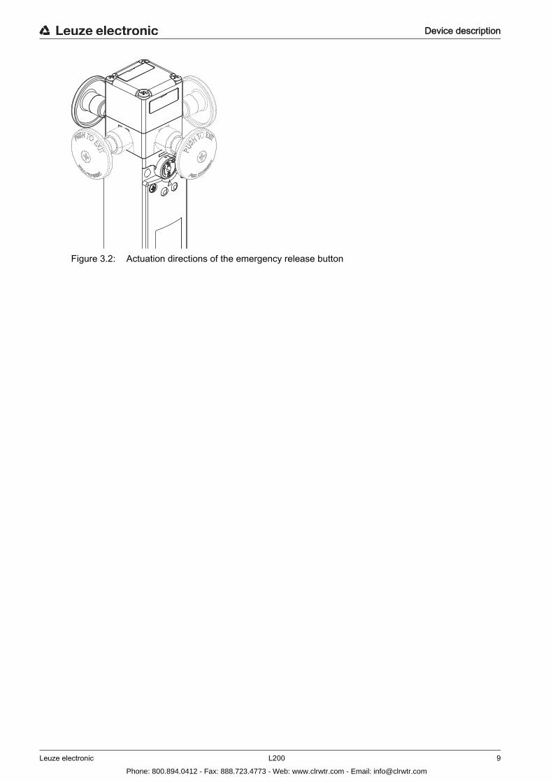
Figure 3.2: Actuation directions of the emergency release button
Phone: 800.894.0412 - Fax: 888.723.4773 - Web: www.clrwtr.com - Email: [email protected]
Functions
Leuze electronic L200 10
4 Functions
4.1 Spring lockingWith the L200-M1C3-SLM24-L2G, L200-M1C3-SLM24-PB-L2G and L200-M0C3-SLM24-L2G the safety contacts close when the actuator moves in, and the actuator is mechanically held in the locked position by the spring force. The dangerous process can be activated via the safety relay. After the dangerous process has stopped, the operating voltage for unlocking the electromagnet is applied and the actuator is released. The protective device can be opened. In the event of failure of the operating voltage, release is also possible via the auxiliary release.
4.2 Electromagnetic lockingWith the L200-M1C3-MLM24-L2G, the safety contact for the position monitoring of the protective device closes when the actuator is moved in. The electromagnet is energized and holds the actuator in the locked position. The dangerous process can be activated via the safety relay.On release, the voltage supply to the electromagnet is interrupted. The electromagnet releases the actu- ator and the protective device can be opened.
4.3 Emergency release buttonWith the L200-M1C3-SLM24-PB-L2G, the protective device can be opened immediately following actua- tion of the emergency release button, even while the machine is running (in addition, a stop command is triggered).
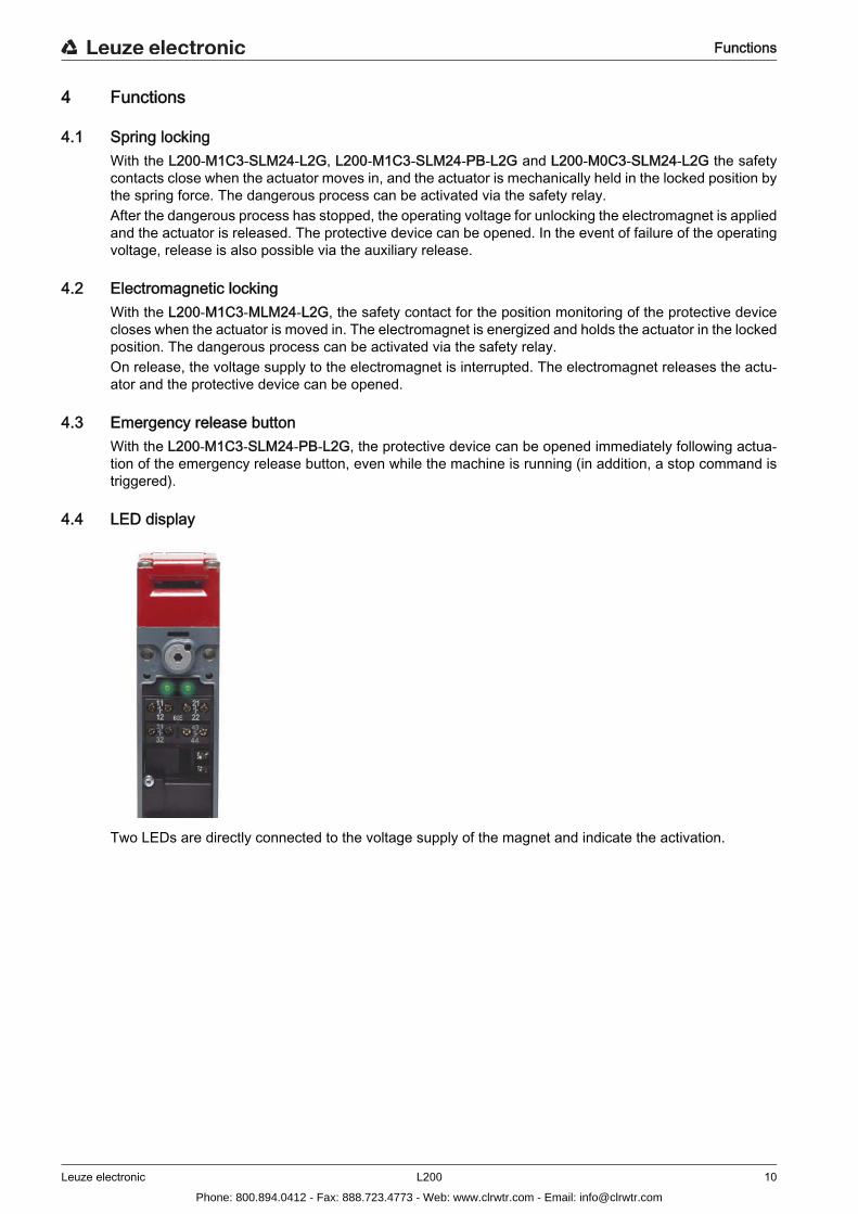
4.4 LED display
Two LEDs are directly connected to the voltage supply of the magnet and indicate the activation.
Phone: 800.894.0412 - Fax: 888.723.4773 - Web: www.clrwtr.com - Email: [email protected]
Applications
Leuze electronic L200 11
5 ApplicationsL200 safety locking devices with spring locking are suitable for e.g. position monitoring and locking the following protective devices:
• turning or swiveling moveable guards• laterally moveable protective gratings or sliding gates• heavy, moveable guards or sliding gates• confusing or unclear danger zones (emergency release button)
Safety locking devices with electromagnetic lock are used primarily as locks for moveable guards to prevent undesired process interruptions.
Phone: 800.894.0412 - Fax: 888.723.4773 - Web: www.clrwtr.com - Email: [email protected]

Mounting
Leuze electronic L200 12
6 Mounting
6.1 Adjusting the deflection head Unscrew the 4 screws on the deflection head. Turn the deflection head (and, if applicable, the emergency release button) in the desired direction.
Tighten the 4 screws on the deflection head with 0.8–1.2 Nm. Close unused opening with the dust cover.
6.2 Mounting the safety locking device
Prerequisites for mounting:• deflection head is set (and, if applicable, emergency release button)• fully assembled
Select the mounting location so that the following conditions are satisfied:
• Safety locking device and actuator can be well matched to one another and permanently mounted• accessible to qualified personnel for testing and replacement• auxiliary release is accessible to qualified personnel• emergency release button is only accessible to operating personnel from within the closed protective
device
WARNINGSevere accidents may result if the safety locking device is not mounted properly!The protective function of the safety locking device is only ensured if used in the intended area of appli- cation and if it is mounted professionally.Mounting may only be performed by competent personnel. Observe standards, regulations and these instructions. Protect the housing and deflection head from materials penetrating the enclosure (environmental con-
ditions see chapter 13 „Technical data“). Test to ensure proper function.
Phone: 800.894.0412 - Fax: 888.723.4773 - Web: www.clrwtr.com - Email: [email protected]
Mounting
Leuze electronic L200 13
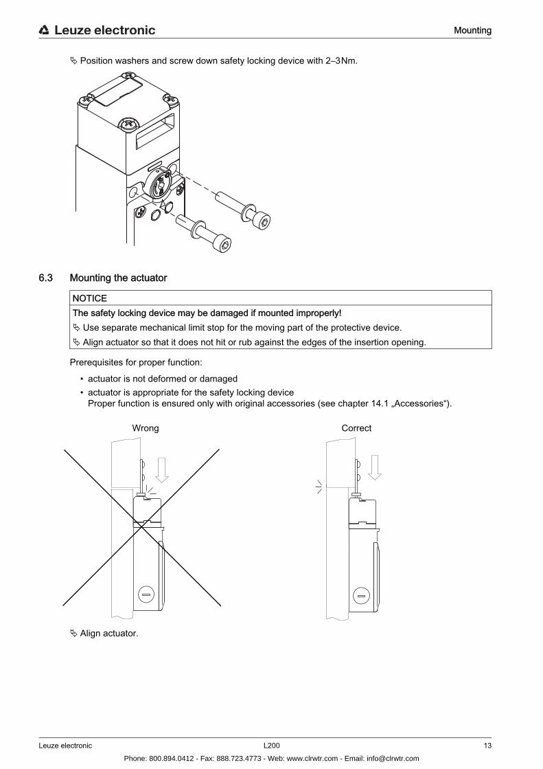
Position washers and screw down safety locking device with 2–3 Nm.
6.3 Mounting the actuator
Prerequisites for proper function:
• actuator is not deformed or damaged• actuator is appropriate for the safety locking device
Proper function is ensured only with original accessories (see chapter 14.1 „Accessories“).
Align actuator.
NOTICEThe safety locking device may be damaged if mounted improperly! Use separate mechanical limit stop for the moving part of the protective device. Align actuator so that it does not hit or rub against the edges of the insertion opening.
Wrong Correct
Phone: 800.894.0412 - Fax: 888.723.4773 - Web: www.clrwtr.com - Email: [email protected]
Mounting
Leuze electronic L200 14
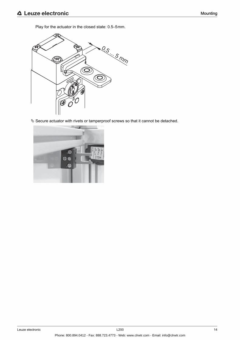
Play for the actuator in the closed state: 0.5–5 mm.
Secure actuator with rivets or tamperproof screws so that it cannot be detached.
0,5 ... 5 mm
Phone: 800.894.0412 - Fax: 888.723.4773 - Web: www.clrwtr.com - Email: [email protected]
Electrical connection
Leuze electronic L200 15
7 Electrical connection
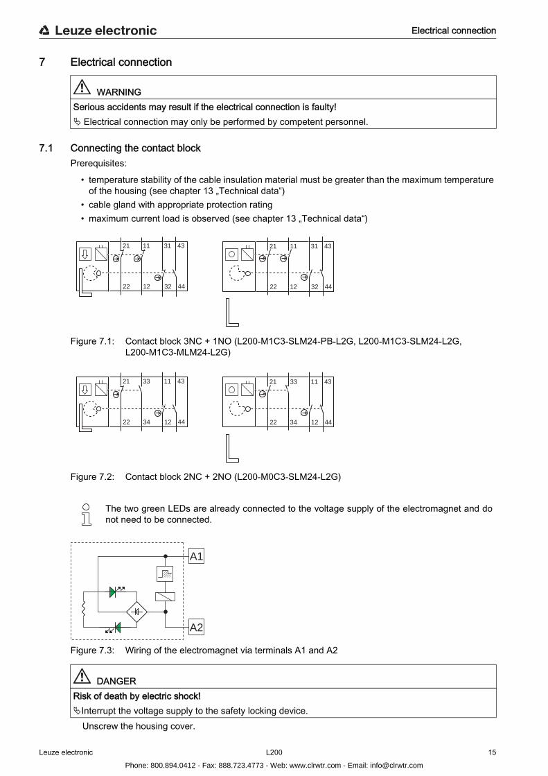
7.1 Connecting the contact blockPrerequisites:
• temperature stability of the cable insulation material must be greater than the maximum temperatureof the housing (see chapter 13 „Technical data“)
• cable gland with appropriate protection rating• maximum current load is observed (see chapter 13 „Technical data“)
Figure 7.1: Contact block 3NC + 1NO (L200-M1C3-SLM24-PB-L2G, L200-M1C3-SLM24-L2G, L200-M1C3-MLM24-L2G)
Figure 7.2: Contact block 2NC + 2NO (L200-M0C3-SLM24-L2G)
Figure 7.3: Wiring of the electromagnet via terminals A1 and A2
WARNINGSerious accidents may result if the electrical connection is faulty! Electrical connection may only be performed by competent personnel.
The two green LEDs are already connected to the voltage supply of the electromagnet and do not need to be connected.
DANGERRisk of death by electric shock!Interrupt the voltage supply to the safety locking device.
Unscrew the housing cover.
12
11
22
21
32
31
44
43
12
11
22
21
32
31
44
43
34
33
22
21
12
11
44
43
34
33
22
21
12
11
44
43
A1
A2
Phone: 800.894.0412 - Fax: 888.723.4773 - Web: www.clrwtr.com - Email: [email protected]

Electrical connection
Leuze electronic L200 16
Connect the contact block according to the application-specific circuit diagram.
* Spark extinction circuit, suitable spark extinction providedFigure 7.4: Connection example L200-M1C3-SLM24-L2G
Tighten cable terminal screws with 0.6–0.8 Nm.
Tighten the housing cover with 0.8–1.2 Nm.
L200-M1C3-SLM24-L2G
11 12 21 22-A1 3231
0VPE PE
0V
Var. B
Var. A
MSI-SR4B
-K3
-A2
-K4-K4
-K3 x1
x2
L-
13 23 41S22 S12 S31 S33 S34 S35 33
+24
V
2 A
OP
D-
1 A
OP
D+
2 A
OP
D+
IV-0
RE
S-0
RE
S-I
1
2
L+
-K3
-K4
14 24 42
0V
34
1
2
1
2
L+ L+
A1
A2-K3
L- L-
*
A1
A2-K4
*
1
2
+24V +24V
4443
1 2
-S1
Phone: 800.894.0412 - Fax: 888.723.4773 - Web: www.clrwtr.com - Email: [email protected]

Starting up the device
Leuze electronic L200 17
8 Starting up the device
Prerequisites:
• safety locking device is mounted and connected according to these instructions• operating personnel have been trained in the correct use
Test the function of the safety locking device (see chapter 9 „Testing“).The safety locking device is then ready for use.
WARNINGSevere accidents may result if the safety locking device is not used properly! Before unlocking the safety locking device and opening the protective device, wait until the dangerous
state has ended (exception in emergencies: emergency release button).
Phone: 800.894.0412 - Fax: 888.723.4773 - Web: www.clrwtr.com - Email: [email protected]
Testing
Leuze electronic L200 18
9 TestingL200 safety locking devices are maintenance-free. Always replace the entire safety locking device including actuator. For the testing intervals, observe nationally applicable regulations. Document all tests in a comprehensible manner.
9.1 To be performed prior to the initial start-up by competent personnel Check whether the safety locking device is operated according to its specified environmental conditions
(see chapter 13 „Technical data“). Test to ensure proper mechanical and electrical function (see chapter 9.2 „To be performed periodically
by competent personnel“).
9.2 To be performed periodically by competent personnelMechanical function Stop the dangerous state and open the protective device. Check that the components are securely fastened. Test the cable entry for leaks. Check safety locking device and actuator for damage, deposits, deformation and wear. If present, test auxiliary release. If present, test emergency release button. Test several times whether the actuator can be easily moved into the safety locking device.
Electrical function
Stop the dangerous state and open the protective device.Make certain that the machine cannot be started while the protective device is open. Close the protective device and start the machine.Make certain that the protective device cannot be opened until after the machine has been shut down
and the safety locking device has been released.Make certain that the dangerous state ends before the protective device can be opened.
If present, test whether actuation of the emergency release button immediately releases the actuator and stops the machine.
9.3 To be performed daily by the operating personnel
Stop the dangerous state and open the protective device.Check the safety locking device and actuator for damage or tampering.
Make certain that the machine cannot be started while the protective device is open.
WARNINGSevere accidents may result if tests are not performed properly!Make certain that there are no persons in the danger zone.
DANGERRisk of life-threatening injury while the machine is running! Do not remain in the danger zone while testing the emergency release button.
WARNINGSevere accidents may result if tests are not performed properly!Make certain that there are no persons in the danger zone.
Phone: 800.894.0412 - Fax: 888.723.4773 - Web: www.clrwtr.com - Email: [email protected]

Testing
Leuze electronic L200 19
Close the protective device and start the machine.Make certain that the protective device cannot be opened until after the machine has been switched off
and the safety locking device has been released.
Phone: 800.894.0412 - Fax: 888.723.4773 - Web: www.clrwtr.com - Email: [email protected]
Cleaning
Leuze electronic L200 20
10 CleaningThere must be no soiling (e.g. shavings or dust) present, especially in the deflection head of the safety locking device.Prerequisites for cleaning:
• protective device is opened and machine is switched off• voltage supply for the safety locking device is interrupted
Periodically clean the safety locking device while the protective device is opened (e.g. with vacuum cleaner).
Phone: 800.894.0412 - Fax: 888.723.4773 - Web: www.clrwtr.com - Email: [email protected]
Disposing
Leuze electronic L200 21
11 Disposing For disposal observe the applicable national regulations regarding electronic components.
Phone: 800.894.0412 - Fax: 888.723.4773 - Web: www.clrwtr.com - Email: [email protected]
Service and support
Leuze electronic L200 22
12 Service and support
Telephone number for 24-hour standby service:+49 (0) 7021 573-0
Service hotline: +49 (0) 8141 5350-111Monday to Thursday, 8.00 a.m. to 5.00 p.m. (UTC+1)Friday, 8.00 a.m. to 4.00 p.m. (UTC +1)
Return address for repairs:Service CenterLeuze electronic GmbH + Co. KGIn der Braike 1D-73277 Owen / Germany
Phone: 800.894.0412 - Fax: 888.723.4773 - Web: www.clrwtr.com - Email: [email protected]

Technical data
Leuze electronic L200 23
13 Technical data
Table 13.1: General
Table 13.2: Safety
Switch type Interlock device with guard interlocking according to EN 1088
Actuator, external AC-AHLxx series: straight, angled, resilient, align-able
Lock type L200-M1C3-SLM24-L2G: spring forceL200-M0C3-SLM24-L2G: spring forceL200-M1C3-SLM24-PB-L2G: spring forceL200-M1C3-MLM24-L2G: electromagnetic
Lock actuation L200-M1C3-SLM24-L2G: springL200-M0C3-SLM24-L2G: springL200-M1C3-SLM24-PB-L2G: springL200-M1C3-MLM24-L2G: electromagnet
Approach actuation directions 1 x above, 4 x lateral (90 °)
Approach speed min. 1 mm/s, max. 0.5 m/s
Actuation force (pull-out) 30 N
Mechanical life time in accordance with IEC 60947-5-1
1 x 10⁶ switching cycles
Actuation frequency according to IEC 60947-5-1 max. 600 per hour
Service life (TM) in accordance with EN ISO 13849-1
20 years
Number of cycles before dangerous failure (B10d) according to EN 61810-2
5,000,000
Usage category according to EN 60947-5-1
Maximum load when using 5-pin cables:Maximum load when using 8-pin cables:
AC 15 (Ue / Ie):250 V / 5 A
DC 13 (Ue / Ie):24 V / 6 A125 V / 1.1 A250 V / 0.4 A
24 V / 4 A (see chapter 14.1 „Accessories“)
24 V / 2 A (see chapter 14.1 „Accessories“)
Dimensions (dimensional drawings) see chapter 13.1 „Dimensions“
Protection class IP 67
Contact protection grounding
Recoil tolerance 4.5 mm
Interlocking force max. 2500 N
Phone: 800.894.0412 - Fax: 888.723.4773 - Web: www.clrwtr.com - Email: [email protected]

Technical data
Leuze electronic L200 24
Table 13.3: Housing
Table 13.4: Connection
Table 13.5: Environment
Contact allocation magnet: 2NCactuator: 1NC + 1NO(L200-M1C3-SLM24-L2G, L200-M1C3-SLM24-PB-L2G, L200-M1C3-MLM24-L2G)
magnet: 1NC + 1NOactuator: 1NC + 1NO(L200-M0C3-SLM24-L2G)
Contact material silver alloy
Switching principle slow-action contact
Contact opening force-fit
Rated insulation voltage 250 V AC, 300 V DC
Conventional thermal current max. 10 A
Short-circuit protection according to IEC 60269-1 magnet: 0.5 A, 24 V, type gGsafety circuit: 10 A, 500 V, type gG
Magnet operating voltage and tolerance 24 V DC (–10 % … +25 %)
Switch-on time 100 %
Power consumption average, 9 VA
Housing material metal
Number of cable entries 3
Type of cable entry M20 x 1.5
Conductor cross-section (stranded) 1 x 0.34 mm2 … 2 x 1.5 mm2
Temperature range, operation –25 ... +60 °C
Dirt level, external,according to EN 60947-1
3
These tables do not apply in combination with additional M12 plug or connecting cable except where these components are explicitly mentioned.
Phone: 800.894.0412 - Fax: 888.723.4773 - Web: www.clrwtr.com - Email: [email protected]

Technical data
Leuze electronic L200 25
13.1 Dimensions
Figure 13.1: Dimensions of L200-M1C3-SLM24-L2G in mm
33.2
144
45.2
5.4
302.440.22.4
5.519
4.740
12.3
18.346
40
38.8
24
Phone: 800.894.0412 - Fax: 888.723.4773 - Web: www.clrwtr.com - Email: [email protected]
Technical data
Leuze electronic L200 26
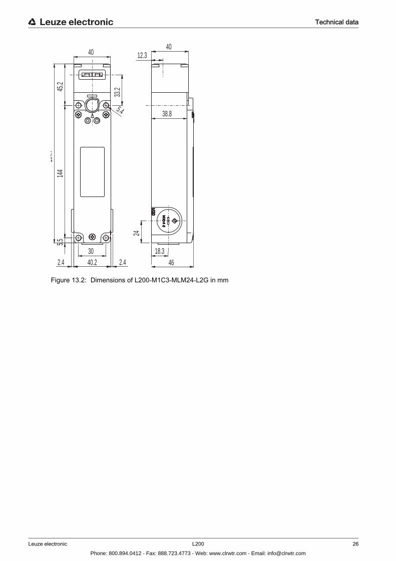
Figure 13.2: Dimensions of L200-M1C3-MLM24-L2G in mm
33.2
40
5.4
302.4 40.2 2.4
5.514
445
.219
4.712.3
18.346
24
38.8
40
Phone: 800.894.0412 - Fax: 888.723.4773 - Web: www.clrwtr.com - Email: [email protected]

Technical data
Leuze electronic L200 27
Figure 13.3: Dimensions of L200-M1C3-SLM24-PB-L2G in mm
53.465
.414
45.5 30
40
5.4
40.22.4 2.4
214.9
18.3
24
12.3
5.5 9.515 15
46
40
Ø 17
Ø38
38.837.7
Phone: 800.894.0412 - Fax: 888.723.4773 - Web: www.clrwtr.com - Email: [email protected]
Technical data
Leuze electronic L200 28
Figure 13.4: Dimensions of L200-M1C3-SLM24-PB-L2G in mm
Figure 13.5: Dimensions of AC-PB40-L200 in mm
18.3
24
5.5 9.2
46
Ø38
Ø17
30 max
14.7
44.7
5.5 12.2
Ø38
Ø17
40 MAX
17.7
Phone: 800.894.0412 - Fax: 888.723.4773 - Web: www.clrwtr.com - Email: [email protected]

Technical data
Leuze electronic L200 29
Figure 13.6: Dimensions of AC-PB60-L200 in mm
Figure 13.7: Dimensions of AC-PB500-L200 in mm
Ø17
5.5 12.2Ø
38
60 MAX
17.7
5.5
Ø17
500 MAX60 MIN
25 MAX10 MIN
Ø38
Phone: 800.894.0412 - Fax: 888.723.4773 - Web: www.clrwtr.com - Email: [email protected]
Ordering information and accessories
Leuze electronic L200 30
14 Ordering information and accessories
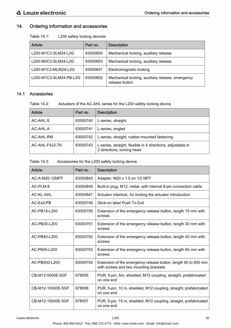
Table 14.1: L200 safety locking devices
14.1 Accessories
Table 14.2: Actuators of the AC-AHL series for the L200 safety locking device
Table 14.3: Accessories for the L200 safety locking device
Article Part no. Description
L200-M1C3-SLM24-L2G 63000650 Mechanical locking, auxiliary release
L200-M0C3-SLM24-L2G 63000653 Mechanical locking, auxiliary release
L200-M1C3-MLM24-L2G 63000651 Electromagnetic locking
L200-M1C3-SLM24-PB-L2G 63000652 Mechanical locking, auxiliary release, emergency release button
Article Part no. Description
AC-AHL-S 63000740 L-series, straight
AC-AHL-A 63000741 L-series, angled
AC-AHL-RM 63000742 L-series, straight, rubber-mounted fastening
AC-AHL-F4J2-TK 63000743 L-series, straight, flexible in 4 directions, adjustable in 2 directions, turning head
Article Part no. Description
AC-A-M20-12NPT 63000843 Adapter, M20 x 1.5 on 1/2 NPT
AC-PLM-8 63000845 Built-in plug, M12, metal, with internal 8-pin connection cable
AC-KL-AHL 63000847 Actuator interlock, for locking the actuator introduction
AC-Exit-PB 63000749 Stick-on label Push To Exit
AC-PB15-L200 63000750 Extension of the emergency release button, length 15 mm with screws
AC-PB30-L200 63000751 Extension of the emergency release button, length 30 mm with screws
AC-PB40-L200 63000752 Extension of the emergency release button, length 40 mm with screws
AC-P605-L200 63000753 Extension of the emergency release button, length 60 mm with screws
AC-PB500-L200 63000754 Extension of the emergency release button, length 60 to 500 mm with screws and two mounting brackets
CB-M12-5000E-5GF 678055 PUR, 5-pin, 5m, shielded, M12 coupling, straight, prefabricated on one end
CB-M12-10000E-5GF 678056 PUR, 5-pin, 10 m, shielded, M12 coupling, straight, prefabricated on one end
CB-M12-15000E-5GF 678057 PUR, 5-pin, 15 m, shielded, M12 coupling, straight, prefabricated on one end
Phone: 800.894.0412 - Fax: 888.723.4773 - Web: www.clrwtr.com - Email: [email protected]
Ordering information and accessories
Leuze electronic L200 31
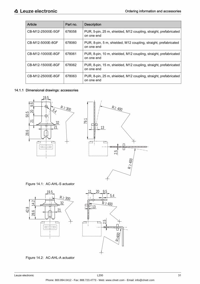
14.1.1 Dimensional drawings: accessories
Figure 14.1: AC-AHL-S actuator
Figure 14.2: AC-AHL-A actuator
CB-M12-25000E-5GF 678058 PUR, 5-pin, 25 m, shielded, M12 coupling, straight, prefabricated on one end
CB-M12-5000E-8GF 678060 PUR, 8-pin, 5 m, shielded, M12 coupling, straight, prefabricated on one end
CB-M12-10000E-8GF 678061 PUR, 8-pin, 10 m, shielded, M12 coupling, straight, prefabricated on one end
CB-M12-15000E-8GF 678062 PUR, 8-pin, 15 m, shielded, M12 coupling, straight, prefabricated on one end
CB-M12-25000E-8GF 678063 PUR, 8-pin, 25 m, shielded, M12 coupling, straight, prefabricated on one end
Article Part no. Description
R 300
19.5
9.5
2021
50.5
28.6
5.4
3221
≥
R
400
R 400
13
79.1
2.5
≥
≥
R 30032
21
19.5
14.2
28.642
.8
≥R 400
R 4
00
2.5
13
9.520115.4
≥
≥
Phone: 800.894.0412 - Fax: 888.723.4773 - Web: www.clrwtr.com - Email: [email protected]
Ordering information and accessories
Leuze electronic L200 32
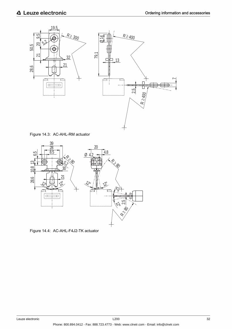
Figure 14.3: AC-AHL-RM actuator
Figure 14.4: AC-AHL-F4J2-TK actuator
R 300
19,5
9,5
2021
50,5
28,6
32
21
5,2≥ R 400
R
400
Ø14
13
79,1
2,5
7
≥
≥
12°1
1310
.828
.66.5
2°21
2839
8.5
80≥
5.20
R
3
12°
4.8Ø 4.2
20
1
12°
R80
2°
.5≥
R80
≥
2
12°
Phone: 800.894.0412 - Fax: 888.723.4773 - Web: www.clrwtr.com - Email: [email protected]
EC Declaration of Conformity
Leuze electronic L200 33
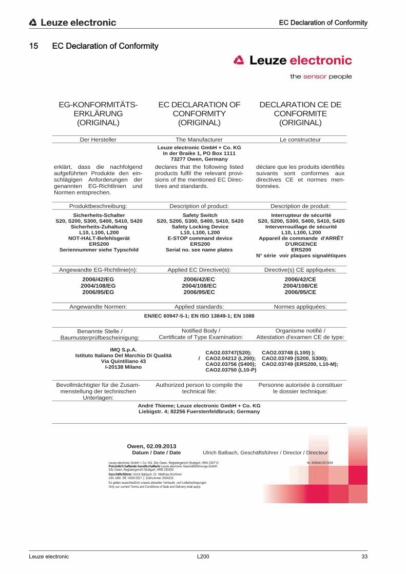
15 EC Declaration of Conformity
Leuze electronic GmbH + Co. KG, Sitz Owen, Registergericht Stuttgart, HRA 230712 Persönlich haftende Gesellschafterin Leuze electronic Geschäftsführungs-GmbH, Sitz Owen, Registergericht Stuttgart, HRB 230550 Geschäftsführer: Ulrich Balbach, Dr. Matthias Kirchherr USt.-IdNr. DE 145912521 │ Zollnummer 2554232 Es gelten ausschließlich unsere aktuellen Verkaufs- und Lieferbedingungen Only our current Terms and Conditions of Sale and Delivery shall apply
Nr. 609340-2013/09
EG-KONFORMITÄTS-ERKLÄRUNG(ORIGINAL)
EC DECLARATION OF CONFORMITY
(ORIGINAL)
DECLARATION CE DE CONFORMITE
(ORIGINAL)
Der Hersteller The Manufacturer Le constructeur Leuze electronic GmbH + Co. KG
In der Braike 1, PO Box 1111 73277 Owen, Germany
erklärt, dass die nachfolgend aufgeführten Produkte den ein-schlägigen Anforderungen der genannten EG-Richtlinien und Normen entsprechen.
declares that the following listed products fulfil the relevant provi-sions of the mentioned EC Direc-tives and standards.
déclare que les produits identifiés suivants sont conformes aux directives CE et normes men-tionnées.
Produktbeschreibung: Description of product: Description de produit:
Sicherheits-Schalter S20, S200, S300, S400, S410, S420
Sicherheits-Zuhaltung L10, L100, L200
NOT-HALT-Befehlsgerät ERS200
Seriennummer siehe Typschild
Safety SwitchS20, S200, S300, S400, S410, S420
Safety Locking Device L10, L100, L200
E-STOP command device ERS200
Serial no. see name plates
Interrupteur de sécuritéS20, S200, S300, S400, S410, S420
Interverrouillage de sécurité L10, L100, L200
Appareil de commande d'ARRÊT D'URGENCE
ERS200N° série voir plaques signalétiques
Angewandte EG-Richtlinie(n): Applied EC Directive(s): Directive(s) CE appliquées:
2006/42/EG 2006/42/EC 2006/42/CE2004/108/EG 2004/108/EC 2004/108/CE2006/95/EG 2006/95/EC 2006/95/CE
Angewandte Normen: Applied standards: Normes appliquées:
EN/IEC 60947-5-1; EN ISO 13849-1; EN 1088
Benannte Stelle / Baumusterprüfbescheinigung:
Notified Body / Certificate of Type Examination:
Organisme notifié / Attestation d'examen CE de type:
IMQ S.p.A. Istituto Italiano Del Marchio Di Qualitá
Via Quintiliano 43 I-20138 Milano
/CAO2.03747(S20); CAO2.03748 (L100) ); CAO2.04212 (L200); CAO2.03749 (S200, S300); CAO2.03756 (S400); CAO2.03749 (ERS200, L10-M); CAO2.03750 (L10-P)
Bevollmächtigter für die Zusam-menstellung der technischen
Unterlagen:
Authorized person to compile the technical file:
Personne autorisée à constituer le dossier technique:
André Thieme; Leuze electronic GmbH + Co. KG Liebigstr. 4; 82256 Fuerstenfeldbruck; Germany
Owen, 02.09.2013 Datum / Date / Date Ulrich Balbach, Geschäftsführer / Director / Directeur
Phone: 800.894.0412 - Fax: 888.723.4773 - Web: www.clrwtr.com - Email: [email protected]