Safety Lifecycle Workbook for the Process Industry Sector
62
SAFETY LIFECYCLE WORKBOOK FOR THE PROCESS INDUSTRY SECTOR
Transcript of Safety Lifecycle Workbook for the Process Industry Sector
SAFETY LIFECYCLE WORKBOOKFOR THE PROCESS INDUSTRY SECTOR
SAFETY LIFECYCLE WORKBOOKFOR THE PROCESS INDUSTRY SECTOR
The information and any recommendations that may be provided herein are not intended for any direct or specific application and are presented as being informative in nature. As such, Emerson Process Management assumes no responsibility and disclaims all liability of any kind, however arising, as a result of using the information contained herein. Any equipment and all equipment configurations that might be referenced or selected by the authors are provided as an example only. No representation, expressed or implied, is made with regard to the availability of any equipment, process, formula, or other procedures contained herein.
The authors thank the International Electrotechnical Commission (IEC) for permission to reproduce information from its International Publication IEC 61511-1 ed.1.0 (2003).All such extracts are copyright of IEC, Geneva, Switzerland. All rights reserved. Further information on the IEC is availablefrom www.iec.ch. IEC has no responsibility for the placement and context in which the extracts and contents are reproducedby the authors, nor is IEC in any way responsible for the other content or accuracy therein.
SAFETY LIFECYCLE WORKBOOK
NoticeThe contents of this publication are presented for informational purposes only, and while every effort has been made to ensure their accuracy, theyare not to be construed as warranties or guarantees, express or implied, regarding the products or services described herein or their use orapplicability. All sales are governed by our software licensing agreement and terms and conditions, which are available upon request. We reservethe right to modify or improve the designs or specifications of our product and services at any time without notice.
First Edition © 2010 Emerson Process Management.
All rights reserved.
The Emerson logo is a trademark and service mark of Emerson Electric Co.
For Emerson Process Management trademarks and service marks, go to www.emersonprocess.com/home/news/resources/marks.pdf. All other marks arethe property of their respective owners.
Form W-00002 / Printed in USA / 500 AQ / 5-10
We invite you to share your thoughts and practical knowledge about SIS for the benefit of others in the industry.Join our DeltaV SIS Process Safety System LinkedIn group at:
http://www.linkedin.com/groups?home=&gid=2309437&trk=anet_ug_hm
If you would like to learn more about Emerson’s process safety system, please visit our website atwww.DeltaVSIS.com.
SAFETY LIFECYCLE WORKBOOKFOR THE PROCESS INDUSTRY SECTOR

SAFETY LIFECYCLE WORKBOOK
SAFETY LIFECYCLE WORKBOOK
This page intentionally left blank
SAFETY LIFECYCLE WORKBOOK i
TABLE OF CONTENTS
Introduction 1
Business ChallengesIndustry business drivers in a competitive market today 3
Safety BasicsImportant safety concepts 5International Safety Standards 5Process Hazard Analysis (PHA) 5Layers of Protection 6Safety Integration Level (SIL) 6Safety Instrumented System (SIS) 8Safety Instrumented Function (SIF) 8How do SIFs and SILs relate to each other? 8
Industry StandardsOverview of safety industry standards in the process industry 9IEC 61508–SIS Hardware/Software Design Guidance 9IEC 61508–SIS Hardware/Software Design Validation 10IEC 61511–SIS Design Guidance for the Process Industry Sector 11ANSI/ISA-84.00.01-2004 SIS for the Process Industry Sector 12
SIS ArchitectureReview of disparate and integrated control and safety system architectures 15Separation and Diversity 15Stand Alone Safety Instrumented Systems 16Integrated Control and Safety Instrumented (ICSS) 16
Safety LifecycleDescription of each phase of the safety lifecycle with example checklists and best practices 19Safety Lifecycle Overview 20Safety Management System 22SMS Considerations 23Verification 24Hazard Risk Assessment 26
SAFETY LIFECYCLE WORKBOOK
FOR THE PROCESS INDUSTRY SECTOR
TABLE OF CONTENTS
SAFETY LIFECYCLE WORKBOOK ii
Safety Lifecycle continuedHazard Risk Assessment Methods 27Allocation of Safety Functions to the Protection Layers 28SIS Assignment 29Safety Requirements Specification for the SIS 32Design and Engineering of SIS 34Installation, Commissioning and Validation 38Operation and Maintenance 40Online Testing 41Proof Testing 42Documentation 43Modification 44Decommissioning 46Management of Change 47Security 48
Supplier QualificationConsiderations when evaluating your suppliers 49Expectations 49Product and Service Certification 49
GlossaryDefinition of commonly used terms 51
Safety is Mandatory
Of all of the issues facing today’s process manufacturers, ensuring safe operations andguaranteeing shutdown when necessary are paramount. Companies that do not plan andmanage process operational risks face fines, production outages, equipment damage and seriousinjury or loss of life.
Conversely, the unwanted consequences of any part of the safety system failing safely asdesigned, but resulting in nuisance trips, drive an equally important consideration in theapplication of industrial safety systems.
For that reason, process manufacturers must ensure that design of the SIS is at the heart of aneffective safety lifecycle methodology that will enable proper process design and implementationto meet the requirements for both safety and process availability.
With today’s technology and best practices, there is no reason not to put safety first. Processmanufacturers should be familiar with key international safety standards and concepts toeffectively implement safer operations. It is important that process manufacturers work withsuppliers that have SIS sensors, logic solvers, and final control elements that meet IEC 61508standards to enable compliance with IEC 61511 / ISA84 best practices.
SAFETY LIFECYCLE WORKBOOK 1
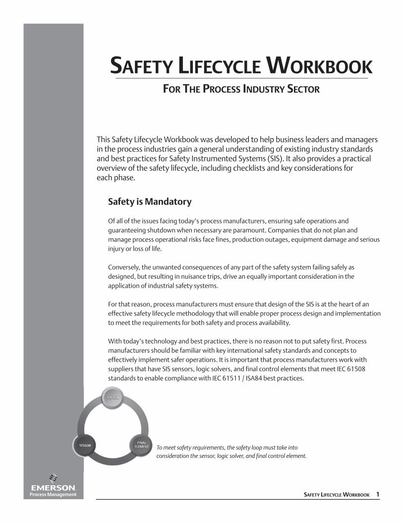
This Safety Lifecycle Workbook was developed to help business leaders and managersin the process industries gain a general understanding of existing industry standardsand best practices for Safety Instrumented Systems (SIS). It also provides a practicaloverview of the safety lifecycle, including checklists and key considerations for each phase.
To meet safety requirements, the safety loop must take into consideration the sensor, logic solver, and final control element.
SAFETY LIFECYCLE WORKBOOKFOR THE PROCESS INDUSTRY SECTOR
SAFETY LIFECYCLE WORKBOOK
SAFETY LIFECYCLE WORKBOOK
This page intentionally left blank.
BUSINESS CHALLENGES
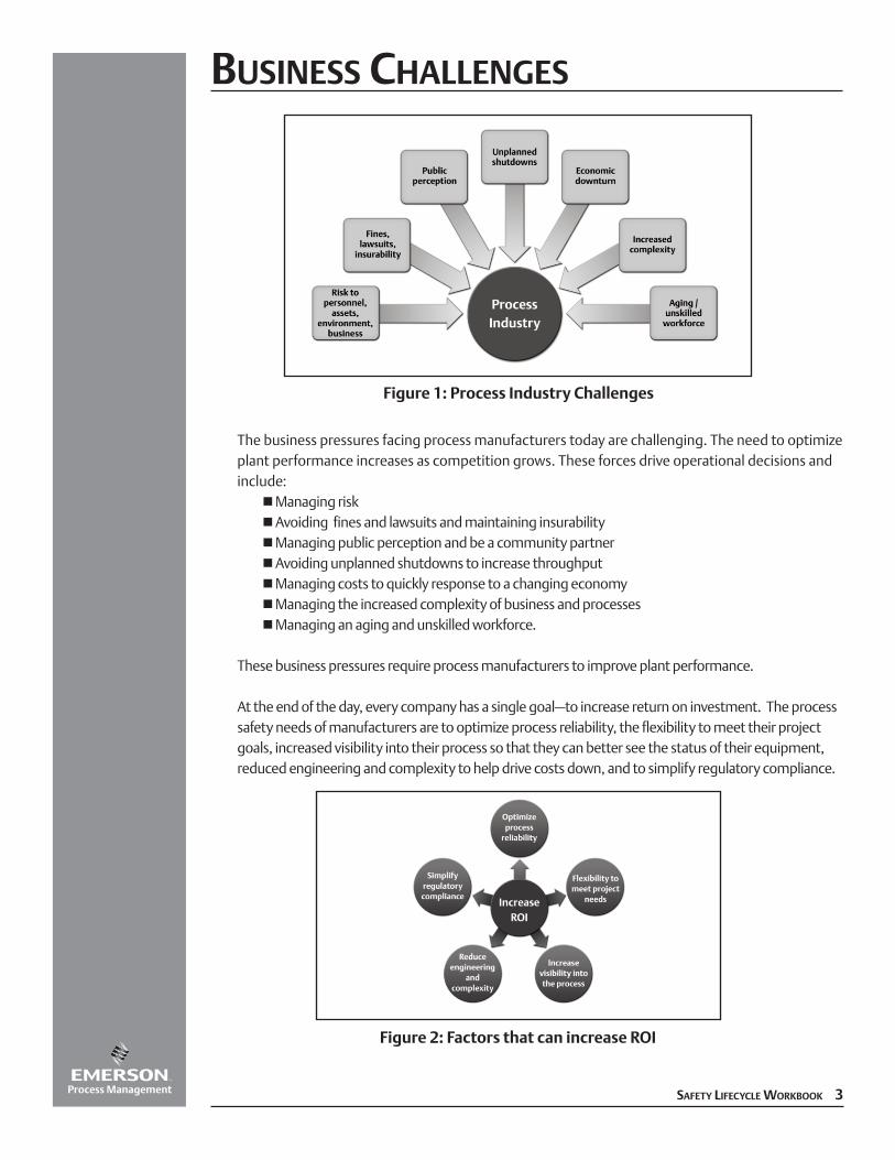
The business pressures facing process manufacturers today are challenging. The need to optimizeplant performance increases as competition grows. These forces drive operational decisions andinclude:
nManaging risknAvoiding fines and lawsuits and maintaining insurabilitynManaging public perception and be a community partnernAvoiding unplanned shutdowns to increase throughputnManaging costs to quickly response to a changing economynManaging the increased complexity of business and processesnManaging an aging and unskilled workforce.
These business pressures require process manufacturers to improve plant performance.
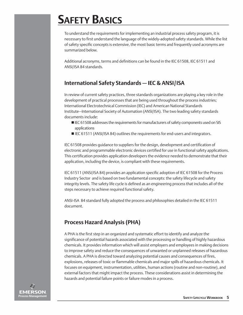
At the end of the day, every company has a single goal–to increase return on investment. The processsafety needs of manufacturers are to optimize process reliability, the flexibility to meet their projectgoals, increased visibility into their process so that they can better see the status of their equipment,reduced engineering and complexity to help drive costs down, and to simplify regulatory compliance.
SAFETY LIFECYCLE WORKBOOK 3
Figure 1: Process Industry Challenges
Figure 2: Factors that can increase ROI

BUSINESS CHALLENGES
4 SAFETY LIFECYCLE WORKBOOK
This page intentionally left blank.
SAFETY BASICSTo understand the requirements for implementing an industrial process safety program, it isnecessary to first understand the language of the widely-adopted safety standards. While the listof safety specific concepts is extensive, the most basic terms and frequently used acronyms aresummarized below.
Additional acronyms, terms and definitions can be found in the IEC 61508, IEC 61511 andANSI/ISA 84 standards.
International Safety Standards – IEC & ANSI/ISA
In review of current safety practices, three standards organizations are playing a key role in thedevelopment of practical processes that are being used throughout the process industries;International Electrotechnical Commission (IEC) and American National StandardsInstitute–International Society of Automation (ANSI/ISA). The two leading safety standardsdocuments include:
n IEC 61508 addresses the requirements for manufacturers of safety components used on SIS applications
n IEC 61511 (ANSI/ISA 84) outlines the requirements for end-users and integrators.
IEC 61508 provides guidance to suppliers for the design, development and certification ofelectronic and programmable electronic devices certified for use in functional safety applications.This certification provides application developers the evidence needed to demonstrate that theirapplication, including the device, is compliant with these requirements.
IEC 61511 (ANSI/ISA 84) provides an application specific adoption of IEC 61508 for the ProcessIndustry Sector and is based on two fundamental concepts: the safety lifecycle and safetyintegrity levels. The safety life cycle is defined as an engineering process that includes all of thesteps necessary to achieve required functional safety.
ANSI-ISA 84 standard fully adopted the process and philosophies detailed in the IEC 61511document.
Process Hazard Analysis (PHA)
A PHA is the first step in an organized and systematic effort to identify and analyze thesignificance of potential hazards associated with the processing or handling of highly hazardouschemicals. It provides information which will assist employers and employees in making decisionsto improve safety and reduce the consequences of unwanted or unplanned releases of hazardouschemicals. A PHA is directed toward analyzing potential causes and consequences of fires,explosions, releases of toxic or flammable chemicals and major spills of hazardous chemicals. Itfocuses on equipment, instrumentation, utilities, human actions (routine and non-routine), andexternal factors that might impact the process. These considerations assist in determining thehazards and potential failure points or failure modes in a process.
SAFETY LIFECYCLE WORKBOOK 5
Several methods of analysis can be used, including:n Hazard Operability (HAZOP) Studyn What If? / Checklistn Failure Mode Effect Analysis (FMEA)n Fault Tree Analysisn Event Tree Analysisn Layers of Protection Analysis
Layers of Protection
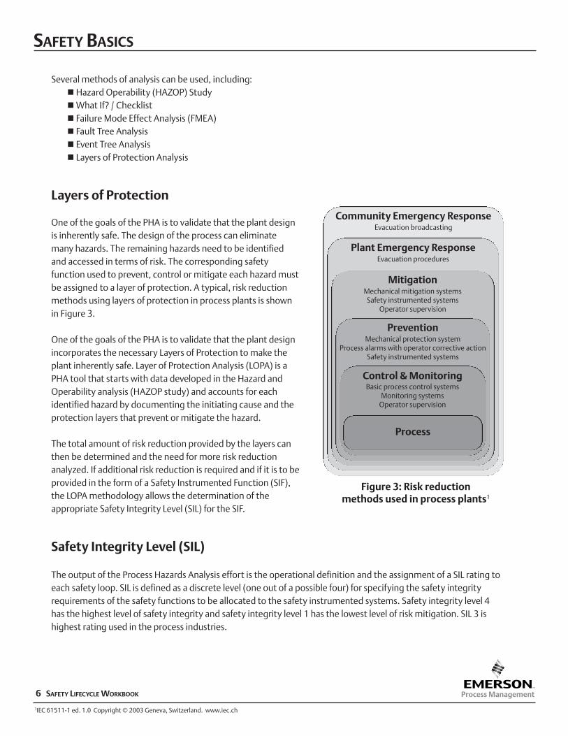
One of the goals of the PHA is to validate that the plant designis inherently safe. The design of the process can eliminatemany hazards. The remaining hazards need to be identifiedand accessed in terms of risk. The corresponding safetyfunction used to prevent, control or mitigate each hazard mustbe assigned to a layer of protection. A typical, risk reductionmethods using layers of protection in process plants is shownin Figure 3.
One of the goals of the PHA is to validate that the plant designincorporates the necessary Layers of Protection to make theplant inherently safe. Layer of Protection Analysis (LOPA) is aPHA tool that starts with data developed in the Hazard andOperability analysis (HAZOP study) and accounts for eachidentified hazard by documenting the initiating cause and theprotection layers that prevent or mitigate the hazard.
The total amount of risk reduction provided by the layers canthen be determined and the need for more risk reductionanalyzed. If additional risk reduction is required and if it is to beprovided in the form of a Safety Instrumented Function (SIF),the LOPA methodology allows the determination of theappropriate Safety Integrity Level (SIL) for the SIF.
Safety Integrity Level (SIL)
The output of the Process Hazards Analysis effort is the operational definition and the assignment of a SIL rating toeach safety loop. SIL is defined as a discrete level (one out of a possible four) for specifying the safety integrityrequirements of the safety functions to be allocated to the safety instrumented systems. Safety integrity level 4has the highest level of safety integrity and safety integrity level 1 has the lowest level of risk mitigation. SIL 3 ishighest rating used in the process industries.
SAFETY BASICS
6 SAFETY LIFECYCLE WORKBOOK
Community Emergency ResponseEvacuation broadcasting
Plant Emergency ResponseEvacuation procedures
MitigationMechanical mitigation systemsSafety instrumented systems
Operator supervision
PreventionMechanical protection system
Process alarms with operator corrective actionSafety instrumented systems
Control & MonitoringBasic process control systems
Monitoring systemsOperator supervision
Process
Figure 3: Risk reduction methods used in process plants1
1IEC 61511-1 ed. 1.0 Copyright © 2003 Geneva, Switzerland. www.iec.ch
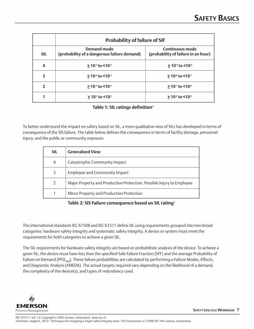
To better understand the impact on safety based on SIL, a more qualitative view of SILs has developed in terms ofconsequence of the SIS failure. The table below defines the consequence in terms of facility damage, personnelinjury, and the public or community exposure.
The international standards IEC 61508 and IEC 61511 define SIL using requirements grouped into two broadcategories: hardware safety integrity and systematic safety integrity. A device or system must meet therequirements for both categories to achieve a given SIL.
The SIL requirements for hardware safety integrity are based on probabilistic analysis of the device. To achieve agiven SIL, the device must have less than the specified Safe Failure Fraction (SFF) and the average Probability ofFailure on Demand (PFDavg). These failure probabilities are calculated by performing a Failure Modes, Effects, and Diagnostic Analysis (FMEDA). The actual targets required vary depending on the likelihood of a demand, the complexity of the device(s), and types of redundancy used.
SAFETY BASICS
SAFETY LIFECYCLE WORKBOOK 7
Demand mode Continuous modeSIL (probability of a dangerous failure demand) (probability of failure in an hour)
4 >_ 10-5 to <10-4 >_ 10-9 to <10-8
3 >_ 10-4 to <10-3 >_ 10-8 to <10-7
2 >_ 10-3 to <10-2 >_ 10-7 to <10-6
1 >_ 10-2 to <10-1 >_ 10-6 to <10-5
Probability of failure of SIF
SIL Generalized View
4 Catastrophic Community Impact
3 Employee and Community Impact
2 Major Property and Production Protection. Possible Injury to Employee
1 Minor Property and Production Protection
2IEC 61511-1 ed. 1.0 Copyright © 2003 Geneva, Switzerland. www.iec.ch3Summers, Angela E., Ph.D. “Techniques for Assigning a Target Safety Integrity Level.” ISA Transactions 37 (1998) 95-104. Geneva, Switzerland.
Table 1: SIL ratings definition2
Table 2: SIS Failure consequence based on SIL rating3
The SIL requirements for systematic safety integrity define a set of techniques and measures required to preventsystematic failures (bugs) from being designed into the device or system. These requirements are met byestablishing a rigorous development process as summarized in IEC 61508 Section 7.
Alternatively, the end user can self-certify the device by establishing that the device has sufficient operating historyto certify that the device has been “proven in use”.
Safety Instrumented System (SIS)
IEC 61511 defines a safety instrumented system (SIS) as an “instrumented system used to implement one or moresafety instrumented functions. An SIS is composed of any combination of sensor(s), logic solver(s), and finalelement(s).”
Safety Instrumented Function (SIF)
A SIF is designed to respond to the conditions within a plant that may be hazardous in themselves, or if no action istaken, could result in a hazardous event. Each SIF is assigned a specified SIL necessary to achieve functional safety.A SIF can be addressed through either a safety instrumented protection function or a safety instrumented controlfunction (SIS). A SIF is designed to respond to the conditions within a plant that may be hazardous in themselves,or if no action is taken, could result in a hazardous event. The challenge in SIF design is to select the equipmentthat mitigates the risk defined in the PHA, meets lifecycle cost goals and meets safety integrity goals.
How do SIFs and SILs relate to each other?
Based on the specific process application, a risk reduction factor (SIL rating) must be defined for each safety loop(SIF). The required SIL level of a specific SIF is determined by taking into account the required risk reduction factor(defined in the PHA process) that is to be provided by that function. SIL ratings vary for SIFs that operate incontinuous mode verses demand mode.
SAFETY BASICS
SAFETY LIFECYCLE WORKBOOK 8
INDUSTRY STANDARDSAs a benchmark for the reduction of risk associated with personnel, environmental and propertyprotection systems, international standards are now being used as guidelines to demonstratethat “best engineering practice” has been applied in the development of safety instrumentedsystems.
Complimenting a breadth of prescriptive standards traditionally used by the process industry, ithas become important to ensure that the safety system has been designed to fully comply withthe performance-based requirements of IEC 61508, ANSI/ISA 84, and/or IEC 61511.
While these standards and guidelines do not have the force of law in most countries, increasingdependence on SIS systems compels process manufacturers to ensure that a methodicalapproach is used to verify that the tolerable risk target has been achieved. In addition, theorganization must ensure and document individual and organizational competency in the designand functional safety management processes.
“All persons involved in any overall, E/E/PES or software safety lifecycle activity, includingmanagement activities, should have the appropriate training, technical knowledge,experience and qualifications relevant to the specific duties they have to perform. Thetraining, experience and qualifications of all persons... should be assessed in relation to theparticular application.”4
To meet industry’s demand for competency, process manufacturers and safety suppliers areincreasingly required to have formalized certification programs that ensure their employees aretrained and the safety applications are implemented in accordance with a process compliant toANSI/ISA 84, IEC61508 and IEC61511. To provide assurance of adherence to these standards,TÜV, Exida and other third-party certification organizations can audit these programs to ensurethat the certified quality processes are being strictly followed.
This section briefly reviews the performance-based standards (IEC 61508, IEC 61511, andANSI/ISA 84) to provide a context for their use and implementation.
IEC 61508 —SIS Hardware / Software Design Guidance
The IEC 61508 Functional Safety Standard published by the International ElectrotechnicalCommission (IEC) is applicable to a wide range of industries and applications and is written asprimary guidance for the supplier community in relation to the development of systems used forthe reduction of risk. Targeted at suppliers of safety-related equipment, IEC 61508 defines a set ofstandards for functional safety of electrical/ electronic/programmable electronic (E/E/PE ) safetyrelated systems.
Functional safety is defined as the overall program to ensure that the safety-related E/E/PE systembrings about a safe state when called upon to do so.
SAFETY LIFECYCLE WORKBOOK 94IEC 61508-1 ed. 1.0 Copyright © 1998 IEC Geneva, Switzerland. www.iec.ch
The IEC 61508 standard is composed of seven parts, including general safety requirements, specific system andsoftware requirements, and guidelines to applications. The standard is generic and can be used directly byindustry as a standalone standard. International standards organizations can use this standard as a basis for thedevelopment of industry-specific standards, such as the machinery industry sector, the process industry sector, orfor the nuclear industry sector. It is suggested that when evaluating a safety system, or related services, theuser/owner should consider selecting a company that is certified to IEC 61508 by an independent third-party, suchas TÜV or Exida.
The IEC 61508 standard requires the product developer to validate the safety integrity of a system considering allcauses of failure, both random hardware failures and systematic failures, including hardware failures, softwareinduced failures, failures due to electrical interference and other environmental stresses.
IEC 61508 —SIS Hardware Design Validation
Some of these types of failures, in particular random hardware failures, may be quantified using such measures asthe failure rate in the dangerous mode of failure or the probability of a safety-related protection system failing tooperate on demand.
A Failure Modes, Effects, and Diagnostic Analysis (FMEDA) should be performed on the safety component as partof a full assessment according to the functional safety standard IEC 61508. This full assessment includes anassessment of all fault avoidance and fault control measures during hardware and software development anddemonstrates full compliance with IEC 61508 to the end-user.
The FMEDA document describes the results of the hardware assessment to determine the fault behavior andfailure rates from which the Safe Failure Fraction (SFF) and the average Probability of Failure on Demand (PFDavg)are determined. It provides the safety instrumentation engineer with the required failure data as per IEC.
IEC 61508 —SIS Software Design Validation
IEC 61508 Part 3 covers the software requirements within this standard. It applies to any software used in a safety-related system or software used to develop a safety-related system. This software is specifically referred to assafety-related software. This part of the standard provides details of the software safety life cycle, a process to beused when developing software.
INDUSTRY STANDARDS
10 SAFETY LIFECYCLE WORKBOOK
To insure integrity in the software used in safety systems, the IEC 61508 standard requires that the SIS vendor havea rigorous Software Quality Plan as outlined in Part 3; Clause 7, including the following software safety lifecyclerequirements:
7.1 General Requirements7.2 Software safety requirements specification7.3 Software safety validation planning7.4 Software design and development7.5 Programmable electronics integration (hardware and software)7.6 Software operation and modification procedures7.7 Software safety validation7.8 Software modification7.9 Software verification
In the standard IEC 61508-3 Annex A provides a listing of “techniques and measures” used for softwaredevelopment where different development techniques are chosen depending on the SIL level of the software.
Annex B has nine detailed tables of design and coding standards as well as analysis and testing techniques that areto be used in the safety-related software development, depending on SIL level of the software and in some casesthe choice of the development team.
IEC 61511 — SIS Design Guidance for the Process Industry Sector
Since the publication of the IEC 61508 safety standard and, more recently, the IEC61511 standard for the processindustry sector (including ANSI/ISA 84.00.01-2004), interest in performing rigorous hazard and risk analysis andapplying certified safety instrumented systems has increased considerably within the user community.
These standards provide guidance on best practice and offer recommendations, but do not absolve their users ofresponsibility for safety. The standards deal not only with technical issues but also include the planning,documentation and assessment of all activities required to manage safety throughout the entire life of a system.
The standard is based on two fundamental concepts: the safety life cycle and safety integrity levels. The safety lifecycle is defined as an engineering process that includes all of the steps necessary to achieve required functionalsafety. The standard includes extensive documentation requirements and utilizes statistical techniques for theprediction of hardware failures. The standard focuses attention on risk-based safety-related system design andrequires significant attention to detail that is vital to safety system design.
The basic philosophy behind the safety life cycle is to develop and document a safety plan, execute that plan,document its execution (to show that the plan has been met) and continue to follow that safety plan throughdecommissioning — with further appropriate documentation being generated throughout the life of the system.
INDUSTRY STANDARDS
SAFETY LIFECYCLE WORKBOOK 11
Changes along the way must similarly follow the pattern of planning, execution, validation, and documentation.The IEC61511 standard is comprised of three parts which mirror the structure of ANSI/ISA-84.00.01-2004 forconsistency:
IEC 61511-1: Framework, definitions, system, hardware and software requirements (Serves as the basis for this workbook).
IEC 61511-2: Guidelines on the application of IEC 61511-1IEC 61511-3: Guidance for the determination of the required safety integrity levels
ANSI/ISA-84.00.01-2004 SIS for the Process Industry Sector
This international standard addresses the application of safety instrumented systems based on the use ofelectrical/electronic/programmable electronic technology. This standard has fully adopted the processes andphilosophies detailed in the IEC 61511 document with the exception of a “grandfather” clause which provides aprovision to allow safety systems built prior to the issuance of the 1996 standard to remain in operation by stating:
“For existing SIS designed and constructed in accordance with codes, standards, or practices prior to theissue of this standard (e.g., ANSI/ISA-84.01-1996), the owner/operator shall determine that the equipmentis designed, maintained, inspected, tested, and operating in a safe manner.”5
The concept of the "grandfather clause” originated with OSHA 1910.119. The grandfather clause's intent is torecognize prior good engineering practices and to allow their continued use with regard to existing SIS systems.This alignment is intended to lead to a high level of consistency of underlying principles, terminology, andinformation within the process industries worldwide.
In accordance with IEC 61511, the ANSI/ISA-84 addresses all safety life-cycle phases from initial concept, design,implementation, operation and maintenance through to decommissioning. It requires a process hazard and riskassessment to be carried out to enable the specification for safety instrumented systems and sets out an approachfor all safety life-cycle activities to maintain these defined requirements.
INDUSTRY STANDARDS
12 SAFETY LIFECYCLE WORKBOOK
5 Instrumentation, Systems, and Automation Society (ISA), ANSI/ISA 84.01-2004, “Application of Safety Instrumented Systems (SIS) for the Process Industry,”Research Triangle Park, NC (2004).
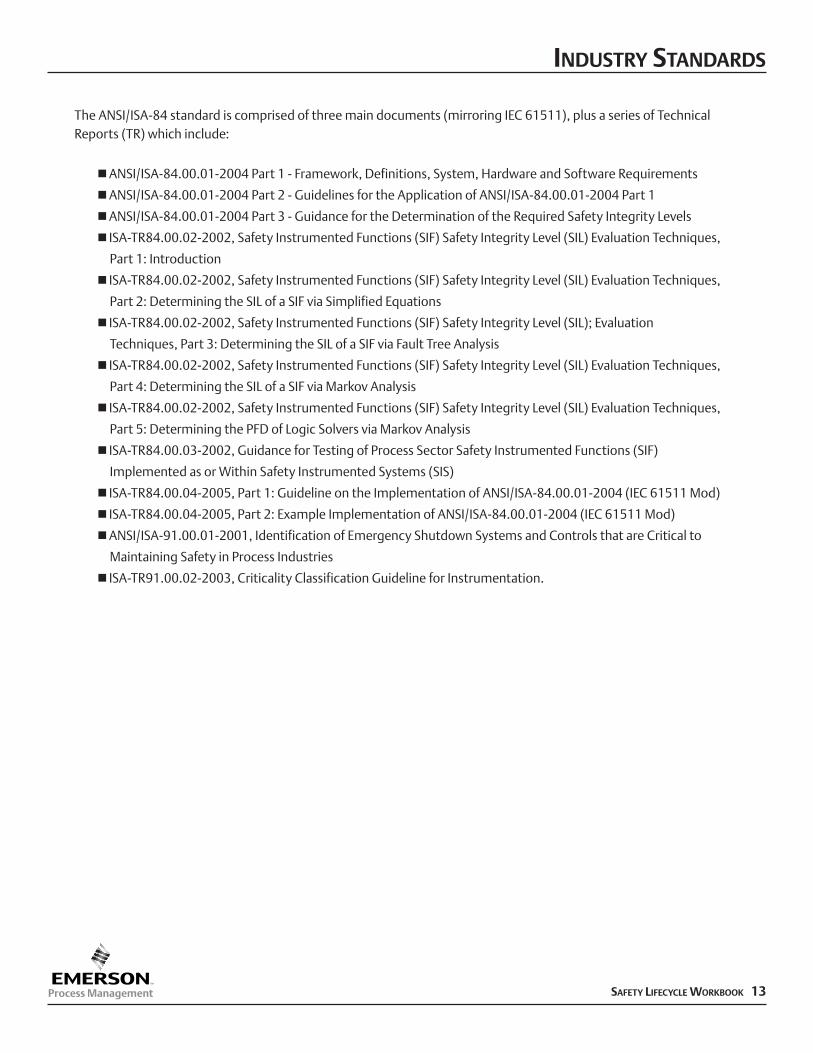
The ANSI/ISA-84 standard is comprised of three main documents (mirroring IEC 61511), plus a series of TechnicalReports (TR) which include:
nANSI/ISA-84.00.01-2004 Part 1 - Framework, Definitions, System, Hardware and Software Requirements
nANSI/ISA-84.00.01-2004 Part 2 - Guidelines for the Application of ANSI/ISA-84.00.01-2004 Part 1
nANSI/ISA-84.00.01-2004 Part 3 - Guidance for the Determination of the Required Safety Integrity Levels
n ISA-TR84.00.02-2002, Safety Instrumented Functions (SIF) Safety Integrity Level (SIL) Evaluation Techniques,
Part 1: Introduction
n ISA-TR84.00.02-2002, Safety Instrumented Functions (SIF) Safety Integrity Level (SIL) Evaluation Techniques,
Part 2: Determining the SIL of a SIF via Simplified Equations
n ISA-TR84.00.02-2002, Safety Instrumented Functions (SIF) Safety Integrity Level (SIL); Evaluation
Techniques, Part 3: Determining the SIL of a SIF via Fault Tree Analysis
n ISA-TR84.00.02-2002, Safety Instrumented Functions (SIF) Safety Integrity Level (SIL) Evaluation Techniques,
Part 4: Determining the SIL of a SIF via Markov Analysis
n ISA-TR84.00.02-2002, Safety Instrumented Functions (SIF) Safety Integrity Level (SIL) Evaluation Techniques,
Part 5: Determining the PFD of Logic Solvers via Markov Analysis
n ISA-TR84.00.03-2002, Guidance for Testing of Process Sector Safety Instrumented Functions (SIF)
Implemented as or Within Safety Instrumented Systems (SIS)
n ISA-TR84.00.04-2005, Part 1: Guideline on the Implementation of ANSI/ISA-84.00.01-2004 (IEC 61511 Mod)
n ISA-TR84.00.04-2005, Part 2: Example Implementation of ANSI/ISA-84.00.01-2004 (IEC 61511 Mod)
nANSI/ISA-91.00.01-2001, Identification of Emergency Shutdown Systems and Controls that are Critical to
Maintaining Safety in Process Industries
n ISA-TR91.00.02-2003, Criticality Classification Guideline for Instrumentation.
INDUSTRY STANDARDS
SAFETY LIFECYCLE WORKBOOK 13
INDUSTRY STANDARDS
SAFETY LIFECYCLE WORKBOOK 14
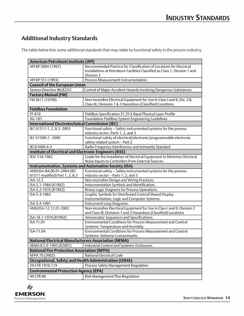
Additional Industry Standards
The table below lists some additional standards that may relate to functional safety in the process industry.
SAFETY INSTRUMENTED SYSTEMSARCHITECTURE
A Safety Instrumented System (SIS) is defined as an instrumented system used to implement oneor more safety instrumented functions (SIF) composed of any combination of sensor(s), logicsolver(s), and final elements(s). These systems are designed to take action to bring theequipment under control to a safe state when a process is beyond the range of normal operatinglimits and other layers of control, including operators and the basic process control system(BPCS), are unable keep the process within safe operating limits.
There are two basic architectures for SIS systems:
1. Standalone SIS systems are isolated systems; or they can be integrated into the controlsystem by mapping the necessary data across a physical communications layer to provideintegrated control and operator access to safety information.
2. Integrated Control and Safety Systems (ICSS) are based upon a native communicationsstructure between the BPCS and SIS systems–sharing engineering, operations, andmaintenance environments, with physically separate and independent power supplies,communication channels, and control hardware/software functions.
Separation and Diversity
With either architecture, experienced industry professionals support a rigorous philosophy ofseparation and diversification for the BPCS and SIS.
IEC61511 defines this separation in the following clauses:
9.5.2 Assessment shall consider SIF independency, diversity and physical separation.
10.3.1 “Note: Non-safety instrumented functions may be carried out by the SIS to ensure orderly shutdown or faster startup. These should be separated from the safety instrumented functions.”5
11.2.4: “If it is intended not to qualify the basic process control system to this standard, then the basic process control system shall be designed to be separate and independent to the extent that the functional integrity of the safety instrumented system is not compromised.”6
The design requirements detailed in IEC61508 focus on the separation of safety and BPCS controlfunctions in different controllers for the following reasons:
n Independent failures–Minimize the risk of simultaneous failure of a control system along with the SIS.
nSecurity–Prevent changes in a control system from causing any change or corruption in theassociated SIS.
SAFETY LIFECYCLE WORKBOOK 156IEC 61511-1 ed. 1.0 Copyright © 2003 Geneva, Switzerland. www.iec.ch
nDifferent requirements for safety controllers–A safety system is normally designed to fail in a safe way; whereas, a BPCS is usually designed to maximize process availability.
nSafety functionality–An SIS is based upon the functionality of extended diagnostics, special software error checking, protected data storage and fault tolerance. The design of the BPCS should include not causing any change or corruption in the associated SIS.
Stand Alone Safety Instrumented Systems
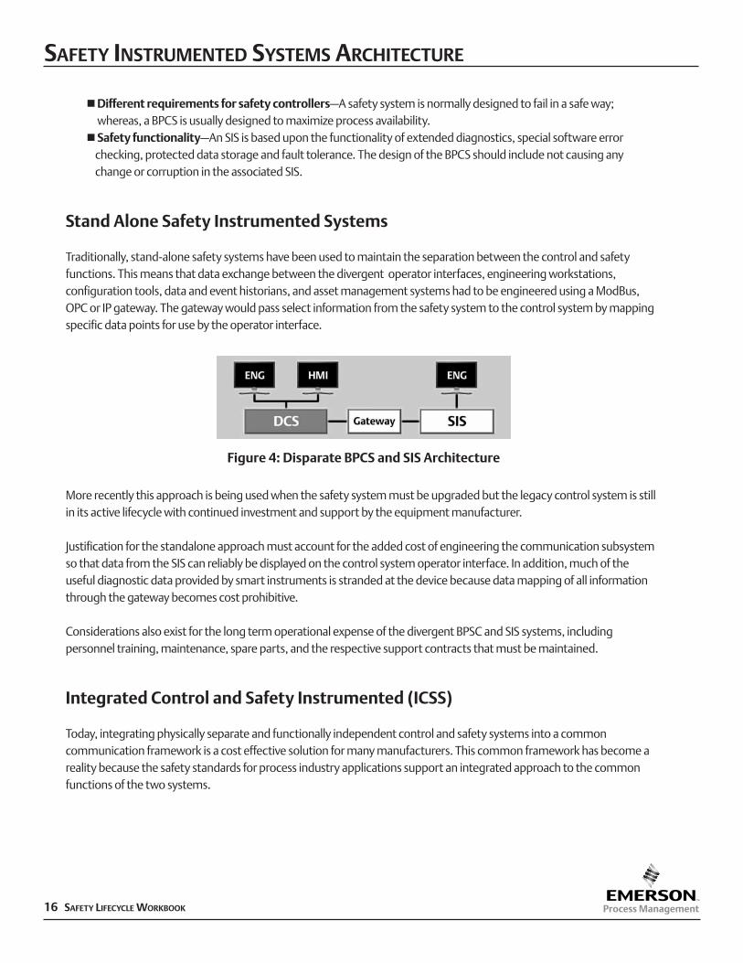
Traditionally, stand-alone safety systems have been used to maintain the separation between the control and safetyfunctions. This means that data exchange between the divergent operator interfaces, engineering workstations,configuration tools, data and event historians, and asset management systems had to be engineered using a ModBus,OPC or IP gateway. The gateway would pass select information from the safety system to the control system by mappingspecific data points for use by the operator interface.
More recently this approach is being used when the safety system must be upgraded but the legacy control system is stillin its active lifecycle with continued investment and support by the equipment manufacturer.
Justification for the standalone approach must account for the added cost of engineering the communication subsystemso that data from the SIS can reliably be displayed on the control system operator interface. In addition, much of theuseful diagnostic data provided by smart instruments is stranded at the device because data mapping of all informationthrough the gateway becomes cost prohibitive.
Considerations also exist for the long term operational expense of the divergent BPSC and SIS systems, includingpersonnel training, maintenance, spare parts, and the respective support contracts that must be maintained.
Integrated Control and Safety Instrumented (ICSS)
Today, integrating physically separate and functionally independent control and safety systems into a commoncommunication framework is a cost effective solution for many manufacturers. This common framework has become areality because the safety standards for process industry applications support an integrated approach to the commonfunctions of the two systems.
SAFETY INSTRUMENTED SYSTEMS ARCHITECTURE
Figure 4: Disparate BPCS and SIS Architecture
16 SAFETY LIFECYCLE WORKBOOK
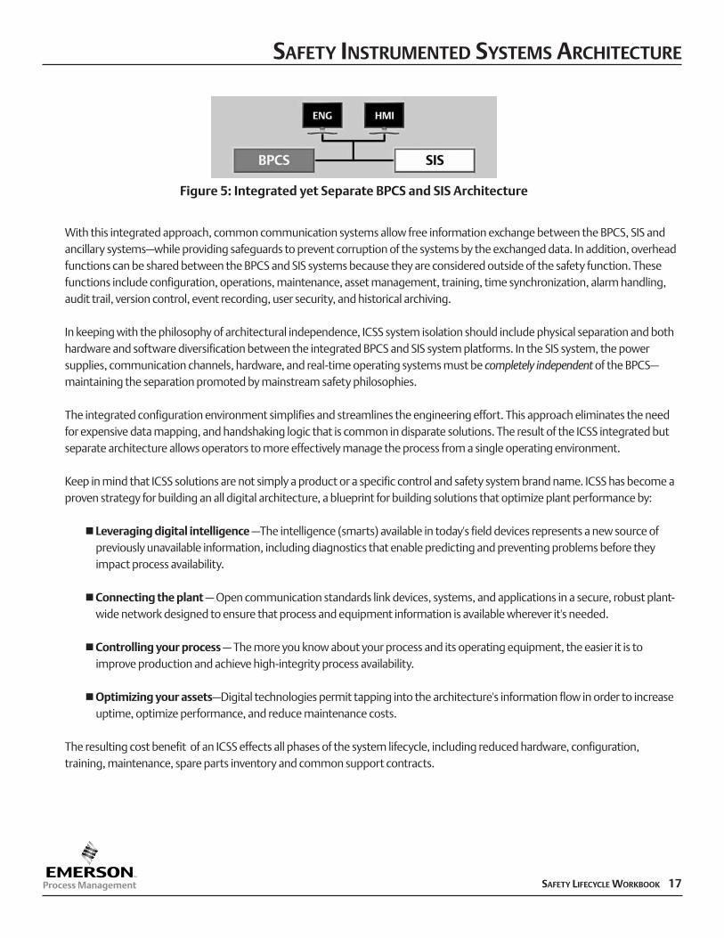
With this integrated approach, common communication systems allow free information exchange between the BPCS, SIS andancillary systems–while providing safeguards to prevent corruption of the systems by the exchanged data. In addition, overheadfunctions can be shared between the BPCS and SIS systems because they are considered outside of the safety function. Thesefunctions include configuration, operations, maintenance, asset management, training, time synchronization, alarm handling,audit trail, version control, event recording, user security, and historical archiving.
In keeping with the philosophy of architectural independence, ICSS system isolation should include physical separation and bothhardware and software diversification between the integrated BPCS and SIS system platforms. In the SIS system, the powersupplies, communication channels, hardware, and real-time operating systems must be completely independent of the BPCS–maintaining the separation promoted by mainstream safety philosophies.
The integrated configuration environment simplifies and streamlines the engineering effort. This approach eliminates the needfor expensive data mapping, and handshaking logic that is common in disparate solutions. The result of the ICSS integrated butseparate architecture allows operators to more effectively manage the process from a single operating environment.
Keep in mind that ICSS solutions are not simply a product or a specific control and safety system brand name. ICSS has become aproven strategy for building an all digital architecture, a blueprint for building solutions that optimize plant performance by:
nLeveraging digital intelligence –The intelligence (smarts) available in today's field devices represents a new source of previously unavailable information, including diagnostics that enable predicting and preventing problems before they impact process availability.
nConnecting the plant – Open communication standards link devices, systems, and applications in a secure, robust plant-wide network designed to ensure that process and equipment information is available wherever it's needed.
nControlling your process – The more you know about your process and its operating equipment, the easier it is to improve production and achieve high-integrity process availability.
nOptimizing your assets–Digital technologies permit tapping into the architecture's information flow in order to increase uptime, optimize performance, and reduce maintenance costs.
The resulting cost benefit of an ICSS effects all phases of the system lifecycle, including reduced hardware, configuration,training, maintenance, spare parts inventory and common support contracts.
SAFETY INSTRUMENTED SYSTEMS ARCHITECTURE
Figure 5: Integrated yet Separate BPCS and SIS Architecture
SAFETY LIFECYCLE WORKBOOK 17
SAFETY INSTRUMENTED SYSTEMS ARCHITECTURE
18 SAFETY LIFECYCLE WORKBOOK
This page intentionally left blank.
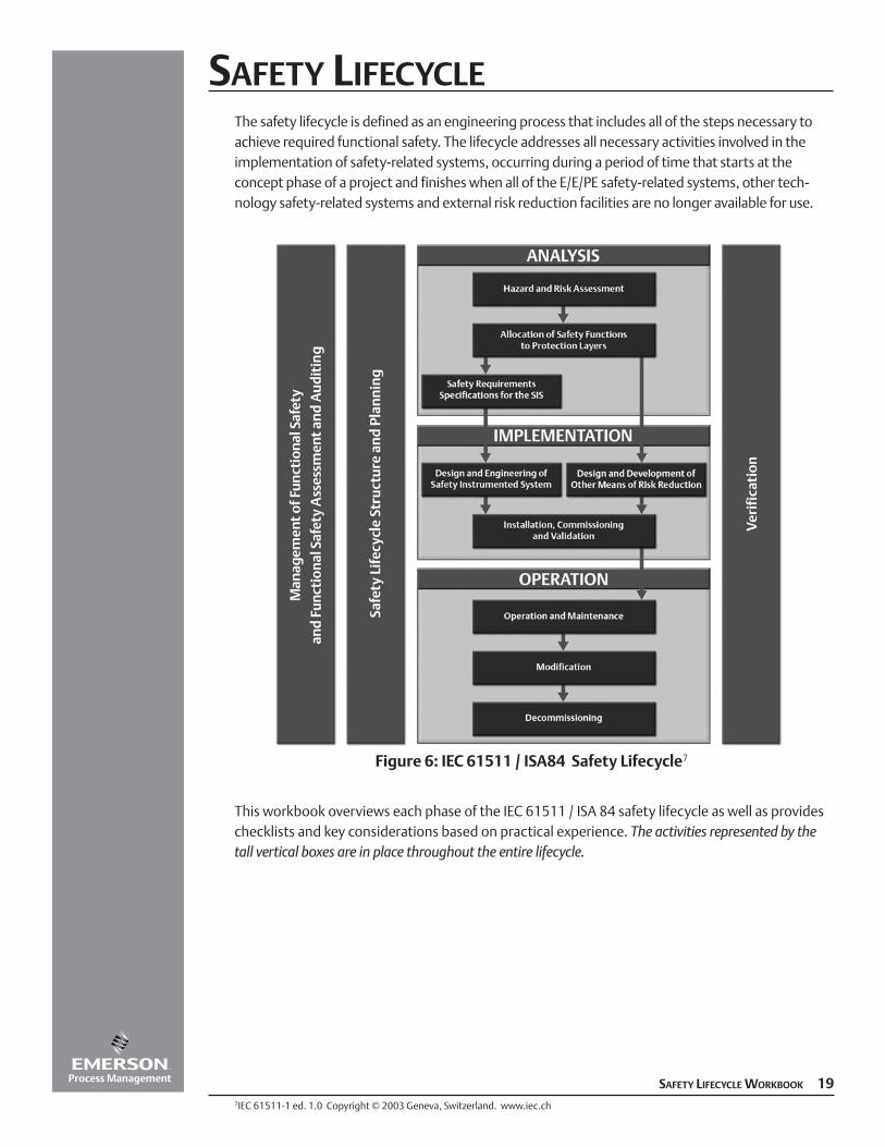
SAFETY LIFECYCLEThe safety lifecycle is defined as an engineering process that includes all of the steps necessary toachieve required functional safety. The lifecycle addresses all necessary activities involved in theimplementation of safety-related systems, occurring during a period of time that starts at theconcept phase of a project and finishes when all of the E/E/PE safety-related systems, other tech-nology safety-related systems and external risk reduction facilities are no longer available for use.
This workbook overviews each phase of the IEC 61511 / ISA 84 safety lifecycle as well as provideschecklists and key considerations based on practical experience. The activities represented by thetall vertical boxes are in place throughout the entire lifecycle.
SAFETY LIFECYCLE WORKBOOK 19
Figure 6: IEC 61511 / ISA84 Safety Lifecycle7
7IEC 61511-1 ed. 1.0 Copyright © 2003 Geneva, Switzerland. www.iec.ch
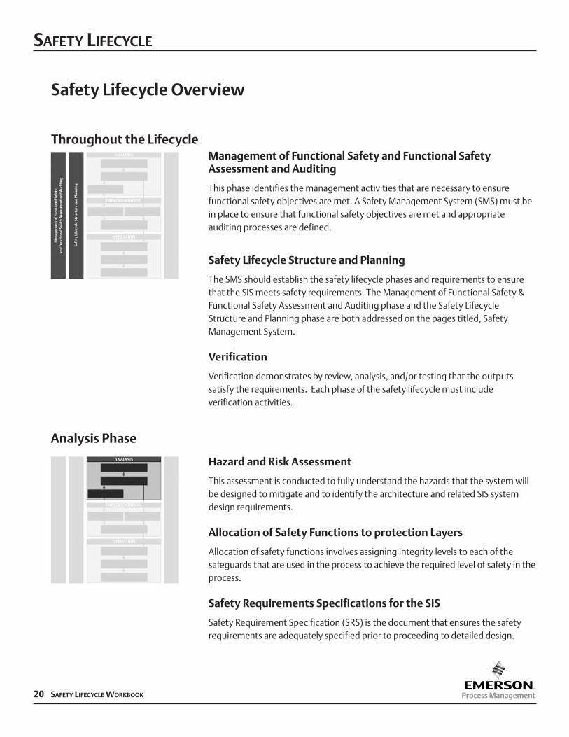
Safety Lifecycle Overview
Throughout the LifecycleManagement of Functional Safety and Functional SafetyAssessment and Auditing
This phase identifies the management activities that are necessary to ensurefunctional safety objectives are met. A Safety Management System (SMS) must bein place to ensure that functional safety objectives are met and appropriateauditing processes are defined.
Safety Lifecycle Structure and Planning
The SMS should establish the safety lifecycle phases and requirements to ensurethat the SIS meets safety requirements. The Management of Functional Safety &Functional Safety Assessment and Auditing phase and the Safety LifecycleStructure and Planning phase are both addressed on the pages titled, SafetyManagement System.
Verification
Verification demonstrates by review, analysis, and/or testing that the outputssatisfy the requirements. Each phase of the safety lifecycle must includeverification activities.
Hazard and Risk Assessment
This assessment is conducted to fully understand the hazards that the system willbe designed to mitigate and to identify the architecture and related SIS systemdesign requirements.
Allocation of Safety Functions to protection Layers
Allocation of safety functions involves assigning integrity levels to each of thesafeguards that are used in the process to achieve the required level of safety in theprocess.
Safety Requirements Specifications for the SIS
Safety Requirement Specification (SRS) is the document that ensures the safetyrequirements are adequately specified prior to proceeding to detailed design.
SAFETY LIFECYCLE
20 SAFETY LIFECYCLE WORKBOOK
Analysis Phase
SAFETY LIFECYCLE
SAFETY LIFECYCLE WORKBOOK 21
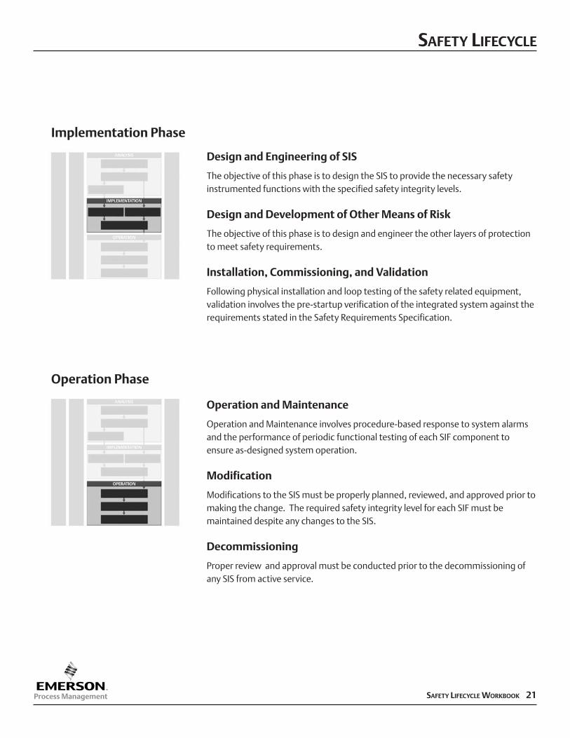
Design and Engineering of SIS
The objective of this phase is to design the SIS to provide the necessary safetyinstrumented functions with the specified safety integrity levels.
Design and Development of Other Means of Risk
The objective of this phase is to design and engineer the other layers of protectionto meet safety requirements.
Installation, Commissioning, and Validation
Following physical installation and loop testing of the safety related equipment,validation involves the pre-startup verification of the integrated system against therequirements stated in the Safety Requirements Specification.
Implementation Phase
Operation and Maintenance
Operation and Maintenance involves procedure-based response to system alarmsand the performance of periodic functional testing of each SIF component toensure as-designed system operation.
Modification
Modifications to the SIS must be properly planned, reviewed, and approved prior tomaking the change. The required safety integrity level for each SIF must bemaintained despite any changes to the SIS.
Decommissioning
Proper review and approval must be conducted prior to the decommissioning ofany SIS from active service.
Operation Phase
Safety Management System
The manufacturer should have a written program to define the overall strategy withrespect to Safety Instrumented Systems (SIS). This policy declares the use of a safety lifecycle approach that meets the requirements of the IEC 61511 standard, from hazardousanalysis to specification to system validation and eventual decommissioning. The scopeof the Safety Management System (SMS) is separate and distinct from all other generalhealth and safety measures that are necessary for the achievement of safety in theworkplace.
The SMS addresses the ongoing Management of Functional Safety and Functional SafetyAssessment and Auditing, as well as the Safety Lifecycle Structure and Planning phases ofthe lifecycle and the corresponding activities.
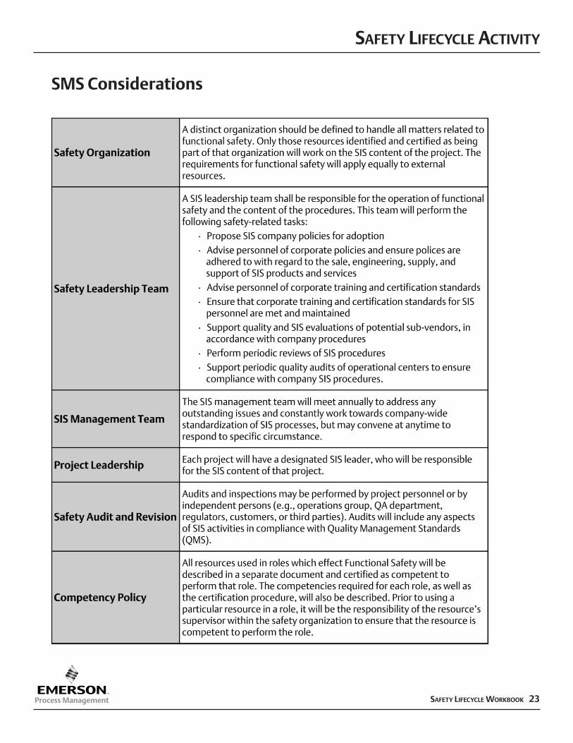
The SMS should address the following:nFunctional safety management
qSafety organizationq Safety leadership teamqSIS management teamqProject leadershipqSafety audit and revisionqCompetency policy
nSafety lifecyclenSupporting processes
q Selection and approval of contractorsq Selection and approval of supplier equipmentq Selection and approval of safety toolsq Safety modification process.
Documented Safety Management System
Review and approval of SMS and associated auditing processes before the project begins
Process manufacturer
SAFETY LIFECYCLE ACTIVITY
22 SAFETY LIFECYCLE WORKBOOK
Objective
Description
Outputs
Verification Activity
Responsibility
SAFETY LIFECYCLE ACTIVITY
SAFETY LIFECYCLE WORKBOOK 23
SMS Considerations
Verification
A Safety Verification Plan manages changes and demonstrates by review, analysis and/ortesting that the system satisfies the requirements defined in the Safety RequirementsSpecifications.
The Safety Verification Plan (SVP) should address:nTechnical basis for the changen Impact of the change on safety and healthnProcedures to be used for non-conformancesnActivities to take place and items to be verifiednAny modification to operating proceduresnTime period for the changenAuthorization requirements.
Employers should notify and train affected employees and update process safetyinformation and operating procedures as necessary.
nProject-specific Safety Verification PlannOperational Safety Verification PlannResults of verification efforts with appropriate authorization
During project implementation, a project-specific SVP provides a systematic andstructured list of all activities for each stage of the safety lifecycle, as well as verificationof these completed activities.
During operation, a separate SVP defines the ongoing process to manage and verifychanges.
Project-specific Safety Verification Plan:Process manufacturer and service provider
Operational Safety Verification Plan: Process manufacturer
Results of verification efforts: Party making the changes
SAFETY LIFECYCLE ACTIVITY
24 SAFETY LIFECYCLE WORKBOOK
Objective
Description
Outputs
Verification Activity
Responsibility
SAFETY LIFECYCLE ACTIVITY
SAFETY LIFECYCLE WORKBOOK 25
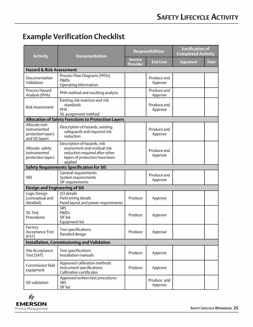
Example Verification Checklist
SAFETY LIFECYCLE
26 SAFETY LIFECYCLE WORKBOOK
Hazard and Risk Assessment
Analysis Phase
This assessment is conducted to identify hazards and hazardous events of the processand associated equipment, process risks, requirements for risk reduction, and safetyfunctions necessary to achieve an acceptable level of risk.
A hazard and risk assessment is carried out on the process and associated equipment.
A description of the hazards, of the required safety function(s), and of the associatedrisks, including:
n Identified hazardous events and contributing factorsnConsequences and likelihood of the eventnConsideration of operational conditions (startup, normal, shutdown)nRequired risk reduction to achieve required safetynReferences and assumptionsnAllocation of safety functions to layers of protectionn Identified safety functions as SIFs.
Process manufacturer
Objective
Description
Outputs
Responsibility
Each phase of the lifecycle must include Verification activities. Verification demonstrates by review, analysis and/or testing
that the outputs satisfy the requirements.
This assessment is conducted to fully understand the hazards that the system will be designed to mitigate and toidentify the architecture and related SIS system design requirements.
SAFETY LIFECYCLE
SAFETY LIFECYCLE WORKBOOK 27
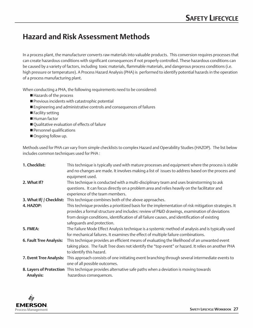
Hazard and Risk Assessment Methods
In a process plant, the manufacturer converts raw materials into valuable products. This conversion requires processes thatcan create hazardous conditions with significant consequences if not properly controlled. These hazardous conditions canbe caused by a variety of factors, including toxic materials, flammable materials, and dangerous process conditions (i.e.high pressure or temperature). A Process Hazard Analysis (PHA) is performed to identify potential hazards in the operationof a process manufacturing plant.
When conducting a PHA, the following requirements need to be considered: nHazards of the processnPrevious incidents with catastrophic potentialnEngineering and administrative controls and consequences of failuresnFacility settingnHuman factornQualitative evaluation of effects of failurenPersonnel qualificationsnOngoing follow up.
Methods used for PHA can vary from simple checklists to complex Hazard and Operability Studies (HAZOP). The list belowincludes common techniques used for PHA :
1. Checklist: This technique is typically used with mature processes and equipment where the process is stableand no changes are made. It involves making a list of issues to address based on the process andequipment used.
2. What If? This technique is conducted with a multi-disciplinary team and uses brainstorming to askquestions. It can focus directly on a problem area and relies heavily on the facilitator and experience of the team members.
3. What If/ / Checklist: This technique combines both of the above approaches.4. HAZOP: This technique provides a prioritized basis for the implementation of risk mitigation strategies. It
provides a formal structure and includes: review of P&ID drawings, examination of deviations from design conditions, identification of all failure causes, and identification of existing safeguards and protection.
5. FMEA: The Failure Mode Effect Analysis technique is a systemic method of analysis and is typically used for mechanical failures. It examines the effect of multiple failure combinations.
6. Fault Tree Analysis: This technique provides an efficient means of evaluating the likelihood of an unwanted event taking place. The Fault Tree does not identify the “top event” or hazard. It relies on another PHA to identify this hazard.
7. Event Tree Analysis: This approach consists of one initiating event branching through several intermediate events toone of all possible outcomes.
8. Layers of Protection This technique provides alternative safe paths when a deviation is moving towardsAnalysis: hazardous consequences.
SAFETY LIFECYCLE ACTIVITY
28 SAFETY LIFECYCLE WORKBOOK
Allocation of Safety Functions to the Protection Layers
This phase allocates safety functions to protection layers and for each safetyinstrumented function (SIF), the associated safety integrity level (SIL).
This allocation activity includes the analysis of the protection needed for specific safetyfunctions for the purpose of prevention, control or mitigation of hazards from theprocess and its associated equipment.
A description of allocation of safety requirements, including:nDetermine the allocation of safety functions to protection layersnDefine SIFsnDetermine SIL for each SIF.
Process manufacturer
Objective
Description
Outputs
Responsibility
Each phase of the lifecycle must include Verification activities. Verification demonstrates by review, analysis and/or testing
that the outputs satisfy the requirements.
Analysis Phase
Allocation of Safety Functions involves assigning integrity levels to each of the safeguards that are used inthe process to achieve the required level of safety the that process.
SAFETY LIFECYCLE ACTIVITY
SAFETY LIFECYCLE WORKBOOK 29
SIL Assignment
Once the hazard and risk assessment has is completed, the risk associated with the process in terms of event severity and likelihoodshould be understood. There are no regulations that assign a SIL to particular processes or hazards. The assignment of SIL is acompany decision based on risk management and risk tolerance philosophy.
“ANSI/ISA S84.01-1996 does mandate that companies should design their safety instrumented systems (SIS) to be consistent with similar operating process units within their own companies and at other companies. Likewise, in the US, OSHA PSM andEPA RMP require that industry standards and good engineering practice be used in the design and operation of process facilities. This means that the assignment of safety integrity levels must be carefully performed and thoroughly documented.”8
Various methods, both qualitative and quantitative, are used to convert PHA data into SIL levels. The most common methods arelisted below:
nModified HAZOP: This approach is an extension of the HAZOP process and relies on the subjective assignment of SIL basedon the team’s expertise. Since this method is subjective, team member consistency from project to project needs to be addressed.
nConsequence only: This method uses an estimation of the potential consequence of the incident and does not take into effect the frequency. Therefore, all incidents involving a fatality would have the same SIL regardless of likelihood. This approach is the simplest to use, but also the most conservative.
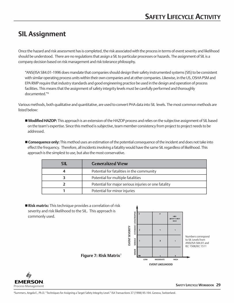
nRisk matrix: This technique provides a correlation of riskseverity and risk likelihood to the SIL. This approach is commonly used.
SIL Generalized View
4 Potential for fatalities in the community
3 Potential for multiple fatalities
2 Potential for major serious injuries or one fatality
1 Potential for minor injuries
MIN
OR
SE
RIO
US
EX
TEN
SIV
E C
ATA
STRO
PHIC
EVEN
T SE
VER
ITY
EVENT LIKELIHOOD
Numbers correspondto SIL Levels fromANSI/ISA S84.01 andIEC 1508/IEC 1511
LOW MODERATE HIGH
NOTACCEPTABLE
RISK
3 3
3 3
32
2
2NR 1
1
8Summers, Angela E., Ph.D. “Techniques for Assigning a Target Safety Integrity Level.” ISA Transactions 37 (1998) 95-104. Geneva, Switzerland.
Figure 7: Risk Matrix7
SAFETY LIFECYCLE ACTIVITY
30 SAFETY LIFECYCLE WORKBOOK
SIL Assignment
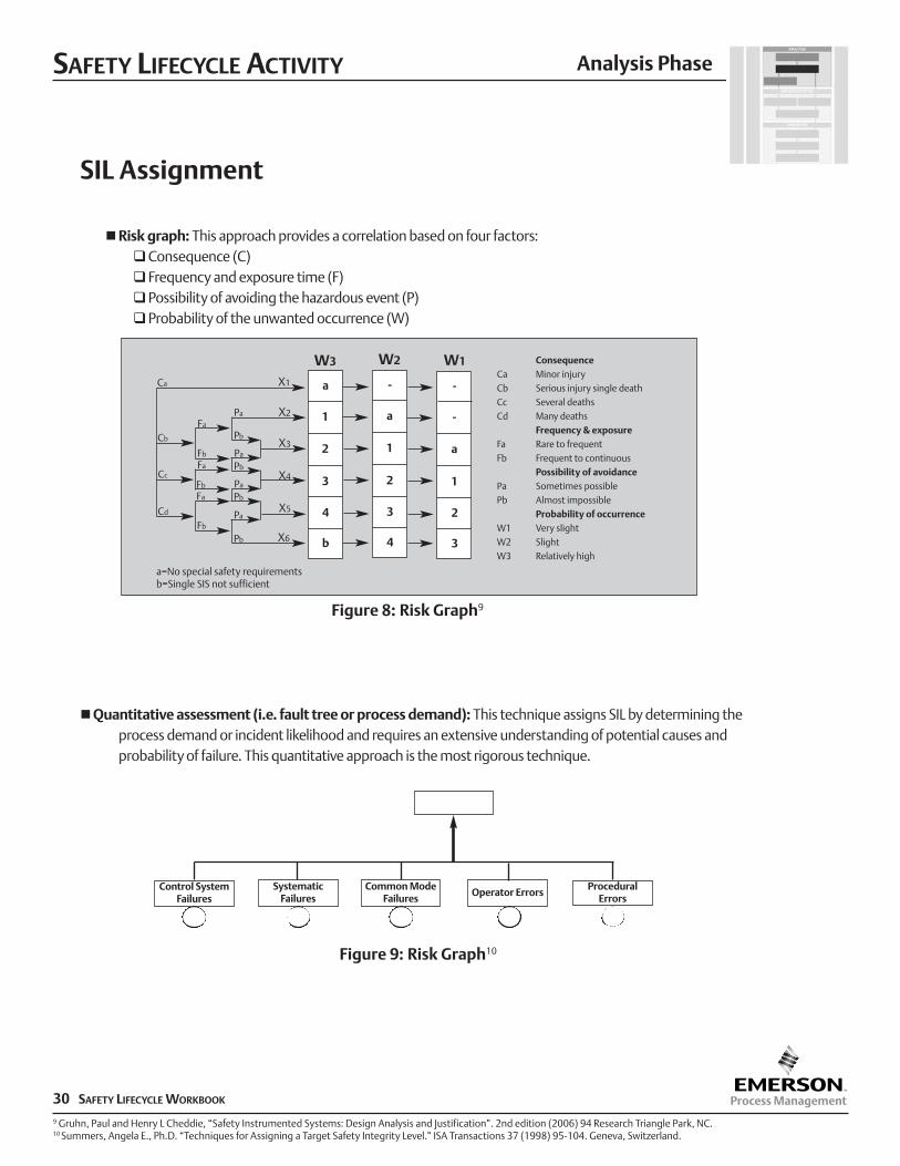
nRisk graph: This approach provides a correlation based on four factors:qConsequence (C)qFrequency and exposure time (F)qPossibility of avoiding the hazardous event (P)qProbability of the unwanted occurrence (W)
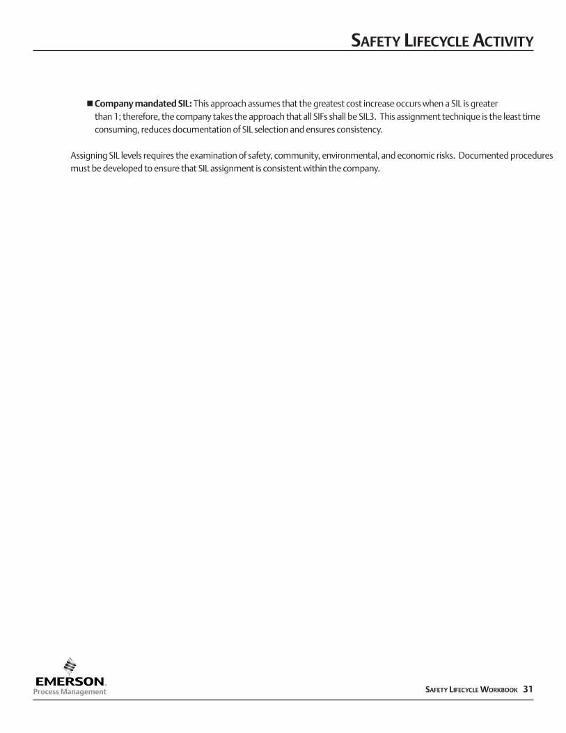
nQuantitative assessment (i.e. fault tree or process demand): This technique assigns SIL by determining theprocess demand or incident likelihood and requires an extensive understanding of potential causes and probability of failure. This quantitative approach is the most rigorous technique.
Analysis Phase
Control SystemFailures
SystematicFailures
Common ModeFailures
Operator ErrorsProcedural
Errors
9 Gruhn, Paul and Henry L Cheddie, “Safety Instrumented Systems: Design Analysis and Justification”. 2nd edition (2006) 94 Research Triangle Park, NC.10 Summers, Angela E., Ph.D. “Techniques for Assigning a Target Safety Integrity Level.” ISA Transactions 37 (1998) 95-104. Geneva, Switzerland.
a
W3 W2 W1
X1
X2Pa
Fa
Fb
Fa
Fa
Fb
Fb
Cd
Cc
Cb
Ca
Pb
Pa
Pb
Pa
Pb
Pa
Pb
X3
X4
X5
X6
1
2
3
4
b
-
a
1
2
3
4
-
-
a
1
2
3
Figure 8: Risk Graph9
Figure 9: Risk Graph10
ConsequenceCa Minor injuryCb Serious injury single deathCc Several deathsCd Many deaths
Frequency & exposureFa Rare to frequentFb Frequent to continuous
Possibility of avoidancePa Sometimes possiblePb Almost impossible
Probability of occurrenceW1 Very slightW2 SlightW3 Relatively high
a=No special safety requirementsb=Single SIS not sufficient
SAFETY LIFECYCLE ACTIVITY
SAFETY LIFECYCLE WORKBOOK 31
nCompany mandated SIL: This approach assumes that the greatest cost increase occurs when a SIL is greater than 1; therefore, the company takes the approach that all SIFs shall be SIL3. This assignment technique is the least time consuming, reduces documentation of SIL selection and ensures consistency.
Assigning SIL levels requires the examination of safety, community, environmental, and economic risks. Documented proceduresmust be developed to ensure that SIL assignment is consistent within the company.
SAFETY LIFECYCLE ACTIVITY
32 SAFETY LIFECYCLE WORKBOOK
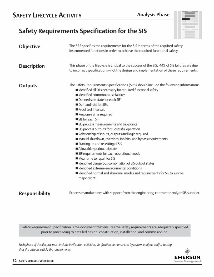
Safety Requirements Specification for the SIS
The SRS specifies the requirements for the SIS in terms of the required safetyinstrumented functions in order to achieve the required functional safety.
This phase of the lifecycle is critical to the success of the SIS. 44% of SIS failures are dueto incorrect specifications–not the design and implementation of these requirements.
The Safety Requirements Specifications (SRS) should include the following information:n Identified all SIFs necessary for required functional safetyn Identified common cause failuresnDefined safe state for each SIFnDemand rate for SIFsnProof test intervalsnResponse time requirednSIL for each SIFnSIS process measurements and trip pointsnSIS process outputs for successful operationnRelationship of inputs, outputs and logic requirednManual shutdown, overrides, inhibits, and bypass requirementsnStarting up and resetting of SISnAllowable spurious trip ratenSIF requirements for each operational modenMeantime to repair for SISn Identified dangerous combination of SIS output statesn Identified extreme environmental conditionsn Identified normal and abnormal modes and requirements for SIS to survive
major event.
Process manufacturer with support from the engineering contractor and/or SIS supplier
Objective
Description
Outputs
Responsibility
Analysis Phase
Each phase of the lifecycle must include Verification activities. Verification demonstrates by review, analysis and/or testing
that the outputs satisfy the requirements.
Safety Requirement Specification is the document that ensures the safety requirements are adequately specifiedprior to proceeding to detailed design, construction, installation, and commissioning.
SAFETY LIFECYCLE ACTIVITY
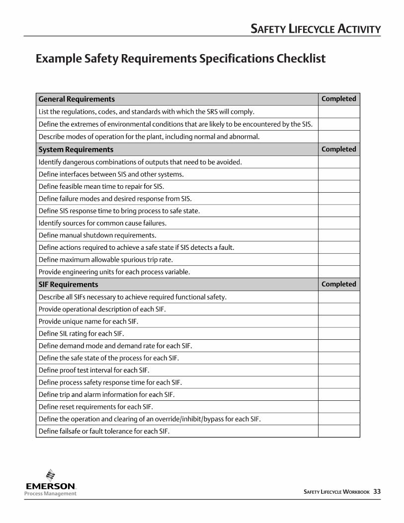
SAFETY LIFECYCLE WORKBOOK 33
Example Safety Requirements Specifications Checklist
SAFETY LIFECYCLE ACTIVITY
34 SAFETY LIFECYCLE WORKBOOK
Implementation Phase
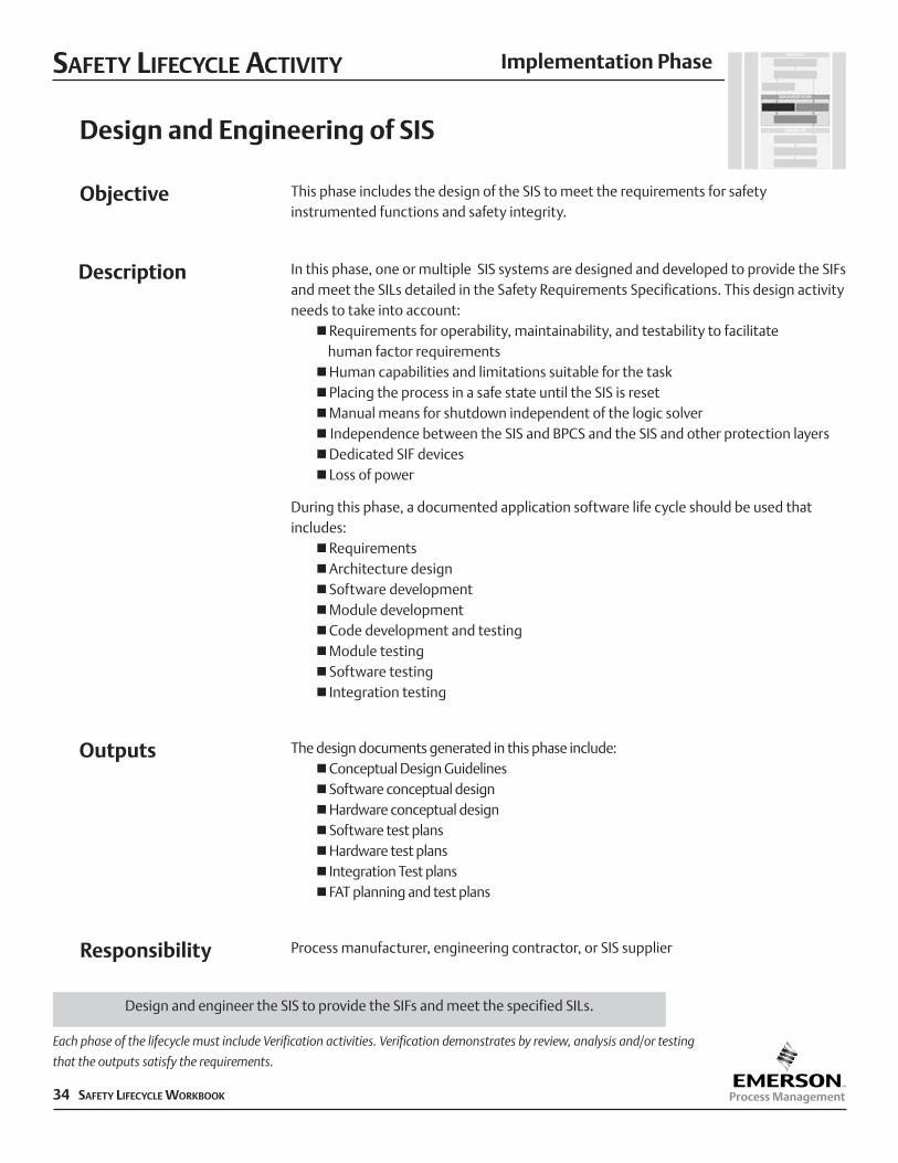
Design and Engineering of SIS
This phase includes the design of the SIS to meet the requirements for safetyinstrumented functions and safety integrity.
In this phase, one or multiple SIS systems are designed and developed to provide the SIFsand meet the SILs detailed in the Safety Requirements Specifications. This design activityneeds to take into account:
nRequirements for operability, maintainability, and testability to facilitate human factor requirements
nHuman capabilities and limitations suitable for the tasknPlacing the process in a safe state until the SIS is resetnManual means for shutdown independent of the logic solvern Independence between the SIS and BPCS and the SIS and other protection layersnDedicated SIF devicesn Loss of power
During this phase, a documented application software life cycle should be used thatincludes:
nRequirementsnArchitecture designnSoftware developmentnModule developmentnCode development and testingnModule testingnSoftware testingn Integration testing
The design documents generated in this phase include:nConceptual Design GuidelinesnSoftware conceptual designnHardware conceptual designnSoftware test plansnHardware test plansn Integration Test plansnFAT planning and test plans
Process manufacturer, engineering contractor, or SIS supplier
Objective
Description
Outputs
Responsibility
Each phase of the lifecycle must include Verification activities. Verification demonstrates by review, analysis and/or testing
that the outputs satisfy the requirements.
Design and engineer the SIS to provide the SIFs and meet the specified SILs.
SAFETY LIFECYCLE ACTIVITY
SAFETY LIFECYCLE WORKBOOK 35
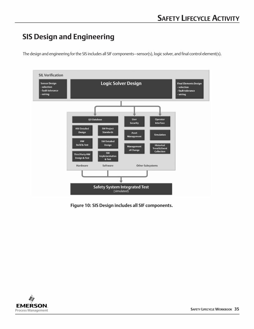
SIS Design and Engineering
Figure 10: SIS Design includes all SIF components.
The design and engineering for the SIS includes all SIF components–sensor(s), logic solver, and final control element(s).
SAFETY LIFECYCLE ACTIVITY
36 SAFETY LIFECYCLE WORKBOOK
Implementation Phase
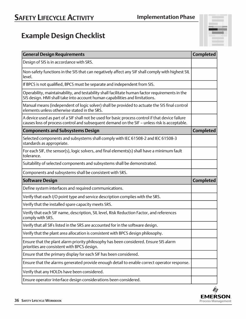
Example Design Checklist
SAFETY LIFECYCLE ACTIVITY
SAFETY LIFECYCLE WORKBOOK 37
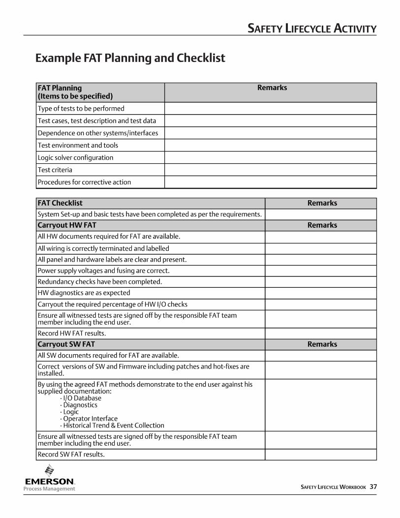
Example FAT Planning and Checklist
SAFETY LIFECYCLE ACTIVITY
38 SAFETY LIFECYCLE WORKBOOK
Implementation Phase
Installation, Commissioning and Validation
This activity ensures that the SIS is installed according to specifications, commissioned toprepare for final system validation, and is validated through inspection and testing thatthe SIS achieves the requirements stated in the SRS.
The installation and commissioning activity should address:nProcedures, measures and techniques to be usednSchedule of activities to take placenPersons and organization responsible for the activities.
The validation activity should include:nValidation of SIS with SRSnValidation of relevant operational modesnProcedures, measures, and techniques to be usednSchedule of activities to take placenPersons and organization responsible for the activitiesnReference information against which validation will be carried out.
Appropriate records that the SIS has been installed properly according to design andinstallation plans.
Appropriate records that the SIS has been commissioned properly.
Appropriate records that the SIS has been validated, including:nSIS validation plan versionnSIF function number test with reference to SRSnTools and equipment used, along with calibration datanResults of each testnTest specification versionnAcceptance criteria for integration testsnSIS hardware and software versions testednDiscrepancy between expected and actual resultsnAnalysis and decisions made based on discrepancy.
Process manufacturer with support from engineering contractor and/or SIS supplier.
Objective
Description
Outputs
Responsibility
Each phase of the lifecycle includes Verification activities. Verification demonstrates by review, analysis and/or testing that
the outputs satisfy the requirements.
Following physical installation and loop testing of the safety related equipment, validation involves the pre-startupverification of the integrated system against the requirements stated in the Safety Requirements Specification.
SAFETY LIFECYCLE ACTIVITY
SAFETY LIFECYCLE WORKBOOK 39
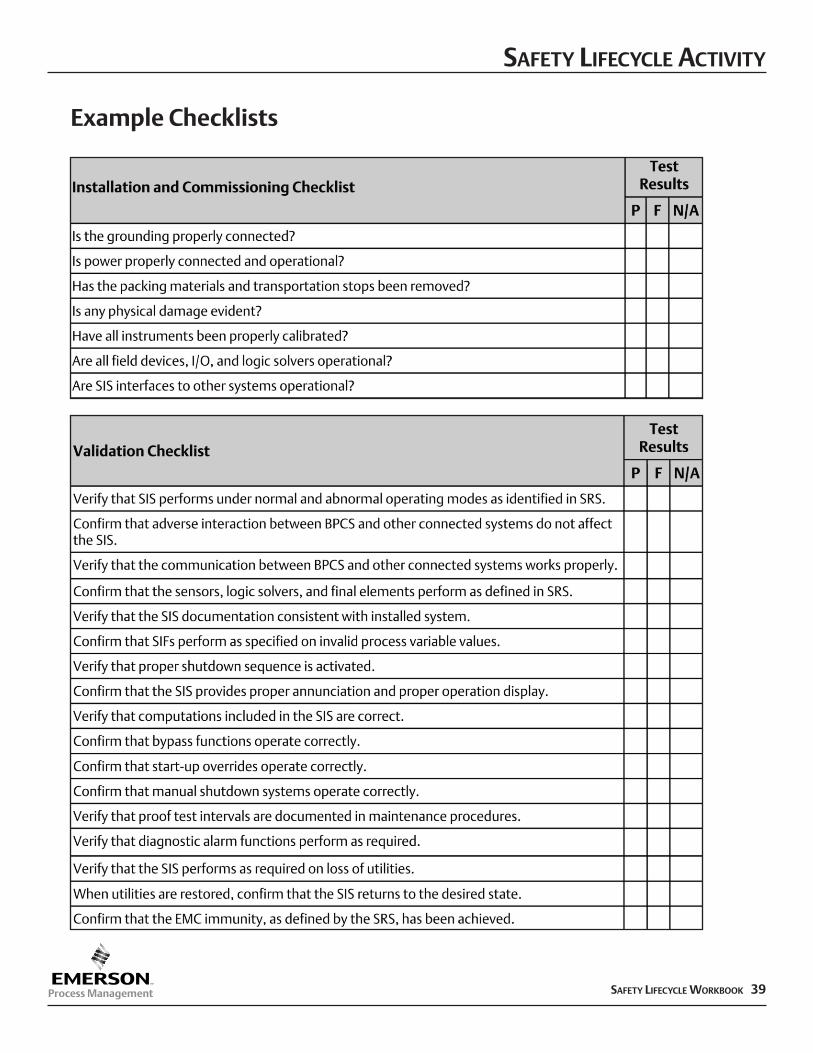
Example Checklists
SAFETY LIFECYCLE ACTIVITY
40 SAFETY LIFECYCLE WORKBOOK
Operation Phase
Operation and Maintenance
The operation and maintenance phase ensures that the required SIL of each SIF ismaintained and the functional safety of the SIS is maintained.
During this phase, the SIS operation and maintenance activities should address:nRoutine and abnormal operationnProof testing, preventive and breakdown maintenancenProcedures, measures and techniques to be usednVerification of adherence to proceduresnSchedule of operation and maintenance activitiesnPersons and organization responsible.
Appropriate records of operation and maintenance activities need to be kept, including:nRoutine actions to maintain functional safetynActions and constraints to prevent an unsafe state or reduce the consequence of a
hazardous eventnSystem failure and demand ratesnSIS audit and test resultsnMaintenance procedures when failures occurnProper calibration of test equipment.
Process manufacturer with support from SIS supplier.
Objective
Description
Outputs
Responsibility
Each phase of the lifecycle includes Verification activities. Verification demonstrates by review, analysis and/or testing that
the outputs satisfy the requirements.
Operation and Maintenance involves procedure based response to system alarms and the performance of periodicfunctional testing of each SIF component to ensure as-designed system operation.
SAFETY LIFECYCLE ACTIVITY
SAFETY LIFECYCLE WORKBOOK 41
Online Testing
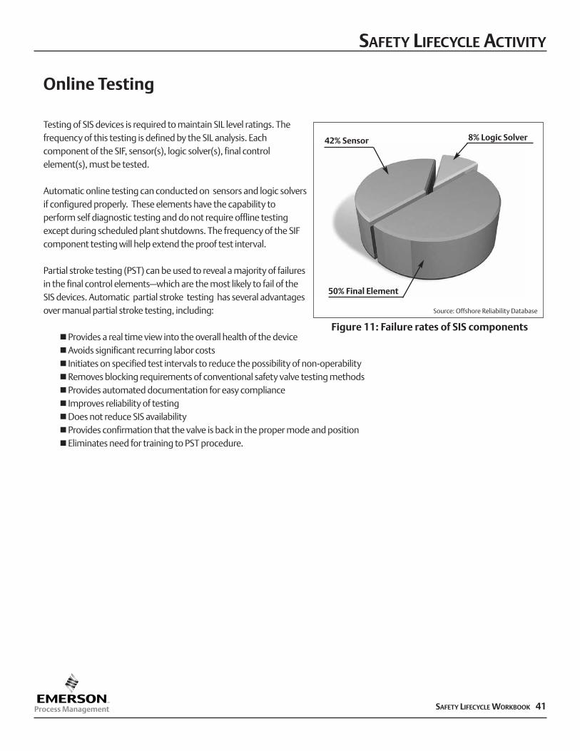
Testing of SIS devices is required to maintain SIL level ratings. Thefrequency of this testing is defined by the SIL analysis. Eachcomponent of the SIF, sensor(s), logic solver(s), final controlelement(s), must be tested.
Automatic online testing can conducted on sensors and logic solversif configured properly. These elements have the capability toperform self diagnostic testing and do not require offline testingexcept during scheduled plant shutdowns. The frequency of the SIFcomponent testing will help extend the proof test interval.
Partial stroke testing (PST) can be used to reveal a majority of failuresin the final control elements–which are the most likely to fail of theSIS devices. Automatic partial stroke testing has several advantagesover manual partial stroke testing, including:
nProvides a real time view into the overall health of the device nAvoids significant recurring labor costsn Initiates on specified test intervals to reduce the possibility of non-operabilitynRemoves blocking requirements of conventional safety valve testing methods nProvides automated documentation for easy compliancen Improves reliability of testingnDoes not reduce SIS availability nProvides confirmation that the valve is back in the proper mode and positionnEliminates need for training to PST procedure.
Figure 11: Failure rates of SIS components
8% Logic Solver
50% Final Element
42% Sensor
Source: Offshore Reliability Database
SAFETY LIFECYCLE ACTIVITY
42 SAFETY LIFECYCLE WORKBOOK
Operation Phase
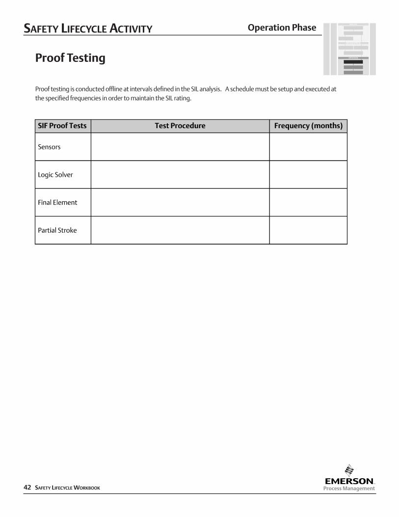
Proof Testing
Proof testing is conducted offline at intervals defined in the SIL analysis. A schedule must be setup and executed atthe specified frequencies in order to maintain the SIL rating.
SAFETY LIFECYCLE ACTIVITY
SAFETY LIFECYCLE WORKBOOK 43
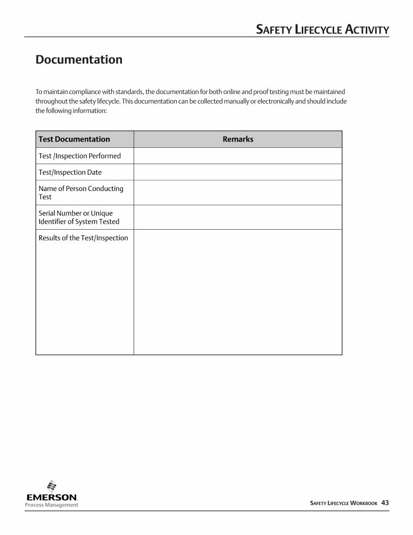
Documentation
To maintain compliance with standards, the documentation for both online and proof testing must be maintainedthroughout the safety lifecycle. This documentation can be collected manually or electronically and should includethe following information:
SAFETY LIFECYCLE ACTIVITY
44 SAFETY LIFECYCLE WORKBOOK
Operation Phase
Modification
This phase ensures that modifications to the SIS are properly planned, reviewed andapproved prior to making the change. Additionally, the required safety integrity level foreach SIF must be maintained despite any changes made to the SIS.
During this phase, it is important that procedures and a documented process forauthoring and controlling changes is in place prior to making changes to the SIS.
Appropriate record of modifications should be kept, including:nDescription of the changenReason for the changen Identified hazardsnAnalysis of the impactnAll required approvalsnTests used to verify that the change was properly implemented and the SIS performs
as requirednConfiguration history/audit trailnTested used to verify that the change has not adversely impacted parts of the SIS that
were not changed.
Process manufacturer
Objective
Description
Outputs
Responsibility
Modifications to the SIS must be properly planned, reviewed, and approved prior to making the change. The requiredsafety integrity level for each SIF must be maintained despite any changes to the SIS.
Each phase of the lifecycle includes Verification activities. Verification demonstrates by review, analysis and/or testing that
the outputs satisfy the requirements.
SAFETY LIFECYCLE ACTIVITY
SAFETY LIFECYCLE WORKBOOK 45
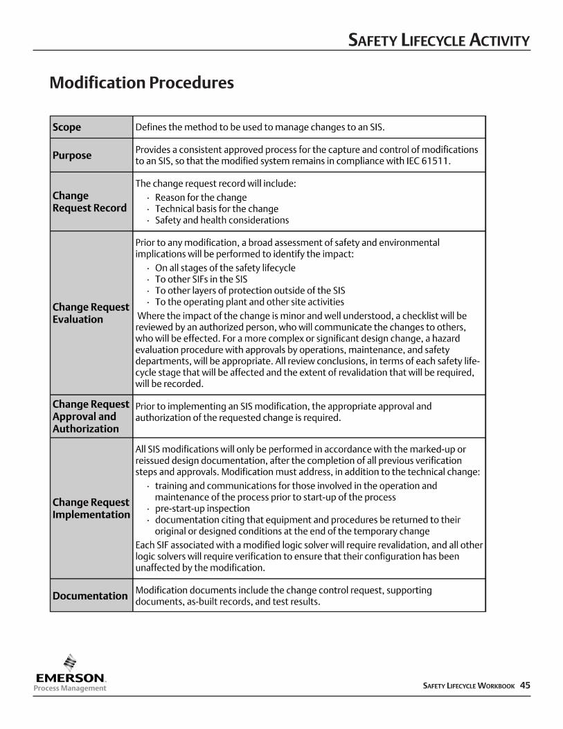
Modification Procedures
SAFETY LIFECYCLE ACTIVITY
46 SAFETY LIFECYCLE WORKBOOK
Operation Phase
Decommissioning
Prior to decommissioning any SIS from active service, a proper review should beconducted with required approvals. During decommissioning activities, required SIFsmust remain operational.
During this phase, procedures for authorizing and controlling changes should remain inplace during decommissioning activities.
Appropriate record of modifications should be kept, including:nProcedures identifying and requesting work to be donen Identifying hazards that may be affectednAnalysis of the impact on functional safety as a result of the proposed
decommissioning activitynResults of the impact analysisnProper authorization before decommissioning.
Process manufacturer
Objective
Description
Outputs
Responsibility
Proper review and approval must be conducted prior to the decommissioning of any SIS from active service.
Each phase of the lifecycle includes Verification activities. Verification demonstrates by review, analysis and/or testing that
the outputs satisfy the requirements.
SAFETY LIFECYCLE ACTIVITY
Management of Change
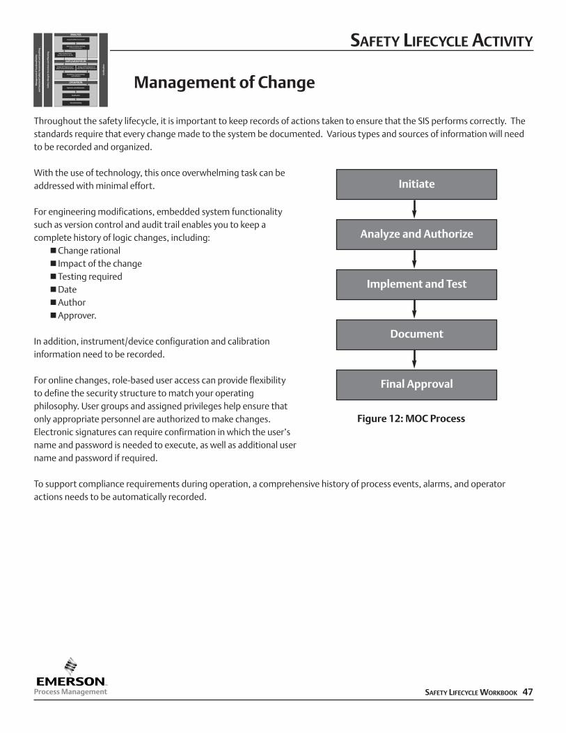
Throughout the safety lifecycle, it is important to keep records of actions taken to ensure that the SIS performs correctly. Thestandards require that every change made to the system be documented. Various types and sources of information will needto be recorded and organized.
With the use of technology, this once overwhelming task can beaddressed with minimal effort.
For engineering modifications, embedded system functionalitysuch as version control and audit trail enables you to keep acomplete history of logic changes, including:
nChange rationaln Impact of the changenTesting requirednDatenAuthornApprover.
In addition, instrument/device configuration and calibrationinformation need to be recorded.
For online changes, role-based user access can provide flexibilityto define the security structure to match your operatingphilosophy. User groups and assigned privileges help ensure thatonly appropriate personnel are authorized to make changes.Electronic signatures can require confirmation in which the user’sname and password is needed to execute, as well as additional user name and password if required.
To support compliance requirements during operation, a comprehensive history of process events, alarms, and operatoractions needs to be automatically recorded.
Initiate
Analyze and Authorize
Implement and Test
Document
Final Approval
SAFETY LIFECYCLE WORKBOOK 47
Figure 12: MOC Process
SAFETY LIFECYCLE ACTIVITY
48 SAFETY LIFECYCLE WORKBOOK
Security
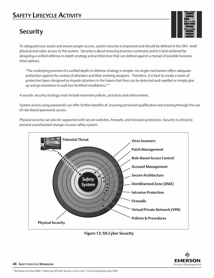
To safeguard your assets and ensure proper access, system security is important and should be defined in the SRS–bothphysical and cyber access to the system. Security is about ensuring business continuity and it is best achieved bydesigning a unified defense-in-depth strategy and architecture that can defend against a myriad of possible businessinterruptions.
“The underlying premise of a unified depth-in-defense strategy is simple–no single mechanism offers adequate protection against the variety of attackers and their evolving weapons. Therefore, it is best to create a series of protection layers designed to impede attackers in the hopes that they can be detected and repelled or simply give up and go elsewhere to seek less fortified installations.”11
A sounds security strategy must include extensive policies, practices and enforcement.
System access using passwords can offer further benefits of ensuring personnel qualification and training through the useof role-based passwords access.
Physical security can also be supported with secure switches, firewalls, and intrusion protection. Security is critical toprevent unauthorized changes to your safety system.
Potential Threat Virus Scanners
Patch Management
Role-Based Access Control
Account Management
Secure Architecture
Demilitarized Zone (DMZ)
Intrusive Protection
Firewalls
Virtual Private Network (VPN)
Policies & ProceduresPhysical Security
11 Bob Huba and Chuck Miller, “Addressing SIS Cyber Security: First or Last?”, Control Engineering, May 2009.
Figure 13: SIS Cyber Security
SUPPLIER QUALIFICATION
Quality cannot be tested into software or products. It must be built in. A process manufacturershould have evidence that a supplier’s products and/or services are high quality. This assurancecan be from:
nCertification of IEC 61508 compliance by a third-party for a safety-related productnPrior-use data that supports the conclusion that the product is safe to use in that applicationnCertification of IEC 61511 compliance by a third-party of a service provider.
To gather further evidence of a vendor’s quality product and/or service, a process manufacturer canevaluate and qualify a supplier’s business and quality practices.
SAFETY LIFECYCLE WORKBOOK 49
Expectations
nFinancial stability–helps ensure that supplier will be in existence to provide future supportnProven experience in the safety industry–provides evidence that the supplier understands your
needsnPrevious business experience–your company’s past project experience with this supplier. Did the
supplier perform to expectations (quality, cost, schedule)?nActive quality programs and standards certification–helps ensure that consistency and quality are
part of the supplier’s processes and culturenFormal documented product development methodology based on IEC 61508 standards–helps
ensure that product development is not dependent on an individual’s creativity, but is a result of aplanned process
nFormal documented application software product development methodology based on IEC61511 standards–helps ensure that application software is not dependent on an individual’screativity, but is a result of a planned process for generating modular, consistent, documented qualityapplication software
nEstablished change control procedures as part of the product development–helps ensure thateach version of product software functions as expected, with proper levels of testing anddocumentation
nDefined personnel qualifications–ensures that properly trained and certified individuals developboth product software and application software
nFactory training and support–supports your compliance efforts during the operation andmaintenance phases of the lifecycle.
Product and Service Certification
Suppliers that provide safety products and/or services to the process industries should be certifiedby a third-party or provide prior-use data to verify compliance with IEC standards.
PRODUCTS:n IEC 61508 certification by third-partynPrior-use data
SERVICES:n IEC 61511 certification by third-partynSafety certified personnel.
SUPPLIER QUALIFICATION
50 SAFETY LIFECYCLE WORKBOOK
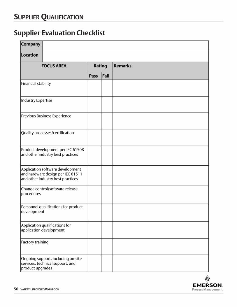
Supplier Evaluation Checklist
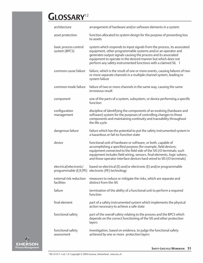
GLOSSARY12
architecture arrangement of hardware and/or software elements in a system
asset protection function allocated to system design for the purpose of preventing loss to assets
basic process control system which responds to input signals from the process, its associatedsystem (BPCS) equipment, other programmable systems and/or an operator and
generates output signals causing the process and its associatedequipment to operate in the desired manner but which does notperform any safety instrumented functions with a claimed SIL�1
common cause failure failure, which is the result of one or more events, causing failures of twoor more separate channels in a multiple channel system, leading tosystem failure
common mode failure failure of two or more channels in the same way, causing the sameerroneous result
component one of the parts of a system, subsystem, or device performing a specificfunction
configuration discipline of identifying the components of an evolving (hardware andmanagement software) system for the purposes of controlling changes to those
components and maintaining continuity and traceability throughoutthe life cycle
dangerous failure failure which has the potential to put the safety instrumented system ina hazardous or fail-to-function state
device functional unit of hardware or software, or both, capable ofaccomplishing a specified purpose (for example, field devices; equipment connected to the field side of the SIS I/O terminals; suchequipment includes field wiring, sensors, final elements, logic solvers,and those operator interface devices hard-wired to SIS I/O terminals)
electrical/electronic/ based on electrical (E) and/or electronic (E) and/or programmableprogrammable (E/E/PE) electronic (PE) technology
external risk reduction measures to reduce or mitigate the risks, which are separate andfacilities distinct from the SIS
failure termination of the ability of a functional unit to perform a required function
final element part of a safety instrumented system which implements the physical action necessary to achieve a safe state
functional safety part of the overall safety relating to the process and the BPCS which depends on the correct functioning of the SIS and other protection layers
functional safety investigation, based on evidence, to judge the functional safety assessment achieved by one or more protection layers
SAFETY LIFECYCLE WORKBOOK 5112IEC 61511-1 ed. 1.0 Copyright © 2003 Geneva, Switzerland. www.iec.ch
functional safety audit systematic and independent examination to determine whether the procedures specificto the functional safety requirements comply with the planned arrangements, areimplemented effectively and are suitable to achieve the specified objectives
hardware safety failures in a dangerous mode of failureintegrity
hazard potential source of harm
impact analysis activity of determining the effect that a change to a function or component will have toother functions or components in that system as well as to other systems
input function function which monitors the process and its associated equipment in order to provideinput information for the logic solver
instrument apparatus used in performing an action (typically found in instrumented systems)
logic function function which performs the transformations between input information (provided byone or more input functions) and output information (used by one or more outputfunctions); logic functions provide the transformation from one or more input functionsto one or more output functions
logic solver that portion of either a BPCS or SIS that performs one or more logic function(s)
mitigation action that reduces the consequence(s) of a hazardous event
mode of operation way in which a safety instrumented function operates
demand mode safety where a specified action (for example, closing of a valve) is taken in response to processinstrumented function conditions or other demands. In the event of a dangerous failure of the safety
instrumented function a potential hazard only occurs in the event of a failure in theprocess or the BPCS
continuous mode where in the event of a dangerous failure of the safety instrumented function a potentialsafety instrumented hazard will occur without further failure unless action is taken to prevent itfunction
MooN safety instrumented system, or part thereof, made up of “N” independent channels,which are so connected, that “M” channels are sufficient to perform the safety instrumented function
necessary risk reduction risk reduction required to ensure that the risk is reduced to a tolerable level
operator interface means by which information is communicated between a human operator(s) and the SIS(for example, CRTs, indicating lights, push-buttons, horns, alarms); the operator interfaceis sometimes referred to as the human-machine interface (HMI)
output function function which controls the process and its associated equipment according to finalactuator information from the logic function
GLOSSARY
52 SAFETY LIFECYCLE WORKBOOK
phase period within the safety life cycle where activities described in this standard take place
prevention action that reduces the frequency of occurrence of a hazardous event
process risk risk arising from the process conditions caused by abnormal events (including BPCSmalfunction)
programmable electronic component or device forming part of a PES and based on computerelectronics (PE) technology. The term encompasses both hardware and software and input and output units
programmable devices, including all elements of the system such as power supplies, sensors and other inputelectronic system (PES) devices, data highways and other communication paths, actuators and other output devices
proof test test performed to reveal undetected faults in a safety instrumented system so that, ifnecessary, the system can be restored to its designed functionality
protection layer any independent mechanism that reduces risk by control, prevention or mitigation
proven-in-use when a documented assessment has shown that there is appropriate evidence, based on the previous use of the component, that the component is suitable for use in a safety instrumented system
quality totality of characteristics of an entity that bear on its ability to satisfy stated and implied needs
random hardware failure failure, occurring at a random time, which results from a variety of degradation mechanismsin the hardware
redundancy use of multiple elements or systems to perform the same function; redundancy can be implemented by identical elements (identical redundancy) or by diverse elements (diverseredundancy)
risk combination of the frequency of occurrence of harm and the severity of that harm
safe failure failure which does not have the potential to put the safety instrumented system in ahazardous or fail-to-function state
safe state state of the process when safety is achieved
safety freedom from unacceptable risk
safety function function to be implemented by an SIS, other technology safety related system or external risk, reduction facilities, which is intended to achieve or maintain a safe state for the process, withrespect to a specific hazardous event
safety instrumented safety function with a specified safety integrity level which is necessary to achieve functionalfunction (SIF) safety and which can be either a safety instrumented protection function or a safety
instrumented control function
safety instrumented instrumented system used to implement one or more safety instrumented functions. An SIS issystem (SIS) composed of any combination of sensor (s), logic solver (s), and final elements(s)
GLOSSARY
SAFETY LIFECYCLE WORKBOOK 53
safety integrity average probability of a safety instrumented system satisfactorily performing the required safety instrumented functions under all the stated conditions within a stated period of time
safety integrity level (SIL) discrete level (one out of four) for specifying the safety integrity requirements of the safety instrumented functions to be allocated to the safety instrumented systems. Safetyintegrity level 4 has the highest level of safety integrity; safety integrity level 1 has the
lowest
safety lifecycle necessary activities involved in the implementation of safety instrumented function(s)occurring during a period of time that starts at the concept phase of a project and finishes when all of the safety instrumented functions are no longer available for use
safety requirements specification that contains all the requirements of the safety instrumented functions thatspecification have to be performed by the safety instrumented systems
sensor device or combination of devices, which measure the process condition (for example, transmitters, transducers, process switches, position switches)
application software software specific to the user application. In general, it contains logic sequences, permissives, limits and expressions that control the appropriate input, output, calculations, decisions necessary to meet the safety instrumented functional requirements. See fixed and limited variability language
software life cycle activities occurring during a period of time that starts when software is conceived and ends when the software is permanently disused
system set of elements, which interact according to a design; an element of a system can be another system, called a subsystem, which may be a controlling system or a controlled system and may include hardware, software and human interaction
systematic failure failure related in a deterministic way to a certain cause, which can only be eliminated by amodification of the design or of the manufacturing process, operational procedures, documentation or other relevant factors
tolerable risk risk which is accepted in a given context based on the current values of societyvalidation activity of demonstrating that the safety instrumented function(s) and safety
instrumented system(s) under consideration after installation meets in all respects the safety requirements specification
verification activity of demonstrating for each phase of the relevant safety life cycle by analysis and/or tests, that, for specific inputs, the outputs meet in all respects the objectives and requirements set for the specific phase
GLOSSARY
54 SAFETY LIFECYCLE WORKBOOK
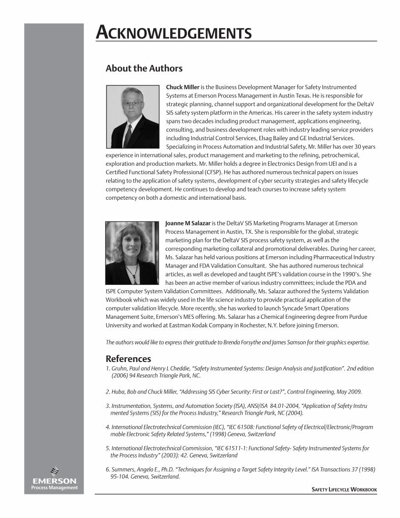
About the Authors
Chuck Miller is the Business Development Manager for Safety InstrumentedSystems at Emerson Process Management in Austin Texas. He is responsible forstrategic planning, channel support and organizational development for the DeltaVSIS safety system platform in the Americas. His career in the safety system industryspans two decades including product management, applications engineering,consulting, and business development roles with industry leading service providersincluding Industrial Control Services, Elsag Bailey and GE Industrial Services.Specializing in Process Automation and Industrial Safety, Mr. Miller has over 30 years
experience in international sales, product management and marketing to the refining, petrochemical,exploration and production markets. Mr. Miller holds a degree in Electronics Design from UEI and is aCertified Functional Safety Professional (CFSP). He has authored numerous technical papers on issuesrelating to the application of safety systems, development of cyber security strategies and safety lifecyclecompetency development. He continues to develop and teach courses to increase safety systemcompetency on both a domestic and international basis.
Joanne M Salazar is the DeltaV SIS Marketing Programs Manager at EmersonProcess Management in Austin, TX. She is responsible for the global, strategicmarketing plan for the DeltaV SIS process safety system, as well as thecorresponding marketing collateral and promotional deliverables. During her career,Ms. Salazar has held various positions at Emerson including Pharmaceutical IndustryManager and FDA Validation Consultant. She has authored numerous technicalarticles, as well as developed and taught ISPE’s validation course in the 1990’s. Shehas been an active member of various industry committees; include the PDA and
ISPE Computer System Validation Committees. Additionally, Ms. Salazar authored the Systems ValidationWorkbook which was widely used in the life science industry to provide practical application of thecomputer validation lifecycle. More recently, she has worked to launch Syncade Smart OperationsManagement Suite, Emerson’s MES offering. Ms. Salazar has a Chemical Engineering degree from PurdueUniversity and worked at Eastman Kodak Company in Rochester, N.Y. before joining Emerson.
The authors would like to express their gratitude to Brenda Forsythe and James Samson for their graphics expertise.
References1. Gruhn, Paul and Henry L Cheddie, “Safety Instrumented Systems: Design Analysis and Justification”. 2nd edition
(2006) 94 Research Triangle Park, NC.
2. Huba, Bob and Chuck Miller, “Addressing SIS Cyber Security: First or Last?”, Control Engineering, May 2009.
3. Instrumentation, Systems, and Automation Society (ISA), ANSI/ISA 84.01-2004, “Application of Safety Instrumented Systems (SIS) for the Process Industry,” Research Triangle Park, NC (2004).
4. International Electrotechnical Commission (IEC), “IEC 61508: Functional Safety of Electrical/Electronic/Programmable Electronic Safety Related Systems,” (1998) Geneva, Switzerland
5. International Electrotechnical Commission, “IEC 61511-1: Functional Safety- Safety Instrumented Systems for the Process Industry” (2003): 42. Geneva, Switzerland
6. Summers, Angela E., Ph.D. “Techniques for Assigning a Target Safety Integrity Level.” ISA Transactions 37 (1998) 95-104. Geneva, Switzerland.
ACKNOWLEDGEMENTS
SAFETY LIFECYCLE WORKBOOK
SAFETY LIFECYCLE WORKBOOKFOR THE PROCESS INDUSTRY SECTOR
This Safety Lifecycle Workbook was developed tohelp business leaders and managers in the processindustries gain a general understanding of existingindustry standards and best practices for SafetyInstrumented Systems (SIS). It also provides apractical overview of the safety lifecycle, includingchecklists and key considerations for each phase.
Form W-0002 / Printed in USA / 2K AQ / 7-10