SafeNet Encryptor, Model 650 for 10 Gigabit Networks · SafeNet Encryptor, Model 650 for 10 Gigabit...
24
© 2010 SafeNet, Inc. All rights reserved. www.safenet-inc.com 002-010004-001 Revision C This document may be freely reproduced and distributed whole and intact including this copyright notice. SafeNet Encryptor, Model 650 for 10 Gigabit Networks FIPS 140-2 – Level 3 Validation Non-Proprietary Security Policy Hardware Part Numbers Note: See Table 2.2-1 for model numbering conventions. with 4.0.2 firmware Security Policy Revision C December 2010 SafeNet SONET Encryptor (SSE ) 904-53260-007 (RoHS) 904-53261-007 (RoHS) SafeNet SONET Encryptor (SSE ) 904-53361-20p (RoHS) SafeNet Ethernet Encryptor (SEE) 943-53270-007 (RoHS) 943-53271-007 (RoHS) SafeNet Ethernet Encryptor (SEE) 943-53371-20p (RoHS)
Transcript of SafeNet Encryptor, Model 650 for 10 Gigabit Networks · SafeNet Encryptor, Model 650 for 10 Gigabit...

© 2010 SafeNet, Inc. All rights reserved. www.safenet-inc.com 002-010004-001 Revision CThis document may be freely reproduced and distributed whole and intact including this copyright notice.
SafeNet Encryptor, Model 650for 10 Gigabit Networks
FIPS 140-2 – Level 3 ValidationNon-Proprietary Security Policy
Hardware Part Numbers
Note: See Table 2.2-1 for model numbering conventions.
with 4.0.2 firmware
Security Policy Revision CDecember 2010
SafeNet SONET Encryptor (SSE ) 904-53260-007 (RoHS) 904-53261-007 (RoHS)
SafeNet SONET Encryptor (SSE ) 904-53361-20p (RoHS)
SafeNet Ethernet Encryptor (SEE) 943-53270-007 (RoHS) 943-53271-007 (RoHS)
SafeNet Ethernet Encryptor (SEE) 943-53371-20p (RoHS)

002-010004-001 Revision C SafeNet Encryptor, Model 650 Security Policy
Page i of ii
TABLE OF CONTENTS
Section Title Page
1 Introduction........................................................................................................................................... 1
1.1 Overview .......................................................................................................................................... 1
1.2 References....................................................................................................................................... 1
1.3 Terminology...................................................................................................................................... 1
1.4 FIPS Requirements.......................................................................................................................... 2
2 SafeNet Encryptor ................................................................................................................................ 3
2.1 Functional Overview......................................................................................................................... 3
2.2 Module Description........................................................................................................................... 42.2.1 Enclosure Indicators Connectors and Controls ......................................................................... 5
2.2.1.1 Front Panel Physical Interfaces....................................................................................................52.2.1.2 Rear Panel Physical Interfaces ....................................................................................................6
2.3 Security Functions............................................................................................................................ 8
2.4 Modes of Operation.......................................................................................................................... 92.4.1 FIPS Approved Mode .............................................................................................................. 102.4.2 Non-FIPS Approved Mode....................................................................................................... 10
2.5 Identification and Authentication .................................................................................................... 102.5.1 Cryptographic Keys and CSPs ................................................................................................ 122.5.2 Roles and Services.................................................................................................................. 142.5.3 Access Control......................................................................................................................... 16
2.6 Physical Security ............................................................................................................................ 17
2.7 Self Tests ....................................................................................................................................... 18
3 Glossary of Acronyms, Terms and Abbreviations .......................................................................... 21

002-010004-001 Revision C SafeNet Encryptor, Model 650 Security Policy
Page ii of ii
LIST OF TABLES
Table Title Page
Table 1.4-1 – Cryptographic Module Security Requirements........................................................................ 2
Table 2.2-1 – Supported Models ................................................................................................................... 4
Table 2.2-2 – Cryptographic Module Logical Interfaces................................................................................ 6
Table 2.2-3 – Mapping of Logical Interfaces to Physical Ports ..................................................................... 7
Table 2.3-1 – Approved Module Algorithms.................................................................................................. 8
Table 2.3-2 – Module Security Functions...................................................................................................... 9
Table 2.5-1 – Roles with Required Identification and Authentication .......................................................... 10
Table 2.5-2 – Strength of Authentication..................................................................................................... 11
Table 2.5-3 Cryptographic Keys and CSPs................................................................................................. 12
Table 2.5-4 Roles and Services .................................................................................................................. 15
Table 2.5-5 Access Control......................................................................................................................... 16
Table 2.6-1 Security Mechanism Inspection and Test ................................................................................ 18
Table 2.7-1 Self Tests ................................................................................................................................. 18
LIST OF FIGURES
Figure Title Page
Figure 2.1-1 – Encryptor Operation............................................................................................................... 3
Figure 2.1-2- Encryptor Usage in Path Encryption Mode.............................................................................. 3
Figure 2.1-3 – Encryptor Usage Example in Line Encryption Mode.............................................................. 4
Figure 2.2-1 – Front View of Model 650 Encryptor........................................................................................ 5
Figure 2.2-2 – Rear View of Model 650 Encryptor ........................................................................................ 5
002-010004-001 Revision C SafeNet Encryptor, Model 650 Security Policy
Page 1 of 21
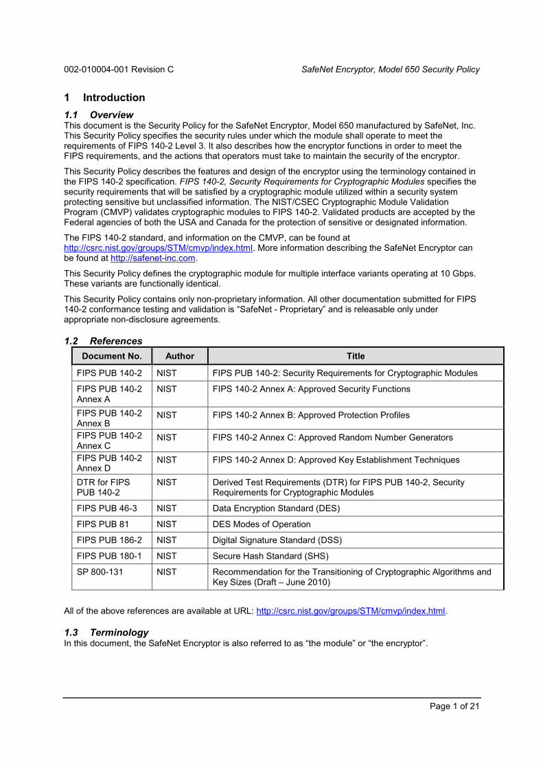
1 Introduction
1.1 OverviewThis document is the Security Policy for the SafeNet Encryptor, Model 650 manufactured by SafeNet, Inc.This Security Policy specifies the security rules under which the module shall operate to meet therequirements of FIPS 140-2 Level 3. It also describes how the encryptor functions in order to meet theFIPS requirements, and the actions that operators must take to maintain the security of the encryptor.
This Security Policy describes the features and design of the encryptor using the terminology contained inthe FIPS 140-2 specification. FIPS 140-2, Security Requirements for Cryptographic Modules specifies thesecurity requirements that will be satisfied by a cryptographic module utilized within a security systemprotecting sensitive but unclassified information. The NIST/CSEC Cryptographic Module ValidationProgram (CMVP) validates cryptographic modules to FIPS 140-2. Validated products are accepted by theFederal agencies of both the USA and Canada for the protection of sensitive or designated information.
The FIPS 140-2 standard, and information on the CMVP, can be found athttp://csrc.nist.gov/groups/STM/cmvp/index.html. More information describing the SafeNet Encryptor canbe found at http://safenet-inc.com.
This Security Policy defines the cryptographic module for multiple interface variants operating at 10 Gbps.These variants are functionally identical.
This Security Policy contains only non-proprietary information. All other documentation submitted for FIPS140-2 conformance testing and validation is “SafeNet - Proprietary” and is releasable only underappropriate non-disclosure agreements.
1.2 References
Document No. Author Title
FIPS PUB 140-2 NIST FIPS PUB 140-2: Security Requirements for Cryptographic Modules
FIPS PUB 140-2Annex A
NIST FIPS 140-2 Annex A: Approved Security Functions
FIPS PUB 140-2Annex B
NIST FIPS 140-2 Annex B: Approved Protection Profiles
FIPS PUB 140-2Annex C
NIST FIPS 140-2 Annex C: Approved Random Number Generators
FIPS PUB 140-2Annex D
NIST FIPS 140-2 Annex D: Approved Key Establishment Techniques
DTR for FIPSPUB 140-2
NIST Derived Test Requirements (DTR) for FIPS PUB 140-2, SecurityRequirements for Cryptographic Modules
FIPS PUB 46-3 NIST Data Encryption Standard (DES)
FIPS PUB 81 NIST DES Modes of Operation
FIPS PUB 186-2 NIST Digital Signature Standard (DSS)
FIPS PUB 180-1 NIST Secure Hash Standard (SHS)
SP 800-131 NIST Recommendation for the Transitioning of Cryptographic Algorithms andKey Sizes (Draft – June 2010)
All of the above references are available at URL: http://csrc.nist.gov/groups/STM/cmvp/index.html.
1.3 TerminologyIn this document, the SafeNet Encryptor is also referred to as “the module” or “the encryptor”.

002-010004-001 Revision C SafeNet Encryptor, Model 650 Security Policy
Page 2 of 21
1.4 FIPS RequirementsThe encryptor meets the overall requirements applicable for FIPS 140-2 Level 3 security as shown inTable 1.4-1.
Table 1.4-1 – Cryptographic Module Security Requirements
Security Requirements Section Level
Cryptographic Module Specification 3
Cryptographic Module Ports and Interfaces 3
Roles and Services and Authentication 3
Finite State Machine Model 3
Physical Security 3
Operational Environment N/A
Cryptographic Key Management 3
EMI/EMC 3
Self-Tests 3
Design Assurance 3
Mitigation of Other Attacks N/A
Cryptographic Module Security Policy 3

002-010004-001 Revision C SafeNet Encryptor, Model 650 Security Policy
Page 3 of 21
2 SafeNet Encryptor
2.1 Functional OverviewThe SafeNet Encryptor provides data privacy and access control for connections between vulnerablepublic and private networks. It employs FIPS-approved AES and Triple-DES algorithms and, with theflexibility to choose the desired interface module, can be deployed in 10 Gigabit SONET or Ethernetnetworks. The encryptor can be centrally controlled or managed across multiple remote stations usingSafeNet's Security Management Center (SMC), a SNMPv3-based security management system.
The role of the encryptor is illustrated in Figure 2.1-1. The encryptor is installed between private networkequipment and a public network. An encryptor communicates with other encryptors in the network,establishing secured connections between itself and the other modules. The encryptors selectivelyencrypt, zeroize, or pass in the clear, data flowing from the switch to the network. Conversely theencryptors selectively decrypt, reject, or pass information flowing from the network to the switch.
Figure 2.1-1 – Encryptor Operation
Secured connections are established between the cryptographic modules using the RSA key exchangeprocess (as specified in the ATM Forum Security Specification version 1.1). This results in a separatesecure session and does not require any secret session keys to ever be displayed or manually transportedand installed.
Figure 2.1-2- Encryptor Usage in Path/Multi-Point Encryption Mode
Figure 2.1-2 shows an example of three secured paths and one unsecured path between sites.

002-010004-001 Revision C SafeNet Encryptor, Model 650 Security Policy
Page 4 of 21
Figure 2.1-3 – Encryptor Usage Example in Line/Link Encryption Mode
SITE 2SITE 1 ENCRYPTOR
ENCRYPTOR
SITE 3ENCRYPTOR
SWITCH/ ADM *
SWITCH/ ADM *
SWITCH/ ADM *
* ADM = Add/Drop Multiplexer
ENCRYPTOR
Figure 2.1-3 shows an example of two secured sessions between sites.
2.2 Module Description
The SafeNet Encryptor is a multiple-chip standalone cryptographic module consisting of production-gradecomponents contained in a physically protected enclosure in accordance with FIPS 140-2 Level 3. Themodule outer casing defines the cryptographic boundary. The steel case completely encloses theencryptor to protect it from tampering. Any attempt to remove the cover will automatically erase allsensitive information stored internally in the encryptor.
Table 2.2-1 – Supported Models
SafeNet SONET Encryptor (SSE ) 904-53260-007 (RoHS) 904-53261-007 (RoHS)
SafeNet SONET Encryptor (SSE ) 904-53361-20p (RoHS)
SafeNet Ethernet Encryptor (SEE) 943-53270-007 (RoHS) 943-53271-007 (RoHS)
SafeNet Ethernet Encryptor (SEE) 943-53371-20p (RoHS)
The ‘p’ in newer model numbers represents thepower variant of the module.
The ‘p’ may be any of the values listed.
1 AC power
7 -48V DC power
Note: The power supplies are outside the cryptographic boundary. While the AC and DC powered casesdiffer slightly to accommodate the different style power supplies, both case styles are designed to preventtampering or probing of the internal components even when the power supplies are removed.
The principle difference between the models is the enclosed line interface card containing the protocolspecific cryptographic accelerators. The line interface card itself is not meant to be field serviceable. Anyattempt to remove the interface will tamper the encryptor, erasing all sensitive information storedinternally. While the line interface cards are not field-serviceable, the pluggable transceivers are. Thepluggable transceivers are outside the cryptographic boundary and may be changed as needed for thespecific requirements of the network infrastructure.
Module management is provided in-band or out-of-band. In-band management uses managementchannels on the module’s interface ports. Out-of-band management is provided using the dedicatedEthernet port or a console port.

002-010004-001 Revision C SafeNet Encryptor, Model 650 Security Policy
Page 5 of 21
2.2.1 Enclosure Indicators Connectors and Controls
The 650 series models share a common enclosure. Figure 2.2-1 shows the front view, which is themechanically for all the 650 series models. The front panel provides a network management port, aconsole port, a USB port, an LCD display and LEDs for status, and a keypad for control input.
Figure 2.2-1 – Front View of Model 650 Encryptor
Figure 2.2-2 – Rear View of Model 650 Encryptor
The encryptor has two network interfaces located in the rear of the module (Figure 2.2-2): the Local Portinterface connects to a physically secure private network and the Network Port interface connects to anunsecure public network. The rear view is identical for the models except for the labeling on the lineinterface card. The labeling identifies interface card as SONET or Ethernet.
The rear panel also contains network activity LEDs as well as status LEDs on the power supply units (DCvariant shown). The height accommodates the dual power supplies. A tamper evident seal indicatesmovement of the module cover with respect to the module enclosure.
2.2.1.1 Front Panel Physical Interfaces
The RJ45 Ethernet port allows remote management from the SMC application. Access is protected bySNMPv3 security mechanisms for authentication and data encryption.
RJ45 –remote management
RS-232local terminal
USB -reserved
LCD display
LEDs –system state /network traffic
Keypad
LEDs –system state /network traffic
Network port(public network)
Local port(private network)
Tamper evidentseal
Powerconnectors

002-010004-001 Revision C SafeNet Encryptor, Model 650 Security Policy
Page 6 of 21
The DB9 RS-232 serial console port connects to a local terminal and provides a command lineinterface for initialization prior to authentication and operation in the approved mode. This port alsoallows administrative access and monitoring of operations. Access is protected by user names andpasswords.
The USB port is reserved for future use.
The keypad allows entry of initialization commands.
The LCD displays configuration information in response to commands entered using the front panelkeypad and indicates the state of RSA keys and certificates.
The LEDs indicate the state of the system including alarms.
2.2.1.2 Rear Panel Physical Interfaces
The LEDs indicate network traffic.
The power connectors are used for power input to the module.
The Network Port connects to the public network via the transceiver’s rear panel public networkconnector. Access is protected by RSA certificates. The Local Port and Network Port are of the sameinterface type.
The Local Port connects to the private network via the transceiver’s rear panel local networkconnector. The Local Port and Network Port are of the same interface type.
The logical interfaces consist of Data Input, Data Output, Control Input, and Status Output as follows:
Table 2.2-2 – Cryptographic Module Logical Interfaces
LogicalInterface
Description
Data InputData Output
Local Port:
Connects to the private network via the transceiver, sending and receivingplaintext user data.
Network Port:
Connects to the public network via the transceiver, sending and receivingciphertext and plaintext user data to and from a far end module.
Sends authentication data and RSA key exchange components to a far endmodule.
Receives authentication data, RSA key exchange components from a far endmodule.
The module can be set to bypass, to send and receive plaintext for the selectedconnection.

002-010004-001 Revision C SafeNet Encryptor, Model 650 Security Policy
Page 7 of 21
LogicalInterface
Description
Control Input Control Input is provided by the front panel keypad, the serial port, the Ethernet Port(out-of-band control), and the Local and Network ports (in-band control) as follows:
The front panel keypad is used for initialization prior to authentication andoperation in the approved mode. An operator uses the keypad to set the IPaddress for remote administration by SMC, set the system clock and load thecertificate (in conjunction with the SMC).
The front panel DB9 RS-232 serial console port may be used for initialization priorto authentication and operation in the approved mode as an alternative to usingthe keypad. This port receives control input (protected via a username andpassword) from a locally connected terminal.
The front panel RJ45 Ethernet port receives out-of-band control input from theSMC application.
Local and Network ports may receive in-band control input, protected via theSNMPv3 security mechanisms, from the SMC application.
Status output Status output is provided by the LCD, front and rear panel LEDs, the Front Panel DB9RS-232 port, the Ethernet Port (out-of-band status), and the Local and Network ports(in-band status) as follows:
The LCD indicates the state of RSA keys and certificates and displays commanddata being entered using the front panel keypad.
Front and rear panel LEDs indicate error states, state of the local and networkinterfaces, alarm, temperature, and battery state.
The front panel DB9 RS-232 serial console port may be used for initialization priorto authentication and operation in the approved mode as an alternative to usingthe keypad. It is also used for monitoring some operations. This port sends statusoutput (protected via a username and password) to a locally connected terminal.
The front panel RJ45 Ethernet port sends out-of-band status output information toan SMC application.
Local and Network ports may send in-band status output information, protectedvia the SNMPv3 security mechanisms, to the SMC application.
Table 2.2-3 maps FIPS 140-2 logical interfaces to the cryptographic module’s logical interfaces andphysical ports.
Table 2.2-3 – Mapping of Logical Interfaces to Physical Ports
FIPS 140-2 LogicalInterface
Logical Interface Physical Port
Data Input 1) Public network interface
2) Private network interface
1) Rear panel Network Port
2) Rear panel Local Port
Data Output 1) Public network interface
2) Private network interface
1) Rear panel Network Port
2) Rear panel Local Port
Control Input 1) SNMPv3 interface
2) Local console
3) Keypad
4) Public network interface
1) Front panel RJ45 Ethernet port
2) Front panel DB9 RS-232 serial console port
3) Front panel Keypad/Display
4) Rear panel Network Port
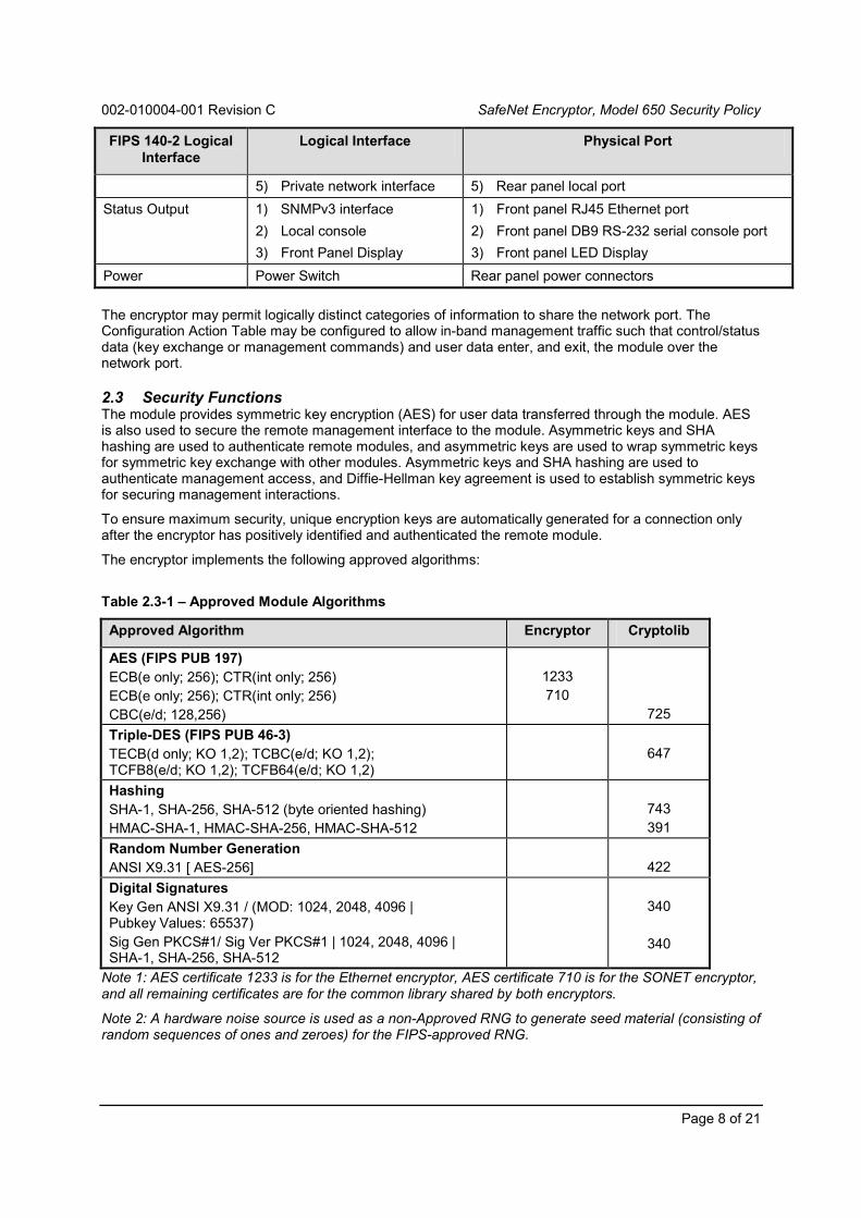
002-010004-001 Revision C SafeNet Encryptor, Model 650 Security Policy
Page 8 of 21
FIPS 140-2 LogicalInterface
Logical Interface Physical Port
5) Private network interface 5) Rear panel local port
Status Output 1) SNMPv3 interface
2) Local console
3) Front Panel Display
1) Front panel RJ45 Ethernet port
2) Front panel DB9 RS-232 serial console port
3) Front panel LED Display
Power Power Switch Rear panel power connectors
The encryptor may permit logically distinct categories of information to share the network port. TheConfiguration Action Table may be configured to allow in-band management traffic such that control/statusdata (key exchange or management commands) and user data enter, and exit, the module over thenetwork port.
2.3 Security FunctionsThe module provides symmetric key encryption (AES) for user data transferred through the module. AESis also used to secure the remote management interface to the module. Asymmetric keys and SHAhashing are used to authenticate remote modules, and asymmetric keys are used to wrap symmetric keysfor symmetric key exchange with other modules. Asymmetric keys and SHA hashing are used toauthenticate management access, and Diffie-Hellman key agreement is used to establish symmetric keysfor securing management interactions.
To ensure maximum security, unique encryption keys are automatically generated for a connection onlyafter the encryptor has positively identified and authenticated the remote module.
The encryptor implements the following approved algorithms:
Table 2.3-1 – Approved Module Algorithms
Approved Algorithm Encryptor Cryptolib
AES (FIPS PUB 197)
ECB(e only; 256); CTR(int only; 256)
ECB(e only; 256); CTR(int only; 256)
CBC(e/d; 128,256)
1233
710
725
Triple-DES (FIPS PUB 46-3)
TECB(d only; KO 1,2); TCBC(e/d; KO 1,2);TCFB8(e/d; KO 1,2); TCFB64(e/d; KO 1,2)
647
Hashing
SHA-1, SHA-256, SHA-512 (byte oriented hashing)
HMAC-SHA-1, HMAC-SHA-256, HMAC-SHA-512
743
391
Random Number Generation
ANSI X9.31 [ AES-256] 422
Digital Signatures
Key Gen ANSI X9.31 / (MOD: 1024, 2048, 4096 |Pubkey Values: 65537)
Sig Gen PKCS#1/ Sig Ver PKCS#1 | 1024, 2048, 4096 |SHA-1, SHA-256, SHA-512
340
340
Note 1: AES certificate 1233 is for the Ethernet encryptor, AES certificate 710 is for the SONET encryptor,and all remaining certificates are for the common library shared by both encryptors.
Note 2: A hardware noise source is used as a non-Approved RNG to generate seed material (consisting ofrandom sequences of ones and zeroes) for the FIPS-approved RNG.

002-010004-001 Revision C SafeNet Encryptor, Model 650 Security Policy
Page 9 of 21
The encryptor implements the following security functions:
Table 2.3-2 – Module Security Functions
Security Function
Symmetric Key Encryption
AES
Triple-DES
Symmetric Key Establishment(See Note below this table)
RSA key establishment (per ATM Forum Security Spec 1.1)
Diffie-Hellman key agreement
Public Key Length: 1024 bitsPrivate Key Length: 1023 bits
Authentication
RSA asymmetric key1024-bit (per ANSI X9.31) with HMAC SHA-12048-bit (per ANSI X9.31) with HMAC SHA-256
Key Generation
Triple-DES/AES Keys – PRNG (per ANSI X9.31)
RSA keys – ANSI X9.31
Note – Key establishment methodology provides a minimum of 80-bits of encryption strength.
2.4 Modes of OperationThe module is shipped by the manufacturer with the FIPS approved mode of operation enabled.
Each encryptor must have a unique Network Certificate (NC) issued under a common SecurityManagement Center (SMC). During key exchange, communicating modules mutually authenticate oneanother by exchanging NCs in digitally-signed messages. The module cannot build a secure connectionwith a remote module that does not have a valid NC. Moreover, the module cannot establish anyconnections unless it has been issued a valid NC. This mode of operation requires a common SMC toissue NCs to all modules that will communicate securely. For backward interoperability, the modulesupports 1024-bit as well as 2048-bit Network Certificates. When establishing secure connections, themodule will default to the 2048-bit certificate and SHA-256 hashing if a 2048-bit certificate is available. Ifthere is no 2048-bit certificate, the module will fall back to the 1024-bit certificate and SHA-1 hashingestablishing secure connections.
User data received from the local (private) network is encrypted before being transmitted out to the publicnetwork. Similarly, user data received from the public network is decrypted before being transmitted to thelocal network. When a secure connection is first created, the pair of encryptors exchange an encryptionmaster key and session key. The master key is used for all subsequent session key exchanges. Whenoperating in this state, the two ends of the connection are in cryptographic synchronization using thedefined AES algorithm. Crypto officers can force a new master key by manually restarting a connection.An organization’s security policy dictates the frequency of forcing a new master key. Within a secureconnection, the module encrypts all data received from the Local Port (the private network) and decryptsall data received from the Network Port (the public network). For each connection, the Connection ActionTable can be set to encrypt, block, or pass data. The module supports configured encryption, blocking, orpassing of user data as plaintext on a per-connection basis.
The FIPS mode status may be queried from the management application or the console interface, andoperators may run the power-on self-tests on-demand by power-cycling the module. Refer to the User’sGuide for more details concerning the module’s modes of operation.

002-010004-001 Revision C SafeNet Encryptor, Model 650 Security Policy
Page 10 of 21
2.4.1 FIPS Approved Mode
The module ships with FIPS Mode enabled. FIPS Mode constrains several aspects of the module’soperation:
The privacy of the SNMPv3-based management interface is ensured with AES encryption; theprivacy option can not be disabled while in FIPS mode.
All the algorithms accessible to the module are approved algorithms as noted above. Non-approved algorithms cannot be specified for use.
The FIPS mode of operation can be confirmed by logging into the console interface and using the fipscommand. It can also be confirmed by reviewing the device configuration from SMC. The module frontpanel SEC LED provides details about the operational configuration of the device, as detailed in the User’sGuide, but does not specifically indicate the FIPS Mode status of the module.
FIPS Mode operation may be turned off as needed. When FIPS Mode operation is turned off, theSNMPv3 Privacy option may also be disabled; however, to turn FIPS Mode operation back on, SNMPv3Privacy must first be re-enabled.
When changing from FIPS Mode to non-FIPS Mode operation, a module erase and reboot is forced. Thiseffectively zeroizes all keys and CSPs prior to the transition.
2.4.2 Non-FIPS Approved Mode
Non-FIPS Mode operations follow the same general flow as FIPS Mode. The module must be certified;connections must be configured; the encryptors must authenticate to each other with NCs. When themodule is set by a Crypto Officer to operate in non-FIPS approved mode, several aspects of the module’soperation are relaxed:
The SNMPv3-based management interface need not be encrypted; the SNMPv3 privacy featuremay be disabled or enabled as needed.
The module may employ non-approved algorithms.
While SNMPv3 privacy may be disabled when FIPS Mode operation is turned off, the SNMPv3 Privacymust first be re-enabled before FIPS Mode operation can be turned back on. The non-approvedalgorithms are disabled within the module automatically, but FIPS Mode cannot be set if SNMPv3 privacyis disabled.
When changing from non-FIPS Mode to FIPS Mode operation, a module erase and reboot is forced. Thiseffectively zeroizes all keys and CSPs prior to the transition.
2.5 Identification and AuthenticationThe module supports two Crypto Officer roles and a single Network User role. Services for the CryptoOfficer roles (full access and read only) are accessible directly via the console or remotely via the SMCapplication. The Network User role services are only accessible indirectly based on the configuredconnections with other cryptographic modules. Roles cannot be changed while authenticated to themodule.
Access to the authorized roles is restricted as follows in Table 2.5-1:
Table 2.5-1 – Roles with Required Identification and Authentication
Role Type ofAuthentication
Authentication Data
Crypto Officer (FullAccess)
Identity-based Crypto Officers using the CLI present unique usernames and passwords to log in to the CLI.
Crypto Officers using SMC present unique identities(embedded in the SNMPv3 command protocol).

002-010004-001 Revision C SafeNet Encryptor, Model 650 Security Policy
Page 11 of 21
Role Type ofAuthentication
Authentication Data
Crypto Officer(Read Only)
Identity-based Crypto Officers using the CLI present unique usernames and passwords to log in to the CLI.
Crypto Officers using SMC present unique identities(embedded in the SNMPv3 command protocol).
Network User Identity-based Network Users (remote Encryptors) must present acertificate issued by the SMC.
Multiple concurrent Crypto Officers and Network Users are allowed. For example, a Network User may besending data to the data input port while a Crypto Officer is connected via the console or sending anSNMPv3 command to the module. The architecture of the system allows for simultaneous interactionswith many far end systems, or Network Users. Access control rules, system timing, and internal controlsmaintain separation of multiple concurrent Crypto Officers and Network Users.
The module employs identity-based authentication of operators and users. Up to 30 unique names andpasswords can be defined for operators of the module.
Crypto Officers using the console enter their name and password to authenticate directly with themodule.
Crypto Officers using SMC to issue SNMPv3 commands to the Encryptor, use SNMPv3-basedauthentication to establish a secure connection / tunnel to the module. Within the secure tunnel,SNMPv3 commands are individually authenticated to ensure Data Origin Authentication, and DataIntegrity for all commands sent from SMC. Data Origin Authentication, based on the above names andpasswords, ensures the authenticity of the identity of the user claiming to have sent the command.
Users (Network Users) using the module cryptographic algorithms and security functions over theData Input and Output ports authenticate using certificates that have been generated and signed bythe SMC. These Network Users exchange master and session keys using RSA public key certificatesthat have been generated and signed by a common SMC.
Physical Maintenance is performed at the factory, as there are no services that require the cover to beremoved in the field. The module should be zeroized by a Crypto Officer before the module is returned tothe factory, either by command or by removing the network interface card.
The strength of the authentication, per the above roles, is as follows:
Table 2.5-2 – Strength of Authentication.
Authentication Mechanism Strength of Mechanism

002-010004-001 Revision C SafeNet Encryptor, Model 650 Security Policy
Page 12 of 21
Authentication Mechanism Strength of Mechanism
Authentication Password Crypto Officers accessing the module using the CLI (via theconsole port) must authenticate using a password that is at least 8characters and at most 30 characters. The characters used in thepassword must be from the ASCII character set of alphanumericand special (shift-number) characters.
This yields a minimum of 628
(over 218 trillion) possiblecombinations (8 characters, 62 possibilities per character);thus, the possibility of correctly guessing a password is lessthan 1 in 1,000,000.
After three failed authentication attempts via the CLI, consoleport access is locked for 3 minutes; thus, the possibility ofrandomly guessing a password in 60 seconds is less than 1 in100,000.
Note: the module suppresses feedback of authentication databeing entered into the CLI by returning blank characters.
Authentication from SMC Authentication with SMC is accomplished via SNMPv3 and theAuthentication Password described above.
Based on the noted characteristics of the password, thepossibility of correctly guessing the authentication data is lessthan 1 in 1,000,000.
The multi-step handshaking process for establishing aconnection and then issuing an authenticated command setsthe possibility of randomly guessing the passphrase in 60seconds at less than 1 in 100,000.
Network User Certificates Network Users must authenticate using a 1024-bit or 2048-bit RSAauthentication certificate based on a key of similar size.
The possibility of deriving a private RSA key is less than 1 in1,000,000 and the possibility of randomly guessing the key in60 seconds is less than 1 in 100,000.
The multi-step handshaking process for establishing aconnection sets the possibility of randomly guessing theauthentication data in 60 seconds at less than 1 in 100,000.
2.5.1 Cryptographic Keys and CSPs
Table 2.5-3 identifies the Cryptographic Keys and Critical Security Parameters (CSPs) employed withinthe module.
Table 2.5-3 Cryptographic Keys and CSPs
Data Item Description
System Master Key On initialization, the module generates a 168-bit symmetric key that isstored in the clear in battery-backed RAM.
This key encrypts (using 3-key Triple-DES CFB8) the module’spublic and private RSA keys and the user table stored in theconfiguration flash memory.
On tamper, the module zeroizes the System Master Key (SMK),rendering the encrypted data in the flash memory undecipherable.

002-010004-001 Revision C SafeNet Encryptor, Model 650 Security Policy
Page 13 of 21
Data Item Description
RSA Private Key The secret component of the module’s RSA Key pair.
This 1024-bit or 2048-bit key is generated when the modulereceives a load certificate command from the SMC, and is used toauthenticate connections with other encryptors and to unwrapmaster session keys and session keys received from far-endencryptors.
This key is stored encrypted in flash memory.
On tamper, the SMK is zeroized, rendering the encrypted privatekey undecipherable.
RSA Public Key The public component of the module’s RSA Key pair is storedencrypted in flash memory.
This key resides in the Network Certificate that in turn is stored inthe clear in system non-volatile RAM.
This key is used for authenticating connections with otherencryptors.
Authentication Password Up to 30 passwords (and associated usernames) may be stored toallow access by up to 30 unique operators in the role of Crypto Officer(full access) or Crypto Officer (read only).
The CLI uses the authentication password to authenticate CryptoOfficers accessing the system via the console port.
SNMPv3 concatenates and hashes (with SHA-1) theauthentication password (8-30 characters) and the SNMPv3unique engine ID to create an HMAC key used for Data OriginAuthentication, and Data Integrity of each command.
Passwords and usernames are hashed and stored in theencrypted user table in flash memory.
On tamper, the SMK is zeroized, rendering the encryptedpasswords undecipherable.
Management Privacy Key The Management Privacy Key (MPK) is the parameter that is used tosecure data on the remote management channel. This parameter isessentially a key that is derived from a DH key exchange between themodule and the remote management station.
The MPK persists for the life of the management session and isused to AES encrypt management traffic that may be exchangedbetween the module and the remote management station.
The MPK is maintained in volatile memory and may be updatedperiodically during the session.
The MPK is destroyed at the end of a session.
Master Session Key For each session, the module generates a symmetric Master SessionKey (MSK) and Session Keys using the ANSI X9.31 PRNG.
The MSK is used with RSA key exchange to transfer these keys toa far-end encryptor for data encryption and decryption purposes.
The MSK persists for the life of the session and is used to AES-encrypt session keys that may be changed periodically during thesession.
All session keys are destroyed at the end of its session.

002-010004-001 Revision C SafeNet Encryptor, Model 650 Security Policy
Page 14 of 21
Data Item Description
Session Keys For each session the module generates two Session Keys (SKs) foreach data flow path in a secure connection (one for the Initiator-Responder path and another for the Responder-Initiator path).
These keys are used to AES-encrypt user data transferredbetween encryptors.
SKs may be changed periodically during the session based ontime or based on the amount of data transferred.
All SKs are destroyed at the end of a session.
Network Certificate The Network Certificate (NC) is the X.509v3 certificate associated withthe module in an operational environment.
The NC is produced and signed by the managing SMC system,then stored in the clear in the module’s non-volatile system RAMand used for authenticating connections with other encryptors.
Other encryptors use the public key embedded in the NC to wrapinitial SKs used to encrypt a session with AES.
The NC is deleted from memory only on an Erase command froma module operator or a tamper condition.
PRNG Seed Key A new X9.31 PRNG Seed Key is generated from a block of 160 bitsoutput by the hardware noise source.
The Seed Key is not stored and is never output from the module. Itexists temporarily in volatile memory and is zeroized by powercycling the module.
PRNG Seed Value A new X9.31 PRNG Seed Value is generated from a block of 160 bitsoutput by the hardware noise source.
The Seed Value is not stored and is never output from the module.It exists temporarily in volatile memory and is zeroized by powercycling the module.
Note: While the above table lists the certificates maintained within the module, the certificates contain onlypublic information.
The module prevents data output during initialization and self test.
No data is output from the module until the self tests complete successfully and the NC has beenproperly loaded into the module.
No data is output during and after zeroization of cryptographic keys and CSPs as this occurs when atamper condition exists.
The encryptor’s internal modules and timing controls work together to isolate user data input andoutput processes from CSP and key management functions.
2.5.2 Roles and Services
The encryptor supports services that are available to Crypto Officers and Users. All of the services aredescribed in detail in the module’s User’s Guide and in the SMC User’s Guide.
The Crypto Officer (full access) role provides cryptographic initialization and management functions.Crypto Officer functions are available using SMC and via the console CLI.
The Crypto Officer (read only) role is restricted to read-only access to module configuration data.
The Network User Role can negotiate encryption/decryption keys and use encryption/decryption services.(The Network User Role is available only to, or in conjunction with, other authenticated modules.)

002-010004-001 Revision C SafeNet Encryptor, Model 650 Security Policy
Page 15 of 21
Table 2.5-4 shows the services available to the various roles. All services except Run Self Test (PowerCycle the Module), AES or Triple-DES encryption, SHA-1hashing for password verification, and physicaltamper, require a console operator to be authenticated by entering a username and password, or an SMCoperator to use RSA public key authentication and SNMPv3 user authentication.
Table 2.5-4 Roles and Services
Service No Role
CryptoOfficer
(FullAccess)
CryptoOfficer(ReadOnly)
NetworkUser
Load Initial Network Certificate ● Load Subsequent Network Certificate ● Set Real Time Clock ● Edit Connection Action Table ● View Connection Action Table ● ● Create user accounts ● Modify user accounts ● Delete user accounts ● Show Software Version ● ● View User Accounts ● ● Clear Audit Trail ● View Audit Trail ● ● Clear Event Log ● View Event Log ● ● View FIPS Mode Status ● ● Change SNMPv3 Privacy Mode ●[4]
Run Self Test (Power Cycle the Module) ● Run Self Test (Reboot Command) ●Generate AES session keys ●[1] ● Generate Initialization Vector ●[1] ● Agree on management privacy key ●[5] ●[5]
RSA signature generation ●[1] ● RSA signature verification ●[1] ● AES encryption ●[2],[5] ●[5] ●
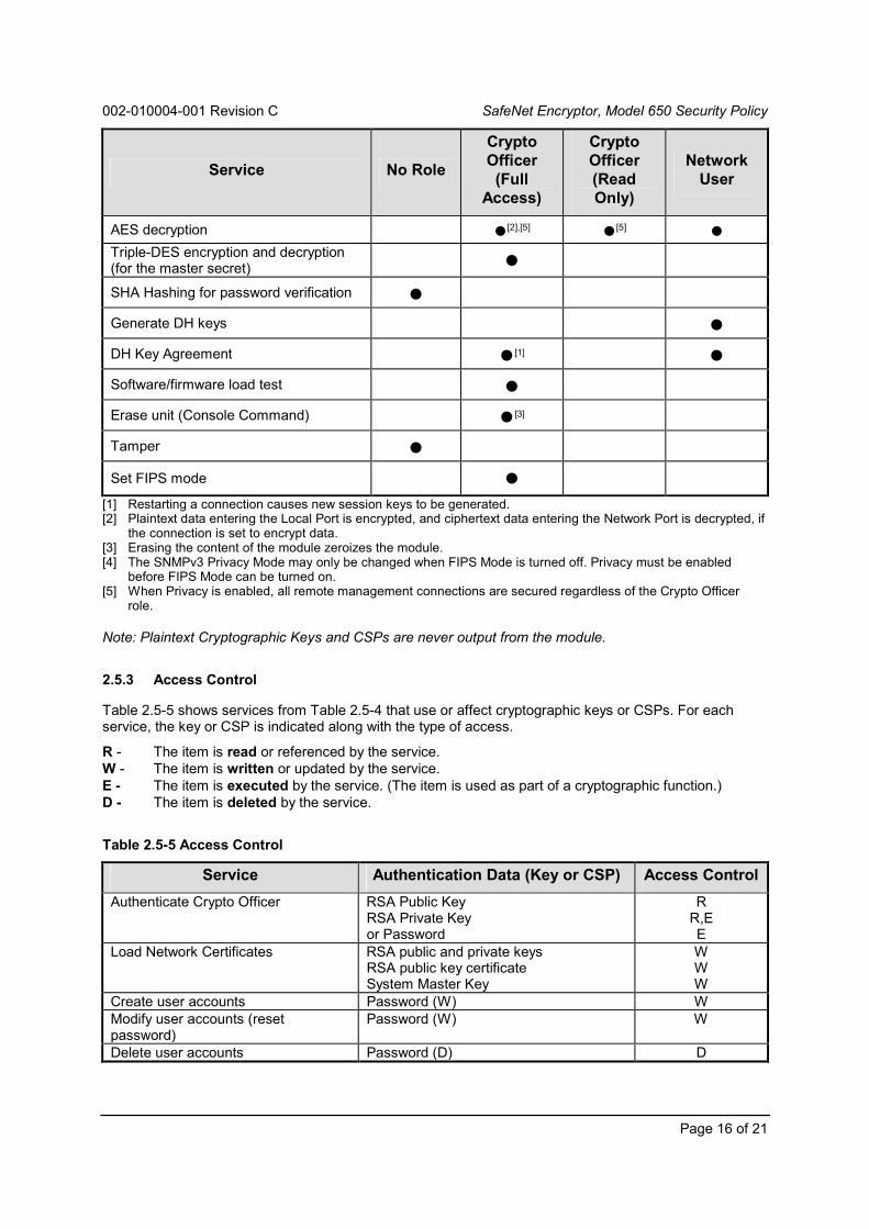
002-010004-001 Revision C SafeNet Encryptor, Model 650 Security Policy
Page 16 of 21
Service No Role
CryptoOfficer
(FullAccess)
CryptoOfficer(ReadOnly)
NetworkUser
AES decryption ●[2],[5] ●[5] ●Triple-DES encryption and decryption(for the master secret) ● SHA Hashing for password verification ● Generate DH keys ● DH Key Agreement ●[1] ● Software/firmware load test ● Erase unit (Console Command) ●[3]
Tamper ● Set FIPS mode ●
[1] Restarting a connection causes new session keys to be generated.[2] Plaintext data entering the Local Port is encrypted, and ciphertext data entering the Network Port is decrypted, if
the connection is set to encrypt data.[3] Erasing the content of the module zeroizes the module.[4] The SNMPv3 Privacy Mode may only be changed when FIPS Mode is turned off. Privacy must be enabled
before FIPS Mode can be turned on.[5] When Privacy is enabled, all remote management connections are secured regardless of the Crypto Officer
role.
Note: Plaintext Cryptographic Keys and CSPs are never output from the module.
2.5.3 Access Control
Table 2.5-5 shows services from Table 2.5-4 that use or affect cryptographic keys or CSPs. For eachservice, the key or CSP is indicated along with the type of access.
R - The item is read or referenced by the service.W - The item is written or updated by the service.E - The item is executed by the service. (The item is used as part of a cryptographic function.)D - The item is deleted by the service.
Table 2.5-5 Access Control
Service Authentication Data (Key or CSP) Access Control
Authenticate Crypto Officer RSA Public KeyRSA Private Keyor Password
RR,EE
Load Network Certificates RSA public and private keysRSA public key certificateSystem Master Key
WWW
Create user accounts Password (W) WModify user accounts (resetpassword)
Password (W) W
Delete user accounts Password (D) D
002-010004-001 Revision C SafeNet Encryptor, Model 650 Security Policy
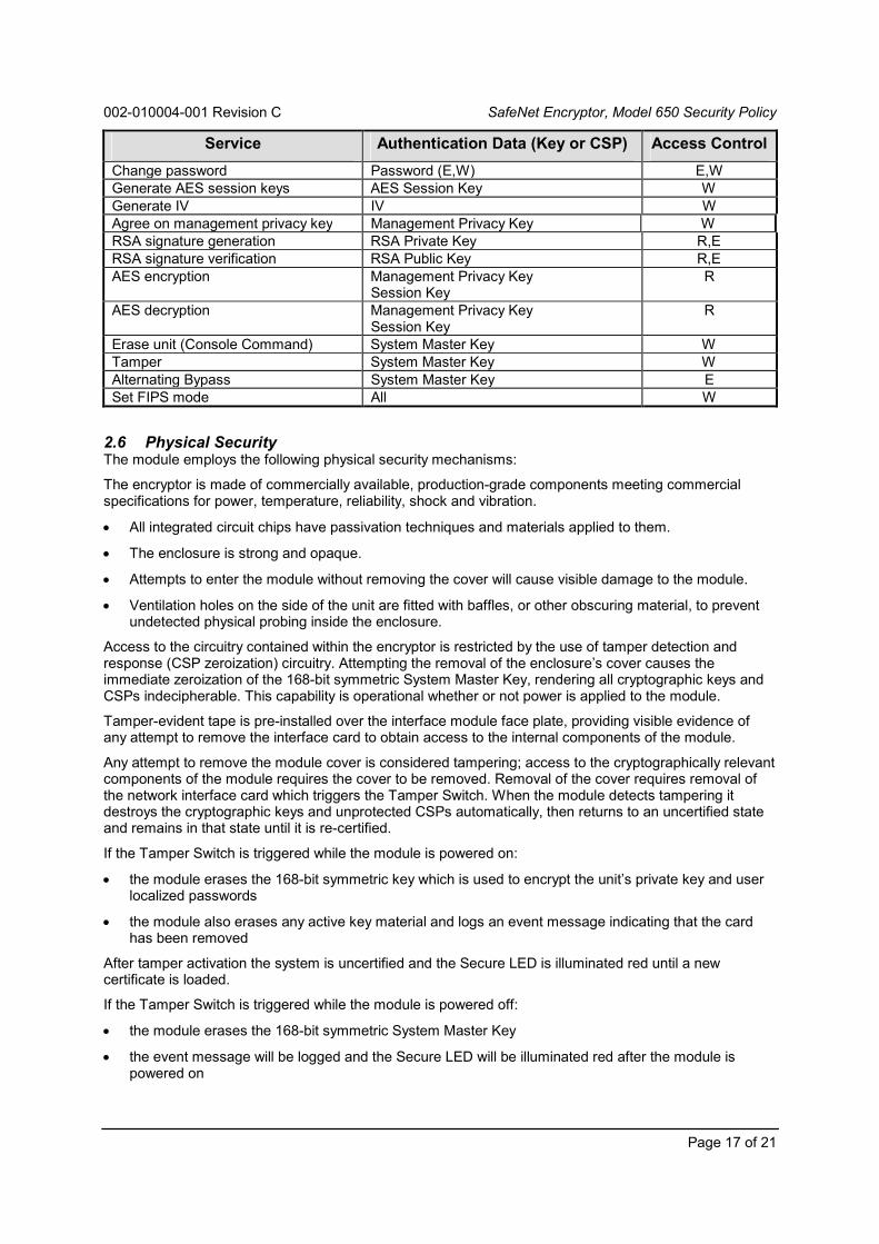
Page 17 of 21
Service Authentication Data (Key or CSP) Access Control
Change password Password (E,W) E,WGenerate AES session keys AES Session Key WGenerate IV IV WAgree on management privacy key Management Privacy Key WRSA signature generation RSA Private Key R,ERSA signature verification RSA Public Key R,EAES encryption Management Privacy Key
Session KeyR
AES decryption Management Privacy KeySession Key
R
Erase unit (Console Command) System Master Key WTamper System Master Key WAlternating Bypass System Master Key ESet FIPS mode All W
2.6 Physical SecurityThe module employs the following physical security mechanisms:
The encryptor is made of commercially available, production-grade components meeting commercialspecifications for power, temperature, reliability, shock and vibration.
All integrated circuit chips have passivation techniques and materials applied to them.
The enclosure is strong and opaque.
Attempts to enter the module without removing the cover will cause visible damage to the module.
Ventilation holes on the side of the unit are fitted with baffles, or other obscuring material, to preventundetected physical probing inside the enclosure.
Access to the circuitry contained within the encryptor is restricted by the use of tamper detection andresponse (CSP zeroization) circuitry. Attempting the removal of the enclosure’s cover causes theimmediate zeroization of the 168-bit symmetric System Master Key, rendering all cryptographic keys andCSPs indecipherable. This capability is operational whether or not power is applied to the module.
Tamper-evident tape is pre-installed over the interface module face plate, providing visible evidence ofany attempt to remove the interface card to obtain access to the internal components of the module.
Any attempt to remove the module cover is considered tampering; access to the cryptographically relevantcomponents of the module requires the cover to be removed. Removal of the cover requires removal ofthe network interface card which triggers the Tamper Switch. When the module detects tampering itdestroys the cryptographic keys and unprotected CSPs automatically, then returns to an uncertified stateand remains in that state until it is re-certified.
If the Tamper Switch is triggered while the module is powered on:
the module erases the 168-bit symmetric key which is used to encrypt the unit’s private key and userlocalized passwords
the module also erases any active key material and logs an event message indicating that the cardhas been removed
After tamper activation the system is uncertified and the Secure LED is illuminated red until a newcertificate is loaded.
If the Tamper Switch is triggered while the module is powered off:
the module erases the 168-bit symmetric System Master Key
the event message will be logged and the Secure LED will be illuminated red after the module ispowered on

002-010004-001 Revision C SafeNet Encryptor, Model 650 Security Policy
Page 18 of 21
While in the uncertified state, the CLI and SNMPv3 access are still active, but no user data is output fromthe module. The module indicates this state with the Secure LED illuminated red on the front panel.
In addition to the physical security mechanisms integrated with the module, the following recommendationshould be considered in the implementation of a Security Policy governing the installation and operation ofthe encryptors:
To ensure the security of the module during distribution and delivery, the User’s Guide containsprocedures in the Security Requirements section for inspection of the module by an authorizedoperator.
Secure access to the cryptographic module within a physically secure, limited access room orenvironment.
Table 2.6-1 outlines the recommended inspection and/or testing of the physical security mechanisms.
Table 2.6-1 Security Mechanism Inspection and Test
Physical SecurityMechanism
RecommendedFrequency of
Inspection/TestInspection/Test Guidance Details
Tamper Switch No direct inspection or test isrequired.
The module enters the tamper error statewhen the switch is tripped.
Once in this state, the module blocks all trafficuntil it is physically reset.
Tamper Evidence In accordance withorganization’s SecurityPolicy.
Inspect the enclosure and tamper evidenttape for physical signs of tampering orattempted access to the cryptographicmodule.
During normal operation, the Secure LED isilluminated green. If the unit is uncertified ortampered, the Secure LED is illuminated redand all traffic is blocked.
2.7 Self TestsIn addition to the physical security mechanisms noted in 2.6, the encryptor performs both power-up andconditional self tests to verify the integrity and correct operational functioning of the cryptographic module.If the system fails a self test, it transitions to an error state and blocks all traffic on the data ports. Table2.7-1 summarizes the system self tests.
Crypto Officers can run the power-up self-test on demand by issuing a reboot command. An operator withphysical access to the device can also run the power-up self-test on demand by cycling the power to themodule. Rebooting or power cycling the module causes the keys securing the connection to bereestablished after communications are restored.
The design of the cryptographic module ensures that all data output via the data output interface isinhibited whenever the module is in a self-test condition. Status information displaying the results of theself-tests is allowed from the status output interface, but no CSPs, plaintext data, or other information thatif misused could lead to a compromise is passed to the status output interface.
Table 2.7-1 Self Tests
Self Test Description

002-010004-001 Revision C SafeNet Encryptor, Model 650 Security Policy
Page 19 of 21
Self Test Description
Mandatory power-up tests performed at power-up and on demand:
Cryptographic AlgorithmKnown Answer Tests
Each cryptographic function, performed by the Encryptor, is tested using a“known answer” test to verify the operation of the function.
Algorithms tested: AES, HMAC, SHS (SHA-1, SHA-256, SHA-512),Triple-DES, RNG, RSA
Firmware The binary image(s) of the Encryptor’s firmware includes a 160-bit errordetection code (EDC) that allows the Encryptor to verify the integrity of thefirmware. The EDC is calculated for the image(s) and compared with theknown value(s), using a SHA hash, to confirm the integrity of the module.
Bypass The Connection Action Table (CAT) contains settings for bypass mode(configured administratively). Each time the CAT is changed, the systemgenerates a checksum and stores it as a parameter. On booting, thesystem calculates a fresh checksum and compares it to the stored valueto assure that the CAT rules have not changed or been corrupted. If thevalues do not match, the encryptor determines an error exists within theCAT. The encryptor sets an alarm and does not pass data (encrypted orunencrypted) to any connection.
To manually confirm the bypass configuration, review the settings in theCAT. This may be accomplished with the SMC application or via theconsole at the encryptor.
With SMC, log into the management application and select the targetencryptor from the Device table. Review device status on the Statustab or configure specific connection settings on the Security tab.Refer to the SMC documentation for details.
At the encryptor, log into the console and use the sessions command(SONET) or the tunnels command (Ethernet). Refer to the device fordetails.
Critical Functions tests performed at power-up:
Configuration Memory A test to verify the configuration memory integrity. An error detectionformula is calculated on all configuration memory and compared againstthe expected value (EDC), which is also stored in the configurationmemory. If failed, the unit attempts to correct the EDC and report thefailure.
Real Time Clock The real time clock is tested for valid time and date. If this test fails, thetime/date is set to 01-Jan-2000 at 00:00.
Battery The battery is tested to determine if it is critically low. This test isguaranteed to fail prior to the battery voltage falling below the minimumspecified data retention voltage for the associated battery-backedcomponents. If this test should fail, the battery low alarm condition will beon. The unit will continue to operate after taking whatever precautions arenecessary to guarantee correct operation.
General PurposeMemory
A destructive test verifies that the general purpose memory (RAM) isproperly operating, e.g., all legal addresses may be written to and readfrom, and that no address lines are open or shorted.
Tamper Memory Tamper memory is examined for evidence of Tamper.

002-010004-001 Revision C SafeNet Encryptor, Model 650 Security Policy
Page 20 of 21
Self Test Description
Conditional tests performed, as needed, during operation:
Pairwise consistency Public and private keys are used for the calculation and verification ofdigital signatures and also for key transport. Keys are tested forconsistency, according to their purpose, at the time they are generated.Encryption keys are tested by an encrypt/decrypt pairwise consistencytest while signature keys are tested by a sign/verify pairwise consistencytest.
Algorithms tested: RSA
Firmware load Test to verify the authenticity of any software/firmware load that is appliedto the Encryptor in the field. The software/firmware RSA signature isverified.
Continuous RNG This test is a “stuck at” test to check the RNG output data for failure to aconstant value. All internal RNGs are subject to this test.

002-010004-001 Revision C SafeNet Encryptor, Model 650 Security Policy
Page 21 of 21
3 Glossary of Acronyms, Terms and Abbreviations
Term Definition
AES Advanced Encryption Standard
ATM Asynchronous Transfer Mode
CBC Cipher Block Chaining
CFB Cipher Feedback
CLI Command Line Interface
CMVP Cryptographic Module Validation Program
CSE Communications Security Establishment
CSP Critical Security Parameter
DES, Triple-DES Data Encryption Standard
EDC Error Detection Code
EMC Electromagnetic Compatibility
EMI Electromagnetic Interference
FCC Federal Communication Commission
FIPS Federal Information Processing Standard
HMAC (Keyed) Hash Message Authentication Code
IP Internet Protocol
KAT Known Answer Test
LAN Local Area Network
LED Light Emitting Diode
MIB Management Information Block
MPK Management Privacy Key
MSK Master Session Key
NC Network Certificate
NIST National Institute of Standards and Technology
NVLAP National Voluntary Laboratory Accreditation Program
PRNG Pseudo Random Number Generator
PUB Publication
RAM Random Access Memory
RFC Request for Comment
ROM Read Only Memory
RNG Random Number Generator
RSA Rivest Shamir and Adleman (public key algorithm)
SDH Synchronous Digital Hierarchy
SHA Secure Hash Algorithm
SK Session Key
SMC Security Management Center
SMK System Master Key
SNMPv3 Simple Network Management Protocol version 3
SONET Synchronous Optical Network
SSE SafeNet SONET Encryptor
SEE SafeNet Ethernet Encryptor
VCAT Virtual Channel Action Table
X.509 Digital Certificate Standard RFC 2459