SAFE LOADING PASS SCHEME Inspection Manual · INSPECTION MANUAL 2 Acknowledgement ... offside of...
40
Inspection Manual SAFE LOADING PASS SCHEME
Transcript of SAFE LOADING PASS SCHEME Inspection Manual · INSPECTION MANUAL 2 Acknowledgement ... offside of...
Inspection Manual
SAFE LOADING
PASS SCHEME

Contents
The principle for the standard method of inspection 3
1 Tank certificates (not applicable to tractors) 4
1.1 Tank certificate – initial/intermediate/periodic 41.2 Tank certificate – vapour tightness 4
2 Cab interior 4
2.1 Roof hatch 42.2 Fire extinguisher 42.3 Tachograph 52.4 Additional in-cab electrical equipment 52.5 Battery master switch control 62.6 Daytime running lights (DRLs) and automatically
powered headlights 62.7 Night heater (If fitted) 72.8 Cigarette lighter socket 72.9 Electrically operated/heated mirrors 7
3 Cab exterior 7
3.1 Wiring in door apertures 73.2 Electrically heated/operated mirrors 73.3 Cab front top outline marker lamps (or other light(s)
used to indicate battery master switch is switched ‘on’) 83.4 Cab front lights 83.5 Male C type air coupling 83.6 Rear engine cover and exhaust system 83.7 Rear window (if fitted) 9
4 Batteries, battery master switch and associated equipment 9
4.1 Battery box cover 94.2 Batteries 104.3 Cables to the battery master switch 104.4 Battery master switch negative relay 104.5 Tachograph power cable 114.6 Battery boost socket (if fitted) 114.7 Battery master switch external controls 114.8 Battery main earth point 12
5 Electrical system (external to the cab) 12
5.1 Conductors (wiring) 125.2 Light units and other electrical components 135.3 Additional operation/work lamps 135.4 Permanently powered equipment (if fitted) 13
6 General equipment external to the cab 13
6.1 Tyres 136.2 Mudwings 146.3 Fire extinguisher(s) 156.4 Electrical continuity to fifth wheel coupling and
drive axle (tractors) 15
7 Inspection of the tank plates, tank status, the tank, footvalves and pipework (ground level) 16
7.1 Tank plates 167.2 Tank status 167.3 The complete tank shell including its (integral) supports 177.4 The (vehicle mounted) mountings for the tank
(if applicable) 177.5 Tank mounting fasteners (including trailer upper coupler
for the 5th wheel and rear subframe (if fitted)) 177.6 Footvalves 187.7 External product pipework, flanges and gaskets 18
8 Inspection of the control system, interlocks and guard bar 18
8.1 Control cabinet 188.2 Anti-drive away function 198.3 Guard bar (or cabinet door) covering the loading
adaptors 208.4 Control system – vapour transfer valves and
emergency shut down operators 208.5 Control system – footvalve operation 21
9 Inspection of labels and hazard panels 21
9.1 Notices and labels 219.2 Compartment capacity and number for each
compartment 219.3 Non pressure balanced footvalves fitted 219.4 Overfill prevention system type (number of wires) 219.5 Maximum number of compartments that may be
loaded simultaneously (for a tanker which carries petrol) 22
9.6 Grade/product indicators (if fitted) 229.7 Hazard warning panels 22
10 Inspection of loading connections 22
10.1 Loading adaptor caps 2210.2 Loading adaptors 2310.3 Vapour adaptor 2410.4 Overfill prevention socket 2410.5 Pressure switch 25
11 Inspection of the tank top (including service equipment) 25
11.1 Tank top condition 2511.2 Tank top drainage 2511.3 Pneumatic system on tank top 2511.4 Manhole covers and neckrings (approx 500mm
diameter) 2611.5 Dip caps and mandrels (where fitted) 2611.6 Vapour transfer valve (VTV) and hose connection to
manifold 2611.7 Emergency pressure relief valve (EPRV) 27
12 Tank/compartment internal inspection 28
12.1 Breather valve (Pressure – vacuum valve) 2812.2 Compartment internal inspection (freedom from
debris and integrity) 2812.3 Central conductor (where required) 2812.4 Footvalve installation/deflector plate 2912.5 Overfill prevention system sensors 29
13 Electrical continuity checks – ground level 30
13.1 Earth pin to tank and service equipment 3013.2 Earth pin to axles and wheels 30
Annex A: Roof hatch 31
Annex B: Additional in-cab electrical equipment 32
Annex C: Battery main earth point 33
Annex D: Electrical system external to the cab 34
Annex E: Repairs to mudwings of non-metallic material 35
Annex F: Anti-drive away function test 36
Annex G: Overfill prevention system sensors 37
Annex H: Inpsection forms 38
INSPECTION MANUAL
2
Acknowledgement
The following text is reproduced with permission from the Energy Institute’s publication: Petroleum road tankers: Recommendations for a standard method of inspection for a safe loading pass (first edition).
INSPECTION MANUAL
3
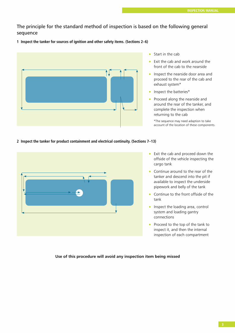
The principle for the standard method of inspection is based on the following general sequence
1 Inspect the tanker for sources of ignition and other safety items. (Sections 2–6)
• Start in the cab
• Exit the cab and work around the front of the cab to the nearside
• Inspect the nearside door area and proceed to the rear of the cab and exhaust system*
• Inspect the batteries*
• Proceed along the nearside and around the rear of the tanker, and complete the inspection when returning to the cab
*The sequence may need adaption to take account of the location of these components.
2 Inspect the tanker for product containment and electrical continuity. (Sections 7–13)
• Exit the cab and proceed down the offside of the vehicle inspecting the cargo tank
• Continue around to the rear of the tanker and descend into the pit if available to inspect the underside pipework and belly of the tank
• Continue to the front offside of the tank
• Inspect the loading area, control system and loading gantry connections
• Proceed to the top of the tank to inspect it, and then the internal inspection of each compartment
Use of this procedure will avoid any inspection item being missed
INSPECTION MANUAL
4
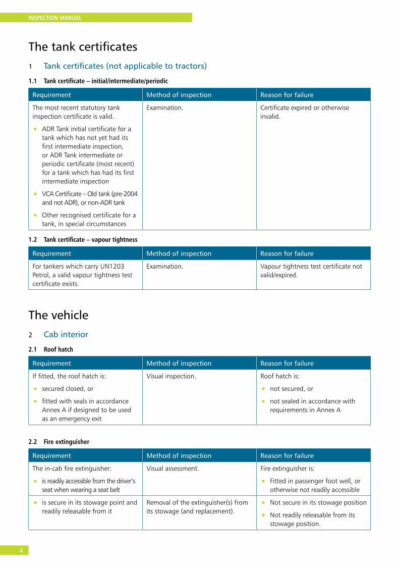
The tank certificates1 Tank certificates (not applicable to tractors)
1.1 Tank certificate – initial/intermediate/periodic
Requirement Method of inspection Reason for failure
The most recent statutory tank inspection certificate is valid.
• ADR Tank initial certificate for a tank which has not yet had its first intermediate inspection, or ADR Tank intermediate or periodic certificate (most recent) for a tank which has had its first intermediate inspection
• VCA Certificate – Old tank (pre-2004 and not ADR), or non-ADR tank
• Other recognised certificate for a tank, in special circumstances
Examination. Certificate expired or otherwise invalid.
1.2 Tank certificate – vapour tightness
Requirement Method of inspection Reason for failure
For tankers which carry UN1203 Petrol, a valid vapour tightness test certificate exists.
Examination. Vapour tightness test certificate not valid/expired.
The vehicle2 Cab interior
2.1 Roof hatch
Requirement Method of inspection Reason for failure
If fitted, the roof hatch is:
• secured closed, or
• fitted with seals in accordance Annex A if designed to be used as an emergency exit
Visual inspection. Roof hatch is:
• not secured, or
• not sealed in accordance with requirements in Annex A
2.2 Fire extinguisher
Requirement Method of inspection Reason for failure
The in-cab fire extinguisher:
• is readily accessible from the driver’s seat when wearing a seat belt
Visual assessment. Fire extinguisher is:
• Fitted in passenger foot well, or otherwise not readily accessible
• is secure in its stowage point and readily releasable from it
Removal of the extinguisher(s) from its stowage (and replacement).
• Not secure in its stowage position
• Not readily releasable from its stowage position.
INSPECTION MANUAL
5
Requirement Method of inspection Reason for failure
• has a holder/stowage which is itself secure
Manipulation. • Stowage insecure
• is serviceable Visual inspection. • Container or mechanism damaged
• Next inspection date passed
• Security seal damaged or broken
• Pressure gauge needle not showing in the green section
2.3 Tachograph
Requirement Method of inspection Reason for failure
The tachograph is Ex marked. Visual inspection. Tachograph not clearly Ex marked.
2.4 Additional in-cab electrical equipment
Requirement Method of inspection Reason for failure
Any added in-cab electrical equipment, including any cab phone/communication system, is secure.
Any exposed wiring is secure, with grommets and glands in place as appropriate.
Visual inspection. Insecurity of any added electrical equipment.
Wiring insecure.
Grommets and glands not fitted to components or missing.
Where equipment is permanently powered from the vehicle battery, it is:
• Ex certified
• fed via an Ex fuse
• fed by a cable which complies with section 4.5
• provided with a certificate in accordance Annex B
Visual inspection. Equipment permanently powered and is:
• not Ex certified
• not fed via an Ex fuse
• fed by a cable which does not comply with 4.5
• not provided with a certificate in accordance with Annex B
Where equipment is powered from its own button cell battery and has no electrical socket, no additional requirements apply.
Visual inspection. –
Where equipment is powered from its own battery:
• which is not a button cell
• and/or has an electrical socket (indicating a lithium ion cell is used)
The equipment is fitted with an ‘on-off’ switch.
Visual inspection. Equipment powered with its own battery other than a button cell:
• and/or having an electrical socket
• having no ‘on-off’ switch
INSPECTION MANUAL
6
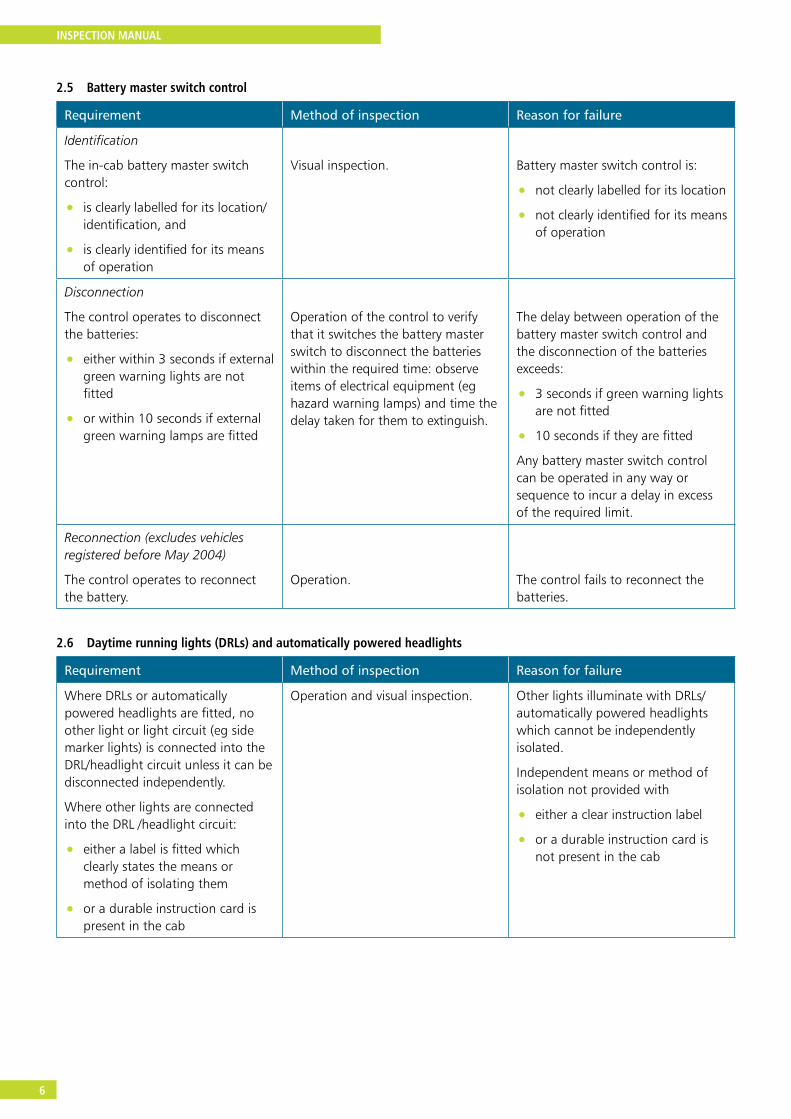
2.5 Battery master switch control
Requirement Method of inspection Reason for failure
Identification
The in-cab battery master switch control:
• is clearly labelled for its location/identification, and
• is clearly identified for its means of operation
Visual inspection. Battery master switch control is:
• not clearly labelled for its location
• not clearly identified for its means of operation
Disconnection
The control operates to disconnect the batteries:
• either within 3 seconds if external green warning lights are not fitted
• or within 10 seconds if external green warning lamps are fitted
Operation of the control to verify that it switches the battery master switch to disconnect the batteries within the required time: observe items of electrical equipment (eg hazard warning lamps) and time the delay taken for them to extinguish.
The delay between operation of the battery master switch control and the disconnection of the batteries exceeds:
• 3 seconds if green warning lights are not fitted
• 10 seconds if they are fitted
Any battery master switch control can be operated in any way or sequence to incur a delay in excess of the required limit.
Reconnection (excludes vehicles registered before May 2004)
The control operates to reconnect the battery.
Operation.
The control fails to reconnect the batteries.
2.6 Daytime running lights (DRLs) and automatically powered headlights
Requirement Method of inspection Reason for failure
Where DRLs or automatically powered headlights are fitted, no other light or light circuit (eg side marker lights) is connected into the DRL/headlight circuit unless it can be disconnected independently.
Where other lights are connected into the DRL /headlight circuit:
• either a label is fitted which clearly states the means or method of isolating them
• or a durable instruction card is present in the cab
Operation and visual inspection. Other lights illuminate with DRLs/automatically powered headlights which cannot be independently isolated.
Independent means or method of isolation not provided with
• either a clear instruction label
• or a durable instruction card is not present in the cab

INSPECTION MANUAL
7
2.7 Night heater (If fitted)
Requirement Method of inspection Reason for failure
Any night heater is fitted with an isolation switch.
The switch is clearly labelled.
Visual inspection and operation.
Visual inspection.
Night heater not fitted with an isolation switch.
Switch not clearly labelled.
2.8 Cigarette lighter socket
Requirement Method of inspection Reason for failure
No socket is fitted. Visual inspection. A socket is fitted (whether or not disconnected).
2.9 Electrically operated/heated mirrors
Requirement Method of inspection Reason for failure
If electrically adjustable, mirrors adjust correctly.
Note: to check the heating function (if fitted), switch on heaters and check glass(es) for temperature when inspecting the doors.
Operation and visual inspection.
(The heating function is checked at 3.2).
If fitted, remote adjustment of either mirror does not function.
Switch on all lights and heated mirror elements before leaving the cab. Commence to exit the cab in order to inspect the chassis equipment of the tanker including its electrical system.
Note: entry to the cab will be required again to test the anti-drive away interlock (see section 7.2).
3 Cab exterior
3.1 Wiring in door apertures
Note: wiring in the driver’s door aperture is checked at this point when exiting the cab, and that of the passenger’s door aperture is checked in sequence between 3.5 and 3.6.
Requirement Method of inspection Reason for failure
Wiring to the door and mirror is secure and free from damage.
Visual inspection. Evidence of chafing, pinching or other damage to cables.
Inadequately secured, protected or routed cables.
3.2 Electrically heated/operated mirrors
Requirement Method of inspection Reason for failure
If electrically heated, the offside mirror heats, is secure and free from damage.
Tactile inspection.
Visual inspection and operation.
Mirror glass fails to heat.
Mirror assembly/glass/heating element insecure.

INSPECTION MANUAL
8
Inspection of the cab front
3.3 Cab front top outline marker lamps (or other light(s) used to indicate battery master switch is switched ‘on’)
Requirement Method of inspection Reason for failure
Each cab front top outline marker light (or other light) is illuminated when the battery master switch is switched ‘on’.
Operation and visual inspection. Light(s) fail to illuminate/extinguish as intended.
3.4 Cab front lights
Requirement Method of inspection Reason for failure
Each front showing light unit:
• is operational
• is free from damage and in good condition
Visual inspection.
Light not working.
• Cracked, broken or insecure lens
• If multi-LED light unit, more than 1 in 4 LEDs are not illuminated
3.5 Male C type air coupling
Requirement Method of inspection Reason for failure
A male ‘C’ type air coupling for charging the air system in an emergency is fitted (with a separate non-return valve), accessible from the front of the vehicle.
Visual inspection. Valve not a male ‘C’ type.
• Coupling missing, damaged or unprotected
• Coupling not accessible from the front of the vehicle
The valve is operational. Use of compressed air line fitted female ‘C’ type coupling with non-return valve.
Valve seized or fails to return closed.
Inspection of the passenger side of the cab, and the rear
Note: wiring in the passenger’s door aperture is checked at this stage in the sequence: see 3.1
3.6 Rear engine cover and exhaust system
Requirement Method of inspection Reason for failure
The rear engine cover is secure and has a minimum number of apertures.
It effectively covers all parts of the engine and exhaust system except where the silencer has a surface temperature less than 200°C and carries a manufacturer’s label accordingly.
Visual inspection and manipulation. Rear engine cover insecure/incomplete/damaged – cracked or broken.
Rear engine cover fails to cover rear of engine and exhaust system (except silencer declared to have a maximum surface temperature less than 200°C as attested by a label fitted by its manufacturer).
INSPECTION MANUAL
9
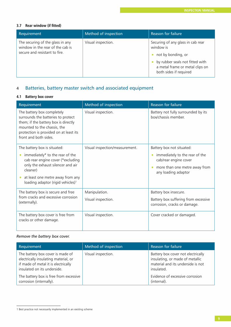
3.7 Rear window (if fitted)
Requirement Method of inspection Reason for failure
The securing of the glass in any window in the rear of the cab is secure and resistant to fire.
Visual inspection. Securing of any glass in cab rear window is
• not by bonding, or
• by rubber seals not fitted with a metal frame or metal clips on both sides if required
4 Batteries, battery master switch and associated equipment
4.1 Battery box cover
Requirement Method of inspection Reason for failure
The battery box completely surrounds the batteries to protect them; if the battery box is directly mounted to the chassis, the protection is provided on at least its front and both sides.
Visual inspection. Battery not fully surrounded by its box/chassis member.
The battery box is situated:
• immediately* to the rear of the cab rear engine cover (*excluding only the exhaust silencer and air cleaner)
• at least one metre away from any loading adaptor (rigid vehicles)1
Visual inspection/measurement. Battery box not situated:
• immediately to the rear of the cab/rear engine cover
• more than one metre away from any loading adaptor
The battery box is secure and free from cracks and excessive corrosion (externally).
Manipulation.
Visual inspection.
Battery box insecure.
Battery box suffering from excessive corrosion, cracks or damage.
The battery box cover is free from cracks or other damage.
Visual inspection. Cover cracked or damaged.
Remove the battery box cover.
Requirement Method of inspection Reason for failure
The battery box cover is made of electrically insulating material, or if made of metal it is electrically insulated on its underside.
The battery box is free from excessive corrosion (internally).
Visual inspection. Battery box cover not electrically insulating, or made of metallic material and its underside is not insulated.
Evidence of excessive corrosion (internal).
1 Best practice not necessarily implemented in an existing scheme
INSPECTION MANUAL
10
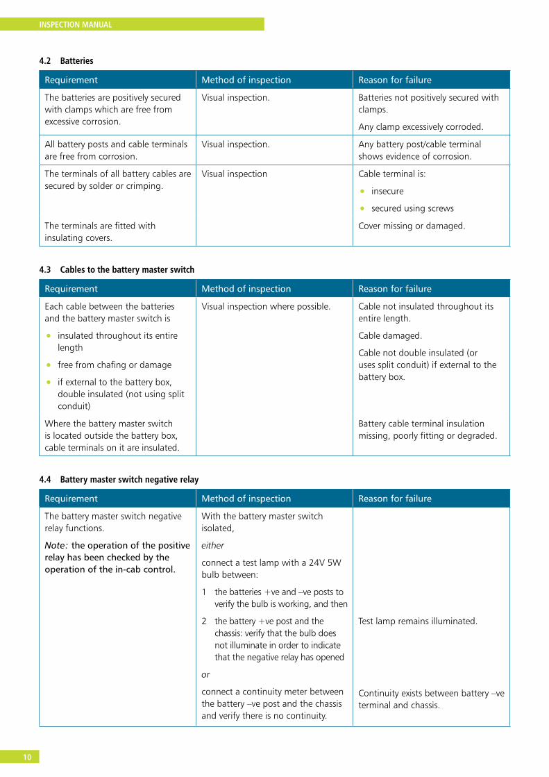
4.2 Batteries
Requirement Method of inspection Reason for failure
The batteries are positively secured with clamps which are free from excessive corrosion.
Visual inspection. Batteries not positively secured with clamps.
Any clamp excessively corroded.
All battery posts and cable terminals are free from corrosion.
Visual inspection. Any battery post/cable terminal shows evidence of corrosion.
The terminals of all battery cables are secured by solder or crimping.
Visual inspection Cable terminal is:
• insecure
• secured using screws
The terminals are fitted with insulating covers.
Cover missing or damaged.
4.3 Cables to the battery master switch
Requirement Method of inspection Reason for failure
Each cable between the batteries and the battery master switch is
• insulated throughout its entire length
• free from chafing or damage
• if external to the battery box, double insulated (not using split conduit)
Visual inspection where possible. Cable not insulated throughout its entire length.
Cable damaged.
Cable not double insulated (or uses split conduit) if external to the battery box.
Where the battery master switch is located outside the battery box, cable terminals on it are insulated.
Battery cable terminal insulation missing, poorly fitting or degraded.
4.4 Battery master switch negative relay
Requirement Method of inspection Reason for failure
The battery master switch negative relay functions.
Note: the operation of the positive relay has been checked by the operation of the in-cab control.
With the battery master switch isolated,
either
connect a test lamp with a 24V 5W bulb between:
1 the batteries +ve and –ve posts to verify the bulb is working, and then
2 the battery +ve post and the chassis: verify that the bulb does not illuminate in order to indicate that the negative relay has opened
or
connect a continuity meter between the battery –ve post and the chassis and verify there is no continuity.
Test lamp remains illuminated.
Continuity exists between battery –ve terminal and chassis.

INSPECTION MANUAL
11
4.5 Tachograph power cable
Requirement Method of inspection Reason for failure
The power supply cable to the tachograph from its Ex – certified fuse is dedicated and distinguishable throughout its length from other cables by its construction or marking.
Visual inspection. Cable not dedicated.
Cable indistinguishable from other cables.
4.6 Battery boost socket (if fitted)
Requirement Method of inspection Reason for failure
The boost socket is connected to the switched side of the battery master switch.
Its contacts are fitted with an insulating cover or covers.
Visual inspection. Socket connected to the live side of the battery master switch.
Insulating cover(s) cracked, broken or not fitted.
Replace the battery box cover.
4.7 Battery master switch external controls
Requirement Method of inspection Reason for failure
The location and means of operation of each battery master switch control as fitted are clearly identified by a label or labels.
Visual inspection. Battery master switch control not clearly labelled to show its:
• location
• means of operation
Each control operates to isolate the batteries:
• within 3 seconds if external green warning lights are not fitted, or
• within 10 seconds if external green warning lamps are fitted
Operation of each control individually to ensure that it switches the battery master switch to isolate the batteries within the required time.
(Observe items of electrical equipment (eg headlamps) and time the delay to extinguish.)
Battery master switch fails to respond to each control.
The delay between the operation of a battery master switch control and the isolation of the batteries exceeds:
• 3 seconds if green warning lights are not fitted
• 10 seconds if green warning lights are fitted
The battery master switch control can be operated in any way or sequence to incur a delay in excess of the required limit.
Where a delay of more than three seconds occurs between operating any battery master switch control and the battery master switch relays operating, and where any external control is fitted:
• a green warning light is fitted adjacent to it and
• it is/they are operational
Visual inspection. Light not fitted.
Light not working. (If multi-LED light unit, more than one in four LEDs are not illuminated.)
INSPECTION MANUAL
12
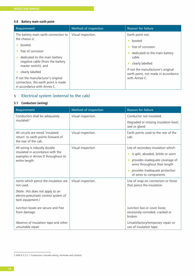
4.8 Battery main earth point
Requirement Method of inspection Reason for failure
The battery main earth connection to the chassis is:
• booted
• free of corrosion
• dedicated to the main battery negative cable (from the battery master switch), and
• clearly labelled
If not the manufacturer’s original connection, the earth point is made in accordance with Annex C.
Visual inspection. Earth point not:
• booted
• free of corrosion
• dedicated to the main battery cable
• clearly labelled
If not the manufacturer’s original earth point, not made in accordance with Annex C.
5 Electrical system (external to the cab)
5.1 Conductors (wiring)
Requirement Method of inspection Reason for failure
Conductors shall be adequately insulated.2
Visual inspection. Conductor not insulated.
Degraded or missing insulation boot, seal or gland.
All circuits are wired ‘insulated return’ to earth points forward of the rear of the cab.
Visual inspection. Earth points used to the rear of the cab.
All wiring is robustly double insulated in accordance with the examples in Annex D throughout its entire length.
Visual inspection. Use of secondary insulation which:
• is split, abraded, brittle or worn
• provides inadequate coverage of wires throughout their length
• provides inadequate protection of wires to components
Joints which pierce the insulation are not used.
(Note: this does not apply to an electro-pneumatic control system of tank equipment.)
Visual inspection. Use of snap-on connectors or those that pierce the insulation.
Junction boxes are secure and free from damage.
Junction box or cover loose, excessively corroded, cracked or broken.
Absence of insulation tape and other unsuitable repair.
Unsatisfactory/temporary repair or use of insulation tape.
2 ADR 9.2.2.2.1 ‘Conductors’ includes wiring, terminals and contacts
INSPECTION MANUAL
13
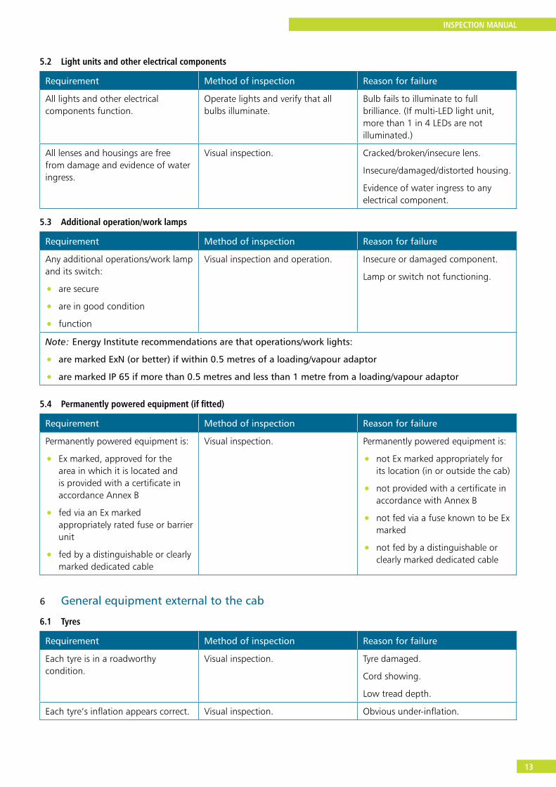
5.2 Light units and other electrical components
Requirement Method of inspection Reason for failure
All lights and other electrical components function.
Operate lights and verify that all bulbs illuminate.
Bulb fails to illuminate to full brilliance. (If multi-LED light unit, more than 1 in 4 LEDs are not illuminated.)
All lenses and housings are free from damage and evidence of water ingress.
Visual inspection. Cracked/broken/insecure lens.
Insecure/damaged/distorted housing.
Evidence of water ingress to any electrical component.
5.3 Additional operation/work lamps
Requirement Method of inspection Reason for failure
Any additional operations/work lamp and its switch:
• are secure
• are in good condition
• function
Visual inspection and operation. Insecure or damaged component.
Lamp or switch not functioning.
Note: Energy Institute recommendations are that operations/work lights:
• are marked ExN (or better) if within 0.5 metres of a loading/vapour adaptor
• are marked IP 65 if more than 0.5 metres and less than 1 metre from a loading/vapour adaptor
5.4 Permanently powered equipment (if fitted)
Requirement Method of inspection Reason for failure
Permanently powered equipment is:
• Ex marked, approved for the area in which it is located and is provided with a certificate in accordance Annex B
• fed via an Ex marked appropriately rated fuse or barrier unit
• fed by a distinguishable or clearly marked dedicated cable
Visual inspection. Permanently powered equipment is:
• not Ex marked appropriately for its location (in or outside the cab)
• not provided with a certificate in accordance with Annex B
• not fed via a fuse known to be Ex marked
• not fed by a distinguishable or clearly marked dedicated cable
6 General equipment external to the cab
6.1 Tyres
Requirement Method of inspection Reason for failure
Each tyre is in a roadworthy condition.
Visual inspection. Tyre damaged.
Cord showing.
Low tread depth.
Each tyre’s inflation appears correct. Visual inspection. Obvious under-inflation.
INSPECTION MANUAL
14
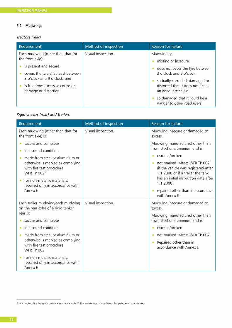
6.2 Mudwings
Tractors (rear)
Requirement Method of inspection Reason for failure
Each mudwing (other than that for the front axle):
• is present and secure
• covers the tyre(s) at least between 3 o’clock and 9 o’clock; and
• is free from excessive corrosion, damage or distortion
Visual inspection. Mudwing is:
• missing or insecure
• does not cover the tyre between 3 o’clock and 9 o’clock
• so badly corroded, damaged or distorted that it does not act as an adequate shield
• so damaged that it could be a danger to other road users
Rigid chassis (rear) and trailers
Requirement Method of inspection Reason for failure
Each mudwing (other than that for the front axle) is:
• secure and complete
• in a sound condition
• made from steel or aluminium or otherwise is marked as complying with fire test procedure WFR TP 0023
• for non-metallic materials, repaired only in accordance with Annex E
Visual inspection. Mudwing insecure or damaged to excess.
Mudwing manufactured other than from steel or aluminium and is:
• cracked/broken
• not marked ‘Meets WFR TP 002’ (if the vehicle was registered after 1.1 2000 or if a trailer the tank has an initial inspection date after 1.1.2000)
• repaired other than in accordance with Annex E
Each trailer mudwing/each mudwing on the rear axles of a rigid tanker rear is:
• secure and complete
• in a sound condition
• made from steel or aluminium or otherwise is marked as complying with fire test procedure WFR TP 002
• for non-metallic materials, repaired only in accordance with Annex E
Visual inspection. Mudwing insecure or damaged to excess.
Mudwing manufactured other than from steel or aluminium and is:
• cracked/broken
• not marked ‘Meets WFR TP 002’
• Repaired other than in accordance with Annex E
3 Warrington Fire Research test in accordance with E1 Fire resistatnce of mudwings for petroleum road tankers
INSPECTION MANUAL
15
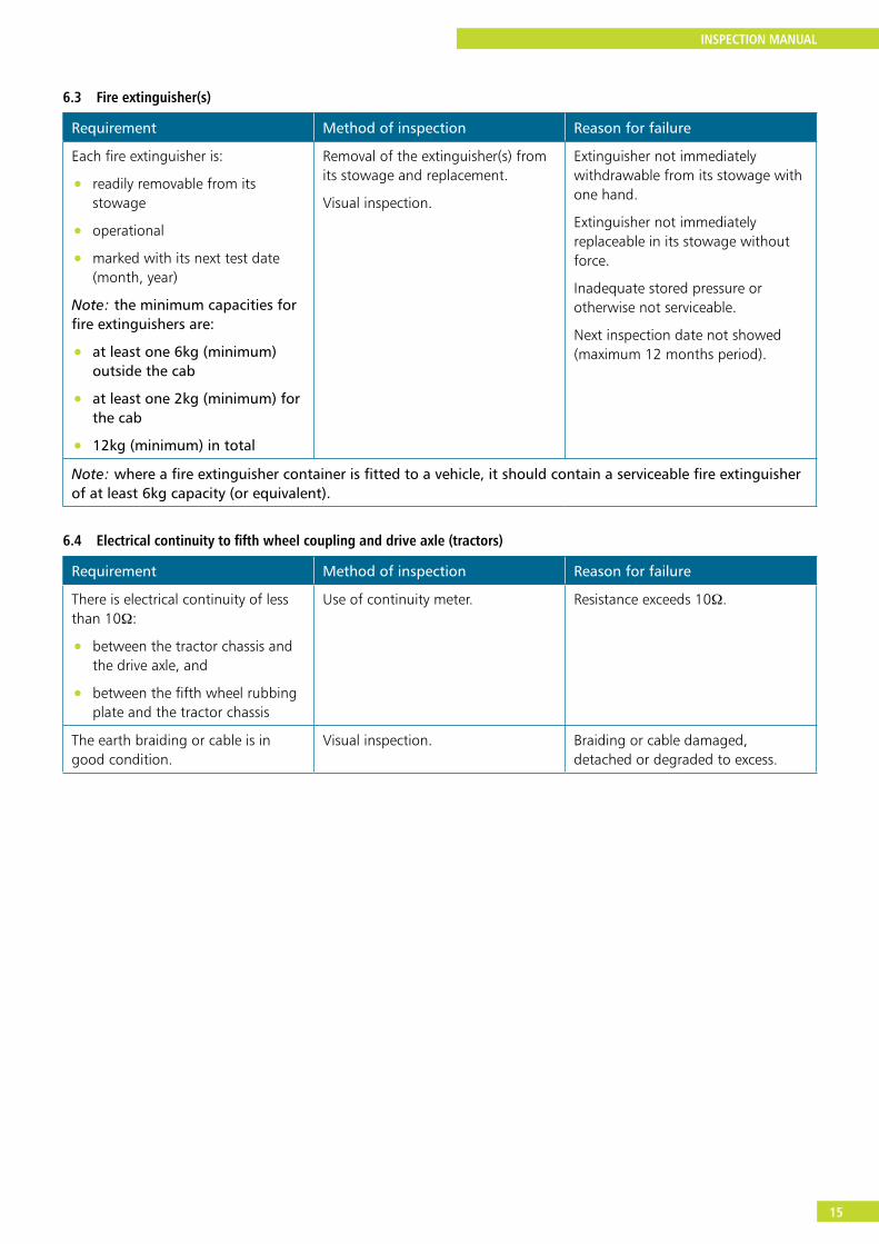
6.3 Fire extinguisher(s)
Requirement Method of inspection Reason for failure
Each fire extinguisher is:
• readily removable from its stowage
• operational
• marked with its next test date (month, year)
Note: the minimum capacities for fire extinguishers are:
• at least one 6kg (minimum) outside the cab
• at least one 2kg (minimum) for the cab
• 12kg (minimum) in total
Removal of the extinguisher(s) from its stowage and replacement.
Visual inspection.
Extinguisher not immediately withdrawable from its stowage with one hand.
Extinguisher not immediately replaceable in its stowage without force.
Inadequate stored pressure or otherwise not serviceable.
Next inspection date not showed (maximum 12 months period).
Note: where a fire extinguisher container is fitted to a vehicle, it should contain a serviceable fire extinguisher of at least 6kg capacity (or equivalent).
6.4 Electrical continuity to fifth wheel coupling and drive axle (tractors)
Requirement Method of inspection Reason for failure
There is electrical continuity of less than 10Ω:
• between the tractor chassis and the drive axle, and
• between the fifth wheel rubbing plate and the tractor chassis
Use of continuity meter. Resistance exceeds 10Ω.
The earth braiding or cable is in good condition.
Visual inspection. Braiding or cable damaged, detached or degraded to excess.
INSPECTION MANUAL
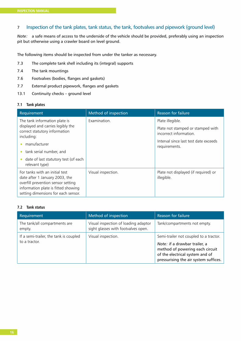
16
7 Inspection of the tank plates, tank status, the tank, footvalves and pipework (ground level)
Note: a safe means of access to the underside of the vehicle should be provided, preferably using an inspection pit but otherwise using a crawler board on level ground.
The following items should be inspected from under the tanker as necessary.
7.3 The complete tank shell including its (integral) supports
7.4 The tank mountings
7.6 Footvalves (bodies, flanges and gaskets)
7.7 External product pipework, flanges and gaskets
13.1 Continuity checks – ground level
7.1 Tank plates
Requirement Method of inspection Reason for failure
The tank information plate is displayed and carries legibly the correct statutory information including:
• manufacturer
• tank serial number, and
• date of last statutory test (of each relevant type)
Examination. Plate illegible.
Plate not stamped or stamped with incorrect information.
Interval since last test date exceeds requirements.
For tanks with an initial test date after 1 January 2003, the overfill prevention sensor setting information plate is fitted showing setting dimensions for each sensor.
Visual inspection. Plate not displayed (if required) or illegible.
7.2 Tank status
Requirement Method of inspection Reason for failure
The tank/all compartments are empty.
Visual inspection of loading adaptor sight glasses with footvalves open.
Tank/compartments not empty.
If a semi-trailer, the tank is coupled to a tractor.
Visual inspection. Semi-trailer not coupled to a tractor.
Note: if a drawbar trailer, a method of powering each circuit of the electrical system and of pressurising the air system suffices.
INSPECTION MANUAL
17
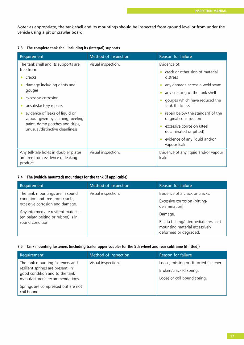
Note: as appropriate, the tank shell and its mountings should be inspected from ground level or from under the vehicle using a pit or crawler board.
7.3 The complete tank shell including its (integral) supports
Requirement Method of inspection Reason for failure
The tank shell and its supports are free from:
• cracks
• damage including dents and gouges
• excessive corrosion
• unsatisfactory repairs
• evidence of leaks of liquid or vapour given by staining, peeling paint, damp patches and drips, unusual/distinctive cleanliness
Visual inspection. Evidence of:
• crack or other sign of material distress
• any damage across a weld seam
• any creasing of the tank shell
• gouges which have reduced the tank thickness
• repair below the standard of the original construction
• excessive corrosion (steel delaminated or pitted)
• evidence of any liquid and/or vapour leak
Any tell-tale holes in doubler plates are free from evidence of leaking product.
Visual inspection. Evidence of any liquid and/or vapour leak.
7.4 The (vehicle mounted) mountings for the tank (if applicable)
Requirement Method of inspection Reason for failure
The tank mountings are in sound condition and free from cracks, excessive corrosion and damage.
Any intermediate resilient material (eg balata belting or rubber) is in sound condition.
Visual inspection. Evidence of a crack or cracks.
Excessive corrosion (pitting/delamination).
Damage.
Balata belting/intermediate resilient mounting material excessively deformed or degraded.
7.5 Tank mounting fasteners (including trailer upper coupler for the 5th wheel and rear subframe (if fitted))
Requirement Method of inspection Reason for failure
The tank mounting fasteners and resilient springs are present, in good condition and to the tank manufacturer’s recommendations.
Springs are compressed but are not coil bound.
Visual inspection. Loose, missing or distorted fastener.
Broken/cracked spring.
Loose or coil bound spring.
INSPECTION MANUAL
18
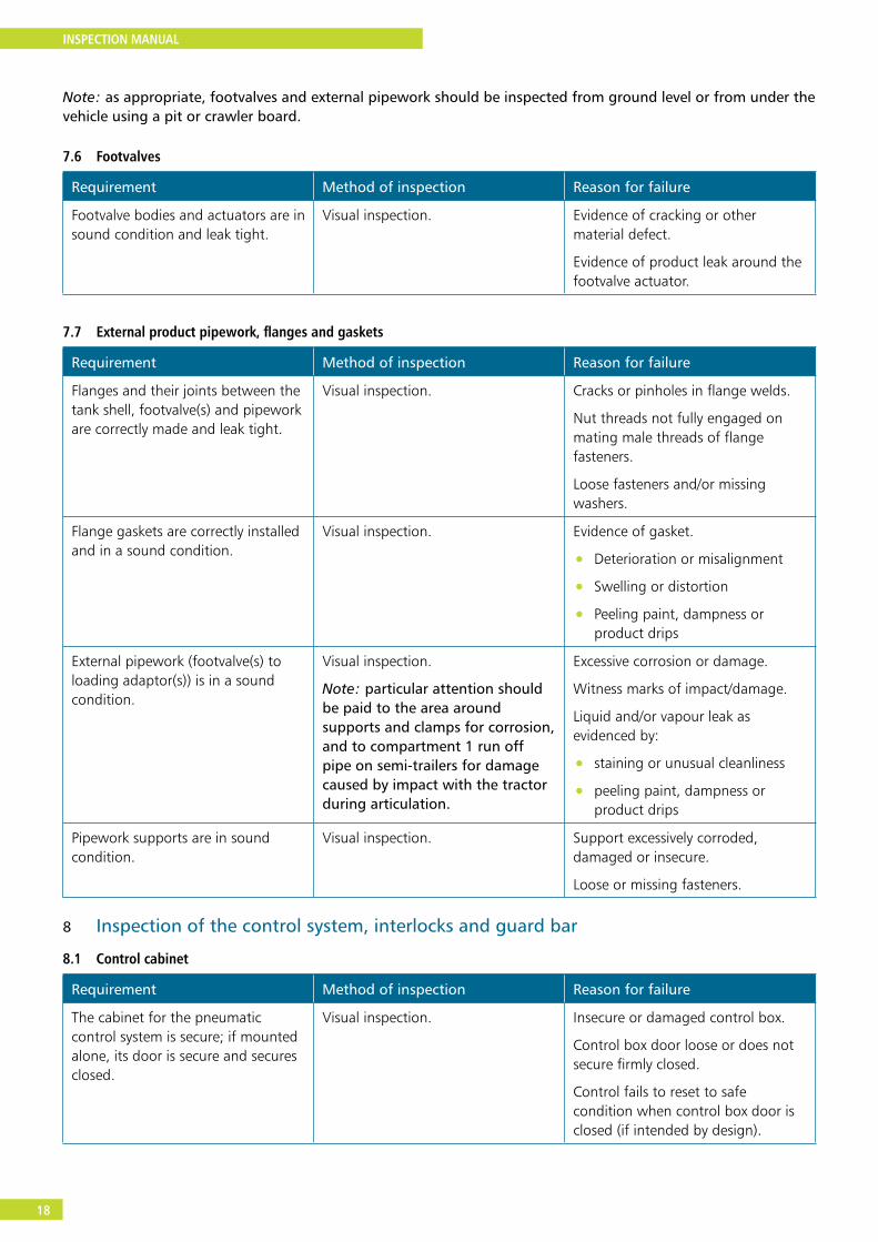
Note: as appropriate, footvalves and external pipework should be inspected from ground level or from under the vehicle using a pit or crawler board.
7.6 Footvalves
Requirement Method of inspection Reason for failure
Footvalve bodies and actuators are in sound condition and leak tight.
Visual inspection. Evidence of cracking or other material defect.
Evidence of product leak around the footvalve actuator.
7.7 External product pipework, flanges and gaskets
Requirement Method of inspection Reason for failure
Flanges and their joints between the tank shell, footvalve(s) and pipework are correctly made and leak tight.
Visual inspection. Cracks or pinholes in flange welds.
Nut threads not fully engaged on mating male threads of flange fasteners.
Loose fasteners and/or missing washers.
Flange gaskets are correctly installed and in a sound condition.
Visual inspection. Evidence of gasket.
• Deterioration or misalignment
• Swelling or distortion
• Peeling paint, dampness or product drips
External pipework (footvalve(s) to loading adaptor(s)) is in a sound condition.
Visual inspection.
Note: particular attention should be paid to the area around supports and clamps for corrosion, and to compartment 1 run off pipe on semi-trailers for damage caused by impact with the tractor during articulation.
Excessive corrosion or damage.
Witness marks of impact/damage.
Liquid and/or vapour leak as evidenced by:
• staining or unusual cleanliness
• peeling paint, dampness or product drips
Pipework supports are in sound condition.
Visual inspection. Support excessively corroded, damaged or insecure.
Loose or missing fasteners.
8 Inspection of the control system, interlocks and guard bar
8.1 Control cabinet
Requirement Method of inspection Reason for failure
The cabinet for the pneumatic control system is secure; if mounted alone, its door is secure and secures closed.
Visual inspection. Insecure or damaged control box.
Control box door loose or does not secure firmly closed.
Control fails to reset to safe condition when control box door is closed (if intended by design).
INSPECTION MANUAL
19
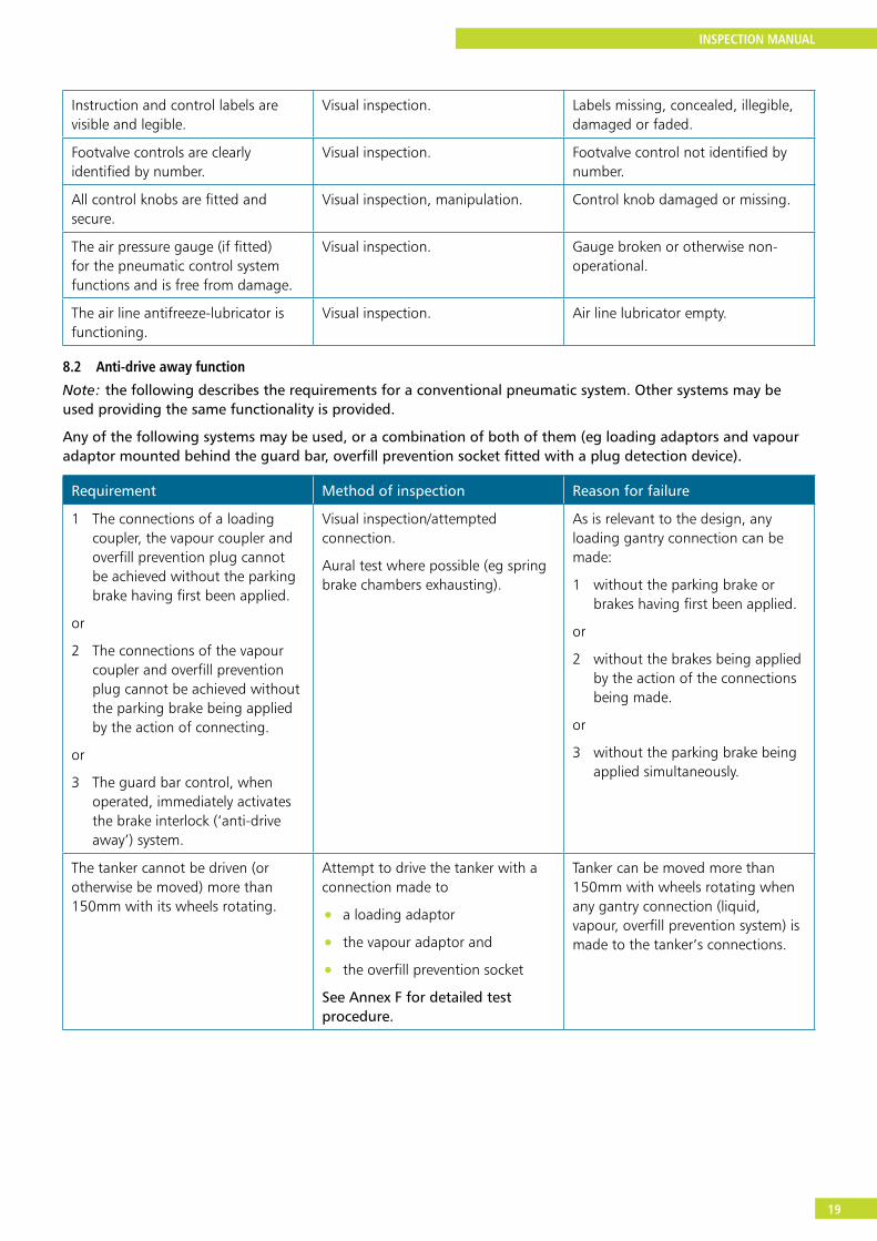
Instruction and control labels are visible and legible.
Visual inspection. Labels missing, concealed, illegible, damaged or faded.
Footvalve controls are clearly identified by number.
Visual inspection. Footvalve control not identified by number.
All control knobs are fitted and secure.
Visual inspection, manipulation. Control knob damaged or missing.
The air pressure gauge (if fitted) for the pneumatic control system functions and is free from damage.
Visual inspection. Gauge broken or otherwise non-operational.
The air line antifreeze-lubricator is functioning.
Visual inspection. Air line lubricator empty.
8.2 Anti-drive away function
Note: the following describes the requirements for a conventional pneumatic system. Other systems may be used providing the same functionality is provided.
Any of the following systems may be used, or a combination of both of them (eg loading adaptors and vapour adaptor mounted behind the guard bar, overfill prevention socket fitted with a plug detection device).
Requirement Method of inspection Reason for failure
1 The connections of a loading coupler, the vapour coupler and overfill prevention plug cannot be achieved without the parking brake having first been applied.
or
2 The connections of the vapour coupler and overfill prevention plug cannot be achieved without the parking brake being applied by the action of connecting.
or
3 The guard bar control, when operated, immediately activates the brake interlock (‘anti-drive away’) system.
Visual inspection/attempted connection.
Aural test where possible (eg spring brake chambers exhausting).
As is relevant to the design, any loading gantry connection can be made:
1 without the parking brake or brakes having first been applied.
or
2 without the brakes being applied by the action of the connections being made.
or
3 without the parking brake being applied simultaneously.
The tanker cannot be driven (or otherwise be moved) more than 150mm with its wheels rotating.
Attempt to drive the tanker with a connection made to
• a loading adaptor
• the vapour adaptor and
• the overfill prevention socket
See Annex F for detailed test procedure.
Tanker can be moved more than 150mm with wheels rotating when any gantry connection (liquid, vapour, overfill prevention system) is made to the tanker’s connections.
INSPECTION MANUAL
20
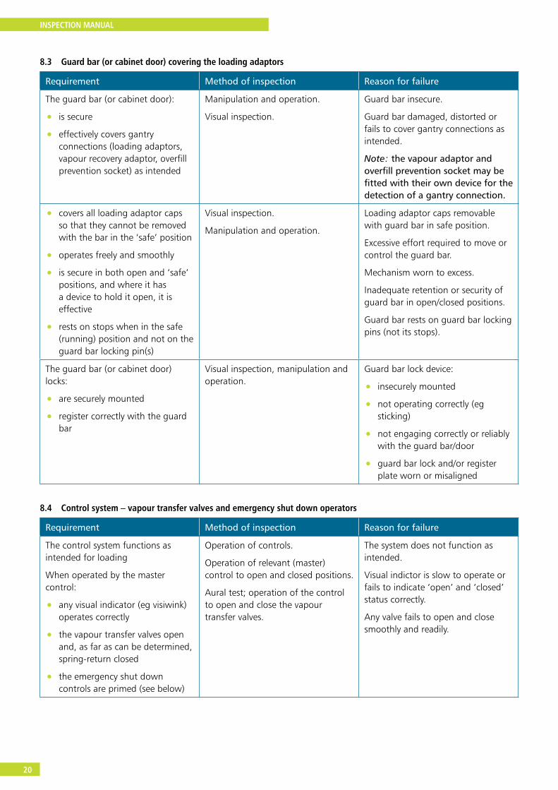
8.3 Guard bar (or cabinet door) covering the loading adaptors
Requirement Method of inspection Reason for failure
The guard bar (or cabinet door):
• is secure
• effectively covers gantry connections (loading adaptors, vapour recovery adaptor, overfill prevention socket) as intended
Manipulation and operation.
Visual inspection.
Guard bar insecure.
Guard bar damaged, distorted or fails to cover gantry connections as intended.
Note: the vapour adaptor and overfill prevention socket may be fitted with their own device for the detection of a gantry connection.
• covers all loading adaptor caps so that they cannot be removed with the bar in the ‘safe’ position
• operates freely and smoothly
• is secure in both open and ‘safe’ positions, and where it has a device to hold it open, it is effective
• rests on stops when in the safe (running) position and not on the guard bar locking pin(s)
Visual inspection.
Manipulation and operation.
Loading adaptor caps removable with guard bar in safe position.
Excessive effort required to move or control the guard bar.
Mechanism worn to excess.
Inadequate retention or security of guard bar in open/closed positions.
Guard bar rests on guard bar locking pins (not its stops).
The guard bar (or cabinet door) locks:
• are securely mounted
• register correctly with the guard bar
Visual inspection, manipulation and operation.
Guard bar lock device:
• insecurely mounted
• not operating correctly (eg sticking)
• not engaging correctly or reliably with the guard bar/door
• guard bar lock and/or register plate worn or misaligned
8.4 Control system – vapour transfer valves and emergency shut down operators
Requirement Method of inspection Reason for failure
The control system functions as intended for loading
When operated by the master control:
• any visual indicator (eg visiwink) operates correctly
• the vapour transfer valves open and, as far as can be determined, spring-return closed
• the emergency shut down controls are primed (see below)
Operation of controls.
Operation of relevant (master) control to open and closed positions.
Aural test; operation of the control to open and close the vapour transfer valves.
The system does not function as intended.
Visual indictor is slow to operate or fails to indicate ‘open’ and ‘closed’ status correctly.
Any valve fails to open and close smoothly and readily.
INSPECTION MANUAL
21
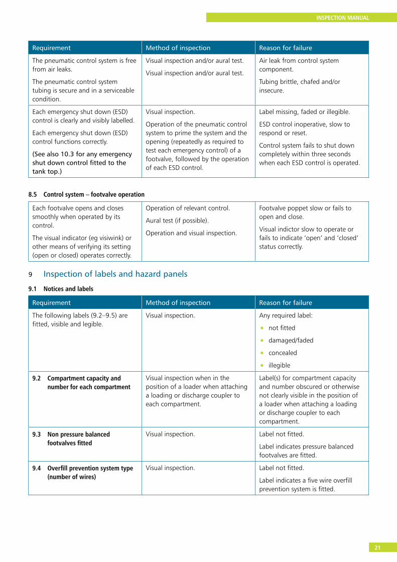
Requirement Method of inspection Reason for failure
The pneumatic control system is free from air leaks.
The pneumatic control system tubing is secure and in a serviceable condition.
Visual inspection and/or aural test.
Visual inspection and/or aural test.
Air leak from control system component.
Tubing brittle, chafed and/or insecure.
Each emergency shut down (ESD) control is clearly and visibly labelled.
Each emergency shut down (ESD) control functions correctly.
(See also 10.3 for any emergency shut down control fitted to the tank top.)
Visual inspection.
Operation of the pneumatic control system to prime the system and the opening (repeatedly as required to test each emergency control) of a footvalve, followed by the operation of each ESD control.
Label missing, faded or illegible.
ESD control inoperative, slow to respond or reset.
Control system fails to shut down completely within three seconds when each ESD control is operated.
8.5 Control system – footvalve operation
Each footvalve opens and closes smoothly when operated by its control.
The visual indicator (eg visiwink) or other means of verifying its setting (open or closed) operates correctly.
Operation of relevant control.
Aural test (if possible).
Operation and visual inspection.
Footvalve poppet slow or fails to open and close.
Visual indictor slow to operate or fails to indicate ‘open’ and ‘closed’ status correctly.
9 Inspection of labels and hazard panels
9.1 Notices and labels
Requirement Method of inspection Reason for failure
The following labels (9.2–9.5) are fitted, visible and legible.
Visual inspection. Any required label:
• not fitted
• damaged/faded
• concealed
• illegible
9.2 Compartment capacity and number for each compartment
Visual inspection when in the position of a loader when attaching a loading or discharge coupler to each compartment.
Label(s) for compartment capacity and number obscured or otherwise not clearly visible in the position of a loader when attaching a loading or discharge coupler to each compartment.
9.3 Non pressure balanced footvalves fitted
Visual inspection. Label not fitted.
Label indicates pressure balanced footvalves are fitted.
9.4 Overfill prevention system type (number of wires)
Visual inspection. Label not fitted.
Label indicates a five wire overfill prevention system is fitted.
INSPECTION MANUAL
22
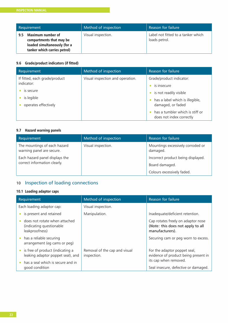
Requirement Method of inspection Reason for failure
9.5 Maximum number of compartments that may be loaded simultaneously (for a tanker which carries petrol)
Visual inspection. Label not fitted to a tanker which loads petrol.
9.6 Grade/product indicators (if fitted)
Requirement Method of inspection Reason for failure
If fitted, each grade/product indicator:
• is secure
• is legible
• operates effectively
Visual inspection and operation. Grade/product indicator:
• is insecure
• is not readily visible
• has a label which is illegible, damaged, or faded
• has a tumbler which is stiff or does not index correctly
9.7 Hazard warning panels
Requirement Method of inspection Reason for failure
The mountings of each hazard warning panel are secure.
Each hazard panel displays the correct information clearly.
Visual inspection. Mountings excessively corroded or damaged.
Incorrect product being displayed.
Board damaged.
Colours excessively faded.
10 Inspection of loading connections
10.1 Loading adaptor caps
Requirement Method of inspection Reason for failure
Each loading adaptor cap:
• is present and retained
• does not rotate when attached (indicating questionable leakproofness)
• has a reliable securing arrangement (eg cams or peg)
Visual inspection.
Manipulation. Inadequate/deficient retention.
Cap rotates freely on adaptor nose (Note: this does not apply to all manufacturers).
Securing cam or peg worn to excess.
• is free of product (indicating a leaking adaptor poppet seal), and
• has a seal which is secure and in good condition
Removal of the cap and visual inspection.
For the adaptor poppet seal, evidence of product being present in its cap when removed.
Seal insecure, defective or damaged.
INSPECTION MANUAL
23
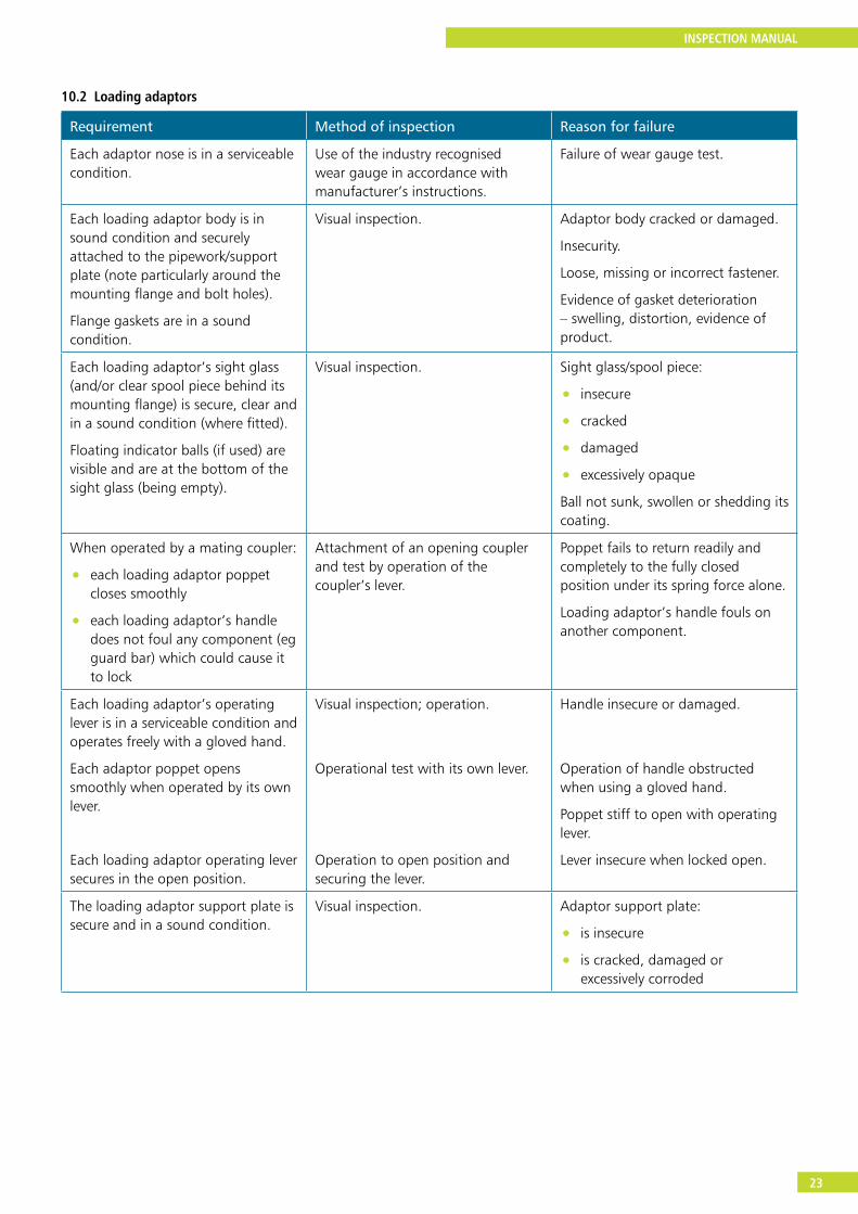
10.2 Loading adaptors
Requirement Method of inspection Reason for failure
Each adaptor nose is in a serviceable condition.
Use of the industry recognised wear gauge in accordance with manufacturer’s instructions.
Failure of wear gauge test.
Each loading adaptor body is in sound condition and securely attached to the pipework/support plate (note particularly around the mounting flange and bolt holes).
Flange gaskets are in a sound condition.
Visual inspection. Adaptor body cracked or damaged.
Insecurity.
Loose, missing or incorrect fastener.
Evidence of gasket deterioration – swelling, distortion, evidence of product.
Each loading adaptor’s sight glass (and/or clear spool piece behind its mounting flange) is secure, clear and in a sound condition (where fitted).
Floating indicator balls (if used) are visible and are at the bottom of the sight glass (being empty).
Visual inspection. Sight glass/spool piece:
• insecure
• cracked
• damaged
• excessively opaque
Ball not sunk, swollen or shedding its coating.
When operated by a mating coupler:
• each loading adaptor poppet closes smoothly
• each loading adaptor’s handle does not foul any component (eg guard bar) which could cause it to lock
Attachment of an opening coupler and test by operation of the coupler’s lever.
Poppet fails to return readily and completely to the fully closed position under its spring force alone.
Loading adaptor’s handle fouls on another component.
Each loading adaptor’s operating lever is in a serviceable condition and operates freely with a gloved hand.
Each adaptor poppet opens smoothly when operated by its own lever.
Each loading adaptor operating lever secures in the open position.
Visual inspection; operation.
Operational test with its own lever.
Operation to open position and securing the lever.
Handle insecure or damaged.
Operation of handle obstructed when using a gloved hand.
Poppet stiff to open with operating lever.
Lever insecure when locked open.
The loading adaptor support plate is secure and in a sound condition.
Visual inspection. Adaptor support plate:
• is insecure
• is cracked, damaged or excessively corroded
INSPECTION MANUAL
24
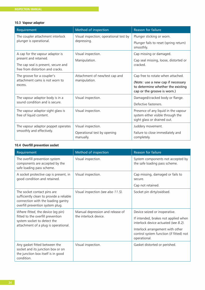
10.3 Vapour adaptor
Requirement Method of inspection Reason for failure
The coupler attachment interlock plunger is operational.
Visual inspection; operational test by depressing.
Plunger sticking or worn.
Plunger fails to reset (spring return) smoothly.
A cap for the vapour adaptor is present and retained.
The cap seal is present, secure and free from distortion and cracks.
Visual inspection.
Manipulation.
Cap missing or damaged.
Cap seal missing, loose, distorted or cracked.
The groove for a coupler’s attachment cams is not worn to excess.
Attachment of new/test cap and manipulation.
Cap free to rotate when attached.
(Note: use a new cap if necessary to determine whether the existing cap or the groove is worn.)
The vapour adaptor body is in a sound condition and is secure.
Visual inspection. Damaged/cracked body or flange.
Defective fasteners.
The vapour adaptor sight glass is free of liquid content.
Visual inspection. Presence of any liquid in the vapour system either visible through the sight glass or drained out.
The vapour adaptor poppet operates smoothly and effectively.
Visual inspection.
Operational test by opening manually.
Juddery movement.
Failure to close immediately and completely.
10.4 Overfill prevention socket
Requirement Method of inspection Reason for failure
The overfill prevention system components are accepted by the safe loading pass scheme.
Visual inspection. System components not accepted by the safe loading pass scheme.
A socket protective cap is present, in good condition and retained.
Visual inspection. Cap missing, damaged or fails to secure.
Cap not retained.
The socket contact pins are sufficiently clean to provide a reliable connection with the loading gantry overfill prevention system plug.
Visual inspection (see also 11.5). Socket pin dirty/oxidised.
Where fitted, the device (eg pin) fitted to the overfill prevention system socket to detect the attachment of a plug is operational.
Manual depression and release of the interlock device.
Device seized or inoperative.
If intended, brakes not applied when interlock device actuated (see 8.2).
Interlock arrangement with other control system function (if fitted) not operational.
Any gasket fitted between the socket and its junction box or on the junction box itself is in good condition.
Visual inspection. Gasket distorted or perished.
INSPECTION MANUAL
25
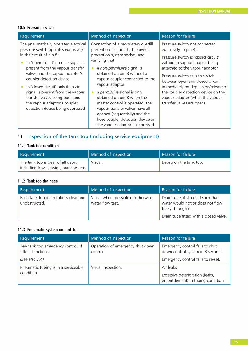
10.5 Pressure switch
Requirement Method of inspection Reason for failure
The pneumatically operated electrical pressure switch operates exclusively in the circuit of pin 8:
• to ‘open circuit’ if no air signal is present from the vapour transfer valves and the vapour adaptor’s coupler detection device
• to ‘closed circuit’ only if an air signal is present from the vapour transfer valves being open and the vapour adaptor’s coupler detection device being depressed
Connection of a proprietary overfill prevention test unit to the overfill prevention system socket, and verifying that:
• a non-permissive signal is obtained on pin 8 without a vapour coupler connected to the vapour adaptor
• a permissive signal is only obtained on pin 8 when the master control is operated, the vapour transfer valves have all opened (sequentially) and the hose coupler detection device on the vapour adaptor is depressed
Pressure switch not connected exclusively to pin 8.
Pressure switch is ‘closed circuit’ without a vapour coupler being attached to the vapour adaptor.
Pressure switch fails to switch between open and closed circuit immediately on depression/release of the coupler detection device on the vapour adaptor (when the vapour transfer valves are open).
11 Inspection of the tank top (including service equipment)
11.1 Tank top condition
Requirement Method of inspection Reason for failure
The tank top is clear of all debris including leaves, twigs, branches etc.
Visual. Debris on the tank top.
11.2 Tank top drainage
Requirement Method of inspection Reason for failure
Each tank top drain tube is clear and unobstructed.
Visual where possible or otherwise water flow test.
Drain tube obstructed such that water would not or does not flow freely through it.
Drain tube fitted with a closed valve.
11.3 Pneumatic system on tank top
Requirement Method of inspection Reason for failure
Any tank top emergency control, if fitted, functions.
(See also 7.4)
Operation of emergency shut down control.
Emergency control fails to shut down control system in 3 seconds.
Emergency control fails to re-set.
Pneumatic tubing is in a serviceable condition.
Visual inspection. Air leaks.
Excessive deterioration (leaks, embrittlement) in tubing condition.
INSPECTION MANUAL
26
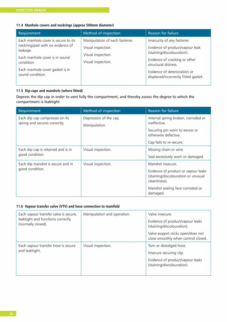
11.4 Manhole covers and neckrings (approx 500mm diameter)
Requirement Method of inspection Reason for failure
Each manhole cover is secure to its neckring/pad with no evidence of leakage.
Each manhole cover is in sound condition.
Each manhole cover gasket is in sound condition.
Manipulation of each fastener.
Visual inspection.
Visual inspection.
Visual inspection.
Insecurity of any fastener.
Evidence of product/vapour leak (staining/discolouration).
Evidence of cracking or other structural distress.
Evidence of deterioration or displaced/incorrectly fitted gasket.
11.5 Dip caps and mandrels (where fitted)
Depress the dip cap in order to vent fully the compartment, and thereby assess the degree to which the compartment is leaktight.
Requirement Method of inspection Reason for failure
Each dip cap compresses on its spring and secures correctly.
Depression of the cap.
Manipulation.
Internal spring broken, corroded or ineffective.
Securing pin worn to excess or otherwise defective.
Cap fails to re-secure.
Each dip cap is retained and is in good condition.
Visual inspection. Missing chain or wire.
Seal excessively worn or damaged.
Each dip mandrel is secure and in good condition.
Visual inspection. Mandrel insecure.
Evidence of product or vapour leaks (staining/discolouration or unusual cleanliness).
Mandrel sealing face corroded or damaged.
11.6 Vapour transfer valve (VTV) and hose connection to manifold
Each vapour transfer valve is secure, leaktight and functions correctly (normally closed).
Manipulation and operation. Valve insecure.
Evidence of product/vapour leaks (staining/discolouration).
Valve poppet sticks open/does not close smoothly when control closed.
Each vapour transfer hose is secure and leaktight.
Visual inspection. Torn or dislodged hose.
Insecure securing clip.
Evidence of product/vapour leaks (staining/discolouration).
INSPECTION MANUAL
27
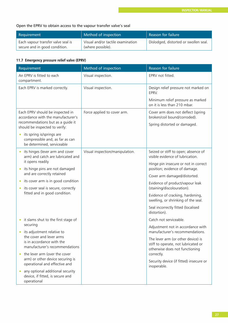
Open the EPRV to obtain access to the vapour transfer valve’s seal
Requirement Method of inspection Reason for failure
Each vapour transfer valve seal is secure and in good condition.
Visual and/or tactile examination (where possible).
Dislodged, distorted or swollen seal.
11.7 Emergency pressure relief valve (EPRV)
Requirement Method of inspection Reason for failure
An EPRV is fitted to each compartment.
Visual inspection. EPRV not fitted.
Each EPRV is marked correctly. Visual inspection. Design relief pressure not marked on EPRV.
Minimum relief pressure as marked on it is less than 210 mbar.
Each EPRV should be inspected in accordance with the manufacturer’s recommendations but as a guide it should be inspected to verify:
• its spring is/springs are compressible and, as far as can be determined, serviceable
Force applied to cover arm. Cover arm does not deflect (spring broken/coil bound/corroded).
Spring distorted or damaged.
• its hinges (lever arm and cover arm) and catch are lubricated and it opens readily
• its hinge pins are not damaged and are correctly retained
• its cover arm is in good condition
• its cover seal is secure, correctly fitted and in good condition.
Visual inspection/manipulation. Seized or stiff to open; absence of visible evidence of lubrication.
Hinge pin insecure or not in correct position; evidence of damage.
Cover arm damaged/distorted.
Evidence of product/vapour leak (staining/discolouration).
Evidence of cracking, hardening, swelling, or shrinking of the seal.
Seal incorrectly fitted (localised distortion).
• it slams shut to the first stage of securing
• its adjustment relative to the cover and lever arms is in accordance with the manufacturer’s recommendations
• the lever arm (over the cover arm) or other device securing is operational and effective and
• any optional additional security device, if fitted, is secure and operational
Catch not serviceable.
Adjustment not in accordance with manufacturer’s recommendations.
The lever arm (or other device) is stiff to operate, not lubricated or otherwise does not functioning correctly.
Security device (if fitted) insecure or inoperable.
INSPECTION MANUAL
28
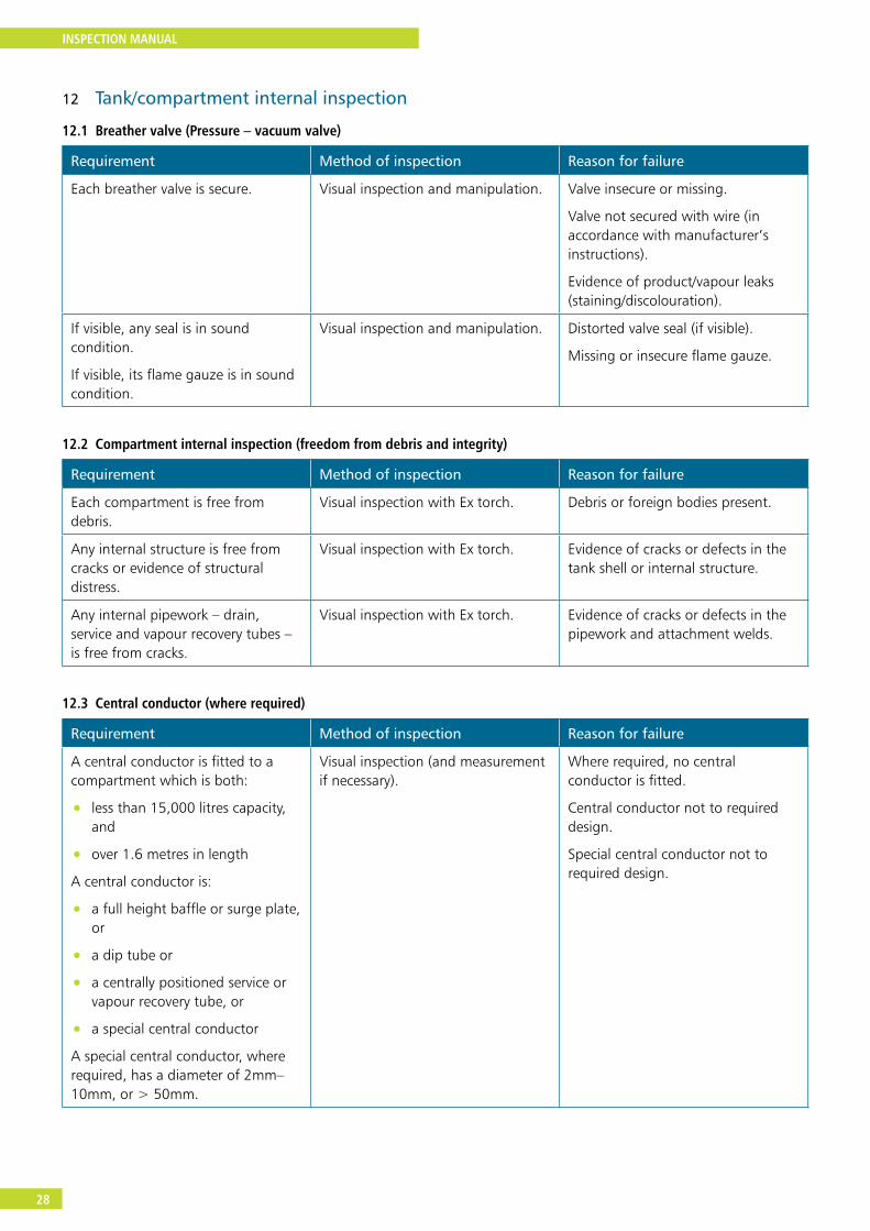
12 Tank/compartment internal inspection
12.1 Breather valve (Pressure – vacuum valve)
Requirement Method of inspection Reason for failure
Each breather valve is secure. Visual inspection and manipulation. Valve insecure or missing.
Valve not secured with wire (in accordance with manufacturer’s instructions).
Evidence of product/vapour leaks (staining/discolouration).
If visible, any seal is in sound condition.
If visible, its flame gauze is in sound condition.
Visual inspection and manipulation. Distorted valve seal (if visible).
Missing or insecure flame gauze.
12.2 Compartment internal inspection (freedom from debris and integrity)
Requirement Method of inspection Reason for failure
Each compartment is free from debris.
Visual inspection with Ex torch. Debris or foreign bodies present.
Any internal structure is free from cracks or evidence of structural distress.
Visual inspection with Ex torch. Evidence of cracks or defects in the tank shell or internal structure.
Any internal pipework – drain, service and vapour recovery tubes – is free from cracks.
Visual inspection with Ex torch. Evidence of cracks or defects in the pipework and attachment welds.
12.3 Central conductor (where required)
Requirement Method of inspection Reason for failure
A central conductor is fitted to a compartment which is both:
• less than 15,000 litres capacity, and
• over 1.6 metres in length
A central conductor is:
• a full height baffle or surge plate, or
• a dip tube or
• a centrally positioned service or vapour recovery tube, or
• a special central conductor
A special central conductor, where required, has a diameter of 2mm–10mm, or > 50mm.
Visual inspection (and measurement if necessary).
Where required, no central conductor is fitted.
Central conductor not to required design.
Special central conductor not to required design.

INSPECTION MANUAL
29
Requirement Method of inspection Reason for failure
Any dip tube/central conductor fitted is secure.
Visual inspection and manipulation. Dip/other tube insecure to its top mounting.
Central conductor cable/wire insecure to its top or bottom anchorage or broken.
Electrical continuity of less than 10 ohms exists between an earth pin or the tank shell and any central conductor or dip tube fitted.
Use of an Ex certified continuity meter.
Resistance greater than 10 ohms.
12.4 Footvalve installation/deflector plate
Requirement Method of inspection Reason for failure
The installation of each footvalve is such that incoming flow of product through it when loading is directed along the tank floor, ie each footvalve is:
• either mounted in a sump (with its bonnet protruding though a close-fitting cut out in the floor of the tank shell), or
• fitted with a deflector plate which is securely attached to the tank shell
Visual inspection. Footvalve neither fitted in a sump nor with a deflector plate.
Deflector plate insecure.
12.5 Overfill prevention system sensors
Requirement Method of inspection Reason for failure
Each overfill prevention sensor housing is secure to the manhole cover.
Manipulation. Insecure housing.
Securing ring or tube loose.
Each overfill prevention sensor is secure in its housing.
Manipulation where possible. Sensor loose.
The setting of each overfill prevention sensor is secured by wire and recognised lead seal in accordance with Annex G.
Visual inspection. Lead seal not identifiable or missing.
Wiring insecure or not in accordance with Annex G for the design fitted.
Each overfill prevention sensor functions correctly (‘wet test’).
Use of a proprietary test kit to carry out a wet test with a beaker of liquid on each sensor.
(Use aviation fuel when testing aviation tankers).
Sensor fails to respond to liquid as intended.
INSPECTION MANUAL
30
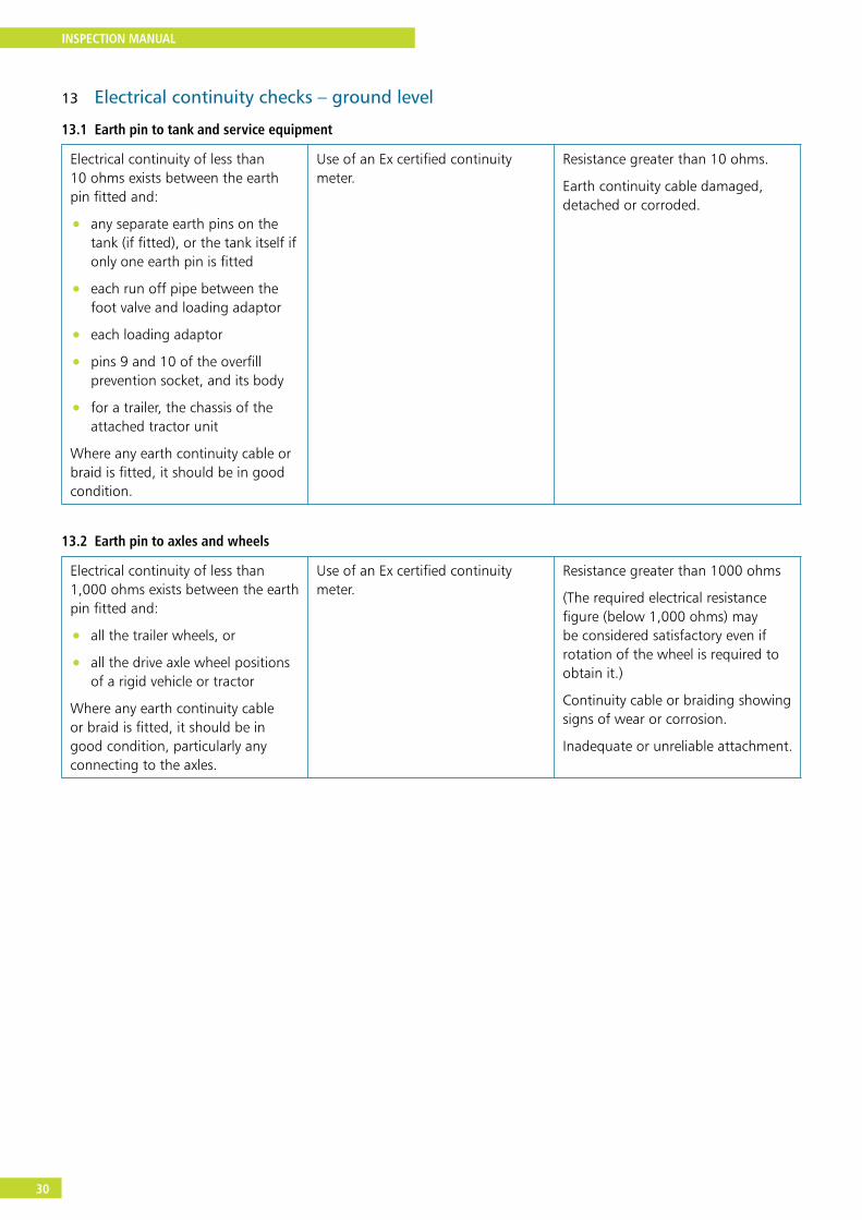
13 Electrical continuity checks – ground level
13.1 Earth pin to tank and service equipment
Electrical continuity of less than 10 ohms exists between the earth pin fitted and:
• any separate earth pins on the tank (if fitted), or the tank itself if only one earth pin is fitted
• each run off pipe between the foot valve and loading adaptor
• each loading adaptor
• pins 9 and 10 of the overfill prevention socket, and its body
• for a trailer, the chassis of the attached tractor unit
Where any earth continuity cable or braid is fitted, it should be in good condition.
Use of an Ex certified continuity meter.
Resistance greater than 10 ohms.
Earth continuity cable damaged, detached or corroded.
13.2 Earth pin to axles and wheels
Electrical continuity of less than 1,000 ohms exists between the earth pin fitted and:
• all the trailer wheels, or
• all the drive axle wheel positions of a rigid vehicle or tractor
Where any earth continuity cable or braid is fitted, it should be in good condition, particularly any connecting to the axles.
Use of an Ex certified continuity meter.
Resistance greater than 1000 ohms
(The required electrical resistance figure (below 1,000 ohms) may be considered satisfactory even if rotation of the wheel is required to obtain it.)
Continuity cable or braiding showing signs of wear or corrosion.
Inadequate or unreliable attachment.
INSPECTION MANUAL
31
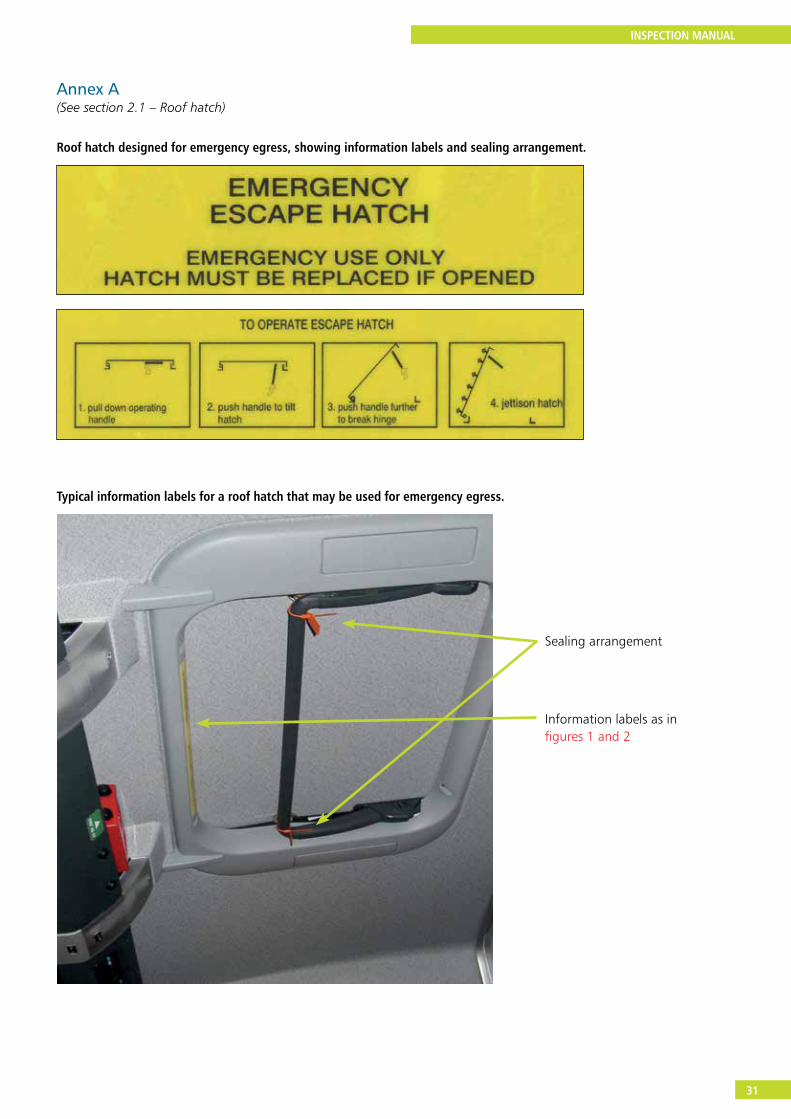
Annex A(See section 2.1 – Roof hatch)
Roof hatch designed for emergency egress, showing information labels and sealing arrangement.
Typical information labels for a roof hatch that may be used for emergency egress.
Information labels as in figures 1 and 2
Sealing arrangement
INSPECTION MANUAL
32
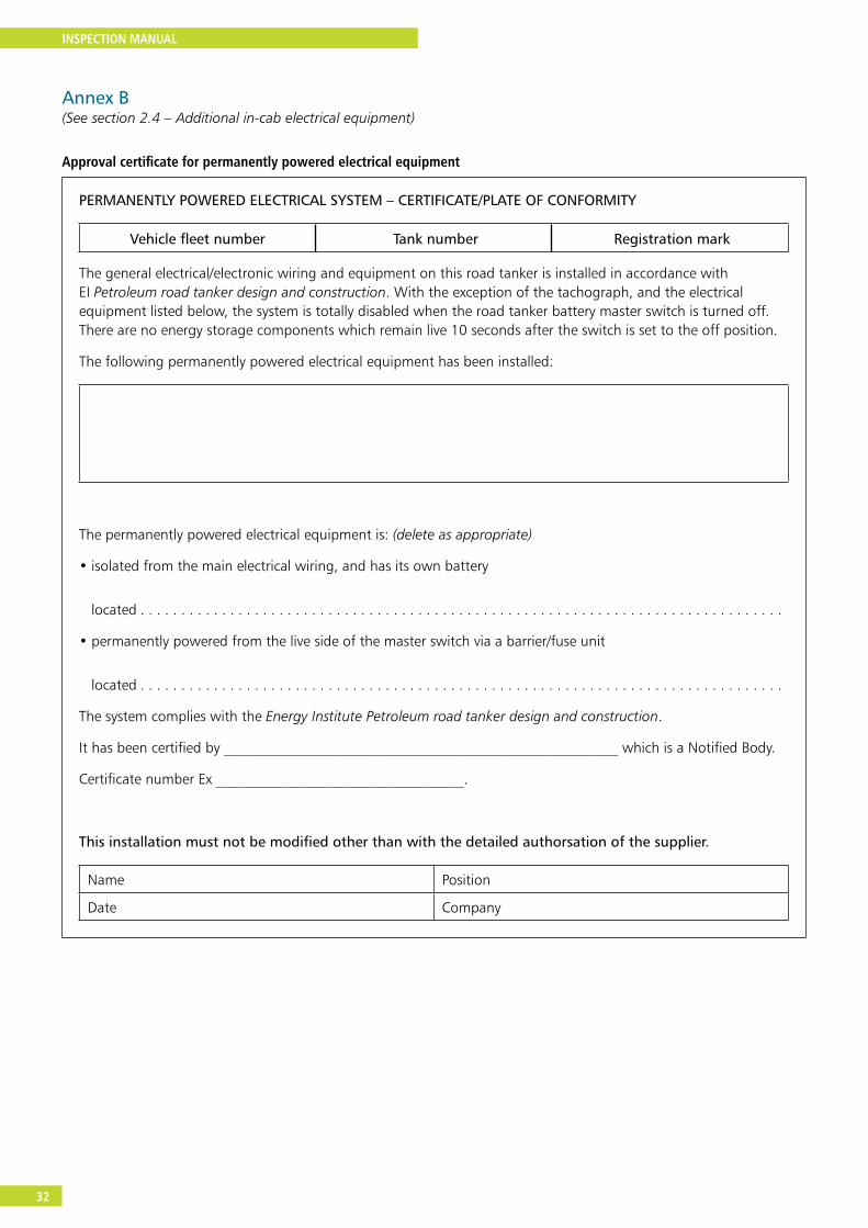
Annex B(See section 2.4 – Additional in-cab electrical equipment)
Approval certificate for permanently powered electrical equipment
PERMANENTLY POWERED ELECTRICAL SYSTEM – CERTIFICATE/PLATE OF CONFORMITY
Vehicle fleet number Tank number Registration mark
The general electrical/electronic wiring and equipment on this road tanker is installed in accordance with EI Petroleum road tanker design and construction. With the exception of the tachograph, and the electrical equipment listed below, the system is totally disabled when the road tanker battery master switch is turned off. There are no energy storage components which remain live 10 seconds after the switch is set to the off position.
The following permanently powered electrical equipment has been installed:
The permanently powered electrical equipment is: (delete as appropriate)
• isolated from the main electrical wiring, and has its own battery
located . . . . . . . . . . . . . . . . . . . . . . . . . . . . . . . . . . . . . . . . . . . . . . . . . . . . . . . . . . . . . . . . . . . . . . . . . . . . . . .
• permanently powered from the live side of the master switch via a barrier/fuse unit
located . . . . . . . . . . . . . . . . . . . . . . . . . . . . . . . . . . . . . . . . . . . . . . . . . . . . . . . . . . . . . . . . . . . . . . . . . . . . . . .
The system complies with the Energy Institute Petroleum road tanker design and construction.
It has been certified by ______________________________________________________ which is a Notified Body.
Certificate number Ex __________________________________.
This installation must not be modified other than with the detailed authorsation of the supplier.
Name Position
Date Company
INSPECTION MANUAL
33
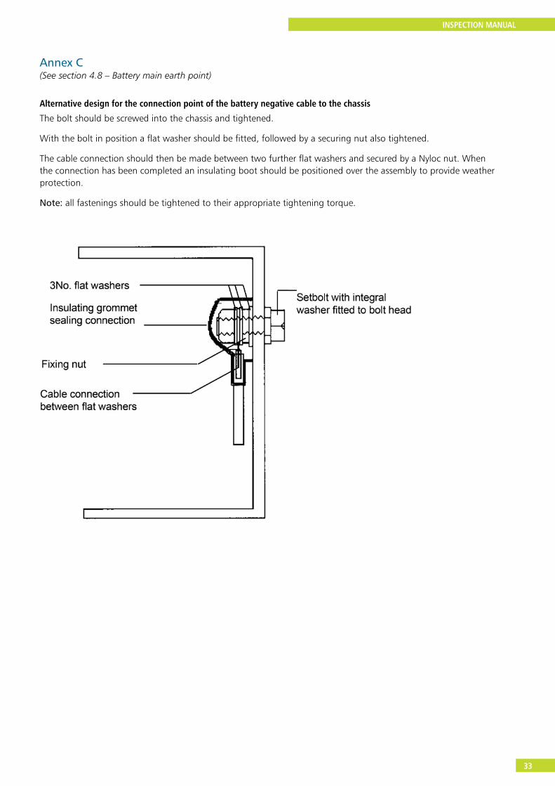
Annex C(See section 4.8 – Battery main earth point)
Alternative design for the connection point of the battery negative cable to the chassis
The bolt should be screwed into the chassis and tightened.
With the bolt in position a flat washer should be fitted, followed by a securing nut also tightened.
The cable connection should then be made between two further flat washers and secured by a Nyloc nut. When the connection has been completed an insulating boot should be positioned over the assembly to provide weather protection.
Note: all fastenings should be tightened to their appropriate tightening torque.
INSPECTION MANUAL
34
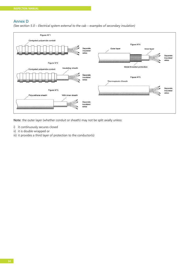
Annex D(See section 5.0 – Electrical system external to the cab – examples of secondary insulation)
Note: the outer layer (whether conduit or sheath) may not be split axially unless:
i) it continuously secures closedii) it is double wrapped or iii) it provides a third layer of protection to the conductor(s)

INSPECTION MANUAL
35
Annex E(See section 5.2 – Repairs to mudwings of non metallic material)
To be advised
INSPECTION MANUAL
36
Annex F(See section 8.2 – Anti-drive away function test)
Note: this test procedure has been developed to take account of changes in braking systems of some articulated vehicles where the practice of using the service line to assist the parking brake can result in the interlock being ineffective temporarily as the park brake control is released.
Test procedure
The operation of the interlock arrangement on all rigid vehicles and semi-trailers should be checked as follows.
1 Park the tanker in a suitable place, with at least 5 metres clear space in front.
2 With the vehicle park brake applied, build up the vehicle air system’s pressure to its maximum.
3 Lift the interlock bar up so that it is in the fully raised position, or attach a dummy connection to the vapour adaptor and overfill prevention socket in turn if not mounted behind the bar.
Note: each should be tested separately if not behind the interlock bar.
4 Return to the cab and after checking that there is nothing in the path of the vehicle, quickly release the park brake and attempt to drive forward.
Note: this needs to be done quickly to replicate a known possible fault condition.
5 If it is possible to move the vehicle more than 150mm (6 inches) forward with the wheels rotating then the vehicle (rigid, tractor or semi-trailer) should not be issued with a Safe Loading Pass.
After conducting the test, re-apply the park brake, remove any dummy connections to the vapour adaptor and overfill prevention socket, and lower the interlock bar.
INSPECTION MANUAL
37
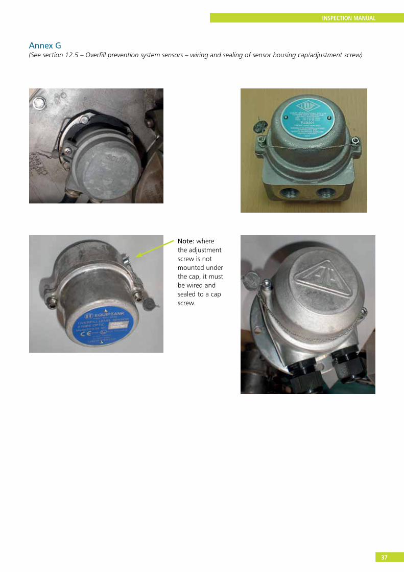
Annex G(See section 12.5 – Overfill prevention system sensors – wiring and sealing of sensor housing cap/adjustment screw)
Note: where the adjustment screw is not mounted under the cap, it must be wired and sealed to a cap screw.

INSPECTION MANUAL
38
Annex H(See Inspection forms – rigid tanker, tractor, trailer)
The full and current version of the forms are available at www.fta.co.uk

INSPECTION MANUAL
39

FOR MORE INFORMATION WEBSITE: www.fta.co.uk/slps EMAIL: [email protected] 05.15/ST