Safe Automotive soFtware architEcture (SAFE)
21
SAFE – an ITEA2 project D55c 2014 The SAFE Consortium 1 (21) Contract number: ITEA2 – 10039 Safe Automotive soFtware architEcture (SAFE) ITEA Roadmap application domains: Major: Services, Systems & Software Creation Minor: Society ITEA Roadmap technology categories: Major: Systems Engineering & Software Engineering Minor 1: Engineering Process Support WP 5, WT 5.5 Deliverable D55c: Electronic Steering Column Lock Use Case. Due date of deliverable: 30/06/2014 Actual submission date: 30/06/2014 Start date of the project: 01/07/2011 Duration: 36 months Project coordinator name: Stefan Voget Organization name of lead contractor for this deliverable: Valeo Editor: F. Meurville Reviewers: C. Ainhauser; L. Quéran
Transcript of Safe Automotive soFtware architEcture (SAFE)

SAFE – an ITEA2 project D55c
2014 The SAFE Consortium 1 (21)
Contract number: ITEA2 – 10039
Safe Automotive soFtware architEcture (SAFE)
ITEA Roadmap application domains:
Major: Services, Systems & Software Creation
Minor: Society
ITEA Roadmap technology categories:
Major: Systems Engineering & Software Engineering
Minor 1: Engineering Process Support
WP 5, WT 5.5
Deliverable D55c:
Electronic Steering Column Lock Use Case.
Due date of deliverable: 30/06/2014
Actual submission date: 30/06/2014
Start date of the project: 01/07/2011 Duration: 36 months
Project coordinator name: Stefan Voget
Organization name of lead contractor for this deliverable: Valeo
Editor: F. Meurville
Reviewers: C. Ainhauser; L. Quéran

SAFE – an ITEA2 project D55c
2014 The SAFE Consortium 2 (21)
Version Date Reason
0.1 2014-06-04 Initialization of document
0.5 2014-06-10 Ready for review
0.6 2014-06-12 First comments from Loic
0.7 2014-06-13 First corrections added
0.8 2014-06-13 Second set of correction added after meeting with Loic
0.9 2014-06-13 Ready for final review
0.95 2014-06-27 Integration of Christoph comments ; Ready for release
1.0 2014-06-27 Release

SAFE – an ITEA2 project D55c
2014 The SAFE Consortium 3 (21)
1 Table of contents & figures
1 Table of contents & figures ......................................................................................................................................... 3
2 Executive Summary .................................................................................................................................................... 4
3 Electronic Steering Column Lock (ESCL) Use Case .................................................................................................. 5
3.1 Use case context................................................................................................................................................ 5
3.2 Use case general description. ............................................................................................................................ 6
3.3 Motivation and Argumentation ........................................................................................................................... 7
3.3.1 Development approach before SAFE ........................................................................................................ 7
3.3.2 New approach ........................................................................................................................................... 7
3.3.3 Benefits / drawbacks of the new approach compared to the current approach ......................................... 8
3.3.4 Evaluation phase ....................................................................................................................................... 8
3.4 Implementation .................................................................................................................................................. 9
3.4.1 Dependencies ........................................................................................................................................... 9
3.4.2 Coverage Plan ........................................................................................................................................... 9
3.4.3 Final implementation state of the evaluator ............................................................................................... 9
4 Evaluation Results .................................................................................................................................................... 12
4.1 Evaluation results for sub-Work Product WP55_1 and more especially the Metrics plug-in ............................ 12
4.1.1 Fulfillment of WP 3/4/6 requirements in WP55_1 context ....................................................................... 12
4.1.2 Evaluation of WP 3/4/6 requirements in WP55_1 context ....................................................................... 16
4.2 Evaluation results for sub-Work Product WP55_2 and more especially the Requirements plug-in .................. 17
4.2.1 Fulfillment of WP 3/4/6 requirements in WP55_2 context ....................................................................... 17
4.2.2 Evaluation of WP 3/4/6 requirements in WP55_2 context ....................................................................... 18
5 Conclusion ................................................................................................................................................................ 19
6 References ............................................................................................................................................................... 20
7 Acknowledgments ..................................................................................................................................................... 21
Figure 1 : System representation with Safety Designer. ...................................................................................................... 6
Figure 2 : Basic illustration of the new approach. ................................................................................................................ 7
Figure 3. Example of simulation in Safety Designer with fault injection ............................................................................... 9
Figure 4.Example of ISO26262 Part 5 Annex E rebuilt in Safety Designer at an higher abstraction level. ........................ 10
Figure 5. Synthesis of architectural metrics results in Safety Designer. ............................................................................ 11
Figure 6. Example of safety goal expression with its requirements derived ...................................................................... 11
Table 1. Fulfillment of WT322 relevant requirements in WP55_1 context ......................................................................... 13
Table 2. Fulfillment of WT331 relevant requirements in WP55_1 context ......................................................................... 15
Table 3. Qualitative evaluation of WP55_1 ........................................................................................................................ 16
Table 4. Fulfillment of WT312 relevant requirements in WP55_2 context ......................................................................... 17
Table 5. Qualitative evaluation of WP55_2 ........................................................................................................................ 18
Table 6. Quantified benefit of SAFE versus development step ......................................................................................... 19
Table 7. Quantified benefit of SAFE versus engineering domain ...................................................................................... 19
SAFE – an ITEA2 project D55c
2014 The SAFE Consortium 4 (21)
2 Executive Summary
The objective of WP5 (see SAFE FPP [3]) is a) to refine requirements for, b) provide feedback on and c) evaluate methods and tools developed in WP3 and WP4 as well as methodologies and application rules defined in WP6 in context of realistic industrial case studies. Best practices established during the evaluation will be documented.
Therefore, Valeo has proposed, for use case, an existing product dealing with ISO26262 compliancy to demonstrate the previous objective.

SAFE – an ITEA2 project D55c
2014 The SAFE Consortium 5 (21)
3 Electronic Steering Column Lock (ESCL) Use Case
3.1 Use case context.
The Valeo industrial use case and related scenarios will target evaluation and demonstration of progress beyond current practices regarding:
Requirement management
Insure a seamless handling of safety requirements within overall requirement management providing relevant coverage and impact synthesis for the safety case documentation. Avoid inefficiency of document-oriented traceability by introducing model-centric requirement management in design activities (refer to dysfunctional modelling improvements).
Continuous modelling
By merging or at least coupling functional and dysfunctional modelling while sharing common abstraction levels, consistency of the overall safety concept is achievable with an optimized effort. Furthermore, sharing the same ground between designers and safety experts insures consistency during the complete lifecycle and, especially, while iterating the different increments or during maintenance.
Automated safety analysis
Due to the sound basis of functional / dysfunctional modelling, it will be possible to capture elements and feed inputs in FMEA and FTA, thus avoiding double filling and synchronization issues between design and safety teams. Dysfunctional modelling will allow some automatic computation in the safety analysis, allowing safety experts to focus on critical topics. Above improvement on the coupling with design, lowering the effort to critical issues shall also allow to be more reactive during increments.
Continuous verification
Final objective of the whole set of improvements is to allow continuous verification while walking through the development cycle and involving the different development teams.
Qualitative and quantitative measures:
- Safety concept consistency insured throughout relevant abstraction levels
- Efficient modelling mixing functional and dysfunctional focuses
- Formal exchange with OEM and subcontractor organizations based on models
- Consistency of safety analyses done at the different levels (hierarchical links, impacts)
- Efficiency of automated safety analyses realization and maintenance
- Consistency of safety traceability with overall traceability
- Efficiency of model centric requirement management
- Efficiency of safety products developments by tight coupling of designers with safety experts sharing the same technical ground

SAFE – an ITEA2 project D55c
2014 The SAFE Consortium 6 (21)
3.2 Use case general description.
The Valeo industrial use case is an Electronic Steering Column Lock (ESCL) system as represented below:
Figure 1 : System representation with Safety Designer.
The system is made of 4 wheel sensors, 3 ECUs (ABS, PSE, and ESCL) connected and communicating together via LIN or CAN bus, and one electrical actuator.
The main function of interest here for this system is to lock and to unlock the steering column on request.
Lock is needed to ensure anti-theft function when occupants are leaving the vehicle. Unlock is needed to be able to turn steering column when driving the vehicle in normal
conditions.
The corresponding safety goal resulting from hazard & risk analysis is SG05: The system shall not lock the steering column lock when vehicle speed is higher than 4 km/h [ASIL D]
The main goal of this work is to:
model our use case using the AltaRica dataflow language in the Safety Designer environment,
simulate the model and inject fault to see if the modeling is behaving as in the reality,
generate automatically safety analyses,
and calculate automatically the architectural metrics (Single-Point Fault and Latent Fault Metrics) and the Probabilistic Metric for random Hardware Failures (PMHF)
Also of interest but with less intensity, to complete the safety concept, requirements would be imported in Safety Designer, linked together, allocated to model elements and if possible retranslated in formal language corresponding to AltaRica code.

SAFE – an ITEA2 project D55c
2014 The SAFE Consortium 7 (21)
3.3 Motivation and Argumentation
3.3.1 Development approach before SAFE
Today, the use case is not performed in a seamless process.
Depending on the activities to be performed, many different tools (Visio, Atego studio, Excel, Word, Item Toolkit, Reqtify mainly) are used and the exchange of data between the different tools is not automatic and, most of the time, fastidious and error prone. Moreover, when a modification is done somewhere in the use case, the completeness and the correctness of its propagation is difficult to ensure.
Most of safety analyses are done manually using Excel tables and Item toolkit for FTA. The link between qualitative and quantitative analyses is manual as well as the link between inductive and deductive analyses methods.
Therefore people in charge of building of the safety concept spend more time on documents generation and update than really on the safety concept itself.
3.3.2 New approach
At the time when we started the use case the SAFE platform was not yet implemented. Therefore it was decided to use the Safety Designer / Aralia Fault Tree tools from Dassault Systèmes because the main topic of interest for Valeo at that time was the automatic generation of safety analyses from models.
A partial illustration of the new approach is provided in the Figure 2 below.
Basic idea is first to define locally the “normal” and “abnormal” behavior of each block, a block representing most of the time one functionality (e.g. a power supply unit which has to provide a given voltage).
Then in a second step the different blocks are connected together and synchronized.
In a third step depending on the model construct and objectives of the analysis (e.g. the order of failures has an importance) cut sets or combination of sequences, leading to the violation of a considered safety goal, are automatically generated.
Figure 2 : Basic illustration of the new approach.
In a fourth step, the combination of sequences can be used by the new Metrics plug-in developed by Dassault Systèmes in Safety Designer to calculate the architectural metrics.
In a fifth step, cut sets or combination of sequences can be also exported to Aralia Fault Tree analyzer in order to calculate the PMHF.
Finally safety requirements would be imported into Safety Designer and allocated to the relevant elements of the model.
SAFE – an ITEA2 project D55c
2014 The SAFE Consortium 8 (21)
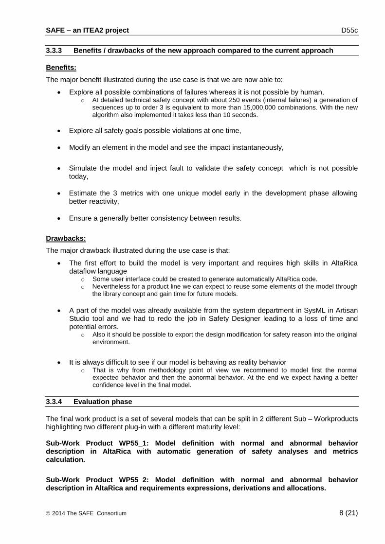
3.3.3 Benefits / drawbacks of the new approach compared to the current approach
Benefits:
The major benefit illustrated during the use case is that we are now able to:
Explore all possible combinations of failures whereas it is not possible by human, o At detailed technical safety concept with about 250 events (internal failures) a generation of
sequences up to order 3 is equivalent to more than 15,000,000 combinations. With the new algorithm also implemented it takes less than 10 seconds.
Explore all safety goals possible violations at one time,
Modify an element in the model and see the impact instantaneously,
Simulate the model and inject fault to validate the safety concept which is not possible today,
Estimate the 3 metrics with one unique model early in the development phase allowing better reactivity,
Ensure a generally better consistency between results.
Drawbacks:
The major drawback illustrated during the use case is that:
The first effort to build the model is very important and requires high skills in AltaRica dataflow language
o Some user interface could be created to generate automatically AltaRica code. o Nevertheless for a product line we can expect to reuse some elements of the model through
the library concept and gain time for future models.
A part of the model was already available from the system department in SysML in Artisan Studio tool and we had to redo the job in Safety Designer leading to a loss of time and potential errors.
o Also it should be possible to export the design modification for safety reason into the original environment.
It is always difficult to see if our model is behaving as reality behavior o That is why from methodology point of view we recommend to model first the normal
expected behavior and then the abnormal behavior. At the end we expect having a better confidence level in the final model.
3.3.4 Evaluation phase
The final work product is a set of several models that can be split in 2 different Sub – Workproducts highlighting two different plug-in with a different maturity level: Sub-Work Product WP55_1: Model definition with normal and abnormal behavior description in AltaRica with automatic generation of safety analyses and metrics calculation.
Sub-Work Product WP55_2: Model definition with normal and abnormal behavior description in AltaRica and requirements expressions, derivations and allocations.

SAFE – an ITEA2 project D55c
2014 The SAFE Consortium 9 (21)
3.4 Implementation
3.4.1 Dependencies
The development of the WT55 implies the following dependencies on the project Work task:
WT312 : Safety Requirements Expression WT322 : Hardware Modeling WT331 : Failure and cut sets analyses
3.4.2 Coverage Plan
The evaluator will cover:
System modeling with normal and abnormal behavior at different abstraction levels,
Automatic generation of safety analyses with metrics quantifications,
Safety goals and safety requirements expression with informal and formal notation,
Functional safety concept and technical safety concept.
3.4.3 Final implementation state of the evaluator
The evaluator is today made of several models.
1. An initial model was build focusing only on the abnormal behavior and it appeared that it only addressed one safety goal and potentially the reuse of this model for future similar projects was limited. Moreover it was difficult to demonstrate that the expected model behavior was representative of the real behavior.
2. Therefore a second model was rebuilt focusing more at first on the normal behavior and
then on abnormal behavior. This model is much more complex, because the communication protocol between the PSE and the ESCL are represented, but it is then easier for system engineer to verify the reality of the behavior using the simulation capability of Safety Designer as shown in Figure 3. Moreover this model can address several safety goals (2 other safety goals were therefore added in our use case for demonstration capability) at one time and can be reused easily in other similar projects using the library concept.
Figure 3. Example of simulation in Safety Designer with fault injection

SAFE – an ITEA2 project D55c
2014 The SAFE Consortium 10 (21)
This second model is now our reference. Combinations of sequences can also be generated even if the model is complex with numerous loops thanks to the new algorithm developed by Dassault Systèmes. Moreover the combinations of sequences can be exported in Aralia Fault Tree Analyzer allowing the calculation of the PMFH.
Our main goal for the evaluator was also to validate the automatic calculation of architectural metrics from sequences generation. But it appeared quickly that the ESCL model built with AltaRica was more refined than what has been done with the classical approach before SAFE. Therefore we had not enough data to validate the Metrics plug-in with our complete ESCL model.
3. Therefore a third model was build from the well known example of ISO26262 Part 5 Annex E [7] as shown in Figure 4. The advantage is that this example is not so complex and that results for architectural metrics are fully available to verify and demonstrate the correctness of the new plug-in in Safety Designer. Nevertheless it was needed to rework the example at a higher abstraction level because it is not easily feasible to model the detailed behavior of hardware parts with AltaRica. Moreover it appears quickly that the method to calculate the latent fault metrics in an automatic ways was not so easy and that it was necessary to model also the driver and its perception of events.
Figure 4.Example of ISO26262 Part 5 Annex E rebuilt in Safety Designer at a higher abstraction level.
This third model linked with FMEA manual results performed at hardware part level has permitted to validate the Metrics plug-in against the results expected in the ISO26262 Part 5 Annex E [7].
A synthesis of results from the Safety Designer tool is shown in the Figure 5.

SAFE – an ITEA2 project D55c
2014 The SAFE Consortium 11 (21)
Figure 5. Synthesis of architectural metrics results in Safety Designer.
At the time when we released this deliverable, the Metrics plug-in was not tested on our model of reference because some important rework was necessary to model the driver perception and it was not possible in the time slot.
4. In parallel to the automatic generation of combinations of sequence with the calculation of metrics safety goals and functional safety requirements were imported in the Safety Designer tool from CSV format, then linked together using derivation links and allocated to elements from the model as shown in for SG05.
Figure 6. Example of safety goal expression with its requirements derived
A first tentative of translation of safety goals expressions from informal into formal was performed with success. It is theoretically also possible for other kind of safety requirements but would require also reworking our model of reference and some of the already existing informal requirements. Therefore the experiment with formal requirements ended here because it is a huge topic at its own and would require much more time.

SAFE – an ITEA2 project D55c
2014 The SAFE Consortium 12 (21)
4 Evaluation Results
As in our case two separate sub–work products with different goals are clearly defined it would lead to separate evaluations.
4.1 Evaluation results for sub-Work Product WP55_1 and more especially the Metrics plug-in
4.1.1 Fulfillment of WP 3/4/6 requirements in WP55_1 context
This section shall summarize the fulfillment of requirements assessed in work task 5.5 that are relevant for the sub-work Product WP55_1.
As the SAFE technology platform was not available at the time when it was decided to build our use case with Safety Designer/Aralia Fault Tree Analyzer tools from Dassault Systèmes and therefore in the following evaluation we would refer to it instead of SAFE.
WT55_REQ_2: The Safety Designer tool shall demonstrate the capability to capture the hardware component and failure rate of the use case.
Identifier Requirement Qualitative Statement
Rationale
WT322_REQ_18 The Safe Meta model shall allow to describe
different Failure Modes of the hardware components
Complete Using AltaRica language
WT322_REQ_19
The Safe Meta model shall allow defining documentation for the potential cause
(temperature, vibrations, EMC …) of each failure mode.
Partly fulfilled Reference of relevant documents could be added in comments
WT322_REQ_21
The Safe Meta model shall capture the characterization and the documentation of each failure mode for each dedicated safety goal as
safe fault (no violation of safety goal even if combination with another independent failure),
single-point (violation of safety goal with no safety mechanism for mitigation), residual fault (violation of safety goal with safety mechanism but not covering this failure mode) or multi-point fault (violation of safety goal in combination with another independent failure even if protected by
safety mechanism) latent for not detected or perceived for not detected by perceived and multi-point fault detected (with no violation of
safety goal in combination with another independent failure covered by a safety
mechanism). Failure mode can have several characterizations (Residual and Latent for
example).
Complete
Output provided by the Metrics plug-in permits to
tag the fault for each safety goal.
WT322_REQ_22
The Safe Meta model shall deduced from the characterization of each failure mode (for each dedicated safety goal), the potential of violation
of the safety goal (as single point fault)
Complete Automatically deduced
by the tool using the Metrics plug-in
WT322_REQ_23
The Safe Meta model shall deduced from the characterization of each failure mode (for each dedicated safety goal), the potential of violation
of the safety goal in combination with an independent failure of another component (as
Multi-Point Latent Fault)
Complete Automatically deduced
by the tool using the Metrics plug-in
WT322_REQ_24
The Safe Meta model shall capture for each safety goal, the failure mode diagnosis coverage (%), with respect to residual fault, for the safety mechanism mitigating the failure mode of the
hardware element
Complete Automatically deduced
by the tool using the Metrics plug-in
SAFE – an ITEA2 project D55c
2014 The SAFE Consortium 13 (21)
Identifier Requirement Qualitative Statement
Rationale
WT322_REQ_26
The Safe Meta model shall capture the failure mode diagnosis coverage with respect to latent fault (%) by the safety mechanism mitigating the failure mode and the perception of the hardware element (in case of failure combination) for each
safety goal.
Complete Automatically deduced by the tool using the Metrics
plug-in
WT322_REQ_27 The Safe Meta model shall allow to describe
different safety mechanism with respect to safety goal violation and latent failure
Complete Already possible through
annotation
WT322_REQ_28
The Safe Meta model shall capture appropriate failure rate (FIT) for the hardware failure element and source of the information as industry source,
return fields data, or expert judgment
Complete Additional comments can be added to precise the
source of failure rate
WT322_REQ_30
The Safe Meta model shall capture target value for each safety goal of ASIL B,C,D the
architecture metrics target value for SPF and LPF at the items level (from hardware architecture level) and a rationale for justification of value
Partly fulfilled
Rational can be added in comment ;
Values are deduced from ISO26262 ; No manual target yet possible but
could be added
WT322_REQ_36
The Safe Meta model shall capture the maximum probability of violation of a safety goal of ASIL
B,C,D (PMHF with unit of probability per hour of operation) for each safety goal according to ASIL level, and to document source as standard ISO
table, derived for similar well-trusted principle from field data, from expert judgment or from
recognized value from the industry.
Not fulfilled Could be added
WT322_REQ_37
The Safe Meta model shall capture for component failure including safety mechanism (all failure
mode merge to a global failure) of the hardware element corresponding to a fault (single-point as
residual fault, multi-point as latent fault) a probability of violation of the safety goal of ASIL B,C,D expressed in average probability per hour
(FIT/exposure time). This requirement is only applicable for PMHF methods selection.
Complete Already possible during sequence generation
WT322_REQ_38
The Safe Meta model shall capture for each safety goal of ASIL B,C,D the exposure time and the rationale as the life time operation associated
to hardware component (when the failure start and time during for perceiving, detecting, reacting,
fault effect) contribution in order to be able to compute the average probability per hours for
each component failure. This requirement is only applicable for PMHF methods selection.
Not fulfilled Extension needed in the
new Requirements module
WT322_REQ_43
The Safe Meta model shall capture for each safety goal of ASIL B, C, D a status (accepted or
not accepted) for each component failure and each categorization of component fault as Single-
Fault Point, Residual Fault (with trace for diagnosis coverage for residual fault), Dual-Point Fault (with trace for diagnosis coverage of latent fault), and a documentation of the documentation of dedicated measure for Single Point of failure.
This requirement is only applicable for Rate Class methods selection.
Not fulfilled
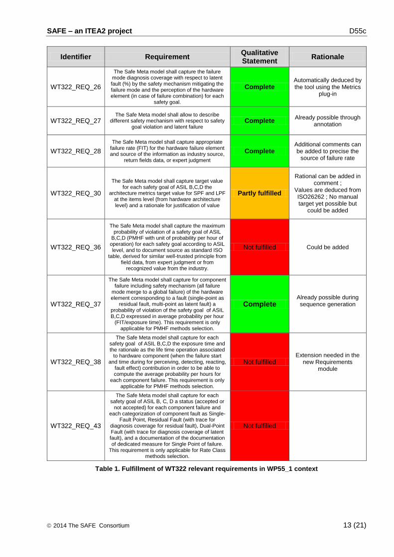
Table 1. Fulfillment of WT322 relevant requirements in WP55_1 context

SAFE – an ITEA2 project D55c
2014 The SAFE Consortium 14 (21)
WT55_REQ_3: The Safety Designer tool shall demonstrate the capability to evaluate qualitatively and quantitatively the safety architecture of the use case.
Identifier Requirement Qualitative Statement
Rationale
WT331_REQ_1
The SAFE Meta-model shall provide a fault modeling language to specify fault information and on which element the fault is attached as well as information about fault propagation.
Complete AltaRica by nature is a
fault modeling language
WT331_REQ_2 The SAFE Meta-model shall allow to
demonstrate that faults at safety concept level do not propagate to safety goal level.
Complete
Through sequence generation and simulation
capabilities in Safety Designer
WT331_REQ_3 The SAFE Meta-model shall support qualitative
and quantitative FTA analysis. Complete
The tool is capable to generate FTA but not from
all models ; Sequences always possible and can
be used as input in a fault tree (sum of products).
WT331_REQ_4 The SAFE Meta-model shall support qualitative
and quantitative FMEA analysis. Partly fulfilled
FMEA possible but not fully corresponding to our
needs especially qualitative FMEA with and without safety mechanism ;
could be deduced from sequence generation
WT331_REQ_9 The SAFE Meta-model shall allow to perform
qualitative safety analyses. Complete
Complete with the new Metrics plug-in
WT331_REQ_10 The SAFE Meta-model shall allow to perform quantitative safety analyses for random HW
failures. Complete
Complete with the new Metrics plug-in
WT331_REQ_11 The SAFE Meta-model shall allow to build
quantitative analysis results based on qualitative analysis results.
Complete As safety analyses
automatically generated complete by nature
WT331_REQ_12
The SAFE Meta-model shall allow to perform and compose deductive safety analyses (FTA or RBD) at different architectural levels and verify
their consistency.
Complete
Analysis results for FTA or sequences that are
automatically generated by the tool are by nature
consistent ; FTA can be recomposed between in
Aralia Fault Tree Analyzer
WT331_REQ_13
The SAFE Meta-model shall allow to perform and compose inductive safety analyses (FMEA
or ETA or Markov) at different architectural levels and verify their consistency
Complete Ok for FMEA
WT331_REQ_14 The SAFE Meta-Model shall display complete results of analyses and allow local display of
component failure impact. Complete
Yes in Debug Information windows + display
WT331_REQ_15 The SAFE Meta-model shall allow to select the most adequate deductive or inductive method.
Complete User can select FMEA or
AltaRica MBSA
WT331_REQ_16 The SAFE Meta-model shall allow to tag
element as safe or SPF faults. Complete
Through analysis results in the new Metrics plug-in
WT331_REQ_17 The SAFE Meta-model shall allow to tag
element as MPF for latent or multiple faults. Complete
Through analysis results in the new Metrics plug-in
WT331_REQ_18
The SAFE Meta-model shall allow the composition and representation of HW
quantified failures and SW unquantified failures (assuming dedicated probability for SW FIT =1).
Complete Not tested in our use case
but possible
WT331_REQ_19 The SAFE Meta-model shall allow the composition of deductive and inductive
methods. Partly fulfilled
Events combinations produced by sequence
generator have their failure rate extracted from manual
FMEA results
SAFE – an ITEA2 project D55c
2014 The SAFE Consortium 15 (21)
Identifier Requirement Qualitative Statement
Rationale
WT331_REQ_20
The SAFE Meta-model shall allow to derive architectural metric targets at different architecture
levels from the Item level and allow to allocate component failure rate.
Not fulfilled Tricky subject
WT331_REQ_21
The SAFE Meta-model shall allow to calculate the architectural metrics at different architecture levels up to the Item level and to compose architectural results and failure rate from different architectural
level.
Partly fulfilled
Not tested but sub model with clear description of interfaces could be re-connected and global
metrics calculated.
WT331_REQ_22
The SAFE Meta-Model shall allow to determine if architectural metrics targets are reached and
allow to identify the root cause when architectural metrics results do not reach target
Complete
Check between realized versus targets is done by the tool automatically with
identification of main contributors
WT331_REQ_24
The SAFE Meta-model shall allow to calculate the Residual Risk using PMHF (Probabilistic Metric for random Hardware Failures) for each safety
goal rated as ASIL C and D based on deductive method extracted from the qualitative method
defined for the SAFE project.
Complete
Sequences are automatically produced in Safety Designer and can be exported transparently
in Aralia Fault Tree in which user can calculate the PMHF (unconditional
failure intensity)
WT331_REQ_27
The SAFE process artifacts shall allow to (semi-)automatically generate parts of the required input model for deductive and inductive safety analyses.
Partly fulfilled
Could be improved ; input & output flows, events, initial state, external clauses are automatically generated
WT331_REQ_28 The SAFE Meta-model shall consider the
exposure duration of in the calculation of the PMHF based on operational situation.
Complete
Possible with law selection in Safety Designer. And also in Aralia Fault Tree
Analyzer.
WT331_REQ_29
The SAFE Meta-model shall allow to determine if PMHF value target is reached and help to identify
root cause by highlighting component contributors.
Partly fulfilled
Main contributor is highlighted through cut sets
analysis. Only missing a comparison between real value versus target but
could be added
WT331_REQ_31
The Safe tool artifact shall allow to implement a means to populate (or capture) the failure rate of
an hardware element and to identify the source as a) industry source, b) return fields data, c) expert
judgment.
Partly fulfilled
Population possible from eFMEA results and source
could be added in comments
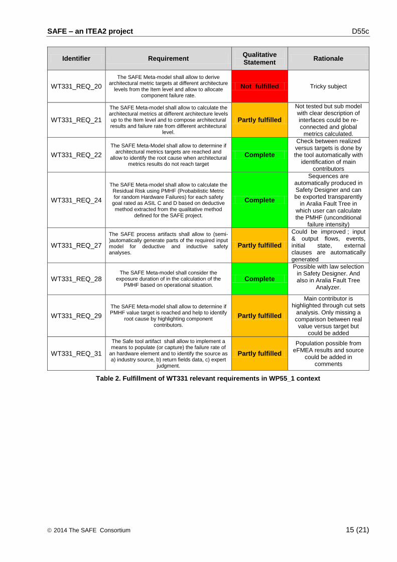
Table 2. Fulfillment of WT331 relevant requirements in WP55_1 context

SAFE – an ITEA2 project D55c
2014 The SAFE Consortium 16 (21)
Performance1 2 3 4 5
4 4 8 12 16 203 3 6 9 12 15
Interest 2 2 4 6 8 101 1 2 3 4 50 0 0 0 0 0
4.1.2 Evaluation of WP 3/4/6 requirements in WP55_1 context
Our evaluation of the Safety Designer / Aralia Fault Tree Analyzer tools from Dassault Systèmes for the Sub-Work Product WP55_1 and more especially the new plug-in for automatic metrics calculations is the following:
Evaluation criteria Qualitative statement Rationale
Correct and comprehensible documentation
Perfect Documentation generally clear. New features are
now implemented with also an example provided to users.
Compliant with SAFE meta-model
Sufficient
Some concepts such as error modeling were available before SAFE new concept. The tool is
able to generate automatically safety analyses and allow simulation with fault injection. It goes beyond
the SAFE meta-model because architectural metrics are automatically generated which is not the
case in WT3.2.2
Correct implementation of SAFE methods
Sufficient Calculation of architectural metrics, EFMEA results
linked to higher abstraction levels
Stability and robustness against incorrect input
Good A checker is available for the AltaRica model that
that highlight incorrect inputs
Correct and seamless interoperability with other SAFE work
products
Incomplete Not interface currently with the SAFE tool platform
Reasonable support for manual or semi-
automated activities Perfect
A part of the AltaRica code is generated automatically from user interface + automatic
generation of safety analyses with metrics calculations.
Training level and expertise required for
usage Good
The new plug-in itself do not need a high level of skill. The main difficulty is the writing of AltaRica code which is not simple for safety engineers not familiar with simulation tools. Normally 5 Days of training are needed to become fully operational.
Tailoring capabilities Sufficient
Sufficient level of tailoring as rules can be set to create the model, simulate the model, generate the safety analyses, annotate the model, and calculate
the metrics.
Table 3. Qualitative evaluation of WP55_1
Final quantification of the Sub-Work Product WP55_1 and more especially the new plug-in for automatic metrics calculations:
Performance: Level: 3 Expectations not fully met or some evaluation criteria not reached sufficient level but significant improvement achieved.
Interest: Level: 4 Interesting for evaluation scenario and ready for application in the field

SAFE – an ITEA2 project D55c
2014 The SAFE Consortium 17 (21)
4.2 Evaluation results for sub-Work Product WP55_2 and more especially the Requirements plug-in
4.2.1 Fulfillment of WP 3/4/6 requirements in WP55_2 context
This section shall summarize the fulfillment of requirements assessed in work task 5.5 that are relevant for the sub-work Product WP55_2.
As the SAFE technology platform was not available at the time when it was decided to build our use case with Safety Designer/Aralia Fault Tree Analyzer tools from Dassault Systèmes and therefore in the following evaluation we would refer to it instead of SAFE.
WT55_REQ_1: The Safety Designer tool shall demonstrate the capability to model and trace safety requirements of the use case.
Identifier Requirement Qualitative Statement
Rationale
WT312_REQ_1
The Safe meta model shall allow defining technical safety requirements and providing traceability
mechanisms between technical safety requirements and functional safety requirements.
Complete Yes through derivation links
WT312_REQ_2 The Safe meta model shall allow tracing the technical
safety requirements against the preliminary architecture of the concept phase.
Complete With Reqtify
WT312_REQ_3 The Safe meta model shall support the definition of
system constraints, e.g. The environmental conditions or functional constraints.
Not fulfilled
WT312_REQ_4
The Safe meta model shall allow tracing technical safety requirements against system constraints,
external interfaces or system configuration requirements.
Not fulfilled
WT312_REQ_5 The Safe meta model shall allow to relate technical safety requirements with the implementing safety
mechanisms Complete Yes through allocation
WT312_REQ_6
The Safe meta model shall allow to label a technical safety requirement in the sense, that this requirement
must be ensured only/also during production, operation, maintenance, repair and decommissioning
Not fulfilled Extension needed in the new
Requirement module
WT312_REQ_8
The Safe meta model shall be able to support a method to validate consistency and compliance
(including traceability coverage) of the preliminary system architecture and technical safety requirement.
Partly fulfilled
Traceability coverage using Reqtify is possible ; Consistency
check is not yet available
WT312_REQ_9 The Safe meta model shall support to allocate technical safety requirements to system design
elements Complete Already possible
WT312_REQ_18 The safe meta model shall support the decomposing the ASIL of requirements according to ISO 26262-9: -
, Clause 5 Not fulfilled
ASIL decomposition not possible today but extension could be added in the new
Requirement module
WT312_REQ_20
Safe meta model shall support the decomposition of initial safety requirements to redundant safety
requirements implemented by sufficiently independent elements.
Partly fulfilled
Need some extensions in the new Requirement module for
ASIL decomposed + independence requirements
Table 4. Fulfillment of WT312 relevant requirements in WP55_2 context

SAFE – an ITEA2 project D55c
2014 The SAFE Consortium 18 (21)
Performance1 2 3 4 5
4 4 8 12 16 203 3 6 9 12 15
Interest 2 2 4 6 8 101 1 2 3 4 50 0 0 0 0 0
4.2.2 Evaluation of WP 3/4/6 requirements in WP55_2 context
Our evaluation of the Safety Designer / Aralia Fault Tree Analyzer tools from Dassault Systèmes for the Sub-Work Product WP55_2 and more especially the new plug-in for requirements is the following:
Evaluation criteria Qualitative statement Rationale
Correct and comprehensible documentation
Not applicable Only a prototype today
Compliant with SAFE meta-model
Incomplete Some constructs of the SAFE meta-model
concerning requirements should be considered
Correct implementation of SAFE methods
Sufficient Goes beyond SAFE methods for expression of requirements in formal ways and verification
Stability and robustness against incorrect input
Incomplete A checker need to be added to ensure consistency
between requirements (ASIL propagation)
Correct and seamless interoperability with other SAFE work
products
Sufficient Through CSV exchange format for requirements ; Maybe REQIF import should be also supported
Reasonable support for manual or semi-
automated activities Sufficient
Sufficient for the moment ; Maybe some help could be added when expressing a requirement in a
formal ways because not so trivial
Training level and expertise required for
usage Not applicable
Only a prototype today but the usage of the requirements plug-in itself is not difficult ; Main difficulty is to get the link between informal and formal expressions and construct the AltaRica
model which is not trivial for safety engineers not familiar with simulation tools
Tailoring capabilities Not applicable Only a prototype but in future tailoring rules could
be set easily
Table 5. Qualitative evaluation of WP55_2
Final quantification of the Sub-Work Product WP55_2 and more especially the new plug-in for requirement management:
Performance: Level: 2 No significant improvement achieved or some evaluation criteria are rated incomplete
Interest: Level: 2 Interesting for evaluation scenario but needs to be significantly matured for application in the field

SAFE – an ITEA2 project D55c
2014 The SAFE Consortium 19 (21)
5 Conclusion
As it was shown during the evaluations the two plug-in developed in safety Designer have not the same maturity:
The new plug-in for requirements managements needs further development and would require some additional research activities because the formal proof of our safety concepts is very interesting but also a very complex subject.
The metrics for architectural metrics is very mature and very powerful. With huge and complex models is it possible to produce in one click the architectural metrics very early in the development phase.
Of course as usual when implementing model based design for the first time a first huge effort is needed. Nevertheless we can expect to reuse model elements for future applications. In general we have notice a better quality of results as well as results available earlier in the development phase than today. In the next table we would try to quantify the benefit in term of effort reduction:
Car Maker Tier 1
Concept Phase
Effort Reduction Not applicable Only 0-10% but
Rationale Not applicable
Better formalism of the functional safety concept.
Simulations capabilities of the functional safety concept.
System Design
Effort Reduction Not applicable Only 0-10 % but
Rationale Not applicable
Better formalism of the technical safety concept.
Early estimation of architectural metrics during the design phase.
Simulations capabilities of the technical safety concept.
Table 6. Quantified benefit of SAFE versus development step
Car Maker Tier 1 Silicon Supplier
HW Development
Effort Reduction Not applicable Not applicable Not applicable
Rationale Not applicable Not applicable Not applicable
SW Development
Effort Reduction Not applicable Not applicable Not applicable
Rationale Not applicable Not applicable Not applicable
Safety Analysis
Effort Reduction Not applicable 20% Not applicable
Rationale Not applicable All 3 metrics can be generated at the same time in one click.
Several safety goals can be addresses at same time.
Better consistency between the different results & Quick updates when a modification is done.
Not applicable
Table 7. Quantified benefit of SAFE versus engineering domain
SAFE – an ITEA2 project D55c
2014 The SAFE Consortium 20 (21)
6 References
[1] SAFE Requirements
https://safe.offis.de/svn/svndav/40_Deliverables/SAFE_D2.1.a/SAFE_D2.1.a.pdf
[2] SAFE Risk List
https://safe.offis.de/svn/svndav/10_Project_Management/SAFE_Plus-Minus-Risks.xlsx
[3] SAFE FPP
https://safe.offis.de/svn/svndav/10_Project_Management/FPP/!Actual_Official_Version/SAFE_FPP.docx
[4] SAFE_D2.1.a-ISO-Part_2.pdf (Management of functional safety)
[5] SAFE_D2.1.a-ISO-Part_3.pdf (Concept Phase)
[6] SAFE_D2.1.a-ISO-Part_4.pdf (Product development at the system level)
[7] SAFE_D2.1.a-ISO-Part_5.pdf (Product development at the hardware level)
[8] SAFE_D2.1.a-ISO-Part_6.pdf (Product development at the software level)
[9] SAFE_D2.1.a-ISO-Part_7.pdf (Production and operation)
[10] SAFE_D2.1.a-ISO-Part_8.pdf (Supporting Processes)
[11] SAFE_D2.1.a-ISO-Part_9.pdf (Automotive Safety Integrity Level (ASIL)-oriented safety-oriented analysis

SAFE – an ITEA2 project D55c
2014 The SAFE Consortium 21 (21)
7 Acknowledgments
This document is based on the SAFE project in the framework of the ITEA2, EUREKA cluster program Σ! 3674. The work has been funded by the German Ministry for Education and Research (BMBF) under the funding ID 01IS11019, and by the French Ministry of the Economy and Finance (DGCIS). The responsibility for the content rests with the authors.