SAE architecture Interworking with 2G/3G Networks MME UPE SAE GW Operator IP services (including...
29
SAE architecture Interworking with 2G/3G Networks MME UPE SAE GW Operator IP services (including IMS, PSS, ...) Evolved Packet Core S11 S2 S3 S4 S7 S6 SG i S1 Gb Iu Rx+ LTE Uu X2 E-UTRAN PDN SAE GW S5 eNB cel l eNB cel l GERAN UTRAN HSS GPRS Core PCRF Um Uu LTE Uu
-
Upload
edward-lamb -
Category
Documents
-
view
222 -
download
2
Transcript of SAE architecture Interworking with 2G/3G Networks MME UPE SAE GW Operator IP services (including...
SAE architecture Interworking with 2G/3G Networks
MME UPE SAEGW
Operator IP services
(including IMS, PSS, ...)
Evolved Packet Core
S11
S2
S3 S4
S7
S6
SGiS1
Gb
IuRx+
LTE Uu
X2
E-UTRAN
PDNSAE GW
S5eNB
cell
eNB
cell
GERAN
UTRAN
HSS
GPRSCore
PCRF
Um
Uu
LTE Uu
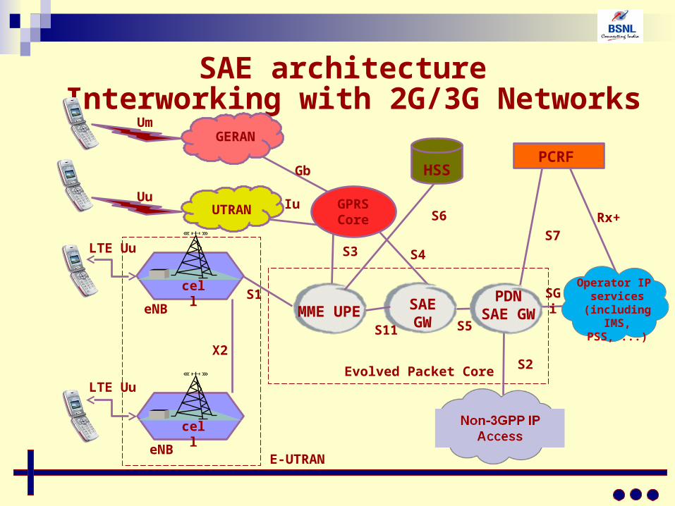
LTE uses OFDM for the Downlink Link.
LTE uses SC-FDMA for the Uplink.
LTE Air Interface
UE
eNB
cell
OFDMA D/L Tx
SC- FDMA U/L Tx
OFDM Basic Concepts
OFDM is a multicarrier system.
Orthogonal Frequency Division Multiplex (OFDM) is a form of transmission that uses a large number of close spaced carriers that are modulated with low rate data.
Normally these signals would be expected to interfere with each other, but by making the signals orthogonal to each another there is no mutual interference.
Ch.1
Ch.2 Ch.3 Ch.4 Ch.5 Ch.6 Ch.7 Ch.8 Ch.9 Ch.10
Ch.3 Ch.5 Ch.7 Ch.9Ch.2 Ch.4 Ch.6 Ch.8 Ch.10
Ch.1
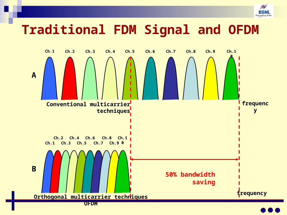
Conventional multicarrier techniques
Orthogonal multicarrier techniques OFDM
50% bandwidth saving
frequency
frequency
A
B
Traditional FDM Signal and OFDM
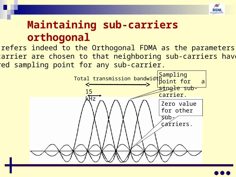
The OFDMA refers indeed to the Orthogonal FDMA as the parameters for the sub-carrier are chosen to that neighboring sub-carriers have zero value the desired sampling point for any sub-carrier.
Total transmission bandwidth
Maintaining sub-carriers orthogonal
Zero value for other sub-carriers.
Sampling point for a single sub-carrier.
15 kHz
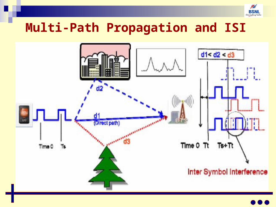
Multi‐Path Propagation and ISI
The cancellation of inter‐symbol interference(ISI) makes hardware design of the receivers more complex.
In WCDMA for instance the RAKE receiver requires a huge amount of DSP capacity.
One of the goals of future radio systems is to simplify receiver design.
Multi‐Path Propagation and ISI
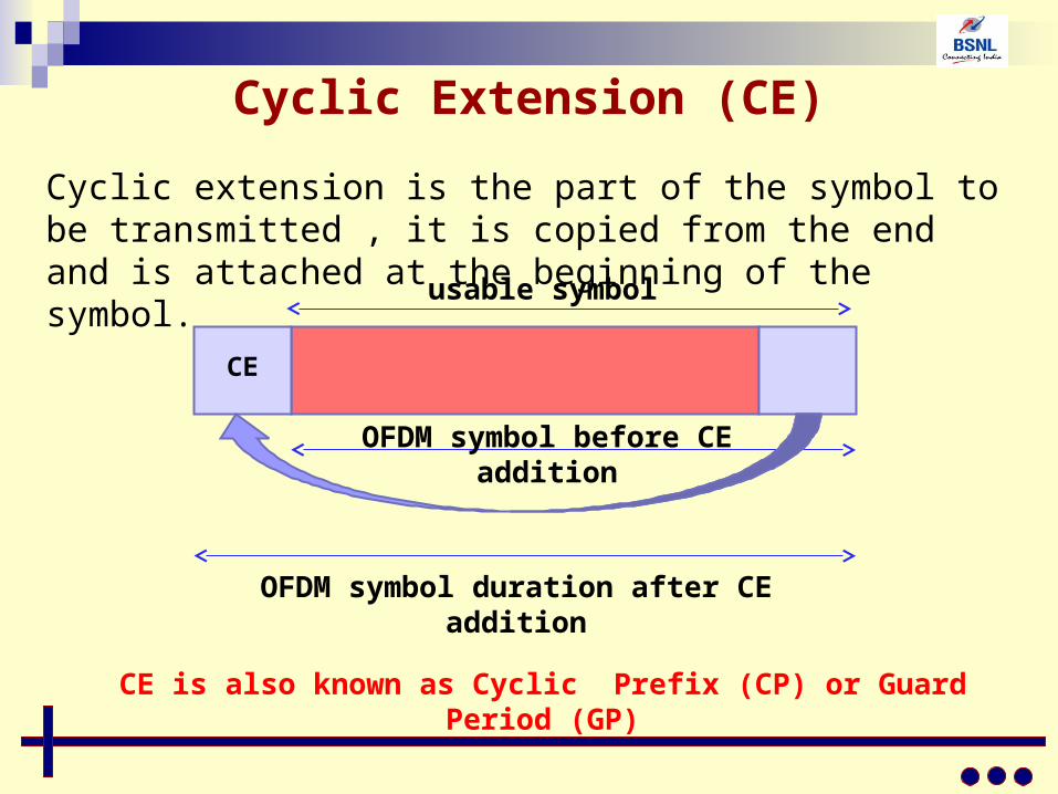
Cyclic Extension (CE)
Cyclic extension is the part of the symbol to be transmitted , it is copied from the end and is attached at the beginning of the symbol.
OFDM symbol before CE addition
CE
OFDM symbol duration after CE addition
CE is also known as Cyclic Prefix (CP) or Guard Period (GP)
usable symbol
InterferenceUser SubCarriers
Allocation
SubCarriers
Interference
SubCarriers
NulledSubCarriers
Total Frequency band
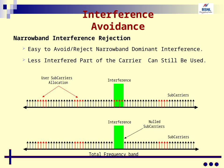
Narrowband Interference Rejection
Easy to Avoid/Reject Narrowband Dominant Interference.
Less Interfered Part of the Carrier Can Still Be Used.
Interference Avoidance
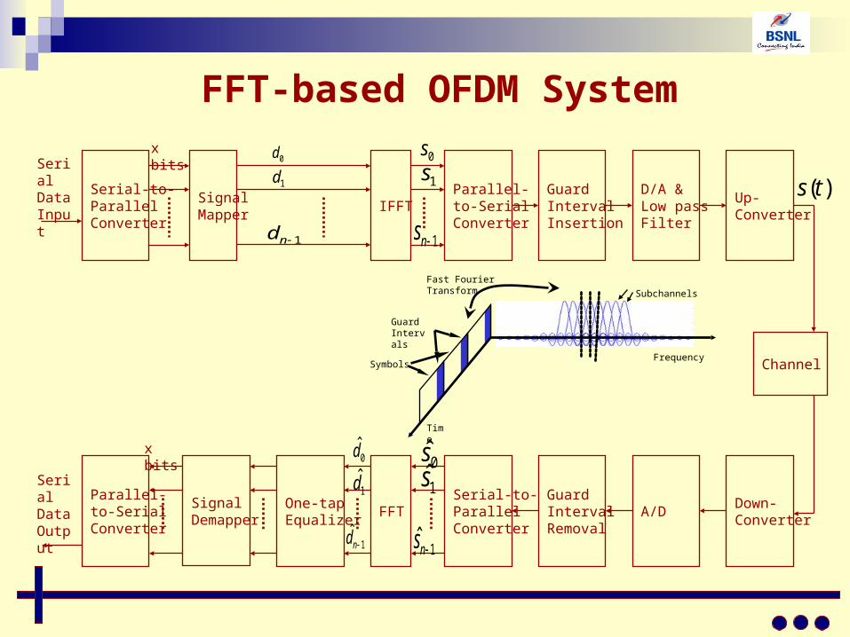
FFT-based OFDM System
Serial-to-ParallelConverter
SignalMapper
IFFTParallel-to-SerialConverter
GuardIntervalInsertion
Serial Data Input
x bits0d
1d
1nd
0s
1s
1ns
D/A &Low passFilter
Up-Converter
Down-Converter
A/D GuardIntervalRemoval
Serial-to-ParallelConverter
FFTOne-tapEqualizer
SignalDemapper
Parallel-to-SerialConverter
Serial Data Output
0dx bits
1d
1ˆ
nd
0s1s
1ˆ ns
Channel
)(ts
Time
Frequency
Subchannels
Fast Fourier Transform
Guard Intervals
Symbols
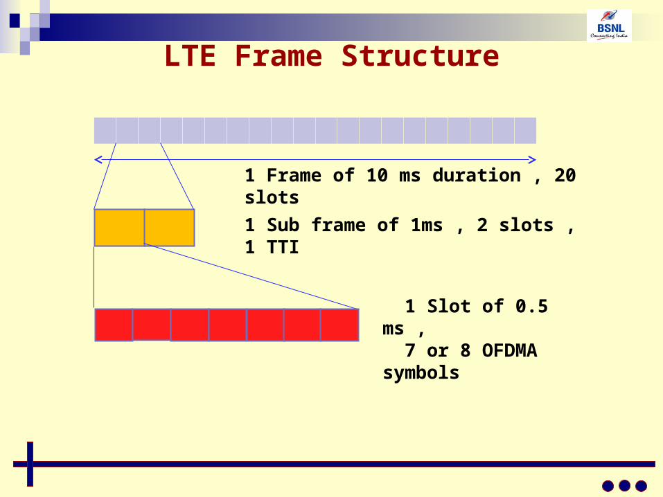
LTE Frame Structure
1 Frame of 10 ms duration , 20 slots
1 Sub frame of 1ms , 2 slots , 1 TTI
1 Slot of 0.5 ms , 7 or 8 OFDMA symbols
What is Resource Element (RE)?
A Resource Element (RE) is one OFDM symbol (in the time
domain) of 1 subcarriers (in the frequency domain). It is the
minimum unit of data allocation and power control.
However resource allocation is always done as a group of
REs called Resource Block.
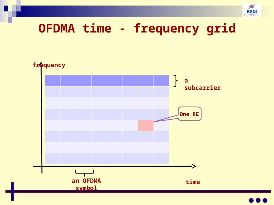
OFDMA time - frequency grid
a subcarrier
an OFDMA symbol
time
frequency
One RE
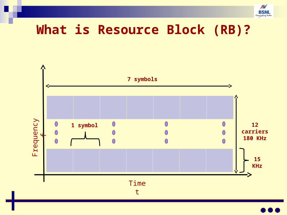
What is Resource Block (RB)?
A Resource Block (RB) is defined as set of 7 consecutive
OFDM symbols in the time domain and set of 12 consecutive
subcarriers in the frequency domain.
The resource block in the specifications refers to 0.5 ms slot,
but the resource allocation is done anyway with the 1 ms
resolution in the time domain (per sub-frame or 1 TTI).
It is the task of the scheduler to assign resource blocks to
physical channels belonging to different users .
What is Resource Block (RB)?
Time t
Fre
quen
cy
f
1 symbol
15 KHz
7 symbols
12 carriers180 KHz
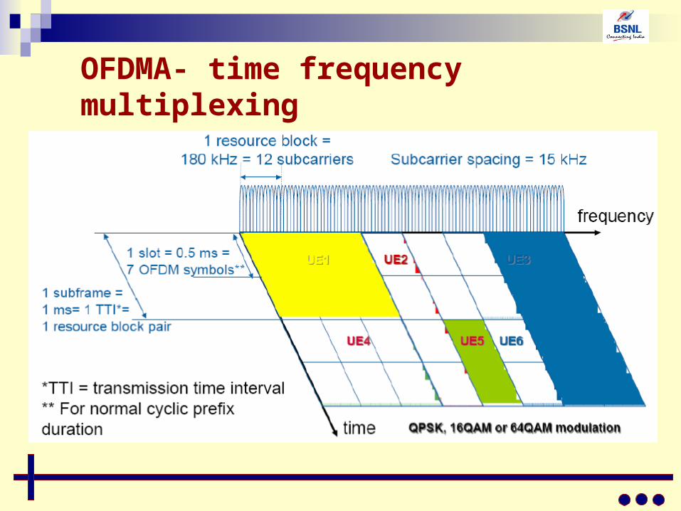
OFDMA- time frequency multiplexing
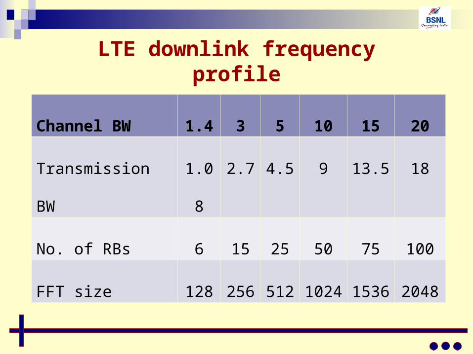
LTE downlink frequency profile
Channel BW 1.4 3 5 10 15 20
Transmission BW 1.08 2.7 4.5 9 13.5 18
No. of RBs 6 15 25 50 75 100
FFT size 128 256 512 1024 1536 2048
Single-carrier FDMA
LTE uses OFDMA for downlink but not for uplink.
Instead of OFDMA ,LTE uses SC-FDMA in uplink.
Why ?
Why SC FDMA in Uplink ?
The OFDM transmission consists of several parallel sub- carriers in frequency domain. In the time domain this corresponds to multiple sinusoidal waves with different frequency components and occupying the system bandwidth with steps of 15KHz.
The combined signal envelope vary strongly.
This causes challenges to the amplifier design.
……
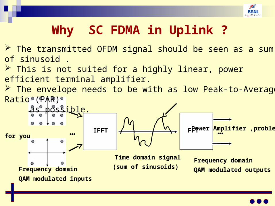
The transmitted OFDM signal should be seen as a sum of sinusoid . This is not suited for a highly linear, power efficient terminal amplifier. The envelope needs to be with as low Peak-to-Average Ratio (PAR) as possible.
Power Amplifier ,problem for you
IFFT
Frequency domain
QAM modulated inputs
Time domain signal
(sum of sinusoids)
FFT
Frequency domain
QAM modulated outputs
Why SC FDMA in Uplink ?
Why SC FDMA in Uplink ?
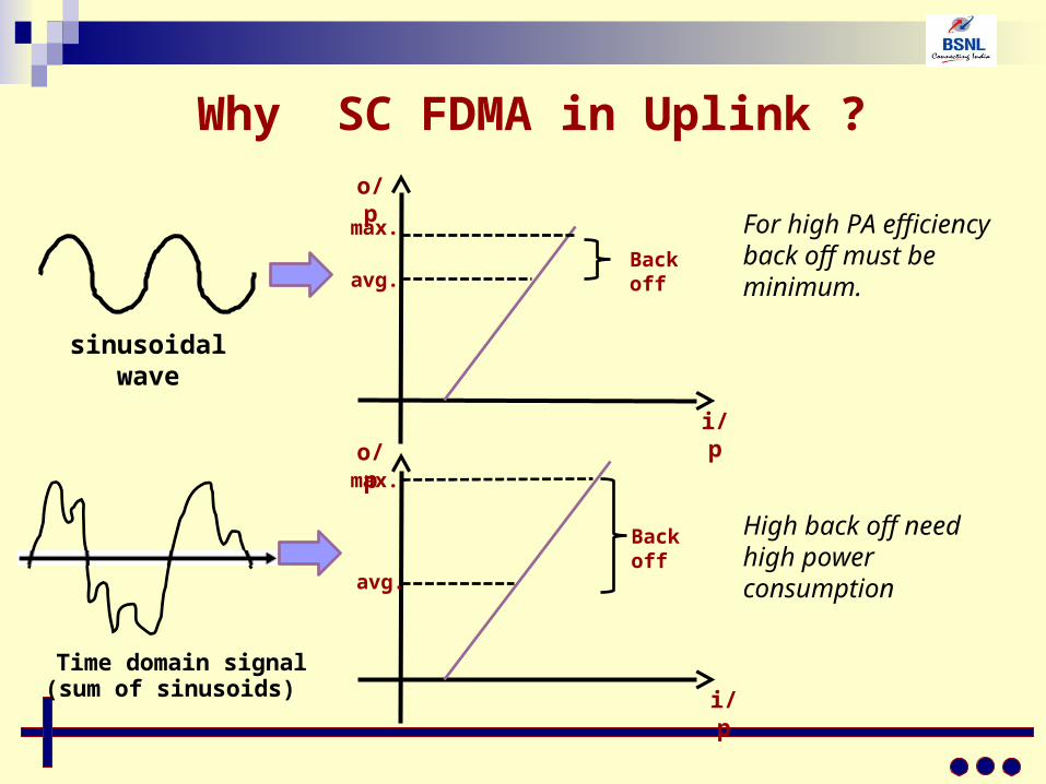
Time domain signal (sum of sinusoids)
sinusoidal wave
max.
avg.
max.
avg.
Back off
Back off
i/p
i/p
o/p
o/p
For high PA efficiency back off must be minimum.
High back off need high power consumption
Why SC FDMA in Uplink ?
Power consumption in user equipment (UE) terminals is limited by battery.
OFDM requires large dynamic range due to high peak to average power ratio(PAPR).
Liner power amplifiers with wide dynamic range have bad efficiency.
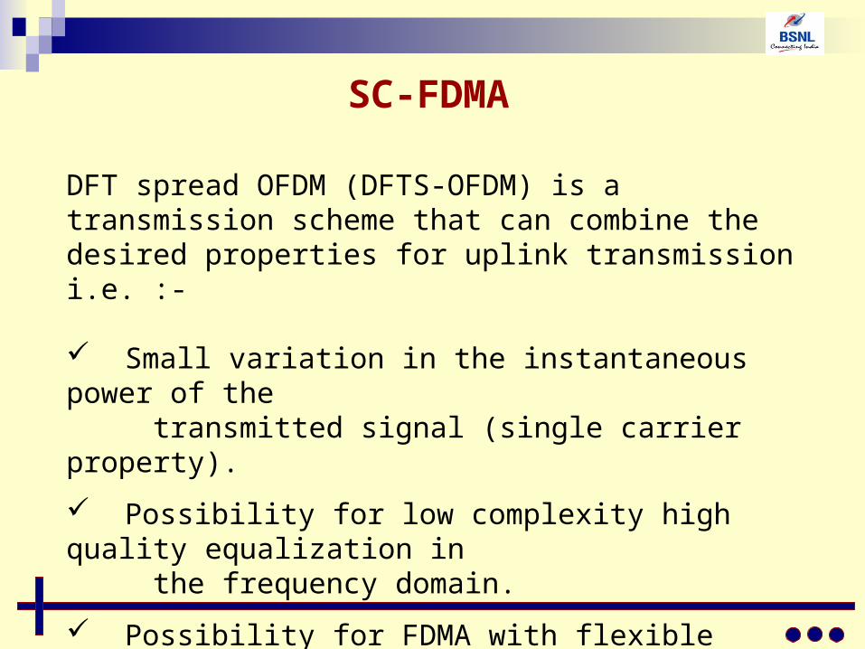
SC-FDMA
DFT spread OFDM (DFTS-OFDM) is a transmission scheme that can combine the desired properties for uplink transmission i.e. :-
Small variation in the instantaneous power of the transmitted signal (single carrier property).
Possibility for low complexity high quality equalization in the frequency domain.
Possibility for FDMA with flexible bandwidth assignment.
SC-FDMA can be referred as DFTS- OFDMA
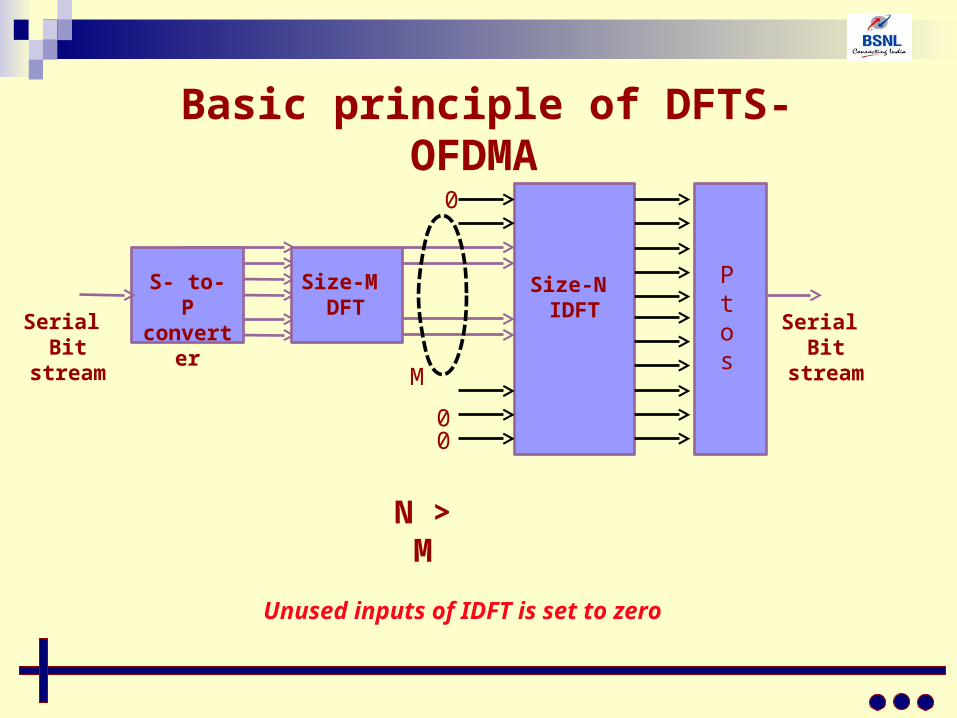
Basic principle of DFTS-OFDMA
S- to- P converter
Size-M DFT
Size-N IDFT
M
00
0
Serial Bit
stream
Ptos Serial
Bit stream
N > M
Unused inputs of IDFT is set to zero
S C constellation
mappi ng
S-to-P converter
Sub carrier
mapping
N- point IDFT
M- point DFT
P-to-S converter
CP insertion
RF
S C detector and
constellation demappi ng
P-to-S converter
Frequency domain
equalizer
N- point DFT
M- point IDFT
S-to-P converter
CP removal
RF
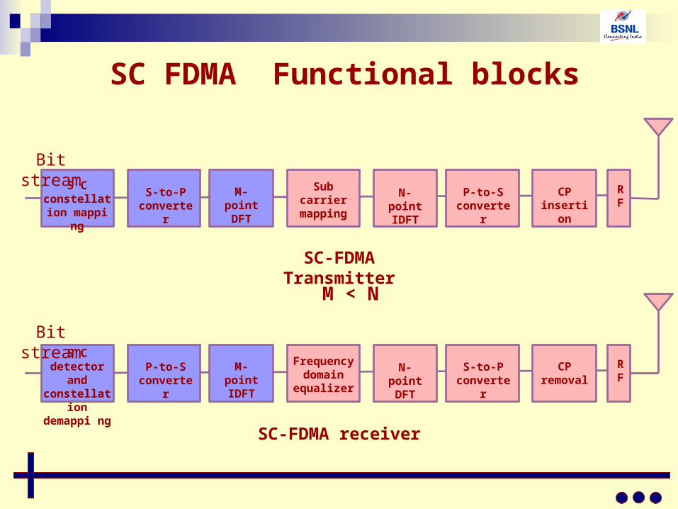
SC FDMA Functional blocks
SC-FDMA Transmitter
SC-FDMA receiver
Bit stream
Bit stream
M < N
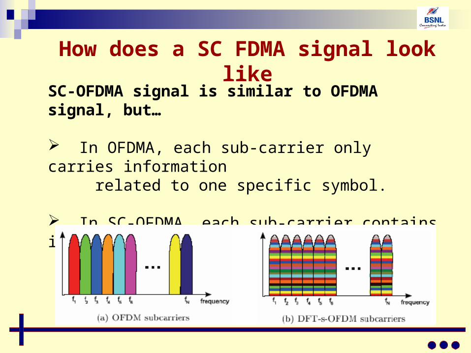
How does a SC FDMA signal look like
SC-OFDMA signal is similar to OFDMA signal, but…
In OFDMA, each sub-carrier only carries information related to one specific symbol.
In SC-OFDMA, each sub-carrier contains information of all transmitted symbols.
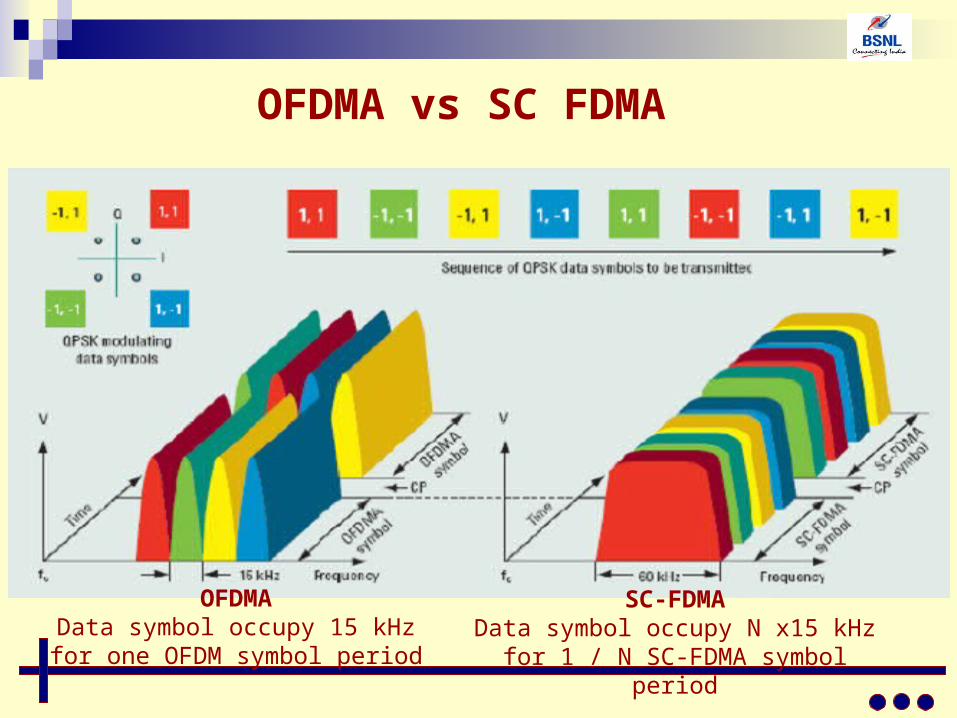
OFDMA vs SC FDMA
OFDMAData symbol occupy 15 kHz for one
OFDM symbol period
SC-FDMAData symbol occupy N x15 kHz for 1 / N
SC-FDMA symbol period
frequency
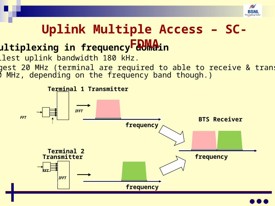
User multiplexing in frequency domain• Smallest uplink bandwidth 180 kHz.• Largest 20 MHz (terminal are required to able to receive & transmit up to
20 MHz, depending on the frequency band though.)
Terminal 1 Transmitter
IFFT
FFT
Terminal 2 Transmitter
FFT
IFFT
frequency BTS Receiver
frequency
Uplink Multiple Access – SC-FDMA