SA FE TY SW IT CHSa fe ty Swit ch All dimensions in mm. The size is greatly reduced while achieving...
28
Protecting workers on-site SAFETY SWITCH Interlock Switches with Solenoid HS5L 2-Contact/4-Contact
Transcript of SA FE TY SW IT CHSa fe ty Swit ch All dimensions in mm. The size is greatly reduced while achieving...

Protecting workers on-site
S A F E T Y S W I T C H
Interlock Switches with SolenoidHS5L 2-Contact/4-Contact
2-Contact
Interlock Switch
Packing
Baking Pressing
Squeezing
Cutting Grinding
Mixing Rotating
with high cost performance are ideal for customerswho want to make use of the above advantages.
with high cost performance are ideal for customerswho want to make use of the above advantages.
with high cost performance are ideal for customerswho want to make use of the above advantages.
with high cost performance are ideal for customerswho want to make use of the above advantages.
Applications
Advantages
Sa
fe
ty
S
wi
tc
h
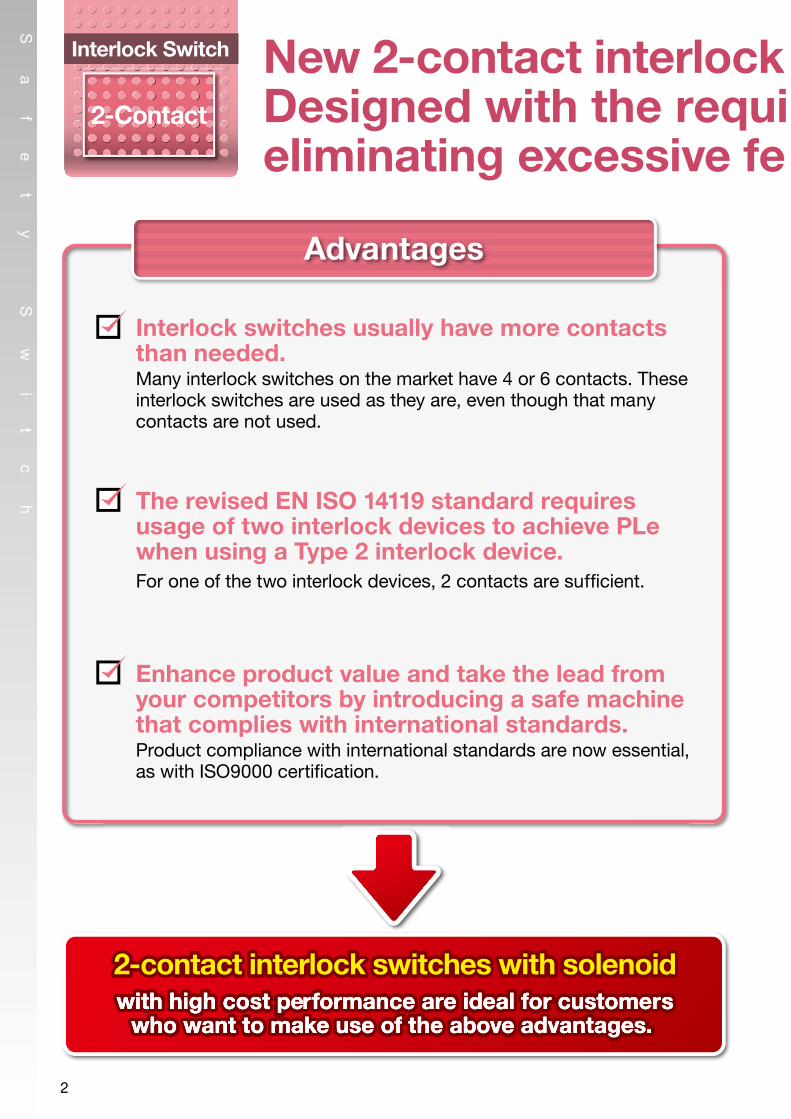
Interlock switches usually have more contacts than needed.Many interlock switches on the market have 4 or 6 contacts. These interlock switches are used as they are, even though that many contacts are not used.
The revised EN ISO 14119 standard requires usage of two interlock devices to achieve PLe when using a Type 2 interlock device.For one of the two interlock devices, 2 contacts are suf�cient.
Enhance product value and take the lead from your competitors by introducing a safe machine that complies with international standards.Product compliance with international standards are now essential, as with ISO9000 certi�cation.
2-contact interlock switches with solenoid
Ideal as a safety measure for use on machines that do not shut down immediately or maintain high temperatures.
New 2-contact interlock switches with solenoid.Designed with the requi red safety level, while eliminating excessive fe atures.
2

2-Contact
Interlock Switch
Packing
Baking Pressing
Squeezing
Cutting Grinding
Mixing Rotating
with high cost performance are ideal for customerswho want to make use of the above advantages.
with high cost performance are ideal for customerswho want to make use of the above advantages.
with high cost performance are ideal for customerswho want to make use of the above advantages.
with high cost performance are ideal for customerswho want to make use of the above advantages.
Applications
Advantages
Sa
fe
ty
S
wi
tc
h
Interlock switches usually have more contacts than needed.Many interlock switches on the market have 4 or 6 contacts. These interlock switches are used as they are, even though that many contacts are not used.
The revised EN ISO 14119 standard requires usage of two interlock devices to achieve PLe when using a Type 2 interlock device.For one of the two interlock devices, 2 contacts are suf�cient.
Enhance product value and take the lead from your competitors by introducing a safe machine that complies with international standards.Product compliance with international standards are now essential, as with ISO9000 certi�cation.
2-contact interlock switches with solenoid
Ideal as a safety measure for use on machines that do not shut down immediately or maintain high temperatures.
New 2-contact interlock switches with solenoid.Designed with the requi red safety level, while eliminating excessive fe atures.
3
Sa
fe
ty
S
wi
tc
h
All dimensions in mm.
The size is greatly reduced while achieving the same 1400N (Fzh) locking strength as the conventional HS5E series. (GS-ET-19)
Compact with powerful 1400N locking strength
Head removal detection circuitry is employed in the HS5L. With this innovative function, the monitor circuit (41-42) turns off when the head is removed from the switch, such as when removing the head to change the head direction (applicable with the HS5L spring lock models). For example, for circuit codes: VB, VD and DD, which have two or more lock monitor circuits installed, removing the head results in disparity (41-42: OFF, 51-52: ON). This disparity is detected by the head removal detection function.
ection circuitry is employed in the HS5L Wit
Head Removal Detection Circuitry
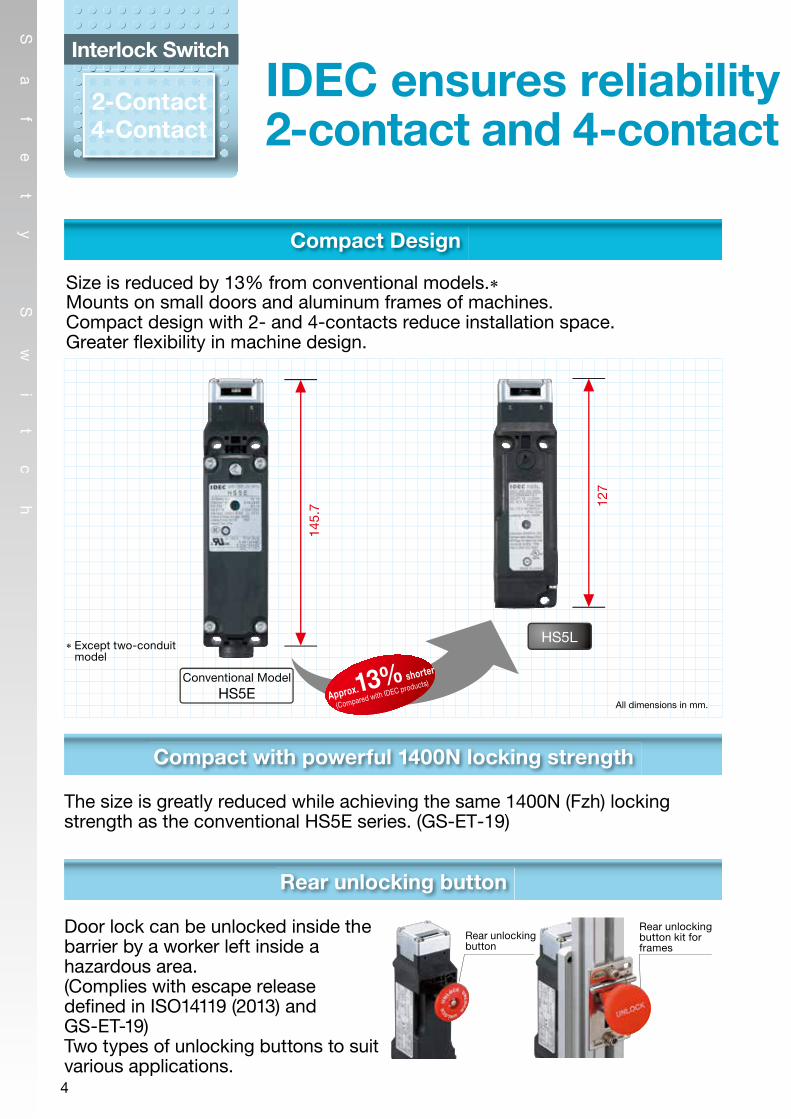
Door lock can be unlocked inside thebarrier by a worker left inside ahazardous area.(Complies with escape release de�ned in ISO14119 (2013) and GS-ET-19) Two types of unlocking buttons to suit various applications.
Rear unlocking button
Approx.13% shorter
(Compared with IDEC products)
127
145.
7
HS5L
Conventional ModelHS5E
Spring clamp terminals
Spring clamp terminals offer excellent vibration resistance, preventing wires from loosening. No need for additional tightening.
Energy saving!
Solenoid energy consumption: 200mAReduced by 25% from conventional HS5E series.
Actuatorunlocked
OFF ON
OFF ON
OFF
ON
Note: Head removal detection function is not a direct opening action mechanism.
Actuator unlocked Actuator locked Head removed
● HS5L-VD44M-G (Lock monitor circuit)
5251
41Lock monitor circuit
Lock monitor circuit
42
A1A2(+) (–)
Rear unlockingbutton
Rear unlocking button kit forframes
Wiring port
Wiring port
Driver port
Driver port
Head removal detection function
Monitor circuit (41-42)
Disparity
Size is reduced by 13% from conventional models.∗Mounts on small doors and aluminum frames of machines. Compact design with 2- and 4-contacts reduce installation space. Greater �exibility in machine design.
2-Contact4-Contact
Interlock Switch
IDEC ensures reliability and performance. 2-contact and 4-contact interlock switches with solenoid.
Compact Design Two-conduit Model
Cable can be connected to the right, left, or bottom (for straight cable orientation) of the terminal cover. Possible to use long marking tubes with the wiring cables.
∗ Except two-conduitmodel
Left cable orientation
Straight cable orientation
Right cable orientation
266mA
200mA
Approx. 25% reduced
(Compared with IDEC products)
HS5LConventional Model HS5E
4

Sa
fe
ty
S
wi
tc
h
All dimensions in mm.
The size is greatly reduced while achieving the same 1400N (Fzh) locking strength as the conventional HS5E series. (GS-ET-19)
Compact with powerful 1400N locking strength
Head removal detection circuitry is employed in the HS5L. With this innovative function, the monitor circuit (41-42) turns off when the head is removed from the switch, such as when removing the head to change the head direction (applicable with the HS5L spring lock models). For example, for circuit codes: VB, VD and DD, which have two or more lock monitor circuits installed, removing the head results in disparity (41-42: OFF, 51-52: ON). This disparity is detected by the head removal detection function.
ection circuitry is employed in the HS5L Wit
Head Removal Detection Circuitry
Door lock can be unlocked inside thebarrier by a worker left inside ahazardous area.(Complies with escape release de�ned in ISO14119 (2013) and GS-ET-19) Two types of unlocking buttons to suit various applications.
Rear unlocking button
Approx.13% shorter
(Compared with IDEC products)
127
145.
7
HS5L
Conventional ModelHS5E
Spring clamp terminals
Spring clamp terminals offer excellent vibration resistance, preventing wires from loosening. No need for additional tightening.
Energy saving!
Solenoid energy consumption: 200mAReduced by 25% from conventional HS5E series.
Actuatorunlocked
OFF ON
OFF ON
OFF
ON
Note: Head removal detection function is not a direct opening action mechanism.
Actuator unlocked Actuator locked Head removed
● HS5L-VD44M-G (Lock monitor circuit)
5251
41Lock monitor circuit
Lock monitor circuit
42
A1A2(+) (–)
Rear unlockingbutton
Rear unlocking button kit forframes
Wiring port
Wiring port
Driver port
Driver port
Head removal detection function
Monitor circuit (41-42)
Disparity
Size is reduced by 13% from conventional models.∗Mounts on small doors and aluminum frames of machines. Compact design with 2- and 4-contacts reduce installation space. Greater �exibility in machine design.
2-Contact4-Contact
Interlock Switch
IDEC ensures reliability and performance. 2-contact and 4-contact interlock switches with solenoid.
Compact Design Two-conduit Model
Cable can be connected to the right, left, or bottom (for straight cable orientation) of the terminal cover. Possible to use long marking tubes with the wiring cables.
∗ Except two-conduitmodel
Left cable orientation
Straight cable orientation
Right cable orientation
266mA
200mA
Approx. 25% reduced
(Compared with IDEC products)
HS5LConventional Model HS5E
5

Actuators can be selected according to door shapes and usage, and can be installed �exibly according to the installation site.
Sliding Actuator
Plug Actuator
Padlock HaspStraight Actuator
Right-angle Actuator
Spring loaded actuator
IDEC patented spring loaded actuator locks the door safely when the door bounces. When the actuator is fully inserted (door closed completely), the door can tolerate a space of up to 16mm. Patent acquired
HS5L interlock switch and HS9Z-BA5 spring loaded actuator
HS5L interlock switch and HS9Z-A51A straight actuator
∗ Accessory exclusive for HS5L.
Actuators can be selected according to door shapes and usage. •Actuator with rubber bushing ideal for use
on rattling doors.
•Plug actuators ideal for use on heavily rattling doors.
•Movable actuators ideal for use on hinged doors.
•Sliding actuators for easy installation.
•Actuators ideal for use on bouncing doorsalso available.
Lock
16
(1) Insert
Does not lock
(1) Insert
16
4.6
Conventional model
Wide variety of actuators
Sa
fe
ty
S
wi
tc
h
Right-angle Actuator with rubber bushing
Straight Actuator with rubber bushing
Spring Loaded Actuator
∗ Accessory exclusive for HS5L.
Angle Adjustable (vertical) Actuator
HS5 series
Actuator Wide variety of actuators for interlock switches enhance �exibility and usability!
(2) Fully inserted (door completely shut) (3) Door bounces
The door can bounce open to up to 16mm.
Locking positionof HS9Z-A51A
(2) Fully inserted (door completely shut) (3) Door bounces
The door can bounce open to up to 4.6mm.
Locking positionof HS9Z-A51A
6
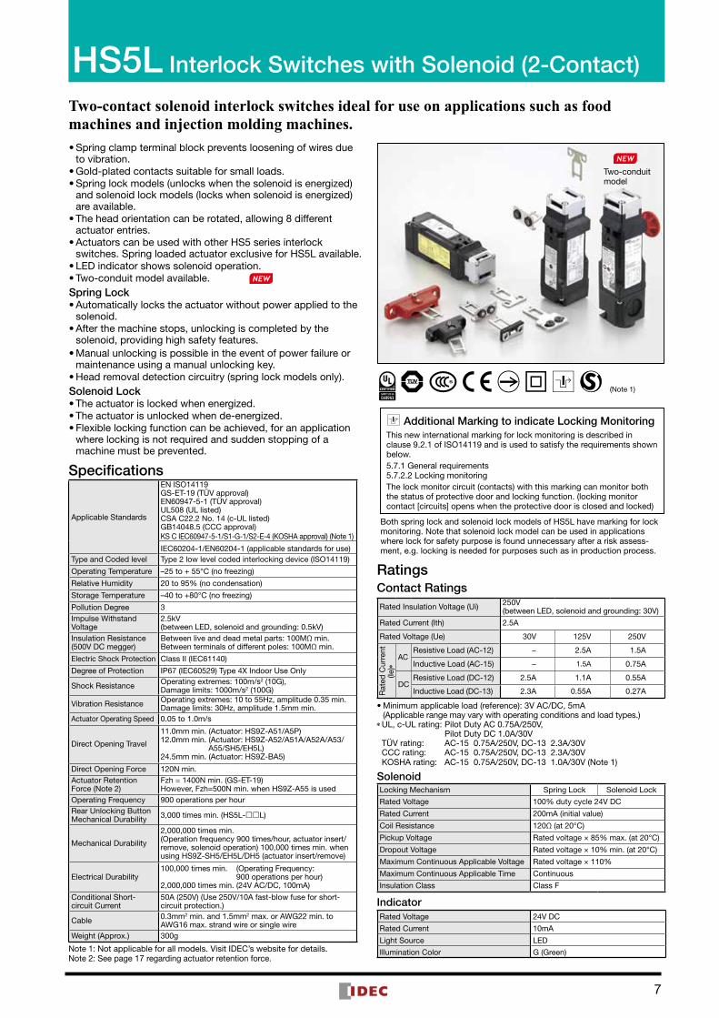
Two-contact solenoid interlock switches ideal for use on applications such as food machines and injection molding machines. •Spring clamp terminal block prevents loosening of wires due to vibration. •Gold-plated contacts suitable for small loads. •Spring lock models (unlocks when the solenoid is energized) and solenoid lock models (locks when solenoid is energized) are available. •The head orientation can be rotated, allowing 8 different actuator entries. •Actuators can be used with other HS5 series interlock switches. Spring loaded actuator exclusive for HS5L available. • LED indicator shows solenoid operation. •Two-conduit model available.
Spring Lock •Automatically locks the actuator without power applied to the solenoid. •After the machine stops, unlocking is completed by the solenoid, providing high safety features. •Manual unlocking is possible in the event of power failure or maintenance using a manual unlocking key. •Head removal detection circuitry (spring lock models only).
Solenoid Lock •The actuator is locked when energized. •The actuator is unlocked when de-energized. •Flexible locking function can be achieved, for an application where locking is not required and sudden stopping of a machine must be prevented.
Specifications
Applicable Standards
EN ISO14119GS-ET-19 (TÜV approval)EN60947-5-1 (TÜV approval)UL508 (UL listed)CSA C22.2 No. 14 (c-UL listed)GB14048.5 (CCC approval)KS C IEC60947-5-1/S1-G-1/S2-E-4 (KOSHA approval) (Note 1)
IEC60204-1/EN60204-1 (applicable standards for use)Type and Coded level Type 2 low level coded interlocking device (ISO14119)
Operating Temperature –25 to + 55°C (no freezing)
Relative Humidity 20 to 95% (no condensation)
Storage Temperature –40 to +80°C (no freezing)
Pollution Degree 3Impulse Withstand Voltage
2.5kV (between LED, solenoid and grounding: 0.5kV)
Insulation Resistance (500V DC megger)
Between live and dead metal parts: 100MΩ min.Between terminals of different poles: 100MΩ min.
Electric Shock Protection Class II (IEC61140)
Degree of Protection IP67 (IEC60529) Type 4X Indoor Use Only
Shock Resistance Operating extremes: 100m/s2 (10G), Damage limits: 1000m/s2 (100G)
Vibration Resistance Operating extremes: 10 to 55Hz, amplitude 0.35 min.Damage limits: 30Hz, amplitude 1.5mm min.
Actuator Operating Speed 0.05 to 1.0m/s
Direct Opening Travel
11.0mm min. (Actuator: HS9Z-A51/A5P)12.0mm min. (Actuator: HS9Z-A52/A51A/A52A/A53/ A55/SH5/EH5L)24.5mm min. (Actuator: HS9Z-BA5)
Direct Opening Force 120N min.Actuator Retention Force (Note 2)
Fzh = 1400N min. (GS-ET-19)However, Fzh=500N min. when HS9Z-A55 is used
Operating Frequency 900 operations per hourRear Unlocking Button Mechanical Durability 3,000 times min. (HS5L-L)
Mechanical Durability
2,000,000 times min.(Operation frequency 900 times/hour, actuator insert/remove, solenoid operation) 100,000 times min. when using HS9Z-SH5/EH5L/DH5 (actuator insert/remove)
Electrical Durability100,000 times min. (Operating Frequency: 900 operations per hour)2,000,000 times min. (24V AC/DC, 100mA)
Conditional Short-circuit Current
50A (250V) (Use 250V/10A fast-blow fuse for short- circuit protection.)
Cable 0.3mm2 min. and 1.5mm2 max. or AWG22 min. to AWG16 max. strand wire or single wire
Weight (Approx.) 300g
Note 1: Not applicable for all models. Visit IDEC’s website for details.Note 2: See page 17 regarding actuator retention force.
RatingsContact RatingsRated Insulation Voltage (Ui) 250V
(between LED, solenoid and grounding: 30V)
Rated Current (Ith) 2.5A
Rated Voltage (Ue) 30V 125V 250V
Rat
ed C
urre
nt
(Ie)∗
ACResistive Load (AC-12) − 2.5A 1.5A
Inductive Load (AC-15) − 1.5A 0.75A
DCResistive Load (DC-12) 2.5A 1.1A 0.55A
Inductive Load (DC-13) 2.3A 0.55A 0.27A
•Minimum applicable load (reference): 3V AC/DC, 5mA (Applicable range may vary with operating conditions and load types.)
∗UL, c-UL rating: Pilot Duty AC 0.75A/250V, Pilot Duty DC 1.0A/30V TÜV rating: AC-15 0.75A/250V, DC-13 2.3A/30V CCC rating: AC-15 0.75A/250V, DC-13 2.3A/30V KOSHA rating: AC-15 0.75A/250V, DC-13 1.0A/30V (Note 1)
SolenoidLocking Mechanism Spring Lock Solenoid Lock
Rated Voltage 100% duty cycle 24V DC
Rated Current 200mA (initial value)
Coil Resistance 120Ω (at 20°C)
Pickup Voltage Rated voltage × 85% max. (at 20°C)
Dropout Voltage Rated voltage × 10% min. (at 20°C)
Maximum Continuous Applicable Voltage Rated voltage × 110%
Maximum Continuous Applicable Time Continuous
Insulation Class Class F
IndicatorRated Voltage 24V DC
Rated Current 10mA
Light Source LED
Illumination Color G (Green)
Additional Marking to indicate Locking MonitoringThis new international marking for lock monitoring is described in clause 9.2.1 of ISO14119 and is used to satisfy the requirements shown below.5.7.1 General requirements5.7.2.2 Locking monitoringThe lock monitor circuit (contacts) with this marking can monitor both the status of protective door and locking function. (locking monitor contact [circuits] opens when the protective door is closed and locked)
HS5L Interlock Switches with Solenoid (2-Contact)
(Note 1)
Both spring lock and solenoid lock models of HS5L have marking for lock monitoring. Note that solenoid lock model can be used in applications where lock for safety purpose is found unnecessary after a risk assess-ment, e.g. locking is needed for purposes such as in production process.
Two-conduit model
7

8
HS5L Interlock Switches with Solenoid (2-Contact)2-Contact Package Quantity: 1
Circuit Code Contact Configuration Gland Port Size
Spring lock Solenoid
Part No.
XD
Monitor Circuit:
24231211
1211Monitor Circuit:
Monitor Circuit:Monitor Circuit:
4241
A2 A1
42415251
Monitor Circuit:Monitor Circuit:
21 221211Monitor Circuit:
Monitor Circuit:
Door Monitor(Actuator inserted)
Lock MonitorSpring lock→Solenoid OFFSolenoid lock→Solenoid ON
(Note)
(Note)(Note)
M20
HS5L-XD44M-G HS5L-XD7Y4M-G
XF — HS5L-XF7Y4M-G
XG — HS5L-XG7Y4M-G
XH
HS5L-XH44M-G
HS5L-XH7Y4M-G
XH HS5L-XH44LM-G(Rear Unlocking Button Model)
•The contact configuration shows the status when the actuator is inserted and the switch is locked.•Actuators are not supplied with the interlock switch and must be ordered separately.•Contact us for details of two-conduit model. (Part No: HS5L- SM-G)
Circuit Diagrams and Operating CharacteristicsSpring Lock
Interlock Switch Status
Status 1 Status 2 Status 3 Status 4Door ClosedMachine ready to operateSolenoid de-energized
Door ClosedMachine cannot be operatedSolenoid energized
Door openMachine cannot be operatedSolenoid energized
Door openMachine cannot be operatedSolenoid de-energized
Door Status
Circuit Example: HS5L-XD411 12 4241
(+) (–)A2 A1 A2 A1
11 12 4241
(+) (–)A2 A1
424111 12
(+) (–)A2 A1
424111 12
(+) (–)
Door Closed (locked) Closed (unlocked) Open Open
Par
t N
o. C
ircui
t D
iagr
am
42415251
1211
(-)(+)A2 A1
Monitor Circuit:
Monitor Circuit:
Monitor Circuit:
Monitor Circuit:
4241
Door Monitor(Actuator inserted)
Lock Monitor(Solenoid OFF)
HS5L-XD4
Monitor Circuit(door closed)
11-12
Monitor Circuit(locked)41-42
HS5L-XH4 Monitor Circuit(locked)41-42
Monitor Circuit(locked)51-52
Solenoid Power A1-A2 (common to all types) OFF (de-energized) ON (energized) ON (energized) OFF (de-energized)
• The contact configuration shows the status when the actuator is inserted and the switch is locked. • Monitor Circuit: Sends monitoring signals of protective door open/closed status door monitor) or protective door lock/unlock status
(lock monitor).Note 1: Actuator can be unlocked manually for confirming the door movement before wiring and energizing, and also for emergency
situation such as power failure.Note 2: When an operator is confined within a dangerous zone, the actuator can be unlocked manually by pressing the rear unlocking
button (rear unlocking button model).
HS5L Interlock Switches with Solenoid (2-Contact)
Lock Monitor Circuit: 1NC
Lock Monitor Circuit: 2NC
Door Monitor Circuit: 1NC
Door Monitor Circuit: 2NC
Door Monitor Circuit: 1NC,1NO
Note: Both spring lock and solenoid lock models of HS5L have marking for lock monitoring. Note that solenoid lock model can be used in applications where lock for safety purpose is found unnecessary after a risk assessment, e.g. locking is needed for purposes such as in production process.
When unlocking manually
Door ClosedMachine cannot be operatedSolenoid de-energized
Press
·Turn themanual
unlock key(Note 1)
·Press therear
unlockingbutton
(Note 2)
Press
·Turn themanual
unlock key(Note 1)
·Press therear
unlockingbutton
(Note 2)
A2 A1
11 12 4241
(+) (–)
Closed (unlocked)
OFF (de-energized)

9
Monitor Circuit:
Monitor Circuit:
Monitor Circuit:
Monitor Circuit:
Monitor Circuit:
Monitor Circuit:
Monitor Circuit:
Monitor Circuit:42415251
24231211
21 221211
42(Note 4)
411211
A2 A1
Door Monitor(Actuator inserted)
Lock Monitor(Solenoid ON)
(Note 4)
(Note 4)
HS5L Interlock Switches with Solenoid (2-Contact)
Circuit Diagrams and Operating CharacteristicsSolenoid Lock
Interlock Switch Status
Status 1 Status 2 Status 3 Status 4
Door ClosedMachine ready to operateSolenoid energized
Door ClosedMachine cannot be operatedSolenoid de-energized
Door openMachine cannot be operatedSolenoid de-energized
Door openMachine cannot be operatedSolenoid energized
Door Status
Circuit Example: HS5L-XD7Y
Door Closed (locked) Closed (unlocked) Open Open
Par
t N
o. a
nd C
ircui
t D
iagr
am
HS5L-XD7YMonitor Circuit(door closed)
11-12
Monitor Circuit(locked)41-42
HS5L-XF7Y (Note 3) Monitor Circuit(door closed)
11-12
Monitor Circuit(door closed)
21-22
HS5L-XG7Y (Note 3) Monitor Circuit(door closed)
11-12
Monitor Circuit(door open)
23-24
HS5L-XH7Y Monitor Circuit(locked)41-42
Monitor Circuit(locked)51-52
Solenoid Power A1-A2 (all models) OFF (energized) OFF (de-energized) OFF (de-energized) ON (energized) (Note 2)
Unlocking using Manual Unlock Key
Door ClosedMachine cannot be operatedSolenoid de-energized ➝ energized
When unlockingmanually
UNLOCKLOCK
Closed (unlocked)
(Note 1) (Note 2)
OFF (de-energized) ➝ ON (energized)
Approx. 26.4 (mm) Approx. 5.3 Approx. 6.9
: Contacts OFF (open)
: Contacts ON (closed)
Lock Monitor Circuit (unlocked, NO)
Door Monitor Circuit (door open, NO)
Lock Monitor Circuit (locked, NC)
Door Monitor Circuit (door closed, NC)
Approx. 3.3 (Locked position)0 (Actuator Mounting Reference Position)
11 12 4241
(+) (–)A2 A1 A2 A1
11 12 4241
(+) (–)A2 A1
424111 12
(+) (–)A2 A1
424111 12
(+) (–)A2 A1
11 12 4241
(+) (–)
• The operation characteristics shown in the chart above are for HS9Z-A51. For other actuators, add 1.3mm. • See page 24 for HS9Z-BA5. • The operation characteristics show the contact status when the actuator enters the entry slot of an interlock switch.
• The contact configuration shows the status when the actuator is inserted and the switch is locked. • Monitor Circuit: Sends monitoring signals of protective door open/closed status (door monitor) or protective door lock/unlock status
(lock monitor).Note 1: Do not unlock manually while the solenoid is energized.Note 2: Do not energize the solenoid for a long period of time while the door is open or while the door is unlocked manually.Note 3: Circuit codes XF and XG do not have signals to notify whether the switch is locked or unlocked. A different method should be
used to check the lock status.Note 4: Both spring lock and solenoid lock models of HS5L have marking for lock monitoring. Note that solenoid lock model can be used
in applications where lock for safety purpose is found unnecessary after a risk assessment, e.g. locking is needed for purposes such as in production process.
Operation Characteristics (Reference)
HS5L Interlock Switch with Solenoid (4-Contact)
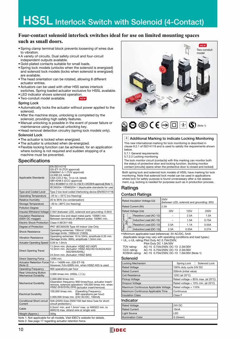
Four-contact solenoid interlock switches ideal for use on limited mounting spaces such as small doors. •Spring clamp terminal block prevents loosening of wires due to vibration. •A variety of circuits. Dual safety circuit and four-circuit independent outputs available. •Gold-plated contacts suitable for small loads. •Spring lock models (unlocks when the solenoid is energized) and solenoid lock models (locks when solenoid is energized) are available. •The head orientation can be rotated, allowing 8 different actuator entries. •Actuators can be used with other HS5 series interlock switches. Spring loaded actuator exclusive for HS5L available. • LED indicator shows solenoid operation. •Two-conduit model available.
Spring Lock •Automatically locks the actuator without power applied to the solenoid. •After the machine stops, unlocking is completed by the solenoid, providing high safety features. •Manual unlocking is possible in the event of power failure or maintenance using a manual unlocking key. •Head removal detection circuitry (spring lock models only).
Solenoid Lock •The actuator is locked when energized. •The actuator is unlocked when de-energized. •Flexible locking function can be achieved, for an application where locking is not required and sudden stopping of a machine must be prevented.
Specifications
Applicable Standards
EN ISO14119GS-ET-19 (TÜV approval)EN60947-5-1 (TÜV approval)UL508 (UL listed)CSA C22.2 No. 14 (c-UL listed)GB14048.5 (CCC approval)KS C IEC60947-5-1/S1-G-1/S2-E-4 (KOSHA approval) (Note 1)IEC60204-1/EN60204-1 (Applicable standards for use)
Type and Coded Level Type 2 low level coded interlocking device (EN/ISO14119)
Operating Temperature –25 to + 55°C (no freezing)
Relative Humidity 20 to 95% (no condensation)
Storage Temperature –40 to +80°C (no freezing)
Pollution Degree 3
Impulse Withstand Voltage 2.5kV (between LED, solenoid and grounding: 0.5kV)
Insulation Resistance (500V DC megger)
Between live and dead metal parts: 100MΩ min.Between terminals of different poles: 100MΩ min.
Electric Shock Protection Class II (IEC61140)
Degree of Protection IP67 (IEC60529) Type 4X Indoor Use Only
Shock Resistance Operating extremes: 100m/s2 (10G) Damage limits: 1000m/s2 (100G)
Vibration Resistance Operating extremes: 10 to 55Hz, amplitude 0.35 min.Damage limits: 30Hz, amplitude 1.5mm min.
Actuator Operating Speed 0.05 to 1.0m/s
Direct Opening Travel
11.0mm min. (Actuator: HS9Z-A51/A5P)12.0mm min. (Actuator: HS9Z-A52/A51A/A52A/A53/ A55/SH5/EH5L)24.5mm min. (Actuator: HS9Z-BA5)
Direct Opening Force 120N min.Actuator Retention Force (Note 2)
Fzh = 1400N min. (GS-ET-19)However, Fzh=500N min. when HS9Z-A55 is used
Operating Frequency 900 operations per hourRear Unlocking ButtonMechanical Durability 3,000 times min. (HS5L-L)
Mechanical Durability
2,000,000 times min.(Operation frequency 900 times/hour, actuator insert/remove, solenoid operation) 100,000 times min. when HS9Z-SH5/EH5L/DH5 (actuator insert/remove)
Electrical Durability100,000 times min. (Operating Frequency: 900 operations per hour)2,000,000 times min. (24V AC/DC, 100mA)
Conditional Short-circuit Current
50A (250V) (Use 250V/10A fast-blow fuse for short- circuit protection.)
Cable 0.3mm2 min. and 1.5mm2 max. or AWG22 min. to AWG16 max. strand wire or single wire
Weight (Approx.) 300g
Note 1: Not applicable for all models. Visit IDEC’s website for details.Note 2: See page 17 regarding actuator retention force.
RatingsContact Ratings
Rated Insulation Voltage (Ui) 250V(between LED, solenoid and grounding: 30V)
Rated Current (Ith) 2.5A
Rated Voltage (Ue) 30V 125V 250V
Rat
ed C
urre
nt
(Ie)∗
ACResistive Load (AC-12) − 2.5A 1.5A
Inductive Load (AC-15) − 1.5A 0.75A
DCResistive Load (DC-12) 2.5A 1.1A 0.55A
Inductive Load (DC-13) 2.3A 0.55A 0.27A
•Minimum applicable load (reference): 3V AC/DC, 5mA (Applicable range may vary with operating conditions and load types.)
∗ UL, c-UL rating: Pilot Duty AC 0.75A/250V, Pilot Duty DC 1.0A/30V TÜV rating: AC-15 0.75A/250V, DC-13 2.3A/30V CCC rating: AC-15 0.75A/250V, DC-13 2.3A/30V KOSHA rating: AC-15 0.75A/250V, DC-13 1.0A/30V (Note 1)
SolenoidLocking Mechanism Spring Lock Solenoid Lock
Rated Voltage 100% duty cycle 24V DC
Rated Current 200mA (initial value)
Coil Resistance 120Ω (at 20°C)
Pickup Voltage Rated voltage × 85% max. (at 20°C)
Dropout Voltage Rated voltage × 10% min. (at 20°C)
Maximum Continuous Applicable Voltage Rated voltage × 110%
Maximum Continuous Applicable Time Continuous
Insulation Class Class F
IndicatorRated Voltage 24V DC
Rated Current 10mA
Light Source LED
Illumination Color G (Green)
Additional Marking to indicate Locking MonitoringThis new international marking for lock monitoring is described in clause 9.2.1 of ISO14119 and is used to satisfy the requirements shown below.5.7.1 General requirements5.7.2.2 Locking monitoringThe lock monitor circuit (contacts) with this marking can monitor both the status of protective door and locking function. (locking monitor contact [circuits] opens when the protective door is closed and locked)
Both spring lock and solenoid lock models of HS5L have marking for lock monitoring. Note that solenoid lock model can be used in applications where lock for safety purpose is found unnecessary after a risk assess-ment, e.g. locking is needed for purposes such as in production process.
(Note 1)
Two-conduit model
10

11
HS5L Interlock Switches with Solenoid (4-Contact)4-Contact (Spring Lock/Solenoid Lock) Package Quantity: 1
Circuit Code Contact Configuration Gland Port Size
Spring lock Solenoid
Part No.
VA
M20
HS5L-VA44M-G HS5L-VA7Y4M-G
VB
HS5L-VB44M-G HS5L-VB7Y4M-G
VC
HS5L-VC44M-G HS5L-VC7Y4M-G
VD
HS5L-VD44M-G
HS5L-VD7Y4M-G
HS5L-VD44SM-G
VF
HS5L-VF44M-G HS5L-VF7Y4M-G
VG
HS5L-VG44M-G HS5L-VG7Y4M-G
VJ HS5L-VJ44M-G HS5L-VJ7Y4M-G
• The contact configuration shows the status when the actuator is inserted and the switch is locked. • Actuators are not supplied with the interlock switch and must be ordered separately. • For safety circuit input, connect to the monitor circuit with marking. • Contact us for details of two-conduit model. (Part No: HS5L-SM-G)
Note: Both spring lock and solenoid lock models of HS5L have marking for lock monitoring. Note that solenoid lock model can be used in applications where lock for safety purpose is found unnecessary after a risk assessment, e.g. locking is needed for purposes such as in production process.
HS5L Interlock Switch with Solenoid (4-Contact)
Door Monitor: 1NC, 1NO
Door Monitor: 1NC, 1NO
Door Monitor: 2NC
Door Monitor: 2NC
Door Monitor: 3NC
Door Monitor: 2NC, 1NO
Door Monitor: 1NC
Monitor Circuit:
Monitor Circuit:
Monitor Circuit:
Monitor Circuit:
Monitor Circuit:
Monitor Circuit:
Monitor Circuit:
Monitor Circuit:
34332221
31 322221
2221
11 12
1211
11 12
122111
22
122311
24
23 24
5251
4241
41 42
4241
53 54
41 42
(–)
53 54
(+)
41 42
A2 A1
Monitor Circuit:
Monitor Circuit:
Monitor Circuit:
Monitor Circuit:Monitor Circuit:
Monitor Circuit:
Monitor Circuit:Monitor Circuit:
Monitor Circuit:Monitor Circuit:
41 421211
5251
(Note)
(Note)
(Note)
(Note)
(Note)
(Note)
Monitor Circuit:
Monitor Circuit: 11 1252514241
Monitor Circuit:(Note)
(Note)6463
(Note)
(Note)
Door Monitor(Actuator inserted)
Lock MonitorSpring lock→Solenoid OFF
Solenoid lock→Solenoid ON
Lock Monitor Circuit: 1NC,1NO
Lock Monitor Circuit: 2NC
Lock Monitor Circuit: 1NC,1NO
Lock Monitor Circuit: 2NC
Lock Monitor Circuit: 1NC
Lock Monitor Circuit: 1NC
Lock Monitor Circuit: 2NC, 1NO

12
4-Contact/Rear Unlocking Button (Spring Lock) Package Quantity: 1
Circuit Code Contact Configuration Gland Port Size
Spring lock
Part No.
VA
Monitor Circuit:
Monitor Circuit:
Monitor Circuit:
Monitor Circuit:
Monitor Circuit:
Monitor Circuit:
52512221
11 12 4241
53 54
41 42122111
22
53 54
41 42122311
24
A2 A1
Monitor Circuit:
Monitor Circuit:
Monitor Circuit:
23 24Monitor Circuit:
Monitor Circuit:Monitor Circuit:
41 421211
5251
Door Monitor(Actuator inserted)
Lock Monitor(Solenoid OFF)(+) (–)
Door Monitor Circuit: 1NC,1NO Lock Monitor Circuit: 1NC,1NO
M20
HS5L-VA44LM-G
VB
Door Monitor Circuit: 1NC,1NO Lock Monitor Circuit: 2NC
HS5L-VB44LM-G
VC
Door Monitor Circuit: 2NC Lock Monitor Circuit: 1NC,1NO
HS5L-VC44LM-G
VD
Door Monitor Circuit: 2NC Lock Monitor Circuit: 2NC
HS5L-VD44LM-G
• The contact configuration shows the status when the actuator is inserted and the switch is locked. • Actuators are not supplied with the interlock switch and must be ordered separately.
4-Contact/Dual Safety Circuit (Spring Lock) Package Quantity: 1
Circuit Code Contact Configuration Gland Port Size
Spring lock
Part No.
DD
Main Circuit: 1NC+1NC1NC+1NC
A1A2(+) (–)
Main Circuit: 11 12 424121Main Circuit: 525122
Door Monitor(Actuator inserted)
Lock Monitor(Solenoid OFF)
M20
HS5L-DD44M-G
HS5L-DD44SM-G (two-conduit model)
• The contact configuration shows the status when the actuator is inserted and the switch is locked. • Actuators are not supplied with the interlock switch and must be ordered separately.
4-Contact/Dual Safety Circuit/Rear Unlocking Button (Spring Lock) Package Quantity: 1
Circuit Code Contact Configuration Gland Port Size
Spring lock
Part No.
DD
Main Circuit: 1NC+1NC1NC+1NC
A1A2(+) (–)
Main Circuit: 11 12 424121Main Circuit: 525122
Door Monitor(Actuator inserted)
Lock Monitor(Solenoid OFF)
M20
HS5L-DD44LM-G
HS5L-DD44LSM-G (two-conduit model)
• The contact configuration shows the status when the actuator is inserted and the switch is locked. • Actuators are not supplied with the interlock switch and must be ordered separately.
HS5L Interlock Switch with Solenoid (4-Contact)
13
HS5L Interlock Switch with Solenoid (4-Contact)
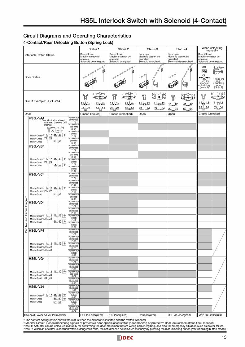
Circuit Diagrams and Operating Characteristics4-Contact/Rear Unlocking Button (Spring Lock)
Interlock Switch Status
Status 1 Status 2 Status 3 Status 4
Door ClosedMachine ready to operateSolenoid de-energized
Door ClosedMachine cannot be operatedSolenoid energized
Door openMachine cannot be operatedSolenoid energized
Door openMachine cannot be operatedSolenoid de-energized
Door Status
Circuit Example: HS5L-VA411
23
42
54
12
24
41
53
A2 A1(+) (–)
A1A2
53
41
24
12
54
42
23
11
(+) (–)
11
23
42
54
12
24
41
53
A2 A1(+) (–)
A1A2
53
41
24
12
54
42
23
11
(+) (–)
Door Closed (locked) Closed (unlocked) Open Open
Par
t N
o. a
nd C
ircui
t D
iagr
am
HS5L-VA4
Monitor Circuit(door closed)
11−12Monitor Circuit
(door open)23−24
Monitor Circuit(locked)41−42
Monitor Circuit(unlocked)
53−54
HS5L-VB4 Monitor Circuit(door closed)
11−12Monitor Circuit
(door open)23−24
Monitor Circuit(locked)41−42
Monitor Circuit(locked)51−52
HS5L-VC4 Monitor Circuit(door closed)
11−12Monitor Circuit(door closed)
21−22Monitor Circuit
(locked)41−42
Monitor Circuit(unlocked)
53−54
HS5L-VD4 Monitor Circuit(door closed)
11−12Monitor Circuit(door closed)
21−22Monitor Circuit
(locked)41−42
Monitor Circuit(locked)51−52
HS5L-VF4 Monitor Circuit(door closed)
11−12Monitor Circuit(door closed)
21-22Monitor Circuit(door closed)
31-32Monitor Circuit
(locked)41-42
HS5L-VG4 Monitor Circuit(door closed)
11−12Monitor Circuit(door closed)
21-22Monitor Circuit
(door open)33-34
Monitor Circuit(door locked)
41-42
HS5L-VJ4 Monitor Circuit(door closed)
11-12Monitor Circuit
(locked)41-42
Monitor Circuit(locked)51-52
Monitor Circuit(door locked)
63-64
Solenoid Power A1-A2 (all models) OFF (de-energized) ON (energized) ON (energized) OFF (de-energized)
Monitor Circuit:
Monitor Circuit:
Monitor Circuit:
Monitor Circuit:
Monitor Circuit:
Monitor Circuit:
Monitor Circuit:
Monitor Circuit:Monitor Circuit:
Monitor Circuit:
Monitor Circuit:
Monitor Circuit:Monitor Circuit:
Monitor Circuit:Monitor Circuit:
53
41
5251
4241
41 42
4241
53 54
41 42
54
42122311
24
34332221
31 322221
2221
11 12
1211
11 12
122111
22
Monitor Circuit:Monitor Circuit:Monitor Circuit: 12
2311
24
Monitor Circuit:
Monitor Circuit:Monitor Circuit:
424111 1252516463
5251
4241
A2 A1
Door Monitor(Actuator inserted)
Lock Monitor(Solenoid OFF)
(+) (–)
When unlocking manually
Door ClosedMachine cannot be operatedSolenoid de-energized
Press
·Turn themanual
unlock key(Note 1)
·Press therear
unlockingbutton
(Note 2)
Press
·Turn themanual
unlock key(Note 1)
·Press therear
unlockingbutton
(Note 2)
11
23
42
54
12
24
41
53
A2 A1(+) (–)
Closed (unlocked)
OFF (de-energized)
•The contact configuration shows the status when the actuator is inserted and the switch is locked.•Monitor Circuit: Sends monitoring signals of protective door open/closed status (door monitor) or protective door lock/unlock status (lock monitor).Note 1: Actuator can be unlocked manually for confirming the door movement before wiring and energizing, and also for emergency situation such as power failure.Note 2: When an operator is confined within a dangerous zone, the actuator can be unlocked manually by pressing the rear unlocking button (rear unlocking button model).

14
HS5L Interlock Switch with Solenoid (4-Contact)
•The operation characteristics shown in the chart above are for HS9Z-A51. For other actuators, add 1.3mm.•See page 24 for HS9Z-BA5.•The operation characteristics show the contact status when the actuator enters the entry slot of an interlock switch.
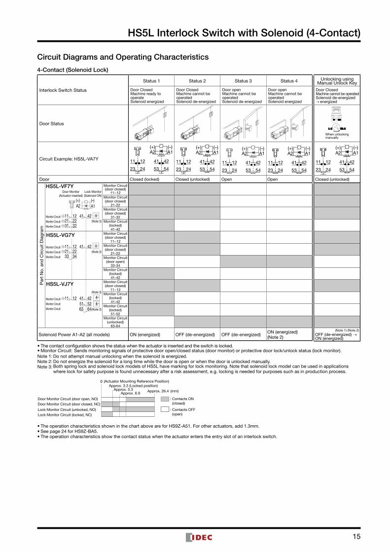
Circuit Diagrams and Operating Characteristics
4-Contact (Solenoid Lock)
Interlock Switch Status
Status 1 Status 2 Status 3 Status 4
Door ClosedMachine ready to operateSolenoid energized
Door ClosedMachine cannot be operatedSolenoid de-energized
Door openMachine cannot be operatedSolenoid de-energized
Door openMachine cannot be operatedSolenoid energized
Door Status
Circuit Example: HS5L-VA7Y 11
23
42
54
12
24
41
53
A2 A1(+) (–)
A1A2
53
41
24
12
54
42
23
11
(+) (–)
11
23
42
54
12
24
41
53
(+)A2
(–)A1 A1A2
53
41
24
12
54
42
23
11
(+) (–)
Door Closed (locked) Closed (unlocked) Open Open
Par
t N
o. a
nd C
ircui
t D
iagr
am
HS5L-VA7Y
Monitor Circuit:
Monitor Circuit:
Monitor Circuit:
Monitor Circuit:
Monitor Circuit:
Monitor Circuit:
Monitor Circuit:
Monitor Circuit:
Monitor Circuit:
53
41
5251
4241
53 54
41 42
54
42122311
24
222111 12
122111
22
Monitor Circuit:
Monitor Circuit:
Monitor Circuit: 122311
245251
4241
(–)(+)A2 A1
(Note 3)
(Note 3)
(Note 3)
(Note 3)
(Note 3)
(Note 3)
Door Monitor(Actuator inserted)
Lock Monitor(Solenoid ON)
Monitor Circuit(door closed)
11−12Monitor Circuit
(door open)23−24
Monitor Circuit(locked)41−42
Monitor Circuit(unlocked)
53−54Monitor Circuit(door closed)
11−12Monitor Circuit
(door open)23−24
Monitor Circuit(locked)41−42
Monitor Circuit(locked)51−52
Monitor Circuit(door closed)
11−12Monitor Circuit(door closed)
21−22Monitor Circuit
(locked)41−42
Monitor Circuit(unlocked)
53−54Monitor Circuit(door closed)
11−12Monitor Circuit(door closed)
21−22Monitor Circuit
(locked)41−42
Monitor Circuit(locked)51−52
Solenoid Power A1-A2 (all models) ON (energized) OFF (de-energized) OFF (de-energized) ON (energized) (Note 2)
Unlocking using Manual Unlock Key
Door ClosedMachine cannot be operatedSolenoid de-energized ➝ energized
When unlockingmanually
11
23
42
54
12
24
41
53
A2 A1(+) (–)
Closed (unlocked)
(Note 1) (Note 2)
OFF (de-energized) ➝ ON (energized)
•The contact configuration shows the status when the actuator is inserted and the switch is locked.•Monitor Circuit: Sends monitoring signals of protective door open/closed status (door monitor) or protective door lock/unlock status (lock monitor).Note 1: Do not attempt manual unlocking when the solenoid is energized.Note 2: Do not energize the solenoid for a long time while the door is open or when the door is unlocked manually.Note 3: Both spring lock and solenoid lock models of HS5L have marking for lock monitoring. Note that solenoid lock model can be used in applications
where lock for safety purpose is found unnecessary after a risk assessment, e.g. locking is needed for purposes such as in production process.
Approx. 26.4 (mm) Approx. 5.3 Approx. 6.9
: Contacts OFF (open)
: Contacts ON (closed)
Lock Monitor Circuit (unlocked, NO)
Door Monitor Circuit (door open, NO)
Lock Monitor Circuit (locked, NC)
Door Monitor Circuit (door closed, NC)
Approx. 3.3 (Locked position)0 (Actuator Mounting Reference Position)
HS5L-VB7Y
HS5L-VC7Y
HS5L-VD7Y
15
HS5L Interlock Switch with Solenoid (4-Contact)
•The operation characteristics shown in the chart above are for HS9Z-A51. For other actuators, add 1.3mm.•See page 24 for HS9Z-BA5.•The operation characteristics show the contact status when the actuator enters the entry slot of an interlock switch.
•The contact configuration shows the status when the actuator is inserted and the switch is locked.•Monitor Circuit: Sends monitoring signals of protective door open/closed status (door monitor) or protective door lock/unlock status (lock monitor).Note 1: Do not attempt manual unlocking when the solenoid is energized.Note 2: Do not energize the solenoid for a long time while the door is open or when the door is unlocked manually.Note 3: Both spring lock and solenoid lock models of HS5L have marking for lock monitoring. Note that solenoid lock model can be used in applications
where lock for safety purpose is found unnecessary after a risk assessment, e.g. locking is needed for purposes such as in production process.
Approx. 26.4 (mm) Approx. 5.3 Approx. 6.9
: Contacts OFF (open)
: Contacts ON (closed)
Lock Monitor Circuit (unlocked, NO)
Door Monitor Circuit (door open, NO)
Lock Monitor Circuit (locked, NC)
Door Monitor Circuit (door closed, NC)
Approx. 3.3 (Locked position)0 (Actuator Mounting Reference Position)
Circuit Diagrams and Operating Characteristics
4-Contact (Solenoid Lock)
Interlock Switch Status
Status 1 Status 2 Status 3 Status 4
Door ClosedMachine ready to operateSolenoid energized
Door ClosedMachine cannot be operatedSolenoid de-energized
Door openMachine cannot be operatedSolenoid de-energized
Door openMachine cannot be operatedSolenoid energized
Door Status
Circuit Example: HS5L-VA7Y 11
23
42
54
12
24
41
53
A2 A1(+) (–)
A1A2
53
41
24
12
54
42
23
11
(+) (–)
11
23
42
54
12
24
41
53
(+)A2
(–)A1 A1A2
53
41
24
12
54
42
23
11
(+) (–)
Door Closed (locked) Closed (unlocked) Open Open
Par
t N
o. a
nd C
ircui
t D
iagr
am
HS5L-VF7Y
Monitor Circuit:
Monitor Circuit:
Monitor Circuit:
Monitor Circuit:
Monitor Circuit:
Monitor Circuit:
4241
41 42
34332221
31 322221
11 12
1211
A2 A1
Monitor Circuit:
Monitor Circuit:
Monitor Circuit:
424111 1252516463
(–)(+)
(Note 3)
(Note 3)
(Note 3)
(Note 3)
Door Monitor(Actuator inserted)
Lock Monitor(Solenoid ON)
Monitor Circuit(door closed)
11−12Monitor Circuit(door closed)
21-22Monitor Circuit(door closed)
31-32Monitor Circuit
(locked)41-42
Monitor Circuit(door closed)
11−12Monitor Circuit(door closed)
21-22Monitor Circuit
(door open)33-34
Monitor Circuit(locked)41-42
Monitor Circuit(door closed)
11−12Monitor Circuit
(locked) 41-42
Monitor Circuit(locked) 51-52
Monitor Circuit(unlocked)
63-64
Solenoid Power A1-A2 (all models) ON (energized) OFF (de-energized) OFF (de-energized) ON (energized) (Note 2)
Unlocking using Manual Unlock Key
Door ClosedMachine cannot be operatedSolenoid de-energized ➝ energized
When unlockingmanually
11
23
42
54
12
24
41
53
A2 A1(+) (–)
Closed (unlocked)
(Note 1) (Note 2)
OFF (de-energized) ➝ ON (energized)
HS5L-VG7Y
HS5L-VJ7Y

16
HS5L Interlock Switch with Solenoid (4-Contact)
0
Approx. 26.4 Approx. 5.3
Approx. 6.9
Approx. 3.3 (Locked position)
(Stroke: mm)
(Actuator insertion position)
: Contacts OFF (open)
: Contacts ON (closed)
Main Circuit
Circuit Diagrams and Operating Characteristics
4-Contact/Dual Safety Circuit, 4-Contact/Dual Safety Circuit/Rear Unlocking Button (Spring Lock)
Interlock Switch Status
Status 1 Status 2 Status 3 Status 4
Door ClosedMachine ready to operateSolenoid de-energized
Door ClosedMachine cannot be operatedSolenoid energized
Door openMachine cannot be operatedSolenoid energized
Door openMachine cannot be operatedSolenoid de-energized
Door Status
Circuit Example: HS5L-DD4
A2 A1
5221
11 42
5122
12 41
(+) (–)A2 A1
52512221
11 12 4241
(+) (–)A2 A1
5221
11 42
5122
12 41
(+) (–)A2 A1
5221
11 42
5122
12 41
(+) (–)
Door Closed (locked) Closed (unlocked) Open Open
Par
t N
o. a
nd C
ircui
t D
iagr
am
HS5L-DD44
A1A2
Main Circuit: 11 12 424121Main Circuit: 525122
Main Circuit: 11 12 424121Main Circuit: 525122
Door Monitor(Actuator inserted)
Lock Monitor(Solenoid OFF)
(+) (–)
Main Circuit11−42
Main Circuit21−52
Main Circuit11−42
Main Circuit21−52
Solenoid Power A1-A2 (all model) OFF (de-energized) ON (energized) ON (energized) OFF (de-energized)
• The contact configuration shows the status when the actuator is inserted and the switch is locked. • Main Circuit: Connected to the control circuit of machine drive part, sending interlock signals of the protective door. • For safety circuit input, connect to the monitor circuit.
Note 1: Actuator can be unlocked manually for confirming the door movement before wiring and energizing, and also for emergency situation such as power failure.
Note 2: When an operator is confined within a dangerous zone, the actuator can be unlocked manually by pressing the rear unlocking button. (rear unlocking button model)
Operating Characteristics (Reference)
Unlocking using Manual Unlock Key
Door ClosedMachine cannot be operatedSolenoid de-energized
Press
·Turn themanual
unlock key(Note 1)
·Press therear
unlockingbutton
(Note 2)
Press
·Turn themanual
unlock key(Note 1)
·Press therear
unlockingbutton
(Note 2)
A2 A1
5221
11 42
5122
12 41
(+) (–)
Closed (unlocked)
OFF (de-energized)
• The operation characteristics shown in the chart above are of the HS9Z-A51. For other actuators, add 1.3mm. • See page 24 for HS9Z-BA5. • The operation characteristics show the contact status when the actuator enters the entry slot of an interlock switch.
HS5L-DD44L

ActuatorDescription Part No. Package Quantity Remarks
Straight HS9Z-A51
1
Actuator retention force is Fzh=1400N.
Straight with rubber bushings HS9Z-A51A
Right-angle HS9Z-A52
Right-angle with tubber bushings HS9Z-A52A
Angle adjustable (vertical) HS9Z-A53
Angle adjustable (vertical/horizontal) HS9Z-A55 Actuator retention force is Fz=500N. When a retention force of 500N or more is required, use HS9Z-A53.
Accessories Description Part No. Package Quantity Remarks
Sliding actuator (Note 1) (Note 2) HS9Z-SH5
1
Door handle actuator
Handle unit for right-hand door HS9Z-DH5RHChoose according to the required opening side.
Handle unit for left-hand door HS9Z-DH5LH
Switch cover unit HS9Z-DH5CUsed for installing the interlock switch inside.
Slide handle actuator HS9Z-EH5L
Spring loaded actuator (Note 2) (Note 3) HS9Z-BA5
Plug actuator HS9Z-A5P
Padlock hasp HS9Z-PH5
Mounting plate (Note 4) HS9Z-SP51 Used when installing the interlock switch on the aluminum frame.
Note 1: For specification on sliding actuators, see separate catalog.Note 2: Actuator retention force is Fzh=1400N.Note 3: HS9Z-BA5 can only be used for HS5L interlock switches. Also, HS9Z-BA5 can be used only on slide doors. Do not use on hinge doors.Note 4: When mounting HS5L-L (rear unlocking button model) using a mounting plate, provide mounting holes on the mounting plate as shown below
and user Rear Unlocking Button Kit (HS9Z-FL5 ).•Follow the instructions on catalog or instruction sheet for proper use of accessories.
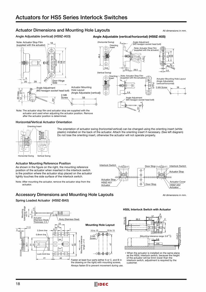
Actuators for HS5 Series Interlock Switches
Straight (HS9Z-A51)
Note: Actuator Stop(supplied with the actuator)
2615
32.4
28 20
4-R 2
.2
10
0.85.2(6)
6.2
6.4
2
2-M4 Screw 20
Actuator Mounting Hole Layout (Straight, Right-angle)
Straight with Rubber Bushings (HS9Z-A51A)
30
7.3 43.815.3
15
2-ø4.3
2
120.
8(2
0)
0.8
2-ø10
2-ø9
Whe
nm
ount
ed (
5)
Washer (supplied)
Rubber Bushing
Note: Actuator Stop(supplied with the actuator)
∗ The mounting center distance is set to 12 mm at the factory. When a 20mm distance is required, adjust the distance by moving the rubber bushing sideways.
∗ The actuator has �exibility to the direction indicated by the arrows.
∗ Mounting centers can be widened to 20mm by moving the Rubber Bushings.
∗ Mounting centers must be 12 or 20mm.
VerticalSwing
Actuator Mounting Hole Layout(Straight with Rubber Bushings)(Right-angle with Rubber Bushings)
122-M4 Screw
Right-angle (HS9Z-A52) Right-angle with Rubber Bushings (HS9Z-A52A)
152
2-ø4.4
20
33
29.6
28
0.84.5
2 7.27.2
1.6
Note: Actuator Stop(supplied with the actuator)
Actuator Cover
VerticalSwing
HorizontalSwing
∗ When the mounting center distance is set to 12mm at the factory, the actuator has �exibility both vertically and horizontally.
∗ When the mounting center distance is set to 20mm, the actuator swings vertically.Adjust the distance by moving the rubber bushings.
30 15
15.8
8.5
0.8
2
0.8
(11.2)
When mounted (39.7)When
mounted
Whenmounted
(5)
2-ø9
2-ø1
0
2-ø4
.312(20)
Note: Actuator Stop(supplied with the actuator)
Rubber Bushing Washer (supplied)
∗ Mounting centers must be 12 or 20mm.
Actuator Dimensions and Mounting Hole Layouts All dimensions in mm.
17
18
Horizontal/Vertical Actuator OrientationOrienting Insert
Horizontal Swing Vertical Swing
The orientation of actuator swing (horizontal/vertical) can be changed using the orienting insert (white plastic) installed on the back of the actuator. Attach the orienting insert if necessary. (See left diagram) Do not lose the orienting insert, otherwise the actuator will not operate properly.
Actuator Mounting Reference Position
HS9Z-A52Actuator
Actuator Cover
Actuator Stop
Interlock Switch
Door StopHS9Z-A51Actuator
Actuator Stop
Interlock Switch Door StopAs shown in the figure on the right, the mounting reference position of the actuator when inserted in the interlock switch is the position where the actuator stop placed on the actuator lightly touches the side surface of the interlock switch.
Note: After mounting the actuator, remove the actuator stop from the actuator.
Accessory Dimensions and Mounting Hole Layouts All dimensions in mm.
Spring Loaded Actuator (HS9Z-BA5)
Mounting Hole Layout
HS5L Interlock Switch with Actuator
Body (Stainless Steel)
7
2.5
715
7
23
5
1531
41 40
58
11.33
35.1
47
3.3mm line
0.8mm line
Lock limit line
Mou
ntin
g to
lera
nce
rang
e: ±
1.0
±0.
75
6-M5Screw
10 to 15 10 to 15
47
∗ When the actuator is installed on the same plane as the HS5L interlock switch, because the height of the actuator will be 5mm lower than the interlock switch, adjustment is required by the customer.
0.8
(Mounting tolerance range: 0.8 )+2.5 0
∗5±
0.5
(Hei
ght a
djus
tmen
t)
86.5 36.2
47
20 t
o 22
AB
C57
Actuator(Stainless Steel)Thickness: 2.5
Mou
ntin
gto
lera
nce
rang
e
Fasten at least four parts (either A or C, and B in the drawing on the right) with mounting screws.Always fasten B to prevent movement during use.
Actuators for HS5 Series Interlock Switches
Actuator Dimensions and Mounting Hole Layouts All dimensions in mm.
205
R3.2
725844
33 m
ax.
12(2
1)1
20°
29
582-M6Screw
18
Actuator MountingHole Layout(Angle Adjustable [vertical])
Angle Adjustment(M3 hexagon socket head bolt)
Door HingeSide
Note: Actuator Stop Film(supplied with the actuator)
(M4 Hole)
R2.1
20°
20°
Note: Actuator Stop Film(supplied with the actuator)
Note: Actuator Stop Film(supplied with the actuator)
Angle Adjustment(M3 hexagon socket head bolt)
Angle Adjustment(M3 hexagon socket head bolt)
(Horizontal Swing)
(Vertical Swing)
OrientingInsert
OrientingInsert
2-M4 Screw
48.4
14.4 718.5 28.5
3
3.6
1
23 26 38
38
0.8
2
Actuator Mounting Hole Layout(Angle Adjustable)(vertical/horizontal)
Note: The actuator stop film and actuator stop are supplied with the actuator and used when adjusting the actuator position. Remove after the actuator position is determined.
Angle Adjustable (vertical) (HS9Z-A53) Angle Adjustable (vertical/horizontal) (HS9Z-A55)

19
HS5L Interlock Switches with Solenoid
Interlock Switch Dimensions and Mounting Hole Layouts All dimensions in mm.
Manual Unlock
10 to 11
20 to 22
(with Indicator)
3-M4 Screw
36.2
944
.5
127
R2.2
20 11
5.2
6.2
42.2
61.6
511
35
3086
.5
LED
10 1
20
40
86.5
Mounting Hole Layout
3
617
.8
33
Manual Unlocking Key
3(2
4 )9
15
18 6.5(24.5)
16.8 43.
9
Accessories
Slot Plug
(supplied)
HS5L-4M-GWhen using Horizontal Mounting/Straight Actuator (HS9Z-A51)
HS5L-4SM-G (two-conduit model)When using Horizontal Mounting/Straight Actuator (HS9Z-A51)
36.2
944
.5
154.
2
R2.2
20 11
5.2
6.2
42.2
35
30
106
10 1
20
40
3.6
92.8
22.5
36.2
944
.5
154.
2
R2.2
20 11
5.2
6.2
42.2
61.6
511
35
30
106
101
20
40
3.6
6
92.8
17.5
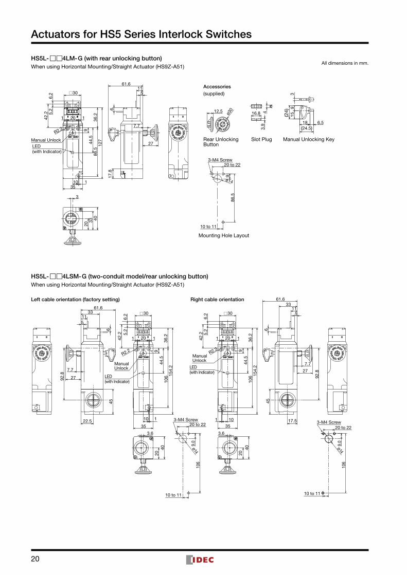
Left cable orientation (factory setting) Right cable orientation
511
61.6
6
3333
45
45
106
106
10 to 1110 to 11
Mounting Hole Layout Mounting Hole Layout
Manual Unlock
(with Indicator)LED
Manual Unlock
(with Indicator)LED
20 to 223-M4 Screw
20 to 223-M4 Screw
20
61.6
511
20
40
7.7
27
3
36.2
944
.5
127
R2.2
20 11
5.2
6.2
42.2
35
86.5
10 1
6
33
17.8
3(2
4)9
15
18 6.5(24.5)
16.8 43.
9
ø3012.5
Manual Unlock
(with Indicator)
30
LED
Mounting Hole Layout
Manual Unlocking KeySlot PlugRear UnlockingButton
86.5
10 to 119
ø14
Accessories(supplied)
20 to 223-M4 Screw
All dimensions in mm.HS5L-4LM-G (with rear unlocking button)When using Horizontal Mounting/Straight Actuator (HS9Z-A51)
HS5L-4LSM-G (two-conduit model/rear unlocking button)When using Horizontal Mounting/Straight Actuator (HS9Z-A51)
36.2
944
.5
154.
2
R2.2
11
5.2
6.2
42.2
35
30
106
10 1
2040
3.6
92.8
22.5
36.2
944
.5
154.
2
R2.2
11
5.2
6.2
42.2
61.6
511
35
106
101
2040
3.6
6
92.8
17.5
7.7
27
511
61.633
27
7.7
6
33
45 45
106
9.0
ø14
106
10 to 11
9.0
ø14
ManualUnlock
ManualUnlock
(with Indicator)LED
(with Indicator)LED
Left cable orientation (factory setting) Right cable orientation
30
20 to 22
10 to 11
3-M4 Screw
20 to 223-M4 Screw
20 20
Actuators for HS5 Series Interlock Switches

21
Accessories
Description Part No. Package QuantityPanel Thickness ∗ (X)
HS5L Interlock Switch Rear Unlocking Button Kit(When mounting HS5L-L directly)
Rear Unlocking Button Kit
HS9Z-FL53
1
23 < X ≤ 33
HS9Z-FL54 33 < X ≤ 43
HS9Z-FL55 43 < X ≤ 53
DimensionsRear Unlocking Button Kit (HS9Z-FL5)
Note: With the mounting hole dimension, the rear unlocking button rod does not touch the mounting hole even when the interlock switch moves sideways.
All dimensions in mm.
ø40
ø10.
4
3325
.9
60.9
7360
.9
33
16
30
31.5 25.9
40
ø22 to 30
Rear Unlocking
Button Hole (N
ote)
16 to 30
M5 Screws
Button (PA66)
Panel Thickness (X): 23 to 53
Pin (Stainless Steel)
Link Rod (Stainless Steel)
Screw (Iron)
Hinge + Plate (SUS)
Button released
Button pressed(unlocked)
HS5LInterlock Switch(sold separately)
Rear Unlocking Button KitMounting Hole Layout
5-M4 Screws
When using the rear unlocking button kit,provide a rear unlocking button hole onthe HS9Z-SP51.
ø18 Rear UnlockingButton Hole (Note)
(40)
(22)
9.0
59.7
(187
)
170
187
4-R6.4
4-C3
106
86.5
50.7
42.2
2-12
.82-
6.6
6
22
40
5-M4
10
4-R3.3
22
Mounting Plate (HS9Z-SP51)Drilling Rear Unlocking Button Hole
HS5L Interlock Switches with Solenoid

22
HS5L Interlock Switches with Solenoid
Safety Precautions • In order to avoid electric shock or fire, turn power off before installation, removal, wiring, maintenance, or inspection of the interlock switch. • If relays are used in the circuit between the interlock switch and the load, use only safety relays, since welded or sticking contacts of standard relays may invalidate the functions of the interlock switch. Perform a risk assessment and make a safety circuit which satisfies the requirements of the safety category. • Do not place a PLC in the circuit between the interlock switch and the load. Safety security can be endangered in the event of a malfunction of the PLC. • Do not disassemble or modify the interlock switch, otherwise a malfunction or an accident may occur. • Do not install the actuator in a location where a human body may come into contact. Otherwise injury may occur. • Solenoid lock is locked when energized, and unlocked when de-energized. When energization is interrupted due to wire disconnection or other failures, the interlock switch may be unlocked causing possible danger to the operators. Solenoid lock must not be used in applications where locking is strictly required for safety. Perform a risk assessment and determine whether solenoid lock is appropriate. • When changing the head orientation, disconnect the cable and turn the manual unlock to the UNLOCK position in advance. If the head orientation is changed when the cable is connected and the manual unlock is in the LOCK position, machines may start to operate, causing danger to the operators.
• HS5L interlock switches are Type 2 low level coded interlocking devices (ISO14119). According to ISO14119, the following is required to minimize defeat when installing and constructing systems:
1. Prevent dismantling or de-positioning of the elements of the interlocking device by use of non-detachable fixing (e.g. welding, gluing, one-way screws, riveting). However, use of non-detachable fixing can be an inappropriate solution in cases where a failure of the interlocking device during lifetime of the machinery can be expected and a fast change is necessary. In this case measures mentioned below, should be used to provide the required level of risk reduction.
2. Apply at least one out of the four measures below.➀ Mounting out of reach.➁ Physical obstruction or shielding.➂ Mounting in hidden position.➃ Integration of defeat monitoring by means of status
monitoring/cyclic testing.
•Do not use the interlock switch as a door stop. Install a mechanical door stop at the end of the door to protect the interlock switch against excessive force. •Do not apply excessive shock to the interlock switch when opening or closing the door. A shock to the interlock switch exceeding 1,000m/s2 may cause damage to the interlock switch. •Prevent foreign objects such as dust and liquids from entering the interlock switch while connecting a conduit or wiring. •Plug the unused actuator entry slot using the slot plug supplied with the interlock switch. •Do not store the interlock switches in a dusty, humid, or organic-gas atmosphere, or in an area subjected to direct sunlight. •Use proprietary actuators only. When other actuators are used, the interlock switch may be damaged. •The locking strength is rated at 1400N. Do not apply a load higher than the rated value. When a higher load is expected, provide an additional system consisting of another interlock switch without lock (such as the HS5D interlock switch) or a sensor to detect door opening and stop the machine. •Regardless of door types, do not use the interlock switch as a door lock. Install a separate lock using a latch or other measures. •While the solenoid is energized, the switch temperature rises approximately 40°C above the ambient temperature (to approximately 95°C while the ambient temperature is 55°C). To prevent burns, avoid touching. If cables come into contact with the switch, use heat-resistant cables. •Although the HS9Z-A51A/A52A actuators alleviate shock when the actuator enters a slot in the interlock switch, make sure that excessive shock is not applied. If the Rubber Bushings become deformed or cracked, replace with new ones.
Mounting ExamplesRefer to the following drawing for the installation. Mount the interlock switch to a fixed machine or guard, and actuator on the hinged door. Do not mount both interlock switch and actuator on the hinged doors. This may result in the actuator being inserted at a wrong angle to the interlock switch, resulting in malfunction.
Application of Sliding Doors
Door
HS9Z-A51Actuator
HS5LInterlockSwitch
Latch
Door Stop
Door Door
HS9Z-A52Actuator
HS9Z-A51ActuatorHS5L
Interlock Switch
HS5LInterlock Switch
Latch
Application of Hinged Doors
Instructions

23
HS5L Interlock Switches with Solenoid
Instructions
Minimum Radius of Hinged DoorWhen using the interlock switch for a hinged door, refer to the minimum radius of doors shown below. Especially for doors with a small turning radius, use vertical/horizontal movable actuators (HS9Z-A53/A55).Note: Because deviation or dislocation of a hinged door may occur in actual
applications, make sure of the correct operation by installing the actual machine first before use.
HS9Z-A52 ActuatorWhen the center of the hinged door is used as the reference for the interlock switch contact surface:
Door Hinge Door Hinge
Interlock SwitchMounting Hole190m
m
170mm
Minim
um Radius
Minim
um R
adius
(161
)
(35)(36.2)
When the center of the hinged door is used as the reference for the actuator mounting surface:
230mm
260mm
(41.5) (40.3)
(231
)
Door Hinge Door Hinge
Interlock SwitchMounting HoleM
inimum
Radius
Minim
um R
adius
HS9Z-A52A Actuator (with Rubber Bushings)When the center of the hinged door is used as the reference for the interlock switch contact surface:
Centers 12m
m: 120m
m
Centers 20m
m: 170m
m
140mm
(36.2)
(111
)
(35)
Door Hinge Door Hinge
Interlock SwitchMounting HoleM
inimum
Radius
Minim
um Radius
When the center of the hinged door is used as the reference for the actuator mounting surface:
Centers 12m
m: 230m
m
Centers 20m
m: 310m
m
260mm
(231
)
(47)(48.2)
Door Hinge Door Hinge
Interlock SwitchMounting HoleM
inimum
Radius
Minim
um R
adius
Actuator Angle Adjustment (vertical/horizontal) • Using the angle adjustment screw, the actuator angle can be adjusted (refer to the dimensional drawing on page 17). Adjustable angle: 0 to 20° • The larger the adjusted angle of the actuator, the smaller the applicable radius of the door opening. After installing the actuator, open the door. Then adjust the actuator so that its edge can be inserted properly into the actuator entry slot of the interlock switch. • After adjusting the actuator angle, apply Loctite to the adjustment screw so that the screw will not move.
When using the HS9Z-A53 Angle Adjustable (vertical) Actuator • When the center of the hinged door is used as the reference for the interlock switch contact surface: 50mm • When the center of the hinged door is used as the reference for the actuator mounting surface: 80mm • Angle adjustment screw recommended tightening torque: 0.8N·m.
50mm
(36.2)
(38)
80mm
(56.5)
(68)Door
HingeDoorHinge
InterlockSwitchMountingHole
InterlockSwitchMountingHole
Minimum Radius
Minimum Radius
When using the HS9Z-A55 Angle Adjustable (vertical/horizontal) Actuator • When the center of the hinged door is used as the reference for the interlock switch contact surface: 50mm • When the center of the hinged door is used as the reference for the actuator mounting surface: 70mm • The HS9Z-A55 angle adjustable actuator is made of glass-reinforced PA66 (66 nylon) and the angle adjustment screw is stainless steel. When using the screw locking agent, make sure that it is compatible with the base material.
When the center of the hinged door is used as the reference for the interlock switch contact surface:
50mm
(36.2)
(38)
Vertical Swing
50mm
(36.2)
Horizontal Swing
DoorHingeDoor
Hinge
InterlockSwitchMountingHoleMinimum
Radius
Minimum Radius
When the center of the hinged door is used as the reference for the actuator mounting surface:
70mm70mm
(55.5)(55.5)
(58)
Vertical SwingHorizontal Swing
Door HingeDoor Hinge
InterlockSwitchMountingHole
Minimum Radius
Minimum Radius

24
HS5L Interlock Switches with Solenoid
Instructions
Installing the HeadDo not use plastic and metallic heads of HS5D interlock switches on the HS5L. Be sure to use HS5L metallic heads. ∗ The metal heads of the HS5D and HS5L look similar. When using these interlock switches adjacently, ensure that the heads are not interchanged.
PlasticColor: Red
HS5LHS5D
Metallic HeadMetallic HeadPlastic Head
MetalColor: Silver
Color:Red∗
Color:Black∗
∗ The metal head can be distinguished easily by the color of the plastic.
Rotating the HeadThe head can be rotated by removing the four screws from the corners of the head and reinstalling the head in the desired orientation. However, when changing the mounting direction of the head after wiring, turn the manual lock release to the “UNLOCK” position using the enclosed manual lock release key first. When reinstalling the head, make sure that no foreign object enters the interlock switch. Tighten the screws tightly, without leaving a space between the head and body, otherwise the interlock switch may malfunction.(Recommended tightening torque: 0.9 to 1.1 N·m)
Factory Setting Head can be rotated
Head Removal Detection Function • Solenoid locks interlock switches are not equipped with the head removal detection function. • The head removal detection function is available only on spring lock interlock switches with circuits VB, VD, and DD having two or more lock monitor circuits. Removing the head will result in disparity (41-42: OFF, 51-52: ON). Note that this function cannot be detected with other models. • Only the lock monitor circuit 41-42 turns off (open) when the head is removed, such as when the head is rotated. The other monitor circuit 51-52 turns ON (close). Be sure to connect the lock monitor circuit (41-42) to a safety circuit.
Spring Loaded Actuator • When using the actuator, be careful of protruding ends. • Regardless of door types, do not use the HS9Z-BA5 actuator as a door lock or a door stop. • When an operator enters the hazardous zone, take safety measures such as using a HS9Z-PH5 padlock hasp so that the operator is not trapped inside and the machine cannot start by mistake. • Use the actuator only on sliding doors. Do not use on hinged doors. • As shown in the figure on the right, do not insert the sliding actuator from below. The actuator may fall out due to shocks.
• The HS9Z-BA5 actuator can only be used for HS5L interlock switches. Do not use the HS9Z-BA5 actuator for other products. • Do not modify or disassemble the actuator.
Installation (when installation reference is 0.8mm) • The actuator protrudes out when the actuator is not inserted (door is open) as shown in 1. in the drawing. • The mounting reference position can be set to 0.8mm when the actuator is fully inserted and the actuator protrudes up to the 0.8mm line.
See the enlarged view
HS9Z-BA5
EnlargedView
Actuator
Actuator
Actuator
1. Removed
2. When fully inserted (the door is completely closed)
3. Bounce (door gap)
Bounce tolerance(Within the
lockable range)16mmmax.
0.8mm line
0.8mm line
Align with the0.8mm line
Lock limit line
· Drawing of interlock switch and HS9Z-BA5 when the actuator is fully inserted(when the door is completely closed) Interlock
switch
Interlockswitch
Interlock switch

25
HS5L Interlock Switches with Solenoid
Instructions
AdjustmentAdjustment Procedure1. Make a hole at A or C.2. Fasten temporarily with screws, and check the actuator
position.3. Make a hole at B and fix the actuator using a screw or a rivet. • 3.3mm line The mounting reference position is where the door is fully closed, and there is a 0.8mm space between the safety switch and HS9Z-BA5, but can be adjusted up to the 3.3mm line. The actuator is most securely locked when the mounting reference position is at the 0.8mm line. However, adjust between 0.8 to 3.3mm if the interlock switch is mounted on a door where the space might become smaller. • Lock limit line
When a door opens by bouncing, if the lock limit line is outside of the edge of the interlock switch, the force of the bounce may be too large so that the door may not lock.
AB
C3.3mm line0.8mmline
Lock limitline
Safety Precautions • The maximum gap of the door that can be locked is 16mm. (When mounting reference is a the 0.8mm line) • If the safety distance and minimum gap does not satisfy the requirements of ISO13857, make the gap smaller by overlapping the doors or by providing sufficient distance from the hazardous source. If the required safety distance cannot be obtained, use the actuator other than spring loaded actuator. • The operating characteristics may change when the actuator is used with the HS5L. Check the operating characteristics before use.
0 40.2mmApprox. 10.1mm
Approx. 20.4mm Door open contact ONApprox. 18.4mm Door close contact OFF
InsertPull out
Maximum gap 16mm
Approx.16mm Locking position
When the mounting reference is at the 0.8mm line:Normal door
closing positionDoor close contact ON/Door open contact OFFLocking position
Lockable range
Characteristic Diagram (Reference)
∗ Bounce can be tolerated to approximately 16mm.
Lockable rangeMaximum gap
[Reference] When using HS9Z-A51A with HS5L interlock switch:
27.7mm
Approx. 4.6mm Locking position
Approx. 4.6mmApprox. 6.6mm Door close contact OFF
Approx. 4.6mm Locking position
InsertPull out
0 Approx. 6.6mm Door open contact ON
Approx. 8.2mm Door open contact ON
Approx. 8.2mm Door close contact OFF
Manual UnlockingSpring lockThe spring lock interlock switch allows manual unlocking of the actuator to precheck proper door movement before wiring or turning power on, as well as for emergency use such as a power failure.Solenoid lockThe solenoid interlock switch does not unlock even when the solenoid is de-energized. However, the interlock switch can be unlocked manually in emergency cases.
Normal Position Manual UnlockingPosition
UNLOCKLOCKUNLOCKLOCK
UNLOCKLOCK
When locking or unlocking the interlock switch manually, turn the key fully using the manual unlock key supplied with the interlock switch as shown above. Using the interlock switch with the key not fully turned (less than 90°) may cause damage to the interlock switch or operation failures (when manually unlocked, the interlock switch will keep the main circuit disconnected and the door unlocked).Do not apply excessive force to the manual unlock, otherwise the manual unlock will become damaged. Do not leave the manual unlock key attached to the interlock switch during operation. This is dangerous because the interlock switch can always be unlocked while the machine is in operation.Safety PrecautionsBefore manually unlocking the interlock switch, make sure that the machine has come to a complete stop. Manual unlocking during operation may unlock the interlock switch before the machine stops, and the function of interlock switch with solenoid is lost.
Installing the Rear Unlocking Button(HS5L-L)
After installing the interlock switch on the panel, place the rear unlocking button (supplied with the switch) on the push rod on the back of the interlock switch, and fasten the button using M3 sems screw (supplied with the switch).
HS5L-�LInterlock Switch
Rear UnlockingButton
MountingScrew(M3 sems)
PanelPush Rod
When installing on a mounting frame thicker than 6mm, use the rear unlocking button kit HS9Z-FL5 (sold separately).Safety PrecautionsAfter installing the rear unlocking button, apply Loctite to the screw so that the screw does not become loose. The rod is made of stainless steel, the button is made of glass-reinforced PA66 (66 nylon) and the screw is made of iron. Take the compatibility of the plastic material and Loctite into consideration.

26
HS5L Interlock Switches with Solenoid
Instructions
Installing the Rear Unlocking Button Kit1. Install the connecting rod onto the push rod on the HS5L-L
rear unlocking button interlock switch.2. A pin is attached to the connecting rod. Insert the pin into the
hole in the push rod, using pliers.
ConnectingRod
Push Rod
HS5L-�LInterlock Switch
Pin
3. Pull the connecting rod from the hole in the mounting frame, and turn the button operating pin to the horizontal position.
Correct Incorrect
Connecting Rod Orientation
Pull
Connecting Rod
Safety Precautions • Ensure that the connecting rod is pulled out completely and it is horizontal to the interlock switch, otherwise the unlocking button cannot be installed. Note: Frame must be supplied by the user. When using an HS9Z-SP51 mounting plate (sold separately) to install the HS5L on a frame, provide a hole for the connecting rod on the frame and mounting plate. For the mounting hole layout of interlock switches, see dimensions on page 21.
4. Install the unlocking button on the connecting rod by fitting the pin to the grooves on the back of the button, and fasten the base plate on the mounting frame using the screws.
B
A
ButtonOperating
Pin
ButtonGroove
(1) Pull up once
(2)
Screw
UnlockingButton
5. After fastening the screws, check if locking and unlocking operations can be performed.
Safety Precautions
Correctorientation Incorrect orientation
• Install the rear unlocking button kit in the correct direction as shown below. Do not install the kit in incorrect directions, otherwise malfunction may occur. • Do not apply strong force exceeding 100m/s2 to the interlock switch while the rear unlocking button is not pressed, otherwise malfunction may occur.
Unlocking the Manual Lock Using the Rear Unlocking ButtonUse the rear unlocking button when a worker is locked inside a safety fence (hazard area). (Compliant with escape release described in ISO14119 [2003] and GS-ET-19)
Unlock
Rear Unlocking Button
Unlock
Rear UnlockingButton Kit
Procedure • When the rear unlocking button is pressed, the interlock switch is unlocked and the door can be opened. • To lock the interlock switch, pull back the button. • When the button remains pressed, the interlock switch cannot be locked even if the door is closed, and the main circuit remains open.
Safety Precautions • Install the rear unlocking button in the place where only the operator inside the hazardous area can use it. Do not install the button in a place where an operator outside the hazardous area can use it, otherwise the interlock switch can be unlocked during usual machine operation, causing danger. • Operate the rear unlocking button by hand only. Do not operate using a tool or with excessive force. Do not apply force to the button from the direction other than the proper direction, otherwise the button will be damaged.
Recommended Tightening Torque • HS5L interlock switch: 1.8 to 2.2 N·m (M4 screws × 3)∗ • Lid mounting screw: 0.5 to 0.7 N·m (M3 screw × 2) • Rear unlocking button: 0.5 to 0.7 N·m (M3 screw) • Rear unlocking button kit: 4.8 to 5.2 N·m (M5 screw) • Actuators HS9Z-A51: 1.8 to 2.2 N·m (M4 screws × 2)∗ HS9Z-A52: 0.8 to 1.2 N·m (M4 flat head screws × 2) HS9Z-A51A/A52A: 1.0 to 1.5 N·m (M4 screws × 2)∗ HS9Z-A53: 4.5 to 5.5 N·m (M6 screws × 2)∗ HS9Z-A55: 1.0 to 1.5 N·m (M4 screws × 2)∗ HS9Z-BA5: 4.5 to 5.5 N·m (M5 screws × 2/4)∗ ∗ If the mounting screw recommended tightening torque values above is not satisfied, check loosening after installation thoroughly. • Mounting screws need to be prepared by the customer. • To avoid unauthorized or unintended removal of the interlock switch and the actuator, it is recommended that the interlock switch and actuator are installed in a secure manner, for example using special screws or welding the screws (ISO14119). • When installing the HS9Z-A51A and HS9Z-A52A actuators, use the washer (supplied with the actuator) on the hinged door, and mount tightly using two M4 screws. Mounting centers: 12mm (factory setting), adjustable to 20mm
M4 Screw Hole
Hinged Door
M4 Screw
RubberBushing
Washer (supplied)

27
Instructions
HS5L Interlock Switches with Solenoid
Applicable Cable GlandsUse a cable gland with IP67 protection degree.
Applicable Cable Gland Dimensions
9mm max.
M20
30mm max.
When Using Flexible Conduits (example)Flexible conduit example: VF-03 (Nihon Flex)
Conduit Port Size Plastic Cable Gland Metal Cable GlandM20 — RLC-103EC20 (Nihon Flex)
When Using Multi-core Cables (example)Flexible conduit example: VF-03 (Nihon Flex)
Conduit Port Size Plastic Cable Gland Metal Cable Gland
M20ST-M20X1.5∗
(Manufacturer: LAPP) (Distributor: K-MECS)
ALS-EC20(Nihon Flex)
Different cable glands are used depending on the cable sheath outside diameter. When purchasing a cable gland, confirm that the cable gland is applicable to the cable sheath outside diameter. ∗When using ST-M20X1.5, use with gasket below: GPM20 (Manufacturer: LAPP Distributor: K.MECS)
Lead-in Wire Length and Wiring Examples
L1
8 to 9mmConnector
Interlock switch
Part No. Cable Orientation Cable Length (L1)HS5L-4M-GHS5L-4LM-G Straight 30 to 35mm
HS5L-4SM-GHS5L-4LSM-G
Side (right or left) 50 to 55mm40 to 45mm
Terminal wiring diagram4-Contact 2-Contact
31/33/51/53
32/34/52/54
21/23/63
22/24/64
21/23/41/43
22/24/42/44
11/13/51/53
12/1452/54
Notes: Circuit No. A, B, C, D, F, G, J: 12-41 are connected using a jumper.Circuit No. DD: 12-41, 22-51 are connected using a jumper.
When connecting the NC contact (11-12, 21-22) of door monitor circuit and NC contacts (41-42, 51-52) of the lock monitor circuit in a series as an input to a safety circuit, connect 12-41 or 22-51.
Cautions for WiringUse the following applicable wiring. Stranded wire or solid wire (1 wire): 0.3 to 1.5mm2 (AWG22 to AWG16) Make sure to strip the wire insulation 8 to 9mm from the end. If the strip length is too short, the wire may fall out. If the strip length is too long, it may short circuit with other wires.Twist the wires and make sure that there are no wire whiskers.When using stranded wires without ferrules, make sure that the core wires have not been loosened.
• For wiring, use screwdrivers as shown in the right. (The shape of the tip of the screwdriver is in accordance with DIN5264) • The inserting port of the wire and screwdriver, and direction of the tip is as shown in the diagram below.
Screwdriver port and direction of the screwdriver tip.
Wire port
• When using ferrules for stranded wires, use the ferrule listed in the following table.
Compatible Wire Model No. Manufacturer0.34mm2 AWG22 AI0.34-6TQ
Phoenix Contact0.5mm2 AWG20 AI0.5-6WH0.75mm2 AWG18 AI0.75-6GY
1mm2 AWG18 AI1-6RD0.5mm2 AWG20 TE0.5-8
NICHIFU Co., Ltd.0.75mm2 AWG18 TE0.75-81mm2 AWG18 TE1.0-8
Wire connection method 1. Insert the screwdriver into the square-
shaped port from a slightly slanted angle as shown, until the screw-driver tip touches the bottom of the spring. Make sure that the direction of the blade edge is correct.
2. Push in the screwdriver until it touches the bottom of the port. The wire port is opened, and the screwdriver is held in place. The screwdriver will not come off even if you release your hand.
3. While the screwdriver is retained in the port, insert the wire or ferrule into the round-shaped wire port.
4. Pull out the screwdriver. The connection is now complete.
Safety PrecautionsWhen using wires with insulation diameter of ø2.0mm or less, do not insert the wire too deeply where the insulation inserts into the spring clamp opening. Make sure that the wire insulation is stripped 8 to 9mm and the wire is inserted to the bottom.
8 to 9mm
Incorrect Correct
Wire inserted to the bottom
Insulation inserted too deep
0.4
7º to 13o
ø2.5
2.5
If there is a need to insert the screwdriver while holding the interlock switch with hands, be careful not to injure your fingers with the tip of the screwdriver. Connect one wire to one wiring port.(According to IEC 60204 (JIS 9960-1) 13.1.1 General Requirement)
8 to 9mm
Incorrect Correct
Wire inserted to the bottom
Insulation inserted too deep
0.4
7º to 13o
ø2.5
2.5

28
IDEC CORPORATION (USA)1175 Elko Drive, Sunnyvale, CA 94089-2209, USATel: +1-408-747-0550 / (800) 262-IDEC (4332) Fax: +1-408-744-9055 / (800) 635-6246E-mail: [email protected]
IDEC CANADA LIMITED3155 Pepper Mill Court, Unit 4Mississauga, Ontario, L5L 4X7, CanadaTel: +1-905-890-8561, Toll Free: (888) 317-IDEC (4332) Fax: +1-905-890-8562E-mail: [email protected]
IDEC AUSTRALIA PTY. LTD.Unit 17, 104 Ferntree Gully Road,Oakleigh, Victoria 3166, AustraliaTel: +61-3-8523-5900, Toll Free: 1800-68-4332Fax: +61-3-8523-5999E-mail: [email protected]
6-64, Nishi-Miyahara 2-Chome, Yodogawa-ku, Osaka 532-0004, JapanTel: +81-6-6398-2527, Fax: +81-6-6398-2547E-mail: [email protected]
Speci�cations and other descriptions in this brochure are subject to change without notice.
Cat. No. EP1534-2 JUNE 2016 PDF
IDEC ELEKTROTECHNIK GmbHHeselstruecken 8, 22453 Hamburg, GermanyTel: +49-40-25 30 54 - 0, Fax: +49-40-25 30 54 - 24E-mail: [email protected]
IDEC (SHANGHAI) CORPORATIONRoom 701-702 Chong Hing Finance Center, No. 288 Nanjing Road West, Shanghai 200003, PRCTel: +86-21-6135-1515 Fax: +86-21-6135-6225 / +86-21-6135-6226E-mail: [email protected]
IDEC (BEIJING) CORPORATIONRoom 211B, Tower B, The Grand Paci�c Building, 8A Guanghua Road, Chaoyang District, Beijing 100026, PRCTel: +86-10-6581-6131, Fax: +86-10-6581-5119
IDEC (SHENZHEN) CORPORATIONUnit AB-3B2, Tian Xiang Building, Tian’an Cyber Park, Fu Tian District, Shenzhen, Guang Dong 518040, PRCTel: +86-755-8356-2977, Fax: +86-755-8356-2944
IDEC IZUMI (H.K.) CO., LTD.Unit G & H, 26/F., MG Tower, No. 133 Hoi Bun Road,Kwun Tong, Kowloon, Hong Kong Tel: +852-2803-8989, Fax: +852-2565-0171E-mail: [email protected]
IDEC TAIWAN CORPORATION8F-1, No. 79, Hsin Tai Wu Road, Sec. 1, Hsi-Chih District, 22101 New Taipei City, Taiwan Tel: +886-2-2698-3929, Fax: +886-2-2698-3931E-mail: [email protected]
IDEC IZUMI ASIA PTE. LTD.No. 31, Tannery Lane #05-01,HB Centre 2, Singapore 347788Tel: +65-6746-1155, Fax: +65-6844-5995E-mail: [email protected]
IDEC ASIA (THAILAND) CO.,LTD.20th Fl., Sorachai Bldg., No.23/78,Soi Sukhumvit 63, Sukhumvit Rd.,Klongton-nua, Wattana, Bangkok 10110Tel: +662-392-9765, Fax: +662-392-9768E-mail: [email protected]
HS5L Interlock Switches with Solenoid
Changing the cable orientation (two-conduit model)Cable orientation can be changed on two-conduit models (HS5L-4SM-G/HS5L-4LSM-G). Straight, left, and right orientation is available. When shipped, the terminal cover is installed on the HS5L for straight or left cable orientation.
See below for mounting the cable rightward.➀ Remove the cover mounting screws (M3×2) and remove the
HS5L from the cover.➁ Rotate the cover 180º.➂ Re-intall the cover on the HS5L and fasten using the cover
mounting screws.Note: Before tightening the cover mounting screws, slide the
spacer in the direction opposite the screw positions to prevent it from coming into contact with the screwdriver.
Interlock Switch
Terminal Cover
Spacer
Cover MountingScrews (M3×2)
180°
� � �
Opening conduit port • Before use, knock out the conduit port where the connector is to be connected, using a tool such as screwdriver as shown in the figures. • Before opening the conduit port, remove the terminal cover from the HS5L, and remove the locking ring for the cable gland installed in the terminal cover. • Be sure to remove any cracks or burrs on the conduit port, as it will impair waterproof performance.
Interlock switch
Straight orientation Side orientation
Locking ringfor cable gland
Terminal cover
Connector WiringPerform wiring according to following procedures ➀ to ➃.
➀ Insert the cable into the connector. Leave A and B untightened.➁ Open the cover and insert the cable into the cover.
➂ Wire to the terminals.➃ Tighten in the order of A → Cover → B.
∗ To remove the wiring, turn the power off and then unwire in the order of B → cover (→waterproof gasket → A).
Note: When removing A, because the waterproofing gasket is tightly attached to the cable, pull out the gasket carefully with tweezers so that the gasket is not damaged before loosening A. Otherwise, the cable will rotate together with A when loosened, and might break due to excessive twisting. Also, when reassembling, place the gasket in the original position first.
Safety Precautions InterlockswitchSpring clamp
terminal blockSpring clampterminal block
A
Waterproofpacking
SheathB
Cover
Spring clamperminal block
Gasket holds the sheath tightly
Make sure that the entire bore surface of the gasket is in contact with the sheath.
Sheath is loose
• When opening the cover, be careful not to lose the cover mounting screw. • When tightening connector B, insert the cable into the connector, and set it to a position where the gasket of the connector holds the cable sheath, otherwise, its waterproof performance might be impaired. • Tighten the connector in order of A → B. If connector B is tightened first, the wiring connected to the spring clamp terminal may become twisted when tightening A, causing disconnection or malfunction. • Tighten the connectors with tightening torque according to the torque value recommended by the connector manufacturer. Otherwise, waterproof performance might be impaired. • Do not exert excessive load, pressure, or tensile force on the cable, otherwise, disconnection or malfunction might occur.
Interlock switch Cover
A B
AWaterproo�ng
gasket
Waterproo�nggasket
B
Connector (sold separately)
Connector (sold separately)