s9 Engineers Ref Pjlmptdg 02
19
9. engineers reference Formulae Conversion Factors Enclosure Ratings Nut, Bolts and Key Tables Property Tables Warranty Power Jacks Group South Harbour Road, Fraserburgh, Aberdeenshire, AB43 9BZ, Scotland, UK tel: +44 (0) 1346 513131 fax: +44 (0) 1346 516827 email: [email protected] web: www.powerjacks.com
-
Upload
bilgehan-atsan -
Category
Documents
-
view
15 -
download
0
Transcript of s9 Engineers Ref Pjlmptdg 02

9. engineers reference
Formulae
Conversion Factors
Enclosure Ratings
Nut, Bolts and Key Tables
Property Tables
Warranty
Power Jacks Group
South Harbour Road, Fraserburgh, Aberdeenshire, AB43 9BZ, Scotland, UK
tel: +44 (0) 1346 513131 fax: +44 (0) 1346 516827 email: [email protected] web: www.powerjacks.com

1
section index
Section Index
1. Screw Jacks (Mechanical Actuators)Cubic Metric Machine Screw ActuatorsMetric and Imperial Machine Screw ActuatorsStainless Steel Actuators - Metric and ImperialMicro-Miniature ActuatorsBall Screw Actuators - Metric and ImperialRoller Screw and Special Actuators
2. Linear ActuatorsEMA - Actuator Series
Rolaram Actuator Series
3. Screw DrivesSpiracon Roller Screw
4. Bevel Gearboxes - Neeter DriveP-Range Series 2000 and 4000
N-Range Series 35, 37, 38, 39 and 40BA-Range Series L, H, and K
5. Reduction GearboxesHelical Worm GearboxesIn-Line Helical Gearboxes
6. Couplings and Drive ShaftsJaw and Gear Flexible Couplings
Drive ShaftsPlummer Blocks
Hand Wheels
7. Electric MotorsStandard 3-Phase MotorsBrake MotorsMotors with Encoders and Forced Ventilation
8. Motion ControlRotary Limit Switches
Proximity and Electro-mechanical Limit SwitchesEncoders - Incremental and Absolute
Position IndicatorsControl Panels
9. Engineers ReferenceFormulae and FactorsStandard Metric Component DataPropertiesWarranty
sectionindex

2
Picture Index
picture index
picture index
Cubic Actuators Metric Ball Screw ActuatorsMetric Actuators Stainless Steel Actuators
EMA Actuators
Ball Screw Rolaram Actuator
Roller Screw Rolaram Actuator
Roller Screw and SpecialActuators
Imperial Actuators Imperial Ball Screw Actuators Spiracon Roller Screw
Special Actuators

3
picture index
pictureindex
P-Range Bevel Gearboxes N-Range Bevel Gearboxes BA-Range Bevel Gearboxes Electric Motors
Couplings andDrive Shafts
Helical Worm Gearboxes
In-Line Helical Gearboxes Proximity and Contact LimitSwitches
EncodersRotary Limit Switches Position Indicators Engineers Reference

4
company profile
Company Profile
Power Jacks Ltd Extensive Site in Fraserburgh, Aberdeenshire
companyprofile
Power Jacks is the largest and most experienced
manufacturer of actuators and mechanical jacks in the UK.
With our range of Power Jacks and Duff-Norton actuators
you don’t just get the product, you also get the knowledge
and experience from a company that has, since 1883,
manufactured quality industrial lifting, positioning and
materials handling equipment.
On our extensive site in Fraserburgh, Aberdeenshire, we have
a wide range of engineering facilities including CAD/CAM/
CAE technology to aid engineering design and manufacture,
an advanced production control system ensuring the
optimum product flow through our comprehensive range of
conventional and CNC machining facilities, which maximises
efficiency and reduces delivery times. This is achieved with
our 100+ highly trained employees, giving Power Jacks the
capability to produce mechanical engineering of the highest
standards.
Quality is a key part of Power Jacks working philosophy and
built into the product from initial design conception, through
production, to installation and after sales service.
There are over two million of our actuators successfully in
operation world-wide. The Power Jacks Group are a globalmarket leader in Linear Actuation Systems.
By specifying a Power Jacks product you are assured of quality,
reliability, performance and value. In the United Kingdom there
are a team of highly experienced sales engineers to assist
customers with their actuation applications whether on site or
by direct communications with the Fraserburgh factory. For
overseas customers there is an extensive distributor network
world-wide.

5
company profile
Power Jacks Standard Product Range Covers:-
Machine Screw Worm Gear Actuators (Screw Jacks)
Ball Screw Actuators (Screw Jacks)
Stainless Steel Actuators (Screw Jacks)
Micro-Miniature Actuators
TracMaster Electro-Mechanical Linear Actuators
EMA Electro-Mechanical Linear Actuators
Rolaram Electro-Mechanical Linear Actuators
Mechanical Jacks
Neeter Drive Bevel Gear Boxes
Reduction Gear Boxes
Power Transmissions
Accessories for Complete Actuator Systems
Actuator Motion Control Systems
Track (Rail) Jacks
Hydraulic Jacks
Hydraulic Cylinders
Hydraulic Pumps and Tools
Both Metric and Imperial Products are available.
As well as these standard products Power Jacks has adedicated engineering team for the design of “Special”products to suit all customer requirements.
These products can be provided as individual partsor single or multiple systems with full engineeringconsultancy available as par t of the service.
companyprofile
For more information contact:
Power Jacks LtdSouth Harbour Road Fraserburgh AB43 9BZTel: +44 (0) 1346 513131Fax: +44 (0) 1346 516827email: [email protected]: http://www.powerjacks.com
6
POWER JACKSGroup
NEETER DRIVES P I R A L B E V E L G E A R B O X E S
FORTUNE™
E N G I N E E R I N G L T D
PRECISIONA C T U A T I O N S Y S T E M S
POWER JACKS
Youngs Lifting
company profile
companyprofile
Company Profile
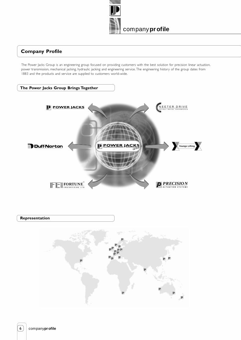
The Power Jacks Group is an engineering group focused on providing customers with the best solution for precision linear actuation,power transmission, mechanical jacking, hydraulic jacking and engineering service. The engineering history of the group dates from1883 and the products and service are supplied to customers world-wide.
The Power Jacks Group Brings Together
Representation

1
engineers reference
sectionnine
Contents
9.1. Useful Formulae for Actuator Calculations 2
9.2. Useful Formulae for Power Transmission Calculations 4
9.3. Conversion Factors 6
9.4. Enclosure Ratings 8
9.5. Metric Nuts and Bolts 9
9.6. Metric Square and Rectangular Parallel Keys 10
9.7. Physical Property Values 11
9.8. Standard SI Prefixes 11
9.9. Limitations of Responsibility 12
9.10. Warranty 12

2
engineers reference
sectionnine
RPM of Worm Shaft * Lifting Screw Lead (mm)
Gear Ratio
9.1. Useful Formulae for Actuator Calculations
9.1.1. Metric Units
9.1.1.1. Lifting Screw Lead
Lifting Screw lead (mm) = Screw Pitch (mm) *Number of Starts on Lifting Screw
Input Torque (Nm) =
Raise Rate (mm/min) =
Raise Rate (mm/min) =
9.1.1.3. Calculation of Actuator Input Torque
Input Power (kW) * 9550
Input Speed (rpm)Input Torque (Nm) =
Load (kN) *Lifting Screw Lead (mm)
2 * π * Actuator Efficiency * Actuator Gear Ratio
9.1.1.4. Calculation of Actuator Input Power
Input Power (kW) =Load (kN) * Raise Rate (mm/min)
60000 * Actuator Efficiency
Input Power (kW) =Load (kN) * Lifting Screw Lead (mm) * Input Speed (rpm)
60000 * Actuator Efficiency * Actuator Gear Ratio
RPM of Worm Shaft
Turns of Worm for 1mm Raise
or alternatively
or alternatively
or alternatively
9.1.1.2. Calculation of the Raise Per Minute with a Given Worm Shaft Speed
When the worm shaft speed is known, the distance the load can be raised per minute can be determined with this formula:

3
engineers reference
sectionnine
or alternatively
RPM of Worm Shaft
Turns of Worm for 1" Raise
RPM of Worm Shaft * Lifting Screw Lead (in)
Gear Ratio
Raise Rate (in/min) =
Raise Rate (in/min) =
9.1.2.3. Calculation of Actuator Input Torque
Input Torque (lbf.in) =Load (lbf) * Lifting Screw Lead (inch)
2 * π * Actuator Efficiency * Actuator Gear Ratio
Input Power (HP) * 63000
Input Speed (rpm)Input Torque (lbf.in) =
or alternatively
9.1.2.4. Calculation of Actuator Input Power
Input Power (HP) =Load (lbf) * Lifting Screw Lead (inch) * Input Speed (rpm)
3.96 x 10⁵ * Actuator Efficiency *Actuator Gear Ratio
or alternatively
Input Power (HP) =Load (lbf) * Raise Rate (inch/min)
3.96 x 10⁵ * Actuator Efficiency
9.1.2. Imperial Units
9.1.2.1. Lifting Screw Lead
Lifting Screw lead (inch) = Screw Pitch (inch) * Number of Starts on Lifting Screw
9.1.2.2. Calculation of the Raise Per Minute with a Given Worm Shaft Speed
When the worm shaft speed is known, the distance the load can be raised per minute can be determined with thisformula:
4
engineers reference
sectionnine
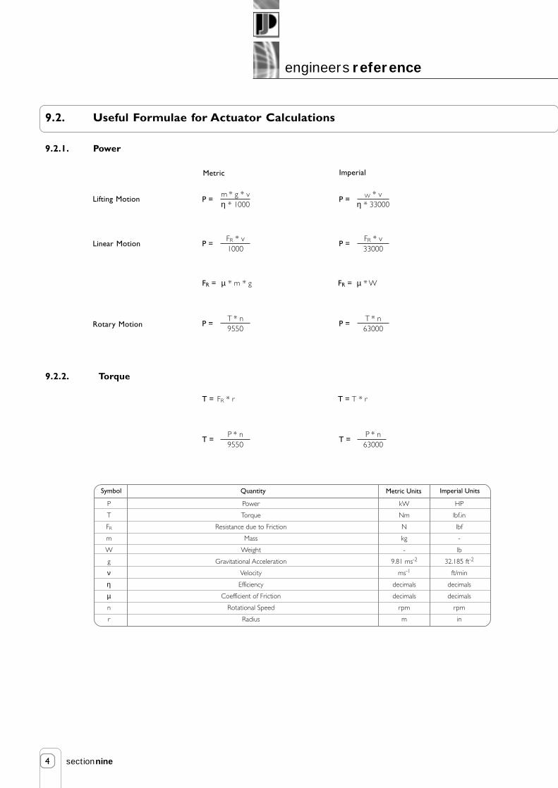
9.2. Useful Formulae for Actuator Calculations
9.2.1. Power
9.2.2. Torque
Lifting Motion
FR = µ * m * g FR = µ * W
T * n9550
P =T * n63000
P =
FR * v1000
P =FR * v33000
P =
m * g * vη * 1000
P = W * vη * 33000
P =
Linear Motion
Rotary Motion
Metric Imperial
T = FR * r T = T * r
P * n9550
T =P * n
63000T =
Symbol
P
T
FR
m
W
g
ν
η
µ
n
r
Power
Torque
Resistance due to Friction
Mass
Weight
Gravitational Acceleration
Velocity
Efficiency
Coefficient of Friction
Rotational Speed
Radius
kW
Nm
N
kg
-
9.81 ms-2
ms-1
decimals
decimals
rpm
m
HP
lbf.in
lbf
-
lb
32.185 ft-2
ft/min
decimals
decimals
rpm
in
Quantity Metric Units Imperial Units

5
engineers reference
sectionnine
9.2.4. Acceleration or Braking Time
9.2.3. Moment of Inertia
1
2J = * m * rod
2
1
32J = * π * ρ * dod
4
J = 0.098 * ρ * I *dod4
1
2WK2 = * W * rod
2
π32
WK2 = * r * I * dod4
WK2 = 0.1 * ρ * I *dod4
1
32J = * π * ρ * I * (dod
4 -did4)
J = 0.098 * ρ * I * (dod4 -did
4)
1
2WK2 = * W * (rod
2 -rid2)
π32
WK2 = * ρ * I * (dod4 -did
4)
WK2 = 0.1 * ρ * I * (dod4 -did
4)
1
2J = * m * (rod
2 -rid2)
Solid Cylinder
Hollow Cylinder
Metric Imperial
J * n
9.55 * Tacctacc =
WK2 * n
308 * Tacctacc =
Symbol
J
WK2
Tacc
m
W
rod
rid
dod
did
I
ρ
tacc
n
Moment of Inertia (metric)
Moment of Inertia (imperial)
Torque due to Acceleration or Braking
Mass
Weight
Outer Radius
Internal Radius
Outer Diameter
Internal Diameter
Length
Density
Time for Acceleration or Braking
Rotational Speed
kgm2
-
Nm
kg
-
m
m
m
m
m
kg/m3
s
rpm
-
lb.ft2
lbf.ft
-
lb
ft
ft
ft
ft
ft
lb/ft3
s
rpm
Quantity Metric Units Imperial Units

6
engineers reference
sectionnine
9.3. Conversion Factors
Force / Weight
1 N
1 kgf
1 kp
1 lbf
Mass
1 kg
1 Tonne
1 lb
1 Ton (Short)
1 Ton
Length
1 m
1 mm
1 inch
1 ft
m
1
0.001
0.0254
0.3048
mm
1000
1
25.4
304.8
inch
39.370
0.03937
1
12
ft
3.2808
3.28 x 10⁻³
0.0833
1
kg
1
1000
0.45355937
907.185
1016.05
Tonne
0.001
1
4.536 x 10⁻⁴
0.907185
1.016
lb
2.2046
2204.6
1
2000
2240
Ton
9.842 x 10⁻⁴
0.9842
4.464 x 10⁻⁴
0.8929
1
Ton (Short)
1.1023 x 10⁻³
1.1023
5 x 10⁻⁴
1
1.120
Speed
1 m/s
1 mm/s
1 ft/s
1 in/s
m/s
1
0.001
0.3048
0.0254
mm/s
1000
1
304.8
25.4
ft/s
3.2808
3.28 x 10⁻³
1
0.0833
in/s
39.37
0.03937
12
1
N
1
9.80665
9.80665
4.44822
kgf
0.1019716
1
1
0.45359237
kp
0.120
1
1
0.4536
lbf
0.224809
2.2046
2.2046
1
Torque / Work
1 Nm
1 kfg.cm
1 lbf.in
1 lbf.ft
Nm
1
9.80665 x 10⁻²
0.1129848
1.35582
kgf.cm
10.19716
1
1.1521
13.825
lbf.in
8.8507
0.8679
1
12
lbf.ft
0.73756
0.07233
0.08333
1

7
engineers reference
sectionnine
9.3. Conversion Factors
Stress / Pressure
1 MPa (N/mm2)
1 N/m2
1 kg/cm2
1 lbf/inch2
1 lbg/ft2
1nertia
kg.m2 (mr2)
1 kpms2
1 lbf.ft2 (WK2)
1 lbf.in2 (WK2)
Power
1 kW
1 Nm/min
1 kgf.m/s
1 hp
1 lbf.ft/min
kW
1
1.667 x 10⁻⁴
9.807 x 10⁻³
0.7457
2.261 x 10⁻⁵
Nm/min
60000
1
588.6
44741
1.3566
kgf.m/s
10.20
1.699 x 10⁻³
1
76.04
2.3056 x 10⁻³
hp
1.34
2.235 x 10⁻⁵
0.01315
1
3.03 x 10⁻⁵
lbf.ft/min
44220
0.7374
433.73
33000
1
kg.m2 (mr2)
1
9.807
0.0421
2.9264 x 10⁻⁴
kpms2
0.10197
1
4.30 x 10⁻³
0.6192
lbf.ft2 (WK2)
23.73
232.6
1
6.944 x 10⁻³
lbf.in2 (WK2)
3417.2
33488
144
1
Temperature
T °F
T °C
(T °C x 1.8) + 32°
(T °F -32) / 1.8
MPa (N/mm2)
1
1 x 10⁻⁶
9.807 x 10⁻²
9.8947 x 10⁻³
4.7879 x 10⁻⁵
kg/cm2
10.2
10.2 x 10⁻⁶
1
0.070307
0.488 x 10⁻³
N/m2
1 x 10⁻⁶
1
9.81 x 10³
6.89 x 10³
47.88026
lbf/inch2
145.039
145 x 10-6
14.2233
1
6.94 x 10⁻³
lbf/ft2
20885.6
20.88 x 10⁻⁶
2.05 x 10
144
1
8
engineers reference
sectionnine
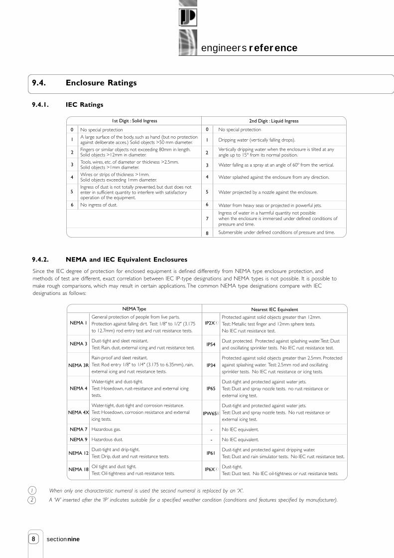
9.4. Enclosure Ratings
9.4.1. IEC Ratings
1 When only one characteristic numeral is used the second numeral is replaced by an ‘X’.
2 A ‘W’ inserted after the ‘IP’ indicates suitable for a specified weather condition (conditions and features specified by manufacturer).
9.4.2. NEMA and IEC Equivalent Enclosures
Since the IEC degree of protection for enclosed equipment is defined differently from NEMA type enclosure protection, andmethods of test are different, exact correlation between IEC IP-type designations and NEMA types is not possible. It is possible tomake rough comparisons, which may result in certain applications. The common NEMA type designations compare with IECdesignations as follows:
No special protection
A large surface of the body, such as hand (but no protectionagainst deliberate acces.) Solid objects >50 mm diameter.
Fingers or similar objects not exceeding 80mm in length.Solid objects >12mm in diameter.
Tools, wires, etc. of diameter or thickness >2.5mm.Solid objects >1mm diameter.
Wires or strips of thickness >1mm.Solid objects exceeding 1mm diameter.
Ingress of dust is not totally prevented, but dust does notenter in sufficient quantity to interfere with satisfactoryoperation of the equipment.
No ingress of dust.
No special protection
Dripping water (vertically falling drops).
Vertically dripping water when the enclosure is tilted at anyangle up to 15º from its normal position.
Water falling as a spray at an angle of 60º from the vertical.
Water splashed against the enclosure from any direction.
Water projected by a nozzle against the enclosure.
Water from heavy seas or projected in powerful jets.
Ingress of water in a harmful quantity not possiblewhen the enclosure is immersed under defined conditions ofpressure and time.
Submersible under defined conditions of pressure and time.
1st Digit : Solid Ingress 2nd Digit : Liquid Ingress
0
1
2
3
4
5
6
0
1
4
5
6
7
8
2
3
IP2XProtected against solid objects greater than 12mm.Test: Metallic test finger and 12mm sphere tests. No IEC rust resistance test.
Dust protected. Protected against splashing water. Test: Dustand oscillating sprinkler tests. No IEC rust resistance test.
Protected against solid objects greater than 2.5mm. Protectedagainst splashing water. Test: 2.5mm rod and oscillatingsprinkler tests. No IEC rust resistance or icing tests.
Dust-tight and protected against water jets.Test: Dust and spray nozzle tests. no rust resistance orexternal icing test.
Dust-tight and protected against water jets.Test: Dust and spray nozzle tests. No rust resistance orexternal icing test.
No IEC equivalent.
No IEC equivalent.
Dust-tight and protected against dripping water.Test: Dust and rain simulator tests. No IEC rust resistance test.
Dust-tight.Test: Dust test. No IEC oil-tightness or rust resistance tests.
NEMA 1General protection of people from live parts. Protection against falling dirt. Test: 1/8" to 1/2" (3.175to 12.7mm) rod entry test and rust resistance tests.
Dust-tight and sleet resistant.Test: Rain, dust, external icing and rust resistance test.
Rain-proof and sleet resitant.Test: Rod entry 1/8" to 1/4" (3.175 to 6.35mm), rain, external icing and rust resistance tests.
Water-tight and dust-tight.Test: Hosedown, rust-resistance and external icing tests.
Water-tight, dust-tight and corrosion resistance.Test: Hosedown, corrosion resistance and external icing tests.
Hazardous gas.
Hazardous dust.
Dust-tight and drip-tight.Test: Drip, dust and rust resistance tests.
Oil tight and dust tight.Test: Oil-tightness and rust-resistance tests.
NEMA Type Nearest IEC Equivalent
NEMA 3
NEMA 3R
NEMA 4
NEMA 4X
NEMA 7
NEMA 9
NEMA 12
NEMA 18
1
IP54
IP34
IP65
IPW65
-
-
IP61
IP6X 1
2
9
engineers reference
sectionnine
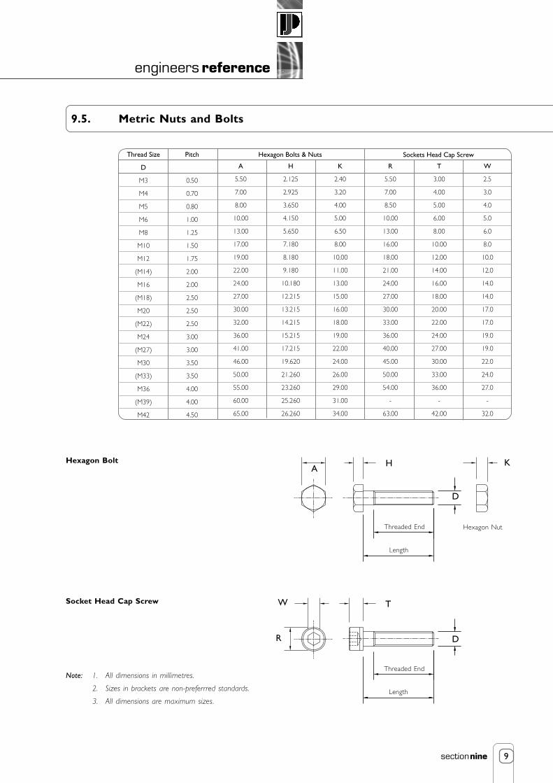
9.5. Metric Nuts and Bolts
A
R
H
D
T
D
W
K
Note: 1. All dimensions in millimetres.
2. Sizes in brackets are non-preferrred standards.
3. All dimensions are maximum sizes.
Hexagon Bolt
Socket Head Cap Screw
Threaded End
Length
Threaded End
Length
Thread Size
D
M3
M4
M5
M6
M8
M10
M12
(M14)
M16
(M18)
M20
(M22)
M24
(M27)
M30
(M33)
M36
(M39)
M42
Pitch
0.50
0.70
0.80
1.00
1.25
1.50
1.75
2.00
2.00
2.50
2.50
2.50
3.00
3.00
3.50
3.50
4.00
4.00
4.50
A
5.50
7.00
8.00
10.00
13.00
17.00
19.00
22.00
24.00
27.00
30.00
32.00
36.00
41.00
46.00
50.00
55.00
60.00
65.00
H
2.125
2.925
3.650
4.150
5.650
7.180
8.180
9.180
10.180
12.215
13.215
14.215
15.215
17.215
19.620
21.260
23.260
25.260
26.260
K
2.40
3.20
4.00
5.00
6.50
8.00
10.00
11.00
13.00
15.00
16.00
18.00
19.00
22.00
24.00
26.00
29.00
31.00
34.00
R
5.50
7.00
8.50
10.00
13.00
16.00
18.00
21.00
24.00
27.00
30.00
33.00
36.00
40.00
45.00
50.00
54.00
-
63.00
T
3.00
4.00
5.00
6.00
8.00
10.00
12.00
14.00
16.00
18.00
20.00
22.00
24.00
27.00
30.00
33.00
36.00
-
42.00
W
2.5
3.0
4.0
5.0
6.0
8.0
10.0
12.0
14.0
14.0
17.0
17.0
19.0
19.0
22.0
24.0
27.0
-
32.0
Hexagon Bolts & Nuts Sockets Head Cap Screw
Hexagon Nut

10
engineers reference
sectionnine
9.6. Metric Square and Rectangular Parallel Keys
Enlarged Detail of Key and Keyways
X
X
B
H
T2T1
D - T1 D + T2
Section X-X
T2
T1
R
H/2H/2
Note: For full range and further informtion refer BS 4235: Pt 1: 1972
SymbolNominalDiameter
D
Key Keyway
B x Hwidth
xthick-ness
Shaft(H9)
Over Incl
Free Normal Shaft, T1
DepthWidth, B
Tolerance for class of fitNom
Radius, R
Hub, T2Close andInterference
Hub(D10)
Shaft(N9)
Hub(Js9)
Shaft andHub(P9)
Nom. Tol. Nom. Tol. Max. Min.
6
8
10
12
17
22
30
38
44
50
58
65
75
85
95
110
130
150
170
8
10
12
17
22
30
38
44
50
58
65
75
85
95
110
130
150
170
200
2
3
4
5
6
8
10
12
14
16
18
20
22
25
28
32
36
40
45
+0.025
0
+0.030
0
+0.036
0
+0.043
0
+0.052
0
+0.062
0
+0.060
+0.020
+0.078
+0.080
+0.095
+0.040
+0.120
+0.050
+0.149
+0.065
+0.180
+0.080
-0.004
-0.029
0
-0.030
0
-0.036
0
-0.043
0
-0.052
0
-0.062
+0.012
-0.012
+0.015
-0.015
+0.018
-0.018
+0.021
-0.021
+0.026
-0.026
+0.031
-0.031
-0.006
-0.031
-0.012
-0.042
-0.015
-0.051
-0.018
-0.061
-0.022
-0.074
-0.022
-0.088
1.2
1.8
2.5
3.0
3.5
4.0
5.0
5.0
5.5
6.0
7.0
7.5
9.0
9.0
10.0
11.0
12.0
13.0
13.0
+0.1
0
+0.2
0
+0.3
0
+0.1
0
+0.2
0
+0.3
0
0.08
0.16
0.25
0.40
0.70
0.16
0.25
0.40
0.60
1.00
1.0
1.4
1.8
2.3
2.8
3.3
3.3
3.3
3.8
4.3
4.4
4.9
5.4
5.4
6.4
7.4
8.4
9.4
10.4
2 x 2
3 x 3
4 x 4
5 x 5
6 x 6
8 x 7
10 x 8
12 x 8
14 x 9
16 x 10
18 x 11
20 x 12
22 x 14
25 x 14
28 x 16
32 x 18
36 x 20
40 x 22
45 x 25
D

11
engineers reference
sectionnine
9.7. Physical Property Values, at 20°C
9.8. Standard SI Prefixes * †
* If possible use multiple and submultiple prefixes in steps of 1000.
† Spaces are used in SI instead of commas to group numbers to avoid confusion with the practise in some Europeancountries of using commas for decimal points.
‡ Not recommened but sometimes encountered.
Material
Density, ρ (kg/m3)
Young's Modulus, E
(GN/m2)
Shear Modulus, G
(GN/m2)
Bulk Modulus, K
(GN/m2)
Poisson's Ratio, ν
Coefficient of Thermal
Expansion x 10-6/K
Specific Heat J/kg K
Carbon Steel
7860
207
79.3
172
0.292
12
460
Brass 65/35
8450
105
38
115
0.35
19
420
Copper
8910
119
44.7
130
0.326
17
420
Stainless Steel
7750
190
73.1
178
0.305
14
460
Aluminium Alloys
2710
710
26.2
57.5
0.334
22
920
Name
exa
peta
tera
giga
mega
kilo
hecto
deca
deci
centi
milli
micro
nano
pico
femto
atto
Symbol
E
P
T
G
M
k
h
da
d
c
m
µ
n
p
f
a
Factor
1 000 000 000 000 000 000 = 1018
1 000 000 000 000 000 = 1015
1 000 000 000 000 = 1012
1 000 000 000 = 109
1 000 000 = 106
1 000 = 103
100 = 102
10 = 101
0.1 = 10-1
0.01 = 10-2
0.001 = 10-3
0.000 001 = 10-6
0.000 000 001 = 10-9
0.000 000 000 001 = 10-12
0.000 000 000 000 001 = 10-15
0.000 000 000 000 000 001 = 10-18
‡
‡
‡
‡
Note: Values given are representative. Exact values may vary with composition and processing, sometimes greatly.

12
engineers reference
sectionnine
9.9. Limitation of Responsibility
The ratings given in this catalogue were compiled using standard engineering procedures. The ratings are designed to guide thecustomer in the selection of a unit. We do not guarantee the ratings in specific applications. Prototype testing of every application isrecommended before production. Our engineering facilities are available for consultation at all times. Please ask us for assistance withlinear motion and drive application problems. This catalogue is designed to assist in the selection of a suitable linear motion or powertransmission product for economical, long and trouble free service.
Due to Power Jacks policy of continuous improvement designs may be subject to change without notice. Please ask for certifieddrawings.
9.10. Warranty
Subject to the condition stated herein. Power Jacks will repair or replace, without charge, any parts proven to Power Jacks satisfactionto have been defective in material or workmanship. Claims must be made within one year after date of shipment. Power Jacks will notrepair or replace any parts that become inoperative because of improper maintenance, eccentric loading, overloading, chemical orabrasive action, excessive heat, or other abuse. Equipment and accessories not of Power Jacks manufacture are warranted only to theextent that they are warranted by the manufacturer, and only if the claimed defect arose during normal use, application and service.Equipment, which has been altered or modified by anyone without Power Jacks authorisation, is not warranted by Power Jacks. EXCEPTAS STATED HEREIN, POWER JACKS MAKES NO OTHER WARRANTIES, EXPRESS OR IMPLIED INCLUDING WARRANTIES OFMERCHANTABILITY AND FITNESS FOR A PARTICULAR PURPOSE.
WARNING: The equipment shown in this catalogue is intended for industrial use only and should not be used to lift, support, orotherwise transport people unless you have a written statement from Power Jacks Limited which authorises the specific unit as used inyour application suitable for moving people.
© Power Jacks Limited 1987, Aberdeenshire, Scotland, United Kingdom.
© Neeter Drive is a trading name of Power Jacks Limited.
© Precision Actuation Systems is a Power Jacks Company.
© Duff-Norton Company 1986, Charlotte, North Carolina, USA.
© Youngs Lifting is a trading name of Power Jacks Limited.
© Fortune Engineering is a trading name of Power Jacks Limited.
© Rolaram® is a trademark of Power Jacks Limited.
All rights reserved by Power Jacks Limited. May not be copied in whole or in part.