S800 I/O Product Guide - ABB Ltd · PDF fileS800 I/O Product Guide System Version 5.1. S800...
184
Power and productivity for a better world TM S800 I/O Product Guide System Version 5.1
Transcript of S800 I/O Product Guide - ABB Ltd · PDF fileS800 I/O Product Guide System Version 5.1. S800...
Power and productivity
for a better worldTM
S800 I/OProduct Guide
System Version 5.1

S800 I/O
Product Guide
System Version 5.1

NOTICEThis document contains information about one or more ABB products and may include adescription of or a reference to one or more standards that may be generally relevant tothe ABB products. The presence of any such description of a standard or reference to astandard is not a representation that all of the ABB products referenced in this documentsupport all of the features of the described or referenced standard. In order to determinethe specific features supported by a particular ABB product, the reader should consult theproduct specifications for the particular ABB product.
ABB may have one or more patents or pending patent applications protecting the intel-lectual property in the ABB products described in this document.
The information in this document is subject to change without notice and should not beconstrued as a commitment by ABB. ABB assumes no responsibility for any errors thatmay appear in this document.
In no event shall ABB be liable for direct, indirect, special, incidental or consequentialdamages of any nature or kind arising from the use of this document, nor shall ABB beliable for incidental or consequential damages arising from use of any software or hard-ware described in this document.
This document and parts thereof must not be reproduced or copied without written per-mission from ABB, and the contents thereof must not be imparted to a third party nor usedfor any unauthorized purpose.
The software or hardware described in this document is furnished under a license andmay be used, copied, or disclosed only in accordance with the terms of such license. Thisproduct meets the requirements specified in EMC Directive 2004/108/EEC and in LowVoltage Directive 2006/95/EEC.
TRADEMARKSAll rights to copyrights, registered trademarks, and trademarks reside with their respec-tive owners.
Copyright © 2003-2013 by ABB. All rights reserved.
Release: April 2013Document number: 3BSE015969-510 A

3BSE015969-510 A 5
Table of Contents
About This Product GuideGeneral ..............................................................................................................................9
Product Guide Conventions .............................................................................................10
Warning, Caution, Information, and Tip Icons................................................................10
Terminology.....................................................................................................................11
Released User Manuals and Release Notes.....................................................................13
New in this Release .........................................................................................................13
Section 1 - Key BenefitsProduct Benefits ..............................................................................................................18
Features............................................................................................................................19
Section 2 - Product DescriptionIntroduction .....................................................................................................................21
Product Overview ............................................................................................................24
S800 I/O Station...................................................................................................26
Base Cluster .........................................................................................................26
I/O Cluster ............................................................................................................26
I/O Modules .........................................................................................................26
Functional Description ....................................................................................................28
Product Configuration Examples .........................................................................28
Communication ....................................................................................................30
Fieldbus Communication Interface ......................................................................35
Module Termination.............................................................................................37
ModuleBus Items .................................................................................................40
I/O Modules .........................................................................................................43
Table of Contents
6 3BSE015969-510 A
Drives Integration ................................................................................................ 54
Support for connections to instruments in Hazardous Areas............................... 57
Support for Externally Connected Accessories ................................................... 58
Support for HART Communication..................................................................... 60
Support for Safety System Requirements ............................................................ 61
Redundancy Functionality ................................................................................... 61
Software Components ..................................................................................................... 62
Hardware Components.................................................................................................... 63
I/O Modules ......................................................................................................... 63
Module Termination Unit .................................................................................... 65
Fieldbus Communication Interface...................................................................... 72
ModuleBus........................................................................................................... 79
Power Supplies..................................................................................................... 93
Mounting Equipment ......................................................................................... 101
G3 compliant modules ....................................................................................... 105
I/O Station Configurations................................................................................. 105
Mounting .......................................................................................................... 109
Section 3 - Technical Data and PerformanceDirectives....................................................................................................................... 117
EMC Directive ................................................................................................... 117
Low Voltage Directive ....................................................................................... 117
ATEX directive .................................................................................................. 117
Standards and Approvals............................................................................................... 118
Electrical Safety ................................................................................................. 118
Hazardous Classified Locations......................................................................... 118
CE-marking........................................................................................................ 119
G3 Compliant..................................................................................................... 119
Transport and Storage Conditions................................................................................. 119
Climatic Operating Conditions ..................................................................................... 121
Mechanical Operating Conditions................................................................................. 121
EMC ........................................................................................................................... 122
Overvoltage Categories...................................................................................... 124
Table of Contents
3BSE015969-510 A 7
3BSE015969-510 A 7
Equipment Class and Insulation Voltages .....................................................................124
Equipment Class.................................................................................................124
Insulation Voltage...............................................................................................124
Insulation Test Voltage .......................................................................................125
Capacity and Performance.............................................................................................126
Advant Fieldbus 100 Load .................................................................................126
PROFIBUS CI801..............................................................................................130
PROFIBUS CI840..............................................................................................136
S800 I/O Station Data Scanning ........................................................................143
Calculation of Maximum Distance of an Optical ModuleBus Configuration ...148
Power Supply and Cooling Requirements .........................................................152
Supported I/O Modules and Drives via Advant Fieldbus 100.......................................164
Supported I/O Modules and Drives via PROFIBUS and CI801....................................164
Supported I/O Modules and Drives via PROFIBUS and CI840....................................165
Intrinsic Safety Parameters ............................................................................................166
Certifications .................................................................................................................169
Section 4 - OrderingGeneral ..........................................................................................................................177
Product and Price List Structure ........................................................................177
INDEX

Table of Contents
8 3BSE015969-510 A
3BSE015969-510 A 9
About This Product Guide
General
This Product Guide is primarily intended for sales representatives within ABB. The Product Guide is distributed to internal ABB customers and to important external customers, as a complement to existing product information.
This Product Guide describes the S800 I/O system, presenting information in terms of what can be installed and configured as well as operational possibilities.
This Product Guide does not describe the different controller connect products. For more details, see separate product guides.
The product guide is intended as an introduction to S800 I/O system, as well as a reference when discussing technical solutions with customers.
The guide provides:
• Information on S800 I/O system key benefits, both on product and functional levels.
• An overview of functions offered by S800 I/O system.
Any security measures described in this Product Guide, for example, for user access, password security, network security, firewalls, virus protection, etc., represent possible steps that a user of an 800xA System may want to consider based on a risk assessment for a particular application and installation. This risk assessment, as well as the proper implementation, configuration, installation, operation, administration, and maintenance of all relevant security related equipment, software, and procedures, are the responsibility of the user of the 800xA System.
This Product Guide does not contain last-minute product information and updates which might affect functionality and/or performance. For information on late changes and restrictions, refer the Release Notes.
Product Guide Conventions About This Product Guide
10 3BSE015969-510 A
• Technical and Performance data for S800 I/O system.
• Instructions on how to order, with reference to system configurations.
Product Guide ConventionsMicrosoft Windows conventions are normally used for the standard presentation of material when entering text, key sequences, prompts, messages, menu items, screen elements, etc.
Warning, Caution, Information, and Tip IconsThis Product Guide includes Warning, Caution, and Information where appropriate to point out safety related or other important information. It also includes Tip to point out useful hints to the reader. The corresponding symbols should be interpreted as follows:
Although Warning hazards are related to personal injury, and Caution hazards are associated with equipment or property damage, it should be understood that operation of damaged equipment could, under certain operational conditions, result in degraded process performance leading to personal injury or death. Therefore, fully comply with all Warning and Caution notices.
Electrical warning icon indicates the presence of a hazard that could result in electrical shock.
Warning icon indicates the presence of a hazard that could result in personal injury.
Caution icon indicates important information or warning related to the concept discussed in the text. It might indicate the presence of a hazard that could result in corruption of software or damage to equipment/property.
Information icon alerts the reader to pertinent facts and conditions.
Tip icon indicates advice on, for example, how to design your project or how to use a certain function

About This Product Guide Terminology
3BSE015969-510 A 11
TerminologyA complete and comprehensive list of terms is included in System 800xA System Guide Functional Description (3BSE038018*). The listing includes terms and definitions that apply to the 800xA System where the usage is different from commonly accepted industry standard definitions and definitions given in standard dictionaries such as Webster’s Dictionary of Computer Terms. Terms that uniquely apply to this Product Guide are listed in the following table.
Term Description
AF 100 Advant Fieldbus 100 is the communications bus between the I/O stations and the Advant Controllers. (FCI to CI52x)
DTM Device Type Manager is a standardized software for configuration, diagnostics, HART data communication based on the FDT standard.
FCI The Fieldbus Communication Interface (FCI) device contains the interface to the fieldbus (e.g. AF 100), ModuleBus interface and power regulators. The FCI module can manage 24 I/O devices (up to 12 directly and to the others in 1 to 7 I/O clusters).
Base cluster Consists of single or red. FCIs plus I/O modules connected directly to the FCI.
G3 compliant The module withstand more severe environmental conditions according to ISA-S71.04.
HART Highway Addressable Remote Terminal is a digital communication protocol developed for applications in industrial process metrology.
I/O cluster An extension of the I/O station’s ModuleBus connected to the FCI by fiber optic connections. Up to 12 I/O devices per cluster.
I/O device A complete I/O device consists of one MTU and one I/O module.
I/O module Is an active, electronic and signal conditioning unit. Can be a part of an I/O device or a S800L I/O module.

Terminology About This Product Guide
12 3BSE015969-510 A
I/O station An I/O station consists of one or two FCI(s), 1-7 I/O clusters and up to 24 I/O devices.
ModuleBus Is an incremental, electrical or optical, bus for interconnection of I/O devices.
(ModuleBus) Extension cable
Is used when extending the electrical ModuleBus (within the max. 2 meters).
MTU The Module Termination Unit is a passive base unit containing process terminals and a part of the ModuleBus.
OSP Outputs Set as Predetermined. A user configurable action on an output module when communications is lost to the FCI or Controller.
PROFIBUS-DP PROFIBUS-DP is a fieldbus standard.
PROFIBUS-DPV1 PROFIBUS-DPV1 is a fieldbus standard.
RTD Resistance Temperature Detector.
SOE Sequence of events. Time stamping of status changes for digital inputs.
TC Thermocouple
I.S. Intrinsic Safety is a protection technique to prevent explosion in hazardous areas of a process plant.
SIL Safety Integration Level
HCIR Hot Configuration in Run
CI810 Stands for CI810, CI810V1, CI810V2, CI810A and CI810B
CI840 Stands for CI840 and CI840A
TB840 Stands for TB840 and TB840A
Term Description
About This Product Guide Released User Manuals and Release Notes
3BSE015969-510 A 13
Released User Manuals and Release NotesA complete list of all User Manuals and Release Notes applicable to System 800xA is provided in System 800xA Released User Manuals and Release Notes (3BUA000263*).
System 800xA Released User Manuals and Release Notes (3BUA000263*) is updated each time a document is updated or a new document is released. It is in pdf format and is provided in the following ways:
• Included on the documentation media provided with the system and published to ABB SolutionsBank when released as part of a major or minor release, Service Pack, Feature Pack, or System Revision.
• Published to ABB SolutionsBank when a User Manual or Release Note is updated in between any of the release cycles listed in the first bullet.
New in this ReleaseNew functions in the S800 I/O system:
• Support for the following modules, termination units, and modems:
– Termination unit TU818, TU819, TU851, TU852, TU854
– Digital I/O module DI818 and DI828
– Digital I/O module DO818 and DO828
A product bulletin is published each time System 800xA Released User Manuals and Release Notes (3BUA000263*) is updated and published to ABB SolutionsBank.
Always check which S800 I/O feature support is included in the controller that the I/O is connected to.

New in this Release About This Product Guide
14 3BSE015969-510 A

3BSE015969-510 A 15
Safety Summary
Electrostatic Sensitive DeviceDevices labeled with this symbol require special handling precautions as described in the installation section.
GENERAL WARNINGS
Equipment EnvironmentAll components, whether in transportation, operation or storage, must be in a non-corrosive environment.
Electrical Shock Hazard During MaintenanceDisconnect power or take precautions to insure that contact with ener-gized parts is avoided when servicing.
SPECIFICWARNINGS
Page 112: In I.S. applications, modules with I.S. Interfaces MUST be mounted right most of the I/O station or as a separate group.
The installation must be performed by qualified personnel. It must comply with the relevant national/international standards (e.g. IEC 79-14, CEI 64-2, BS 5345 Pt. 4, DIN VDE 165) and in-line with the established instal-lation rules and recommended practice (e.g. CEI 64-8, ANSI/ISA RP-12.6). The conformity of hazardous area field devices with the related system documentation must always be checked.
When using modules with I.S. Interfaces in non I.S.applications, the I.S. modules can be placed in any position following the same rules as non I.S. modules.
SPECIFIC CAUTIONS
Page 126: The calculated load of Advant Fieldbus 100 must be equal to or less than 70%.
Page 128: The calculated load of Advant Fieldbus 100 must be equal to or less than 50%. NOTE! 1 ms cycle time is not allowed.
Page 129: The calculated load of Advant Fieldbus 100 must be equal to or less than 50%. NOTE! 1 ms cycle time is not allowed.

16 3BSE015969-510 A
Safety Summary
3BSE015969-510 A 17
Section 1 Key Benefits
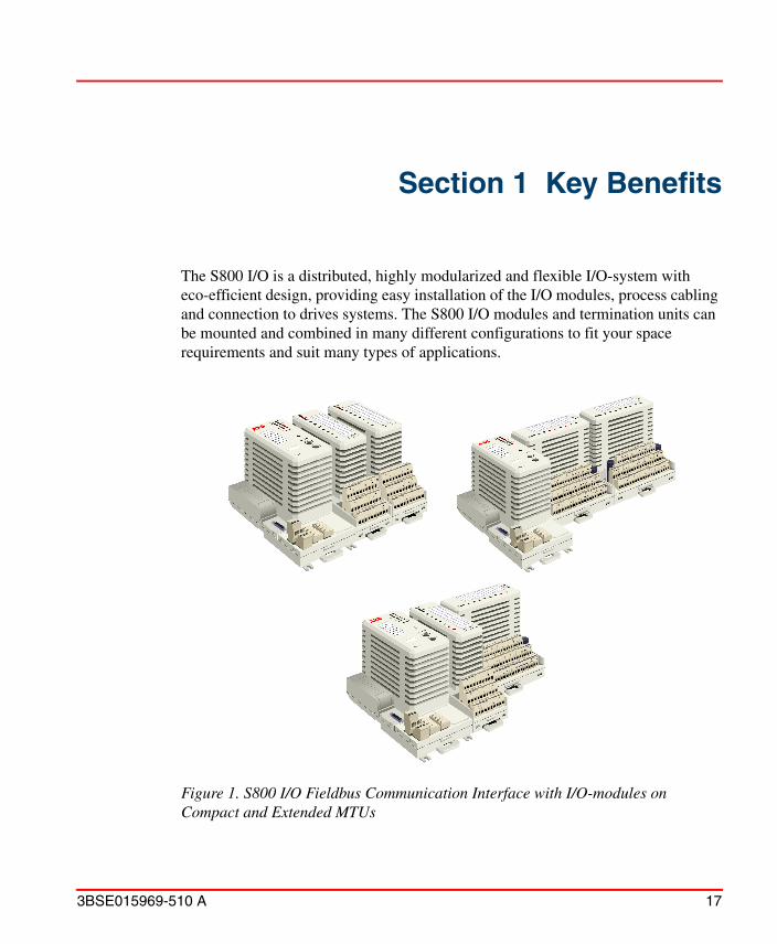
The S800 I/O is a distributed, highly modularized and flexible I/O-system with eco-efficient design, providing easy installation of the I/O modules, process cabling and connection to drives systems. The S800 I/O modules and termination units can be mounted and combined in many different configurations to fit your space requirements and suit many types of applications.
Figure 1. S800 I/O Fieldbus Communication Interface with I/O-modules on Compact and Extended MTUs
Product Benefits Section 1 Key Benefits
18 3BSE015969-510 A
Product BenefitsSome of the benefits of the S800 I/O system are:
• Flexibility, permitting a virtually infinite number of installation arrangements for any application:
– small to large
– easy mounting on a DIN-rail
• Modularity, permitting step-by-step expansion
• Cost-effectiveness, with respect to hardware, cabling, installation and maintenance
• Reliability and auto-diagnostics
• Saves panel costs
• Reduces downtime
• Easy to configure
• Redundancy can be introduced on all levels
Section 1 Key Benefits Features
3BSE015969-510 A 19
FeaturesThe major features of the S800 I/O system are:
• Communicates over PROFIBUS-DP/DPV1 or Advant Fieldbus 100.
• Quick fault-finding with the help of LEDs of each module and channel.
• An extensive scope of Digital input/output modules and Analog input/output modules.
• Digital input/output modules and Analog input/output modules with Intrinsic Safety interfaces.
• Mounted on standard DIN-rails type NS 35/75 according to EN 50022.
• Support of dual redundancy in power supply, fieldbus connection and I/O channel.
• Support of fieldbus media supervision, bumpless change-over and failure reporting.
• All outputs can be individually set to freeze or to take on predefined values.
• Easy connection to drives systems, minimizing communication delays and cost.
• All modules have plastic injection molded enclosures which provide safety protection degree IP20 according to IEC 529.The plastic used is halogen free.
• I/O modules are protected by a mechanical keying arrangement from destruction such as if an attempt is made to insert a module type in a position with a different key code rather than the factory set code of the I/O module. Terminal units have keys which are set to key code of its I/O module’s key code.(S800L I/O modules do not use Termination Units).
• An electrical ID is checked at start-up, if this does not match the configured type, the I/O module is not taken into operation.
• Hot swap of S800 I/O modules (except S800L modules) allowing replacement of faulty modules without disconnecting field power or system power to the I/O station.
Features Section 1 Key Benefits
20 3BSE015969-510 A
• HART pass-through communication.
• I/O modules allow for 55oC ambient temperature except for vertical mounted Compact MTU with I/O modules and vertically mounted S800L allow for 40oC ambient temperature.
• Support of connection to external Intrinsic Safety Barriers.
• High integrity I/O modules, IEC 61508 SIL3 certified.
• Hot Configuration In Run via Profibus.
• Coated modules.
• Galvanic isolation between process and system. Channel based galvanic isolation is also available.
• SOE support by time stamped events with resolution down to 0.4 ms. Available for 24/48/125 V d.c. digital inputs.
• Long distance distribution in star configuration.
• G3 compliant.

3BSE015969-510 A 21
Section 2 Product Description
IntroductionFigure 2 shows the basic construction of I/O stations without any redundancy. To increase the up-time, a number of component can be set up with redundancy:
• Power Supply
• I/O Module
• Fieldbus Communication Interface (FCI)
• Fieldbus
• ModuleBus

Introduction Section 2 Product Description
22 3BSE015969-510 A
Figure 2. I/O Station Overview
Controller
Fieldbus
Optical
Optical ModuleBus Modem
I/O ModuleFCI
ModuleBus
ModuleBus Optical Port
Base Cluster
I/O Cluster
I/O Station
Electrical ModuleBus
I/O Cluster
Base Cluster

Section 2 Product Description Introduction
3BSE015969-510 A 23
An example of a system using redundancy for all these components is shown in Figure 3.
Figure 3. I/O Station Overview with Maximum Redundancy and Additional Single I/O Modules
Redundant
ModuleBus Redundant electrical ModuleBusOptical Port
Optical
Optical ModuleBus Modem
ModuleBus
I/O Cluster, single I/O
I/O Cluster, single I/O
Controller
Redundant FCI
RedundantI/O module
RedundantFieldbus

Product Overview Section 2 Product Description
24 3BSE015969-510 A
It is not necessary to implement redundancy on all components, but there are some dependencies:
• Redundant FCI requires:– redundant fieldbus
• Redundant I/O Module (only in base cluster) requires:– double electrical ModuleBus– redundant FCI– redundant fieldbus
Product OverviewS800 I/O provides distributed I/O on PROFIBUS and Advant Fieldbus 100 (AF100). S800 I/O is also used as a communication link to some of ABB’s Drives.
With the network definition PROFIBUS, it means both the versions; PROFIBUS-DP and PROFIBUS-DPV1.
An I/O station can be configured over the Fieldbus. Typical parameters are signal range, filter time, etc.
The status of the modules are indicated by LEDs and also accessible over the fieldbus. Analog values are scaled 0-100% of the signal range. AI/AO modules are scanned every 4th I/O scan cycle. RTD/TC every 10th cycle.
Values are transferred cyclically on the fieldbus limited by the fieldbus and the fieldbus master. The Fieldbus Communication Interface is scanning the I/O modules cyclically. The cycle time, 4-108 ms, is dependent on type and number of modules.

Section 2 Product Description Product Overview
3BSE015969-510 A 25
In general, all S800 I/O units are G3 compliant. G3 compliant units withstand more severe environmental conditions according to ISA-S71.04. The following S800 I/O units are G2 compliant - SD831, SD832, SD833, SD834, SS832, and TB811. G3 compliant versions of SD822 and SS822 are available, refer to SD822Z and SS822Z.
The modules are marked with a bar code that shows serial number, article ID and product revision number. A separate bar code strip is enclosed for optional placing on the module. The bar code is of type Bar-code 128.
Figure 4. S800 I/O Station
S800 I/O Station Section 2 Product Description
26 3BSE015969-510 A
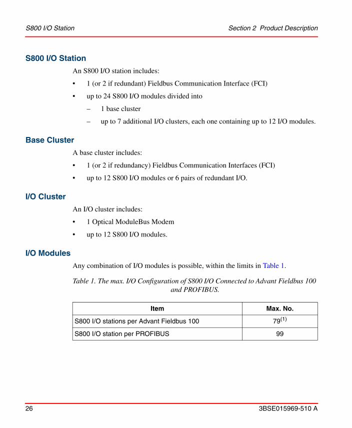
S800 I/O Station
An S800 I/O station includes:
• 1 (or 2 if redundant) Fieldbus Communication Interface (FCI)
• up to 24 S800 I/O modules divided into
– 1 base cluster
– up to 7 additional I/O clusters, each one containing up to 12 I/O modules.
Base Cluster
A base cluster includes:
• 1 (or 2 if redundancy) Fieldbus Communication Interfaces (FCI)
• up to 12 S800 I/O modules or 6 pairs of redundant I/O.
I/O Cluster
An I/O cluster includes:
• 1 Optical ModuleBus Modem
• up to 12 S800 I/O modules.
I/O Modules
Any combination of I/O modules is possible, within the limits in Table 1.
Table 1. The max. I/O Configuration of S800 I/O Connected to Advant Fieldbus 100 and PROFIBUS.
Item Max. No.
S800 I/O stations per Advant Fieldbus 100 79(1)
S800 I/O station per PROFIBUS 99
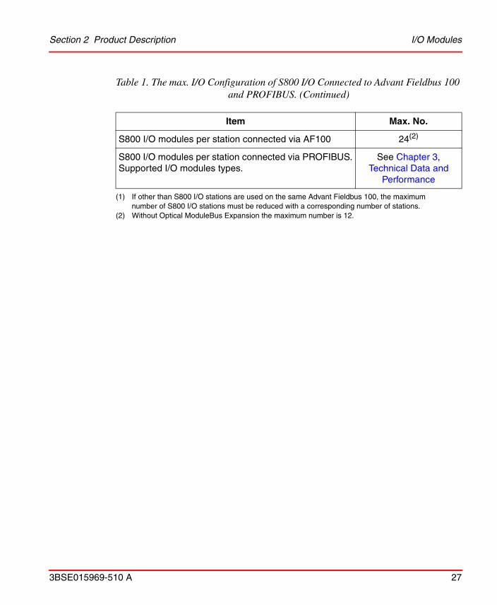
Section 2 Product Description I/O Modules
3BSE015969-510 A 27
S800 I/O modules per station connected via AF100 24(2)
S800 I/O modules per station connected via PROFIBUS.Supported I/O modules types.
See Chapter 3, Technical Data and
Performance
(1) If other than S800 I/O stations are used on the same Advant Fieldbus 100, the maximum number of S800 I/O stations must be reduced with a corresponding number of stations.
(2) Without Optical ModuleBus Expansion the maximum number is 12.
Table 1. The max. I/O Configuration of S800 I/O Connected to Advant Fieldbus 100 and PROFIBUS. (Continued)
Item Max. No.
Functional Description Section 2 Product Description
28 3BSE015969-510 A
Functional Description
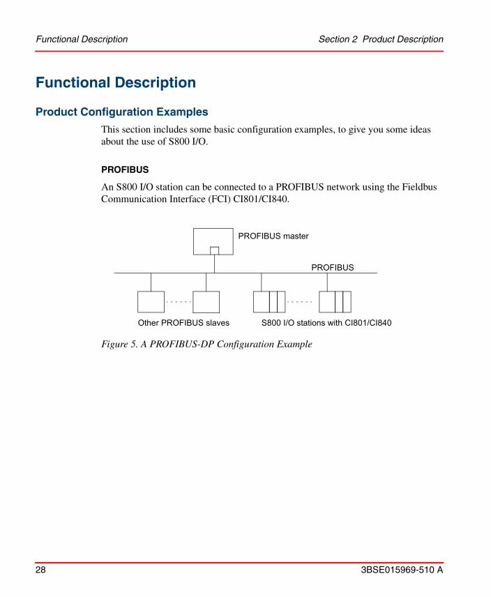
Product Configuration Examples
This section includes some basic configuration examples, to give you some ideas about the use of S800 I/O.
PROFIBUS
An S800 I/O station can be connected to a PROFIBUS network using the Fieldbus Communication Interface (FCI) CI801/CI840.
Figure 5. A PROFIBUS-DP Configuration Example
PROFIBUS master
Other PROFIBUS slaves S800 I/O stations with CI801/CI840
PROFIBUS

Section 2 Product Description Product Configuration Examples
3BSE015969-510 A 29
PROFIBUS with redundancy
Redundancy on PROFIBUS includes redundant cable, redundant Fieldbus Communication Interface CI840 and redundant I/O modules.
Advant Fieldbus 100 with or without media redundancy
Media redundancy on Advant Fieldbus 100 includes redundant cable, redundant modems and the CI810 FCI.
Figure 6. A PROFIBUS-DPV1 Configuration with Redundancy Example
Figure 7. An AF100 Configuration with/without Media Redundancy Example
Other PROFIBUS slaves S800 I/O station with redundant CI840
PROFIBUS masterPROFIBUS master
Other AF100 slaves S800 I/O stations with CI810
AF100
AF100 masterwith
media redundancy
Communication Section 2 Product Description
30 3BSE015969-510 A
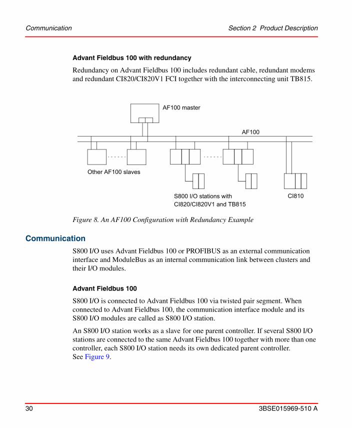
Advant Fieldbus 100 with redundancy
Redundancy on Advant Fieldbus 100 includes redundant cable, redundant modems and redundant CI820/CI820V1 FCI together with the interconnecting unit TB815.
Communication
S800 I/O uses Advant Fieldbus 100 or PROFIBUS as an external communication interface and ModuleBus as an internal communication link between clusters and their I/O modules.
Advant Fieldbus 100
S800 I/O is connected to Advant Fieldbus 100 via twisted pair segment. When connected to Advant Fieldbus 100, the communication interface module and its S800 I/O modules are called as S800 I/O station.
An S800 I/O station works as a slave for one parent controller. If several S800 I/O stations are connected to the same Advant Fieldbus 100 together with more than one controller, each S800 I/O station needs its own dedicated parent controller. See Figure 9.
Figure 8. An AF100 Configuration with Redundancy Example
Other AF100 slaves
AF100
AF100 master
S800 I/O stations withCI820/CI820V1 and TB815
CI810

Section 2 Product Description Communication
3BSE015969-510 A 31
PROFIBUS
S800 I/O and a communication interface module can be directly connected to PROFIBUS-DP or PROFIBUS-DPV1 network.
When connected to PROFIBUS, the communication interface module and its S800 I/O modules are called a S800 I/O station.
An S800 I/O station works as a slave on PROFIBUS.
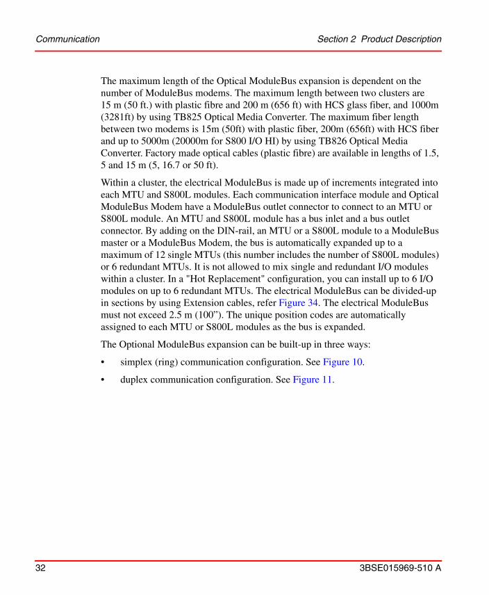
ModuleBus
A Fieldbus Communication Interface module communicates with its S800 I/O modules over the ModuleBus. It communicates internally in the base cluster and externally with other additional clusters within the same S800 I/O station by using Optical ModuleBus Modems TB820, TB840 or TB840A. The Optical ModuleBus Modems are connected via optical cables to a ModuleBus Optical port module on the communication interface module.
Figure 9. Connection to Advant Fieldbus 100
AC4XX IBM PCTool
AC110S800I/O
#1
S800I/O#4
S800I/O#3
S800I/O#2
S800I/O#5
AF100 #1
AF100 #2
S800 I/Owhich workswith AC4XXas ParentController
S800 I/Owhich workswith AC110as ParentController
Communication Section 2 Product Description
32 3BSE015969-510 A
The maximum length of the Optical ModuleBus expansion is dependent on the number of ModuleBus modems. The maximum length between two clusters are 15 m (50 ft.) with plastic fibre and 200 m (656 ft) with HCS glass fiber, and 1000m (3281ft) by using TB825 Optical Media Converter. The maximum fiber length between two modems is 15m (50ft) with plastic fiber, 200m (656ft) with HCS fiber and up to 5000m (20000m for S800 I/O HI) by using TB826 Optical Media Converter. Factory made optical cables (plastic fibre) are available in lengths of 1.5, 5 and 15 m (5, 16.7 or 50 ft).
Within a cluster, the electrical ModuleBus is made up of increments integrated into each MTU and S800L modules. Each communication interface module and Optical ModuleBus Modem have a ModuleBus outlet connector to connect to an MTU or S800L module. An MTU and S800L module has a bus inlet and a bus outlet connector. By adding on the DIN-rail, an MTU or a S800L module to a ModuleBus master or a ModuleBus Modem, the bus is automatically expanded up to a maximum of 12 single MTUs (this number includes the number of S800L modules) or 6 redundant MTUs. It is not allowed to mix single and redundant I/O modules within a cluster. In a "Hot Replacement" configuration, you can install up to 6 I/O modules on up to 6 redundant MTUs. The electrical ModuleBus can be divided-up in sections by using Extension cables, refer Figure 34. The electrical ModuleBus must not exceed 2.5 m (100”). The unique position codes are automatically assigned to each MTU or S800L modules as the bus is expanded.
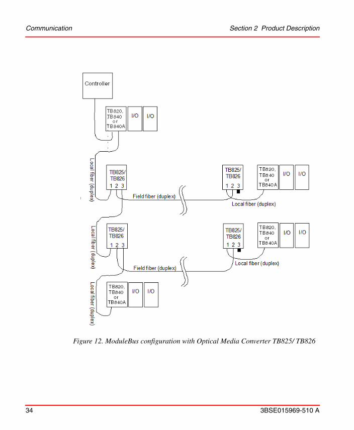
The Optional ModuleBus expansion can be built-up in three ways:
• simplex (ring) communication configuration. See Figure 10.
• duplex communication configuration. See Figure 11.

Section 2 Product Description Communication
3BSE015969-510 A 33
• star configuration with the Optical Media Converter. See Figure 12.
• Simplex provides a one-way ring connection from the FCI to the modem, to the second modem, etc., and back from the last modem to the FCI.
• Duplex provides a two-way connection, and is normally the best communication design.
• Duplex allows additional modems to be added down-stream on-line.
• A cable break or loss of a modem will only affect I/O clusters down-stream of the failure.
Figure 10. Optical ModuleBus and I/O Clusters, Simplex Communication
Figure 11. Optical ModuleBus and I/O Clusters, Duplex Communication
Cluster 1TB820
Cluster 2TB820
Cluster 3TB820
Cluster 7TB820
Rx Rx Rx Rx
Tx
TxTxTx
Rx Tx
I/O Station Maximum length of any cable is:15 m (49 ft.) for plastic fiber200 m (667 ft.) for HCS glass fiber
Cluster 1TB820
Cluster 2TB820
Cluster 3TB820
Cluster 7TB820
Rx Rx Rx Rx
Tx
TxTxTx
Rx Tx
I/O Station Maximum length of any cable is:15 m (49 ft.) for plastic fiber200 m (667 ft.) for HCS glass fiber
Tx Tx TxRx Rx Rx
Communication Section 2 Product Description
34 3BSE015969-510 A
Figure 12. ModuleBus configuration with Optical Media Converter TB825/ TB826

Section 2 Product Description Fieldbus Communication Interface
3BSE015969-510 A 35
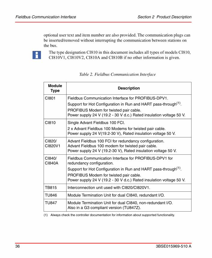
Fieldbus Communication Interface
A Fieldbus Communication Interface module is used as communication interface to connect S800 I/O modules to the fieldbus.
There are five different FCI modules:
• CI801 – for PROFIBUS-DPV1
• CI810 – for Advant Fieldbus 100, with or without media redundancy
• CI820/CI820V1 – for Advant Fieldbus 100 fully redundant communication
• CI840 – for PROFIBUS-DPV1 fully redundant communication
They all have an isolated input for 24 V d.c. power (19.2 - 30 V). The power source can be the SD831/ SD832/ SD833/ SD834 power supplies, battery, or other IEC664 Installation Category II power sources. Power status inputs, 2 x 24 V, to monitor 1:1 redundant mains are also provided.
CI801 has a 9 pin D-sub connector and modems for PROFIBUS-DPV1 and a connection for the Optical ModuleBus via TB806/TB842.
CI810 has two connectors and modems for a media redundant Advant Fieldbus 100 twisted pair cables and a connection for the Optical ModuleBus.
CI820/CI820V1, together with the interconnection unit TB815, is used when a fully redundant configuration is required. CI820/CI820V1 comprises the Advant Fieldbus 100 twisted pair connection and TB815 the Optical ModuleBus connection.
CI840, together with termination unit TU846/TU847, is used when a fully redundant configuration is required. CI840 is mounted on TU846/TU847 and has a connector for power supply and two 9 pin D-sub connectors for PROFIBUS-DPV1 connection. TU846/TU847 has two service ports and two address switches. CI840 also has a connection for the Optical ModuleBus via TB806/TB842 or TB846/TB842.
CI801 and CI840 supports Hot Configuration in Run (HCIR) and HART pass-through. HCIR makes it possible to change the I/O station configuration without stopping the I/O station execution.
The front plate of the communication modules provides LEDs for diagnostic and status indications. Two rotary switches are provided for setting of the I/O station address. No other addresses are required to be set within the I/O station. Labels for
Fieldbus Communication Interface Section 2 Product Description
36 3BSE015969-510 A
optional user text and item number are also provided. The communication plugs can be inserted/removed without interrupting the communication between stations on the bus.
The type designation CI810 in this document includes all types of models CI810, CI810V1, CI810V2, CI810A and CI810B if no other information is given.
Table 2. Fieldbus Communication Interface
Module Type
Description
CI801 Fieldbus Communication Interface for PROFIBUS-DPV1.
Support for Hot Configuration in Run and HART pass-through(1).
PROFIBUS Modem for twisted pair cable.Power supply 24 V (19.2 - 30 V d.c.) Rated insulation voltage 50 V.
(1) Always check the controller documentation for information about supported functionality.
CI810 Single Advant Fieldbus 100 FCI.
2 x Advant Fieldbus 100 Modems for twisted pair cable.Power supply 24 V(19.2-30 V), Rated insulation voltage 50 V.
CI820/CI820V1
Advant Fieldbus 100 FCI for redundancy configuration.Advant Fieldbus 100 modem for twisted pair cable.Power supply 24 V (19.2-30 V), Rated insulation voltage 50 V.
CI840/CI840A
Fieldbus Communication Interface for PROFIBUS-DPV1 for redundancy configuration.
Support for Hot Configuration in Run and HART pass-through(1).
PROFIBUS Modem for twisted pair cable.Power supply 24 V (19.2 - 30 V d.c.) Rated insulation voltage 50 V.
TB815 Interconnection unit used with CI820/CI820V1.
TU846 Module Termination Unit for dual CI840, redundant I/O.
TU847 Module Termination Unit for dual CI840, non-redundant I/O.Also in a G3 compliant version (TU847Z).

Section 2 Product Description Module Termination
3BSE015969-510 A 37
Module Termination
The MTUs are totally passive units and all active circuitry is allocated to the I/O module containing process connections and ModuleBus part.For more details, refer Module Termination Unit on page 65.
Table 3. S800M I/O Termination Units
Module Type
Description
TU805 Terminal Unit, 2*18 terminals, 50 V. Used to enable 2 - and 3-wire connections on DI801 and DO801. The Terminal Unit is mounted direct on DI801 or DO801.
TU810/TU810V1
Compact MTU, 3*8 + 2*3 terminals, 50 V. Typically used with 24/48 V d.c binary and -20 - +20 mA analog modules for minimum DIN-rail space.
TU811/TU811V1
Compact MTU, 2*8 terminals, 250 V. Typically used with 120/230 V d.c/a.c binary modules or relay outputs for minimum DIN-rail space.
TU812/TU812V1
Compact MTU, 25 pin D-sub Connector for field connection, 50 V (1). Typically used with 24/48 V d.c binary and -20 - +20 mA analog modules providing easy and fast installation with pre-fabricated cables.
TU813 Compact MTU, Crimp Snap-in Connector for field connection, 250 V (2). Typically used with 120/230 V d.c/a.c. binary modules. The Crimp Snap-in connector type makes it possible to mix parts from different cables into the same MTU and pre-fabricate the cabling.
TU814/TU814V1
Compact MTU, Crimp Snap-in Connector for field connection, 50 V (3). Typically used with 24/48 V d.c binary and -20 - +20 mA analog modules. The Crimp Snap-in connector type makes it possible to mix parts from different cables into the same MTU and pre-fabricate the cabling.
TU818 Compact MTU, 40 pole screw terminal connector for field connection, 50 V.
TU819 Compact MTU, Two D-sub 25 pin connector for field connection, 50V.

Module Termination Section 2 Product Description
38 3BSE015969-510 A
TU830/TU830V1
Extended MTU, 3*16 + 2*4 terminals, 50 V. Typically used with 24/48 V d.c binary and -20 - +20 mA analog modules. Provides terminals for field power distribution.
TU831/TU831V1
Extended MTU, 8*2 terminals, 250 V. Typically used with 120/230 V d.c/a.c binary modules. Provides terminals for field power distribution.
TU833 Extended MTU, 3*16 + 2*4 spring-case terminals, 50 V. Typically used with 24/48 V d.c binary and -20 - +20 mA analog modules. Provides terminals for field power distribution.
TU834 Extended MTU, 2x16 terminals, 50 V, 8 channels with individual shunt sticks
TU835/TU835V1
Extended MTU, 4*2 groups + 2*4 power terminals, 50 V, individually fused per channel. Channel wise fused transducer power outlets. Usable for 2-wire transmitters.
TU836/TU836V1
Extended MTU, 2*4 groups + 2*6 power terminals, 250 V, individually fused per channel. For loads where the power supply always is taken from the MTU.
TU837/TU837V1
Extended MTU, 2*4 groups + 2*6 power return terminals, 250 V, fused. For loads where the power supply always is taken from the MTU or without the power supply per channel.
TU838 Extended MTU, 2*4 groups + 2*4 power return terminals, 50 V, fused.
AI: Each channel includes terminals for current and voltage, fused power outlet and signal return. Usable for 2-, 3- and 4-wire transmitters.
DI: Each channel includes terminals for 16 signals, 16 signal returns and 16 power outlets. The power outlets are wired in pairs. Each pair has a common fuse.
TU839 Extended MTU, 3x2 groups + 2x3 power return terminals,
250 V, fused.
Table 3. S800M I/O Termination Units (Continued)
Module Type
Description

Section 2 Product Description Module Termination
3BSE015969-510 A 39
TU842 Redundant horizontal MTU, 3*16 + 2*4 terminals, 50 V for redundant I/O modules
TU843 Redundant vertical MTU, 3*16 + 2*4 terminals, 50 V for redundant I/O modules
TU844 Redundant horizontal MTU, 2*16 + 2*4 terminals, 50 V for redundant I/O modules. 8 positions for shuntsticks for current or voltage signals.
TU845 Redundant vertical MTU, 2*16 + 2*4 terminals, 50 V for redundant I/O modules. 8 positions for shuntsticks for current or voltage signals.
TU850 Extended MTU, 2x8 current limited sensor power + 16 signal + 2x4 fused power connections terminals, 50 V.
TU851 Extended MTU, up to 16 isolated channels, 250 V.
TU852 Redundant Horizontal MTU, two 25 pin D-sub Connectors for field connection, 50V.
TU854 Redundant Horizontal MTU, 25 pin D-sub Connector for field connection and individual shunt sticks, 50V.
TU890 Compact MTU, I.S. applications, 50 V. For use with I/O modules with Intrinsic Safety interfaces.
TU891 Compact MTU, Non I.S. applications, 50 V. For use with I/O modules with Intrinsic Safety interfaces in non-Intrinsic Safety applications.
TY801K01 Set of 8 pcs. of shunt sticks for current or voltage signals together with AI845 or AI880/AI880A and TU844 or TU845.
TY804K01 Set of 8 pcs. of shunt sticks for NAMUR signals together with DP840 and TU844 or TU845.
TY820 Temperature sensor with 4-wire connection, and used together with AI835 and AI843.
Table 3. S800M I/O Termination Units (Continued)
Module Type
Description

ModuleBus Items Section 2 Product Description
40 3BSE015969-510 A
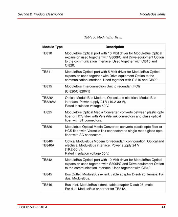
ModuleBus Items
The ModuleBus supports up to 8 cluster, one base cluster and up to 7 I/O cluster, connected to each other via optical cables, Optical ModuleBus Modems and a ModuleBus Optical port module. The cluster is built up by MTUs and/or S800L modules. At the last, MTU or S800L modules bus outlet a terminator module, TB807, must be inserted.
Mounting Kit
Used for horizontal mounting of CI801, CI840 and TB840 on a vertical DIN-rail.
Horizontal Mounting Profile
Mounting profile with one DIN-rail and one cable duct.
(1) Connector is not enclosed.(2) The three cable plugs are enclosed, see Table 4.(3) Connector is not enclosed. Three connectors are needed, see Table 4.
Table 4. Cable Connectors for TU813 and TU814, Supplied by Phoenix Contact
Part No Name
Cable plug TU813 1809792 MSTBC 2.5/8-STZF-5.08
Cable plug TU814 1808890 MSTBC 2.5/10-ST-5.08
Crimp snap in connector
1879531 MSTBC-MT 0.2-0.5
3190564 MSTBC-MT 0.5-1.0
3190551 MSTBC-MT 1.5-2.5
Crimping tool 1204038 CRIMPFOX MT 2.5
Remove insulation tool 1204384 QUICK WIREFOX 6
Table 3. S800M I/O Termination Units (Continued)
Module Type
Description
Section 2 Product Description ModuleBus Items
3BSE015969-510 A 41
Table 5. ModuleBus Items
Module Type Description
TB810 ModuleBus Optical port with 10 Mbit driver for ModuleBus Optical expansion used together with S800I/O and Drive equipment Option to the communication interface. Used together with CI810 and CI820.
TB811 ModuleBus Optical port with 5 Mbit driver for ModuleBus Optical expansion used together with Drive equipment Option to the communication interface. Used together with CI810 and CI820.
TB815 ModuleBus Interconnection Unit to redundant FCIs
(CI820/CI820V1)
TB820/TB820V2
Optical ModuleBus Modem. Optical and electrical ModuleBus interface. Power supply 24 V (19.2-30 V),Rated insulation voltage 50 V.
TB825 ModuleBus Optical Media Converter, converts between plastic opto fiber or HCS fiber with Versatile link connectors and glass optical fiber with ST connectors.
TB826 Modulebus Optical Media Converter, converts plastic opto fiber or HCS fiber with Versatile link connectors to single mode glass opto fiber with SC connectors.
TB840/TB840A
Optical ModuleBus Modem for redundant configuration. Optical and electrical ModuleBus interface. Power supply 24 V (19.2-30 V),Rated insulation voltage 50 V.
TB842 ModuleBus Optical port with 10 Mbit driver for ModuleBus Optical expansion used together with S800I/O and Drive equipment Option to the communication interface. Used together with CI840.
TB845 Bus Outlet. ModuleBus extent. cable adaptor D-sub 25, female. For dual ModuleBus.
TB846 Bus Inlet. ModuleBus extent. cable adaptor D-sub 25, male. For dual ModuleBus or carrier for TB842.

ModuleBus Items Section 2 Product Description
42 3BSE015969-510 A
TK811V015 Optical ModuleBus expansion cable with connectors,duplex cable plastic fibre1.5 m (4.9 ft.)
TK811V050 Optical ModuleBus expansion cable with connectors,duplex cable plastic fibre 5 m (16.4 ft.)
TK811V150 Optical ModuleBus expansion cable with connectors,duplex cable plastic fibre 15 m (49.2 ft.)
TK812V015 Optical ModuleBus expansion cable with connectors,Optical simplex cable plastic fibre, 1.5 m (4.9 ft.)
TK812V050 Optical ModuleBus expansion cable with connectors,Optical simplex cable plastic fibre, 5 m (16.4 ft.)
TK812V150 Optical ModuleBus expansion cable with connectors,Optical simplex cable plastic fibre, 15 m (492 ft.)
TB805 Bus Outlet. ModuleBus extent, cable adaptor D-sub 25, female. For single ModuleBus.
TB806 Bus Inlet. ModuleBus extent. cable adaptor D-sub 25, male. For single ModuleBus or carrier for TB842.
TB807 ModuleBus terminator. One each per base and I/O cluster.
TK801V003 ModuleBus extension cable.Shielded Cable 0.3m (1.0 ft.), D-sub 25, male, female.
TK801V006 ModuleBus extension cableShielded cable 0.6m (2.0 ft.) D-sub 25, male, female.
TK801V012 ModuleBus extension cableShielded cable 1.2m (4.0 ft.) D-sub 25, male, female.
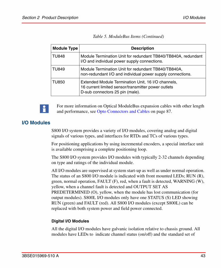
TU807 Module Termination Unit for single TB840/TB840A.
TU840 Module Termination Unit for redundant TB840/TB840A, redundant I/O.
TU841 Module Termination Unit for redundant TB840/TB840A, non-redundant I/O.
Table 5. ModuleBus Items (Continued)
Module Type Description
Section 2 Product Description I/O Modules
3BSE015969-510 A 43
I/O Modules
S800 I/O system provides a variety of I/O modules, covering analog and digital signals of various types, and interfaces for RTDs and TCs of various types.
For positioning applications by using incremental encoders, a special interface unit is available comprising a complete positioning loop.
The S800 I/O system provides I/O modules with typically 2-32 channels depending on type and ratings of the individual module.
All I/O modules are supervised at system start-up as well as under normal operation. The status of an S800 I/O module is indicated with front mounted LEDs; RUN (R), green, normal operation, FAULT (F), red, when a fault is detected, WARNING (W), yellow, when a channel fault is detected and OUTPUT SET AS PREDETERMINED (O), yellow, when the module has lost communication (for output modules). S800L I/O modules only have one STATUS (S) LED showing RUN (green) and FAULT (red). All S800 I/O modules (except S800L) can be replaced with both system power and field power connected.
Digital I/O Modules
All the digital I/O modules have galvanic isolation relative to chassis ground. All modules have LEDs to indicate channel status (on/off) and the standard set of
TU848 Module Termination Unit for redundant TB840/TB840A, redundant I/O and individual power supply connections.
TU849 Module Termination Unit for redundant TB840/TB840A, non-redundant I/O and individual power supply connections.
TU850 Extended Module Termination Unit, 16 I/O channels,16 current limited sensor/transmitter power outletsD-sub connectors 25 pin (male).
For more information on Optical ModuleBus expansion cables with other length and performance, see Opto Connectors and Cables on page 87.
Table 5. ModuleBus Items (Continued)
Module Type Description

I/O Modules Section 2 Product Description
44 3BSE015969-510 A
module status indicators. Some output modules and modules with Intrinsic Safety interfaces have indication for the channel error status.
The S800 I/O modules 24/48 V d.c. have channels isolated in groups. Each group has a field power status input to indicate presence of field power. The loss of field power is indicated on Warning LED, module status set to warning and channel status set to error.
The 120/250 V a.c. or d.c. modules have individually isolated channels. The input module can be configured to monitor field power status.
S800L I/O modules 24 V d.c. have one isolated group with 16 channels, used together with TU805 enable 2-and 3-wires connections. The input modules can be configured to monitor field power status. Loss of field power will set module status to warning and channel status to error.
Outputs do not need external inductive load suppression components.
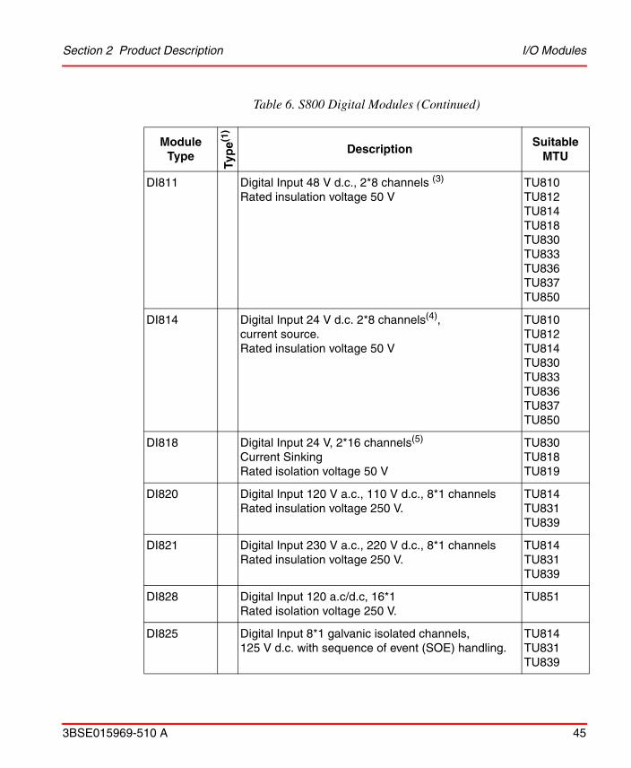
Table 6. S800 Digital Modules
Module Type
Typ
e(1)
DescriptionSuitable
MTU
DI801 L Digital Input 24 V d.c., 1*16 channels (2)
Rated insulation voltage 50 V
(3)
DI802 L Digital input 120 V a.c., 110 V d.c. 8*1 channelsRated insulation voltage 250 V
DI803 L Digital input 230 V a.c., 220 V d.c. 8*1 channelsRated insulation voltage 250 V
DI810 Digital Input 24 V d.c., 2*8 channels (4)
Rated insulation voltage 50 VTU810TU812TU814TU818TU830TU833TU836TU837TU850
Section 2 Product Description I/O Modules
3BSE015969-510 A 45
DI811 Digital Input 48 V d.c., 2*8 channels (3)
Rated insulation voltage 50 VTU810TU812TU814TU818TU830TU833TU836TU837TU850
DI814 Digital Input 24 V d.c. 2*8 channels(4), current source. Rated insulation voltage 50 V
TU810TU812TU814TU830TU833TU836TU837TU850
DI818 Digital Input 24 V, 2*16 channels(5)
Current SinkingRated isolation voltage 50 V
TU830TU818TU819
DI820 Digital Input 120 V a.c., 110 V d.c., 8*1 channels Rated insulation voltage 250 V.
TU814TU831TU839
DI821 Digital Input 230 V a.c., 220 V d.c., 8*1 channels Rated insulation voltage 250 V.
TU814TU831TU839
DI828 Digital Input 120 a.c/d.c, 16*1Rated isolation voltage 250 V.
TU851
DI825 Digital Input 8*1 galvanic isolated channels, 125 V d.c. with sequence of event (SOE) handling.
TU814TU831TU839
Table 6. S800 Digital Modules (Continued)
Module Type
Typ
e(1)
DescriptionSuitable
MTU
I/O Modules Section 2 Product Description
46 3BSE015969-510 A
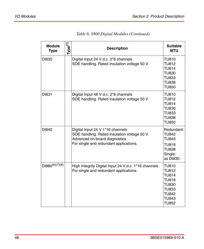
DI830 Digital Input 24 V d.c. 2*8 channelsSOE handling. Rated insulation voltage 50 V
TU810TU812TU814TU830TU833TU838TU850
DI831 Digital Input 48 V d.c. 2*8 channelsSOE handling. Rated insulation voltage 50 V
TU810TU812TU814TU830TU833TU838TU850
DI840 Digital Input 24 V 1*16 channelsSOE handling. Rated insulation voltage 50 V. Advanced on-board diagnostics.For single and redundant applications.
Redundant:TU842TU843
TU818TU838Single:as DI830
DI880(6)(7)(8) High Integrity Digital Input 24 V d.c. 1*16 channelsFor single and redundant applications.
TU810TU812TU814TU818TU830TU833TU842TU843TU852
Table 6. S800 Digital Modules (Continued)
Module Type
Typ
e(1)
DescriptionSuitable
MTU

Section 2 Product Description I/O Modules
3BSE015969-510 A 47
DI885 Digital Input 24/48 V d.c.1*8 channels open-circuitmonitoring, SOE handling. Rated insulation voltage 50 V
TU810TU812TU814TU818TU830TU833
DI890 Digital Input, I.S. interface, 8*1 channelsGalvanic insulation between channels.Rated insulation voltage 50 V.
TU890TU891
DO801 L Digital Output 24 V d.c. 0.5 A protected,1*16 channels(2)
Rated insulation voltage 50 V
(3)
DO802 L Digital Output Relay 8*1 channels, 24-230 V a.c./110 V d.c. 2 A cos d.c. < 60 W.Varistor protectedRated insulation voltage 250 V.
DO810 Digital Output 24 V d.c. 0.5 A protected,2*8 channels(4)
Rated insulation voltage 50 V.
TU810TU812TU814TU830TU833
DO814 Digital Output 24 V d.c. 0.5 A protected,2*8 channels(4), current sinkRated insulation voltage 50 V
TU810TU812TU814TU830TU833
DO815(9) Digital Output 24 V d.c. 2 A protected,2*4 channels.Rated insulation voltage 50 V.
TU810TU812TU814TU830TU833
Table 6. S800 Digital Modules (Continued)
Module Type
Typ
e(1)
DescriptionSuitable
MTU

I/O Modules Section 2 Product Description
48 3BSE015969-510 A
DO818 Digital Output 24 V d.c. 0.5 A protected,2*16 channels(5)
Rated insulation voltage 50 V.
TU830TU818TU819
DO820 Digital Output Relay 8*1 channels 24-230 V a.c.3 A cos 0.4 d.c. < 42W. Varistor protectedRated insulation voltage 250 V.
TU811TU813TU831TU836TU837
DO821 Digital Output Relay 8*1 normally closed channels24-230 V a.c./d.c. 3 A cos 0.5 d.c. < 42 WVaristor protectedRated insulation voltage 250 V
TU811TU813TU831TU836TU837TU851
DO828 Digital Output Relay 16*1 channels125Vd.c./250V a.c.Rated isolation voltage 250 V.
TU851
DO840 Digital Output 24 V d.c. 0.5 A protected, 2*8 channels Rated insulation voltage 50 V.Advanced on-board diagnostics.For single and redundant applications.
Redundant:TU842TU843TU852Single:as DO810
DO880(6) High Integrity Digital Output 24 V d.c. 1*16 channelsFor single and redundant applications.
See DO840
DO890 Digital Output 11 V 40 mA, I.S. interface, 4*1 channelsGalvanic isolation between channelsRated insulation voltage 50 V
TU890TU891
Table 6. S800 Digital Modules (Continued)
Module Type
Typ
e(1)
DescriptionSuitable
MTU
Section 2 Product Description I/O Modules
3BSE015969-510 A 49
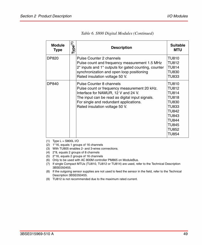
DP820 Pulse Counter 2 channelsPulse count and frequency measurement 1.5 MHz2* inputs and 1* outputs for gated counting, counter synchronization and open loop positioningRated insulation voltage 50 V.
TU810TU812TU814TU830TU833
DP840 Pulse Counter 8 channelsPulse count or frequency measurement 20 kHz.Interface for NAMUR, 12 V and 24 V.The input can be read as digital input signals.For single and redundant applications.Rated insulation voltage 50 V.
TU810TU812TU814TU818TU830TU833TU842TU843TU844TU845TU852TU854
(1) Type L = S800L I/O (2) 1*16, equals 1 groups of 16 channels(3) With TU805 enables 2- and 3-wires connections.(4) 2*8, equals 2 groups of 8 channels(5) 2*16, equals 2 groups of 16 channels(6) Only to be used with AC 800M controller PM865 on ModuleBus.(7) If single Compact MTUs (TU810, TU812 or TU814) are used, refer to the Technical Description
3BSE050455.(8) If the outgoing sensor supplies are not used to feed the sensor in the field, refer to the Technical
Description 3BSE050455.(9) TU812 is not recommended due to the maximum rated current.
Table 6. S800 Digital Modules (Continued)
Module Type
Typ
e(1)
DescriptionSuitable
MTU
I/O Modules Section 2 Product Description
50 3BSE015969-510 A
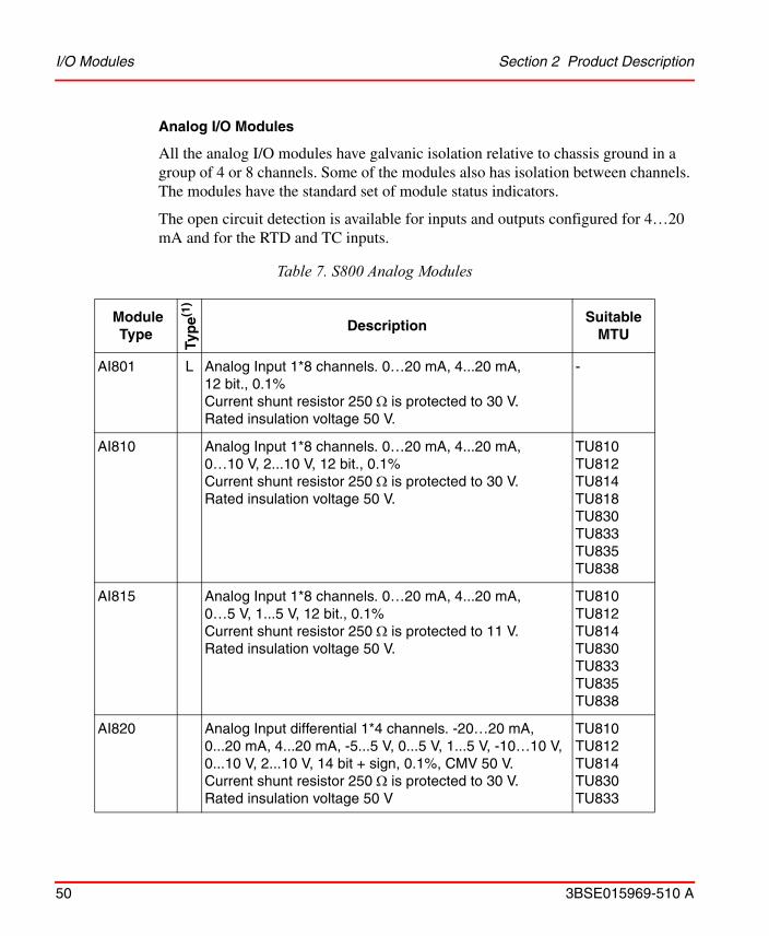
Analog I/O Modules
All the analog I/O modules have galvanic isolation relative to chassis ground in a group of 4 or 8 channels. Some of the modules also has isolation between channels. The modules have the standard set of module status indicators.
The open circuit detection is available for inputs and outputs configured for 4…20 mA and for the RTD and TC inputs.
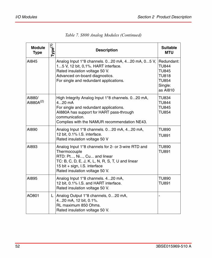
Table 7. S800 Analog Modules
Module Type
Typ
e(1)
DescriptionSuitable
MTU
AI801 L Analog Input 1*8 channels. 0…20 mA, 4...20 mA, 12 bit., 0.1% Current shunt resistor 250 is protected to 30 V. Rated insulation voltage 50 V.
-
AI810 Analog Input 1*8 channels. 0…20 mA, 4...20 mA,0…10 V, 2...10 V, 12 bit., 0.1% Current shunt resistor 250 is protected to 30 V. Rated insulation voltage 50 V.
TU810 TU812 TU814TU818TU830 TU833 TU835 TU838
AI815 Analog Input 1*8 channels. 0…20 mA, 4...20 mA,0…5 V, 1...5 V, 12 bit., 0.1% Current shunt resistor 250 is protected to 11 V. Rated insulation voltage 50 V.
TU810 TU812 TU814 TU830 TU833 TU835 TU838
AI820 Analog Input differential 1*4 channels. -20…20 mA, 0...20 mA, 4...20 mA, -5...5 V, 0...5 V, 1...5 V, -10…10 V, 0...10 V, 2...10 V, 14 bit + sign, 0.1%, CMV 50 V.Current shunt resistor 250 is protected to 30 V. Rated insulation voltage 50 V
TU810 TU812 TU814 TU830 TU833

Section 2 Product Description I/O Modules
3BSE015969-510 A 51
AI825 Analog Input 4*1 channels for applications requiring galvanic isolated channels, -20...20 mA, 0(4)...20 mA, -10...10V, 0(2)...10 V
TU811 TU813 TU831
AI830/AI830A
Analog Input 1*8 ch, Pt100 (-80...80oC, -200...250oC,-200...850oC), Ni100 (-60...180oC), Ni120 (-80...260oC), Cu10 (-100...260oC)Resistor (0...400 ), 14 bit.Pt100 according to IEC751 ITPS-68, IEC ITP-90, US Ind Std, US lab Std, JIS C 1604:1981 and JIS C 1604:1997Ni100 according to DIN 43760Ni120 according to MIL-T-24388CCu10 according to TCR 0.00427Rated insulation voltage 50 V.
TU810 TU812 TU814 TU830 TU833
AI835/AI835A
Analog Input 1*8 ch Thermocouple (TC), type B (0...1820oC), type C (0...2300oC), type E (-270...1000oC), type J (-210...1200oC), type K (-270...1372oC), type N (-270...1300oC), type R (-50...1768oC), type S (-50...1768oC), type T (-270...400oC), linear -30...75 mV, 14 bit. Rated insulation voltage 50 V.
TU810 TU812 TU814TU818TU830 TU833
AI843 Analog Input 1*8 ch Thermocouple (TC), -30 mV to 75 mV linear, or TC types B, C, E, J, K, L, N, R, S, T, and U, 16 bit. Rated insulation voltage 50 VAdvanced on-board diagnostics.For single and redundant applications.
TU818TU830 TU833 TU842 TU843TU852
Table 7. S800 Analog Modules (Continued)
Module Type
Typ
e(1)
DescriptionSuitable
MTU
I/O Modules Section 2 Product Description
52 3BSE015969-510 A
AI845 Analog Input 1*8 channels. 0...20 mA, 4...20 mA, 0...5 V, 1...5 V, 12 bit, 0,1%. HART interface.Rated insulation voltage 50 V.Advanced on-board diagnostics.For single and redundant applications.
Redundant:TU844 TU845TU818TU854Single:as AI810
AI880/AI880A(2)
High Integrity Analog Input 1*8 channels. 0...20 mA, 4...20 mAFor single and redundant applications.AI880A has support for HART pass-through communication.Complies with the NAMUR recommendation NE43.
TU834 TU844 TU845TU854
AI890 Analog Input 1*8 channels. 0…20 mA, 4...20 mA,12 bit, 0.1% I.S. interface.Rated insulation voltage 50 V
TU890
TU891
AI893 Analog Input 1*8 channels for 2- or 3-wire RTD and ThermocoupleRTD: Pt..., Ni..., Cu... and linearTC: B, C, D, E, J, K, L, N, R, S, T, U and linear15 bit + sign, I.S. interfaceRated insulation voltage 50 V.
TU890 TU891
AI895 Analog Input 1*8 channels. 4...20 mA, 12 bit, 0.1% I.S. and HART interface.Rated insulation voltage 50 V.
TU890TU891
AO801 L Analog Output 1*8 channels, 0…20 mA, 4...20 mA, 12 bit, 0.1%. RL maximum 850 Ohms.Rated insulation voltage 50 V.
-
Table 7. S800 Analog Modules (Continued)
Module Type
Typ
e(1)
DescriptionSuitable
MTU

Section 2 Product Description I/O Modules
3BSE015969-510 A 53
AO810/AO810V2
Analog Output 1*8 channels, 0…20 mA, 4...20 mA, 14 bit, 0.1%. RL maximum 500/850 Ohms.Rated insulation voltage 50 V.
TU810TU812TU814TU830TU833
AO815 Analog Output 1*8 channels, 4...20 mA, 14 bit, 0.1%. RL maximum 750 Ohms.Rated insulation voltage 50 V.
TU810TU812TU814TU830TU833
AO820 Analog Output 4*1 channels, -20…20 mA, 0...20 mA, 4...20 mA, -10…10 V, 0...10 V, 2...10 V, 12 bit + sign, 0.1%, individually isolated.Current output RL maximum 550 Ohms.Voltage output RL minimum 2 kohms.Rated insulation voltage 50 V.
TU810TU812TU814TU830TU833
AO845/AO845A
Analog Output 1*8 channels. 4...20 mA, 12 bit, 0,1%. HART interface, RL maximum 750 Ohms.
Rated insulation voltage 50 V.Advanced on-board diagnostics.For single and redundant applications.
Redundant:TU842TU843TU852Single:as AO810/AO810V2
AO890 Analog Output 1*8 channels. 0…20 mA, 4...20 mA, 12 bit, 0.1% I.S. interface, RL maximum 750 Ohms.Rated insulation voltage 50 V
TU890
TU891
AO895 Analog Output 1*8 channels. 4...20 mA, 12 bit, 0.1%I.S.and HART interface, RL maximum 750 Ohms.Rated insulation voltage 50 V.
TU890
TU891
(1) Type L = S800L I/O(2) Only to be used with AC 800M controller PM865 on ModuleBus.
Table 7. S800 Analog Modules (Continued)
Module Type
Typ
e(1)
DescriptionSuitable
MTU
Drives Integration Section 2 Product Description
54 3BSE015969-510 A
Drives Integration
The ABB Standard and Engineered drives can be connected to the S800 I/O system.The FCI works as a communication link between the fieldbus master and the drives. No application software concerning this functionality is stored in the FCI. Check the available support for each FCI type.
The following drives are considered to be standard drives:
• ACS400 with standard drive
• ACS600/800 with standard application
• ACS600/800 with crane application
• ACS600/800 with pump and fan application (PFC)
• DCS400/500 with standard drive
• DCS600 with crane application
The following drives are considered to be engineered drives:
• ACS600/800 with system application
• ACS600/800 with system application (PMSM)
• ACS600/800 IGBT with supply (ISU) application
• ACS600/800 with Multi Block Programming application ABxR7xxx
• ACS800 with crane application
• ACS800 Rolling Mill Application (RMO) A4xR7xxx
• ACS800LC DSU with diode supply unit applications
• ACS6000C with cyclo converter drive
• ACS6000SD with synchronous drive
• ACS6000AD with asynchronous drive
• ACS1000 with standard drive
• DCS600 with system application
• DCS600 with crane application

Section 2 Product Description Drives Integration
3BSE015969-510 A 55
Product Benefits
By integrating drives and the control system, full advantage can be taken to added functions. The process data are measured with improved accuracy for even more exact process control, while the ready-made information permits a total overview of the drives in the process.
Features
The ABB drives integration includes features such as:
• Fieldbus solutions which results in lower wiring costs.
• Optical transmission between FCI and drives allows installations in an electrical disturbed environment.
• Faults in drives available as alarms and in diagnostic displays reduces troubleshooting and maintenance costs.
• Warnings from drives available as events and in diagnostic displays, allows the operator to determine, when preventive service is needed.
• Predefined type circuit solutions reduces project engineering and commissioning.
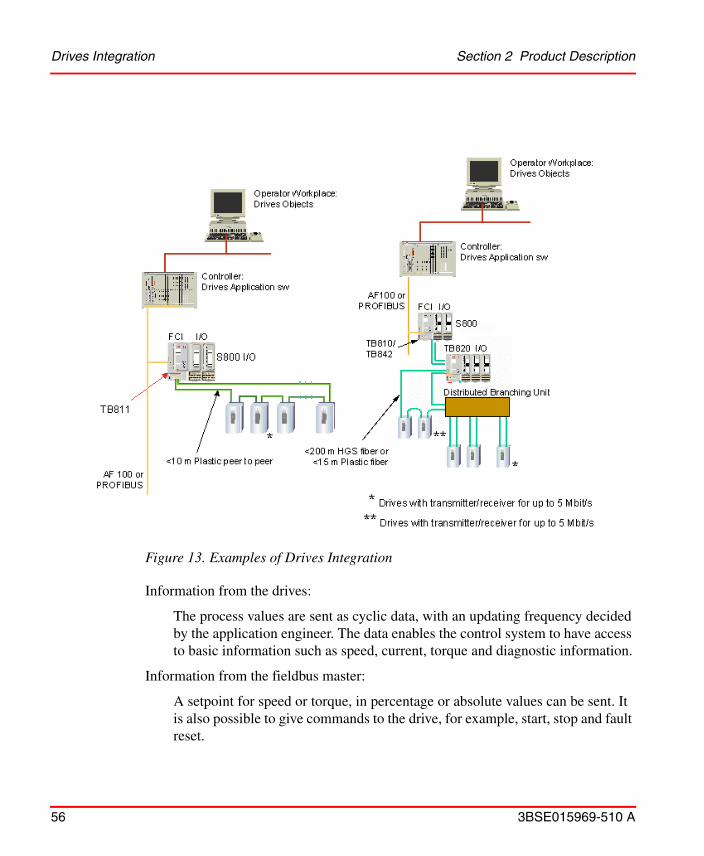
The connection is made directly to the drives system through an optical ring or a star by using a Distributed Branching Unit. One important aspect is the simplicity in the connection. No extra hardware is needed in any of the devices, that is, the functions are included in the basic products, minimizing communication delays and cost.
Drives Integration Section 2 Product Description
56 3BSE015969-510 A
Information from the drives:
The process values are sent as cyclic data, with an updating frequency decided by the application engineer. The data enables the control system to have access to basic information such as speed, current, torque and diagnostic information.
Information from the fieldbus master:
A setpoint for speed or torque, in percentage or absolute values can be sent. It is also possible to give commands to the drive, for example, start, stop and fault reset.
Figure 13. Examples of Drives Integration

Section 2 Product Description Support for connections to instruments in Hazardous Areas
3BSE015969-510 A 57
Support for connections to instruments in Hazardous Areas
S800 I/O provide two possibilities to connections of instruments in Hazardous areas, both integrated with special I/O modules and with support for external Intrinsic Safety systems.
The S800 I/O includes I/O modules and MTU with Intrinsic Safety interfaces, namely AI890, AI893, AI895, AO890, AO895, DI890, DO890 and TU890. The interfaces are classified Ex ia, Group IIC and the modules are ATEX certified.
The correct and safe operation of the Intrinsic Safety aspects of MTU and I/O Modules with Intrinsic Safety interfaces calls for expert installation and commissioning as well as correct operation and meticulous maintenance. Only those persons conversant with the installation commissioning, operation and maintenance of similar apparatus and who has the necessary qualifications should work on these products.
Ensure that the installation is carried out observing the safety regulations pertaining to the installation, operation of electrical systems, and the directives and guidelines on explosion protection (Hazardous Area equipment should comply with the descriptive system document).
The set of I/O modules and MTUs are not intended for hazardous area installation unless it is included in a suitable enclosure which conforms to the applicable standards. To mount the equipment in a Zone2 hazardous area then an enclosure or cabinet which provides ingress protection of IP54 rating is required.
For I.S. applications, the maximum limit for AC power supply is 250 Vrms and the user must ensure that the DC power supply to the FCI and I/O is limited to 60 V.
TB810 and TB842 are equipped with a transmitter/receiver for up to 10 Mbit/s and TB811 for up to 5 Mbit/s. A ModuleBus must have the same type of transmitter/receiver on each node.

Support for Externally Connected Accessories Section 2 Product Description
58 3BSE015969-510 A
Support for Externally Connected Accessories
Connection to External Intrinsic Safety System
The Intrinsic Safety System from Pepperl+Fuchs (manufacturer outside ABB) is supported via S800 I/O modules and a special MTU.
The supported Intrinsic Safety System is the HiD Series 2000.
The S800 I/O modules are connected via MTU TU812/TU812V1, a standard cable from Pepperl+Fuchs and a specific adapter board, one for each I/O module types according to Table 8. The standards of cables - 0.2 m (0.66 ft) and 1.3 m (4.3 ft). The maximum cable length is 100 m (109 yd).
Table 8. Supported Modules and Intrinsic Safety Components
ABB delivery Pepperl+Fuchs delivery
S800 I/O module
Terminal unit
Termination and adaptor board
Intrinsic Safety modules
Note
AI810 TU812 2108/HAT/ABB-AI-H-01 2026, 2030, 2062, 2072 Dual channel modules
2108/HAKE/ABB-AI-H-01(1)
(1) Loop-disconnected terminals
2026, 2030 using passive connection
Dual channel modules
AO810/AO810V2
TU812 2108/HAT/ABB-AO-H-01 2032, 2034, 2038 Dual channel modules
2108/HAKE/ABB-AO-H-01(1) 2032, 2034, 2038 Dual channel modules
DI810 TU812 2108/HAT/ABB-DI-01 2824, 2844 Quad channel modules
DO810 TU812 2108/HAT/ABB-DO-01 2872, 2874, 2876, 2878 Dual channel modules
2108/HAKE/ABB-DO-H-01(1) 2872, 2874, 2876, 2878 Dual channel modules

Section 2 Product Description Support for Externally Connected Accessories
3BSE015969-510 A 59
Pepperl+Fuchs can provide a HART protocol connection to I/O modules integrated with the Intrinsic Safety system using the MUX 2700 Remote Board for HART.
Connection to ABB Entrelec Interfast Pre-wiring Solutions
ABB Entrelec offers solutions for fast termination solutions with pre-wired cables and an assortment of terminations and signal adaptions. This offer connects to S800 I/O via the TU812 termination unit which provides a D-sub connector. Multipurpose cables are also available. Further information is available in the ABB Entrelec catalog "Pre-wiring system for PLC's, Interfast", 1SNC127001C0206.
Connection to Phoenix Contact Varioface solutions
The Phoenix Contact offers solutions for fast termination solutions with pre-wired cables and an assortment of terminations and signal adaptions. This offer connects
Figure 14. Example of Connection between S800 I/O andIntrinsic Safety System from Pepperl+Fuchs
Figure 15. Example of Connection between S800 I/O andIntrinsic Safety System and HART Protocol Connection

Support for HART Communication Section 2 Product Description
60 3BSE015969-510 A
to S800 I/O via the TU812 termination unit which provides a D-sub connector. For further information, refer the link www.s800connection.com.
Support for HART Communication
S800 I/O provides possibilities to communicate via HART protocol with HART Field Devices via PROFIBUS-DPV1 using CI840 or CI801 or AF100 using CI810 or CI820. There are four I/O modules that have HART interface, AI815, AI845, AO815, AO845, AO845A, AI895 and AO895.
For HART connection via external HART MUX, see Support for connections to instruments in Hazardous Areas on page 57.
S800 I/O provides the possibilities for HART communication, but the user function is defined by the system (operator stations and controllers) S800 I/O is included in. Always read the relevant system documentation for information about the supported features and needed components of S800 I/O.
On PROFIBUS, an Extended HART mode gives a possibility to pass-through long HART data frames up to 227 bytes. This will reduce the possible amount of I/O modules per station. The longest HART data frame without the Extended HART mode is 64 bytes.
Section 2 Product Description Support for Safety System Requirements
3BSE015969-510 A 61
Support for Safety System Requirements
The High Integrity I/O is certified for EN 61508-SIL3. The High Integrity I/O has to be used together with a certified controller to comply with the standards. There are three modules that belong to the High Integrity I/O family that are certified for these standards, AI880/AI880A, DI880 and DO880. The modules are supported by the AC 800M controller PM865 only and have to use the Optical ModuleBus Modem TB840 when adding optical clusters.
Redundancy Functionality
Fieldbus Communication Interface (FCI)
When using redundant FCI, one is primary and one is secondary. If the primary FCI fails it will hand over to the secondary FCI.
If using redundant FCI and redundant electrical ModuleBus, the primary FCI will control both electrical ModuleBuses. When the primary FCI fails, the secondary FCI will take control of both electrical ModuleBuses.
Input Modules
When using redundant input modules, all reading is done from the primary input module. The input module will diagnose itself, and when the primary input module fails the secondary input module will be set as primary instead.
The secondary input module is checked for error status at a lower cycle rate than the primary.
Analog Output Modules
When using redundant AO modules, half the output current is generated from each AO module. The AO module will diagnose itself, and when one fails, it disconnects and a direct communication between the two redundant AO modules will ensure that the second AO module quickly doubles its output current.
Make sure installation is carried out observing the requirement and guidelines in the documentation.
FCIs and TB820 cannot handle High Integrity I/O modules.
Software Components Section 2 Product Description
62 3BSE015969-510 A
Digital Output Module
When using redundant DO modules, they both work parallel to each other. They give the same output, and the small time difference between them, in setting a signal high or low, does not make a difference.
When one DO module fails it will give output signals set to low. The DO module that still work will override by setting some signals to high.
Software Components
Fieldbus Communication Interface
The system software of a Fieldbus Communication Interface comprises a real-time operating system. The software is installed at delivery.
The upgrades are available for download for the system software for field upgrade. The cables to connect a standard PC with the FCI are available in the S800 I/O price list.
Section 2 Product Description Hardware Components
3BSE015969-510 A 63
Hardware ComponentsThe highly modularized hardware of S800 I/O includes the following components:
• I/O Modules
• Module Termination Units (MTUs).
• Fieldbus Communication Interface
• ModuleBus Items
The communication interface modules, Optical ModuleBus Modem, MTUsand S800 I/O modules are mounted on standard DIN-mounting rails according to EN50022 NS 35/7,5.
An S800 I/O station can consist of a base cluster and up to 7 additional I/O clusters. The base cluster consists of a communication interface module and up to 12 I/O modules. I/O cluster 1 to 7 consist of an Optical ModuleBus Modem and up to 12 I/O modules. An S800 I/O station can have up to 24 I/O modules in total. I/O cluster 1 to 7 are connected to the communication interface module through an optical expansion of the ModuleBus.
I/O Modules
There are two types of S800 I/O modules:
• S800 I/O modules designed to be used together with the Module Termination Units. See Figure 20 and Figure 22.
• S800L I/O modules
– designed to be directly mounted on a standard DIN-rail and containing process connection, via detachable connectors. The S800L modules have only mechanical lock device and cannot be removed with power on.
– as accessories to 24 V DI/DO modules, Terminal Unit TU805 enables 2- and 3-wires connections, see Figure 17.
I/O Modules Section 2 Product Description
64 3BSE015969-510 A
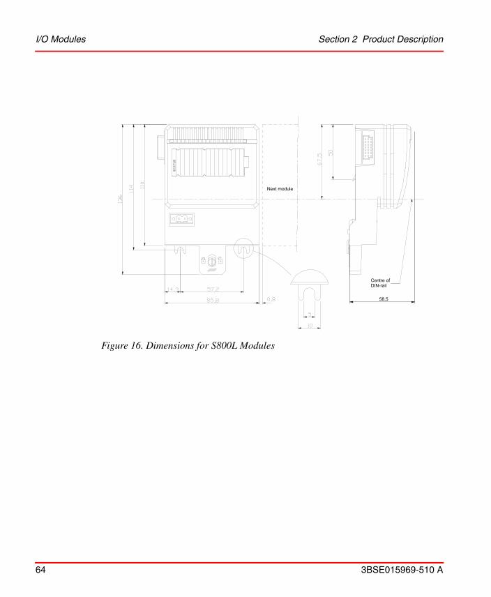
Figure 16. Dimensions for S800L Modules
58,5
Centre of DIN-rail
Next module
Section 2 Product Description Module Termination Unit
3BSE015969-510 A 65
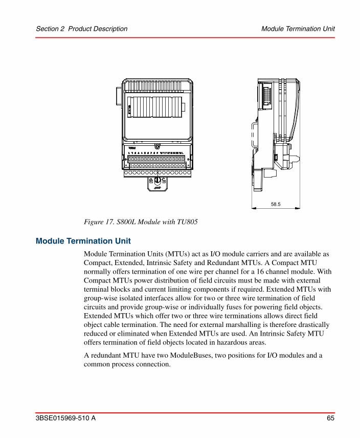
Module Termination Unit
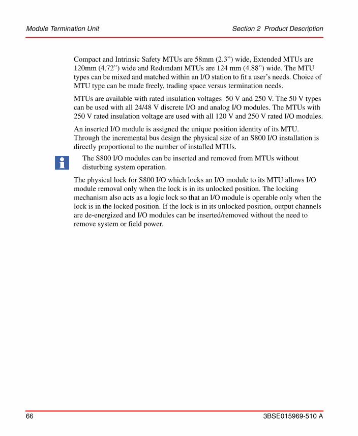
Module Termination Units (MTUs) act as I/O module carriers and are available as Compact, Extended, Intrinsic Safety and Redundant MTUs. A Compact MTU normally offers termination of one wire per channel for a 16 channel module. With Compact MTUs power distribution of field circuits must be made with external terminal blocks and current limiting components if required. Extended MTUs with group-wise isolated interfaces allow for two or three wire termination of field circuits and provide group-wise or individually fuses for powering field objects. Extended MTUs which offer two or three wire terminations allows direct field object cable termination. The need for external marshalling is therefore drastically reduced or eliminated when Extended MTUs are used. An Intrinsic Safety MTU offers termination of field objects located in hazardous areas.
A redundant MTU have two ModuleBuses, two positions for I/O modules and a common process connection.
Figure 17. S800L Module with TU805
58.5
Module Termination Unit Section 2 Product Description
66 3BSE015969-510 A
Compact and Intrinsic Safety MTUs are 58mm (2.3”) wide, Extended MTUs are 120mm (4.72”) wide and Redundant MTUs are 124 mm (4.88”) wide. The MTU types can be mixed and matched within an I/O station to fit a user’s needs. Choice of MTU type can be made freely, trading space versus termination needs.
MTUs are available with rated insulation voltages 50 V and 250 V. The 50 V types can be used with all 24/48 V discrete I/O and analog I/O modules. The MTUs with 250 V rated insulation voltage are used with all 120 V and 250 V rated I/O modules.
An inserted I/O module is assigned the unique position identity of its MTU. Through the incremental bus design the physical size of an S800 I/O installation is directly proportional to the number of installed MTUs.
The physical lock for S800 I/O which locks an I/O module to its MTU allows I/O module removal only when the lock is in its unlocked position. The locking mechanism also acts as a logic lock so that an I/O module is operable only when the lock is in the locked position. If the lock is in its unlocked position, output channels are de-energized and I/O modules can be inserted/removed without the need to remove system or field power.
The S800 I/O modules can be inserted and removed from MTUs without disturbing system operation.
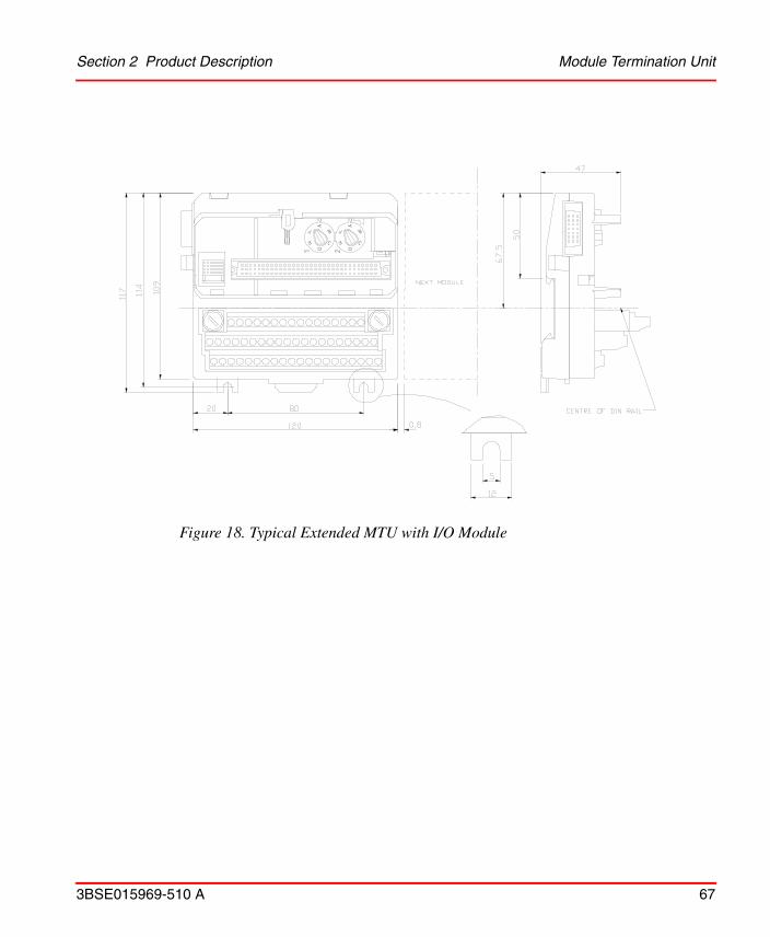
Section 2 Product Description Module Termination Unit
3BSE015969-510 A 67
Figure 18. Typical Extended MTU with I/O Module

Module Termination Unit Section 2 Product Description
68 3BSE015969-510 A
Figure 19. Typical Compact MTU with I/O Module

Section 2 Product Description Module Termination Unit
3BSE015969-510 A 69
Figure 20. Compact MTU for Intrinsic Safety without and with I/O Module
ABC
D
E F
A
BC
D
E F
192
mm
58.5 mm
9 mm
7 mm
31.5 mm
(.27”)
(7.6
”)
(2.30”)
(0.35”)
(1.24")58 mm(2.28”)
122 mm(4.8”)
(4.6
8”)
119
mm
40 mm(1.57”)
5 mm(0.2”)
92.5
mm
(3.6
4”)
99.
5 m
m
(3.9
2”)
Center ofDIN-rail
8 mm (0.31”)

Module Termination Unit Section 2 Product Description
70 3BSE015969-510 A
Figure 21. Typical Horizontal Redundant MTU
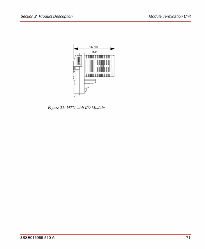
Section 2 Product Description Module Termination Unit
3BSE015969-510 A 71
Figure 22. MTU with I/O Module
122 mm
(4.8”)
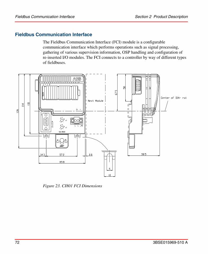
Fieldbus Communication Interface Section 2 Product Description
72 3BSE015969-510 A
Fieldbus Communication Interface
The Fieldbus Communication Interface (FCI) module is a configurable communication interface which performs operations such as signal processing, gathering of various supervision information, OSP handling and configuration of re-inserted I/O modules. The FCI connects to a controller by way of different types of fieldbuses.
Figure 23. CI801 FCI Dimensions

Section 2 Product Description Fieldbus Communication Interface
3BSE015969-510 A 73
Figure 24. CI810 FCI Dimensions
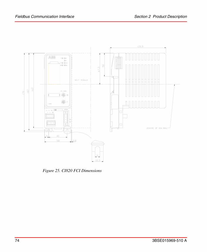
Fieldbus Communication Interface Section 2 Product Description
74 3BSE015969-510 A
Figure 25. CI820 FCI Dimensions
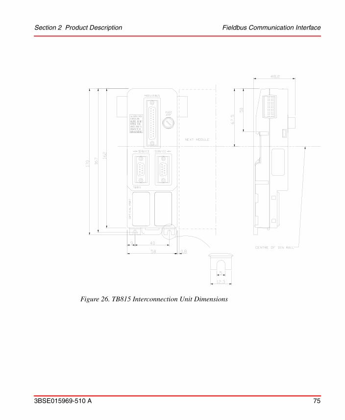
Section 2 Product Description Fieldbus Communication Interface
3BSE015969-510 A 75
Figure 26. TB815 Interconnection Unit Dimensions

Fieldbus Communication Interface Section 2 Product Description
76 3BSE015969-510 A
Figure 27 shows the TB815 configured with two CI820 FCIs for redundant operation.
Figure 28 shows the MTU TU847 (TU846) with redundant CI840. TU847 has one ModuleBus and are used for single I/O modules. TU846 has two ModuleBuses and are used for redundant I/O modules.
Figure 27. Redundant CI820 FCIs and TB815 Interconnection Unit Layout
Tx
Rx
MODULEBUS
SERVICE SERVICE
SBSA
L-L+L+
L-
STN. ADDR
F R
P
CI820
012
9
75
38
4 6
012
9
75
38
4 6
x 10
x 1
T1 T2
PR DU
SBSA
L-L+L+
L-
STN. ADDR
R
P
CI820
012
9
75
38
4 6
012
9
75
38
4 6
x 10
x 1
T2
DU
TB815
F
T1
PR
SWX.X/Y SWX.X/Y
+
-
SH
SH
AF100
+
-
SH
SH
AF100
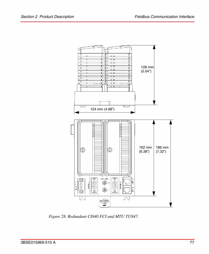
Section 2 Product Description Fieldbus Communication Interface
3BSE015969-510 A 77
Figure 28. Redundant CI840 FCI and MTU TU847.
124 mm (4.88”)
128 mm
162 mm
(5.04”)
(6.38”)186 mm(7.32”)

Fieldbus Communication Interface Section 2 Product Description
78 3BSE015969-510 A
S800M I/O modules may be exchanged during system operation. A module locking mechanism disconnects ModuleBus and process signals safely from the module. A newly inserted I/O module is automatically put into operation if the system identifies the module being correct type and without faults.
Figure 29. Dimension for typical MTU for CI840 or TB840

Section 2 Product Description ModuleBus
3BSE015969-510 A 79
ModuleBus
TB820/TB820V2 ModuleBus Modem
The TB820/TB820V2 ModuleBus Modem is a fiber optic interface to the ModuleBus. The ModuleBus Modem has an electrical and an optical interface which are logically the same bus. A maximum of 12 I/O modules can be connected to the electrical ModuleBus and up to seven clusters can be connected to the fiber optic ModuleBus.
The TB820/TB820V2 ModuleBus Modem has a rotary switch that selects its cluster number, 1 to 7, on the Optical ModuleBus.
The ModuleBus Modem communicates with the FCI or Controller via the Optical ModuleBus.
The TB820/TB820V2 ModuleBus Modem provides 24 V d.c. protected (from the source) and an isolated, protected 5 V d.c. power to the cluster’s I/O modules by way of the electrical ModuleBus connection. One power source (single or redundant 24 V d.c.) can be connected to the power terminals (L+ & L-). The redundant power supply can be supervised via inputs SA and SB.
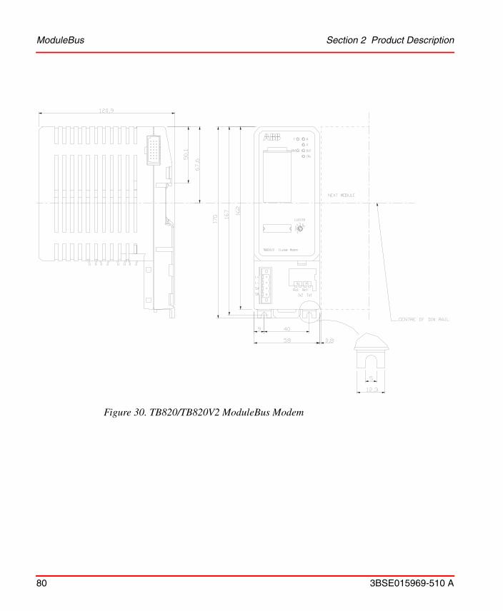
ModuleBus Section 2 Product Description
80 3BSE015969-510 A
Figure 30. TB820/TB820V2 ModuleBus Modem

Section 2 Product Description ModuleBus
3BSE015969-510 A 81
TB840/TB840A ModuleBus Modem and TU807/TU840/TU841/TU848/TU849 Module Termination Unit
The TB840/TB840A ModuleBus Modem is a fiber optic interface to the Optical ModuleBus. TB840/TB840A is used in redundancy configurations where each module is connected to different Optical ModuleBus lines, but connected to the same electrical ModuleBus.
Termination Unit TU840 connects TB840 to redundant I/O. Termination Unit TU841 connects TB840 to non-redundant I/O.
Termination unit TU848 has individual power supply connections and connects TB840 to redundant I/O. Termination unit TU849 has individual power supply connections and connects TB840 to non-redundant I/O. TB840 can be used as single with TU807.
The ModuleBus Modem has an electrical and an Optical ModuleBus interface which are logically the same bus. A maximum of 12 I/O modules can be connected to the electrical ModuleBus and up to seven clusters can be connected to the fiber optic ModuleBus.
The cluster address sets by a rotary switch on the Termination Unit TU807/TU840/TU841/TU848/TU849 in range 1 to 7.
The TB840/TB840A ModuleBus Modem provides 24 V d.c. protected (from the source) and an isolated, protected 5 V dc power to the cluster’s I/O modules by way of the electrical ModuleBus connection. One power source (single or redundant 24 V d.c.) can be connected to the power terminals (L+ & L-). The redundant power supply can be supervised via inputs SA and SB.
The rotary switch and the connectors for power supply is located on TU807/TU840/TU841/TU848/TU849. See Figure 31, for dimensions see also Figure 29.

ModuleBus Section 2 Product Description
82 3BSE015969-510 A
Figure 31. TB840 and TU840/TU841
124 mm (4.88”)
128 mm
47 mm
162 mm
(1.85”)
(5.04”)
(6.38”)186 mm(7.32”)
Only TU848/TU849

Section 2 Product Description ModuleBus
3BSE015969-510 A 83
TB825 Optical Media Converter
ModuleBus Optical Media Converter, converts between plastic opto fiber or HCS fiber with Versatile link connectors and glass optical fiber with ST connectors.
The TB825 is built in S800L mechanics and DIN-rail mounted.
Figure 32. TB825 Optical Media Converter
85.6
14.2
136
114
67.
5
57.258.5
ModuleBus Section 2 Product Description
84 3BSE015969-510 A
TB826 Optical Media Converter
TB826 is a Long Range Optical Media Converter for the ModuleBus. It is used to convert between plastic/opto fiber or HCS fiber with Versatile link connectors and single mode field fiber with SC connector.
The TB826 is built in S800L mechanics and DIN-rail mounted.
Figure 33. TB826 Optical Media Converter

Section 2 Product Description ModuleBus
3BSE015969-510 A 85
ModuleBus Optical Port, TB810/TB811
The ModuleBus Optical ports TB810/TB811 have two connectors for the Optical ModuleBus expansion and one connector for connection to the Fieldbus Communication Interface module, (FCI). The ModuleBus Optical ports are used together with the communication modules CI810, CI820/CI820V1 and (TB815).
TB810/TB811 is connected directly on the FCI.
Figure 34. ModuleBus Optical Port TB810/TB811
Rx
Tx
Tx Rx
20 mm (0,79”)
39,6
mm
(1,
6”)
39,6
mm
(1,
6”)

ModuleBus Section 2 Product Description
86 3BSE015969-510 A
ModuleBus Optical Port, TB842
The ModuleBus Optical port TB842 has two connectors for the Optical ModuleBus expansion and one connector for connection to the Fieldbus Communication Interface module, (FCI). The ModuleBus Optical ports are used together with the communication modules CI801 or CI840.
TB842 is connected to CI801 through TB806 and to CI840 through TB806 and TU847 or TB846 and TU846.
Figure 35. ModuleBus Optical Port TB842
17,6 mm
56,7
mm
42,3 mm

Section 2 Product Description ModuleBus
3BSE015969-510 A 87
Opto Connectors and Cables
Local Optical Cable. Opto connectors type Agilent’s, former Hewlett-Packard, Versatile Link can handle both plastic and HCS optic fibre.
Plastic Optical Fiber (POF) up to 15 m.
• Extra low loss attenuation
• Simplex or duplex cable
• Latching simplex or duplex connector
• Cable attenuation maximum 4 dB
Hard Clad Silica (HCS) fiber up to 200 m
• Riser or plenum
• Simplex or duplex cable
• Latching simplex or duplex connector
• Cable attenuation maximum 2 dB
TB825 Field Optical Cable. Glass Optical Fiber, multimode up to 1000 m.
• Fiber dimensions: 62.5/125 µm
• Connector type: ST, bayonet
• Wave length: 820 nm
• Max cable attenuation: 3.5 dB (1000 m of unspliced cable)
TB826 Field Optical Cable. Glass Optical Fiber, single mode up to 5000m (20000m for S800 I/O HI)
• Fiber dimensions: 9/125 µm
• Connector type: SC
• Wave length: 1310 nm
• Max cable attenuation: 20 dB
ModuleBus Section 2 Product Description
88 3BSE015969-510 A
ModuleBus Extension Cable Adaptors TB805, TB806 for single ModuleBus
The ModuleBus extension cable adaptors exist in two types for bus outlet and bus inlet. The adaptors have two connectors for the electrical ModuleBus and for the ModuleBus extension cable. See Figure 36 on the next page.
MTUs and S800L I/O modules within a cluster can be set up in two or more physically separated groups with extension cable adaptors which fit to the bus outlet and inlet connectors of communication interface modules, Optical ModuleBus Modem, MTUs and S800L modules. The factory made extension cables which plug into the cable adaptors are available in lengths of 0.3, 0.6 and 1.2 m (1, 2 or 4 ft.), allowing together with up to 12 I/O modules, for a total bus length of 2.5 m (8.2 ft.).
Figure 36. ModuleBus Cable Inlet/Outlet

Section 2 Product Description ModuleBus
3BSE015969-510 A 89
ModuleBus Extension Cable Adaptors TB845, TB846 for dual ModuleBus
The ModuleBus extension cable adaptors for dual electrical ModuleBuses exists in two types for ModuleBus outlet and ModuleBus inlet.
The adaptors have two connectors for the electrical ModuleBus and two for the ModuleBus extension cable. See Figure 37 and Figure 38.
MTUs within a cluster can be set up in two or more physically separated groups with extension cable adaptors which fit to the bus outlet and inlet connectors of communication interface modules, Optical ModuleBus Modem and MTUs. The factory made extension cables are available in lengths of 0.3, 0.6 and 1.2 m (1, 2 or 4 ft.), allowing together with up to 6 MTUs, for a total bus length of 2.5 m (8.2 ft.).

ModuleBus Section 2 Product Description
90 3BSE015969-510 A
Figure 37. Module Outlet Module TB845
Section 2 Product Description ModuleBus
3BSE015969-510 A 91
Figure 38. ModuleBus Inlet Module TB846

ModuleBus Section 2 Product Description
92 3BSE015969-510 A
ModuleBus Terminator Module TB807
There must be a ModuleBus terminator module at the end of each electrical ModuleBus.
Figure 39. ModuleBus Terminator Module
A
BC
D
E F
A
BC
D
E F
ModuleBus Terminator
Top View
C1 2 3 4 5 6 7 C8
B1 2 3 4 5 6 7 B8
A1 2 3 4 5 6 7 A8
L1+ L2+
L2-L1-
L2+L1+
TB807
ModuleBus
Connector (X1)
MTU Assembly
13 mm(0,52”)
(0,52”)
13 m
m(0
,52”
)
18 mm(0,71”)
Latch
19 mm(0,75”)
Section 2 Product Description Power Supplies
3BSE015969-510 A 93
Power Supplies
The power supplies SD831, SD832, SD833, and SD834(24 V output) can be used to power processor modules and S800 I/O modules, through the processor unit, and to power 24 V field circuits (optional). The primary side can connect to industrial mains installation class III (IEC664).
SD83x is a switch-mode power supply unit which converts the mains voltage to 24 volts d.c. The outputs are protected and can operate with resistive, capacitive, and constant power loads. These power supplies can be utilized for non-redundant and redundant applications. Only SD834 can be used in parallel connection to increase output power, 2*SD834.
Redundant applications require diode voting units SS823 or SS832. The voting unit SS823 has one power OK signal. Two SS823 can never be configured in parallel to achieve more current. SS832 can be used directly for load up to 10 A. For loads up to 20 A, two SS832 modules must be used. The signals can connect to the SA or SB inputs of the Communication interface module, or to an Optical ModuleBus Modem (to monitor power status in 1:1 redundant mains configurations.)
In a parallel connections, the lifetime will decrease due to not perfect load sharing. To get a better load sharing the output voltage from the power supply units should be adjusted to the same value. Each power supply should be connected to the load via a cable of the same area and length as the others. The length should be > 1 m and the area not bigger than necessary.
Table 9. Power Supplies
Module Type Description
SD822Z Power Supply 115/230 V a.c./24 V d.c. 5 ARated insulation voltage 300 V.
SD831 Power Supply 100/120 V a.c./24 V d.c. 3 ARated insulation voltage 300 V.
SD832 Power Supply 100/240 V a.c./24 V d.c. 5 ARated insulation voltage 300 V.
SD833 Power Supply 100/120 V a.c./24 V d.c. 10 ARated insulation voltage 300 V.
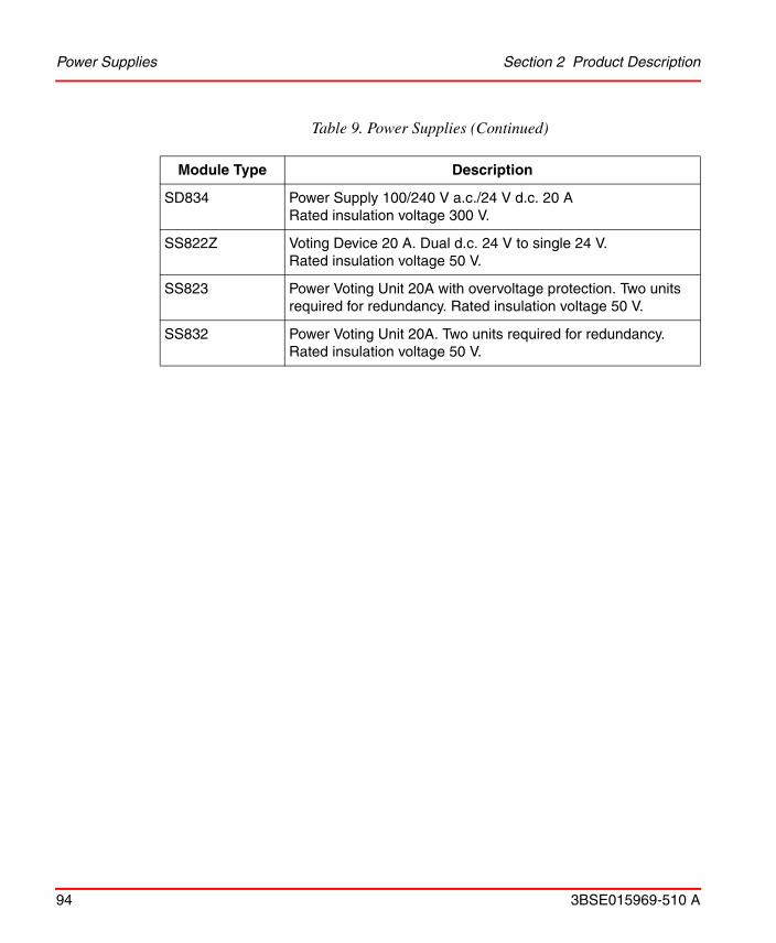
Power Supplies Section 2 Product Description
94 3BSE015969-510 A
SD834 Power Supply 100/240 V a.c./24 V d.c. 20 ARated insulation voltage 300 V.
SS822Z Voting Device 20 A. Dual d.c. 24 V to single 24 V.Rated insulation voltage 50 V.
SS823 Power Voting Unit 20A with overvoltage protection. Two units required for redundancy. Rated insulation voltage 50 V.
SS832 Power Voting Unit 20A. Two units required for redundancy. Rated insulation voltage 50 V.
Table 9. Power Supplies (Continued)
Module Type Description

Section 2 Product Description Power Supplies
3BSE015969-510 A 95
Figure 40. Power Supply Module SD831
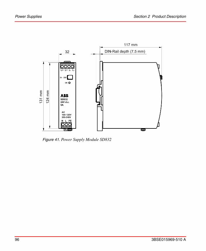
Power Supplies Section 2 Product Description
96 3BSE015969-510 A
Figure 41. Power Supply Module SD832

Section 2 Product Description Power Supplies
3BSE015969-510 A 97
Figure 42. Power Supply Module SD833

Power Supplies Section 2 Product Description
98 3BSE015969-510 A
Figure 43. Power Supply Module SD834

Section 2 Product Description Power Supplies
3BSE015969-510 A 99
Figure 44. Voting Unit SS823

Power Supplies Section 2 Product Description
100 3BSE015969-510 A
Figure 45. Voting Unit SS832
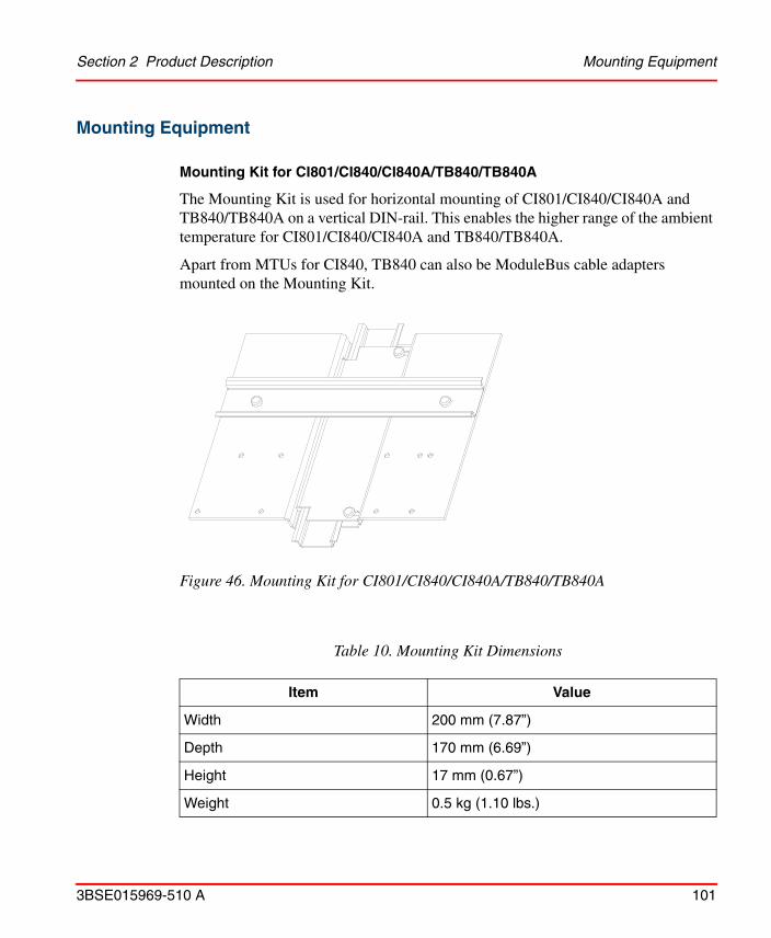
Section 2 Product Description Mounting Equipment
3BSE015969-510 A 101
Mounting Equipment
Mounting Kit for CI801/CI840/CI840A/TB840/TB840A
The Mounting Kit is used for horizontal mounting of CI801/CI840/CI840A and TB840/TB840A on a vertical DIN-rail. This enables the higher range of the ambient temperature for CI801/CI840/CI840A and TB840/TB840A.
Apart from MTUs for CI840, TB840 can also be ModuleBus cable adapters mounted on the Mounting Kit.
Figure 46. Mounting Kit for CI801/CI840/CI840A/TB840/TB840A
Table 10. Mounting Kit Dimensions
Item Value
Width 200 mm (7.87”)
Depth 170 mm (6.69”)
Height 17 mm (0.67”)
Weight 0.5 kg (1.10 lbs.)

Mounting Equipment Section 2 Product Description
102 3BSE015969-510 A
There are 9 different configuration alternatives for mounting of MTUs, see Figure 47.
Prefabricated Aluminium Profile
Prefabricated aluminium profile for mounting of S800 I/O modules in cabinets or other types of installations. The profile supports good mechanical stability and chassis ground connection.
There are aluminium profiles for horizontal 465 mm (19”), 592 mm (24”) or 719 mm (28.31”) mounting, see Figure 48.
Figure 47. Configurations for mounting of MTUs on the Mounting Kit
TU840/TU848 TU841/TU849TB845 TB805 TB845TU846 TB805TU847
TB846 TU846 TB845 TB806 TU847 TB805 TU807 TB805
TB806 CI801 TB805 CI801 TB805
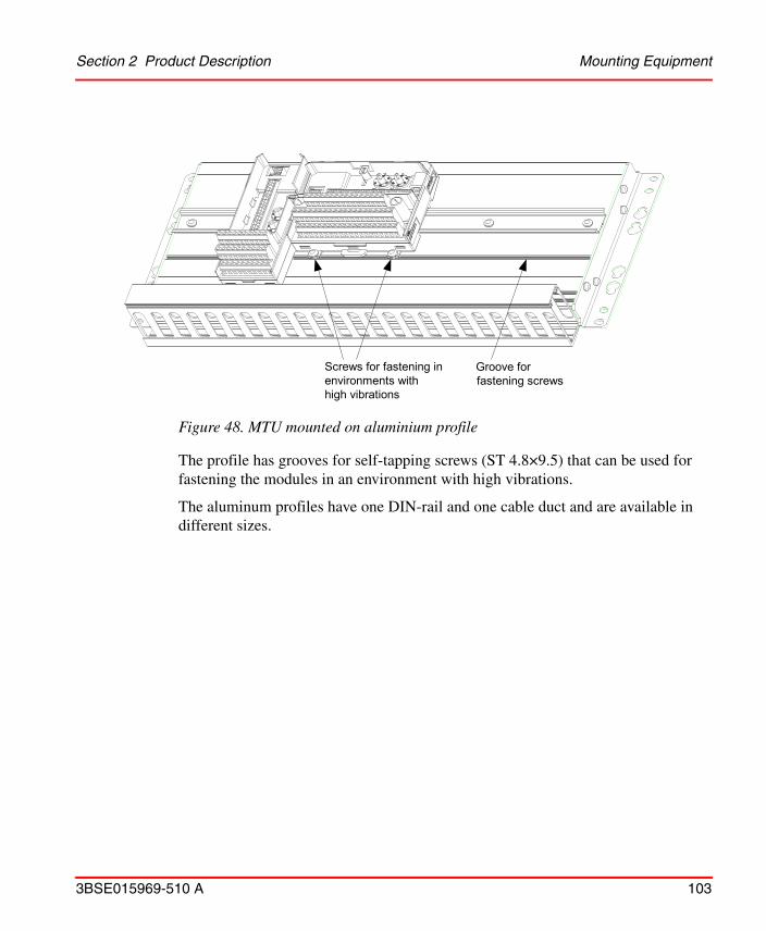
Section 2 Product Description Mounting Equipment
3BSE015969-510 A 103
The profile has grooves for self-tapping screws (ST 4.8×9.5) that can be used for fastening the modules in an environment with high vibrations.
The aluminum profiles have one DIN-rail and one cable duct and are available in different sizes.
Figure 48. MTU mounted on aluminium profile
Screws for fastening inenvironments withhigh vibrations
Groove forfastening screws
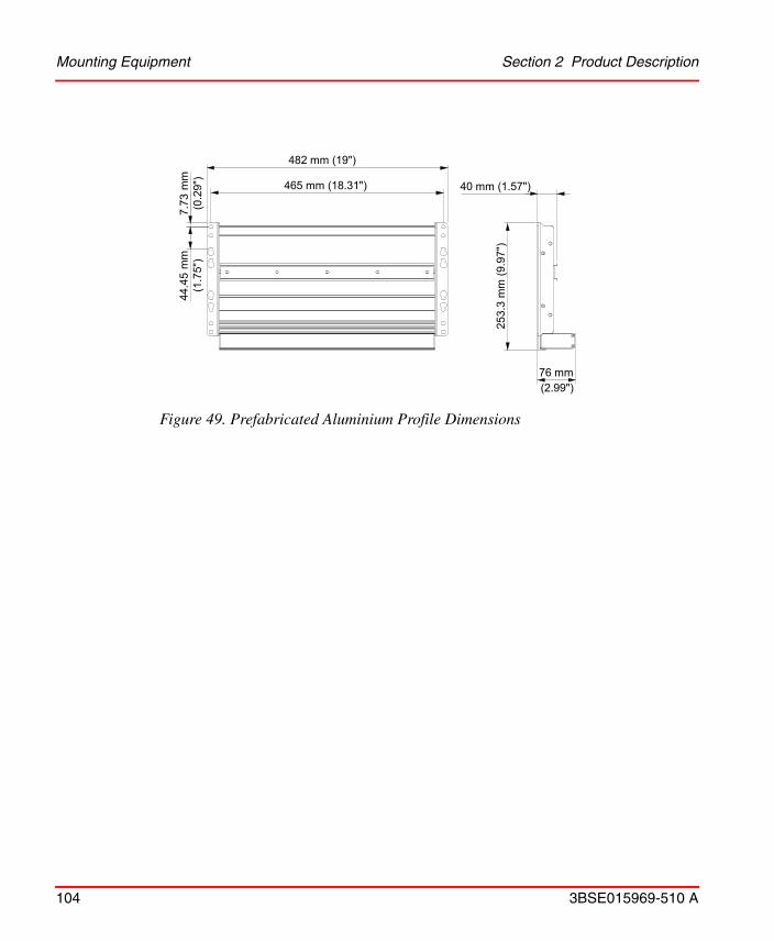
Mounting Equipment Section 2 Product Description
104 3BSE015969-510 A
Figure 49. Prefabricated Aluminium Profile Dimensions
482 mm (19")
465 mm (18.31")7.
73 m
m(0
.29"
)44
.45
mm
(1.7
5")
40 mm (1.57")
253.
3 m
m (
9.97
")
76 mm(2.99")

Section 2 Product Description G3 compliant modules
3BSE015969-510 A 105
G3 compliant modules
In general, all S800 units are G3 compliant (for exceptions, see Product Overview on page 24).
The G3 compliant units withstand more severe environmental conditions according to ISA-S71.04.
During transport, storage and installation special caution must be taken:
• Dividable connectors/terminals must not be left unconnected/open in G3 environment if they are intended to be used later.
• Modules must not be stored in G3 environment due to unprotected connectors/terminals, also valid for modules in packaging.
I/O Station Configurations
An I/O station can consist of one Base I/O cluster and up to seven I/O clusters. The Base I/O cluster consists of a FCI, single or redundant, and up to 12 I/O modules.
The I/O cluster consists of one ModuleBus Modem and up to 12 I/O modules. For I/O station with single FCI for PROFIBUS or AF100, and redundant FCI for AF100, see Figure 50. Both PROFIBUS and AF100 have non-redundant ModuleBus Extension.
For I/O station with redundant FCIs, and for PROFIBUS with non-redundant ModuleBus Extension, see Figure 51.
For I/O cluster connected to controller AC800M, via redundant ModuleBus Extension, see Figure 52. Redundant ModuleBus Extension can only be used together with AC800M.
Redundant I/O can only be configured in the base cluster.

I/O Station Configurations Section 2 Product Description
106 3BSE015969-510 A
Figure 50. Optical ModuleBus Extension from CI810, CI820
ModuleBus Modem TB820
CI810 FCI
Base I/O Cluster
I/O Cluster 1
I/O Cluster 2
I/O Cluster 3
Optical ModuleBus Port TB810
ModuleBus Modem TB820
Base I/O Cluster
I/O Cluster 1
I/O Cluster 2
I/O Cluster 3
Optical ModuleBus Port TB810
CI820 FCI
TB815InterconnectionUnit
TB 807 ModuleBus Terminator
TB 806 ModuleBus Cable Adaptor-In
Section 2 Product Description I/O Station Configurations
3BSE015969-510 A 107
Figure 51. Optical ModuleBus Extension from CI840
CI840
Base I/O Cluster
I/O Cluster 1
I/O Cluster 2
I/O Cluster 3
TB806/TB846
TB842 TU846/TU847
ModuleBusModemTB820
TB807
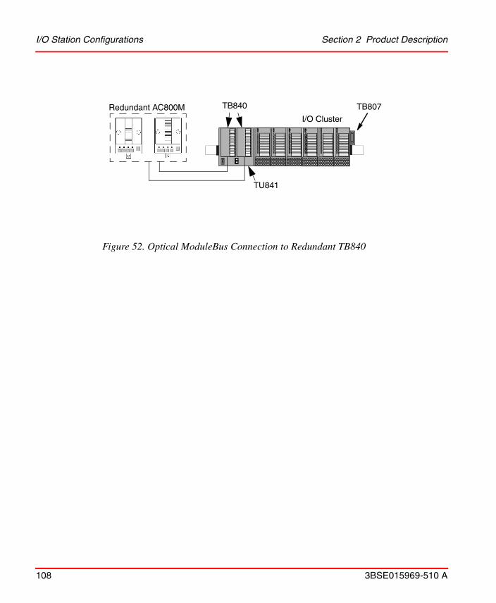
I/O Station Configurations Section 2 Product Description
108 3BSE015969-510 A
Figure 52. Optical ModuleBus Connection to Redundant TB840
I/O Cluster
TB840
TU841
TB807Redundant AC800M
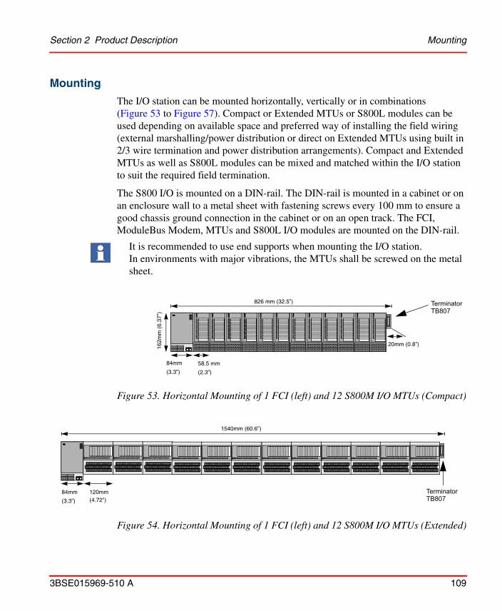
Section 2 Product Description Mounting
3BSE015969-510 A 109
Mounting
The I/O station can be mounted horizontally, vertically or in combinations (Figure 53 to Figure 57). Compact or Extended MTUs or S800L modules can be used depending on available space and preferred way of installing the field wiring (external marshalling/power distribution or direct on Extended MTUs using built in 2/3 wire termination and power distribution arrangements). Compact and Extended MTUs as well as S800L modules can be mixed and matched within the I/O station to suit the required field termination.
The S800 I/O is mounted on a DIN-rail. The DIN-rail is mounted in a cabinet or on an enclosure wall to a metal sheet with fastening screws every 100 mm to ensure a good chassis ground connection in the cabinet or on an open track. The FCI, ModuleBus Modem, MTUs and S800L I/O modules are mounted on the DIN-rail.
It is recommended to use end supports when mounting the I/O station. In environments with major vibrations, the MTUs shall be screwed on the metal sheet.
Figure 53. Horizontal Mounting of 1 FCI (left) and 12 S800M I/O MTUs (Compact)
Figure 54. Horizontal Mounting of 1 FCI (left) and 12 S800M I/O MTUs (Extended)
826 mm (32.5”)
84mm 58.5 mm
20mm (0.8”)162m
m (
6.37
”)
(3.3”) (2.3”)
TerminatorTB807
84mm 120mm
1540mm (60.6”)
(3.3”) (4.72”)
TerminatorTB807
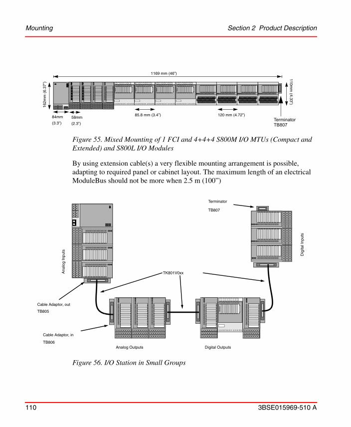
Mounting Section 2 Product Description
110 3BSE015969-510 A
By using extension cable(s) a very flexible mounting arrangement is possible, adapting to required panel or cabinet layout. The maximum length of an electrical ModuleBus should not be more when 2.5 m (100”)
Figure 55. Mixed Mounting of 1 FCI and 4+4+4 S800M I/O MTUs (Compact and Extended) and S800L I/O Modules
Figure 56. I/O Station in Small Groups
1169 mm (46”)
84mm 58mm85.8 mm (3.4”)
162m
m (
6.37
”)
110mm
(4.33”)
(3.3”) (2.3”)TerminatorTB807
1 2 3 4 5 6 7 8 9 11 1213141510 16
Sta
tus
S12345678910111213141516
1 2 3 4 5 6 7 8 9 11 1213141510 16
Sta
tus
S12345678910111213141516
1 2 3 4 5 6 7 8 9 11 1213141510 16
Sta
tus
S12345678910111213141516
1 2 3 4 5 6 7 8 9 11 1213141510 16
Sta
tus
S12345678910111213141516
120 mm (4.72”)
Cable Adaptor, out
TB805
Cable Adaptor, in
TB806
Terminator
TB807
Dig
ital I
nput
s
Ana
log
Inpu
ts
Analog Outputs Digital Outputs
TK801V0xx
1 2 3 4 5 6 7 8 9 11 12 13 14 1510 16
Sta
tus
S12345678910 1112131415 16

Section 2 Product Description Mounting
3BSE015969-510 A 111
In I.S. applications, modules with I.S. Interfaces MUST be mounted right most of the I/O station or as a separate group.
The installation must be performed by qualified personnel. It must comply with the relevant national/international standards (e.g. IEC 79-14, CEI 64-2, BS 5345 Pt. 4, DIN VDE 165) and in-line with the established installation rules and recommended practice (e.g. CEI 64-8, ANSI/ISA RP-12.6). The conformity of hazardous area field devices with the related system documentation must always be checked.
When using modules with I.S. Interfaces in non I.S.applications, the I.S. modules can be placed in any position following the same rules as non I.S. modules.

Mounting Section 2 Product Description
112 3BSE015969-510 A
Figure 57. Vertical Mounting of S800M I/O MTUs
796mm (31.3”)
84mm (3.3”)
58mm (2.3”)
20mm (0.8”)
162mm (6.37”)
84mm (3.3”)
120mm (4.72”)
1540mm (60.6”)
110mm (4.33”)
162mm (6.37”)
20mm (0.8”)
123mm (4.83”)*
* Measurement for TU847 and CI840
1579mm (62.2”)*
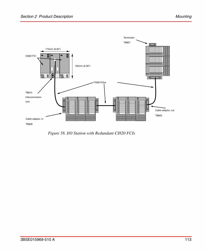
Section 2 Product Description Mounting
3BSE015969-510 A 113
Figure 58. I/O Station with Redundant CI820 FCIs
Cable adaptor, in
TB806
Terminator
TB807
TK801V0xx
CI820 FCI
TB815
Interconnection
Unit
Cable adaptor, out
TB805
162mm (6.36”)
174mm (6.84”)

Mounting Section 2 Product Description
114 3BSE015969-510 A
Figure 59. Maximum Layout of I/O Cluster with S800L
1143 mm (45”)
84 mm (3.3”)
20 mm
8485.8
22 mm
366.6 mm (14.4”)
821.4 mm
Bus CableLength = 300 mm
162
mm
110 mm
85.8 mm (3.4”)
(0.8”)
123 mm (4.83”)*
(0.87”)
(4.3”)
(32.3“)
(6.3
8”)
(11.8”)
85.8 mm
12
34
56
78
911
1213141510
16
Status S12345678910111213141516
12
34
56
78
911
1213141510
16
Status S12345678910111213141516
12
34
56
78
911
1213141510
16
Status S12345678910111213141516
12
34
56
78
911
1213141510
16
Status S12345678910111213141516
12
34
56
78
911
1213141510
16
Status S12345678910111213141516
12
34
56
78
911
1213141510
16
Status S12345678910111213141516
12
34
56
78
911
1213141510
16
Status S12345678910111213141516
12
34
56
78
911
1213141510
16
Status S12345678910111213141516
12
34
56
78
911
1213141510
16
Status S12345678910111213141516
123456789 11 1213141510 16
Sta
tus
S12345678910111213141516
123456789 11 1213141510 16
Sta
tus
S12345678910111213141516
123456789 11 1213141510 16
Sta
tus
S12345678910111213141516
12
34
56
78
911
1213141510
16
Status S12345678910111213141516
12
34
56
78
911
1213141510
16
Status S12345678910111213141516
12
34
56
78
911
1213141510
16
Status S12345678910111213141516
12
34
56
78
911
1213141510
16
Status S12345678910111213141516
12
34
56
78
911
1213141510
16
Status S12345678910111213141516
12
34
56
78
911
1213141510
16
Status S12345678910111213141516
12
34
56
78
911
1213141510
16
Status S12345678910111213141516
12
34
56
78
911
1213141510
16
Status S12345678910111213141516
12
34
56
78
911
1213141510
16
Status S12345678910111213141516
12
34
56
78
911
1213141510
16
Status S12345678910111213141516
12
34
56
78
911
1213141510
16
Status S12345678910111213141516
12
34
56
78
911
1213141510
16
Status S12345678910111213141516
20 mm
(0.8”)
22 mm
(0.87”)
(3.4”)
mm(inch)
* Measurements for TU847 and CI840
123*
405.6 mm (16”)*
1182 mm (46.5”)*

Section 2 Product Description Mounting
3BSE015969-510 A 115

Mounting Section 2 Product Description
116 3BSE015969-510 A

3BSE015969-510 A 117
Section 3 Technical Data and Performance
Directives
EMC Directive
All products, mentioned in this document, that bares the CE marking, meet the requirement of the EMC Directive EMCD 2004/108/EC. The following standards have been applied:• EN 61000-6-4 (2007) EMC, Emission• EN 61000-6-2 (2005) EMC, Immunity
Low Voltage Directive
All products, mentioned in this document, that bares the CE marking, meet the requirement of the Low Voltage Directive LVD 2006/95/EC. The following standard has been applied:• EN 61131-2 (2007) Clause 11, 12, 13 and 14.
ATEX directive
All products, mentioned in this document, that bares the Ex symbol, meet the requirement of the ATEX Directive ATEX 94/9/EC. For more information, see Certifications on page 169.
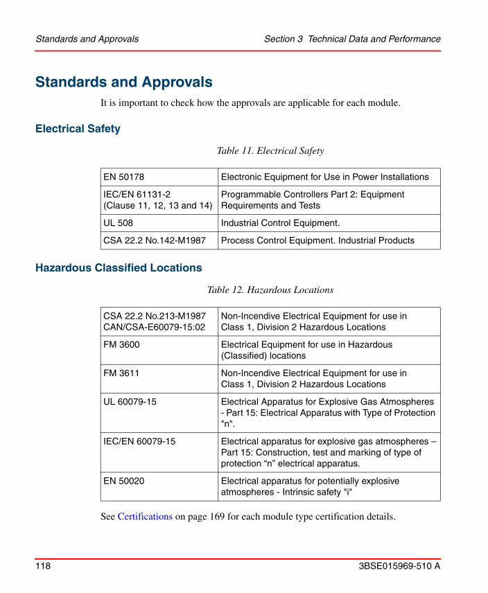
Standards and Approvals Section 3 Technical Data and Performance
118 3BSE015969-510 A
Standards and ApprovalsIt is important to check how the approvals are applicable for each module.
Electrical Safety
Hazardous Classified Locations
See Certifications on page 169 for each module type certification details.
Table 11. Electrical Safety
EN 50178 Electronic Equipment for Use in Power Installations
IEC/EN 61131-2 (Clause 11, 12, 13 and 14)
Programmable Controllers Part 2: Equipment Requirements and Tests
UL 508 Industrial Control Equipment.
CSA 22.2 No.142-M1987 Process Control Equipment. Industrial Products
Table 12. Hazardous Locations
CSA 22.2 No.213-M1987 CAN/CSA-E60079-15:02
Non-Incendive Electrical Equipment for use in Class 1, Division 2 Hazardous Locations
FM 3600 Electrical Equipment for use in Hazardous (Classified) locations
FM 3611 Non-Incendive Electrical Equipment for use in Class 1, Division 2 Hazardous Locations
UL 60079-15 Electrical Apparatus for Explosive Gas Atmospheres - Part 15: Electrical Apparatus with Type of Protection "n".
IEC/EN 60079-15 Electrical apparatus for explosive gas atmospheres –Part 15: Construction, test and marking of type of protection “n” electrical apparatus.
EN 50020 Electrical apparatus for potentially explosive atmospheres - Intrinsic safety "i"

Section 3 Technical Data and Performance CE-marking
3BSE015969-510 A 119
CE-marking
The S800 products fulfill the requirements of EU-directives 2004/108/EC "Electromagnetic Compatibility" (EMC Directive) and 2006/95/EC "Electrical Equipment Designed for Use between Certain Voltage Limits" (Low Voltage Directive). The declarations of conformity are available on request. See Certifications on page 169 for each module type certification details.
G3 Compliant
The G3 compliant modules fulfills the severity level in the standard ISA-S71.04 Environmental Conditions for Process Measurement and Control Systems: Airborne Contaminants.
The G3 compliant modules shall not be stored in more severe environment than G2 if the contacts are unconnected.
Transport and Storage ConditionsThe S800 modules should be transported and stored in their original packaging.
Table 13. S800 Storage Conditions
Condition Range Standard
Temperature -40 to +70°C IEC/EN 61131-2
Humidity RH = 5 to 95%, no condensation
Altitude -500 to +3000 m
Pollution degree Degree 2 IEC 60664-1
Corrosive atmosphere
< 1000 Angstrom copper corrosion over 28 days
ISA-71.04 Severity level G2
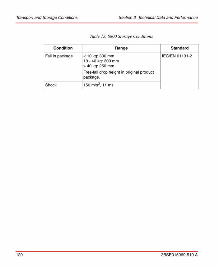
Transport and Storage Conditions Section 3 Technical Data and Performance
120 3BSE015969-510 A
Fall in package < 10 kg: 300 mm10 - 40 kg: 300 mm> 40 kg: 250 mm
Free-fall drop height in original product package.
IEC/EN 61131-2
Shock 150 m/s2, 11 ms
Table 13. S800 Storage Conditions
Condition Range Standard
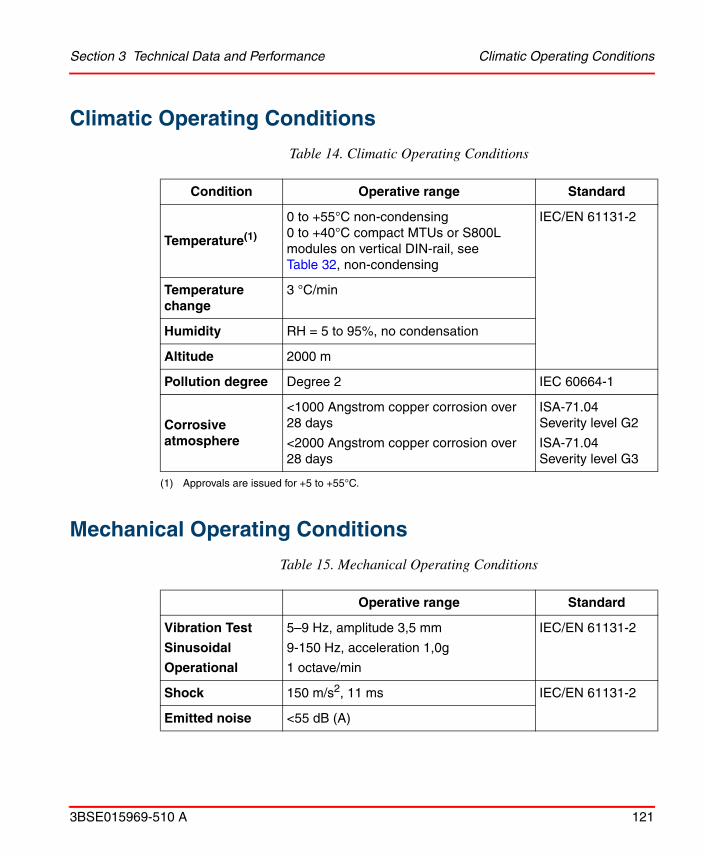
Section 3 Technical Data and Performance Climatic Operating Conditions
3BSE015969-510 A 121
Climatic Operating Conditions
Mechanical Operating Conditions
Table 14. Climatic Operating Conditions
Condition Operative range Standard
Temperature(1)
(1) Approvals are issued for +5 to +55°C.
0 to +55°C non-condensing0 to +40°C compact MTUs or S800L modules on vertical DIN-rail, see Table 32, non-condensing
IEC/EN 61131-2
Temperature change
3 °C/min
Humidity RH = 5 to 95%, no condensation
Altitude 2000 m
Pollution degree Degree 2 IEC 60664-1
Corrosive atmosphere
<1000 Angstrom copper corrosion over 28 days
<2000 Angstrom copper corrosion over 28 days
ISA-71.04 Severity level G2
ISA-71.04 Severity level G3
Table 15. Mechanical Operating Conditions
Operative range Standard
Vibration Test
Sinusoidal
Operational
5–9 Hz, amplitude 3,5 mm
9-150 Hz, acceleration 1,0g
1 octave/min
IEC/EN 61131-2
Shock 150 m/s2, 11 ms IEC/EN 61131-2
Emitted noise <55 dB (A)

EMC Section 3 Technical Data and Performance
122 3BSE015969-510 A
EMC
Table 16. Radiated Radio Frequency Emission IEC/EN 61000-6-4 (Class A), IEC/EN 61131-2
Radiated Radio Frequency Emission IEC/EN 61000-6-4 (Class A), IEC/EN 61131-2
Test LimitsGeneric
standards
30 MHz -230 MHz 40 dB (µV/m) quasi peak measured at 10m
EN/IEC 61000-6-4, EN/IEC 61131-2
230 MHz - 1000 MHz
47 dB (µV/m) quasi peak measured at 10m
Table 17. Conducted Radio Frequency Emission, AC mains port IEC 61000-6-4 (Class A), IEC/EN 61131-2
Conducted Radio Frequency Emission, AC mains port IEC 61000-6-4 (Class A), IEC/EN 61131-2
Test LimitsGeneric
standards
0,15 MHz -0,50 MHz
79 dB (µV/m) quasi peak66 dB (µV/m) average
EN/IEC 61000-6-4, EN/IEC 61131-2
0,50 MHz - 30 MHz 73 dB (µV) quasi peak60 dB (µV/m) average
Section 3 Technical Data and Performance EMC
3BSE015969-510 A 123
Table 18. Immunity IEC/EN 61000-6-2, IEC/EN 61131-2
Immunity IEC/EN 61000-6-2, IEC/EN 61131-2 Continuous...
Test SeverityGeneric
standards
Radiated RF field 80MHz – 1.0GHz, 10 V/m
1.4GHz – 2.0GHz, 3 V/m
2.0GHz – 2.7GHz, 1 V/m
EN/IEC 61000-6-2, EN/IEC 61131-2
Conducted RF field 0.15MHz-80MHz, 10V EN/IEC 61000-6-2, EN/IEC 61131-2
Table 19. Transients Immunity
Transients immunity
Electrostatic discharge
4 kV contact discharge 8 kV air discharge
IEC 61000-6-2, IEC 61131-2
Electrical fast transient/Burst
2 kV, AC/DC, process I/O AC1 kV, Process I/O DC, analog I/O and com
IEC 61000-6-2, IEC 61131-2
Surge 2 kV common mode, AC/DC power ports, process I/O AC1 kV differential mode, Process I/O DC, analog I/O and com
IEC 61000-6-2, IEC 61131-2
Overvoltage Categories Section 3 Technical Data and Performance
124 3BSE015969-510 A
Overvoltage Categories
AC mains power supplies are compliant with Overvoltage Category III networks (industrial mains). All I/O signals are overvoltage II compliant.
Equipment Class and Insulation Voltages
Equipment Class
The S800 equipment class is Class 1 according to IEC 60536. Class 1 means protection of electric shock by protective earth connection (PE). In this case this means a PE- connection must be made to the DIN-rail.
Insulation Voltage
All accessible ports on S800 modules are galvanically isolated from ground and system. For actual module isolation configuration, consult module data sheets.
Table 20. Overvoltage
Installation type Category Standards
Equipment permanently connected to low voltage mains
Overvoltage categories III IEC/EN 60664-1
Equipment not energized directly from the low voltage mains
Overvoltage categories II

Section 3 Technical Data and Performance Insulation Test Voltage
3BSE015969-510 A 125
Insulation Test Voltage
Type test, insulation test voltage
500 V a.c. or 700 V d.c. 1 minute for RIV 50V1 modules
2000 V a.c. 1 minute for RIV 250V modules
Routine Test, insulation test voltage
850 V d.c. 1 second for RIV 50V modules
2000 V a.c. 1 second for RIV 250V modules
1. Modules with a working voltage of less than 50 V have RIV 50 V. RIV 250 V applies to all modules having a working voltage greater than 50 V. It should be noted that insulation test voltage specifications, according to electrical safety standards, do not imply that permanent connection to circuits with voltages greater than the specified Rated Insulation Voltage is allowed. Connection to voltages higher than specified RIV violates electrical safety codes and may expose users to electric shock.
Capacity and Performance Section 3 Technical Data and Performance
126 3BSE015969-510 A
Capacity and Performance
Advant Fieldbus 100 Load
The bus load is calculated with different figures according to the bus length:
• for bus length max 2000 m (2200 yards), use Table 21
• for bus length max 8500 m (9300 yards), use Table 22
• for bus length max 15000 m (16400 yards), use Table 23.
To calculate the bus load in percent (AF100%load), at the required Cycle Time, the CI810/CI820 (FCI) loading per station and the I/O Module Type quantity times the per cent loading.
For bus load calculation, use the formula:
AF100%load = CI810/CI820load + S800 I/O Module 1load + S800 I/O Module nload +......
Calculation of load for AF100 with a length of max 2,000 m (2,200 yards)
Due to the organization of the Advant Fieldbus 100 scans, some constraints are imposed on the transmissions. To guarantee message transfer etc., at least 30% of the fieldbus load is reserved. The remaining load (up to 70%) can be used for S800 I/O station loading and other station loading.
Below is an example for an I/O station with one CI810 FCI, 2 AI810s, two AO810/AO810V2s, four DI810s and four DO810s using 128ms cycle time for AI and AO modules and 64ms for DI and DO modules:
AF100%load = 0.033% + (2 x 0.197%AI810) + (2 x 0.221%AO810/AO810V2)+ (4 x 0.138%DI810) + (4 x 0.146%DO810) = 2.005% Load
The calculated load of Advant Fieldbus 100 must be equal to or less than 70%.

Section 3 Technical Data and Performance Advant Fieldbus 100 Load
3BSE015969-510 A 127
Table 21. % of load on the Advant Fieldbus 100 by S800 I/O (up to 2000 m Bus Length)
Cycle Time (ms)
Module Type
AI801AI810AI890AI895
AI820AI830
AI830AAI835
AO801AO810
AO810V2AO890AO895
AO820
DI801, DI802DI803, DI810DI811, DI814DI820, DI821DI830, DI831DI885, DI890
DO801(1), DO802DO810(1), DO814(1), DO815(1), DO820(1), DO821(1), DO890(1)
(1) Readbacks increase the load depending on the cyclicity and with the same amount as the net load at the cycle time. For Master the cycle time is 1024 which gives 0.009% more load. For MOD the cycle time is configurable.
DP820(2)
INSCANT
(2) Total load = (load generated by INSCANT) + (load generated by OUTSCANT)The total load if INSCANT is 32 ms and OUTSCANT is 64 ms is:Total load = 0.788 + 0.244 = 1.032%
DP820(2)
OUT-
SCANT
1 25.2% 15.6% 25.3% 25.23% 15.62% 8.8% 8.8% 25.2% 15.6%
2 12.6% 7.8% 12.6% 12.63% 7.815% 4.4% 4.4% 12.6% 7.8%
4 6.3% 3.9% 6.3% 6.325% 3.915% 2.2% 2.2% 6.3% 3.9%
8 3.15% 1.95% 3.15% 3.175% 1.965% 1.1% 1.1% 3.15% 1.95%
16 1.575% 0.975% 1.575% 1.6% 0.99% 0.55% 0.55% 1.575% 0.975%
32 0.788% 0.488% 0.788% 0.812% 0.503% 0.275% 0.275% 0.788% 0.488%
64 0.394% 0.244% 0.394% 0.418% 0.259% 0.138% 0.138% 0.394% 0.244%
128 0.197% 0.122% 0.197% 0.221% 0.137% 0.069% 0.069% 0.197% 0.122%
256 0.098% 0.061% 0.098% 0.123% 0.076% 0.034% 0.034% 0.098% 0.061%
512 0.049% 0.03% 0.049% 0.074% 0.046% 0.017% 0.017% 0.049% 0.030%
1024 0.025% 0.015% 0.025% 0.049% 0.03% 0.009% 0.009% 0.025% 0.015%
2048 0.012% 0.008% 0.012% 0.037% 0.023% 0.004% 0.004% 0.012% 0.008%
4096 0.006% 0.004% 0.006% 0.031% 0.019% 0.002% 0.002% 0.006% 0.004%
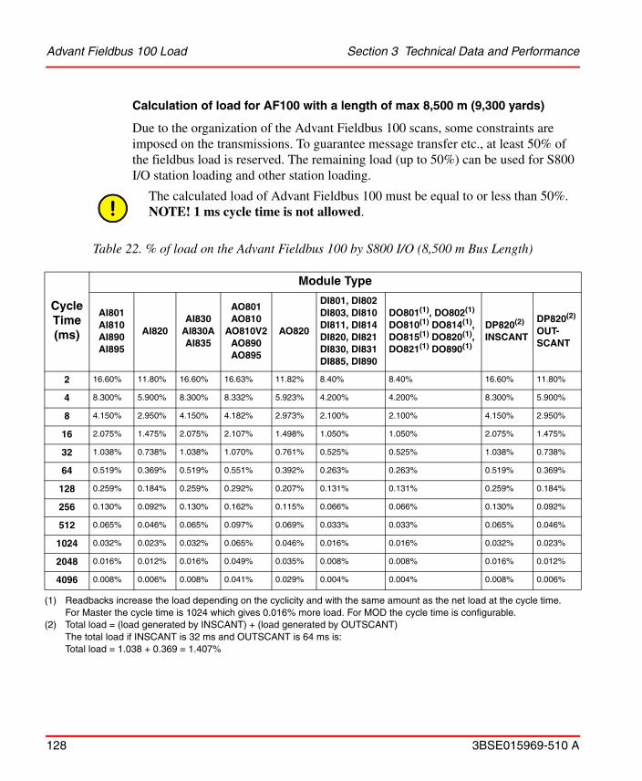
Advant Fieldbus 100 Load Section 3 Technical Data and Performance
128 3BSE015969-510 A
Calculation of load for AF100 with a length of max 8,500 m (9,300 yards)
Due to the organization of the Advant Fieldbus 100 scans, some constraints are imposed on the transmissions. To guarantee message transfer etc., at least 50% of the fieldbus load is reserved. The remaining load (up to 50%) can be used for S800 I/O station loading and other station loading.
The calculated load of Advant Fieldbus 100 must be equal to or less than 50%.NOTE! 1 ms cycle time is not allowed.
Table 22. % of load on the Advant Fieldbus 100 by S800 I/O (8,500 m Bus Length)
Cycle Time (ms)
Module Type
AI801AI810AI890AI895
AI820AI830
AI830AAI835
AO801AO810
AO810V2AO890AO895
AO820
DI801, DI802DI803, DI810DI811, DI814 DI820, DI821 DI830, DI831 DI885, DI890
DO801(1), DO802(1)
DO810(1) DO814(1), DO815(1) DO820(1), DO821(1) DO890(1)
(1) Readbacks increase the load depending on the cyclicity and with the same amount as the net load at the cycle time. For Master the cycle time is 1024 which gives 0.016% more load. For MOD the cycle time is configurable.
DP820(2)
INSCANT
(2) Total load = (load generated by INSCANT) + (load generated by OUTSCANT)The total load if INSCANT is 32 ms and OUTSCANT is 64 ms is:Total load = 1.038 + 0.369 = 1.407%
DP820(2)
OUT-SCANT
2 16.60% 11.80% 16.60% 16.63% 11.82% 8.40% 8.40% 16.60% 11.80%
4 8.300% 5.900% 8.300% 8.332% 5.923% 4.200% 4.200% 8.300% 5.900%
8 4.150% 2.950% 4.150% 4.182% 2.973% 2.100% 2.100% 4.150% 2.950%
16 2.075% 1.475% 2.075% 2.107% 1.498% 1.050% 1.050% 2.075% 1.475%
32 1.038% 0.738% 1.038% 1.070% 0.761% 0.525% 0.525% 1.038% 0.738%
64 0.519% 0.369% 0.519% 0.551% 0.392% 0.263% 0.263% 0.519% 0.369%
128 0.259% 0.184% 0.259% 0.292% 0.207% 0.131% 0.131% 0.259% 0.184%
256 0.130% 0.092% 0.130% 0.162% 0.115% 0.066% 0.066% 0.130% 0.092%
512 0.065% 0.046% 0.065% 0.097% 0.069% 0.033% 0.033% 0.065% 0.046%
1024 0.032% 0.023% 0.032% 0.065% 0.046% 0.016% 0.016% 0.032% 0.023%
2048 0.016% 0.012% 0.016% 0.049% 0.035% 0.008% 0.008% 0.016% 0.012%
4096 0.008% 0.006% 0.008% 0.041% 0.029% 0.004% 0.004% 0.008% 0.006%

Section 3 Technical Data and Performance Advant Fieldbus 100 Load
3BSE015969-510 A 129
Calculation of load for AF100 with a length of max 15,000 m (16,400 yards)
Due to the organization of the Advant Fieldbus 100 scans, some constraints are imposed on the transmissions. To guarantee message transfer etc., at least 50% of the fieldbus load is reserved. The remaining load (up to 50%) can be used for S800 I/O station loading and other station loading.
The calculated load of Advant Fieldbus 100 must be equal to or less than 50%.NOTE! 1 ms cycle time is not allowed.
Table 23. % of load on the Advant Fieldbus 100 by S800 I/O (15,000 m Bus Length)
Cycle Time (ms)
Module Type
AI801 AI810 AI890AI895
AI820AI830
AI830AAI835
AO801AO810
AO810V2AO890AO895
AO820
DI801, DI802DI803, DI810 DI811, DI814 DI820, DI821 DI830, DI831 DI885, DI890
DO801(1), DO802DO810(1), DO814(1), DO815(1), DO820(1), DO821(1), DO890(1)
(1) Readbacks increase the load depending on the cyclicity and with the same amount as the net load at the cycle time. For Master the cycle time is 1024 which gives 0.009% more load. For MOD the cycle time is configurable.
DP820(2)
INSCANT
(2) Total load = (load generated by INSCANT) + (load generated by OUTSCANT)The total load if INSCANT is 32 ms and OUTSCANT is 64 ms is:Total load = 1.288 + 0.494 = 1.782%
DP820(2)
OUT-SCANT
2 20.60% 15.80% 20.60% 20.64% 15.83% 12.40% 12.40% 20.60% 15.80%
4 10.30% 7.900% 10.30% 10.34% 7.931% 6.200% 6.200% 10.30% 7.900%
8 5.150% 3.950% 5.150% 5.190% 3.981% 3.100% 3.100% 5.150% 3.950%
16 2.575% 1.975% 2.575% 2.615% 2.006% 1.550% 1.550% 2.575% 1.975%
32 1.288% 0.988% 1.288% 1.328% 1.018% 0.775% 0.775% 1.288% 0.988%
64 0.644% 0.494% 0.644% 0.684% 0.525% 0.388% 0.388% 0.644% 0.494%
128 0.322% 0.247% 0.322% 0.362% 0.278% 0.194% 0.194% 0.322% 0.247%
256 0.161% 0.123% 0.161% 0.201% 0.154% 0.097% 0.097% 0.161% 0.123%
512 0.080% 0.062% 0.080% 0.121% 0.093% 0.048% 0.048% 0.080% 0.062%
1024 0.040% 0.031% 0.040% 0.080% 0.062% 0.024% 0.024% 0.040% 0.031%
2048 0.020% 0.015% 0.020% 0.060% 0.046% 0.012% 0.012% 0.020% 0.015%
4096 0.010% 0.008% 0.010% 0.050% 0.039% 0.006% 0.006% 0.010% 0.008%

PROFIBUS CI801 Section 3 Technical Data and Performance
130 3BSE015969-510 A
PROFIBUS CI801
Number of S800 I/O Stations
Maximum number of S800 I/O stations per bus: 99 stations
Supported communication speeds: 9.6 kbit/s to 12 Mbit/s
Maximum number of S800 I/O stations per Profibus bus segment: 32 stations.
Maximum number of S800 I/O modules in a station: 24 modules
Maximum number of S800 I/O modules per cluster: 12 modules
It is not allowed to physically install more than 12 MTUs and/or S800L modules in a cluster.
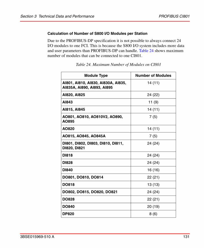
Section 3 Technical Data and Performance PROFIBUS CI801
3BSE015969-510 A 131
Calculation of Number of S800 I/O Modules per Station
Due to the PROFIBUS-DP specification it is not possible to always connect 24 I/O modules to one FCI. This is because the S800 I/O system includes more data and user parameters than PROFIBUS-DP can handle. Table 24 shows maximum number of modules that can be connected to one CI801.
Table 24. Maximum Number of Modules on CI801
Module Type Number of Modules
AI801, AI810, AI830, AI830A, AI835, AI835A, AI890, AI893, AI895
14 (11)
AI820, AI825 24 (22)
AI843 11 (9)
AI815, AI845 14 (11)
AO801, AO810, AO810V2, AO890, AO895
7 (5)
AO820 14 (11)
AO815, AO845, AO845A 7 (5)
DI801, DI802, DI803, DI810, DI811, DI820, DI821
24 (24)
DI818 24 (24)
DI828 24 (24)
DI840 16 (16)
DO801, DO810, DO814 22 (21)
DO818 13 (13)
DO802, DO815, DO820, DO821 24 (24)
DO828 22 (21)
DO840 20 (19)
DP820 8 (6)

PROFIBUS CI801 Section 3 Technical Data and Performance
132 3BSE015969-510 A
The values in brackets are in Extended HART mode and HCIR.
In order to find out if a given configuration of analog and digital modules can be used, the following method should be used:
• Fill in number of modules in Table 25.
• Calculate the sum in the three columns:
– Sum User Parameters
– Sum Input Bytes
– Sum Output Bytes
• Calculate the three total sums for:
– ParamSize
– InSize
– OutSize.
• Check that:
– ParamSize is less than or equal to 221 (220 if HCIR is used)
– InSize is less than or equal to 239 in normal mode, 199 in Extended HART mode
– OutSize is less than or equal to 112 in normal mode, 90 in Extended HART mode
If any of these three values is too high then the configuration can not be used.
DP840 7 (5)
Standard Drives 9 (7)
Table 24. Maximum Number of Modules on CI801 (Continued)
Module Type Number of Modules

Section 3 Technical Data and Performance PROFIBUS CI801
3BSE015969-510 A 133
Table 25. Calculation of Number of Modules on CI801
Module Type
User Parameters
Input Bytes
Output Bytes
Number of
Modules
Sum User Para-
meters
Sum Input Bytes
Sum Output Bytes
AI801 13 17 0
AI810 13 17 0
AI820 9 9 0
AI825 9 9 0
AI830/AI830A
12 17 0
AI835 15 17 0
AI835A 16 17 2
AI843 16 20 2
AI815, AI845
13 17 0
AI890 13 17 0
AI893 15 17 0
AI895 13 17 0
AO801 17 1 16
AO810/AO810V2
17 1 16
AO820 11 1 8
AO815, AO845/AO845A
18 1 16
AO890 17 1 16
AO895 17 1 16
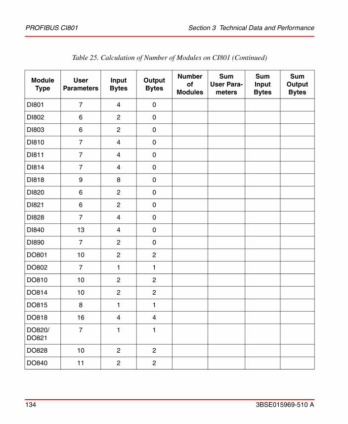
PROFIBUS CI801 Section 3 Technical Data and Performance
134 3BSE015969-510 A
DI801 7 4 0
DI802 6 2 0
DI803 6 2 0
DI810 7 4 0
DI811 7 4 0
DI814 7 4 0
DI818 9 8 0
DI820 6 2 0
DI821 6 2 0
DI828 7 4 0
DI840 13 4 0
DI890 7 2 0
DO801 10 2 2
DO802 7 1 1
DO810 10 2 2
DO814 10 2 2
DO815 8 1 1
DO818 16 4 4
DO820/DO821
7 1 1
DO828 10 2 2
DO840 11 2 2
Table 25. Calculation of Number of Modules on CI801 (Continued)
Module Type
User Parameters
Input Bytes
Output Bytes
Number of
Modules
Sum User Para-
meters
Sum Input Bytes
Sum Output Bytes
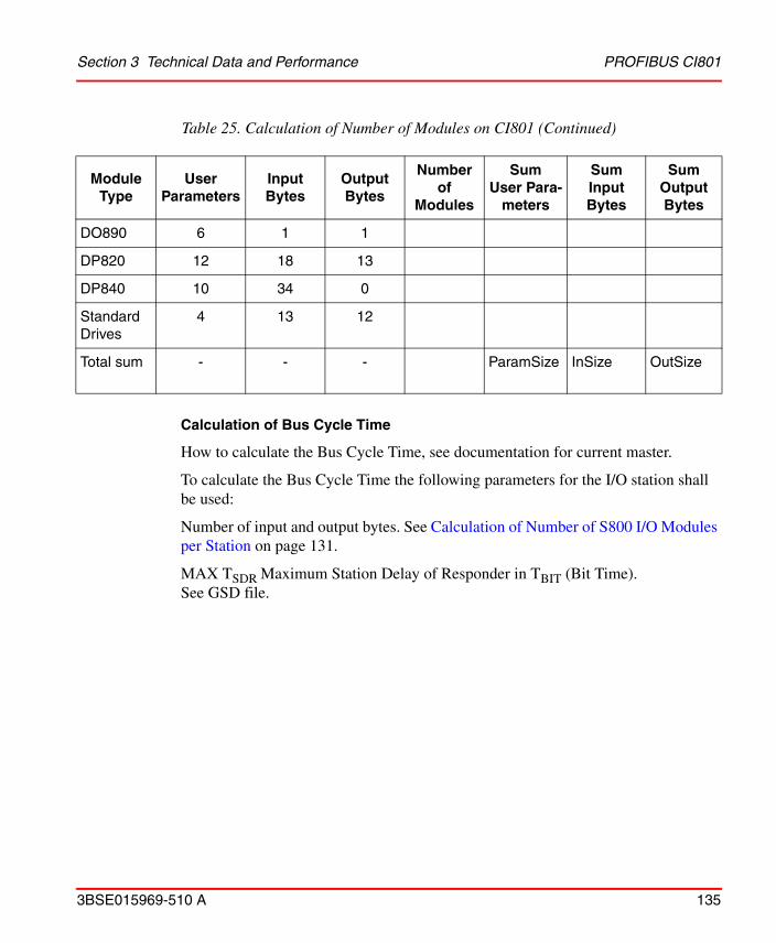
Section 3 Technical Data and Performance PROFIBUS CI801
3BSE015969-510 A 135
Calculation of Bus Cycle Time
How to calculate the Bus Cycle Time, see documentation for current master.
To calculate the Bus Cycle Time the following parameters for the I/O station shall be used:
Number of input and output bytes. See Calculation of Number of S800 I/O Modules per Station on page 131.
MAX TSDR Maximum Station Delay of Responder in TBIT (Bit Time). See GSD file.
DO890 6 1 1
DP820 12 18 13
DP840 10 34 0
StandardDrives
4 13 12
Total sum - - - ParamSize InSize OutSize
Table 25. Calculation of Number of Modules on CI801 (Continued)
Module Type
User Parameters
Input Bytes
Output Bytes
Number of
Modules
Sum User Para-
meters
Sum Input Bytes
Sum Output Bytes

PROFIBUS CI840 Section 3 Technical Data and Performance
136 3BSE015969-510 A
PROFIBUS CI840
Number of S800 I/O Stations
Maximum number of S800 I/O stations per bus:
• Redundant CI840: 62 stations.
• Single CI840: 99 stations
Supported communication speeds: 93.75 kbit/s to 12 Mbit/s
Maximum number of S800 I/O stations per PROFIBUS segment:
• Communication speed 12 Mbit: 20 stations.
• Communication speed 1,5 Mbit: 32 stations.
Maximum number of S800 I/O modules in a station: 24 modules
Maximum number of S800 I/O modules per cluster: 12 modules
Switch over time at failure in a redundant CI840 configuration is typical <100 ms and maximum 150 ms.
The 12 modules per cluster can either be 12 single I/O modules or 6 pairs of redundant I/O modules. Redundant I/O modules can only be mounted on the base cluster. It is not allowed to mix single and redundant I/O modules within a cluster. It is not allowed to physically install more than 12 single MTUs and/or S800L modules in a single cluster. It is also not allowed to physically install more than 6 redundant MTUs in a redundant cluster.
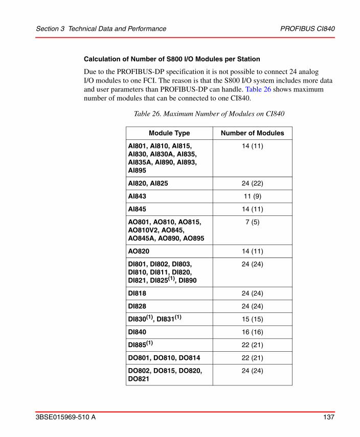
Section 3 Technical Data and Performance PROFIBUS CI840
3BSE015969-510 A 137
Calculation of Number of S800 I/O Modules per Station
Due to the PROFIBUS-DP specification it is not possible to connect 24 analog I/O modules to one FCI. The reason is that the S800 I/O system includes more data and user parameters than PROFIBUS-DP can handle. Table 26 shows maximum number of modules that can be connected to one CI840.
Table 26. Maximum Number of Modules on CI840
Module Type Number of Modules
AI801, AI810, AI815, AI830, AI830A, AI835, AI835A, AI890, AI893, AI895
14 (11)
AI820, AI825 24 (22)
AI843 11 (9)
AI845 14 (11)
AO801, AO810, AO815, AO810V2, AO845, AO845A, AO890, AO895
7 (5)
AO820 14 (11)
DI801, DI802, DI803, DI810, DI811, DI820, DI821, DI825(1), DI890
24 (24)
DI818 24 (24)
DI828 24 (24)
DI830(1), DI831(1) 15 (15)
DI840 16 (16)
DI885(1) 22 (21)
DO801, DO810, DO814 22 (21)
DO802, DO815, DO820, DO821
24 (24)
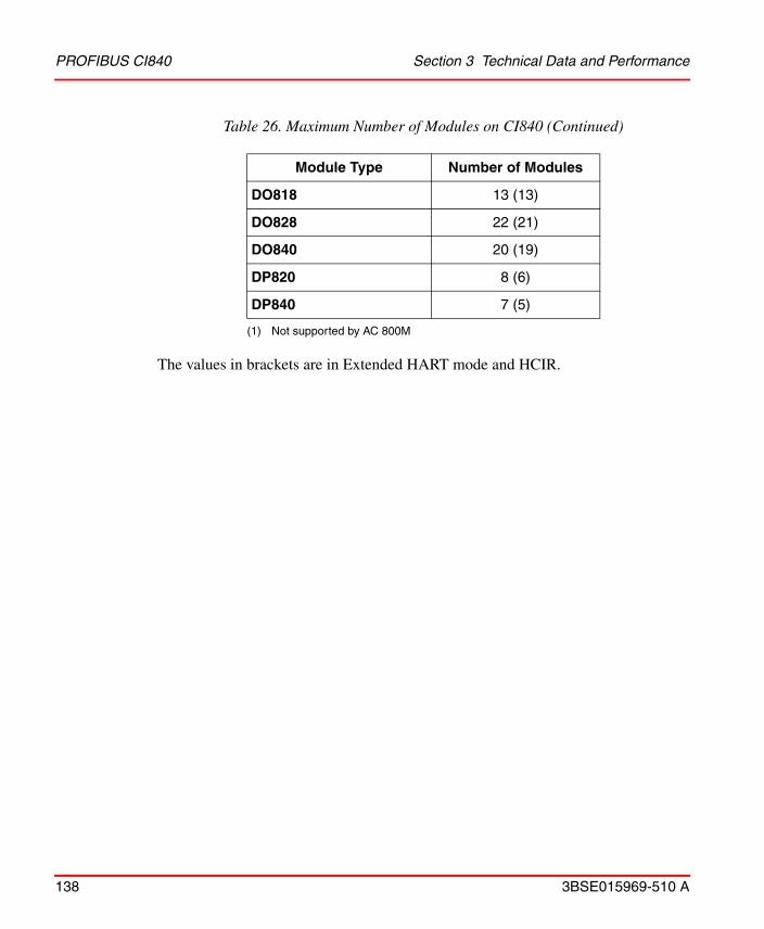
PROFIBUS CI840 Section 3 Technical Data and Performance
138 3BSE015969-510 A
The values in brackets are in Extended HART mode and HCIR.
DO818 13 (13)
DO828 22 (21)
DO840 20 (19)
DP820 8 (6)
DP840 7 (5)
(1) Not supported by AC 800M
Table 26. Maximum Number of Modules on CI840 (Continued)
Module Type Number of Modules

Section 3 Technical Data and Performance PROFIBUS CI840
3BSE015969-510 A 139
In order to find out if a given configuration of analog and digital modules can be used, the following method should be used:
• Fill in number of modules in Table 27.
• Calculate the sum in the three columns:
– Sum User Parameters
– Sum Input Bytes
– Sum Output Bytes
• Calculate the three total sums for:
– ParamSize
– InSize
– OutSize.
• Check that:
– ParamSize is less than or equal to 221 (220 if HCIR is used)
– InSize is less than or equal to 239 in normal mode, 199 in Extended HART mode
– OutSize is less than or equal to 112 in normal mode, 90 in Extended HART mode
If any of these three values is too high then the configuration can not be used.

PROFIBUS CI840 Section 3 Technical Data and Performance
140 3BSE015969-510 A
Table 27. Calculation of Number of Modules on CI840
Module Type
User Parameters
Input Bytes
Output Bytes
Number of
Modules
Sum User Para-
meters
Sum Input Bytes
Sum Output Bytes
AI801 13 17 0
AI810 13 17 0
AI820 9 9 0
AI825 9 9 0
AI830/AI830A
12 17 0
AI835 15 17 0
AI835A 16 17 2
AI843 16 20 2
AI845/AI815
13 17 0
AI890 13 17 0
AI893 15 17 0
AI895 13 17 0
AO801 17 1 16
AO810/AO810V2
17 1 16
AO820 11 1 8
AO815/AO845/AO845A
18 1 16
AO890 17 1 16
AO895 17 1 16

Section 3 Technical Data and Performance PROFIBUS CI840
3BSE015969-510 A 141
DI801 7 4 0
DI802 6 2 0
DI803 6 2 0
DI810 7 4 0
DI811 7 4 0
DI814 7 4 0
DI818 9 8 0
DI820 6 2 0
DI821 6 2 0
DI828 7 4 0
DI825(1) 9 2 0
DI830(1) 14 4 0
DI831(1) 14 4 0
DI840 13 4 -
DI885(1) 10 2 0
DI890 7 2 0
DO801 10 2 2
DO802 7 1 1
DO810 10 2 2
DO814 10 2 2
DO815 8 1 1
DO818 16 4 4
Table 27. Calculation of Number of Modules on CI840 (Continued)
Module Type
User Parameters
Input Bytes
Output Bytes
Number of
Modules
Sum User Para-
meters
Sum Input Bytes
Sum Output Bytes
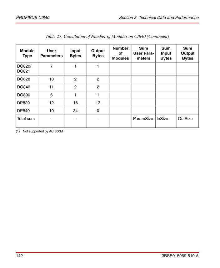
PROFIBUS CI840 Section 3 Technical Data and Performance
142 3BSE015969-510 A
DO820/DO821
7 1 1
DO828 10 2 2
DO840 11 2 2
DO890 6 1 1
DP820 12 18 13
DP840 10 34 0
Total sum - - - ParamSize InSize OutSize
(1) Not supported by AC 800M
Table 27. Calculation of Number of Modules on CI840 (Continued)
Module Type
User Parameters
Input Bytes
Output Bytes
Number of
Modules
Sum User Para-
meters
Sum Input Bytes
Sum Output Bytes

Section 3 Technical Data and Performance S800 I/O Station Data Scanning
3BSE015969-510 A 143
Calculation of Bus Cycle Time
How to calculate the Bus Cycle Time, see documentation for current master.
To calculate the Bus Cycle Time the following parameters for the I/O station shall be used:
Number of input and output bytes.
MAX TSDR Maximum Station Delay of Responder in TBIT (Bit Time). See GSD file.
S800 I/O Station Data Scanning
The ModuleBus data is scanned (read or written) cyclically, depending on the I/O module configuration. To calculate the I/O scan cycle time in the FCI do as follows:
Totalize (number of module type x) * (used execution time for type x) (see Table 28) if the value is a multiple of 2, add 2 to the value. Otherwise increase the total value to the nearest higher multiple of 2 to get the I/O scan cycle time.
If CI810A or C1810B is used, the scan cycle time is increased by 25% and for CI820 it is increased by 50%. If the value is a multiple of 2, add 2 to the value. Otherwise increase the value to the nearest higher multiple of 2, to get the I/O cycle time.
Table 28. I/O Scan Cycle Time in the FCI
Module Type
Execution Time Used in ms
CI801CI810, CI820
CI840
Single I/ORedundant
I/O pair
AI801, AI810, AI890, AI895 3.00 3.00 3.00 -
AI820 1.50 1.50 1.50 -
AI825 1.50 - 1.50 -
AI830, AI830A, AI835, AI835A 0.40 0.40 0.40 -
AI893 0.40 - 0.40 -

S800 I/O Station Data Scanning Section 3 Technical Data and Performance
144 3BSE015969-510 A
AI843 0.40 - 0.40 0.80
AI815, AI845 3.00 - 3.00 6.00
AO801, AO810, AO810V2, AO890, AO895
1.20 1.20 1.20 -
AO820 0.60 0.60 0.60 -
AO815, AO845, AO845A 1.20 - 1.20 2.40
DI801, DI810, DI811, DI814, DI820, DI821, DI890
0.43 0.43 0.50 -
DI818 0.86 - 1.0 -
DI802, DI803, DI828 0.43 - 0.50 -
DI840 0.43 - 0.50 1.00
DI830, DI831, DI885 - 0.43 - -
DO801, DO810, DO814, DO815, DO820, DO82
0.43 0.43 0.50 -
DO818 0.86 - 1.0 -
DO802, DO828 0.43 - 0.50 -
DO840 0.43 - 0.50 1.00
DO890 0.43 0.43 0.50 -
DP820 1.72 1.72 2.09 -
DP840 3.00 - 3.00 6.00
Engineered drives - 1.72 - -
Table 28. I/O Scan Cycle Time in the FCI (Continued)
Module Type
Execution Time Used in ms
CI801CI810, CI820
CI840
Single I/ORedundant
I/O pair
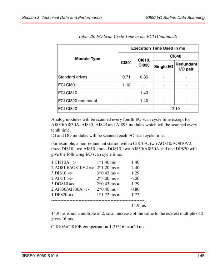
Section 3 Technical Data and Performance S800 I/O Station Data Scanning
3BSE015969-510 A 145
Analog modules will be scanned every fourth I/O scan cycle time except for AI830/AI830A, AI835, AI843 and AI893 modules which will be scanned every tenth time.DI and DO modules will be scanned each I/O scan cycle time.
For example, a non-redundant station with a CI810A, two AO810/AO810V2, three DI810, two AI810, three DO810, two AI830/AI830A and one DP820 will give the following I/O scan cycle time:
1 CI810A => 1*1.40 ms = 1.402 AO810/AO810V2 => 2*1.20 ms = 2.403 DI810 => 3*0.43 ms = 1.292 AI810 => 2*3.00 ms = 6.003 DO810 => 2*0.43 ms = 1.292 AI830/AI830A => 2*0.40 ms = 0.801 DP820 => 1*1.72 ms = 1.72-------------------------------------------------------------
14.9 ms
14.9 ms is not a multiple of 2, so an increase of the value to the nearest multiple of 2 gives 16 ms.
CI810A/CI810B compensation 1.25*16 ms=20 ms.
Standard drives 0.71 0.86 - -
FCI CI801 1.18 - - -
FCI CI810 - 1.40 - -
FCI CI820 redundant - 1.40 - -
FCI CI840 - - 2.10
Table 28. I/O Scan Cycle Time in the FCI (Continued)
Module Type
Execution Time Used in ms
CI801CI810, CI820
CI840
Single I/ORedundant
I/O pair

S800 I/O Station Data Scanning Section 3 Technical Data and Performance
146 3BSE015969-510 A
20 ms is a multiple of 2, so add 2 to the value 20. 20+2=22.
Section 3 Technical Data and Performance S800 I/O Station Data Scanning
3BSE015969-510 A 147
That will give an I/O scan cycle time of 22 ms between the FCI and its I/O modules. This means that the DIs and DOs will be scanned every 22 ms, the AI810s and the AO810/AO810V2 every (4*22 ms) 88ms and the AI830/AI830A every (10*22 ms) 220 ms.
For example, a redundant station with CI840, two AI810, one AO810/AO810V2, two DI810, two DO820 and one AI830/AI830A will give the following I/O scan cycle time:
2 AI810 => 2*3.00 ms = 6.00 ms1 AO810/AO810V2 => 1*1.20 ms = 1.20 ms2 DI810 => 2*0.50 ms = 1.00 ms2 DO810 => 2*0.50 ms = 1.00 ms1 AI830/AI830A => 1*0.40 ms = 0.40 ms1 CI840 => 1*2.10 ms = 2.10 ms------------------------------------------------------
11.7 ms
11.7 ms is not a multiple of 2, so increase of the value to the nearest multiple of 2 gives 12 ms.
That will give an I/O scan cycle time of 12 ms between the FCI and its I/O modules. This means that the DIs, DOs, DPs and Standard Drives will be scanned every 12 ms, the AIs and AOs every (4*12 ms) 48 ms and the AI830/AI830A, AI835, AI843 and AI893 every (10*12 ms) 120 ms.
Minimum I/O scan cycle time = 4 ms single FCI (CI810) with firmware 1.0 to 1.2Minimum I/O scan cycle time = 6 ms redundant FCI (CI820) with firmware 1.3 or later.
Minimum I/O scan cycle time = 4 ms.
Calculation of Maximum Distance of an Optical ModuleBus Configuration Section 3 Technical Data
148 3BSE015969-510 A
Calculation of Maximum Distance of an Optical ModuleBus Configuration
Calculation of Maximum Fibre length for TB825
The maximum signal delay should be calculated in the configuration using Optical ModuleBus Media Converter. This is calculated using the signal path from the controller to the point in the configuration that has the longest delay. The maximum delay in an optical ModuleBus configuration must be 100µs (less than 250µs for S800 I/O HI).
The delay values in Table 29 can be used to calculate the maximum delay in an optical ModuleBus configuration.
Table 29. Delay Values Optical ModuleBus Components
Opto-to-opto delay in TB825(1)
(1) Notice that the delays in the table is the sum of the communication delay in both directions, i.e. (delay of master frame) + (delay of slave frame).
2.4 µs
Opto-to-opto delay in TB820/TB820V2(1) 4.0 µs
Opto-to-electrical delay in TB820/TB820V2(1) 6.5 µs
Opto-to-opto delay in TB840/TB840A(1) 2.0 µs
Opto-to-electrical delay in TB840/TB840A(1) 5.5 µs
Delay in optical fiber(1)(2)
(2) Total fiber length = total local fiber length + field fiber length
(0.01 x length) µs
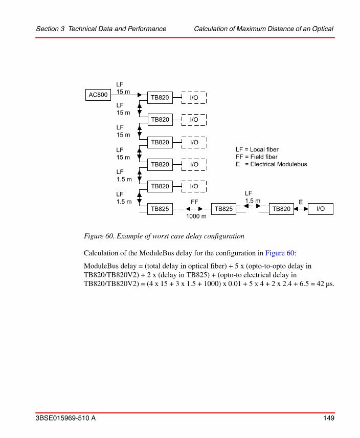
Section 3 Technical Data and Performance Calculation of Maximum Distance of an Optical
3BSE015969-510 A 149
Calculation of the ModuleBus delay for the configuration in Figure 60:
ModuleBus delay = (total delay in optical fiber) + 5 x (opto-to-opto delay in TB820/TB820V2) + 2 x (delay in TB825) + (opto-to electrical delay in TB820/TB820V2) = (4 x 15 + 3 x 1.5 + 1000) x 0.01 + 5 x 4 + 2 x 2.4 + 6.5 = 42 µs.
Figure 60. Example of worst case delay configuration
AC800
LF15 m
LF15 m
LF15 m
LF15 m
LF1.5 m
LF1.5 m FF
1000 m
LF1.5 m E
TB820
TB820
TB820
TB820
TB820
TB825
I/O
I/O
I/O
I/O
I/O
TB825 TB820 I/O
LF = Local fiberFF = Field fiberE = Electrical Modulebus
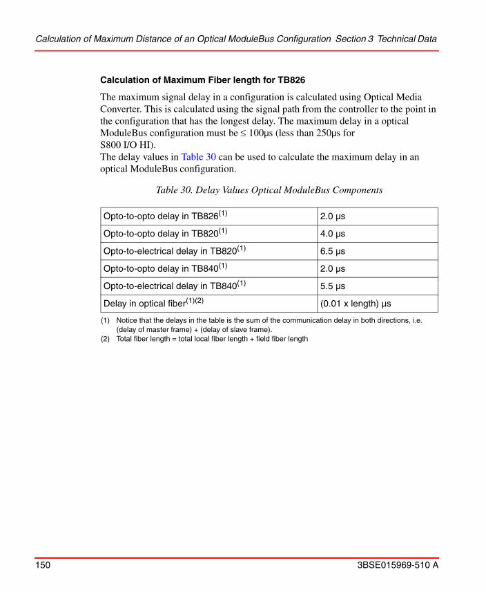
Calculation of Maximum Distance of an Optical ModuleBus Configuration Section 3 Technical Data
150 3BSE015969-510 A
Calculation of Maximum Fiber length for TB826
The maximum signal delay in a configuration is calculated using Optical Media Converter. This is calculated using the signal path from the controller to the point in the configuration that has the longest delay. The maximum delay in a optical ModuleBus configuration must be 100µs (less than 250µs for S800 I/O HI).The delay values in Table 30 can be used to calculate the maximum delay in an optical ModuleBus configuration.
Table 30. Delay Values Optical ModuleBus Components
Opto-to-opto delay in TB826(1)
(1) Notice that the delays in the table is the sum of the communication delay in both directions, i.e. (delay of master frame) + (delay of slave frame).
2.0 µs
Opto-to-opto delay in TB820(1) 4.0 µs
Opto-to-electrical delay in TB820(1) 6.5 µs
Opto-to-opto delay in TB840(1) 2.0 µs
Opto-to-electrical delay in TB840(1) 5.5 µs
Delay in optical fiber(1)(2)
(2) Total fiber length = total local fiber length + field fiber length
(0.01 x length) µs

Section 3 Technical Data and Performance Calculation of Maximum Distance of an Optical
3BSE015969-510 A 151
For the configuration in Figure 61 the Communication link delay is calculated as:
(Total delay in FF) + (Total delay in LF) + 6*(Opto-to-opto delay in TB820/TB820V2) + 2*(Delay in TB826) + (Opto-to-electrical delay in TB820)
= 5000*0.01 + ((7 * 200)+100)*0.01 + 6*4 + 2*2.0 + 6.5 = 50 + 1500*0.01 + 24 + 4 + 6.5= 99.5 µs
Figure 61. Example of worst case delay configuration TB826

Power Supply and Cooling Requirements Section 3 Technical Data and Performance
152 3BSE015969-510 A
Power Supply and Cooling Requirements
A quick guide for power consumption to be used in a preliminary phase of a project work or whenever you need estimated figures is provided in Table 31.
Table 31. Estimated System Power Consumption
S800 I/O Station24 V d.c.
Power Consumption (A)
Base cluster, single FCI, with six (6) I/O Modules 0.5
Base cluster, single FCI, with twelve (12) I/O Modules 1.0
Base cluster, redundant FCIs (2), with six (6) I/O Modules 1.0
Base cluster, redundant FCIs (2), with twelve (12) I/O Modules 1.5
Base cluster, redundant FCIs (2), with six (6) pairs of redundant I/O Modules
1.5
Additional I/O cluster with six (6) I/O Modules 0.5
Additional I/O cluster with twelve (12) I/O Modules 1.0
Additional I/O cluster, redundant Optical ModuleBus modem (2), with six (6) pairs of redundant I/O Modules(1)
(1) One pair of redundant I/O Modules counts as two I/O Modules.
1.0
Additional I/O cluster, redundant Optical ModuleBus modem (2), with twelve (12) I/O Modules
1.5
Additional I/O cluster, redundant Optical ModuleBus modem (2), with six (6) I/O Modules
1
The estimates are based on fully loaded I/O stations with a mixed configuration of DI/DO and AI/AO.Only power distributed via the ModuleBus are included. External 24 V connected directly to the I/O modules for external loads and transmitters are not included.When using AO820 and/or DO820/DO821, these load figures may be exceeded and a load calculation can be useful to do, see Table 32.

Section 3 Technical Data and Performance Power Supply and Cooling Requirements
3BSE015969-510 A 153
Power and Cooling
Table 32 shows the typical power and cooling values that can be used when designing the S800 I/O. (Calculation of 24V d.c. Power Consumption.)
Table 32. I/O Station Power and Cooling (Typical) Values
Device5 Volts
ModuleBus24 Volts
ModuleBus24 VoltsExternal
Power Dissipation
(Watts)
Cooling Load (1)
(BTU/H Typical)
Maximum Ambient Temperature
AI801 70 mA - 30 mA 1.1 3.7 55/40C (131/104F)(2)
AI810 70 mA 40 mA - 1.5 5.1 55/40C (131/104F)(2)
AI815 100 mA 50 mA 22 mA + sensor current
3.5 12 55/40C (131/104F)(2)
AI820 80 mA 70 mA - 1.7 5.8 55/40C (131/104F)(2)
AI825 100 mA 110 mA - 3.2 11 55/40C (131/104F)(2)
AI830/AI830A
70 mA 50 mA - 1.6 7.5 55/40C (131/104F)(2)
AI835/AI835A
75 mA 50 mA - 1.6 5.4 55/40C (131/104F)(2)
AI843 60 mA 50 mA - 1.5 5.1 55/40C (131/104F)(2)
AI845 100 mA 50 mA 22 mA + sensor current
3.5 12 55/40C (131/104F)(2)
AI880/AI880A
45 mA 50 mA 4 mA + sensor current
2.4 8.2 55/40C (131/104F)(2)
AI890 150 mA - 300 mA including sensor current
3.3 11 55/40C (131/104F)(2)
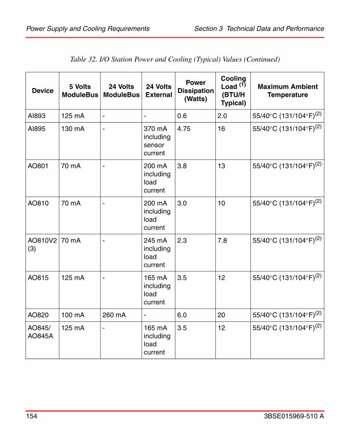
Power Supply and Cooling Requirements Section 3 Technical Data and Performance
154 3BSE015969-510 A
AI893 125 mA - - 0.6 2.0 55/40C (131/104F)(2)
AI895 130 mA - 370 mA including sensor current
4.75 16 55/40C (131/104F)(2)
AO801 70 mA - 200 mA including load current
3.8 13 55/40C (131/104F)(2)
AO810 70 mA - 200 mA including load current
3.0 10 55/40C (131/104F)(2)
AO810V2(3)
70 mA - 245 mA including load current
2.3 7.8 55/40C (131/104F)(2)
AO815 125 mA - 165 mA including load current
3.5 12 55/40C (131/104F)(2)
AO820 100 mA 260 mA - 6.0 20 55/40C (131/104F)(2)
AO845/AO845A
125 mA - 165 mA including load current
3.5 12 55/40C (131/104F)(2)
Table 32. I/O Station Power and Cooling (Typical) Values (Continued)
Device5 Volts
ModuleBus24 Volts
ModuleBus24 VoltsExternal
Power Dissipation
(Watts)
Cooling Load (1)
(BTU/H Typical)
Maximum Ambient Temperature

Section 3 Technical Data and Performance Power Supply and Cooling Requirements
3BSE015969-510 A 155
AO890 150 mA - 300 mA including load current
3.5 12 55/40C (131/104F)(2)
AO895 130 mA - 330 mA including load current
4.25 14.5 55/40C (131/104F)(2)
CI801 - - 140 mA 5.4 W(3) 19 55/40C (131/104F)(10)
CI810 - - 110 mA 2.6 8.9 55C/(131F)
CI820/CI820V1
- - 250 mA (4)
6.0 20 55C/(131F)
CI840/CI840A
- - 190 mA(4) 7.7 26 55/40C (131/104F)(10)
DI801 70 mA - - 2.2 7.5 55/40C (131/104F)(2)
DI802 50 mA - - 2.8 9.6 55/40C (131/104F)(2)
DI803 50 mA - - 2.8 9.6 55/40C (131/104F)(2)
DI810 50 mA - - 1.8 6.1 55/40C (131/104F)(2)
DI811 50 mA - - 2.7 9.2 55/40C (131/104F)(2)
DI814 50 mA - - 1.8 6.1 55/40C (131/104F)(2)
DI818 70mA - 25mA 3.1 55/40°C (131/104°F)(2)
DI820 50 mA - - 2.8 9.6 55/40C (131/104F)(2)
DI821 50 mA - - 2.8 9.6 55/40C (131/104F)(2)
Table 32. I/O Station Power and Cooling (Typical) Values (Continued)
Device5 Volts
ModuleBus24 Volts
ModuleBus24 VoltsExternal
Power Dissipation
(Watts)
Cooling Load (1)
(BTU/H Typical)
Maximum Ambient Temperature

Power Supply and Cooling Requirements Section 3 Technical Data and Performance
156 3BSE015969-510 A
DI828 45 mA - - 3.5 - 55/40°C (131/104°F)(2)
DI825 90 mA - - 4.9 15 55/40C (131/104F)(2)
DI830 120 mA - - 2.3 7.8 55/40C (131/104F)(2)
DI831 120 mA - - 3.2 11 55/40C (131/104F)(2)
DI840 100 mA - 15 mA + sensor current
2.7 9.0 55/40C (131/104F)(2)
DI880 125 mA - 15 mA + sensor current
2.4 8.2 55/40C (131/104F)(2)
DI885 160 mA 91 mA(5) 91 mA(5) 3.0 10 55/40C (131/104F)(2)
DI890 150 mA - 70 mA including sensor current
1.6 5.4 55/40C (131/104F)(2)
DO801 80 mA - (6) 2.1 7.2 55/40C (131/104F)(2)
DO802 70 mA 80 mA - 2.2 7.5 55/40C (131/104F)(2)
DO810 80 mA - (6) 2.1 7.2 55/40C (131/104F)(2)
DO814 80 mA - (6) 2.1 7.2 55/40C (131/104F)(2)
DO815 120 mA - (7) 4.0 14 55/40C (131/104F)(2)
DO818 70 mA - 40 mA 2.8 55/40°C (131/104°F)(2)
DO820 60 mA 140 mA - 2.9 9.9 55/40C (131/104F)(2)
DO821 60 mA 140 mA - 2.9 9.9 55/40C (131/104F)(2)
DO828 45 mA 80 mA - 3.5 - 55/40C (131/104F)(2)
Table 32. I/O Station Power and Cooling (Typical) Values (Continued)
Device5 Volts
ModuleBus24 Volts
ModuleBus24 VoltsExternal
Power Dissipation
(Watts)
Cooling Load (1)
(BTU/H Typical)
Maximum Ambient Temperature

Section 3 Technical Data and Performance Power Supply and Cooling Requirements
3BSE015969-510 A 157
DO840 130 mA - 200 mA +channel load(6)
4.3 14 55/40C (131/104F)(2)
DO880 45 mA 55 mA 10 mA +channel load(6)(8)
5.6(9) 19 55/40C (131/104F)(2)
DO890 150 mA - 360 mA 4.4 15 55/40C (131/104F)(2)
DP820 120 mA - (6) 2.5 8.5 55/40C (131/104F)(2)
DP840 115 mA - 70 mA(6) 4.0 14 55/40C (131/104F)(2)
TB810 100 mA 20 mA - 0.5 1.7 55C/(131F)
TB811 100 mA 20 mA - 0.5 1.7 55C/(131F)
TB820/TB820V2
- - 100 mA 6.0 20 55C/(131F)
TB825 - - 96 mA 2.3 7.8 55C/(131F)
TB826 - - 92 mA 2.2 7.8 55C/(131F)
TB840 - - 120 mA(4) 6.0 20 55/40C (131/104F)(10)
TB842 100 mA 20 mA - 0.5 1.7 55C/(131F)
SD831 - - - 10/8(11) 34/27 55C/(131F)(12)
SD832 - - - 14/13(11) 47/44 55C/(131F)(12)
SD833 - - - 24/22(11) 81/75 55C/(131F)(12)
SD834 40/31(11) 136/105 55C/(131F)(12)
Table 32. I/O Station Power and Cooling (Typical) Values (Continued)
Device5 Volts
ModuleBus24 Volts
ModuleBus24 VoltsExternal
Power Dissipation
(Watts)
Cooling Load (1)
(BTU/H Typical)
Maximum Ambient Temperature

Power Supply and Cooling Requirements Section 3 Technical Data and Performance
158 3BSE015969-510 A
SS823 - - - 24 82 55C/(131F)(12)
SS832 - - - 7.9 27 55C/(131F)(12)
(1) Cooling load is the heat (BTU/H) produced by the equipment that may be required to meet room or enclosure cooling specifications.
(2) 40C(104F) applies to Compact MTUs with I/O modules or S800L mounted on a vertical DIN-rail. (3) With maximum load at ModuleBus 24 V and 5V(4) In redundant configuration twice(5) 24 V from ModuleBus (91 mA) or 24 V external (91 mA) or 48 V external (22 mA).(6) 500 mA per channel with maximum load per channel. (7) 2 A per channel with maximum load per channel.(8) Short circuit current <15 A during 20 ms.(9) With maximum channel load(10) 40C(104F) mounter on a vertical DIN-rail.(11) a.c. 120/230V.(12) Horizontal mounting only.
Table 32. I/O Station Power and Cooling (Typical) Values (Continued)
Device5 Volts
ModuleBus24 Volts
ModuleBus24 VoltsExternal
Power Dissipation
(Watts)
Cooling Load (1)
(BTU/H Typical)
Maximum Ambient Temperature

Section 3 Technical Data and Performance Power Supply and Cooling Requirements
3BSE015969-510 A 159
Calculation of 24V d.c. Power Consumption
Total 24 V d.c. current consumption = V load ModuleBus + V load ModuleBus*0.3 + V external load.
The calculated 5 V ModuleBus load should not exceed 1.5 A.
If many of the modules has a power consumption >125 mA at 5 V, the maximum load could be exceeded. See Table 32 for data.
The calculated 24 V ModuleBus load should not exceed 1.4 A.
If many of the modules has a power consumption >125 mA at 24 V, the maximum load could be exceeded.
To ensure bumpless performance of the I/O system including DO880, the power supply for the I/O field power should be able to support at least short circuit on one DO880 channel in addition to the total nominal load. For Short circuit current for DO880, see Technical Data in S800 I/O Modules and Termination Units.
The following rules must be considered if ABB power supply units are being used together with DO880.
- When using SS823, the base load must not exceed 16 A.
- With a redundant power supply configuration, consisting of two SD823 + one SS823 in parallel with two SD823 + one SS823, the base load must not exceed 16 A.

Power Supply and Cooling Requirements Section 3 Technical Data and Performance
160 3BSE015969-510 A
I/O Module MTU Combination and Key Setting
Each MTU is used with certain types of I/O Modules. Refer to Table 33 and Table 34 for a cross-reference between MTU and I/O Modules. Each MTU has two mechanical keys that have to be set for the type of I/O module that will be installed on it.
Table 33. MTU Usage and Key Settings
Module Type T
U81
0
TU
812
TU
814
Co
mp
act
TU
818
Co
mp
act
TU
819
Co
mp
act
TU
811
TU
813
Co
mp
act
TU
830
TU
833
Ext
end
ed
TU
831
Ext
end
ed
TU
834
Ext
end
ed
TU
835
Ext
end
ed
TU
836
TU
837
TU
838
Ext
end
ed
TU
839
Ext
end
ed
TU
842
TU
843
TU
852
Red
un
dan
t
TU
844
TU
845
TU
854
Red
un
dan
t
TU
850
Ext
end
ed
TU
851
Ext
end
ed
Mech. Key
Setting
Key 1
Key 2
AI810 X X X - - X - - X - X - - - X - A E
AI815 X X X - - X - - X - X - - - - - C C
AI820 X X - - - X - - - - - - - - - - B B
AI825 - - - - X - X - - - - - - - - - D A
AI830/AI830A X
X - - - X - - - - - - - - - - A F
AI835/
AI835A XX
X- - X - - - - - - - - - - B A
AI843 - - X - - X - - - - - - X - - - B A
AI845 X X X - - X - - X - X - - X - - C C
AI880 - - - - - - - X - - - - - X - - F F
AI880A - - - - - - - X - - - - - X - - F D
AO810/AO810V2 X
X - - - X - - - - - - - - - - A E
AO815 X X - - - X - - - - - - - - - - D B

Section 3 Technical Data and Performance Power Supply and Cooling Requirements
3BSE015969-510 A 161
AO820 X X - - - X - - - - - - - - - - B C
AO845 X - - - X - - - - - - X - - - C C
AO845A X X - - - X - - - - - - X - - - D B
DI810 X X X - - X - - - - X - - - X - A A
DI811 X X X - - X - - - - X - - - X - B D
DI814 X X - - - X - - - - X - - - - - B E
DI818 - - X X - X - - - - - - - - - - E A
DI820 - - - - X - X - - - - X - - - X A B
DI821 - - - - X - X - - - - X - - - X A C
DI825 - - - - X - X - - - - X - - - X A B
DI828 - - - - - - - - - - - - - - - X E B
DI830 X X X - - X - - - - X - - - X - A A
DI831 X X X - - X - - - - X - - - X - B D
DI840 X X X - - X - - - - X - X - - - C D
DI880 X X(1) X - - X(2) - - - - - - X(2) - - - F F
DI885 X X X - - X - - - - - - - - - - B F
DO810 X X - - - X - - - - - - - - - - A A
DO814 X X - - - X - - - - X - - - - - B E
Table 33. MTU Usage and Key Settings (Continued)
Module Type T
U81
0
TU
812
TU
814
Co
mp
act
TU
818
Co
mp
act
TU
819
Co
mp
act
TU
811
TU
813
Co
mp
act
TU
830
TU
833
Ext
end
ed
TU
831
Ext
end
ed
TU
834
Ext
end
ed
TU
835
Ext
end
ed
TU
836
TU
837
TU
838
Ext
end
ed
TU
839
Ext
end
ed
TU
842
TU
843
TU
852
Red
un
dan
t
TU
844
TU
845
TU
854
Red
un
dan
t
TU
850
Ext
end
ed
TU
851
Ext
end
ed
Mech. Key
Setting
Key 1
Key 2
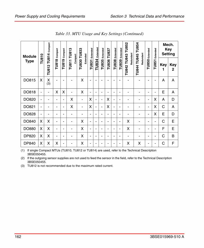
Power Supply and Cooling Requirements Section 3 Technical Data and Performance
162 3BSE015969-510 A
DO815 X X (3)
- - - X - - - - - - - - - - A A
DO818 - - X X - X - - - - - - - - - - E A
DO820 - - - - X - X - - X - - - - - X A D
DO821 - - - - X - X - - X - - - - - X C A
DO828 - - - - - - - - - - - - - - - X E D
DO840 X X - - - X - - - - - - X - - - C E
DO880 X X - - - X - - - - - - X - - - F E
DP820 X X - - - X - - - - - - - - - - C B
DP840 X X X - - X - - - - - - X X - - C F
(1) If single Compact MTUs (TU810, TU812 or TU814) are used, refer to the Technical Description 3BSE050455.
(2) If the outgoing sensor supplies are not used to feed the sensor in the field, refer to the Technical Description 3BSE050455.
(3) TU812 is not recommended due to the maximum rated current.
Table 33. MTU Usage and Key Settings (Continued)
Module Type T
U81
0
TU
812
TU
814
Co
mp
act
TU
818
Co
mp
act
TU
819
Co
mp
act
TU
811
TU
813
Co
mp
act
TU
830
TU
833
Ext
end
ed
TU
831
Ext
end
ed
TU
834
Ext
end
ed
TU
835
Ext
end
ed
TU
836
TU
837
TU
838
Ext
end
ed
TU
839
Ext
end
ed
TU
842
TU
843
TU
852
Red
un
dan
t
TU
844
TU
845
TU
854
Red
un
dan
t
TU
850
Ext
end
ed
TU
851
Ext
end
ed
Mech. Key
Setting
Key 1
Key 2
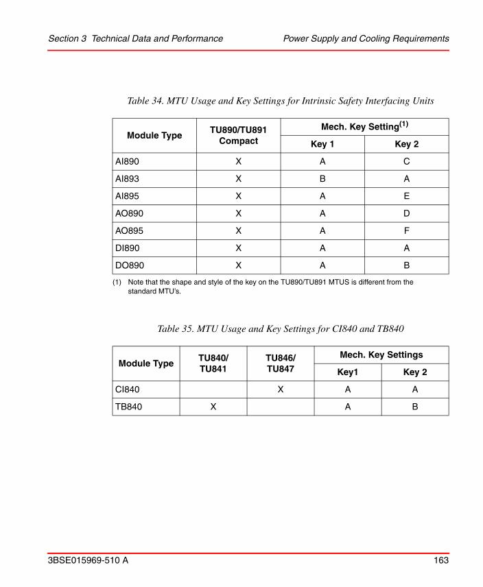
Section 3 Technical Data and Performance Power Supply and Cooling Requirements
3BSE015969-510 A 163
Table 34. MTU Usage and Key Settings for Intrinsic Safety Interfacing Units
Module TypeTU890/TU891
Compact
Mech. Key Setting(1)
(1) Note that the shape and style of the key on the TU890/TU891 MTUS is different from the standard MTU’s.
Key 1 Key 2
AI890 X A C
AI893 X B A
AI895 X A E
AO890 X A D
AO895 X A F
DI890 X A A
DO890 X A B
Table 35. MTU Usage and Key Settings for CI840 and TB840
Module TypeTU840/TU841
TU846/TU847
Mech. Key Settings
Key1 Key 2
CI840 X A A
TB840 X A B

Supported I/O Modules and Drives via Advant Fieldbus 100 Section 3 Technical Data and
164 3BSE015969-510 A
Supported I/O Modules and Drives via Advant Fieldbus 100
The following I/O modules are supported by the Advant Fieldbus 100 Field Communication Interface module CI810 and CI820:
• AI801, AI810, AI820, AI830, AI830A, AI835, AI890, AI895
• AO801, AO810, AO810V2, AO820, AO890, AO895
• DI801, DI810, DI811, DI814, DI820, DI821, DI830, DI831, DI885, DI890
• DO801, DO810, DO814, DO815, DI820, DO821, DO890
• DP820
• ABB Standard Drives
• ABB Engineered Drives
Supported I/O Modules and Drives via PROFIBUS and CI801
The following I/O modules are supported by the PROFIBUS Field Communication Interface module CI801:
• AI801, AI810, AI815, AI820, AI825, AI830, AI830A, AI835, AI843, AI845, AI890, AI893, AI895
• AO801, AO810, AO815, AO810V2, AO820, AO845, AO845A, AO890, AO895
• DI801, DI802, DI803, DI810, DI811, DI814, DI818, DI820, DI821, DI828, DI840 (SOE handling not supported), DI890
• DO801, DO802, DO810, DO814, DO815, DO818, DO820, DO821, DO828, DO840, DO890
• DP820, DP840
• ABB Standard Drives (Equipped with opto transmitter/receiver for up to 10 Mbit/s on the ModuleBus.)
– ACS600/ACS800 with standard application
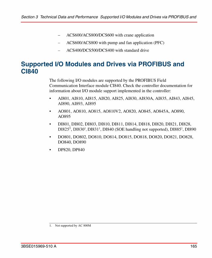
Section 3 Technical Data and Performance Supported I/O Modules and Drives via PROFIBUS and
3BSE015969-510 A 165
– ACS600/ACS800/DCS600 with crane application
– ACS600/ACS800 with pump and fan application (PFC)
– ACS400/DCS500/DCS400 with standard drive
Supported I/O Modules and Drives via PROFIBUS and CI840
The following I/O modules are supported by the PROFIBUS Field Communication Interface module CI840. Check the controller documentation for information about I/O module support implemented in the controller:
• AI801, AI810, AI815, AI820, AI825, AI830, AI830A, AI835, AI843, AI845, AI890, AI893, AI895
• AO801, AO810, AO815, AO810V2, AO820, AO845, AO845A, AO890, AO895
• DI801, DI802, DI803, DI810, DI811, DI814, DI818, DI820, DI821, DI828, DI8251, DI8301, DI8311, DI840 (SOE handling not supported), DI8851, DI890
• DO801, DO802, DO810, DO814, DO815, DO818, DO820, DO821, DO828, DO840, DO890
• DP820, DP840
1. Not supported by AC 800M
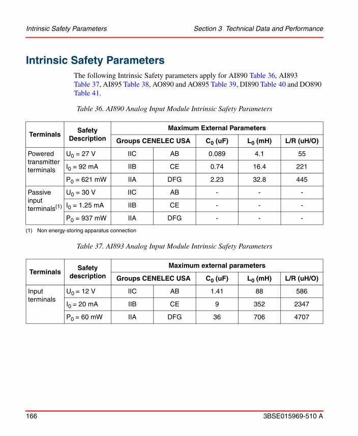
Intrinsic Safety Parameters Section 3 Technical Data and Performance
166 3BSE015969-510 A
Intrinsic Safety ParametersThe following Intrinsic Safety parameters apply for AI890 Table 36, AI893 Table 37, AI895 Table 38, AO890 and AO895 Table 39, DI890 Table 40 and DO890 Table 41.
Table 36. AI890 Analog Input Module Intrinsic Safety Parameters
TerminalsSafety
Description
Maximum External Parameters
Groups CENELEC USA C0 (uF) L0 (mH) L/R (uH/O)
Powered transmitter terminals
U0 = 27 V IIC AB 0.089 4.1 55
I0 = 92 mA IIB CE 0.74 16.4 221
P0 = 621 mW IIA DFG 2.23 32.8 445
Passive input terminals(1)
(1) Non energy-storing apparatus connection
U0 = 30 V IIC AB - - -
I0 = 1.25 mA IIB CE - - -
P0 = 937 mW IIA DFG - - -
Table 37. AI893 Analog Input Module Intrinsic Safety Parameters
TerminalsSafety
description
Maximum external parameters
Groups CENELEC USA C0 (uF) L0 (mH) L/R (uH/O)
Input terminals
U0 = 12 V IIC AB 1.41 88 586
I0 = 20 mA IIB CE 9 352 2347
P0 = 60 mW IIA DFG 36 706 4707

Section 3 Technical Data and Performance Intrinsic Safety Parameters
3BSE015969-510 A 167
Table 38. AI895 Analog Input Module Intrinsic Safety Parameters
TerminalsSafety
Description
Maximum External Parameters
Groups CENELEC USA C0 (uF) L0 (mH) L/R (uH/O)
1-10, 2-113-12, 4-135-14, 6-157-16, 8-17
U0 = 27 V IIC AB 0.087 4.1 55
I0 = 93 mA IIB CE 0.702 16.4 222
P0 = 630 mW IIA DFG 2.23 32.8 443
Table 39. AO890/AO895 Analog Output Module Intrinsic Safety Parameters
TerminalsSafety
description
Maximum external parameters
Groups CENELEC USA C0 (uF) L0 (mH) L/R (uH/O)
Powered output terminals
U0 = 27 V IIC AB 0.097 4.1 58
I0 = 93 mA IIB CE 0.74 16.5 230
P0 = 620 mW IIA DFG 2.51 33 470
Table 40. DI890 Digital Input Module Intrinsic Safety Parameters
TerminalsSafety
description
Maximum external parameters
Groups CENELEC USA C0 (uF) L0 (mH) L/R (uH/O)
Input terminals
U0 = 11V IIC AB 1.97 80 595
I0 = 21 mA IIB CE 13.8 320 2382
P0 = 0.058 mW
IIA DFG 60 640 4765

Intrinsic Safety Parameters Section 3 Technical Data and Performance
168 3BSE015969-510 A
Table 41. DO890 Digital Input Module Intrinsic Safety Parameters
TerminalsSafety
description
Maximum external parameters
Groups CENELEC USA C0 (uF) L0 (mH) L/R (uH/O)
Powered output terminals
U0 = 26 V IIC AB 0.099 4.1 58
I0 = 93 mA IIB CE 0.77 16.4 234
P0 = 605 mW IIA DFG 2.6 32.8 469

Section 3 Technical Data and Performance Certifications
3BSE015969-510 A 169
CertificationsThe S800 I/O system is continuously enhanced with additional certificates. The table below describes the situation at the printing of this Product Guide.
Table 42. Current Certifications for S800 Modules
Module Type
CE
cULusEl. safetyHaz locC1 Zone
2(1)
FMEl. safetyHaz loc
C1, Div 2
CSAEl. safetyHaz loc
C1, Div 2
ATEX Zone 2
Category 3 (1) G (2)
ATEX Zone 2 Category
3 G (3)SIL1-3
cULusEl. safety
Analog Input Modules
AI801 X X X X
AI810 X X X X
AI820 X X X X
AI815 X X
AI825 X X
AI830 X X X X
AI830A X X X X
AI835 X X X X
AI835A X X X X
AI843 X X
AI845 X X
AI880/AI880A
X X X X
AI890 X X(4) X(4) X
AI893 X X
AI895 X X(4) X(4) X

Certifications Section 3 Technical Data and Performance
170 3BSE015969-510 A
Analog Output Modules
AO801 X X X X
AO810 X X X X
AO810V2 X X X X
AO815 X X
AO820 X X X X
AO845 X X
AO845A X X
AO890 X X(4) X(4) X
AO895 X X(4) X(4) X
Field Communication Interface
CI801 X X
CI810B X X X X
CI820V1 X X X X
CI830 X X X X
CI840 X X
CI840A X X
TB815 X X X X
Table 42. Current Certifications for S800 Modules (Continued)
Module Type
CE
cULusEl. safetyHaz locC1 Zone
2(1)
FMEl. safetyHaz loc
C1, Div 2
CSAEl. safetyHaz loc
C1, Div 2
ATEX Zone 2
Category 3 (1) G (2)
ATEX Zone 2 Category
3 G (3)SIL1-3
cULusEl. safety
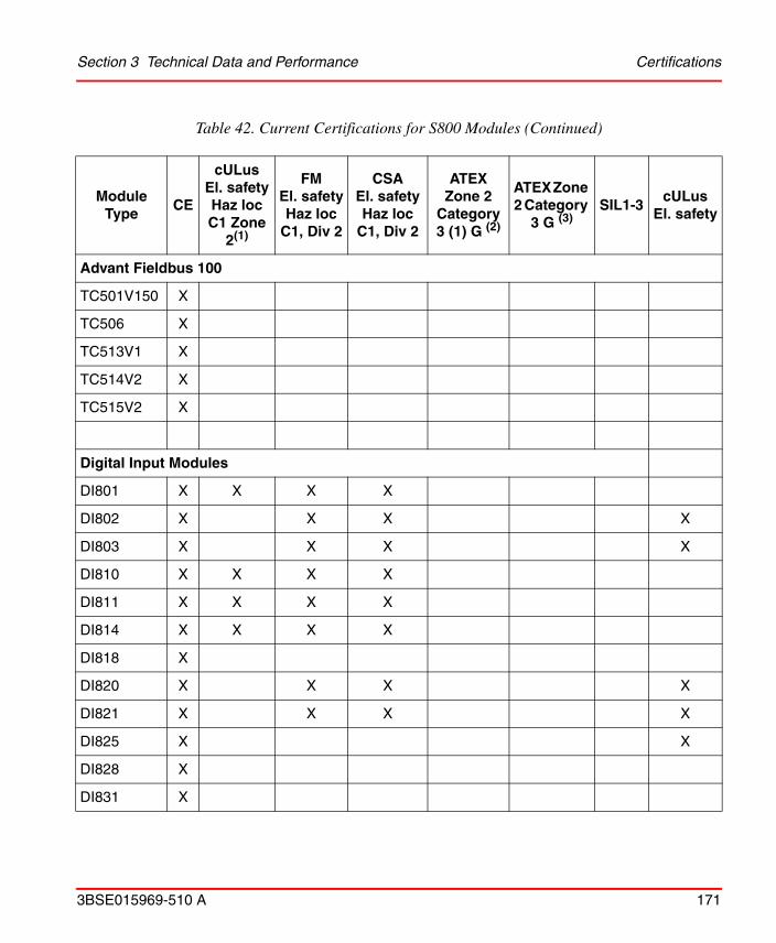
Section 3 Technical Data and Performance Certifications
3BSE015969-510 A 171
Advant Fieldbus 100
TC501V150 X
TC506 X
TC513V1 X
TC514V2 X
TC515V2 X
Digital Input Modules
DI801 X X X X
DI802 X X X X
DI803 X X X X
DI810 X X X X
DI811 X X X X
DI814 X X X X
DI818 X
DI820 X X X X
DI821 X X X X
DI825 X X
DI828 X
DI831 X
Table 42. Current Certifications for S800 Modules (Continued)
Module Type
CE
cULusEl. safetyHaz locC1 Zone
2(1)
FMEl. safetyHaz loc
C1, Div 2
CSAEl. safetyHaz loc
C1, Div 2
ATEX Zone 2
Category 3 (1) G (2)
ATEX Zone 2 Category
3 G (3)SIL1-3
cULusEl. safety

Certifications Section 3 Technical Data and Performance
172 3BSE015969-510 A
DI830 X X X X
DI831 X X X X
DI840 X X
DI880 X X X X
DI885 X X X X
DI890 X X(4) X(4) X
Digital Output Modules
DO801 X X X X
DO802 X X X X
DO810 X X X X
DO814 X X X X
DO815 X X X X
DO818 X
DO820 X X X X
DO821 X X X X
DO828 X
DO840 X X
DO880 X X X X
DO890 X X(4) X(4) X
Table 42. Current Certifications for S800 Modules (Continued)
Module Type
CE
cULusEl. safetyHaz locC1 Zone
2(1)
FMEl. safetyHaz loc
C1, Div 2
CSAEl. safetyHaz loc
C1, Div 2
ATEX Zone 2
Category 3 (1) G (2)
ATEX Zone 2 Category
3 G (3)SIL1-3
cULusEl. safety

Section 3 Technical Data and Performance Certifications
3BSE015969-510 A 173
SD821(5) X X
SD822(5) X X
SD823(5) X X X
SS822(5) X X
SD832 X X
SD833 X X
SD834 X X X
SS823 X X X X
SS832 X X
Pulse Counting Modules
DP820 X X X X
DP840 X X
Module Termination Units
TU801 X
TU807 X X
TU810V1 X X X X
TU811V1 X X X X
TU812V1 X X X X
Table 42. Current Certifications for S800 Modules (Continued)
Module Type
CE
cULusEl. safetyHaz locC1 Zone
2(1)
FMEl. safetyHaz loc
C1, Div 2
CSAEl. safetyHaz loc
C1, Div 2
ATEX Zone 2
Category 3 (1) G (2)
ATEX Zone 2 Category
3 G (3)SIL1-3
cULusEl. safety
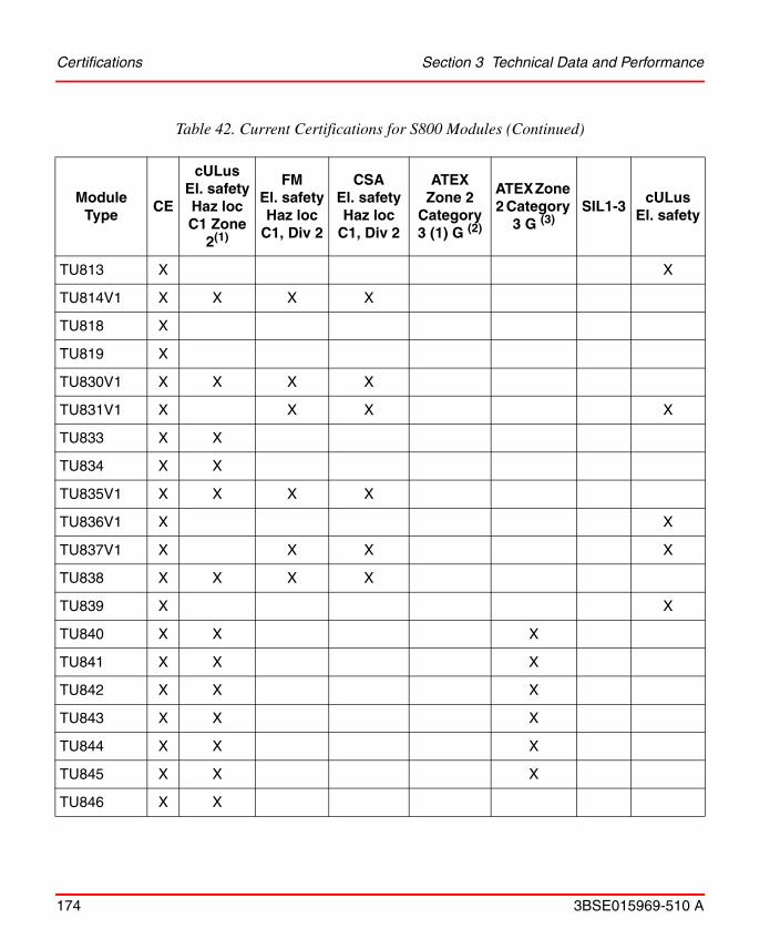
Certifications Section 3 Technical Data and Performance
174 3BSE015969-510 A
TU813 X X
TU814V1 X X X X
TU818 X
TU819 X
TU830V1 X X X X
TU831V1 X X X X
TU833 X X
TU834 X X
TU835V1 X X X X
TU836V1 X X
TU837V1 X X X X
TU838 X X X X
TU839 X X
TU840 X X X
TU841 X X X
TU842 X X X
TU843 X X X
TU844 X X X
TU845 X X X
TU846 X X
Table 42. Current Certifications for S800 Modules (Continued)
Module Type
CE
cULusEl. safetyHaz locC1 Zone
2(1)
FMEl. safetyHaz loc
C1, Div 2
CSAEl. safetyHaz loc
C1, Div 2
ATEX Zone 2
Category 3 (1) G (2)
ATEX Zone 2 Category
3 G (3)SIL1-3
cULusEl. safety
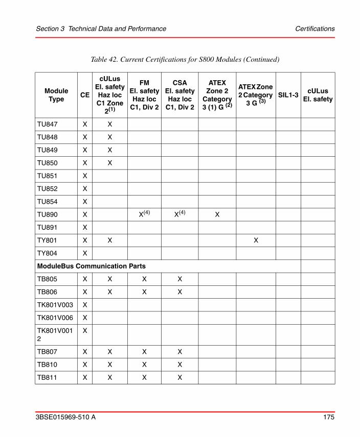
Section 3 Technical Data and Performance Certifications
3BSE015969-510 A 175
TU847 X X
TU848 X X
TU849 X X
TU850 X X
TU851 X
TU852 X
TU854 X
TU890 X X(4) X(4) X
TU891 X
TY801 X X X
TY804 X
ModuleBus Communication Parts
TB805 X X X X
TB806 X X X X
TK801V003 X
TK801V006 X
TK801V0012
X
TB807 X X X X
TB810 X X X X
TB811 X X X X
Table 42. Current Certifications for S800 Modules (Continued)
Module Type
CE
cULusEl. safetyHaz locC1 Zone
2(1)
FMEl. safetyHaz loc
C1, Div 2
CSAEl. safetyHaz loc
C1, Div 2
ATEX Zone 2
Category 3 (1) G (2)
ATEX Zone 2 Category
3 G (3)SIL1-3
cULusEl. safety

Certifications Section 3 Technical Data and Performance
176 3BSE015969-510 A
TB820V2 X X X X
TB825 X X
TB826 X X
TB840/TB840A
X X X
TB842 X X
TB845 X X
TB846 X X
(1) Marking for mounting and interface: Class 1 Zone 2 AEx nC (or nA) IIC T4 and CL 1 DIV 2 GP A B C D T4(2) Marking for mounting: Ex II 3G EEx nA [ia] IIC T4
Marking for interface: Ex II (1)G [EEx ia] IIC (3) Marking for mounting and interface: Ex II 3G Ex nA IIC T5 Gc(4) Provides Intrinsically safe circuit for Cl. I, Div 1; Cl. II, Div. 1; Cl. III, Div 1 or Cl. I, Zone 0 group IIc(5) cULus; UL508, UL1950, CSA 22.2 No 950
Table 42. Current Certifications for S800 Modules (Continued)
Module Type
CE
cULusEl. safetyHaz locC1 Zone
2(1)
FMEl. safetyHaz loc
C1, Div 2
CSAEl. safetyHaz loc
C1, Div 2
ATEX Zone 2
Category 3 (1) G (2)
ATEX Zone 2 Category
3 G (3)SIL1-3
cULusEl. safety

3BSE015969-510 A 177
Section 4 Ordering
GeneralThis Product Guide aims to help ABB sales representatives when ordering the S800 I/O product and licenses.
This section describes the price lists needed when ordering and provides ordering examples.
However, it is outside the scope of this Product Guide to give a complete description of all ordering procedures and tools, as well as licensing conditions for other IndustrialIT products. Each ABB sales representative is assumed to know how to use price lists, CAST and other tools to order.
Product and Price List Structure
S800 I/O is ordered as separate parts. From the current price list, you order the modules you need for your system.
For further details, refer the valid S800 I/O Price List.

Product and Price List Structure Section 4 Ordering
178 3BSE015969-510 A

3BSE015969-510 A 179
AAdvant Fieldbus 100 19AI801 50AI810 50, 58AI815 50AI820 50AI825 51AI830/ AI830A 51AI830A 51AI835/ AI835A 51AI843 51AI845 52AI880/ AI880A 52AI890 52AI893 52AI895 52AO801 52AO810 58AO810/ AO810V2 53AO810V2 53, 58AO815 53AO820 53AO845/ AO845A 53AO845A 53AO890 53AO895 53
BBuilt in 2/3 wire termination 109
CCalculation of 24V d.c. power consumption 153,
159CI801 36CI810 36
CI820/CI820V1 36CI840/ CI840A 36Compact MTUs 66Cooling load 153
DDI801 44DI802 44DI803 44DI810 44, 58DI811 45DI814 45DI818 45DI820 45DI821 45DI825 45DI828 45DI830 46DI831 46DI840 46DI880 46DI885 47DI890 47DO801 47DO802 47DO810 47, 58DO814 47DO815 47DO818 48DO820 48DO821 48DO828 48DO840 48DO880 48DO890 48
INDEX
Index
180 3BSE015969-510 A
Index
180 3BSE015969-510 A
DP820 49DP840 49
EExtension cables 88, 89
FFCI 11
HHART 11
II/O station 12
MMaximum ambient temperature 153Module Termination Units (MTU) 65
PPower and Cooling 153Power consumption 152Power Dissipation 153PROFIBUS-DP 12, 19, 28
SSD822Z 93SD831 93SD832 93SD833 93SD834 94SS822Z 94SS823 94SS832 94
TTB805 42TB806 42TB807 42
TB810 41TB811 41TB815 36, 41TB820/ TB820V2 41TB825 41TB826 41TB840/ TB840A 41TB842 41TB845 41TB846 41TK801V003 42TK801V006 42TK801V012 42TK811V015 42TK811V050 42TK811V150 42TK812V015 42TK812V050 42TK812V150 42TU805 37TU807 42TU810 37TU811 37TU812 58TU812/ TU812V1 37TU813 37TU814/ TU814V1 37TU830/ TU830V1 38TU831/ TU831V1 38TU833 38TU834 38TU835/ TU835V1 38TU836/ TU836V1 38TU837/ TU837V1 38TU838 38TU839 38TU840 42TU841 42TU842 39TU843 39
Index
3BSE015969-510 A 181
TU844 39TU845 39TU846 36TU847 36TU848 43TU849 43TU850 39TU890 39TU891 39TY801 39TY804 39TY820 39

Index
3BSE015969-510 A 182


ABB AB Control TechnologiesVästerås, SwedenPhone: +46 (0) 21 32 50 00e-mail: [email protected]/controlsystems
ABB S.P.A.Control TechnologiesSesto San Giovanni (MI), ItalyPhone: +39 02 24147 555e-mail: [email protected]/controlsystems
ABB Inc.Control TechnologiesWickliffe, Ohio, USAPhone: +1 440 585 8500e-mail: [email protected]/controlsystems
ABB Automation GmbHControl TechnologiesMannheim, GermanyPhone: +49 1805 26 67 76e-mail: [email protected]/controlsystems
Power and productivityfor a better worldTM
Contact us
ABB Pte LtdControl TechnologiesSingaporePhone: +65 6776 5711e-mail: [email protected]/controlsystems
ABB Automation LLCControl TechnologiesAbu Dhabi, United Arab EmiratesPhone: +971 (0) 2 4938 000e-mail: [email protected]/controlsystems
ABB China LtdControl TechnologiesBeijing, ChinaPhone: +86 (0) 10 84566688-2193www.abb.com/controlsystems
3BS
E01
5969
-510
A
Copyright © 2003-2013 by ABB.All rights reserved.