s3.amazonaws.com · 68 Lighting Guide 1: The industrial environment It is important to appreciate...
110
Lighting Guide 1: The industrial environment The Society of Light and Lighting This publication is supplied by CIBSE for the sole use of the person making the download. The content remains the copyright property of CIBSE
-
Upload
nguyennguyet -
Category
Documents
-
view
215 -
download
0
Transcript of s3.amazonaws.com · 68 Lighting Guide 1: The industrial environment It is important to appreciate...

Lighting Guide 1:The industrial environment
The Society of Light and Lighting is part of the
Chartered Institution of Building Services Engineers 9 7 8 1 9 0 6 8 4 6 2 8 2
ISBN 978-1-906846-28-2
Lighting Guide 1: The industrial environm
ent The Society of Light and Lighting
The Society ofLight and Lighting
LG1 cover v1.indd 1 12/11/2012 13:38
This publication is supplied by CIB
SE
for the sole use of the person making the dow
nload. The content remains the copyright property of C
IBS
E

The Society ofLight and Lighting
Lighting Guide 1:The Industrial Environment
222 Balham High Road, London SW12 9BS, UK
Tel: 020 8675 5211. Fax: 020 8673 3302. E-mail: [email protected]. www.sll.org.ukThe Society of Light and Lighting is part of the Chartered Institution of Building Services Engineers
This publication is supplied by CIB
SE
for the sole use of the person making the dow
nload. The content remains the copyright property of C
IBS
E

This document is based on the best knowledge available at the time of publication. However, no responsibility of any kind for any injury, death, loss, damage or delay however caused resulting from the use of these recommendations can be accepted by the Chartered Institution of Building Services Engineers, the Society of Light and Lighting, the authors or others involved in its publication. In adopting these recommendations for use each adopter by doing so agrees to accept full responsibility for any personal injury, death, loss, damage or delay arising out of or in connection with their use by or on behalf of such adopter irrespective of the cause or reason therefore and agrees to defend, indemnify and hold harmless the Chartered Institution of Building Services Engineers, The Society of Light and Lighting, the authors and others involved in their publication from any and all liability arising out of or in connection with such use as aforesaid and irrespective of any negligence on the part of those indemnified.
The rights of publication or translation are reserved.
No part of this publication may be reproduced, stored in a retrieval system or transmitted in any form or by any means without the prior permission of the publisher.
© November 2012 The Society of Light and Lighting
The Society is part of CIBSE, which is a registered charity, number 278104.
ISBN 978-1-906846-28-2
Production management, editing, layout and typesetting by The Charlesworth Group, Huddersfield, West Yorkshire HD2 1JJ.
Printed in England by The Lavenham Press, Lavenham, Suffolk CO10 9RN
Note from the publisher
This publication is primarily intended to provide guidance to those responsible for the design, installation, commissioning, operation and maintenance of building services. It is not intended to be exhaustive or definitive and it will be necessary for users of the guidance given to exercise their own professional judgement when deciding whether to abide by or depart from it.
Any commercial products depicted or described within this publication are included for the purposes of illustration only and their inclusion does not constitute endorsement or recommendation by the Society.
This publication is supplied by CIB
SE
for the sole use of the person making the dow
nload. The content remains the copyright property of C
IBS
E

Foreword This is the 2012 revision of the Guide on Lighting for Industry published by the Society of Light and Lighting, part of The Chartered Institution of Building Services Engineers. It is intended as an introduction to the subject of industrial lighting for lighting engineers, specifiers, users and students. It is essentially a compendium of experience. With the aim of making the guide suitable for a wide readership, the task group has concentrated upon the practical applications of lighting in industry and on giving proven solutions to practical problems. The guide also includes up-to-date legislation where relevant and incorporates best practice principles throughout. Individual industry characteristics have been aligned to BS EN 12464: Part 1: 2011 where possible, including the introduction of a distinction between task area and surrounding areas, and the subsequent recommendation of uniformity for those areas. Indeed, uniformity has been given far more importance throughout the Guide, with recommended minimum values in the tables appertaining to each particular industry.
The chairman would like to acknowledge the help of W Burt, Esq., and the time and facilities provided by the City of Manchester Council, the Electricity Council Research Centre, Engineering Design and Procurement Limited, the Merseyside and North Wales Electricity Board, Philips Lighting Ltd, and Thorn Lighting Ltd for work from the original Guide, and Hilclare Lighting for their assistance during the revision.
Task Group
David Holmes (Hilclare Ltd.) (Chairman)Peter Boyce (Technical Editor)
CIBSE Head of Knowledge
Nicholas Peake
This publication is supplied by CIB
SE
for the sole use of the person making the dow
nload. The content remains the copyright property of C
IBS
E

Contents 1 Introduction .......................................................................1
2 Lighting for industry .........................................................2
2.1 The illuminance on the task ......................................................................2
2.2 The plane of the task................................................................................2
2.3 llluminance uniformity ..............................................................................2
2.4 Obstruction ..............................................................................................4
2.5 Lighting of the general surroundings ........................................................4
2.6 Surface refl ectances .................................................................................4
2.7 Direct glare ..............................................................................................4
2.8 Glare by refl ection ....................................................................................5
2.9 Colour properties .....................................................................................5
2.10 Stroboscopic effects .................................................................................5
2.11 Environmental conditions .........................................................................5
2.12 Maintenance ............................................................................................6
2.13 Energy consumption.................................................................................6
2.14 Emergency lighting ...................................................................................7
3 Recommen da tions for interior lighting ...........................7
3.1 Introduction .............................................................................................7
3.2 Workshop unit .........................................................................................7
3.3 Fuel industries ..........................................................................................8
3.4 Metal manufacture .................................................................................13
3.5 Ceramics ................................................................................................15
3.6 Chemicals ..............................................................................................18
3.7 Mechanical engineering .........................................................................20
3.8 Electrical and electronic engineering .......................................................23
3.9 Food, drink and tobacco.........................................................................24
3.10 Textiles ...................................................................................................27
3.11 Leather industry .....................................................................................30
3.12 Clothing and footwear ...........................................................................31
3.13 Timber and furnishings ...........................................................................32
3.14 Paper making and printing .....................................................................33
3.15 Plastics and rubber .................................................................................37
3.16 Distribution and storage .........................................................................38
3.17 Ancillary areas ........................................................................................41
3.18 Techniques of visual inspection ...............................................................43
3.19 Emergency lighting .................................................................................47
4 Exterior lighting recommen dations ...............................49
4.1 Introduction ...........................................................................................49
4.2 Loading bays ..........................................................................................49
This publication is supplied by CIB
SE
for the sole use of the person making the dow
nload. The content remains the copyright property of C
IBS
E

4.3 Outdoor working and storage areas .......................................................51
4.4 Factory roadway lighting ........................................................................55
4.5 Security lighting .....................................................................................57
4.6 Railways and Tramways ..........................................................................61
4.7 Dockyards, terminals, jetties and quays ...................................................64
5 Equipment ........................................................................65
5.1 Light sources ..........................................................................................65
5.2 Luminaires..............................................................................................68
5.3 Control systems......................................................................................70
5.4 Maintenance of lighting equipment ........................................................72
6 Lighting design ................................................................74
6.1 Introduction ...........................................................................................74
6.2 Objectives ..............................................................................................74
6.3 Specifi cation...........................................................................................75
6.4 General planning....................................................................................75
6.5 Detailed planning ...................................................................................81
Appendix 1: Light source colour .................................................86
Appendix 2: Field measurements of illuminance .......................88
Glossary .........................................................................................91
Bibliography .................................................................................98
Index ........................................................................................101
This publication is supplied by CIB
SE
for the sole use of the person making the dow
nload. The content remains the copyright property of C
IBS
E

Introduction 1Introduction 1
The industrial environmentThe scope of this guide is concerned with lighting for industry. Industry is taken to be those activities involved in the production, treatment, manufacture and distribution of products. Associated areas such as offices and sales rooms are not considered in this guide. By lighting it is meant those facilities whose primary purpose is to enable people to see to perform work. Light as a direct part of the production process is not considered in this guide. Given the myriad of different products produced by industry it is impossible to consider each one separately and even if it was the resulting document would be extremely large and very repetitious. Therefore, the approach adopted here is to consider each industry separately, bringing out the specific lighting problems posed by that industry. If you cannot find a mention of the activity which interests you in this guide then examining the discussion of an analogous activity will often be worthwhile.
Lighting, as used in industry, has three objectives: to facilitate quick and accurate work, to contribute to the safety of those doing the work and to create a good visual environment. These three objectives are not mutually exclusive. Indeed, if quick and accurate work is to be possible, then visual discomfort needs to be eliminated and safety ensured.
The lighting conditions needed to facilitate rapid and accurate work are determined by several different factors. First amongst them are the capabilities of the human visual system in different lighting conditions. As the luminance to which the visual system is adapted increases, people’s abilities to discriminate fine detail, identify small contrasts and see significant differences in form and colour all improve. Second, is the stimulus presented to the visual system; the smaller the size of detail, the lower the contrast of those details, the shorter the time for which the stimulus is presented and the less predictable the position where the stimulus will appear, the more difficult will be the situation faced by the visual system. Most of these variables are determined by the task itself but lighting conditions can have an effect as for example when veiling reflections change the contrast of the task or the directional properties of the lighting change the perception of form. Third, is the role of the information obtained visually in the performance of the overall task. Some tasks are largely visual but others can almost be done with the eyes shut. The greater the significance of the visual part of the task to the speed and/or accuracy with which the task can be done, the greater is the importance to be attached to the lighting conditions.
It must be stressed that it is as important to apply the correct colour and form of lighting as it is to accurately achieve a specified illuminance. The success of an installation should not be judged by light meters but through the eyes of those who have to perform the work. Similarly, efficiency should not be rated simply by the effectiveness of gathering all the lamp lumens and exclusively directing them onto the task plane, but rather by the ease with which the task can be seen and by the contribution of the lighting installation to making the workplace more agreeable.
The reader is urged to read through the whole of this guide and not simply to turn to the tables of recommendations. Throughout the text, successful lighting techniques are discussed. Learn to analyse the visual task and the lighting problem. If an operative has moved a lamp by tying it into position with a piece of string think why and build on it. If certain jobs can only be carried out at a particular time of day with the aid of daylight to try to understand why.
The recommendations and advice given in this guide are representative of good practice and are based on practical experience, scientific knowledge and economic reality.
1 Introduction
Figure 1.1 Belfast docks (photograph by kind permission of the Belfast Harbour Commissioners and Hilclare Lighting)
This publication is supplied by CIB
SE
for the sole use of the person making the dow
nload. The content remains the copyright property of C
IBS
E

2 Lighting Guide 1: The industrial environment2 Lighting Guide 1: The industrial environment
In order to provide good lighting conditions for industry it is necessary to consider carefully the following aspects.
The illuminance in the task is the main quantitative criterion used for all forms of functional lighting, including industrial lighting. It is the illuminance on the task which, in combination with the reflectiveness of the materials from which the task is constructed and the immediate surround ings to the task, determines the sensitivity of the visual system. The illuminances recommended in this guide are given in the form of maintained illuminances, that is, the illuminances on the task averaged over the relevant area and over one complete maintenance cycle of the installation. The relevant area can be the immediate task or a part of a workshop or the complete factory floor.
The illuminances recommended in this guide are consistent with those recommended in the SLL Code for Lighting (2012) and BS EN 12464: Part 1: 2011. As such, they represent good lighting practice. The illuminances recommended here are generally greater than those recommended in the Health and Safety Guidance Note HSG38: Lighting at Work, published by the Health and Safety Executive. This is because the recommendations published in the Health and Safety Guide quite properly consider only the effects of lighting conditions on health and safety. The illuminances recommended in this guide are based on additional considerations, such as task performance and the appearance of the workplaces. As an example, it is recommended that the minimum average illuminance in any continuously occupied interior should not be less than 200 lux, for reasons of amenity.
It is common in industry for tasks to occur on different planes; horizontal, vertical and anywhere in-between. The illuminance recommendations given in this guide are to be produced on the plane in which the task lies.
A common failing of lighting in industry is the provision of low illumi nances on the vertical plane. The usual causes are the use of narrow distribution luminaires and/or the overspacing of luminaires. Illuminance on the vertical plane is much more sensitive to changes in spacing between luminaires than is illuminance on the horizontal plane. Therefore it is possible to have conditions in which the illuminance on the horizontal plane meets the illuminance recommendations but the illuminance on the vertical plane is much reduced and markedly non-uniform. Typically, the best approach to avoiding this problem is to use luminaires with a wide distribution and at a reduced spacing. Higher room surface reflectances can also help (see Section 2.6).
The maintained illuminances recommended in this guide are averages over the relevant area. For such values it is always necessary to consider the range of illuminances that should be allowed to occur about the average. This is the purpose of the illuminance uniformity criterion (Uo). This criterion takes two forms. First, in the task area the illuminance uniformity (Uo) should be not less than the minimum uniformity values given in the relevant tables in this guide. This criterion is appropriate for a space which is to be lit uniformly, but it must be noted that large spatial variations in illuminance around the task area can lead to visual stress and discomfort.
The illuminance of the ‘immediate surrounding area’ should be related to the illuminance of the task area and should provide a well-balanced luminance distribution in the visual field. The ‘immediate surrounding area’ should be a band with a width of at least 0.5 m around the task area within the visual field. The definition of this area should be stated and documented by the designer. The illuminance of the ‘immediate surrounding area’ may be lower than the illuminance on the task area, but shall be not less than the values given in Table 2.1.
2 Lighting for industry
2.1 The illuminance on the task
2.2 The plane of the task
2.3 llluminance uniformity
This publication is supplied by CIB
SE
for the sole use of the person making the dow
nload. The content remains the copyright property of C
IBS
E

Lighting for industry 3Lighting for industry 3
However, in indoor work places, particularly those devoid of daylight, a large part of the area surrounding an active and occupied task area needs to be illuminated. This area known as the ‘background area’ should be a border at least 3 m wide adjacent to the ‘immediate surrounding area’ within the limits of the space and should be illuminated with a maintained illuminance of at least 1/3 of the value of the ‘immediate surrounding area’. One method of achieving this criterion would be to use electronic controls with automatic dimming. The size and position of the ‘background area’ should be stated and documented. For artificial lighting or by the use of roof lights the illuminance uniformity (Uo) should be a minimum of 0.4 in the ‘immediate surrounding area’ and a minimum of 0.1 in the ‘background area’.
In addition to lighting the task the volume of space occupied by any people should be lit. This particular light is required to light objects, reveal texture and improve the appearance of people within the space. The terms ‘mean cylindrical illuminance’, ‘modelling’ and ‘directional lighting’ describe the lighting conditions.
Good visual communication and recognition of objects within a space are essential within the industrial environment. This is achieved by providing adequate mean cylindrical illuminance, Ez, in the space.
The maintained mean cylindrical illuminance (average vertical plane illuminance) in all interior industrial areas should be at least 50 lux, with Uo ≥ 0.1 on a horizontal plane at a specified height. This height would normally be 1.2 m for seated persons and 1.6 m for people standing.
It should also be noted that in those areas where good visual communication is important, such as canteens and circulation areas, Ez should be at least 150 lux with Uo ≥ 0.1.
Table 2.1 Relationship of illuminances in ‘immediate surrounding areas’ and ‘background areas’ to the illuminance on the task area
Illuminance on the task areaEtask (lux)
Illuminance on immediate surrounding area
Eisa (lux)
Illuminance on background area
Eba (lux)
≥ 750 500 100
500 300 100
300 200 50
200 Etask
50
150 Etask
50
100 Etask
50
≤ 50 Etask
Etask /2
2.3.1 Modelling
Figure 2.1 Relationship of defi ned areas in Table 2.1
Background area
Immediate surrounding area
Task area
≥ 3 m
≥ 0.5 m
This publication is supplied by CIB
SE
for the sole use of the person making the dow
nload. The content remains the copyright property of C
IBS
E

4 Lighting Guide 1: The industrial environment4 Lighting Guide 1: The industrial environment
It is a common feature of many industries that there is extensive obstruction to the distribution of light from the lighting installation. Large pieces of machinery, overhead conveyers, cranes and pipework can all cause obstructions. If obstructions and the consequent possibility of shadowing are thought likely to be a problem then special care is required in the design of the installation.
There are a number of approaches which can be used to reduce the problems caused by obstructions. First, if the obstruction is caused by overhead conveyers, etc., the possibility of positioning the lighting below the obstruction should be considered. Second, if there are a few large obstructions in the space, a suitable approach is to check that all parts of the space are lit by at least two luminaires. These luminaires can be roof mounted or can be flood lights mounted on the walls. This approach, together with high surface reflectances in the interior, should eliminate any patches of low illuminance. Third, and most generally, the spacing between luminaires can be reduced, the amount of reduction being greater the larger the size and number of obstructions and the lower the reflectances of the obstructions. Typically a one-third reduction in the maximum spacing/ mounting height ratio may be required.
Except in those areas where it is detrimental to efficient performance of the task, illuminance of the walls and overhead surfaces will improve the appearance of the workplace. Luminaires having a sharp cut-off, i.e. with no upward light component, when used in areas with low reflectance create a tunnel-like appearance which can be depressing, as in Figure 2.2a.
The reflectances of the surfaces in an individual interior can make an important contribution to the quality of the lighting. By making use of high reflectances for the surfaces in the interior, the installation will be made more efficient, the shadowing effect of any obstructions will be reduced and the magnitude of discomfort glare will be reduced. Ideally, the reflectance of the floor should be at least 0.2 and the walls at least 0.5. If light is reflected off the ceiling or roof to a significant degree, then this surface should have a reflectance of at least 0.7.
Direct glare is due to the direct view of the luminaires. Two forms of glare are known to exist, disability glare and discomfort glare. Disability glare occurs when the presence of a bright light source close to the line of sight makes the task more difficult to see. The most common experience of disability glare is meeting a car with headlights on full beam at night. This is likely to occur on factory roads, construction sites and other places where traffic moves. The presence of road lighting or site lighting will considerably reduce disability glare except in extreme cases. Disability glare can also occur indoors, for example, to a fork-lift driver looking up towards a luminaire when attempting to place a pallet on some high level racking, but careful selection and positioning of luminaires will eliminate this problem.
2.4 Obstruction
2.5 Lighting of the general surroundings
2.6 Surface refl ectances
Figure 2.2a Tunnel-like appearance caused by luminaires with no upward light
Figure 2.2b Industrial area with good refl ective surfaces
2.7 Direct glare
This publication is supplied by CIB
SE
for the sole use of the person making the dow
nload. The content remains the copyright property of C
IBS
E

Lighting for industry 5Lighting for industry 5
Discomfort glare occurs when people experience discomfort without any detrimental effects of vision. In this guide, discomfort glare is controlled by ensuring that the CIE unified glare rating (UGR) of the lighting installation does not exceed the rating limit recommended, (see Section 6.5.6).
Glare by reflection occurs when a high-luminance luminaire is reflected from a glossy surface. It can be a particularly serious problem when critical viewing of highly polished surfaces or newly machined metal is called for. Sometimes the high-luminance reflections forming the reflected glare can be useful for revealing form, but if they are not useful they can be reduced by using low luminance luminaires or by arranging the luminaire/work/viewer geometry so that reflections are not directed along the normal line of sight. Reflected glare can be eliminated by changing from glossy (specular) surfaces to matt surfaces for the material being worked.
In some industrial work people are required to make accurate colour judgements. Where this is the case, light sources with a CIE general colour rendering index (CRI) of greater than 90 are recommended (see Appendix 1 for details of the CIE general colour rendering index). These light sources can be used either for the complete installation or, if the colour judgements are to be done in a specified location, an inspection booth can be constructed in which the articles being examined are largely shielded from light from the general lighting installation. The inspection booth should be lit by the correct lamp and surfaces should be of medium reflectance and neutral in colour. It should be noted that with modern light sources it is possible to have a high CIE general colour rendering index as well as a high luminous efficacy (amount of light per watt).
The stroboscopic effect is an illusion which makes rotating or reciprocating machinery appear as stationary or moving at a different speed than it really is. It occurs when the light source produces a regular oscillation in the light output. Such oscillations occur with all light sources fed from an a.c. supply but are almost always insufficient in magnitude to cause any perceptible stroboscopic effect. However, when a stroboscopic effect does occur it can cause considerable discomfort and possibly danger. The key to eliminating it is to reduce the magnitude of the oscillations in the light source reaching the rotating or reciprocating machinery. Figure 2.3 shows the variation in the magnitude of these oscillations using different control circuits on fluorescent lamps. This can be done by (a) using high frequency control gear, (b) by having alternate luminaires on different electrical phases and ensuring that the critical area receives light in roughly equal proportions from more than one luminaire, (c) supplementing the lighting of machinery by local luminaires using lamps, such as tungsten halogen or light-emitting diode (LED) lamps, which have only a small oscillation in light output. For this approach to work, the illuminance provided by the local luminaire must be significantly greater than that of the general room lighting.
Many industries involve conditions which are hostile and/or hazardous. By hostile we mean an environment in which damage to lighting equipment can
2.8 Glare by refl ection
2.9 Colour properties
2.10 Stroboscopic effects
2.11 Environmental conditions
Figure 2.3 Variation in light output using a control circuit
%
100
10 20 10 20t t
Electronic HF operation of 35 kHz
o = 14%%
%
o = 40% o = 60%100
0 0ms ms
100
010 20 tms
Lead/log circuit – inductive/capacitive 50 Hz Ballast/starter circuit-inductive 50 Hz
This publication is supplied by CIB
SE
for the sole use of the person making the dow
nload. The content remains the copyright property of C
IBS
E

6 Lighting Guide 1: The industrial environment6 Lighting Guide 1: The industrial environment
occur. Damage can be caused by excessive heat, cold, vibration or a corrosive atmosphere. By hazardous it is meant an environment in which the operation of the lighting equipment poses the risk of fire or explosion. Where such conditions occur, the lighting equipment has to be selected with care. Full guidance is given in the SLL Lighting Handbook.
Lighting installations start to deteriorate from the moment they are first switched on. The light output from lamps reduces with increasing hours of use. The light emitted from luminaires will diminish as the luminaires become increasingly dirty. The inter-reflected light in an interior will reduce as the interior becomes dirtier. To maintain the light output of a lighting installation it is necessary to carry out maintenance of the installation. The first requirement of such maintenance is ease of access. This is something that should always be considered when designing an installation. Figure 2.4 shows a scheme for a bulk handling plant where the luminaires have been positioned to facilitate ease of maintenance, whilst still paying regard to the lighting requirements. Furthermore, selecting suitable intervals for cleaning the luminaire and for the lamp replacement, together with the best method of carrying out this work, should all be considered when designing the installation. Further advice is given in Section 5.4.
Lighting installations consume electricity and so cost money to run. Therefore, the energy costs of an installation are important. Two aspects of the installation determine the energy cost, the installed power of the installation, and the number of hours the installation is used.
Installed power is determined by the choice of light source and luminaire, the proportions of the interior and the reflectance of the interior surfaces. Table 2.2 gives some target installed power loadings for uniform lighting installations in interiors using conventional equipment.
It should be noted that the power consumed by any control system necessary to operate the chosen lamps should be included in the total power of the installation. It is important to note also that these power loading targets are secondary criteria as far as lighting is concerned. The lighting conditions to be achieved are the primary criteria. Therefore, the first step must always be to choose the correct task illuminance and not to ‘over-light’ the area.
The purpose of the power loading targets is to indicate the power within which it should be possible to provide the recommended lighting conditions. With careful design it may be possible to achieve lower power loadings. Conversely, there may be situations where special requirements justify a power loading above the target value.
2.12 Maintenance
Figure 2.4 Typical scheme for bulk materials handling plant
Table 2.2 Target installed power loadings for uniform industrial lighting of interiors W/m2
Lamp type CIE general colour rendering index (Ra)
Task illuminance Average installed power density (W/m2) (lux)
Fluorescent – 80–90 300 6triphosphor 500 10
750 141000 19
Metal halide 60–90 300 7 500 12 750 171000 23
High pressure 40–80 300 6sodium 500 11
750 161000 21
2.13 Energy consumption
Hinged poles
Accessplatform
Accessplatform
This publication is supplied by CIB
SE
for the sole use of the person making the dow
nload. The content remains the copyright property of C
IBS
E

Recommenda tions for interior lighting 7Recommenda tions for interior lighting 7
There are a number of circumstances where the power loading targets may need to be increased. These are (a) where a unified glare rating (UGR) of less than 22 is required, (b) where special luminaires, e.g. flameproof or corrosion-proof luminaires, are required, and (c) where considerable obstruction to the lighting is likely to occur.
As for the hours of use of the installation, these can be controlled by one of the many different control systems which are available (see Section 5.3). Simple time switches are all that is needed to match the use of the lighting to the use of the space. Photocell switches can be used to match the use of the lighting to the availability of daylight. Presence or absence detectors can be installed in areas used infrequently. However, care must be taken when choosing automatic or remote controls to avoid personnel being suddenly plunged into darkness. Lamp types with long restrike times and run-up times are not suitable for frequent switching so care is necessary when considering the use of such control systems.
Under the Health and Safety at Work Act 1974, emergency lighting may be required in industrial premises wherever there is deemed to be a risk to the safety, health or welfare of employees, should the normal lighting fail. Failure of the normal lighting can cause three different types of hazard, depending on the nature of the industry. For all industries, a hazard exists if people have to evacuate the building in darkness. Emergency lighting should be provided to allow people to safely and quickly leave the building. For some industries, there is an additional requirement, namely to bring plant or processes into a safe, stable state before evacuating the area. For others, there is a need to continue operations, even though the normal lighting has failed. The extent and nature of the emergency lighting required in industrial premises is determined by the type of occupancy, the size and complexity of the site and the processes undertaken. Detailed guidance on emergency lighting is given in SLL Lighting Guide 12: Emergency Lighting.
Many different building types can be considered as industrial premises, from the simple shells widely used for light industry to the large purpose-built plant associated with computer aided manufacture. Further, many industrial sites have a range of buildings as well as exterior areas requiring lighting. This diversity makes it difficult to simply specify lighting conditions appropriate to all forms of industry. The approach adopted here is to split the recommendations into two parts, interior and exterior lighting. Interior lighting ranges from simple workshop units to complex storage and distribution facilities. Exterior lighting ranges from security lighting on premises to site roads and marshalling yards. Even with such an extensive range of applications it may be that some situations have not been considered. If a search of the contents fails to reveal the set of recommendations for the specific application that interests you, then the best course to adopt is to search for an analogous situation where the nature of the tasks, their layout and the environmental conditions are similar to those of interest. For example, the problem of lighting quarries is similar to those faced when attempting to light coal tips. If you are interested in lighting quarries the recommendations on coal tips may be useful.
Application Maintained illuminance (lux)
UGR limit Minimum
uniformity (Uo)
Ra
Workshop units 300 22 0.4 80
Probably the most basic form of lighting for industry occurs in advanced factory units. These are usually simple shed type buildings and occur on industrial estates all over the country. Often these units are built before they are leased or sold or there is no knowledge of what they will be used for. The lighting is almost
2.14 Emergency lighting
3 Recommen-da tions for interior lighting
3.1 Introduction
3.2 Workshop unit
Figure 3.1 Typical empty shed with HID general lighting
This publication is supplied by CIB
SE
for the sole use of the person making the dow
nload. The content remains the copyright property of C
IBS
E

8 Lighting Guide 1: The industrial environment8 Lighting Guide 1: The industrial environment
always a combination of daylighting by rooflights and electric lighting from a regular array of luminaires. The specification of the electric lighting is simply to light the area uniformly using conventional equipment. There are assumed to be no special requirements relevant to lighting, such as accurate colour judgement or fine discrimination of form or detail. Further, the area is assumed to be free from adverse operation of lighting equipment, such as extreme heat or cold, marked vibration, excessive dirt or damp, or a corrosive or flammable atmosphere.
If the activity to be carried out in the space is known, it is possible to use the recommendations given in other parts of this guide when designing the lighting. However, if the activity to be carried out in a space is unknown, then the recommended design conditions are as given above. An install ation which meets these recommendations will provide good quality lighting for a wide range of activities.
Electricity generation, transmission and distribution
Other relevant documents1. The Electricity at Work Regulations 1989. 2. SLL Lighting Guide 3: Lighting and Visual Display Units. 3. SLL Lighting Handbook.
Application Maintained illuminance (lux)
UGR limit
Minimum uniformity (Uo)
Ra
Turbine houses (operating fl oor)
200 25 0.4 80
Boiler and turbine housebasements
100 25 0.4 80
Boiler houses, platforms,areas around burners
100 28 0.4 40
Switchrooms, meter rooms oil plant rooms, H.V.substations (indoors)
200 25 0.4 60
Control rooms a 500 16 0.7 80
Notes:a Control panels are often vertical, and dimming may be required
Gas manufacture, storage and distribution
Other relevant documents1. The Chemical Works Regulations 1922. 2. British Gas Engineering Standard PS/ELI, 3. SLL Lighting Guide 3: Lighting and Visual Display Units. 4. The Control of Substances Hazardous to Health Regulations 1988. 5. SLL Lighting Handbook.
Application Maintained illuminance (lux)
UGR limit
Minimum uniformity (Uo)
Ra
Relay and tele-communication rooms a
300 25 0.4 80
Switchrooms 200 25 0.4 80
Pump houses, water-treatment plant house
200 25 0.4 60
Standby generatorrooms, compressor rooms
200 25 0.4 80
Offtake/pressure reductionstations
200 25 0.4 60
Notes:a Control panels are often vertical, and dimming may be required
3.3 Fuel industries
This publication is supplied by CIB
SE
for the sole use of the person making the dow
nload. The content remains the copyright property of C
IBS
E

Recommenda tions for interior lighting 9Recommenda tions for interior lighting 9
Oil refining
Other relevant documents1. The Chemical Works Regulations 1922. 2. The Patent Fuel Manufacture (Health and Welfare) Special Regulations 1946. 3. BS 7028:1999: Eye protection for industrial and other uses. 4. The Highly Flammable Liquids and Liquifi ed Petroleum Gases Regulations 1972. 5. SLL Lighting Handbook.
Application Maintained illuminance (lux)
UGR limit Minimum uniformity (Uo)
Ra
Exterior walkways, platforms, stairs and ladders
50 — 0.4 20
Exterior pump and valve areas
100 — 0.4 40
Pump and compressor houses
200 25 0.4 60
Process plant with remote control
50 28 0.4 20
Process plant requiring occasional manual intervention
150 28 0.4 40
Permanently occupied work stations in process plant
300 25 0.6 80
Control rooms for process plant a
500 16 0.7 80
Notes:a Control panels are often vertical, and dimming may be required
Coal mining (surface buildings) with fuel Industries
Other relevant documents1. Mines and Quarries Act 1954 and associated regulations. 2. Mining Industry Act 1920 and associated regulations. 3. SLL Lighting Handbook.
Application Maintained illuminance (lux)
UGR limit
Minimumuniformity (Uo)
Ra
Coal preparation plant
Walkways, fl oors under conveyors
50 — 0.4 20
Wagon loading, bunkers 50 — 0.4 20
Elevators, chute transfer pits, washbox area
100 — 0.4 20
Drum fi lters, screens, rotating shafts
150 — 0.4 20
Picking belts 200 — 0.4 40
Lamp rooms
Repair section 300 25 0.6 80
Other areas 150 28 0.4 60
Coke ovens
Oven top 50 — 0.1 20
Gas alleyways 50 — 0.4 40
Platforms and walkways 50 — 0.4 60
Quenching station 50 — 0.4 60
Paddle feeder pit 150 — 0.4 60
Control rooms a 500 16 0.7 80
Notes:a Control panels are often vertical, and dimming may be required
This publication is supplied by CIB
SE
for the sole use of the person making the dow
nload. The content remains the copyright property of C
IBS
E

1010 Lighting Guide 1: The industrial environment Lighting Guide 1: The industrial environment
Here we are concerned with the facilities used to produce and distribute fuel. For electricity, these facilities cover power stations and the national grid, including the associated transformer and switching complexes. For gas, the facilities involve on-shore pumping stations and storage facilities. Off-shore gas rigs are excluded. For oil, the facilities include on-shore pumping stations and refineries. Again off-shore production and explor ation rigs are excluded. For coal, these facilities are limited to surface buildings only. Mine lighting is a very specialised field that is not covered by this guide.
The lighting techniques that may be required in these industries can vary widely, from large-scale area floodlighting, e.g. for a coal stockyard at a power station, to the uniform lighting of high bay interiors, e.g. turbine halls, and conventional offices. Most situations within these industries can be met by routine solutions, but there are some situations which are common to all fuel industries and which require special consideration.
A common feature of these industries is the existence of control rooms. These rooms are the nerve centres of the operation, controlling the production of the fuel and/or its distribution. Such control rooms tend to be occupied by few people, but their tasks and roles influence the operation of the whole facility. Further, the control room usually operates continuously, 24 hours a day, 365 days a year. The essence of the control room is to present information to the operators on the state of the system so that they can make any necessary adjustments. This information was, until recently, usually presented on a large display board, often taking some form of mimic diagram, but there is now a tendency to provide such information by means of visual display screens in front of the user.
What this means for the lighting engineer is that he/she may be dealing with information displayed on vertical or near vertical surfaces, there will be text on the surface of the mimic panel and changing information presented either by indicator lights or on display screens set into the panel. The lighting of the face of the mimic panel must be set at a level so that the brightness of the changing information is dominant. In other words the surface of the panel must not be so bright that the indicators and display screens are difficult to see or read.
The illuminance on the mimic panel surface should be provided uniformly, from top to bottom and from side to side of the diagram. The ratio of the minimum illuminance to the average illuminance on the diagram should be greater than 0.8. For large-sized diagrams a special lighting installation may be necessary to achieve such uniformity (see Figure 3.2).
3.3.1 Introduction
3.3.2 Lighting problems
3.3.2.1 Control rooms
Figure 3.2 Lighting control room showing (a) mimic diagram; (b) self-illuminated mimic diagram above cut-off angle; (c) VDU screens
Cut-off angle
Low brightnessluminairesplaced forwardof VDUs
This publication is supplied by CIB
SE
for the sole use of the person making the dow
nload. The content remains the copyright property of C
IBS
E

Recommenda tions for interior lighting 11Recommenda tions for interior lighting 11
It should be noted that the recommended illuminance of 500 lux is given for most display boards if small fixed text or diagrammatic information has to be seen from a relatively long distance. If high lighting levels are required on the face of the mimic panel then the luminance of any indicator lights or display screens in the face of the mimic must be set high enough to be clearly visible. Thus the exact form of the lighting and illuminance provided for a mimic diagram depends on the exact form and size of the fixed information on the diagram and the distance it is being viewed from. However, if this has not been decided at the time the lighting is designed (a not unusual situation) it is important to provide some flexibility of illuminance, through dimming, but to maintain uniformity.
For an interior where display screens are widely used, care is necessary to avoid reflections from the display screen as well as an illuminance imbalance between the luminance of the display screens, associated documents and of surrounding areas. There are three lighting approaches by which these problems can be avoided.
The first is by a careful choice of position for each luminaire. This is sometimes a practical option because many control rooms are occupied by only a few people, each with a large amount of space. Further, these people are usually facing the same way, towards the mimic diagram. Therefore by positioning luminaires forward of the display unit, reflections can be avoided, although care is still necessary to avoid veiling reflections from material on the horizontal surfaces. These can be avoided by positioning the luminaires so they are forward and to the side of the control desks.
The second approach is to use uplighting (see Figure 3.3). This is a method of lighting in which light is taken from the lamp and distributed evenly across the ceiling, this surface thereby becoming a large area, low luminance light source. By ensuring that the average ceiling luminance is less than 500 cd/m2 and the maximum ceiling luminance at any point is less than 1500 cd/m2, and that the changes in luminance are smooth, any reflections which occur from the display screens will be of low brightness and so be less noticeable. Uplighting has been found to be effective for control room lighting, particularly where modern screens with some form of treatment to reduce the specularity of the screen are being used.
The third approach is to use low luminance luminaires (see Figure 3.4). These luminaires provide a closely controlled luminous intensity distri bution so that the luminance of the luminaire is less than 3000 cd/m2 at angles greater than 65° from the downward vertical. This luminous intensity distribution means that high-luminance reflections are not seen in conventionally positioned display screens, i.e. screens standing on a desk and viewed by someone sitting at the desk. It is important to realise that if this assumption about the positioning of the display screens is not met, then the use of low luminance luminaires can make the situation worse rather than better.
The choice between these approaches is governed by the circumstances. As a general guide, it can be said that, where available, position is the most certain approach to avoiding problems with high-brightness reflections. If careful positioning is not possible, and the display screens are conventionally mounted, then the choice between uplighting and low luminance lumin aires depends on the specularity of the display screens and the importance attached to the appearance of the room. If a completely specular display screen is being used, then the low-luminance luminaire approach is the better choice, however, the interior will tend to look rather gloomy unless a high-floor reflectance is used. If modern types of display screen are in use then uplighting will control high brightness reflections and provide a more attractive interior. If the display screens
Figure 3.3 Control room lit by uplighters system
Figure 3.4 Silvered parabolic low-brightness
Lamp
16 mm
Reflectedlight
Cut-offangle
50°max
This publication is supplied by CIB
SE
for the sole use of the person making the dow
nload. The content remains the copyright property of C
IBS
E
1212 Lighting Guide 1: The industrial environment Lighting Guide 1: The industrial environment
are not conventionally positioned then only the uplighter system is available. However, recently a number of hybrid luminaires providing both uplighting and closely controlled downlight ing have been produced.
Further advice on these problems can be obtained from SLL Lighting Guide 3: Visual Environment for Display Screen Use, BS EN 11064-6: 2005: Ergonomic design of control centres: Part 6: Environmental requirements for control centres, CIE Publication 60: Lighting and the Visual Display Unit Work Station and other references given in the bibliography.
Whatever the form of room lighting adopted it is important to remember three facts, all related to the fact that control rooms operate continuously. The first is that in these situations people like some control over their environment. Thus there is a lot to be said for providing as much flexibility as possible in an interior, either by dimming or switching, but preferably the former. The second is that operators need to continue working, or to safely close down the plant, should the mains supply fail. The illuminances needed in emergency situations will depend on the specific circumstances, but may need to be as bright as the normal illuminance provided. The third is that the lighting installation will have to be maintained, probably with the control room in operation. This suggests that the installation should be designed for infrequent maintenance but in such a way that maintenance procedures are easy. In particular, access to lighting equipment should be straightforward.
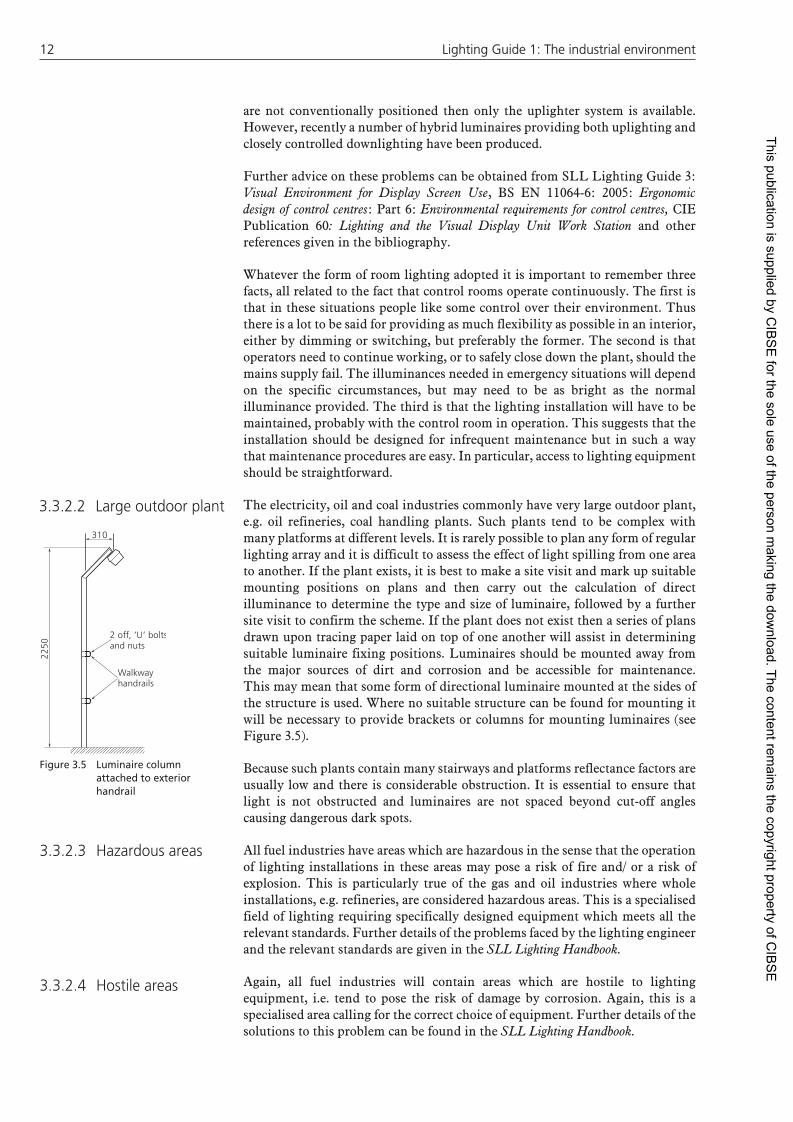
The electricity, oil and coal industries commonly have very large outdoor plant, e.g. oil refineries, coal handling plants. Such plants tend to be complex with many platforms at different levels. It is rarely possible to plan any form of regular lighting array and it is difficult to assess the effect of light spilling from one area to another. If the plant exists, it is best to make a site visit and mark up suitable mounting positions on plans and then carry out the calculation of direct illuminance to determine the type and size of luminaire, followed by a further site visit to confirm the scheme. If the plant does not exist then a series of plans drawn upon tracing paper laid on top of one another will assist in determining suitable luminaire fixing positions. Luminaires should be mounted away from the major sources of dirt and corrosion and be accessible for maintenance. This may mean that some form of directional luminaire mounted at the sides of the structure is used. Where no suitable structure can be found for mounting it will be necessary to provide brackets or columns for mounting luminaires (see Figure 3.5).
Because such plants contain many stairways and platforms reflectance factors are usually low and there is considerable obstruction. It is essential to ensure that light is not obstructed and luminaires are not spaced beyond cut-off angles causing dangerous dark spots.
All fuel industries have areas which are hazardous in the sense that the operation of lighting installations in these areas may pose a risk of fire and/ or a risk of explosion. This is particularly true of the gas and oil industries where whole installations, e.g. refineries, are considered hazardous areas. This is a specialised field of lighting requiring specifically designed equipment which meets all the relevant standards. Further details of the problems faced by the lighting engineer and the relevant standards are given in the SLL Lighting Handbook.
Again, all fuel industries will contain areas which are hostile to lighting equipment, i.e. tend to pose the risk of damage by corrosion. Again, this is a specialised area calling for the correct choice of equipment. Further details of the solutions to this problem can be found in the SLL Lighting Handbook.
3.3.2.2 Large outdoor plant
Figure 3.5 Luminaire column attached to exterior handrail
3.3.2.3 Hazardous areas
3.3.2.4 Hostile areas
310
2250
2 off, ‘U’ boltsand nuts
Walkwayhandrails
This publication is supplied by CIB
SE
for the sole use of the person making the dow
nload. The content remains the copyright property of C
IBS
E

Recommenda tions for interior lighting 13Recommenda tions for interior lighting 13
All lighting installations need maintaining, so lighting maintenance should be considered in every design. However, there are some areas in the fuel industry which pose particular problems of maintenance; a good example is the coal and ash handling areas of a power station and coal preparation plants. Lighting equipment capable of withstanding the associated conditions should be selected using the ingress protection classification system (see Section 5.2.1). Where hosing down is the common method of cleaning, luminaires of IP55 or better should be used. But this alone is not enough. By selecting the appropriate equipment, dirt and moisture can be prevented from entering the luminaire but the outside surfaces will still need to be cleaned regularly. An essential prerequisite for good main tenance is easy access to the lighting equipment. Once access has been gained, the equipment can be cleaned.
Other relevant documents1. The Protection of Eyes Regulations 1974 (amended 1975). 3. BS 7028: 1999: Eye protection for industrial and other uses. 4. SLL Lighting Handbook.
Application Maintained illuminance (lux)
UGR limit
Minimum uniformity (Uo)
Ra
Ironmaking
Sinter plant: Plant fl oor 200 28 0.4 60 Mixer drum, fan house, screen
houses, coolers, transfer stations200 25 0.4 80
Furnace cupolas: General 200 25 0.6 80 Control platforms 300 — 0.6 80Conveyor galleries, walkways 50 28 0.1 40
Steelmaking
Electric melting shops 200 25 0.6 80Basic oxygen steelmaking plants: General 200 25 0.4 80 Convertor fl oor, teeming bay 200 25 0.4 80 Control platforms 300 — 0.6 80Scrap bays 150 25 0.4 80Metal forming and treatment ingot stripping, soaking pits, annealing and heat treatment bays, acid recovery plant
200 28 0.4 60
Pickling and cleaning bays, roughing mills, cold mills, fi nishing mills, tinning and galvanising lines, cut up and rewind lines: General 200 25 0.6 80 Control platforms 300 — 0.6 80Wire mills, product fi nishing, steel inspection and treatment
300 25 0.6 80
Plate/strip inspection 500 25 0.6 80Automatic plant: remote operation 50 28 0.4 20 with occasional manual operation 150 28 0.4 40 with continuous manual operation 300 25 0.6 80 Control room 500 16 0.7 80Control platforms 300 — 0.6 80Non-automatic plant: charging fl oor, pouring, shaking
out, cleaning, grinding, fettling300 25 0.6 80
Rough moulding, rough core making 300 25 0.6 80Fine moulding, fi ne core making 500 19 0.7 80Inspection 750 19 0.7 80Forges: General 300 25 0.6 80 Inspection 500 19 0.7 80
3.3.2.5 Maintenance
3.4 Metal manufacture
This publication is supplied by CIB
SE
for the sole use of the person making the dow
nload. The content remains the copyright property of C
IBS
E

1414 Lighting Guide 1: The industrial environment Lighting Guide 1: The industrial environment
Included under this heading is the manufacture of metals: aluminium, brass, copper, iron, steel, etc., and their manipulation into products by casting, rolling, drawing and annealing. For the lighting engineer these operations imply two conditions: heat and dirt. In some areas, such as furnace and casting bays, both of these conditions will be present. In others, including surrounding plant areas such as service roads, only dirt will be present. All lighting engineers working in these areas will need to remember these particular environmental conditions.
The general lighting solution for interior lighting in metal manufacture is high-bay industrial lighting, typically using high-intensity discharge lamps. However, metal melting sometimes requires accurate judgement of tem perature from the colour of the molten metal. This may be difficult under high-pressure sodium discharge lamps, so these light sources should be used with care. These installations have to be capable of operating at high temperatures, sometimes over 50 °C. Temperatures like this may occur anywhere but much higher temperatures occur close to furnaces. It is useless to attempt to mount luminaires near such localised ‘hotspots’, so the position of luminaires needs to be considered carefully in relation to the layout of the plant. Control gear should be mounted remotely from areas of high ambient temperature. However, care should be taken over the distance between the control gear and the lamp, particularly for igniter circuits. Manufacturers should be consulted about the maximum distance that is allowable.
The equipment used also has to be chosen with care. The installation will be expected to operate reliably over long periods with minimum maintenance. Control gear should be of substantial construction. It should offer maximum heat dissipation while preventing the ingress of dust. Similarly, luminaires should be of substantial construction and selected with care. Self-cleaning luminaires can usually cope with the volume of dust in such locations. However, any enclosed luminaire must be fitted with a gasket suitable for withstanding the temperatures found in the plant. The luminaires chosen should be capable of easy maintenance, because this will be required frequently. Finally, there should be little risk of parts of the luminaire becoming accidentally detached during maintenance. If all these require ments can be met and the installation can be laid out to ensure easy access for maintenance, then many of the problems of lighting for metal manufacture will be solved. However, there are a number of special problems that deserve consideration.
In many areas of plants used in metal manufacture, considerable numbers of overhead cranes are used. If high-intensity discharge lamps are used for the general lighting then there is a risk of the crane obstructing a significant part of the lighting in some areas. This can be alleviated by a staggered layout of luminaires or by fitting each crane with boom lights so that the crane carries some supplementary lighting with it. This configuration is shown on the front cover of this guide. All the comments about the conditions in which the high bay lighting has to operate apply to such boom lights, as well as the need to consider the effects of vibration. If vibration is likely to be a problem, filament lamps should not be used. Screw cap discharge lamps withstand vibration better. If vibration is likely to be severe, anti-vibration mountings should be provided.
There are a number of operations in metal manufacture which call for detailed visual work and hence require higher illumination than those usually recommended for general movement. Such activities are re-lining furnaces, ladle inspection and building up stopping rods, devices which control the flow of metal from the ladle. Some form of localised or angled directional floodlighting may be needed in these areas.
Control areas and control rooms are now widely used in metal manufacture. A feature of these control rooms, which differentiates them from those discussed
3.4.1 Introduction
3.4.2 Lighting problems
3.4.2.1 Cranage
3.4.2.2 Local and localised lighting
3.4.2.3 Control areas and rooms
This publication is supplied by CIB
SE
for the sole use of the person making the dow
nload. The content remains the copyright property of C
IBS
E

Recommenda tions for interior lighting 15Recommenda tions for interior lighting 15
in the fuel industries, is that there is usually a view of the plant being controlled. In Figure 3.6 parabolic wedge luminaires have been set into the ceiling, these minimise reflections on the VDUs and the window, they also produce good horizontal illumination. Viewing through glass requires care because if the room surfaces in the control room are brighter than the surfaces of the plant area being controlled, reflections from the windows may be disturbing and distracting. Fitting the lighting installation in such control rooms with dimming facilities is desirable. Otherwise the problems of lighting control rooms are, again, those of ensuring adequate lighting on vertical planes and avoiding reflections from instrument panels and visual display screens. These problems can be overcome by the careful selection of lighting approach, luminaires and positioning.
Other relevant documents1. The Protection of Eyes Regulations 1974 (amended 1975). 2. The Clay Works (Welfare) Special Regulations 1948. 3. SLL Lighting Handbook. 4. BS 7028: 1999: Eye protection for industrial and other uses. 5. The Workplace (Health, Safety and Welfare) Regulations 1992.
Application Maintained illuminance (lux)
UGR limit
Minimum uniformity (Uo)
Ra
Concrete productsMixing, casting, cleaning 200 28 0.4 40
PotteriesDrying 50 28 0.4 20Preparation, enamelling, rolling, pressing, shaping, glazing, fi ring
300 25 0.6 80
Engraving, colouring 750 16 0.7 80Hand painting, precision work a 1000 16 0.7 90
Notes:a Lamp CCT should be between 4000 K and 6500 K
In this context, ceramics includes concrete, pottery and glass and covers a wide range of products. The products of the ceramic industry are put to a vast range of uses from window glass to sanitary ware, from works of art to specialised scientific equipment.
The lighting of areas used in the production of concrete does not pose any particular problems to the lighting engineer provided care is taken with the selection of luminaires. The manufacture of concrete products tends to involve dust and water. Therefore robust luminaires that are protected against the ingress of dust and water are desirable (IP54 minimum).
Potteries vary greatly in size but they all have areas where considerable heat is produced. Care is needed to avoid positioning luminaires where they are likely to be damaged by heat. Mass produced pottery and porcelain does not pose any problem for the lighting engineer until the finished product is inspected, and then only a full appraisal of how and where the finished items are inspected will reveal the best approach. Much will depend on the value of the individual items
Figure 3.6 A metal manufacture control room
3.5 Ceramics
3.5.1 Introduction
3.5.2 Concrete products
3.5.3 Potteries
This publication is supplied by CIB
SE
for the sole use of the person making the dow
nload. The content remains the copyright property of C
IBS
E

1616 Lighting Guide 1: The industrial environment Lighting Guide 1: The industrial environment
produced and whether they are inspected individually. Generally this inspection will be to detect any non-uniformity in body shape, the quality of surface glaze coverage and the constancy of colour. The lighting engineer will usually advise that light sources of Colour Rendering Group 1A or 1B be used to assist the discrimination of colours, and that care should be taken to ensure that the illumination provided meets the specified illuminance values within the inspection area without discomfort glare or strong shadows.
Pottery and porcelain which is hand-crafted or painted presents rather more difficult problems for the lighting engineer. The uniform lighting, probably quite satisfactory and commonly provided for the general pottery production areas, is not appropriate for hand-crafted production. It is necessary to create conditions very close to those provided for most inspection lighting, for the inherent requirements that are present in the visual task associated with intricate hand painting and high-class individual glazing are accurate visual discrimination, colour discrimination, perception of fine detail and form, and possibly even matching of colours.
A high proportion of the most critical work is done with the workpiece held or supported at approximately 45° angle and at short visual range. As different features may be more effectively revealed by different lighting techniques it may be found that a number of identical luminaires, preferably using two light sources of different colour-rendering qualities and with separate switching and dimming facilities, under local operating control, is the most satisfactory and successful solution. An illustration of this type of lighting is shown on the front cover.
To increase the vertical illuminance on the task, the luminaires, which should be capable of full positional adjustment by the artist, will normally be require to be tilted parallel to the target plane.
There is to a large extent, a form of continuous visual inspection taking place as the artist works and appraises the results of this effort, but nevertheless some form of final inspection will be required prior to the finished product being packaged. The most suitable form of inspection lighting for any specific product can only be determined accurately by an on-site survey of the visual task involved. A separate inspection room is rarely possible, but with individually created porcelain figures and china, an inspection booth of some kind may be appropriate.
Section 3.18 covers the principles of lighting for visual inspection. However, two techniques which are particularly useful in an inspection of ceramics are transmitted and reflected images of the light source. For translucent materials, such as porcelain with a diffuse surface, a light source positioned behind, below or within the product will create transillumination and hence reveal imperfections within the material itself. If the purpose of the inspection is to emphasise surface irregularities and the surface is strongly specular, an overhead local luminaire positioned to reflect the image of the source to the eye will reveal surface blemishes.
Application Maintained illuminance (lux)
UGR limit
Minimum uniformity (Uo)
Ra
Furnace rooms, bending, annealing lehrs, glass blowing, mixing rooms, forming,
300 25 0.6 80
cutting, grinding, polishing, toughening 750 19 0.7 80
Bevelling, decorative cutting, etching, silvering, engraving
750 16 0.7 80
Inspection, precision work, hand painting 1000 16 0.7 90 a
Manufacture of synthetic precious stones 1500 16 0.7 90 a
Notes:a Lamp CCT should be between 4000 K and 6500 K
3.5.4 Glassworks
This publication is supplied by CIB
SE
for the sole use of the person making the dow
nload. The content remains the copyright property of C
IBS
E

Recommenda tions for interior lighting 17Recommenda tions for interior lighting 17
It is only on the rare occasions when a new production plant specifically intended for glass manufacture is built that the opportunity is given to the lighting designer to provide a lighting system which is likely to create optimum visual conditions. Most lighting and visual problems encountered are to be found in existing glass making plants, but a great deal can and should be done to enhance these often onerous visual environments.
The term glass works conceals a wide divergence in visual needs and although the application of good lighting techniques at the ‘hot end’ of the plant, (the furnaces and glass making machine areas), are equally applicable to all glass making factories, the range of end products which leave those factories can differ greatly, from a sheet of plate glass to a delicately engraved wine goblet, from a milk bottle to a spectacle lens.
At the hot end of the glass process where heat and atmospheric pollution are excessive and plant machinery is large, it is customary to find mounting heights of 20–25 m available, thus a regular array of high-bay luminaires is the usual approach. The main problem is ensuring access for ongoing maintenance and lamp replacement as these luminaires are likely to be in the path of hot exhaust fumes created by extractor fans placed in the roof. The question of electrical maintenance must be studied in detail, for with active furnaces and molten glass being constantly on stream, it is virtually impossible to use conventional access equipment to reach the lighting equipment. Heat, height, dense occupation of floor space by cumbersome plant equipment, hot acrid fumes and pipework at intermediate heights above the floor make any unplanned maintenance routines extremely hazardous. Such are the onerous conditions found in this part of the works that prescriptive methods of lighting are often not practical. Only an on-site inspection will reveal what is possible at any particular plant.
Shadows created by large furnace plants can be a problem when considering the illumination of vertical surfaces. With excessive ambient heat levels and the usual design of furnace superstructure it may be advantageous to mount floodlights on the superstructure to light the surrounding vertical surfaces. In some areas, conventional high bay lighting may be ineffective as many of the floor areas are totally shielded from any overhead lighting. Then, additional lighting must be placed under platforms and canopies to enable work routines to be done in safety. These luminaires usually need to be cleaned very frequently and therefore need to withstand washing by pressure hose (IP55).
Some areas, for example, at the rear of furnace structures and machinery where timer mechanisms need to be adjusted when changes in a production run are required, can be exceptionally restricted in size and can be particularly dark. Some form of portable lighting is generally the most satisfactory solution but as cables are frequently severed by moving machinery or are completely burned by contact with hot metal surfaces whilst in use, low voltage operation through a step-down transformer is essential.
In all areas the lighting designer must pay full regard to safety of movement, to providing fast and accurate vision for operating valves and furnace controls and to ensuring that the lighting equipment used meets the safety and future maintenance problems associated with very hot, dusty and corrosive locations.
Packing and despatch areas are normally associated with the ‘cold end’ of the plant and generally these areas will be adequately served by standard industrial luminaires in a regular array. The design brief however must take into account the fact that even at the cold end dust and machine vibration can affect lamp and control gear life and luminaire performance. It is likely that there will be ample quantities of the chemical dusts created from the silicates, borates and phosphates which constitute the raw materials used in glass manufacture and can be expected
This publication is supplied by CIB
SE
for the sole use of the person making the dow
nload. The content remains the copyright property of C
IBS
E

1818 Lighting Guide 1: The industrial environment Lighting Guide 1: The industrial environment
to have a corrosive action on unprotected luminaires. Care should be taken to choose luminaires which will withstand onerous conditions.
A high proportion of decorative glass manufacture involves complex processes such as cutting, bevelling and etching. It is likely that supple mentary lighting of one form or another will be needed for these activities.
The essential characteristic of the supplementary lighting is that it should be adjustable by the operator, both in position and quantity. Care will also have to be taken with the surroundings of the working area to avoid specular reflections occurring in the workpiece; the geometry of a typical layout is shown in Figure 3.7.
Many of the techniques recommended for the visual inspection of specular materials may be appropriate with glass (see Section 3.18). Small items of glassware lend themselves ideally to directional lighting, where narrow beams of light aimed at oblique angles, or edge lighting techniques will produce excellent visibility of detail such as bubbles (seed), surface cracks (crizzles) and various forms of scratches, by creating areas of high luminance. Glass containers, particularly glass apparatus for the chemical laboratory, may require illumination from the base to show any imper fections within, and rear illumination to enable an inspector to check on symmetry or homogeneity by transillumination and, where appropriate, rotation (see Section 3.9.1).
Other relevant documents1. The Chemical Works Regulations 1922. 2. The Patent Fuel Manufacture (Health and Welfare) Special Regulations 1946. 3. The Highly Flammable Liquids and Liquefi ed Petroleum Gases Regulations 1972. 4. The Protection of Eyes Regulations 1974 (amended 1975). 5. SLL Lighting Handbook. 6. The Workplace (Health, Safety and Welfare) Regulations 1992. 7. BS 7028: 1999: Eye protection for industrial and other uses.
Application Maintained illuminance (lux)
UGR limit
Minimum uniformity (Uo)
Ra
Petroleum, chemical and petrochemical works
Exterior walkways, platforms, stairs and ladders
50 — 0.4 20
Exterior pump and valve areas 100 — 0.4 20Pump and compressor houses 150 — 0.4 40Process plant: remote operation 50 28 0.4 20 with occasional manual operation 150 28 0.4 40 with continuous manual operation 300 25 0.6 80 Control room 500 16 0.7 80
Figure 3.7 Principles for lighting of glassware
3.6 Chemicals
Lamp shieldedfrom view
Edge lightingof glass
Dark absorbentbackgroundeg black velvet
Lamp reflectionsdirected awayfrom eye
This publication is supplied by CIB
SE
for the sole use of the person making the dow
nload. The content remains the copyright property of C
IBS
E

Recommenda tions for interior lighting 19Recommenda tions for interior lighting 19
Application Maintained illuminance (lux)
UGR limit
Minimum uniformity (Uo)
Ra
Pharmaceutical and fi ne chemicals manufacture
Pharmaceutical manufacture: Grinding, granulating, mixing, drying,
tableting, sterilising, washing, preparation of solutions, fi lling, capping, wrapping, hardening
500 22 0.6 80
Fine chemical manufacture: Exterior walkways, platforms, stairs and
ladders50 — 0.4 20
Process plant 150 28 0.4 40 Fine chemical fi nishing 500 19 0.6 80 Inspection 750 19 0.7 80
Soap manufacture
General area 300 25 0.4 80Automatic processes 200 28 0.4 40Control panels 300 — —- 80Machines 300 25 0.6 80
Paint works
General 300 25 0.4 80Automatic processes 200 25 0.4 40Control Panels 300 — —- 80Special batch mixing 750 22 0.7 90 a
Colour matching 1000 16 0.7 90 a
Notes:a Lamp CCT should be between 4000 K and 6500 K
The chemical industry covers an enormous range of premises from large outdoor plant to clean rooms where the environment is carefully controlled. A common characteristic of chemical plants is the presence of a hazardous environment, (one in which the operation of the lighting equipment may represent a risk of fire or explosion), or a hostile environment, (one in which the lighting equipment is likely to suffer from corrosion). Advice on the standards applicable to and the selection of equipment for these conditions is given in the SLL Lighting Handbook.
Large outdoor chemical plants have much in common with the oil industry. The approaches discussed in Section 3.3 are therefore applicable.
Enclosed chemical plants have many features in common with heavy industry. Adverse environmental conditions may include heat, vibration, explosive gas/vapour mixtures and a corrosive atmosphere. There is likely to be considerable obstruction to any form of overhead lighting. Careful selection of lamps and luminaires to meet the environmental conditions is required as is careful positioning of them. Figure 3.8 shows the individual placing of luminaires around a hopper to provide the necessary task and access lighting. It may be necessary to provide additional lighting at some locations in the plant itself, particularly where there are control panels or where obstruction is excessive. If the plant is used for continuous production, there may be a separate control room. The options for lighting control rooms are discussed in Section 3.3.2. Supplementary lighting may be necessary for maintenance work on parts of the plant.
Plants for the manufacture of fine chemicals and pharmaceutical products are frequently hazardous and corrosive in nature and suitably certified corrosion-resistant luminaires must be used. In general, it is necessary to ensure that lamps are enclosed in any areas where the product is processed in open vessels. The installation should be designed to exclude cavities in or behind luminaires and
3.6.1 Introduction
3.6.2 Outdoor chemical plant
3.6.3 Enclosed chemical plant
3.6.4 Pharmaceuticals and fi ne chemicals
This publication is supplied by CIB
SE
for the sole use of the person making the dow
nload. The content remains the copyright property of C
IBS
E

2020 Lighting Guide 1: The industrial environment Lighting Guide 1: The industrial environment
associated wiring systems where dust and dirt can settle and infestation can take place. The equipment must be capable of easy and sometimes rigorous cleaning. This may require sealed luminaires of ingress protection rating IP54 to be recessed into or onto a membraned ceiling with the joints sealed with a suitable compound.
Attention must be given to the colour rendering of the light sources used to ensure consistent colour rendering of the product. If accurate colour judgements are required lamps of colour rendering groups 1A or 1B should be used (see Appendix 1).
Other relevant documents1. The Protection of Eyes Regulations 1974 (amended 1975). 2. The Horizontal Milling Machines Regulations 1928. 3. The Grinding of Cutlery and Edge Tools Regulations 1925 and 1950. 4. The Grinding of Metals (Miscellaneous Industries) Regulations 1925. 5. The Highly Flammable Liquids and Liquefi ed Petroleum Gases Regulations 1972. 6. SLL Lighting Handbook. 7. Protection Against Ultraviolet Radiation in the Workplace (National Radiological Protection Board.) 8. BS 7028: 1999: Eye protection for industrial and other uses. 9. The Workplace (Health, Safety and Welfare) Regulations 1992.
Application Maintained illuminance (lux)
UGR limit
Minimum uniformity (Uo)
Ra
Structural steel fabrication
General 300 28 0.4 40Marking-off 500 28 0.6 80
Sheet metal works
Pressing, punching, shearing, stamping, spinning, folding
500 22 0.6 80
Benchwork, scribing, inspection 750 22 0.7 80
Machine and tool shops
Rough bench and machine work 200 25 0.6 80Medium bench and machine work 300 25 0.6 80Fine bench and machine work 500 22 0.6 80Gauge rooms 1000 19 0.7 80
Die-sinking shops
General 500 22 0.6 80Fine work 1000 19 0.7 80
Welding and soldering shops
Gas and arc welding, rough spot welding 300 25 0.6 80Medium soldering, brazing, spot welding 500 22 0.6 80Fine soldering, fi ne spot welding 1000 19 0.7 80
Assembly shops
Rough work, e.g. frame and heavy machinery assembly
200 25 0.6 80
Figure 3.8 Individual placement of luminaires on a chemical platform
3.7 Mechanical engineering
Luminairespole mountedattached tohandrail
Luminairesmounted oncantileverbrackets
This publication is supplied by CIB
SE
for the sole use of the person making the dow
nload. The content remains the copyright property of C
IBS
E

Recommenda tions for interior lighting 21Recommenda tions for interior lighting 21
Application Maintained illuminance (lux)
UGR limit
Minimum uniformity (Uo)
Ra
Medium work, e.g. engine assembly, vehicle body assembly
300 25 0.6 80
Fine work, e.g. offi ce machinery assembly 500 22 0.6 80Very fi ne work, e.g. instrument assembly 750 19 0.7 80Minute work, e.g. watch making 1000 16 0.8 80
Inspection and testing shops
Coarse work, e.g. using go/no go gauges, inspection of large sub-assemblies
500 25 0.6 80
Medium work, e.g. inspection of painted surfaces
750 25 0.7 80
Fine work, e.g. using calibrated scales, inspection of precision mechanisms
1000 19 0.7 80
Very fi ne work, e.g. gauging and spraying and fi nishing
750 19 0.7 80
Inspection, retouching, matching 1000 19 0.7 80
Plating shops
Vats and baths 300 25 0.6 80Buffi ng, polishing, burnishing 500 22 0.6 80Final buffi ng and polishing 750 19 0.7 80
In sheet metal shops and machine rooms the choice of lamps, with respect to colour rendering, is generally not critical. However, care should be exercised in choosing light sources for non-ferrous metal working areas, as high-pressure sodium discharge lamps may reduce the contrast of surfaces such as brass and copper.
For sheet-metal shops, accurate scribing and setting out of metal work require freedom from strong shadows. This can be achieved by using a large number of closely spaced luminaires, each with a widespread distribution. The diffuseness of the lighting can be further enhanced by using relatively high reflectance surfaces in the shop.
The majority of machine shops contain rotating machinery, and although this is generally suitably guarded, it is sometimes necessary to gain access to the moving parts. This should be borne in mind when lighting these areas and selecting luminaire types. Special attention to stroboscopic effects is important. Light from discharge lamps can in certain circumstances cause rotating machinery to appear stationary or to be moving at a different speed than that at which it really is. Remedial measures to overcome stroboscopic effect are discussed in Section 2.9.
Where metal is being cut, the different levels of the material are best revealed by directional lighting which causes the newly cut metal to sparkle and produces a shadow of the cut, which is then easy to identify. Similarly, a drill bit may be more easily seen under directional light, the cutting edge having extra sheen. Directional lighting is best provided by a small directional luminaire attached to the machine. Ideally this lamp should be capable of being moved around the work as desired by the operator. An illustration of this type of machine lamp is shown on the front cover of this guide.
The revealing power of light when viewing complicated shapes can vary with the type of lighting used and the nature of the object to be seen. A cylinder head or similar concave and convex shape is best seen under a uniform general illuminance. Small objects such as screws can be better identified by directional lighting.
Generally, the information contained in Section 3.7.1 applies here. In welding shops, screens are used extensively and so considerable obstruction is likely. Where welding is carried out, portable lighting may be useful to light the workpiece.
3.7.1 Metal shops and machine toolrooms
Figure 3.9 Typical machine shop with roofl ights (photograph by kind permission of Hilclare Lighting)
3.7.2 Structural steel fabricating and welding/soldering shops
This publication is supplied by CIB
SE
for the sole use of the person making the dow
nload. The content remains the copyright property of C
IBS
E

2222 Lighting Guide 1: The industrial environment Lighting Guide 1: The industrial environment
The process of assembly can be divided into two separate and distinct types: small and large assembly. Assembly of small items which, when finished do not present a large obstruction, can be adequately illuminated by a regular array of luminaires.
In large assembly, the object being fabricated may create shadow hazards to other parts of the working area or parts of it may be in shadow. As the structure is assembled, the task plane may change drastically. Several levels of lighting may be needed, as may local portable lighting to compensate for illumination losses caused by the structure. Supplementary lighting may be required on the vertical plane.
Where large assembly is involved particular care should be taken to ensure a uniform illuminance, at the highest point of the building to which the eventual structure will go. It is sometimes advisable to under-space luminaires to achieve this uniformity. Alternatively, the use of directional floodlighting equipment mounted on the side walls may be preferred to increase vertical plane illuminance.
These shops are usually devoted to precise work. The illuminances provided are higher than generally used in the mechanical engineering industry. Care should be taken to ensure that the illuminance is provided uniformly without discomfort glare. A good approach is to use low luminance luminaires at close spacing. If accurate colour judgements are required lamps of colour rendering groups 1A or 1B should be used. Adjustable local lighting should be installed to allow individual workers to provide a directional element when and where it is needed. Figure 3.10 shows a car body inspection booth lit by fluorescent lamps behind flat opal panels to give a high illuminance on horizontal and vertical surfaces, with particular attention to the lower body panels. To reveal dents in body work the mirror images of luminaires are used and a portable spotlight is used to detect surface scratches.
The Highly Flammable Liquids and Petroleum Gases Regulation 1972 and Local Authority Regulations may apply to these areas. The lighting equipment should be of the appropriate standard for the paint type being used. Therefore it is necessary to know the hazard classification of the area and/or paint material and reference may be necessary to the above regulations and local authorities. More detailed advise is given in the SLL Lighting Handbook.
Lighting of these areas must be designed so that the illumination enables the operator of the booth to be able to see all parts of the object to be painted. Inspection normally takes place outside the booth. Inspection techniques are discussed in Section 3.18.
Where colour matching is required, care will have to be taken in the selection of the light source. Lamps of colour rendering index group 1A or 1B should be used (see Appendix 1). The choice of luminaires in these areas is very important. As well as complying with the relevant regulations, maintenance should be considered. It is advisable to mount the luminaires as high as possible away from the paint spray, to stop spray adhering to the luminaires. It may even be considered necessary to house the luminaires above some form of glass sub-ceiling structure which can easily be maintained (see Figure 3.11). If this is not possible, then a luminaire that is capable of being cleaned, with the necessary chemicals to remove the paint, should be chosen. It can sometimes be an advantage to use side lighting rather than overhead lighting. This gives two benefits. It increases the illuminance on the vertical plane and keeps the luminaires away from the paint spray.
The plating shop normally has an atmosphere of acidic fumes. Therefore, lighting equipment chosen must be able to withstand this corrosive atmosphere.
3.7.3 Assembly shops
3.7.4 Inspection and testing shops
3.7.5 Paint shops and spray booths
Figure 3.10 A car body inspection booth
Figure 3.11 A paint spray booth
3.7.6 Plating shops
Removableopal panel
This publication is supplied by CIB
SE
for the sole use of the person making the dow
nload. The content remains the copyright property of C
IBS
E

Recommenda tions for interior lighting 23Recommenda tions for interior lighting 23
Luminaires should be of the enclosed type and if metal, should be substantially constructed and finished to avoid corrosion of the luminaire and the electrical contacts therein.
For ease of maintenance the luminaires should be mounted around the edge of the large plating tanks. This serves two purposes: access is easy and the luminaire is out of the path of direct rising acidic fumes.
The general process of plating is to deposit a coating of one metal onto another metal sample. The evenness of the coating and colour will need to be inspected. Suitable inspection techniques are discussed in Section 3.18.
Other relevant documents1. The Electricity at Work Regulations 1989. 2. The Wireless Telegraphy (Control of Interference from Fluorescent Lighting Apparatus) Regulations 1989. 3. The Protection of Eyes Regulations 1974 (amended 1975). 4. BS 7028: 1999: Eye protection for industrial and other uses.
Application Maintained illuminance (lux)
UGR limit
Minimum uniformity (Uo)
Ra
Electrical equipment manufacture
Manufacture of cables, and insulated wires, winding, varnishing and immersion of coils, assembly of large machines, simple assembly work
300 25 0.6 80
Galvanising 300 25 0.6 80Coil impregnating 300 25 0.6 80Medium assembly, e.g. telephones, small motors 500 22 0.6 80Assembly of precision components, e.g. telecommunication equipment, adjustment, inspection and calibration
1000 16 0.7 80
Assembly of high precision parts 1500 16 0.7 80
Electronic equipment manufacture
Printed circuit boards: Silk screening 500 22 0.6 80 Hand insertion of components, soldering 750 19 0.7 80 Inspection 1000 16 0.7 80Assembly of wiring harness, cleating harness, testing and calibration
750 19 0.7 80
Chassis assembly 1000 16 0.7 80Inspection and testing: Soak test 300 25 0.6 80 Safety and functional tests 300 25 0.6 80
Electrical and electronic equipment manufacture involves very high quality of workmanship and control, often with very small components. Indeed, such is the demand for quality with the assembly of electronic components that quality control procedures and inspection may be almost a continuous part of the process of assembly.
The fabrication of components and assembly is usually carried out in open-bay, medium-height buildings. Large area, low-luminance luminaires with an indirect component can be used to advantage for the general lighting. Such luminaires will reduce the incidence of undesirable reflections in the task. Depending on the complexity of the equipment being manufactured, some form of adjustable local lighting may be of value.
In a typical electrical engineering workshop, work is not performed in every part of the workspace, but the tasks tend to be concentrated in certain areas. In such cases, it may be logical to limit the illuminance from the overhead general lighting and evaluate ways of introducing local directional lighting, which need not necessarily be machine mounted. General plus localised lighting schemes do require care if excessive contrasts in the field of view are to be avoided.
3.8 Electrical and electronic engineering
3.8.1 Introduction
3.8.2 Electrical equipment manufacturing
This publication is supplied by CIB
SE
for the sole use of the person making the dow
nload. The content remains the copyright property of C
IBS
E

2424 Lighting Guide 1: The industrial environment Lighting Guide 1: The industrial environment
Compact fluorescent luminaires may be particularly useful for localised use where precision assembly demands an increased illuminance. Wherever accurate colour judgements are required, e.g., for the selection of cabling, lamps of colour rendering groups 1A or 1B should be used.
High-precision work associated with the assembly of printed circuit boards, and particularly with the tasks of inspecting circuit continuity and the quality of soldered joints, requires a critical analysis of the visual task. The consequences of errors occurring after completion are likely to be serious and costly. The accuracy of colour judgement is an important factor in selecting the light source. In electronics assembly, multicored cables and components are used which are recognised by their colour identification. The colours enable the operative to identify and connect individual circuits and components. Typical examples would be distinguishing grey from silver, pink from beige, beige from amber or yellow, etc. Where such differences have to be seen, lamps of colour rendering groups 1A or 1B should be used.
For the assembly of printed circuit boards, satisfactory visual performance can be achieved using luminaires that provide an asymmetrical light distribution when they are suspended above but to each side of the area of work. Further improvements may be achieved by the addition of supple mentary lighting. How this additional illuminance is introduced will depend on the interior layout and orientation of work stations. Supplementary illumination can be provided by localised lighting, which in these circumstances should be adjustable by the operative, or the supplement may be achieved by the addition of a significant indirect component of illumination. This may be achieved very effectively by uplighter lum inaires. Light sources of high colour rendering index are recommended. If localised or uplighting techniques are used as supplementary to a general lighting arrangement it is important to ensure lamp colour compatibility. A technique for the inspection of printed circuit boards is discussed in Section 3.18.
Other relevant documents1. The Food Hygiene (Amendment) Regulations 1990. 2. The Herring Curing Welfare Order 1927 (Scotland 1926). 3. The Slaughterhouses (Hygiene) Regulations 1977. 4. The Milk and Dairies (General) Regulations 1959. 5. SLL Lighting Handbook. 6. The Workplace (Health, Safety and Welfare) Regulations 1992.
Application Maintained illuminance (lux)
UGR limit
Minimum uniformity (Uo)
Ra
Slaughterhouses
General 500 25 0.6 80Inspection 750 19 0.7 80Canning, preserving and freezing, grading and sorting of raw materials
500 22 0.6 80
Preparation 500 25 0.6 80
Canned and bottled goods
Retorts 300 25 0.6 80Automatic processes 200 25 0.4 80Labelling and packaging 300 25 0.6 80
Frozen foods
Process area 300 25 0.6 80Packaging and storage 300 25 0.6 80
Bottling, brewing and distilling
Keg washing and handling, bottle washing 200 25 0.4 80Keg inspection 300 25 0.6 80Process areas 200 25 0.4 80Bottle fi lling 500 25 0.6 80
3.8.3 Electrical equipment assembly
3.9 Food, drink and tobacco
This publication is supplied by CIB
SE
for the sole use of the person making the dow
nload. The content remains the copyright property of C
IBS
E

Recommenda tions for interior lighting 25Recommenda tions for interior lighting 25
Application Maintained illuminance (lux)
UGR limit
Minimum uniformity (Uo)
Ra
Edible oils and fats processing
Refi ning and blending 300 25 0.6 80Production 500 22 0.6 80
Mills
Milling, fi ltering and packing 300 25 0.6 80
Bakeries
General 300 22 0.6 80Hand decorating, icing 500 22 0.7 80
Chocolate and confectionery manufacture
General 300 25 0.6 80Automatic processes 200 25 0.4 80Inspection and packing 500 22 0.6 80
Tobacco processing
Material preparation, making and packing 500 22 0.6 80Hand processes 750 22 0.7 80
The aims of lighting in the food and drink industry are to enable the visual task to be carried out as easily as possible and to create a good working environment. The latter is particularly important since a bright, cheerful atmosphere is usually synonymous with cleanliness; a dull, dark environment can mean also a dirty environment, as dirt is certainly not easily seen in the dark. A good, cheerful environment can be created by using high-reflectance decorations coupled with a lighting scheme using luminaires with a wide-light distribution and a generous upward lighting component.
The food and drink industry covers a vast range of working areas, some of which are dusty, oil and fat-vapour laden, damp, corrosive and hazardous. The ambient temperatures can range from high (above 50 °C) to low (down to –30 °C). Care is therefore necessary in the selection of equipment.
Where the product is processed openly, the Food Hygiene (General) Regulations require that luminaires near the product be housed in an enclosure which prevents the lamp or any part of the luminaire accidentally falling into the product. The luminaires should be easily cleaned, main tained and re-lamped, and have the minimum horizontal surface area upon which dust can rest and have smooth lines and no crevices in which fungus can grow. They should have no loose parts which can accidentally become detached from the luminaire, and be constructed of materials with finishes which will withstand frequent cleaning and possibly hosing down (IP55 minimum), see Figure 3.12.
In designing schemes for the food and drink industry it is therefore essential to mount luminaires where they can be regularly maintained and preferably not directly over the product. Figure 3.13 shows luminaires mounted in the passageway, clear of the machines, in a roller grinder alley of a flour mill.
3.9.1 Food and drink industry
Figure 3.12 Easily maintained plant in food factory (photograph by kind permission of Hilclare Lighting)
Figure 3.13 Luminaire arrangements for a fl our mill
Luminairessuspendedbelowductwork
Window
This publication is supplied by CIB
SE
for the sole use of the person making the dow
nload. The content remains the copyright property of C
IBS
E

2626 Lighting Guide 1: The industrial environment Lighting Guide 1: The industrial environment
This gives access for maintenance and provides illumination through windows to the roller grinders.
The choice of light source can be important in areas where constant visual quality control is required, although it is generally sufficient to provide illumination from efficient light sources, and to use lamps of colour rendering group 1A only at quality control stations. Frequently, the illuminance at these points will be controlled to a constant level by a photocell and dimmer, and the time the lamp is in use monitored to ensure that the lamps are changed after the recommended burning hours.
In addition to the quality control check under the best colour-rendering lamps, a further check should be made under those lamps normally used for displaying the goods at the point of sale to ensure that the product is attractive to the purchaser.
As stated earlier, some areas may be hazardous. Distilleries of alcohol and essences have many such areas. Luminaires certified for use in areas where hazardous vapours and gases may be present should be used. Advice on the requirements of such luminaires is given in the SLL Lighting Handbook. In some areas, a hazardous environment may be present even though it is not obvious. This is particularly so in milling where certain concentrates of dust can be highly explosive. Reference should be made to BS EN 14034 and EU Directive 1999/92/EC for clarification as to the necessary precautions. Some companies have produced their own requirements which generally specify that the luminaires should be dust tight, as defined in BS 4533, and have a surface temperature compatible with the BASEEFA Type N, with a temperature rating appropriate to the dust ignition temperature. If there is any doubt it is wise to check if an area should be classified as hazardous.
The refining and blending of oils and fats are areas where fire or explosion hazards are obviously possible. This is coupled in some areas with a highly corrosive atmosphere.
Some sections of the food and drink industry are highly corrosive due to steam emitted from the preparation and cooking, or the cleaning and sterilising of containers. Slaughterhouses for example, tend to have highly corrosive atmospheres and in certain areas hosing down takes place, so the luminaires should be jet-wash proof (IP55).
It should be noted that there are statutory requirements covering lighting in slaughterhouses calling for general lighting of 200 lux and 500 lux in inspection areas, where lamps of colour rendering group 1A should be used.
Some food and drink factories where food products are refined or certain constituents are extracted resemble a chemical works, whereas others are similar to a laboratory. Nonetheless, the principles outlined in this section should be followed in all cases.
The packaging lines for food and drink have to be well lit, for although many of the packing lines use elaborate measuring devices, it is essential that a visual check can be carried out easily, as due to the speed of the packing process, any malfunction of the automatic control can involve high costs due to wastage (see Figure 3.14).
Bottling plants have particular inspection problems as the bottles have to be checked for cracks and where they are recycled they must also be checked for cleanliness. The check for cracks can be carried out with the bottles passing automatically through a booth with a low reflection background in which the
Figure 3.14 Conveyor in a bottling plant (photograph by kind permission of Thorn Lighting)
This publication is supplied by CIB
SE
for the sole use of the person making the dow
nload. The content remains the copyright property of C
IBS
E

Recommenda tions for interior lighting 27Recommenda tions for interior lighting 27
lighting is provided from above by fluorescent tubes (see Figure 3.15). It is worthwhile experimenting with tube colours as it has been found that inspectors have a preference for inspecting clear bottles under green fluorescent tubes. To inspect the bottles for cleanliness, the bottles should pass through a similar booth having a high reflectance matt background illuminated by white tubular fluorescent lamps (see also Figure 3.15).
Much of the selection and grading of the tobacco leaf is carried out prior to the product being received for processing at the plant. The tobacco arrives as a cake, in the form of a 600 lb, approximately 1 m cube of compressed tobacco leaf. This has to be conditioned and softened by steam and broken up. Maturity of the leaf, its general condition and grade, is judged primarily by colour. The illuminant best suited for this extremely critical colour judgement task is one similar to daylight from a clear northern sky. An illuminance of 500 lux, from a lamp of colour rendering group 1A with a correlated colour temperature of approximately 6500 K will produce satisfactory conditions.
Initial checking of the tobacco may occur when the product is in its compressed cake stage. The use of a portable trolley on which these colour matching lamps are mounted and which can be taken to the product may be found to be particularly useful.
Apart from any grading requirement, most seeing tasks in the tobacco industry can be illuminated satisfactorily by a general lighting system, provided the illuminance recommendations are met. This will even be adequate for the needs of experienced quality control inspectors who are seeking any tobacco leaf that has been affected by mould growth.
There is a possibility that with the dry leaf, dust can be a problem which needs to be considered in terms of maintenance of lighting equipment, but not necessarily as far as the provision of dust tight luminaires. Some of the hand processes may require supplementary task lighting.
Like some parts of the food and drink industry, the tobacco industry has a relatively substantial warehousing requirement, including bonded storage. It is likely that high pressure sodium sources will be eminently suitable for the warehouse areas and due to the need to establish a high-security environment it is considered essential that the lighting installation within the warehouse shall provide good illumination on all vertical surfaces as appropriate to the conditions and layout of the storage system. In addition, adequate security lighting is recommended for installation around the exterior, with particular emphasis being given to access points to the building (see Section 4.5).
Other relevant documents1. The Mule Spinning (Health) Special Regulations 1953. 2. BS 950: Artifi cial daylight for the assessment of colour. 3. SLL Lighting Handbook.
Application Maintained illuminance (lux)
UGR limit
Minimum uniformity (Uo)
Ra
Fibre preparation
Bale breaking, washing 300 22 0.6 80Stock dyeing, tinting 300 25 0.6 80
Yarn manufacture
Carding, washing, combing 300 22 0.6 80Spinning, roving, winding, plying, reeling 500 22 0.6 80Healding (drawing in) 1000 — 0.7 80
Fabric production
Knitting 500 22 0.6 80
Figure 3.15 A booth for the inspection of bottles
3.9.2 Tobacco industry
3.10 Textiles
Canopy housingfluorescentlamps
Dark matt backgroundfor inspection of cracks
Conveyor
This publication is supplied by CIB
SE
for the sole use of the person making the dow
nload. The content remains the copyright property of C
IBS
E

2828 Lighting Guide 1: The industrial environment Lighting Guide 1: The industrial environment
Application Maintained illuminance (lux)
UGR limit
Minimum uniformity (Uo)
Ra
Weaving Jute and hemp 300 22 0.6 80 Heavy woollens 500 22 0.6 80 Medium worsteds, fi ne woollens, cottons 750 22 0.7 80 Fine worsteds, fi ne linen, synthetics 1000 19 0.7 80 Mending a 1500 19 0.7 90 Inspection a 1000 16 0.7 90
Fabric fi nishing
Dyeing 500 22 0.6 80Calendering, chemical treatment etc. 500 22 0.6 80Inspection: ‘Grey’ cloth a 1000 — 0.7 90 Final a 1500 — 0.7 90
Carpet manufacture
Winding, beaming 300 22 0.6 80Setting pattern, tufting, cropping, trimming, fringing, latexing and latex drying
500 22 0.6 80
Designing, working, mending 750 22 0.7 80Inspection: General a 1000 19 0.7 90 Piece dyeing a 750 19 0.7 90
Hat manufacturing
General 500 22 0.6 80
Notes:a Lamp CCT should be between 4000 K and 6500 K
Textile manufacture, the turning of natural or man-made fibres into finished cloth, involves numerous processes which vary according to the raw materials used and the finishes required. Indeed, some of these processes can vary from factory to factory producing similar cloth. Careful analysis of the operations, particularly those involved in the preparation of the fibres, indicate that many are rough processes not involving an exacting visual task. Some others are completely automatic and the processing takes place inside a machine. In this case the lighting can only be regarded as giving amenity and safe access. In these areas a general overhead lighting system designed to give illumination throughout the area of the floors with increased illumination at the feed and take off ends of machines, as required, will be satisfactory.
The process of forming the yarn commences with the carding engines which form the staples into a loose rope. These machines are large and for the most part the process is enclosed. It is important to illuminate the feed and condenser ends of the engines and, for the sake of safety, the sides. Where the mounting height is restricted, luminaires placed over the cards would cause dense shadows on the sides, and in these circumstances it is best to place rows of dispersive type fluorescent tube luminaires over the gangways.
Following the carding, various other processes may take place in prepar ation prior to spinning. In all these processes the illumination recom mended should be provided in such a way as to ensure the elimination of dense shadows and as far as possible the penetration of light so that broken ends can be located easily. Bearing in mind that the operatives will be creating an obstruction, it is best to use luminaires with ‘simple’ light control systems and never to over space these luminaires.
Mule spinning, once common, has all but disappeared from the textile industry. Frame spinning in its various forms is now most used. The frames are usually tall with the task planes vertical and horizontal. The operative must be able to see the thread clearly from the point where it leaves the bobbin, down to the actual
3.10.1 Introduction
3.10.2 Yarns and fabrics
This publication is supplied by CIB
SE
for the sole use of the person making the dow
nload. The content remains the copyright property of C
IBS
E

Recommenda tions for interior lighting 29Recommenda tions for interior lighting 29
spinning spindle. It is difficult to state a universal correct way to illuminate the spinning room. It was thought that the best way was to run rows of fluorescent luminaires down the gates between frames which normally face each other, and certainly this can give excellent results. However, where space above the frames allows, a more economical layout is to run the fluorescent luminaires in continuous rows at right angles to the frames (note that in Figure 3.16, only the luminaires within angle h contribute directly to the illuminance at point A). In both systems the spacing between luminaires should not exceed the maximum spacing/mounting height ratio, and preferably they should be under spaced by up to one third.
Since the rows of spinning frames form corridors, the use of the lumen design formula to calculate illuminances is inappropriate and a method which includes only those luminaires contributing directly and indirectly to the illumination on the machines should be employed. Suitable methods are the aspect factor method for direct illuminance and the flux transfer method for the indirect component, as well as computerised design. Other machines such as twisting, doubling, winding, crimping, are similar in their lighting requirements to spinning frames.
Beaming or warping is the process of laying threads onto a beam or roller forming the warp prior to being placed on the loom for weaving. The thread of bobbins is placed upon a creel capable of taking hundreds of bobbins which are drawn through a reed which lays them onto the beam. It is essential that the operative should be able to see that all the ends are intact and that they are in the correct order.
Healding or drawing in, where done manually, is a most exacting visual task and the light must penetrate through the heald shafts so that the operator can distinguish the correct eye. A preference is for the general lighting to be supplemented by some local lighting which is portable and adjustable by the operative.
As for weaving, there are so many different types of looms and so many different types of fabrics that the lighting engineer’s first problem will be to find the correct category. Having done this, the recommended illuminance, lamp type, uniformity and unified glare ratio can be found. The next consideration is obstruc-tions. Whilst good general overhead lighting is usually preferred, overhead obstruction may necessitate a localised lighting approach. It is generally agreed that fluorescent luminaires in near continuous rows parallel with the warp give satisfactory results, particularly when placed over the shuttle boxes, giving good illumination on the threads and obviating shadows from the loom and the heald frames. Jacquard looms with overhead card systems can cause obstruction to a general lighting system necessitating a more localised approach.
Figure 3.16 Spinning frames forming a ‘corridor’ in a large area
A
θ
This publication is supplied by CIB
SE
for the sole use of the person making the dow
nload. The content remains the copyright property of C
IBS
E

3030 Lighting Guide 1: The industrial environment Lighting Guide 1: The industrial environment
The dying process is not one requiring a good colour matching light source since the actual matching and mixing of dyes is usually carried out visually in a separate room with specially constructed lighting booths, or by spectro chemical analysis. In the dye house, steam is usually present to a greater or lesser degree and the use of vapour-proof anti-corrosion luminaires may be required. Figure 3.17 shows the typical construction for an anti-corrosive fitting to IP 65, the body is generally made from glass fibre reinforced plastic and the diffuser can be either acrylic, or more typically polycarbonate. The diffuser clamps over a seal onto the body of the fitting. Whilst tubular fluorescent lamps are the most common light source used, in high buildings, high-pressure discharge sources have been used.
Finishing processes fall into two classes, wet and dry, the former necessitating the use of corrosion resistant enclosed luminaires. Some of the processes are hot, and therefore luminaires should be located away from the hot spots created above machines.
General overhead lighting systems within the areas are usually adequate providing they are supplemented by local or localised lighting of machines, and where necessary with luminaires directed inwards towards the cloth passing through, and at any inspection points.
Inspection and mending in the textile industry are very difficult tasks. Many different types of fault are possible and it is unlikely that any single system of lighting will be ideal for all of them. Variations in weave, slubs and foreign matter can be located by back lighting, (see Figure 3.18) with the cloth passing between a diffuse light source and the observer. Front lighting with a strongly directional component helps to reveal surface faults (see Figure 3.19). Generally, the use of lamps of colour rendering groups 1A or 1B is necessary to detect variations in woven colour patterns caused by the joining together of wrong broken warp threads by the weaver. However, it should be noted that to detect the difference between two similar colours it is sometimes helpful to distinguish both colours by showing them under strongly coloured light of a totally different colour.
The removal of foreign matter and mending usually takes place with operatives seated at a desk which may be sloping or flat with the cloth drawn over, and the faults made good by hand. This is a most exacting visual task, so it is necessary to provide a high illuminance (1500 lux) in a glare free manner and having good colour rendering properties. How this illumination is provided requires careful consideration, for while high illuminances provided by very diffuse lighting or by lighting, which is strongly directional normal to the surface of the cloth, may be good for some work, it does little to reveal the weave and texture of the material. It is therefore desirable to introduce some modelling by a directional component either by using an asymmetrical general lighting system, or by local lighting adjustable by the operatives.
Other relevant documents1. SLL Lighting Handbook.
Application Maintained illuminance (lux)
UGR limit
Minimum uniformity (Uo)
Ra
Leather manufacture
Work on vats, barrels, pits 200 25 0.4 40Cleaning, tanning and stretching, rubbing, cutting, fl eshing, stuffi ng
300 25 0.4 80
Finishing, scarfi ng, sorting, machine dyeing 500 22 0.6 80
Leatherworking
General 300 25 0.4 80Pressing, glazing, cutting, splitting, scarfi ng, sewing
500 22 0.6 80
Grading, matching a 1000 16 0.7 90
Notes:a Lamp CCT should be between 4000 K and 6500 K
Figure 3.17 Typical anti-corrosion fl uorescent fi tting
Figure 3.18 Back lighting of cloth
Figure 3.19 Front lighting of cloth
3.11 Leather industry
Cloth
Diffusing screenwith fluorescenttubular lamps
This publication is supplied by CIB
SE
for the sole use of the person making the dow
nload. The content remains the copyright property of C
IBS
E

Recommenda tions for interior lighting 31Recommenda tions for interior lighting 31
Leather is animal hide or skin that has been converted to a stable, non-putrescent state and made softer and more flexible by a series of processes of which the main one is tanning.
The tanning process involves salting and drying and although conventional general lighting from a regular array of luminaires is normally used, the designer has to select luminaires that are capable of withstanding hot, humid and salty conditions and position them so that they are not exposed to the worst conditions.
As for leather working, the prime visual problems are concerned with the selection and handling of the skin after delivery from the tannery. For the majority of activities, a uniform lighting installation is all that is necessary. However, the initial grading of the leather and final inspection of the product require special lighting. Satisfactory selection of skins has been achieved using north sky daylight but with the requirements of quicker and more continuous production in premises that do not permit the ingress of sufficient natural light, the use of artificial lighting has become important. For evaluating the evenness and density of skins a well diffused general lighting system using lamps of colour rendering group 1A is particularly desirable and a uniform illuminance is recommended. If glossy leather is to be examined, large area low luminance luminaires should be used. To search for blemishes in texture it may be necessary to provide a component of directional illumination. This may be achieved by omitting light from luminaires placed directly overhead and employing sources shielded from the direct view of the worker placed each side of the inspection table, thereby avoiding high luminance reflections in the leather. The surfaces of the bench which form the immediate surround to the work task should preferably be composed of colours having a high value and low chroma as classified by the Munsell system. Neutral light greys are suitable. To search for holes in the skin a light table can be used.
Other relevant documents1. SLL Lighting Handbook.
Application Maintained illuminance (lux)
UGR limit
Minimum uniformity (Uo)
Ra
Clothing manufacture
Preparation of cloth 300 22 0.6 80Cutting 750 19 0.7 80Matching 750 19 0.7 80Sewing 1000 19 0.7 80Pressing 750 22 0.7 80Inspection a 1000 16 0.7 90Hand tailoring a 1500 19 0.7 90
Hosiery and knitwear manufacture
Flat bed knitting machines 500 22 0.6 80Circular knitting machines 750 22 0.7 80Lockstitch and over-locking machines 1000 19 0.7 80Linking or running on 1000 19 0.7 80Mending, hand fi nishing a 1500 19 0.7 90Inspection a 1000 16 0.7 90
Glove manufacture
Sorting and grading 750 22 0.7 80Pressing, knitting, cutting 500 22 0.6 80Sewing 750 22 0.7 80Inspection a 1000 16 0.7 90
Hat manufacture
Stiffening, braiding, refi ning, forming, Sizing, pouncing, ironing
300 22 0.6 80
3.12 Clothing and footwear
This publication is supplied by CIB
SE
for the sole use of the person making the dow
nload. The content remains the copyright property of C
IBS
E

3232 Lighting Guide 1: The industrial environment Lighting Guide 1: The industrial environment
Application Maintained illuminance (lux)
UGR limit
Minimum uniformity (Uo)
Ra
Cleaning, fl anging, fi nishing 500 22 0.6 80Sewing 750 22 0.7 80Inspection a 1000 16 0.7 90
Boot and shoe manufacture
Leather and synthetics: Sorting and grading 1000 16 0.7 80 Clicking, closing 1000 22 0.6 80 Preparatory operations 1000 22 0.6 80 Cutting tables and presses 1000 16 0.7 80 Bottom stock preparation, lasting,
bottoming, fi nishing, shoe rooms1000 19 0.6 80
Rubber: Washing, compounding, coating,
drying, varnishing, vulcanising, calendaring, cutting
300 25 0.4 80
Lining, making and fi nishing 500 22 0.6 80
Notes:a Lamp CCT should be between 4000 K and 6500 K
Tailoring, garment making, and boot and shoe manufacture can all present demanding visual tasks involving fine detail, poor contrast and requiring accurate colour matching. The usual approach to lighting in the clothing and footwear industry is to provide uniform lighting with a good control of discomfort glare, complemented by adjustable local lighting or by fixed localised lighting. Accurate colour judgements are required in most of the work so lamps of colour rendering groups 1A or 1B should be used where practical. Colour matching of cloth is probably best done in a separate area specially designed for the work but with lamps of colour rendering group 1A and finished with neutral colour, medium reflectance surfaces. If local lighting is used it should be easily adjustable by the user but care should be taken to ensure that it does not cause discomfort glare either to the user or to others. It is advisable to consider that finished goods may be displayed under different lighting conditions from those in the factory and it is therefore wise to also inspect merchandise under the appropriate light sources.
Other relevant documents1. The Protection of Eyes Regulations 1974 (amended 1975). 2. The Woodworking Machines Regulations 1974. 3. The Highly Flammable Liquids and Liquifi ed Petroleum Gases Regulations 1972. 4. SLL Lighting Handbook. 5. BS 7028: 1999: Eye protection for industrial and other uses.
Application Maintained illuminance (lux)
UGR limit
Minimum uniformity (Uo)
Ra
Sawmills
General 300 25 0.6 60Polishing and painting 750 22 0.7 80Turning, fl uting, dressing, rebating, grooving, cutting, sawing and sinking
500 19 0.6 80
Grading, selecting veneers, marquetry and inlay work a
750 22 0.7 90
Quality control and inspection a 1000 19 0.7 90
Woodwork shops
Rough sawing, benchwork 300 25 0.6 80Sizing, planning, sanding medium machining and benchwork
500 19 0.6 80
Fine bench and machine work, fi ne sanding and fi nishing
750 22 0.7 80
Furniture manufacture
Raw materials stores 100 28 0.4 40Wood matching and assembly, rough sawing, cutting
300 25 0.6 60
3.13 Timber and furnishings
This publication is supplied by CIB
SE
for the sole use of the person making the dow
nload. The content remains the copyright property of C
IBS
E

Recommenda tions for interior lighting 33Recommenda tions for interior lighting 33
Application Maintained illuminance (lux)
UGR limit
Minimum uniformity (Uo)
Ra
Machining, sanding and assembly, polishing
500 19 0.6 80
Tool rooms 500 22 0.6 80Spraybooths: Colour fi nishing 750 22 0.7 80 Clear fi nishing 300 22 0.6 80Cabinet making: Veneer sorting and grading a 750 22 0.7 90 Marquetry, pressing, patching and
fi tting a
750 22 0.7 90
Final inspection a 1000 19 0.7 90
Upholstery manufacture
Cloth inspection a 1000 19 0.7 90Filling, covering 500 22 0.6 80Slipping, cutting, sewing 750 22 0.7 80Sewing 750 22 0.7 80Mattress making: Assembly 500 22 0.6 80 Tape edging 1000 22 0.6 80
Notes:a Lamp CCT should be between 4000 K and 6500 K
The visual approach to lighting in the timber and furniture industry is to provide uniform lighting from a regular array of luminaires.
However, there are a number of particular aspects of the industry which require attention from the lighting designer. The first is lighting maintenance. Dusty conditions are likely anywhere where timber is sawn, machined or otherwise worked. Dust-tight luminaires (IP 6X) are desirable in these areas. In extreme cases an explosion hazard may be present. Luminaires should be chosen appropriately. The second is the use of local lighting to highlight dangerous areas such as saw blades. Figure 3.20 shows the positioning of a lamp so that both light and shadow is used to indicate the position of the saw blade. The third is the possibility of stroboscopic effects occurring (see Section 2.7). The fourth is the need for lamps with good colour-rendering properties. The grading and matching of veneers and solid wood are good examples of activities where accurate colour judgement is required. In these locations lamps of colour-rendering groups 1A or lB should be used. In addition, some adjustable local lighting to provide directional effects may be useful in the grading of veneer timber. (For information on the lighting of spray booths see Section 3.7.5).
Other relevant documents1. Lighting in Printing Works (British Printing Industries Federation, 1980). 2. BS 950: Artifi cial daylight for the assessment of colour. 3. Protection Against Ultraviolet Radiation in the Workplace (National Radiological Protection Board, 1977). 4. SLL Lighting Handbook. 5. SLL Lighting Guide 3: Visual Environment for Display Screen Use.
Application Maintained illuminance (lux)
UGR limit
Minimum uniformity (Uo)
Ra
Paper mills
Pulp mills, preparation plants 200 25 0.4 80Paper and board making: General 300 25 0.6 80 Automatic processes 200 25 0.4 80 Inspection, sorting 500 22 0.6 80Paper converting processes: General 300 25 0.6 80 Associated printing 500 22 0.6 80
Figure 3.20 Lighting a saw blade.
3.14 Paper making and printing
Local lightplaced tothe side andin front ofblade
Scribe markclearlyshown
Edge ofbladehighlighted
Shadowindicateslengthof cut
This publication is supplied by CIB
SE
for the sole use of the person making the dow
nload. The content remains the copyright property of C
IBS
E

3434 Lighting Guide 1: The industrial environment Lighting Guide 1: The industrial environment
Application Maintained illuminance (lux)
UGR limit
Minimum uniformity (Uo)
Ra
Printing works
Type foundries: Matrix making, dressing type, Hand and machine casting 300 25 0.6 80 Font assembly, sorting 750 22 0.7 80Composing rooms: Hand composing, imposition and
distribution 750 19 0.7 80
Hot metal – keyboard 750 19 0.7 80 Hot metal – casting 300 25 0.6 80 Photocomposing – keyboard or setters 500 19 0.7 80 Paste up 750 16 0.7 80Illuminated tables – general: Lighting 300 19 0.8 80 Proof presses 500 22 0.6 80 Proof reading a 750 16 0.7 90Graphic reproduction: General 500 22 0.6 80 Precision proofi ng, retouching and
etching a
1000 19 0.8 90
Colour repro and inspection a 1500 16 0.8 90
Printing machine room:
Presses 500 22 0.6 80Pre-make ready 500 22 0.6 80Printed sheet inspection a 1000 19 0.7 90Binding: Folding, pasting, punching, stitching,
cutting, assembling, embossing 500 22 0.6 80
Notes:a Lamp CCT should be between 4000 K and 6500 K
Paper making is divided into two sections, wet end and dry end. The wet end involves the breaking up of the dry wood pulp and the mixing by rapidly rotating blades into a wet pulp in a vat. The pulp may be further beaten and other chemicals and colouring added. By nature of this process, these areas tend to be dusty, warm and damp, such that the dust coats all surfaces and is solidified by the humidity so that all hanging objects become festooned with stalactites which are dripping with water, eventually falling off. Therefore, within these areas the luminaires should be mounted so that they do not overhang the product but are positioned so that the insides of the vat are illuminated. The type of luminaire should be dust- and jet-proof (IP55 minimum), resistant to corrosion and easy to maintain.
The actual light source chosen and the distribution from the luminaire will depend on the room dimensions. In many cases these rooms are low, dismal areas. Therefore, luminaires with a widespread distribution and a generous upward lighting component are appropriate.
While it is in this area that the colours are added, it is not necessary to use lamps other than those normally used in industrial processes since the matching and mixing of the colorants usually takes place in a special colour matching booth (see Section 3.18). The slurry produced is fed into the open end of the paper machine and is first suspended on a continuous moving wire mesh known as ‘the wire’ which the operators view from both above and below to judge the even spread of the slurry which forms the web. Luminaires should not be mounted directly over the product but above and to each side, parallel to the machine, and positioned such that the illuminance is even over the length and width of the wire mesh. Further luminaires should be positioned at low level to illuminate below the top wire, Figure 3.21 shows the layout of the luminaires.
3.14.1 Paper making
This publication is supplied by CIB
SE
for the sole use of the person making the dow
nload. The content remains the copyright property of C
IBS
E

Recommenda tions for interior lighting 35Recommenda tions for interior lighting 35
The web passes through heated rollers or calenders on a felt. Frequently the calenders are covered by a canopy to extract the heat and humidity. It is most important to mount luminaires such that light penetrates between the rollers. This is usually achieved by using rows of fluorescent luminaires along both sides of the calenders suspended from or fixed to the canopy.
At the dry end of the calenders the paper is viewed from below for flaws, and at this point it is normal to illuminate this web with luminaires mounted directly above to show up any thin patches or foreign matter before passing to the finishing calenders and the final reel off.
Whilst tubular fluorescent luminaires are most appropriate for illuminating the machines, the surrounding area could be lit by high-intensity discharge sources.
Paper-cutting machines should be lit by fluorescent trough or angle reflector luminaires arranged in a localised scheme, mounted at both ends of the machine, with the sides at right angles to the rollers carrying the cutting blades, Figure 3.22 illustrates this arrangement. It is important to reduce any possible stroboscopic effects to a minimum. This may be achieved by using high-frequency control gear or by adjacent lamps being out of phase with each other, by having lamps fed from different phases of the supply (see Section 2.10).
The checking of sheets of paper takes place in a room named a salle. This requires lighting of good colour rendering and it is recommended that lamps of colour rendering groups 1A or 1B be used. To show up surface imperfections it is necessary to provide lighting with a moderately strong directional effect such as might occur in a room lit by large side windows. This effect can be achieved
Figure 3.21 Lighting ‘the wire’ in a paper mill
Figure 3.22 Localised lighting for a paper cutting machine
Angle luminairesto light betweenrollers of callender
Bulkheadsmountedbelow topwire
Wire
Side elevationEnd elevalion
Lighting directedat cutting blades
This publication is supplied by CIB
SE
for the sole use of the person making the dow
nload. The content remains the copyright property of C
IBS
E

3636 Lighting Guide 1: The industrial environment Lighting Guide 1: The industrial environment
artificially by a general overhead lighting system using luminaires with a medium to wide light distribution and fluorescent luminaires mounted on the benches. These bench mounted luminaires should be designed such that the light source is shielded from the inspector.
In the printing industry there are many tasks which demand the perception of fine detail and precise colour appraisal. Without lighting of the correct quantity and quality these tasks cannot be performed accurately.
The principal processes used in printing work involve letterpress, offset lithography and gravure. Letterpress is the process of printing from raised surfaces, inking rollers touching only the raised surfaces. Printing may be done on a flat cylinder press or rotary press which can handle continuous rolls of paper at high speeds. The lighting must take account of the need for the safe and efficient operation of all presses, but particularly the high-speed rotary presses which require rapid and accurate vision. Task lighting may be beneficial for the make-ready stage, as strongly directional light enables the strength of print impressions on the paper to be accurately judged and adjusted. Although very little monotype or linotype setting is now done by hand, there are occasions when this is used, and lighting needs in both strength and direction are also critical for this task.
Offset lithography involves the preparation of a litho’ plate and this includes photographic and chemical processes as well as the skilled re touching of half-tone pictures. Preferably, the lighting should be soft, diffused light of the recommended illuminance to restrict the formation of specular reflections from the plates. A system of uplighting luminaires may be appropriate. In some litho’ processes it is necessary to reduce the illuminance in areas where the sensitised plates can be affected by ambient light. In a few cases, it may be necessary to utilise photograph ‘safelights’ to which the plates are not sensitive. Alternatively, there is a sensitised coating used by some printers that may be handled at normal illuminances provided the only illuminant is the monochromatic low-pressure sodium lamp. Accurate photographic work is a major part of plate preparation, and the associated visual tasks are extremely demanding. Generally, the lighting units for the photography are furnished by the camera manufacturer. Stripping and opaquing are done on a large internally illuminated table. The table should afford the artist low luminance diffused brightness for visual comfort. The overhead lighting system would generally provide a low ambient level so arranged to eliminate any reflections in the table top. A form of uplighting could be used to good effect for this purpose.
A suitable level of luminance for the table has been found to be 500 cd/m2 within a room illuminance of 300 lux.
Gravure is the process of printing from sunken surfaces, and the printing surface is usually a copper cylinder. Gravure is used for fine quality work, such as stamps, banknotes, glossy magazines and mass circulation items such as colour supplements. Although the preparation of the cylinder is mainly photographic, some hand engraving is still done, and on many occasions hand alterations have to be effected upon the completed cylinder images when these are found to be defective in some way following a run on the proof presses. The fundamental problem is the discrimination of detail of the image on a curved metallic surface. Lighting from low surface brightness luminaires plus local task lights under the control of the engineer is essential. Specular reflections in the task can make intricate brushwork a most difficult visual task. Large area, low-luminance luminaires provide excellent contrast between the darker details of the photo image and the relatively lighter copper cylinder background, without much specular reflection.
3.14.2 Printing
This publication is supplied by CIB
SE
for the sole use of the person making the dow
nload. The content remains the copyright property of C
IBS
E

Recommenda tions for interior lighting 37Recommenda tions for interior lighting 37
A number of corrosive acids, flammable solvents and petroleum based inks, are widely used in all printing processes, so due consideration must be given to selecting luminaires appropriate to the level of risk of fire or explosion. Guidance is given in the SLL Lighting Handbook. Liaison with the Factory Inspectors at the Health and Safety Executive and/or the Fire Prevention Officer is recommended in these cases.
Ink haze can seriously pollute the atmosphere in some printing shops. It can affect the performance of luminaires by adhesion to both the lamps and the reflectors. It is difficult to remove without the use of a solvent which may also damage the luminaire. Depending on the degree of the problem encountered it may be beneficial to spray the luminaires with a protective agent before use and after each cleaning in order to prevent permanent adhesion of the ink haze.
Many machines are not fully guarded and protected against accidents. Guillotining, trimming, piercing, punching, slitting, embossing, numbering, folding, stitching, gluing and stapling are all necessary, and in many cases the settings must be arranged by time control. It is vital that lighting is organised to enable the operator to see what needs to be seen in preference to touch. The use of local or task lighting will be justified in many instances at vital points of such machinery as dark shadows and low contrasts can reduce the safety margins.
High-speed rotating machines require fast vision. Occasionally a stroboscopic effect is encountered and could cause problems. The possible solutions are discussed in Section 2.7. Multi-colour work demands that every consideration must be given to the choice of light source. Any reliance on daylight for colour appraisal is impractical, even during the long midsummer days. Tubular fluorescent lamps of correlated colour temperature 6500 K with a high colour rendering index (greater than 95) should be used for critical colour matching or appraisal. It is important that the recommended illuminance is maintained over the whole area where the visual task is being done. A special fluorescent lamp, Colour 47 (Graphica) is used for fine colour work and is incorporated into viewing cabinets of transparency viewers.
Other relevant documents1. The Chemical Works Regulations 1972. 2. The Protection of Eyes Regulations 1974 (amended 1975). 3. Protection Against Ultraviolet Radiation in the Workplace (National Radiological Protection Board, 1977). 4. SLL Lighting Handbook. 5. BS 7028: 1999: Eye protection for industrial and other uses.
Application Maintained illuminance (lux)
UGR limit
Minimum uniformity (Uo)
Ra
Plastic products
Automatic plant: Without manual control 50 28 0.4 20 Infrequent manual control 150 28 0.4 40 Continuous manual control 300 25 0.6 80 Control rooms 300 19 0.6 80 Control platforms 300 — 0.6 80Non-automatic plant: Mixing, calendaring, extrusion, injection,
compression and blow moulding, sheet fabrication 300 25 0.6 80
Trimming, cutting, polishing, cementing 750 19 0.7 80 Printing, inspection a 1000 16 0.7 90
Rubber products
Stock preparation, plasticising and milling 200 25 0.6 80Calendering, fabric preparation, stock cutting 500 25 0.6 80Extruding, moulding, cutting 500 22 0.6 80Inspection a 1000 16 0.7 90
Notes:a Lamp CCT should be between 4000 K and 6500 K
3.15 Plastics and rubber
This publication is supplied by CIB
SE
for the sole use of the person making the dow
nload. The content remains the copyright property of C
IBS
E

3838 Lighting Guide 1: The industrial environment Lighting Guide 1: The industrial environment
The lighting approach adopted for plants employed in producing plastics and rubber manufactures is little different from that used in industry in general. The usual approach is to provide a uniform illuminance over the whole plant area and to supplement it to a higher illuminance by local lighting as required. Locations where local lighting may be required are on control platforms and where inspection is undertaken. Portable lighting may also be useful for maintenance work on plants which are largely automatic.
The problems posed by plastic and rubber manufacture as far as the lighting engineer is concerned, are those of the environmental conditions. Plastics and rubber manufacture involves processes which may produce high ambient temperatures in some areas. Further, there can be a lot of dirt and dust in the atmosphere and the effect on lighting maintenance can be severe. To overcome these problems, light sources and control gear capable of operating at high ambient temperatures are desirable and dustproof (IP54) luminaires should be used. It should be noted that the light output of T12 and T8 fluorescent lamps reduces markedly at high ambient temperatures, but that of T5 linear fluorescent and high pressure discharge lamps does not. In addition to choosing dustproof luminaires it is good practice to arrange the layout of the luminaires so that they can be easily reached and maintained. This is particularly important in mixing areas where dirt and dust will be at a maximum level, so frequent regular maintenance is necessary.
Many plastics and rubbers are very dark or black in colour. These very low reflectances can cause problems in discerning detail, which calls for a much higher level of illuminance. Strong, directional lighting may be required.
Another characteristic of plastic and rubber manufacture is the obstruction to light distribution produced by the large pieces of plant used in the processes. Some plant may require lighting mounted on it if the operator is to see the work clearly.
Finally, where colour judgements are required, as in comparing plastic sub components, lamps of colour rendering groups 1A or 1B should be used, the surrounds should be neutral in colour and the inspection area should be shielded from the general interior lighting.
Other relevant documents1. The Chemical Works Regulations 1972. 2. SLL Lighting Handbook.
Application Maintained illuminance (lux)
UGR limit
Minimum uniformity (Uo)
Ra
Work Stores
Loading bays 150 25 0.4 40Unpacking, sorting 300 25 0.6 60Large item storage 100 25 0.4 60Small item rack storage 300 25 0.6 60Issue counter, records, storeman’s desks 500 19 0.6 80
Warehouses and bulk stores
Goods storage where identifi cation requires only limited perception of detail
100 25 0.4 60
Goods storage where identifi cation requires perception of detail
150 25 0.4 60
Continuously occupied storage areas where identifi cation requires only limited perception of detail
200 25 0.4 60
Continuously occupied storage areas where identifi cation requires perception of detail
300 25 0.6 60
3.15.1 Introduction
3.15.2 Lighting problems
3.16 Distribution and storage
This publication is supplied by CIB
SE
for the sole use of the person making the dow
nload. The content remains the copyright property of C
IBS
E

Recommenda tions for interior lighting 39Recommenda tions for interior lighting 39
Application Maintained illuminance (lux)
UGR limit
Minimum uniformity (Uo)
Ra
Automatic high bay rack stores: Gangway: unmanned 20 — 0.4 40 Gangway: manned 150 22 0.4 60 Control station 150 22 0.6 80Packing and despatch 300 25 0.6 60Loading bays 150 25 0.4 40Storage rack face a 200 — 0.4 60
Cold stores
General 300 25 0.4 40Breakdown, make-up and despatch 300 25 0.4 40Loading bays 150 — 0.4 40
Notes:a Calculation to be made on the vertical surface, portable lighting may be used.
Warehouses and storage areas exist in many forms but basically fall into a combination of the following: floor storage, high- and low-level pallets, high- and low-level racking, small and large bins, manual and automatic self picking areas. The basis of lighting the above areas is discussed in detail in each of the following sections.
For bulk storage at floor level it is generally important to avoid dense shadows and to give a reasonable illuminance on vertical surfaces if the reading of identification marks, labels, etc., is frequently carried out. A suitable way of lighting such an area is to use a closely spaced overhead array of luminaires with a widespread distribution. Generally the wider the distribution is the higher the vertical illuminance will be. Alternatively, a combination of overhead and side lighting will achieve satisfactory results.
The main problem in lighting this type of area is to eliminate shadows and to get the light to penetrate into the bins. The problems associated with bin lighting can best be solved by rows of tubular fluorescent luminaires, with trough reflectors mounted just above bin height and forward of the bins, and the luminaires being mounted parallel to the rows of bins. One particular problem occurs where the bin racks are movable and close together or open up to form an access way. In these cases it is necessary to run the rows of luminaires in a continuous row at right angles to the movable bin racks. The rows should be spaced such that the cut-off angle of the luminaires does not cause shadows on the top bins. Figure 3.23 shows sliding racking designed so that the cut-off angle is aligned with the sides of the racks.
3.16.1 Introduction
3.16.2 Bulk storage
3.16.3 Items stored in bins
Figure 3.23 Luminaire positioning above racking
Fluorescent luminairesmounted on trunkingSpacing should not exceed: 2 × Ht
ton of cut-off angle
Spacing
Ht
Cut-offangle
Cut-offangle
This publication is supplied by CIB
SE
for the sole use of the person making the dow
nload. The content remains the copyright property of C
IBS
E

4040 Lighting Guide 1: The industrial environment Lighting Guide 1: The industrial environment
It helps considerably if the bins are painted light colours, as this assists in reflecting light into the bins, and reflecting light within the bins, which can be almost impossible to illuminate directly from any overhead lighting system.
The main problems encountered here are the varying task plane heights, the variable location of the pallet stacks and the potential glare presented to fork-lift truck drivers. The latter, who are mainly concerned with locating the forks of the truck in pallets, and the correct and even stacking of the pallets, frequently work looking up towards the luminaires. These problems can be solved by using low-brightness luminaires with a widespread distribution, under spaced with, and if possible, a degree of upward light coupled with high-reflectance surfaces in the upper roof area of the building structure.
In high-palletised narrow-aisle racking areas, the main problem is to get the required illuminance at floor level between the racks without too much light on the tops of the racks.
These areas have similar problems to those discussed in Section 3.16.4, i.e. varying task plane height, and glare to fork-lift truck drivers. It is good practice to light these narrow aisles with runs of tubular fluorescent luminaires with narrow distributions arranged along the aisles, if the luminaires are mounted above the racking. Figure 3.24 illustrates the principle. However, the lighting designer must be careful not to create unacceptably low-vertical illuminance on the racks, which is common with narrow beam ‘rack’ reflectors. A better method of approach would be to use traditional trough reflectors with the luminaires mounted at the height of the top of the racking. It is also desirable that luminaires should give some upward light. Again, giving the roof surface a high reflectance helps to diminish any discomfort glare.
3.16.4 Random high pallet storage
3.16.5 High palletised racking storage
3.16.6 Self-selection warehouses
Figure 3.24 Rack luminaires
Traditionaltwin-troughreflector atrack height
Rackreflector
15°
Traditionaltwin-troughreflector
Rack Aisle Rack Aisle AisleRack Rack
For mounting heights above 15 m, high-intensity discharge lamps may be used in luminaires with a narrow transverse distribution and a wide axial distribution. The spacing of these luminaires should be such as to avoid the triangular dark areas which sometimes occur between luminaires (see Figure 3.25). This can be avoided in many instances by using low bay luminaires mounted at right angles to the run of the aisle.
Where self-selection takes place, the overhead lighting can be supple mented with luminaires mounted on the racking at low level to penetrate the bins. If this type of warehouse is fully automated, it is only required to give a low level of illuminance of about 20 to 50 lux, to provide safe access at floor level. Any maintenance work can be carried out using portable lighting as and where required.
This publication is supplied by CIB
SE
for the sole use of the person making the dow
nload. The content remains the copyright property of C
IBS
E

Recommenda tions for interior lighting 41Recommenda tions for interior lighting 41
Special attention must be given to cold stores because of the low temperatures involved. The lamps and luminaires should be chosen so that they can operate reliably in these conditions, the most common problems being starting and icing up. Advice on lamps suitable for low temperature operation is given in Section 6.4.3 of this guide as well as in the SLL Lighting Handbook.
Application Maintained illuminance (lux)
UGR limit
Minimum uniformity (Uo)
Ra
Staff restaurants, canteens, cafeterias, dining rooms, mess rooms
200 22 0.4 80
Servery, veg preparation, washing-up areas 300 22 0.6 80Food preparation and cooking 500 22 0.6 80Food stores, cellars 100 25 0.4 60First aid/sick bay 500 19 0.6 80Rest rooms 100 22 0.4 80Cloakrooms/toilets 200 25 0.4 80
Circulation areas
Lifts 100 25 0.4 40Corridors and passageways 100 28 0.4 40Stairs 100 25 0.4 40Escalators, travellators 100 25 0.4 40
Communications
Switchboard rooms 300 19 0.6 80Telephone apparatus room 150 25 0.4 80Telex room, post room 500 19 0.6 80Photocopier room 300 19 0.6 80
Building services
Boiler houses: General 100 28 0.4 40 Boiler front 150 — 0.4 40 Boiler control room 200 25 0.4 60
Figure 3.25 Dark triangular patches on racks caused by overspacing of luminaires
3.17 Ancillary areas
3.16.7 Cold stores
This publication is supplied by CIB
SE
for the sole use of the person making the dow
nload. The content remains the copyright property of C
IBS
E

4242 Lighting Guide 1: The industrial environment Lighting Guide 1: The industrial environment
Application Maintained illuminance (lux)
UGR limit
Minimum uniformity (Uo)
Ra
Control rooms 200 25 0.4 60Mechanical plant room 150 25 0.4 60Electrical power supply and distribution rooms 150 25 0.4 60Store rooms 100 25 0.4 60
This section is intended to deal with all the ancillary areas common to industrial premises, such as communication facilities, staff canteens, wash rooms, circulation areas, boiler houses, switch rooms, etc. Many of these areas can be lit by regular arrays of luminaires. However, some, such as reception areas, staff canteens and rest rooms benefit from a more imaginative approach to the lighting, aimed at creating the desired impression. For these situations the recommended illuminances should be treated as indicative only and the conventional illuminance uniformity requirements can be greatly relaxed.
The lighting of offices is beyond the scope of this document. General Guidance on the special problems posed by visual display units can be obtained from SLL Lighting Guide 3: Visual Environment for Display Screen Use and from the SLL Lighting Guide 7: Office Lighting.
The lighting of medical and first aid centres is also beyond the scope of this document. Guidance can be obtained from the SLL Lighting Guide 2: Hospital and Health Care Buildings.
In kitchens and serveries the comments given for the food industry generally will apply (see Section 3.9). Lamps and luminaires capable of operating in cold conditions or hot and humid conditions will be needed.
For circulation areas, such as corridors, stairs and escalators, the problem facing the lighting designer is that of positioning the luminaires. Linear luminaires should be orientated parallel to the corridors, unless some form of ceiling structure cuts off the view of the luminaire when it is positioned normal to the corridor. On stairs and escalators the luminaires should be positioned to provide a contrast between the treads and the risers. If the tread is made of specular material, care should be taken to avoid high luminance reflections from the tread towards anyone using the stairs or escalators.
Communications facilities, such as post rooms and photocopier rooms have few significant features as far as lighting is concerned. However, in telephone facilities, luminaires suitable for use with visual display units and other self-luminous information may be needed.
In boiler houses and switch rooms it is usually sufficient to use a small number of luminaires suitably placed around the boiler or switch panel. In switch rooms etc. care should be taken to provide some form of lighting at the rear of the cubicles, transformers, etc. to enable maintenance to be performed. Should the switch room, boiler house, control room, etc. have meters or gauges which are horizontal or vertical, special lighting will have to be considered, to avoid glare and reflections from them. Boiler houses usually have a high ambient temperature as well as large quantities of hot surfaces which radiate heat. In such areas, special thought will have to be given to the type of lamp and luminaire used, if short life of lamp and/or control gear is to be avoided. Discharge lamps generally will be better than tungsten or fluorescent in these areas, particularly if the gear is mounted remotely in some cooler area. Boiler houses and switch rooms are vital areas of any building and as with other areas, should be protected by standby or emergency lighting systems to enable quick action to be taken should it be necessary. Boiler rooms and storage areas have the possibility of containing inflammable material. It may be necessary to use flameproof luminaires in these areas. Document storage rooms and large walk-in safes containing vital files,
3.17.1 Introduction
Figure 3.26 Rest room with vending facilities (photograph by kind permission of JWA Services Ltd., Mansfi eld, and Hilclare Lighting)
3.17.2 Kitchens and serveries
3.17.3 Circulation areas
3.17.4 Communication facilities
3.17.5 Building services
This publication is supplied by CIB
SE
for the sole use of the person making the dow
nload. The content remains the copyright property of C
IBS
E

Recommenda tions for interior lighting 43Recommenda tions for interior lighting 43
documents, etc. will also benefit from enclosed flameproof luminaires as there is less chance of a fire developing from the luminaire.
In ducts that normally carry cables and pipes, if the duct is used continuously and the lighting is left on for long periods, the energy can be reduced by up to 75% and maintenance considerably reduced by using efficient luminaires with compact fluorescent lamps, LEDs or discharge lamps in suitable bulkhead luminaires. These areas are particularly suitable for integration with controls such as presence/absence detectors.
Visual inspection of products is an important aspect of many manufacturing processes. The accuracy of visual inspection is influenced by four aspects of the situation: the people, the task, the environment and the organisation. The people doing the inspecting are important because their visual capabilities affect the ease with which they can see the features of interest and their experience of the work will influence the way that they examine the product. The task is important in the way it is presented to the inspector. It can be presented for different periods of time, regularly or irregularly, stationary or moving, in ordered groups or individually, with different types of features occurring with different probabilities. The environment, which includes the lighting, is important because it affects the conspicuity of the features of interest. The organisation is important because it includes such aspects as the number and duration of rest pauses, the understanding the inspector has of what constitutes a feature that should be detected, the extent to which the inspector is kept informed of his performance and the relationship between the inspection and production sides of the business.
Thus the lighting of the product is only one of several factors influencing the accuracy of visual inspection; but it is an important factor and often it is one of the easiest to change. All too frequently the only concession made to the visual difficulty of inspection work is to provide a high illuminance in the inspection area. Although this is generally helpful, special lighting designed to reveal the critical features can be much more effective.
The aim of all inspection lighting is to increase the conspicuity of the features of the product that determine whether it is acceptable or not. There are a number of lighting techniques that can be used to achieve this aim, the choice between them depending on the nature of the material from which the product is made and the type of feature being sought. An outline of the main techniques is given below.
For flat materials with diffuse reflection characteristics where the features being sought are damage to the surface, e.g. scratches on a tile, the most effective technique is to light the material at a glancing angle so that no light is reflected towards the inspector’s eyes. The damage to the surface will be emphasised by the highlights and shadows created around it. Figure 3.27 shows the effect of glancing-angle lighting on the visibility of damage in cloth. It should be noted that glancing-angle lighting is very effective for revealing any form of texture on a surface, although whether this is an advantage or not depends on the particular circumstances; too much detail can be confusing.
For materials with specular reflection properties where the features being sought cause a change in the specular reflection pattern of the surface, e.g. scribe marks on stainless steel, there are two useful lighting techniques involving reflection. The first requires the reflection of a luminaire away from the observer. Then the damaged area will appear as bright on a dark background. The second requires the reflection of a luminaire towards the observer. Then the damaged area will appear as dark on a bright background. These differences occur in both cases because the damaged area scatters the light rather than reflecting it specularly.
3.18 Techniques of visual inspection
3.18.1 Introduction
3.18.2 Principles of inspection lighting
3.18.2.1 Controlling the direction of incident light
Figure 3.27 Directional lighting revealing damage in cloth
This publication is supplied by CIB
SE
for the sole use of the person making the dow
nload. The content remains the copyright property of C
IBS
E

4444 Lighting Guide 1: The industrial environment Lighting Guide 1: The industrial environment
For materials with specular reflection properties but where the feature being sought does not change the reflection characteristics but only the form of the product, e.g. a dent in a silver plated surface, a useful technique is to reflect a large area of low luminance from the product towards the inspector. Then, departures in form are revealed by non- uniformities in the luminance of the reflected image. The luminous area which is reflected from the product should be large enough to cover the whole product when viewed from the inspector’s position.
This technique is quite effective for dents which have a small radius of curvature (see Figure 3.28). However, where the dents have a large radius of curvature it will be advantageous to superimpose a regular grid over the large area of luminance. Then dents in the products will be shown by distortions in the reflected image of the grid.
With or without a grid, this technique depends on a non-uniformity in the image reflected from the product. Therefore this technique is only really suited for flat objects; more complex shapes produce too complicated a pattern of non-uniformities.
It should be noted that this technique of reflecting a large area of low luminance from a specular surface can be useful when it is necessary to separate a specular surface from a diffusely reflecting surface. For example, for examining the continuity of printed circuits, the reflection of a large area of low luminance towards the observer increases the conspicuity of the printed circuit from its background and reveals any breaks in it (see Figure 3.29).
Figure 3.28 Non-uniformity of luminance indicating dents
Figure 3.29 Refl ection of a large area of low luminance emphasises the detail on a circuit board
3.18.2.3 Transmission of light
Figure 3.30 Defect revealed by distortion of a background grid
Transmission of a large area of low luminance
For transparent and translucent materials where the features being sought are within the material, an effective technique is for the inspector to view a large area of low luminance through the object. Any bubbles, cracks, chips or foreign bodies will create non-uniformity in the transmitted luminance. Again the area of the low luminance should be sufficient to cover the product from the inspector’s position.
If the features being sought involve a change in form of the object it is useful to have a regular grid superimposed over the large area of low luminance. Then any changes in form create distortions in the regular grid as seen by the inspector (see Figure 3.30). Again this method is suitable only for objects of simple shape; complex shapes are likely to produce many distortions in the grid which will be confusing.
3.18.2.2 Refl ection of a large area of low luminance
This publication is supplied by CIB
SE
for the sole use of the person making the dow
nload. The content remains the copyright property of C
IBS
E

Recommenda tions for interior lighting 45Recommenda tions for interior lighting 45
Oblique transmission
For transparent materials, where the features being sought are bubbles, cracks, scratches, etc., another useful technique is to light the object with a strongly directional beam into the edge of the product so that no light reaches the inspector directly. Faults in the material will tend to produce scattered light which, when the object is viewed against a dark background, will appear as sparkling highlights. Figure 3.31 shows this technique being used for the inspection of moulded translucent glass.
3.18.2.4 Spectral com position of light
Figure 3.31 Oblique lighting aids the inspection of translucent products, such as glass containers
Clear or opal glass shelf
Low-reflectancebackboard
Translucent product under inspection
PAR lamp inlight-proof canister
Figure 3.32 An inspection booth for colour matching
Vertically adjustablescreen to suit inspector
Tubularfluorescent lamps
For many products, a common form of visual inspection is the examination of the colour of the product. For example, one of the criteria used to grade agricultural and horticultural produce is their colour. This form of visual inspection is called colour appraisal. The most important lighting variable for colour appraisal work is the spectral composition of the light source used. The lighting designer has two conditions to consider, (a) the light source under which the product will be used, (b) the light source under which the product will be sold. When these two light sources have similar effects on the colour of the product then the product need only be examined under one light source. However, if the using and selling conditions are markedly different, then inspection under both light sources may be necessary.
There is no single light source which is best for colour-appraisal work; the choice of light source is determined by the characteristics of the product and the colour appearance that is desired. For this reason, there is no substitute for practical experience when selecting appropriate light sources, although, in general, light sources with high CIE general colour rendering indices enable inspectors to make finer discriminations between hues. For colour-appraisal work the inspection area should be lit uniformly, without veiling reflections and to the recommended illuminance. The surroundings should be neutral in colour and of medium reflectance.
For some industries, such as printing and textiles, an important form of visual inspection is the matching of the colour of a product to an existing standard. Again the most important lighting variable available to the lighting designer is the spectral composition of the light source. BS ISO 3664: 2009 (supersedes BS 950) provides artificial daylight for the assessment of colour gives recommendations on the spectral composition of light sources suitable for accurate colour matching in various industries. In general, light sources with high CIE general colour rendering indices are most suitable for accurate colour matching. For colour-matching work the inspection area should be lit uniformly, without veiling reflections and to the recommended illuminance. The surroundings should be neutral in colour and of medium reflectance.
This publication is supplied by CIB
SE
for the sole use of the person making the dow
nload. The content remains the copyright property of C
IBS
E

4646 Lighting Guide 1: The industrial environment Lighting Guide 1: The industrial environment
A special aspect of colour matching is metamerism. This is the pheno menon whereby the colours of two products match under one light source but do not match under another. When this is likely to be important a check for metamerism can be carried out by examining the match between products under two light sources with widely different spectral compositions.
So far the lighting techniques considered have been those which use conventional lighting equipment to light the product and the naked eye to examine it. However, there are some inspection techniques which require unusual lighting equipment and/or some form of optical aid.
Polarised light can be used to examine the stresses within transparent products such as blown glass and moulded plastic. Light from an incandescent lamp is first polarised then transmitted through the product and finally analysed by another polariser. Stress in the transparent product changes the transmission pattern. Special apparatus is required for this type of work and the equipment usually includes the necessary lighting.
Many materials, including some lubricating and cutting oils, fluoresce in the presence of ultra-violet radiation, i.e. they produce visible light. This can be a useful aid in inspection. For example, by using a fluorescing dye, the security of a seal can be checked with ultraviolet radiation. Another possibility is to coat the surface of the product with a fluorescing material. Then when illuminated by ultraviolet radiation any hole will appear as black. To use this technique a suitable combination of fluorescing agents and an ultraviolet radiation source is required. Whenever ultraviolet radiation is used it is essential to consider precautions against excessive exposure of eyes or skin.
Some products are too small to be inspected by the naked eye. For such products some form of magnification is needed. This magnification can be achieved directly by viewing through a microscope or a magnifier. In either case the lighting required can be an integral part of the equipment provided.
Sometimes it is necessary to inspect moving parts whilst they are moving rapidly. Stroboscopic illumination can be used to apparently ‘slow down’ or ‘stop’ the movement of constant speed rotating or reciprocating machinery. To be successful the technique requires a very regular movement and very little illumination apart from that provided by the stroboscope. For safety reasons, whenever using this technique the operator’s attention should be drawn to the fact that although the machine is apparently moving only slowly or has stopped, it is actually still moving at the original speed.
The vast majority of visual inspection work involves looking for more than one feature in a product at a time. As different features may be most effectively revealed by different lighting techniques, this implies that visual inspection should be arranged sequentially with different lighting being produced for each stage. Rarely is this an economic proposition. Usually a compromise is required in which several different forms of lighting are provided at the inspection area and the inspector uses them as he thinks fit. This compromised approach will be most easily accomplished if the product is sufficiently small and lightweight for the inspector to manipulate it amongst the various lighting conditions himself. If this is not possible then sequential inspection lighting based on the most important features which need to be detected may have to be used.
Most inspection lighting techniques rely, for their effect, on creating conditions very different from those produced by the uniform lighting commonly provided in production areas. Therefore, if inspection lighting is to be effective, it either has to be much brighter than the production area lighting or it has to be separated from the production area lighting. A separate inspection room is rarely possible, but an inspection booth of some sort usually is. Figure 3.33 shows the design of
3.18.3 Practical aspects
3.18.3.1 Multiple defects
3.18.3.2 Separation from general lighting
3.18.2.5 Special techniques
This publication is supplied by CIB
SE
for the sole use of the person making the dow
nload. The content remains the copyright property of C
IBS
E

Recommenda tions for interior lighting 47Recommenda tions for interior lighting 47
an inspection booth for inspecting veneer pressings for flatness by using glancing angle lighting. Note the canopy shielding the inspector from the overhead lighting, and the pivoting mirror so that it can be set at a convenient angle for the inspector. The linear lamps should be fluorescent tubes with reflectors.
There is no substitute for the lighting designer being directly involved with the inspection task or at the very least, having available samples of the objects to be inspected which contain a representative collection of the features that need to be identified. Only then will the lighting designer be able to ‘tailor’ the lighting to the task.
Emergency lighting is provided to enable essential activities to be carried out in the event of the normal lighting failing for whatever reason. These essential activities can be divided into four types. The first, and most common, is to evacuate the area affected quickly and safely. This type of emergency lighting is called ‘escape lighting’. The second is to put machinery, plant or processors into a safe and stable state before evacuating the area. This type of emergency lighting is called ‘high-risk task-area lighting’. The third type of activity is where continuous operation is necessary during the failure of the normal lighting. This type of emergency lighting is called ‘standby lighting’. The fourth type is where large areas contain obstructions where evacuation could be difficult. This type of emergency lighting is called ‘open-area lighting’.
UK legislation imposes a duty on persons, including employers and other persons with control of premises, to carry out risk assessments and to take such precautions as to ensure as far as reasonably practicable the safety of the occupants. Guidance on risk assessments is given in PAS 79, in a series of guides published by Communities and Local Government, and in guidance published by the Justice Department of the Scottish Government. Equivalent guidance in Northern Ireland is currently in preparation.
Escape lighting is provided to ensure the safe and efficient evacuation of an interior. It must (a) identify the escape route clearly and unambiguously and the direction of movement along it, (b) illuminate the escape route to allow safe movement towards and out of the exit and (c) ensure that fire alarm call points, fire fighting equipment and safety equipment provided along the escape route can be readily located.
The standards usually adopted for escape lighting are specified in BS 5266, BS EN 1838 and in SLL Lighting Guide 12: Emergency Lighting. Neither of these documents are legal requirements. However, they can acquire legal status by reference. Although most enforcing authorities in the UK quote BS 5266: 2011, some modify the conditions. For example, they may insist on a higher illuminance. Therefore, the designer must thoroughly investigate the standards that will be applied.
Figure 3.33 Apparatus for directional lighting when inspecting veneer pressings for fl atness
3.18.3.3 The need for direct involvement
3.19 Emergency lighting
3.19.1 Types of emergency lighting
3.19.2 Escape lighting requirements
Veneer pressingunder inspection
Benchtop or roller conveyor
MirrorPivot
Line of linear lamps
Canopy to shield workpiecefrom overhead lights
This publication is supplied by CIB
SE
for the sole use of the person making the dow
nload. The content remains the copyright property of C
IBS
E

4848 Lighting Guide 1: The industrial environment Lighting Guide 1: The industrial environment
All exits and emergency exits must have exit or emergency exit signs. Where direct sight of an exit is not possible, or there could be doubt as to the direction, then direction signs with an appropriate pictogram are required. The idea is to direct someone who is unfamiliar with the building to the exit. All of these signs must be illuminated at all reasonable times so that they are legible. A typical emergency lighting layout for a small factory is shown in Figure 3.34. Note the exits are clearly marked with a luminaire outside the final exit; luminaires are placed at changes of level and direction, and are also adjacent to fire appliances and first aid points.
The minimum illuminance along the centre line of a clearly defined escape route should be 1 lux, and 50% of the route width for escape routes up to 2 m wide should be lit to a minimum of 0.5 lux. Gangways should be lit as clearly defined escape routes. Verified luminaire photometric data should be de-rated for end of battery and lamp design life, and allowance made for the effects of dirt and ignoring any reflections. It is important to note that most fires are accompanied by smoke, and that smoke may affect the illuminances produced on the escape routes.
The minimum illuminance should be exceeded at least one hour. Durations of three hours may be necessary in large complex premises, particularly where people unfamiliar with the site or of limited mobility may be present. One-hour duration systems are only suitable when the person responsible for carrying out the risk assessment can guarantee that persons will not be allowed back into the building until the emergency luminaires are fully recharged, this usually being 24 hours.
The emergency lighting luminaires should not cause problems of disability glare. Luminaires should be mounted at least 2 m above floor level in order to avoid glare but should not be much higher as they may become obscured by smoke. Luminaires should be located near each exit door and emergency exit door and at points where it is necessary to emphasise the position of potential hazards, such as changes of direction, staircases, changes of floor level and so on.
Fire-fighting equipment, fire-alarm call points and first-aid points along the escape route must be adequately illuminated at all reasonable instances. Although these may not be used in the event of fire, they should be illuminated. Emergency lighting is required in each lift car in which people can travel. Escalators must be illuminated to the same standard as the escape route to prevent accidents.
Figure 3.34 A typical emergency lighting scheme for small factory
Plant room
Privateoffices
Messroom
Toilet
First floorGround floor
Production area
Emergency exit sign
Exit signs
Emergency luminaires
Fire appliances
Stores
3.19.2.1 Marking the route
3.19.2.2 Illuminating the route
This publication is supplied by CIB
SE
for the sole use of the person making the dow
nload. The content remains the copyright property of C
IBS
E

Exterior lighting recom mendations 49Exterior lighting recom mendations 49
Emergency lighting luminaires are required in all control rooms and plant rooms. In toilets of over 8 m2 gross area, emergency lighting should be installed to provide a minimum of 0.5 lux.
High-risk task-area lighting is required in cases where machinery, plant or processors need to be brought to a safe and stable state before the area is evacuated. For such locations, the area should be illuminated to a minimum of 10% of normal illuminance. The emergency lighting may be needed for less time than is recommended for escape route lighting, the minimum duration being determined by an assessment of the time required to make the machinery or process safe.
After this period, the emergency lighting may be extinguished or the illuminance provided reduced depending on whether the area forms part of an escape route or not. Kitchens that prepare food should have emergency lighting to provide a minimum of 15 lux on the controls to allow safe extinction, in accordance with BS 5266: 2011.
For areas where continuous operation is needed throughout the period of failure of the normal lighting, standby lighting should be installed. The illuminance provided by standby lighting can vary from 5 to 100% of the standard service illuminance provided by the normal lighting, depending on the nature of the activities that need to continue. The correct lighting requirement can only be established by careful analysis of each situation.
Emergency lighting is required for open areas larger than 60 m2 or areas of any size with an escape route passing through them. BS EN 1838 requires 0.5 lux minimum anywhere in the central core of the floor area. This core area excludes the 0.5 m to the perimeter of the area. The shadowing effects of movable objects in the core area are also excluded.
There are numerous exterior areas associated with places of work, usually falling into three groups: working, access and storage. For all these areas the lighting must be designed to give a safe environment by revealing obstacles and hazards and be of a quantity and nature to enable efficient operation.
Application Maintained illuminance (lux)
UGR limit
Minimum uniformity (Uo)
Ra
Loading bays 150 25 0.4 40
The lighting of loading bays frequently pays little attention to the needs of the end user. For instance, it is pointless having a luminaire mounted under a canopy covering a loading bay door where a large vehicle can reverse up to the bay door and eliminate any possibility of the luminaire contributing useful illumination to any working area other than to the vehicle roof or the inside of the vehicle if the roof is translucent.
In bays with canopies 3–6 m above ground level, luminaires of IP23 or above should be used. Because of the possibility of sub-zero starting conditions it is better to restrict fluorescent tube lengths to 1500 mm for switch start circuits, although electronic and electronic start circuits can be used for any tube length. Ceramic metal halide and LEDs could also be used. There are special cold temperature luminaires designed to operate in sub-zero conditions.
3.19.3 High-risk task-area lighting
3.19.4 Standby lighting
3.19.5 Open-area lighting
4 Exterior lighting recommen-dations
4.1 Introduction
4.2 Loading bays
4.2.1 Introduction
4.2.2 Low canopy loading bays
This publication is supplied by CIB
SE
for the sole use of the person making the dow
nload. The content remains the copyright property of C
IBS
E

5050 Lighting Guide 1: The industrial environment Lighting Guide 1: The industrial environment
Luminaires should be so placed as to illuminate the areas to both sides of a vehicle as it reverses up to the loading bay door (see Figure 4.1); this allows the driver to place the vehicle wherever he needs without creating shadows and hazards. Figure 4.1 shows a typical layout of a fluorescent luminaire canopy mounted to illuminate as much as possible of the area between the vehicles and to facilitate unloading from the sides of the vehicles. Very deep canopies may require two or three luminaires per vehicle side in place of the single luminaire shown in Figure 4.1.
For canopies with heights greater than 6 m, as well as tubular fluorescent lamps, high-pressure discharge lamps and LEDs can be considered in the form of high-bay luminaires or floodlights with dispersive reflectors mounted on the canopy in a similar layout to Figure 4.1. If loading doors are further apart, the luminaires could be further apart to suit the vehicle use.
A further alternative for high canopies is the use of general purpose wide-beam floodlight luminaires with high-pressure discharge lamps or LEDs mounted in similar positions to high-bay luminaires or on the loading-bay walls (see Figure 4.2). When using high bay or floodlight luminaires, great care has to be taken so that undue glare is not caused to operatives, particularly vehicle drivers, as accidents could be easily induced. Always keep the peak beam of the floodlight out of the normal line of sight or light backwards to eliminate glare, as in Figure 4.3. Back floodlighting does not provide much lighting beyond the canopy edge, but will control light spillage effectively. However, the movement of shadows may help the driver to position the vehicle.
To help operatives see inside the vehicle and to assist with the task of loading and unloading it is sometimes beneficial to place one or more small wattage floodlight luminaires of the impact resistant type, on the loading bay door or on swinging arms on either side. If it is not a practical possibility then at least one floodlight should be mounted on one side aimed inside the rear of the vehicle. Two such units will produce a reasonably balanced environment to enable operative and fork-lift drive trucks to load and unload the inside of the vehicle. These floodlights should be switched on automatically when the loading bay is in use, and this can be done efficiently by using PIR or microwave movement detectors.
4.2.3 High-canopy loading bays
Figure 4.1 Correct luminaire positioning for a loading bay with low canopy
4.2.4 Lighting vehicle interior
This publication is supplied by CIB
SE
for the sole use of the person making the dow
nload. The content remains the copyright property of C
IBS
E

Exterior lighting recom mendations 51Exterior lighting recom mendations 51
Figure 4.2 Floodlighting luminaires for high-canopy loading bays Figure 4.3 Back-fl oodlighting for high canopies
Floodlight forlighting insideof van usedonly when vehicleis parked
Peak intensitybelow drivers sight
If the canopy has a stepped loading ramp under it (see Figure 4.4) then sufficient light should also fall on the ramp as well as between vehicles. It is less important in this instance which way the luminaires run, but generally the above guidance still applies. The edge of the loading bay should be delineated.
4.2.5 Stepped loading bays
Figure 4.4 Using light to mark the edge of a loading bayVehicleposition
4.2.6 Adjacent areas
4.3 Outdoor working and storage areas
Care should be taken to ensure that the illuminances in areas adjacent to the loading bay are not greatly different from that of the loading bay. For example, the ratio of the maintained illuminances in an interior storage area and on an adjacent loading bay should not be greater than 10:1.
Application Maintained illuminance (lux)
UGR limit
Minimum uniformity (Uo)
Ra
Short term handling of large units and raw materials, loading and unloading of solid bulk goods
20 55 0.25 20
Continuous handling of large units and raw materials, loading and unloading of freight, lifting and descending location for cranes, open loading platforms
50 50 0.4 20
This publication is supplied by CIB
SE
for the sole use of the person making the dow
nload. The content remains the copyright property of C
IBS
E

5252 Lighting Guide 1: The industrial environment Lighting Guide 1: The industrial environment
Application Maintained illuminance (lux)
UGR limit
Minimum uniformity (Uo)
Ra
Reading of addresses, covered loading platforms, use of tools, ordinary reinforcement and casting tasks in concrete plants
100 45 0.5 20
Demanding electrical, machine and piping installations, inspection. (use local lighting)
200 45 0.5 60
Area lighting is used to illuminate an open space, such as a car park or storage yard. Usually, the luminaires are mounted on poles along one or more sides of the area, but in cases of larger areas there may be a small number of lighting towers.
In this situation, two things can be done to help produce an economical area lighting scheme. First, the most efficient type of lamp should be used, noting that it is more economical to use a small number of large lamps than a greater number of small lamps. Second, it is more economical to trust to a group of luminaires on a single support than to mount each individually. Of course these ideas must be applied with discretion because the area of darkness is greater in the event of a fault. If the luminaires or clusters of luminaires are spaced too far apart relative to the mounting height, the lighting will be uneven and there will be dark patches which will make the installation ineffective for security purposes. The ideal arrangement is where every point in the area receives light in substantial proportions from at least two directions; this will reduce the shadows considerably. In general, the lower the mounting height of the lamps, the greater the likelihood of damage and the greater the degree of glare caused. Putting the lamps higher improves the spread of light, reduces light pollution and results in fewer lamps being needed. The mounting height should be related to the light output of each lamp (see Section 6.4.3).
Usually a lamp column or tower with its associated wiring is relatively expensive compared with the cost of a single luminaire. It therefore becomes logical to cluster two or more luminaires on a single column or mast, if this suits the lighting layout. The luminaires on a single stalk may face the same or different directions or might even be mounted at different heights.
As for spacing, the idea is to space the luminaires as far apart as possible whilst maintaining an acceptable uniformity ratio for the illuminance on the area. Typically a uniformity ratio of 40% is acceptable and achievable. Spacing the luminaires too far apart will result in pools of light with dark areas between in which it may not be possible to see what is happening. A typical layout showing spacing in terms of mounting height of the luminaires is shown in Figure 4.5, which can be used for either road lighting lanterns or floodlighting lanterns. As a rule of thumb, a spacing/mounting height ratio of 3:1 will be satisfactory for general lighting, although a greater ratio would be acceptable for security lighting only. It should also be noted that it is usually both glaring and inefficient to aim floodlights with symmetric reflectors at angles greater than 70° from the downward vertical. In addition, the resultant light pollution is unacceptable. The use of asymmetric reflector floodlights is recommended to help reduce light pollution, but care must be taken when aiming them.
If the area is so large that it cannot be illuminated by luminaires on columns or masts around its perimeter, it may be necessary to place additional columns or masts in the area (see Figure 4.6). An alternative approach for large areas is to use corner or central high-mast installations. High-mast installations typically have masts of 18 m or more, and can be similar to those found in sports arenas. Specific advice on high mast installations can be found in SLL Lighting Guide 4: Sports Lighting.
4.3.1 Introduction
4.3.2 Areas free from obstruction
This publication is supplied by CIB
SE
for the sole use of the person making the dow
nload. The content remains the copyright property of C
IBS
E

Exterior lighting recom mendations 53Exterior lighting recom mendations 53
In designing area lighting it must be appreciated that in some areas, such as lorry parks and container terminals, obstructions may cause long shadows and very dark areas. Increasing the mounting height in such a situation can dramatically reduce the size of the shadowed area.
Gantry yards are typical of many areas used for the storage of steel stock, iron, concrete pipes, bulk paper, etc. The area is divided into long narrow access and storage areas served by overhead travelling cranes. The stanchions supporting the gantry tracks can be used for mounting the floodlights which should be directed so as to illuminate each bay from both sides (see Figure 4.7). Although
Figure 4.7 Floodlighting gantry: stockyard
Floodlights mountedbelow line of sightof drivers cabfixed clear of crane lift
4.3.3 Obstructed areas
4.3.4 Gantry and crane yards
Figure 4.5 Typical layout for single fl oodlights
3 H 6 HH
Figure 4.6 Typical layout for placing additional columns
6 H
6 HH3 H
This publication is supplied by CIB
SE
for the sole use of the person making the dow
nload. The content remains the copyright property of C
IBS
E

5454 Lighting Guide 1: The industrial environment Lighting Guide 1: The industrial environment
crane rail heights vary, the luminaires should be mounted at about 6 or 7 m. Supplementary lighting should also be provided on the crane bridge. For this type of installation special attention has to be paid to the luminaire fixing arrangement, to ensure that it will withstand the vibration set up by the movement of cranes. Lighting each bay separately may be a good arrangement to enable energy savings to be made from switching, and avoiding obstruction.
In cases where operators have to move about on the tops of the stacks to handle stock or hoisting tackle or for other reasons, mounting height is particularly important and it may be necessary to add extension poles to the stanchions to obtain height to provide the illumination where it is required.
Bays where vehicle movements occur need supplementary luminaires mounted on columns or towers opposite the ends of the bays so as to illuminate these important loading areas without shadows. With the bay dimensions usually encountered, asymmetric floodlights are most applicable as they have a good general light distribution without wasteful upward light. The latter features may also help to restrict glare towards the crane. It should be noted though that this type of floodlight can generally produce less vertical illuminance.
Where access and working areas have to be illuminated between bulk tanks, the main problem is to get the light down to the necessary areas between the often tall tanks. Generally luminaires can be placed between the tanks, on columns, masts or even on the supporting steelwork of the tanks themselves. Care will have to be taken when siting the luminaires that long shadows or even dark areas are not created between tanks. A high mounting height and careful location, so that all areas are lit from two directions, will greatly alleviate this problem (see Figure 4.8). Some sites storing hazardous substances will require luminaires that are classified under the ATEX zoning scheme. Such circumstances will necessitate specific positioning of the luminaires in relation to the tanks and pipework.
4.3.5 Bulk tank storage
4.3.6 Large open stocking areas
Figure 4.8 Plan of tank farm lighting
CL
Additional floodlightsmounted on tankwill greatly reduceshadows
Tangent to two tanks fixes mastposition on centreline
Floodlightmast
The sort of areas which would fall under this heading are for instance, solid fuel stores at power stations and the mining industry. Generally in the coal industry the stocks are built up during the summer months and may rise to 6 or 9 million tons. Areas covered are large, and it is not unusual for land in excess of 10 000 m2 to be used. Tipping gives rise to a series of mounds and valleys that have to be created and levelled by mechanical means, i.e. bulldozers, mechanical shovels, etc. Vehicle headlights provide only strictly local illumination and as the surface is dark the luminance will be low. These exceptional conditions call for a technique which is rather different from normal floodlighting as the low reflectivity of the surround ings makes attempts to obtain an adequate bright visual field of medium to high luminance uneconomical. The alternative is to
This publication is supplied by CIB
SE
for the sole use of the person making the dow
nload. The content remains the copyright property of C
IBS
E
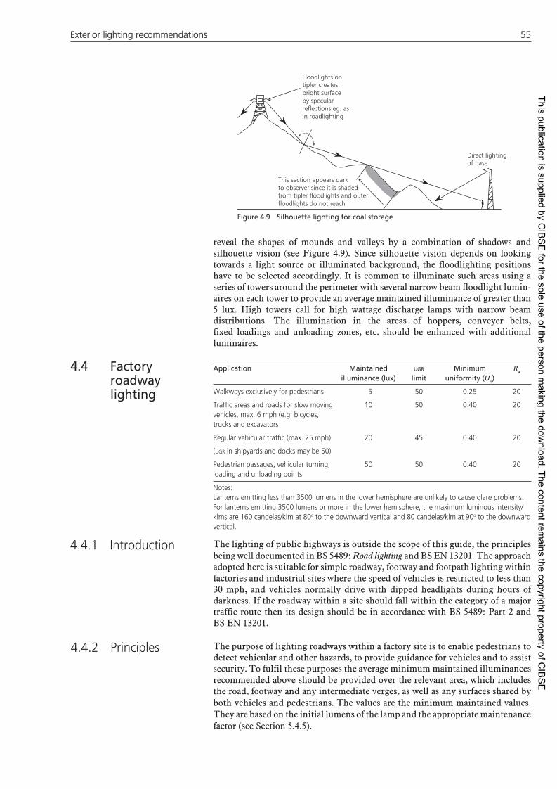
Exterior lighting recom mendations 55Exterior lighting recom mendations 55
reveal the shapes of mounds and valleys by a combination of shadows and silhouette vision (see Figure 4.9). Since silhouette vision depends on looking towards a light source or illuminated background, the floodlighting positions have to be selected accordingly. It is common to illuminate such areas using a series of towers around the perimeter with several narrow beam floodlight lumin-aires on each tower to provide an average maintained illuminance of greater than 5 lux. High towers call for high wattage discharge lamps with narrow beam distributions. The illumination in the areas of hoppers, conveyer belts, fixed loadings and unloading zones, etc. should be enhanced with additional luminaires.
Application Maintained illuminance (lux)
UGR limit
Minimum uniformity (Uo)
Ra
Walkways exclusively for pedestrians 5 50 0.25 20
Traffi c areas and roads for slow moving vehicles, max. 6 mph (e.g. bicycles, trucks and excavators
10 50 0.40 20
Regular vehicular traffi c (max. 25 mph) 20 45 0.40 20
(UGR in shipyards and docks may be 50)
Pedestrian passages, vehicular turning, loading and unloading points
50 50 0.40 20
Notes:Lanterns emitting less than 3500 lumens in the lower hemisphere are unlikely to cause glare problems. For lanterns emitting 3500 lumens or more in the lower hemisphere, the maximum luminous intensity/klms are 160 candelas/klm at 80o to the downward vertical and 80 candelas/klm at 90o to the downward vertical.
The lighting of public highways is outside the scope of this guide, the principles being well documented in BS 5489: Road lighting and BS EN 13201. The approach adopted here is suitable for simple roadway, footway and footpath lighting within factories and industrial sites where the speed of vehicles is restricted to less than 30 mph, and vehicles normally drive with dipped headlights during hours of darkness. If the roadway within a site should fall within the category of a major traffic route then its design should be in accordance with BS 5489: Part 2 and BS EN 13201.
The purpose of lighting roadways within a factory site is to enable pedestrians to detect vehicular and other hazards, to provide guidance for vehicles and to assist security. To fulfil these purposes the average minimum maintained illuminances recommended above should be provided over the relevant area, which includes the road, footway and any intermediate verges, as well as any surfaces shared by both vehicles and pedestrians. The values are the minimum maintained values. They are based on the initial lumens of the lamp and the appropriate maintenance factor (see Section 5.4.5).
Figure 4.9 Silhouette lighting for coal storage
Direct lightingof base
Floodlights on tipler createsbright surfaceby specularreflections eg. asin roadlighting
This section appears darkto observer since it is shadedfrom tipler floodlights and outerfloodlights do not reach
4.4 Factory roadway lighting
4.4.1 Introduction
4.4.2 Principles
This publication is supplied by CIB
SE
for the sole use of the person making the dow
nload. The content remains the copyright property of C
IBS
E

5656 Lighting Guide 1: The industrial environment Lighting Guide 1: The industrial environment
Further, both disability and discomfort glare need to be controlled to reduce light nuisance. The maximum luminous intensity per 1000 lumen criteria described above will ensure the necessary degree of control.
It is most important to remember when designing roadway lighting that the scene is viewed in horizontal perspective and not in plan. Rows of lanterns tend to lead users along the lines which they should follow. It is therefore essential that confused patterns are not created by badly sited lanterns which give the impression of roads continuing where they do not.
On the basis of luminous efficacy and life, light sources for roadway lighting on factory sites have generally been low-pressure and high-pressure sodium discharge lamps. Within many factory sites, recognition of people and objects frequently involves colour judgement. It is therefore better to use ceramic metal halide or LED lanterns rather than low-pressure sodium lamps despite the latter’s greater luminous efficacy, where pedestrian activities predominate. Current research is also showing that the effect of white light sources on mesopic vision can justify a reduction in required illuminance for both roadways and pedestrian areas.
In general, post, top or end support lanterns with or without integral control gear offer economic and aesthetic design solutions for factory roadway lighting. There are also good solutions to be found in the use of low level lighting on walls and posts. However, the exact choice of lantern will depend on the design criteria adopted, and the environmental conditions in which the lantern will have to operate, including whether or not the area is classified as safe or hazardous. The environmental conditions are important because they affect the degree of ingress protection (IP) needed by the lantern (see Section 5.2.1). The degree of IP of the lantern will have a considerable effect upon the maintenance factor which must be applied for the same cleaning interval. For example, a lantern with an IP23 rating may have a maintenance factor of 0.53, whilst a lantern with an IP54 rating could have a maintenance factor of 0.76, for a respective 12-month cleaning interval.
Another consideration is the choice of asymmetric reflectors against symmetric ones, to help reduce the effects of light pollution. The degree and type of atmospheric pollution can also affect the properties of some materials which are used in lantern construction. Aluminium alloys with high magnesium content should not be used in heavy industrial areas.
Many lanterns incorporate lamp control gear integrally mounted either in the lamp enclosure or a separate chamber. This system is particularly advantageous where lanterns are fixed to a building structure and also where individual control in the form of photocell and/or dimming is required, as the cabling is much simpler and maintenance is easier.
The mounting heights of lanterns will be governed to some extent by the required maintained illuminance over the relevant area, but there are also a number of practical aspects which should be considered. These are (a) the maximum height which can be reached by the maintenance equipment available on the site, (b) where it is not possible to erect columns the lanterns may have to be mounted on other structures and will therefore be restricted to the available heights, (c) hazardous area conditions at ground level may cause the mounting height to be increased so that the lantern with integral lamp control gear can be located in a safe area, and only the cable termination in the column base need be suitably certified, (d) overhead electrical supply cables will restrict the column height to give the safe clearance distance appropriate to the voltage carried.
4.4.3 Roadway lighting design
4.4.3.1 Light sources
4.4.3.2 Lanterns
4.4.3.3 Mounting height
This publication is supplied by CIB
SE
for the sole use of the person making the dow
nload. The content remains the copyright property of C
IBS
E

Exterior lighting recom mendations 57Exterior lighting recom mendations 57
A staggered arrangement of lanterns is preferred for most roadways but a single side arrangement may be used providing the design criteria are met. Lanterns should not restrict the passage of any vehicle likely to use the carriageway and should not project beyond the kerb. Columns should be mounted to give a clearance of 0.8 m from the surface of the column to the kerb, dependant on speed and safety barrier design. Bends and roundabouts should be lit by lanterns on the outside of the kerb but it may be necessary to place lanterns on the inside to meet the design requirements. Junctions should be treated with especial care. Pedestrian crossings should have a lantern placed just beyond the crossing from the approaching driver.
It must be noted that many factory roads are purely for access and small in length. However, some large factories have complex road systems which interconnect between different buildings, and may even have traffic control systems in operation.
It is advised that with any road lighting scheme BS 5489 should be consulted and the design advice therein followed, however small the access road may be. This will ensure that the lighting layout will match technically the road or street lighting adjacent to the factory site, and could save a debate between the factory and the local authority in the future.
Application Maintained illuminance (lux)
UGR limit
Minimum uniformity (Uo)
Ra
Very low risks, e.g. storage areas with occasional traffi c in industrial yards; coal fi elds in power plants; timber storage, sawdust and wood chip fi elds in saw mills; occasionally used service passages and stairs, waste water cleaning and aeration tanks, fi lter and sludge digestion tanks in water and sewage plants.
5 55 0.25 20
Low risks, e.g. general lighting in harbours; areas of risk free process and occasionally used platforms and stairs in petrochemical and other hazardous industries; sawn timber storage areas in saw mills.
10 50 0.40 20
(In harbours Uo may be 0.25)
Medium risks, e.g. vehicle storage areas and container terminals with frequent traffi c in harbours, industrial yards and storage areas; vehicle storage areas and conveyors in petro-chemical and other hazardous industries; oil stores in power plants; general lighting and storage areas for prefabricated goods in shipyards and docks; regularly used stairs, basins and fi lters of clean water plants in water and sewage plants.
20 50 0.40 20
(In shipyards and docks Uo may be 0.25)
High risks e.g. element mould, timber and steel storage, building foundation hole and working areas on sides of the hole at building sites; fi re, explosion, poison and radiation risk areas in harbours, industrial yards and storage areas; oil stores, cooling towers, boilers compressors, pumping plants, valves,manifolds, operating platforms, regularly used stairs, crossing points of conveyors, electric switch-yards in petro-chemical and other hazardous industries; switch yards in power plants; crossing points of conveyors, fi re risk areas in saw mills.
50 45 0.40 20
(At building sites and in saw mills GR may be 50)
Checkpoints 150 45 0.40 20
Gatehouses 200 (dimmable) 16 0.40 80
4.4.3.4 Arrangement
4.5 Security lighting
This publication is supplied by CIB
SE
for the sole use of the person making the dow
nload. The content remains the copyright property of C
IBS
E

5858 Lighting Guide 1: The industrial environment Lighting Guide 1: The industrial environment
The risk of a crime being committed is significantly higher at night than during the hours of daylight. Security lighting reduces this risk for two reasons: psychologically it acts as a deterrent to criminals who prefer to work under the cover of darkness, and functionally it allows security officers to see anything that may be happening in an area. Several factors affect the choice of lighting for security purposes: the economics of the situation, whether other security systems, such as closed circuit television (CCTV) surveillance are to be employed, the location of the lighting and the kind of premises being protected.
The primary principle of security lighting is to provide sufficient light over the protected area so that anyone moving in that area can be seen and preferably recognised easily. There should be no dark shadowed areas in which an intruder can hide.
Security lighting applications are many and varied; they range from the protection of a small rear door to the security of a large industrial stocking area, perhaps covering several thousand square metres. If CCTV is involved then the lighting criteria may be determined by the characteristics of the camera used, although it should always be remembered that ultimately if intruders are to be deterred then the possibility of active intervention by guards is necessary. This will require the illuminances recommended in order for the guards to be able to see the intruder adequately.
Where CCTV is used for security surveillance, the type of camera and system must be taken into account when designing the overall lighting system.
The type of camera can be primarily categorised as being either monochromatic (black and white pictures) or colour operation. Whilst the trend is to move towards high-definition colour cameras, there are still many sites using basic black and white units. Most cameras will now operate well at lighting levels below 1 lux, but the best definition pictures are obtained where higher levels greater than 10 lux are present.
CCTV systems also vary as to the complexity of their operation. More basic fixed systems use a single camera which is viewed by a security guard sat elsewhere in the building. Some advanced systems have time-lapse photographic principles to take one frame photograph every few seconds, which is then recorded. Other systems have multiple high definition cameras which can be focused and ‘zoomed’ in individually by security personnel positioned in a central control room. Some expensive cameras are capable of quality enabling face recognition and number-plate recognition of vehicles.
It must also be borne in mind that when colour cameras are used it is better to use a white colour appearance light source to be able to distinguish the colours, and whilst both low-pressure and high-pressure sodium lighting have been used successfully in the past with black and white cameras, this type of light source is best avoided where colour cameras are operated.
Most security lighting can be adequately provided by area lighting and roadway lighting as described in Sections 4.3 and 4.4. However, there are some areas which require special treatment.
Perimeter lighting is intended to enable security guards or police to detect anybody loitering outside a perimeter, which may be a fence or a building, or attempting to cross the fence or enter the building. Figure 4.10 illustrates suggested layouts for the security lighting of perimeters, including spacing, where H is the height of the luminaire and the spacing is 3 to 4 H. Street lighting lanterns, as shown, or floodlights and lanterns can be used.
4.5.1 Introduction
4.5.2 Principles
4.5.3 Perimeter lighting
This publication is supplied by CIB
SE
for the sole use of the person making the dow
nload. The content remains the copyright property of C
IBS
E

Exterior lighting recom mendations 59Exterior lighting recom mendations 59
A perimeter fence can be returned along the line of an entrance roadway and the space between the two facing lines of fence brightly illuminated. This creates a channel through which it is impossible to pass without being seen and will often stop unauthorised people even if there is no gate. Figure 4.11 illustrates a typical layout. At a gatehouse or vehicle checkpoint a convenient arrangement is to have local floodlights and a fence or a light-coloured wall extending for at least two vehicle lengths from the observation point and local lighting at lower level for checking vehicles and drivers papers. Sufficient light should penetrate horizontally to enable the inside of the vehicle to be checked adequately.
The interior lighting of a gate house should be shielded and subdued, and fitted with a dimmer. The idea is to prevent the gateman from being seen from outside, to ensure that his view is not hampered by bright reflections on the inside of the windows and to maintain his dark adaptation. The principles are illustrated in Figure 4.12. If the windows of the gate house are covered with wire mesh painted white outside or are made of very small glass panes with white painted glazing bars between, or if half-silvered glass is used, it will make it almost impossible for anyone to see in from outside, especially if the interior of the gate house is painted in dark colours. If there are windows on both sides of the gate house care should be taken that the gateman is not seen or silhouetted by other outside lighting. It should be impossible to tell from outside whether a gate house or security hut is occupied or not but the view from inside should be unimpeded.
4.5.4 Checkpoints
Figure 4.10 Street lighting lanterns and columns just inside the boundary fence Figure 4.11 Checkpoint lighting with
roadway entrance
Figure 4.12 Gate house lighting
Ceiling and upper wallspainted subdued colour
Wire mesh
Glazing tiltedto reducerelfections
Lamp on dimmershieldedfrom view
4.5.5 Gate houses
H
3–4 H
This publication is supplied by CIB
SE
for the sole use of the person making the dow
nload. The content remains the copyright property of C
IBS
E

6060 Lighting Guide 1: The industrial environment Lighting Guide 1: The industrial environment
Floodlighting a building or wall creates a bright background against which an intruder may be readily seen. If the district brightness is low, the thief standing in the space between the building and the floodlight projectors finds himself in a very difficult dilemma; going forwards towards the building will increase the likelihood of his being seen, yet to retreat towards the floodlights is dangerous for him as there may be police or security guards behind the glare of the lights. This approach is illustrated in Figure 4.13. In theory an intruder might decrease the chance of his being seen at night if he suitably camouflaged himself, for example, if he wore dark clothes and blacked his face. This might work if the building surfaces and the grounds were of the same reflectance but if the building and the area around it has a number of different reflectances such attempts at camouflage will be unsuccessful.
The floodlighting of buildings is described more fully in SLL Lighting Guide 6: The Outdoor Environment and the SLL Lighting Handbook. In the context of security it should be noted that floodlights mounted low or on the ground may be subject to damage or deliberate interference unless they are protected. In some situations, better revealment and lower cost will result from lighting building faces around an area rather than using area lighting. There may be publicity value in the floodlighting as well. However, care must be taken to keep light pollution low and not to contravene local authority planning requirements.
CCTV surveillance is a common security facility. The main role of lighting in such a facility is to allow the camera to produce a good quality picture. To do this it is essential to determine (a) the sensitivity of the camera to the wavelengths produced by the light source, (b) the minimum illuminance that will be required to produce good quality pictures, especially of moving objects, (c) the location of the camera, and (d) the area to be surveyed.
The spectral sensitivities of CCTV cameras are not the same as the human visual system, many being sensitive to infrared radiation as well as visible radiation. The choice of light source should take the spectral sensitivity of the camera into account.
Most manufacturers of cameras will indicate a minimum illuminance to be provided for the camera to operate successfully. However, if moving objects are to be successfully shown, an illuminance above the minimum should be provided. Care should be taken to provide the required illuminance evenly on all of the relevant surfaces. Some discrete cameras produce infrared images from infrared floodlighting mounted with the camera. These units can be used in darkness to detect intruders and then enabling manual or automatic switching on of the main visible lighting.
Ideally, the camera and the luminaires should be in the same plane. Where this is not possible the luminaires should be located so as to light the whole surveyed area uniformly. It is essential that the luminaires do not silhouette any object of interest nor should they point directly into the camera. The camera should not be able to see a light source or intensity that prohibits the camera from providing a correct image.
The area to be surveyed should be determined with care, particularly if the camera is of the motorised pan and tilt type. Only when the complete area to be surveyed is known will it be possible to select suitable positions for the camera and luminaires so that uniform lighting can be provided on all relevant surfaces and static highlights, e.g. direct sunlight, and moving highlights, e.g. vehicle headlights, can be avoided.
When designing a security lighting system for use with CCTV it is essential that guidance as to the characteristics of the CCTV system be sought from a competent
4.5.6 Floodlighting buildings
4.5.7 CCTV surveillance
Figure 4.13 Floodlighting
Floodlighting
Security hutBuilding
Wire fence
This publication is supplied by CIB
SE
for the sole use of the person making the dow
nload. The content remains the copyright property of C
IBS
E

Exterior lighting recom mendations 61Exterior lighting recom mendations 61
systems installer. It is also necessary to remember that the lighting installation has a role to play in security, independent of the CCTV system. A well-lit area will deter thieves and intruders and will enable anyone responding to the CCTV surveillance to see what is happening. A well-designed security lighting system should be capable of meeting the requirements of both people and CCTV cameras.
Application Maintained illuminance
(lux)
UGR limit
Minimum uniformity
(Uo)
Ra Remarks
Railway areas including light railways, tramways, monorails, miniature rails, metro, etc.
Avoid glare for vehicle drivers
Tracks in passenger station areas, including stabling, freight track, short duration operations 10a 50 0.25 20 U
d ≥ 1/8
Railway yards: fl at marshalling, retarder and classifi cation yards 10a 50 0.40 20 U
d ≥ 1/5
Hump areas 10a 45 0.40 20 Ud ≥ 1/5
Open platforms, rural and local trains, small number of passengers
15 50 0.25 20
Special attention to the edge of the platformU
d ≥ 1/8
Walkways, freight track, continuous operation, open platforms in freight areas, servicing trains and locomotives 20a 50 0.40 20 U
d ≥ 1/5
Level crossings, open platforms, suburban and regional trains with large number of passengers or inter-city services with small number of passengers 20 45 0.40 20
Special attention to the edge of the platformU
d ≥ 1/5
Railway yards handling areas 30 50 0.40 20 Ud ≥ 1/5
Coupling area 30 45 0.40 20 Ud ≥ 1/5
Stairs, small and medium-size stations, covered platforms, suburban or regional trains or inter-city services with small number of passengers
50a 45 0.40 40
Special attention to the edge of the platformU
d ≥ 1/5
Open platforms, inter-city services, covered platforms in freight areas, short duration operations
50 45 0.40 20
Special attention to the edge of the platformU
d ≥ 1/5
Covered platforms, suburban or regional trains, or inter-city services with small number of passengers
50 45 40 40
Special attention to the edge of the platformU
d ≥ 1/5
Covered platforms, inter-city services, stairs, large stations, covered platforms in freight areas, continuous operation
100 45 0.50 40
Special attention to the edge of the platformU
d ≥ 1/3
Inspection pit100 40 0.5 40
Use low-glare local lighting
Control rooms150 19 0.70 80
Use low-glare lighting
Goods depots: Container parking 10 50 0.25 20 Open cartage roads and forecourt 50 50 0.40 20 Transfer area 50 50 0.40 20 Shed deck 200 45 0.50 40
Notes:a Between tracks with rolling stock in positionU
d is the illuminance diversity representing E
min/E
max
4.6 Railways and Tramways
This publication is supplied by CIB
SE
for the sole use of the person making the dow
nload. The content remains the copyright property of C
IBS
E

6262 Lighting Guide 1: The industrial environment Lighting Guide 1: The industrial environment
In principle, sidings can be treated as examples of area lighting. However there are some features which deserve special attention. One is the presence of essential signals. These are of great importance when the lighting is being planned. The floodlight luminaires must not be positioned or directed so as to appear close to signals when viewed by an approaching driver. Apart from any confusion, glare can readily mask the light of the signal itself. Further, the floodlights should not be positioned so that reflections from the signal glasses give misleading impressions.
Careful placing of the lighting can greatly enhance the visibility of certain features such as the lie of points or the occupation of sidings when viewed from specific viewpoints. This is achieved by arranging for the light source, the track concerned and the viewpoint all to be roughly in line. This alignment takes advantage of the specular reflections from the polished surfaces of the rails to reveal them clearly.
The object of a marshalling yard is to receive trains of mixed wagons intended for many destinations, and to sort them out into several trains destined for particular towns or areas. The basic arrangement thus consists of a number of ‘roads’ (a track formed by a pair of rails is often referred to as a ‘road’) into which the wagons can be switched from a single sorting point (the ‘neck’). The smaller yards are usually flat and the wagons have to be moved by shunting engines. The larger yards on the other hand are normally of the hump type, in which the wagons are pushed up the hump at the neck, and run down by gravity over the points of their respective roads.
On arrival, the mixed trains are placed in reception sidings until they can be handled in the marshalling areas. The reading of the destination labels by the sorters involves the use of hand lamps as not only is this a comparatively fine visual task, but the labels are frequently on the lower framework and in shadow. On the other hand if the general lighting is properly arranged it is often sufficient for preliminary sorting; this is sometimes done by the recognition of label colours. For this reason monochromatic light sources such as the low-pressure sodium discharge lamp should not be used in these areas. When the destination of a wagon has been determined, the sorters put labels on the wagon ends, indicating to which road they are to be moved in the marshalling yard. Whilst in these sidings the wagons are checked by the wagon inspector, hand lamps are necessary for examination of the undercarriage and other parts of the wagon.
From the reception sidings the wagons are pushed through the neck and distributed to their various roads. Lighting of the hump or neck area is very important; operatives must have a clear view in both directions without glare, so that they can see the labelling on approaching wagons, the setting of the points, and the amount of clear track left in each of the train sidings. Viewed from the neck area, vertical-plane illumination also becomes important in assisting the identification of wagon markings, or judging the speed of approaching or receding wagons. In such cases illumination on the end of the moving wagon is essential.
In mechanised hump yards the speed of the wagons running into the different roads is controlled by automatic retarders, but in some older yards operatives known as ‘chasers’ have to apply the wagon brakes according to requirements. The lighting in this area has to reveal any spillage from trucks or other obstacles endangering the chasers, besides allowing them to perform their normal duties.
Consideration of the various factors discussed in this report suggests that a high-tower installation is usually more suitable for these large areas, besides having the advantage of less risk of confusion with signals. With properly sited towers the banks of lamps are normally well away from the line of sight of an engine driver on the main line, and are easy to recognise as a group of floodlights.
4.6.1 Sidings
4.6.2 Marshalling yards
This publication is supplied by CIB
SE
for the sole use of the person making the dow
nload. The content remains the copyright property of C
IBS
E

Exterior lighting recom mendations 63Exterior lighting recom mendations 63
Low-mounted lights tend to form a large and irregular pattern and it may not be easy to pick out a signal from its confused background of lights. Tower positions should be selected and placed as near as is practical to the higher illumination areas such as those around points, hump and neck. As mentioned above, as far as possible the floodlights should be directed along the tracks, but where the lighting has to be across occupied tracks, the results depend on reflections from wagon sides etc., and can only be considered effective up to a limiting angle of about 45° (see Figure 4.14). The lateral spacing thus depends on the height of the luminaires less the height of a wagon or coach. The maximum lateral spacing is obtained with the higher towers as the light coverage increases at a greater rate than the height. For example, if the height of a coach is 4 m and mounting height of the lighting 7.5 m, (see Figure 4.15) the maximum lateral spacing is 2 × (7.5 − 4) or 7 m. If the mounting height is increased six times, to 45 m, the lateral spacing can be increased to 2 × (45 − 4) or 82 m, or nearly 12 times.
Floodlight luminaires should be selected with care to avoid glare to operatives, the majority of light flux distributed from a floodlight should generally be contained within an angle not greater than 75° to the downward vertical, i.e. minimal light flux should fall outside the 75° (see Figure 4.16). Asymmetric reflectors can benefit the design and help reduce light pollution. Light spillage must be controlled in any circumstance and consideration must be given to the source intensity in high mast situations.
Figure 4.14 Maximum angle for effective lighting between wagons
Figure 4.15 Maximum lateral spacing
Figure 4.16 Limiting glare angle
Limiting angleTypical lightflux distribution
Peak beam
Max75°H
4.6.3 Goods depots
For areas involving the loading or unloading of containers onto trains localised lighting can be used effectively. For uncovered areas this could be achieved by lower wattage floodlights mounted at lower points on columns or towers. Covered areas can be lit using fluorescent, low-wattage discharge or LED sources usually in a symmetric array under the canopy. By using only a few fittings per circuit together with suitable controls, energy consumption can be kept to a minimum.
Normally goods depots consist of sidings for loading and unloading road vehicles and standing or berthing sidings.
The main concern is the loading and unloading area with its associated traffic space. Motor road systems within the yard should have road lighting, as specified in BS 5489: Code of practice for roadlighting and BS EN 13201.
For other areas, low- or medium-height installations, use broad beam asymmetric floodlights, or lantern type luminaires on columns or catenary wire. The layout and height employed naturally varying with the local conditions. All columns and catenary systems must give sufficient clearance for the manoeuvring of vehicles and movement of cranes, and be high enough for light penetration into open wagons. Penetration into the van type of wagon is naturally desirable, but this can be provided only to a very limited extent and is usually impractical as an excessively close spacing would be involved. Nevertheless, in loading yards, any bias in the direction of the lighting should be towards the loading side of the wagons. Where cranes are used see Section 4.3.4.
Max45°HM
HW
S
Hw
HM
S
S = 2(HM – HW)
This publication is supplied by CIB
SE
for the sole use of the person making the dow
nload. The content remains the copyright property of C
IBS
E

6464 Lighting Guide 1: The industrial environment Lighting Guide 1: The industrial environment
Application Maintained illuminance (lux)
UGR limit
Minimum uniformity (Uo)
Ra
General lighting of dockyard area, storage areas for prefabricated goods
20 55 0.25 40
Short term handling of large units 20 55 0.25 20
Cleaning of ship hull 50 50 0.25 20
Painting and welding of ship hull 100 45 0.40 60
Mounting of electrical and mechanical components
200 45 0.50 60
Container and bulk cargo terminals:
Loading/unloading areas 50 50 0.40 20
Stacking areas 20 55 0.25 20
Jetties 50 50 0.40 20
Quayside for general cargo 50a 50 0.40 20
Notes:a Care should be taken to provide a transition zone between the quayside and the associated warehouses.
Most modern docks are container based and use a series of cranes mounted along the quayside. Decisions concerning the lighting can only be satisfactorily resolved by separately considering each type of facility and evaluating the various areas which may present significant differences in visual tasks.
Container terminals involve cargo movement by rail or road. The highest illuminances are required at the quayside where the landing and hoisting originates and where the securing or releasing of chassis locking devices is likely to be part of the work. Bulk cargo is received by road or rail for loading aboard ship and is discharged from the vessels and transported away from the dockside by similar means. Typical cargo-handling devices include conveyer systems, gantry cranes, suction devices and powerful electromagnetic collectors. The highest illuminances are needed where the transfer of cargo from ship to road or rail and vice versa occur.
The lighting installation in all these areas has to satisfy certain primary requirements. It must not be allowed to produce glare to passing shipping or to navigators of vessels moving alongside. Neither must any columns, masts or towers, or individual luminaires obstruct or diminish the effect of navigational aids or signs. In practice, the avoidance of glare and harsh shadows is at least as important as the illuminance. However, terminals and docksides are vulnerable to unauthorised intrusion and theft can be a serious problem during the hours of darkness. Control of glare from the lighting system and the elimination of shadows will facilitate the task of visual supervision and the surveillance of the site.
Because large areas of land need to be kept clear to allow for the general movement of vehicles and cargo and the swinging loads of both fixed and travelling cranes, a useful approach is a high-tower floodlighting system. A high-tower installation has the great advantage of being able to light between stacked containers, cargoes and dockside buildings easily. These can present significant obstructions to the flow of light from floodlight situations where their mounting height above ground is a more traditional 8 to 20 m. The location of all high masts must be chosen with care to ensure the minimum physical hindrance to work and traffic flow within the area. Tower heights may be in the range 35 to 70 m. An illuminance of 30 lux covering the whole working area will normally be sufficient for crane operations. This illuminance can be provided by uniform area lighting or, if a lower illuminance is provided generally, supplementary lighting by floodlights attached to cranes and container-handling equipment may be used. However,
4.7 Dockyards, terminals, jetties and quays
4.7.1 Container and bulk cargo terminals
Figure 4.17 Typical quayside area (photograph by kind permission of the Belfast Harbour Commissioners and Hilclare Lighting)
This publication is supplied by CIB
SE
for the sole use of the person making the dow
nload. The content remains the copyright property of C
IBS
E

Equipment 65Equipment 65
it is recommended that such lighting should not be mounted on any section of a crane that rotates. Constantly moving patches of light with noticeably higher luminances than the ambient luminances may distract the attention of those working in the vicinity of the crane.
Jetties generally extend into the waterway and are usually a T-shaped structure. Because of the need to restrict glare to the surrounding waterway and to satisfy stringent navigational requirements it may be necessary to use louvred floodlights. Working conditions on a jetty, particularly if it handles oil or chemical cargoes, may be much more arduous than in the main harbour basin or container terminal. The need for good lighting is essential and if the area is classed as a hazard zone all locally mounted lighting equipment must be suitably robust and corrosion resistant to suit the onerous conditions and may need to be of a selected design that meets national and international regulations covering the use of electrical equipment in areas where there is an explosion hazard (SLL Lighting Handbook). Attention to the benefits of standardisation in the type of lighting installed and how access would be gained to luminaires for re-lamping and cleaning would be prudent. In addition, both upward as well as adjacent light pollution should be considered.
This is an area that presents particular challenges to the various lighting systems that it requires as there are tremendous variations in the nature of visual work (see Figure 4.16); many of the tasks having to be performed in unusual and singularly awkward locations. Here again consideration should be given to avoid both upward and adjacent light pollution for environmental reasons.
Over recent years the shipbuilding industry has suffered huge setbacks and to a greater extent has gone into decline. The building of a ship involves many skills, the lighting of which is covered elsewhere in the guide. Table 4.7 shows recommendations for cleaning, painting and welding of ship’s hulls whilst in dry dock.
The main types of light source referred to in this guide are (a) tungsten halogen filament, (b) high-pressure mercury discharge (mercury), (c) high-pressure mercury discharge (metal halide), (d) low-pressure mercury discharge (tubular fluorescent), (e) high-pressure sodium discharge, (f) low-pressure sodium discharge. Due to their low-efficacy, general lighting service (GLS) lamps are not used for general applications. LEDs are included in the table as a possible light source in industrial applications. For more details reference should be made to section 3.3.9 of the SLL Lighting Handbook.
Within each type there are a range of lamps available which differ in construction, wattage, luminous efficacy, colour properties, cost, etc. For exact details of the characteristics of a specific light source the manufacturers should be consulted.
The broad properties of the light sources commonly used for lighting in industry are summarised in Table 5.1. The meaning of the column headings is as follows.
Lamp prefix letters may be found marked on the lamp or on its packaging and in the UK they are widely used as a means of identification. Additional letters may be added to the end of the prefix according to the construction of the specific lamp, e.g. ‘F’ for a fluorescent coating, ‘R’ for a reflector coating. The prefix letters shown in brackets are widely used in Europe and may be found on equipment in the UK.
Entries in this column describe the method of light production and the physical appearance of the lamp.
4.7.2 Jetties
4.7.3 Quaysides for general cargo
4.7.4 Shipbuilding
5 Equipment5.1 Light sources
5.1.1 Introduction
5.1.2 Summary of light source characteristics
5.1.2.1 Lamp prefi x letters
5.1.2.2 Construction and appearance
This publication is supplied by CIB
SE
for the sole use of the person making the dow
nload. The content remains the copyright property of C
IBS
E

6666 Lighting Guide 1: The industrial environment Lighting Guide 1: The industrial environmentTa
ble
5.1
Sum
mar
y of
lam
p ch
arac
teri
stic
s
Lam
p t
ype
Ou
tpu
tra
ng
e (l
m)
Pow
erra
ng
e (W
)Ef
fi ca
cy(l
m/W
)C
on
tro
lg
ear
Co
lou
rte
mp
(K
)C
olo
ur
ren
der
ing
(R
a)R
un
-up
tim
eD
imm
ing
Life
(h
) (1
)C
om
men
ts
Inca
ndes
cent
GLS
5–12
000
1–10
008–
14N
o25
00–2
700
100
Inst
ant
Easy
to
0%10
00La
rge
varie
ty o
f sh
apes
and
si
zes
of la
mp
TH40
–50
000
4–20
0015
–25
No(2
)27
00–3
200
100(3
)In
stan
tEa
sy t
o 0%
1500
–500
0
Fluo
resc
ent
T12(4
)10
00–1
0 50
025
–140
50–8
0Y
es30
00–6
500
50-9
030
sec
Lim
ited
to 2
5%80
00–1
2 00
0H
igh
outp
ut la
mps
ava
ilabl
e fo
r sp
ecia
l use
s su
ch a
s co
ld
stor
esT8
650–
6200
13–7
050
–96
Yes
2700
–17
000
50–9
830
sec
Easy
to
2%80
00–1
7 00
0 (5
)
T512
0–88
506–
120
20–9
3(6)
Yes
2700
–17
000
82–9
530
sec
Easy
to
2%80
00–1
9 00
0(5)
Com
pact
CFL
CFL
ni25
0–90
008–
120
30–7
0Y
es27
00–6
500
85–9
015
-90
sec
Som
e ty
pes
to 5
%U
p to
15
000(5
)
(non
-inte
gral
gea
r)C
FLi
100–
1500
5–30
20–5
0N
o27
00>
8060
sec
Som
e ty
pes
to 2
0%50
00–1
5 00
0(in
tegr
al g
ear)
Hig
h pr
essu
re m
ercu
ryM
BF/H
PL20
00–5
8 50
060
–104
033
–57
Yes
3200
–390
040
–50
4 m
ins
No
8000
–10
000
Met
al h
alid
eQ
uart
z tu
be52
00–2
00 0
0085
–205
060
–98
Yes
3000
–600
060
–90
1–8
min
sN
o20
00–7
000
Cer
amic
tub
e16
00–2
6 00
020
–250
65–9
7Y
es30
00–4
400
78–9
32
min
sLi
mite
d(7)
6000
–10
000
Lam
p ra
nge
incr
easi
ng r
apid
ly
Low
pre
ssur
e so
dium
SOX
/SO
X-E
1800
–32
000
26–2
0070
–180
Yes
N/A
N/A
10–2
0 m
ins
No
15 0
00–2
0 00
0G
ood
lum
en m
aint
enan
ce b
ut
pow
er c
onsu
mpt
ion
incr
ease
s th
roug
h lif
e
Hig
h pr
essu
re s
odiu
mSO
N43
00–1
30 0
0085
–104
053
–142
Yes
1900
–210
019
–25
3–7
min
sLi
mite
d to
25%
10 0
00–2
0 00
0D
elux
SO
N12
500
–37
000
165–
430
75–8
6Y
es21
5065
5 m
ins
Lim
ited
to 2
5%10
000
–14
000
Whi
te S
ON
1800
–500
045
–115
40–4
4Y
es25
0083
2 m
ins
No
6000
–900
0
Indu
ctio
n26
00–1
2 00
055
–165
47–8
0Y
es25
50–4
000
801
min
No
60 0
00 +
LED
s(8)
20–2
201–
530
–100
Yes
2685
–650
040
–85
Inst
ant
Easy
to
0%15
000
–60
000(9
)Th
e ra
nge
of LE
Ds
is in
crea
sing
ra
pidl
y
1. E
cono
mic
lam
p lif
e m
ay b
e lim
ited
by lu
men
dep
reci
atio
n. 2
. A lo
t of
TH
typ
es a
re d
esig
ned
to r
un o
n lo
w v
olta
ges
and
thus
nee
d a
tran
sfor
mer
or
othe
r de
vice
to
supp
ly t
he n
eces
sary
vol
tage
. 3. S
ome
lam
ps w
ith
dich
roic
refl
ect
ors
have
par
t of
the
red
end
of
the
spec
trum
mis
sing
and
thu
s do
not
hav
e a
colo
ur r
ende
ring
inde
x of
100
; inf
orm
atio
n fr
om la
mp
mak
ers
on t
his
topi
c is
har
d to
fi nd
. 4. T
12 la
mps
are
not
gen
eral
ly
used
in n
ew in
stal
latio
ns, a
s T8
and
T5
type
s ar
e m
ore
effi c
ient
. 5. L
amps
als
o av
aila
ble
with
exc
eedi
ngly
long
lam
p liv
es o
f e.
g. 3
0 00
0 ho
urs
and
60 0
00 h
ours
. 6. M
ost
T5 la
mps
are
opt
imis
ed t
o gi
ve m
axim
um li
ght
outp
ut a
t 35
ºC
. The
fi gu
res
in t
his
tabl
e ar
e ba
sed
upon
the
ir ou
tput
at
25 º
C. A
s in
mos
t lu
min
aire
s th
e la
mp
runs
clo
se t
o 35
ºC
the
n th
e ap
pare
nt li
ght
outp
ut r
atio
( LO
R) o
f th
e lu
min
aire
app
ears
to
be h
ighe
r th
an
norm
al. 7
. Mos
t m
anuf
actu
rers
are
wor
king
on
dim
min
g co
ntro
l gea
r fo
r th
is s
ort
of la
mp,
but
mos
t pr
oduc
ts r
elea
sed
onto
the
mar
ket
so f
ar h
ave
had
maj
or p
robl
ems.
8. T
he LE
Ds
can
be in
tegr
ated
with
in t
he LE
D
lam
p, LE
D m
odul
e or
LED lu
min
aire
. The
val
ues
repr
esen
t th
e va
lues
of
the
LED a
lone
as
at J
an ’0
9, a
nd t
wo
poin
ts s
houl
d be
not
ed. F
irstly
, the
rmal
, driv
er a
nd o
ptic
al lo
sses
(pot
entia
lly 5
0%) w
ill r
educ
e th
ese
lum
en
outp
ut a
nd e
ffi c
acy
valu
es w
hen
built
into
a lu
min
aire
. Sec
ondl
y, t
he lu
men
out
put
and
effi c
ienc
y de
velo
pmen
t cu
rves
are
muc
h st
eepe
r th
an o
ther
exi
stin
g la
mp
tech
nolo
gies
. 9. F
or la
mp
life
both
ele
ctric
al f
ailu
res
and
lum
en m
aint
enan
ce s
houl
d be
con
side
red
to m
easu
rem
ent
stan
dard
s e.
g. B
10/L
70 (1
0% e
lect
rical
fai
lure
s an
d 70
% lu
men
dep
reci
atio
n at
lam
p lif
e).
This publication is supplied by CIB
SE
for the sole use of the person making the dow
nload. The content remains the copyright property of C
IBS
E

Equipment 67Equipment 67
Luminous efficacy is a measure of how efficiently the lamp converts electrical power (measured in watts) to light (measured in lumens). The higher the value of the luminous efficacy, the more efficient the lamp. A range of values is given for each lamp type because luminous efficacy varies with power. These values do not include the power consumed by any control gear that may be required.
The life of a lamp will be affected by such factors as the switching cycle, the voltage supply and the physical operating conditions. The lives of tungsten, tungsten halogen incandescent lamps, metal halide and high-pressure sodium discharge lamps are particularly sensitive to the voltage applied. Within a range of lamps the life will vary from one wattage to another; generally the lower wattage lamps having the shorter life. It is always advisable to contact the lamp manufacturer for the data regarding the particular lamp under consideration. The range of lamp life given refers to the typical lamp life as defined by 50% of the lamps in a large installation failing. The lower value in each range refers to the lower wattage lamps and the higher value refers to the higher wattages generally used in industry.
Sometimes, information is supplied on the rated life of a lamp. This is essentially an economic concept, representing the optimum point in time for lamp replacement, thereby ensuring that operating costs are at a minimum. The factors included in the estimation of rated life are electricity and replacement labour costs, light output, lamp mortality and lamp price. These factors will obviously vary according to local conditions.
The extent to which a lamp type will give surface colours the same appearance as they have under a reference light source, usually daylight. Excellent colour rendering implies no distortion of surface colours.
Tungsten halogen and tubular fluorescent lamps produce significant amounts of light immediately when switched on. All the other lamp types require several minutes to approach full light output; this may be important where installations have to be used at unexpected times.
Tungsten halogen and tubular fluorescent lamps can be switched off and then switched on again immediately. All the other lamp types, unless fitted with special control gear, show a significant delay after switch off before they will re-ignite. This property may have important safety implications as momentary interruption in the electricity supply can extinguish these lamps and it may be some time before they can be re-lit.
The control gear which is associated with all types of discharge lamps should fulfil three functions. It should (a) start the lamp, (b) control the lamp current after ignition and (c) correct the power factor. Control gear consumes energy. The efficiency of a lamp circuit as a whole depends on the total power taken by the lamp and the control gear. It is also necessary to consider the power factor of the circuit in order to minimise electricity charges and to ensure correct cable ratings.
The current and the wattage ratings of cables, fuses and switchgear used in the control gear must be related to the total current in the circuit, or an allowance may be necessary for increased currents and voltages during switching. Harmonic currents may be present and will increase the neutral current in a three-phase system. Current ratings of neutral conductors should be the same as those of phase conductors. Manufacturers can supply information about the power factor and harmonic currents of their control gear.
All electrical installations should comply with the current edition and amendments of BS 7671.
5.1.2.4 Life
5.1.2.5 Colour rendering
5.1.2.3 Luminous effi cacy
5.1.2.6 Run-up time
5.1.2.7 Restrike time
5.1.3 Control gear
This publication is supplied by CIB
SE
for the sole use of the person making the dow
nload. The content remains the copyright property of C
IBS
E
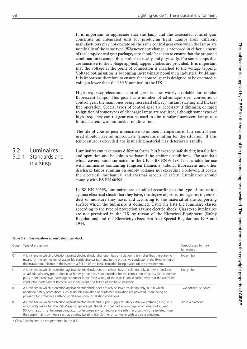
6868 Lighting Guide 1: The industrial environment Lighting Guide 1: The industrial environment
It is important to appreciate that the lamp and the associated control gear constitute an integrated unit for producing light. Lamps from different manufacturers may not operate on the same control gear even when the lamps are nominally of the same type. Whenever any change is proposed in either element of the lamp/control gear package, care should be taken to ensure that the proposed combination is compatible, both electrically and physically. For some lamps that are sensitive to the voltage applied, tapped chokes are provided. It is important that the voltage at the point of connection is matched to the voltage tapping. Voltage optimisation is becoming increasingly popular in industrial buildings. It is important therefore to ensure that control gear is designed to be operated at voltages lower than the 230 V nominal in the UK.
High-frequency electronic control gear is now widely available for tubular fluorescent lamps. This gear has a number of advantages over conventional control gear, the main ones being increased efficacy, instant starting and flicker-free operation. Special types of control gear are necessary if dimming or rapid re-ignition of some types of discharge lamps are required, although some types of high-frequency control gear can be used to dim tubular fluorescent lamps to a limited extent, without further modification.
The life of control gear is sensitive to ambient temperature. The control gear used should have an appropriate temperature rating for the situation. If this temperature is exceeded, the insulating material may deteriorate rapidly.
Luminaires can take many different forms, but have to be safe during installation and operation and be able to withstand the ambient conditions. The standard which covers most luminaires in the UK is BS EN 60598. It is suitable for use with luminaires containing tungsten filaments, tubular fluorescent and other discharge lamps running on supply voltages not exceeding 1 kilovolt. It covers the electrical, mechanical and thermal aspects of safety. Luminaires should comply with BS EN 60598.
In BS EN 60598, luminaires are classified according to the type of protection against electrical shock that they have, the degree of protection against ingress of dust or moisture they have, and according to the material of the supporting surface which the luminaire is designed. Table 5.2 lists the luminaire classes according to the type of protection against electric shock. Class zero luminaires are not permitted in the UK by reason of the Electrical Equipment (Safety Regulations) and the Electricity (Factories Act) Special Regulations 1908 and 1944.
5.2 Luminaires5.2.1 Standards and
markings
Table 5.2 Classifi cation against electrical shock
Class Type of protection Symbol used to mark luminaires
0* A luminaire in which protection against electric shock relies upon basic insulation; this implies that there are no means for the connection of accessible conductive parts, if any, to the protective conductor in the fi xed wiring of the installation, reliance in the event of a failure of the basic insulation being placed on the environment.
No symbol
I A luminaire in which protection against electric shock does not rely on basic insulation only, but which includes an additional safety precaution in such a way that means are provided for the connection of accessible conductive parts to the protective (earthing) conductor in the fi xed wiring of the installation in such a way that the accessible conductive parts cannot become live in the event of a failure of the basic insulation.
No symbol
II A luminaire in which protection against electric shock does not rely on basic insulation only, but in which additional safety precautions such as double insulation or reinforced insulation are provided, there being no provision for protective earthing or reliance upon installation conditions.
Two concentric boxes
III A luminaire in which protection against electric shock relies upon supply at safety extra low voltage (SELV) or in which voltages higher than SELV are not generated. The SELV is defi ned as a voltage which does not exceed 50 volts. a.c., r.m.s. between conductors or between any conductor and earth in a circuit which is isolated from the supply mains by means such as a safety isolating transformer or converter with separate windings.
‘III’ in a diamond
* Class 0 luminaires are not permitted in the U.K.
This publication is supplied by CIB
SE
for the sole use of the person making the dow
nload. The content remains the copyright property of C
IBS
E

Equipment 69Equipment 69
The degree of protection the luminaire provides against the ingress of dust and moisture is classified according to the IP system. This system describes a luminaire by two digits, for example, IP54. The first digit classifies the degree of protection the luminaire provides against the ingress of solid foreign bodies from fingers and tools, to fine dust. The second digit classifies the degree of protection the luminaire provides against the ingress of moisture. A third digit did exist to classify a luminaire’s impact resistance but this has now been superseded by the IK rating system which is described in BS EN 62262. Table 5.3 lists the classes of the two digits. Table 5.4 lists the IP numbers which correspond to some commonly used descriptions of luminaire types. Table 5.5 lists the symbols which may be used to mark the luminaires in addition to the IP number.
BS EN 60598 applies to most luminaires intended for use in neutral or hostile environments (including luminaires with type of protection N (non-sparking)). It does not apply to many of the luminaires intended for use in hazardous environments, i.e. environments in which there is a risk of fire or explosion. For such applications there are different requirements so different standards and certification procedures apply. Detailed guidance on this topic can be found in the SLL Lighting Handbook.
Table 5.3 The degrees of protection against the ingress of solid bodies (fi rst characteristic numeral) and moisture (second characteristic numeral) in the ingress protection (IP) system of luminaire classifi cation
First characteristic numeral
Degree of protection
Short description Brief details of objects which will be ‘excluded’ from the luminaire
0 Non-protected No special protection
1 Protected against solid objects greater than 50 mm
A large surface of the body, such as a hand (but no protection against deliberate access). Solid objects exceeding 50 mm in diameter.
2 Protected against solid objects greater than 12 mm
Fingers or similar objects not exceeding 80 mm in length. Solid objects exceeding 12 mm in diameter
3 Protected against solid objects greater than 2.5 mm
Tools, wires, etc., of diameter or thickness greater than 2.5 mm. Solid objects exceeding 2.5 mm in diameter.
4 Protected against solid objects greater than 1.0 mm
Wires or strips of thickness greater than 1.0 mm. Solid objects exceeding 1.0 mm in diameter
5 Dust-protected Ingress of dust is not totally prevented but dust does not enter in suffi cient quantity to interfere with satisfactory operation of the equipment
6 Dust-tight No ingress of dust
Second characteristic numeral
Degree of protection
Short description Details of the type of protection provided by the luminaire
0 Non-protected No special protection
1 Protected against dripping water Dripping water (vertically falling drops) shall have no harmful effect.
2 Protected against dripping water when tilted up to 15°
Vertically dripping water shall have no harmful effect when the luminaire is tilted at any angle up to 15° from its normal position
3 Protected against spraying water Water falling as a spray at an angle up to 60° from the vertical shall have no harmful effect
4 Protected against splashing water Water splashed against the enclosure from any direction shall have no harmful effect
5 Protected against water jets Water projected by a nozzle against the enclosure from any direction shall have no harmful effect
6 Protected against heavy seas Water from heavy seas or water projected in powerful jets shall not enter the luminaire in harmful quantities
7 Protected against the effects of immersion
Ingress of water in a harmful quantity shall not be possible when the luminaire is immersed in water under defi ned conditions of pressure and time
8 Protected against submersion The equipment is suitable for continuous submersion in water under conditions which shall be specifi ed by the manufacturer.
This publication is supplied by CIB
SE
for the sole use of the person making the dow
nload. The content remains the copyright property of C
IBS
E

7070 Lighting Guide 1: The industrial environment Lighting Guide 1: The industrial environment
Table 5.4 Ingress protection (IP) numbers corresponding to some commonly used descriptions of luminaire types and the symbols which may be used to mark a luminaire in addition to the IP number
Commonly used description of luminaire type IP Number* Symbol which may be used in addition to the IP classifi cation number
Ordinary ................................................................................. IP20** no symbolDrip-proof .............................................................................. IPX1 (one drop)Rain-proof .............................................................................. IPX3 (one drop in square)Splash-proof .......................................................................... IPX4 (one drop in triangle)Jet-proof ................................................................................ IPX5 (two triangles with one drop in each)Watertight (immersible) .......................................................... IPX7 (two drops)Pressure-watertight (submersible) ........................................... IPX8 (two drops followed by an indication of the maximum depth of
submersion in metres)Proof against 1mm diameter probe ........................................ IP4X no symbolDust-proof ............................................................................. IP5X (a mesh without frame)Dust-tight .............................................................................. IP6X (a mesh with frame)
* Where X is used in an IP number, it indicates a missing characteristic numeral. However, on any luminaire, both appropriate characteristic numerals should be marked.** Marking of IP 20 on ordinary luminaires is not required. In this context an ordinary luminaire is one without special protection against dirt or moisture.
Table 5.5 Information which should be marked on luminaires (from BS EN 60598)
1. Mark of origin. 2. Rated voltage(s) in volts. (Luminaires for tungsten fi lament lamps are only marked if the rated voltage is different from 250 volts). 3. Rated maximum ambient temperature if other than 25 °C (t
a…°C).
4. Symbol of class II or class III luminaire, where applicable. 5. Ingress Protection (IP) number, where applicable. 6. Maker’s model number or type reference. 7. Rated wattage of the lamp(s) in watts. (Where the lamp wattage alone is suffi cient, the number of lamps and the type shall also be given.
Luminaires for tungsten fi lament lamps should be marked with the maximum rated wattage and number of lamps). 8. Symbol of luminaires with built-in ballast or transformers suitable for direct mounting on normally fl ammable surfaces, if applicable. 9. Information concerning special lamps, if applicable.10. Symbol for luminaires using lamps of similar shape to ‘cool beam’ lamps where the use of a ‘cool beam’ lamp might impair safety, if
applicable.11. Terminations to be clearly marked to identify which termination should be connected to the live side of the supply, where necessary for safety
or to ensure satisfactory operation. Earthing terminators should be clearly indicated.12. Symbols for the minimum distance from lighted objects, for spotlights and the like, where applicable.
In addition to the above markings, all details which are necessary to ensure proper installation, used and maintenance should be given either on the luminaire or on a built-in ballast or in the manufacturer’s instructions provided with the luminaire.
5.2.2 Summary of luminaire characteristics
Table 5.6 summarises the properties of the luminaires which are most likely to be used in lighting for industry. The column headings indicate, from left to right, the common name of the luminaire type, the light source for which it is usually available (identified by the prefix letters (see Table 5.l)), the usual mounting position, the typical light distribution and some of the applications where the luminaires are commonly used. The table only gives an overview of the many types of luminaires available. For exact information on any specific luminaire the manufacturer should always be consulted.
Control systems are an inherent part of any lighting installation. They can take many forms, varying from a simple wall switch to being a part of a sophisticated microprocessor-controlled, building management system. Whatever the method used, the aim of a control system is always to ensure that the lighting system is only operating when it is required, and that when it is, it is operating in the required state. The aim of most control systems is to vary the light output of the installation, either by switching or by dimming the lamps.
In principle, all light sources can be switched but the light output that is immediately available when switched on, and the interval necessary between restarts, varies with lamp type (see Table 5.1). Generally, switching can be achieved by a number of different methods. The simplest is the manual switch.
5.3 Control systems
5.3.1 The function of control systems
5.3.2 Switching
This publication is supplied by CIB
SE
for the sole use of the person making the dow
nload. The content remains the copyright property of C
IBS
E

Equipment 71Equipment 71
Table 5.6 Summary of luminaire characteristics
Luminaire type Suitable lamp types Mounting positions
Typical luminous intensity distributions
Typical application
Cone GLS, compact MCF Pendant Widespread but downward Industrial premises
Bare batten MCF Surface or pendant
In all directions Industrial premises
Trough refl ector MCF Surface or pendant
Widespread but downward, some upward light if trough has slots
Industrial premises
Linear enclosed MCF Surface or pendant
Widespread Industrial premies where lamps have to be enclosed, e.g. for protection from damp, dust or corrosion
Linear prismatic/opal MCF Surface or pendant
Varies widely depending on the characteristics of the prismatic opal panel
Industrial premises where glare control is required
Recessed louvre MCF, MBF, (HPEN), MBI, (HPI), SON, (HPS)
Recessed Varies with refl ector used Industrial premises where close control of glare is required
Bare lamp refl ector MBFR (HPL-R)SON-R Surface or pendant
Widespread but downwards High bay industrial premises
Bare lamp refl ector with anti-glare skirt
MBFR (HPL-R)SON-R Surface or pendant
Widespread but downwards High bay industrial premises
High bay refl ector MBF, (HPL-N), MBI, SON, (HPS)
Surface or pendant
Concentrated downwards High bay industrial premises
Low bay MBF, (HPL-M), SON, (HPS)
Surface, pendant or recessed
Widespread but downward, depending on whether refl ectors, prismatics, diffusers or louvres are used in the luminaire
Industrial premises where low mounting heights are unavoidable
Bulkheads GLS, MBF, (HPL-N), SON, SOX, Compact MCF
Surface Widespread Industrial premises, exterior areas around buildings
Floodlighting projector GLS, TH, SON, SOX, MBF, MBI, (HPI), (HPLN)
Pole or surface Varies with the shape of the refl ector used
Industrial area fl oodlighting; security lighting
Street lighting lanterns SOX, SON, MBF, (HPL-N), MBI, (HPI)
Pole or surface Widespread but closely controlled within specifi c angles
Road lighting, security lighting area lighting
Post top lantern SOX, SON, MBF, (HPL-N), MBI, (HPI)
Pole In all directions Road lighting, exterior amenity lighting
Small tungsten halogen fl oodlight
TH Pole or surface Widespread but fl at Area fl oodlighting
Manufacturers should always be consulted for exact data
Remote switches which use an infrared transmitter and a receiver on the luminaire are also available. Both these forms of switching require human initiative. Alternative forms of switching operate without human intervention. Lamps can be switched by time switches or in response to the availability of daylight or the occupation of an area. Photocells are used to sense the level of daylight available, whilst sensors of noise level, movement and emitted or reflected radiation have all been used to detect people’s presence.
One particular aspect of switching which has limited its use in the past has been the difficulty of switching individual or small groups of luminaires without excessive investment in wiring. Recent developments in elec tronics have made it possible to send switching signals by low voltage wiring or by high frequency transmission pulses over the existing supply wiring. Further, logic circuitry now exists which allows individual luminaires to respond in one of several different ways. Such systems provide great flexibility in the way the lighting installation can be used.
Whenever the ability to steadily diminish the illuminance in a room is desirable, dimming is required. Tungsten filament lamps can be readily dimmed. Not all
5.3.3 Dimming
This publication is supplied by CIB
SE
for the sole use of the person making the dow
nload. The content remains the copyright property of C
IBS
E

7272 Lighting Guide 1: The industrial environment Lighting Guide 1: The industrial environment
discharge lamps can be dimmed and those that can, such as tubular fluorescent lamps, may need special control gear. Dimming lamps reduces the energy consumed by the lamp, but not necessarily in proportion to the light output, and usually changes its colour properties. Dimmers can be controlled manually or automatically in response to daylight availability. Many of the electronic developments mentioned in relation to switching can also be associated with dimming. Useful advice on the selection of lighting control systems is given in the BRE Digest 272: Lighting Controls and Daylight Use.
Maintenance of lighting systems keeps the performance of the system within the design limits, promotes safety, and, if considered at the design stage, can help to minimise the electrical load and capital costs. Mainten ance includes replacement of failed or deteriorated lamps and control gear, and the cleaning of luminaires and room surfaces at suitable intervals. Detailed advice on lighting maintenance can be found in CIE Publications 97-2005 and 154-2003.
There are two factors which need to be considered when determining the timing of lamp replacement; the change in light output and the probability of lamp failure. The relative weight given to these two factors depends on the lamp type. Tungsten halogen lamps, which have a filament, usually fail before the decline in light output becomes significant. Therefore the replacement time for these lamps is determined by the probability of lamp failure alone. All the other light sources conventionally used in industry show a significant reduction in light output before a large proportion fail. Therefore, for these lamps, both the decline in light output and the probability of lamp failure are important in determining the lamp replacement time. Frequently it is desirable to replace such lamps even though they are still operating electrically, simply because the light output has fallen to an uneconomic level.
For the majority of installations the most sensible procedure is to replace all the lamps at planned intervals. This procedure, which is known as group replacement, has visual, electrical and financial advantages over the alternative of replacing individual lamps as they fail. Visually, group replacement ensures that the installation maintains a uniform appearance. Electrically, group replacement reduces the risk of damage to the control gear caused by lamps nearing the end of their electrical life. Financially, by arranging that the lamp replacement is associated with luminaire cleaning, and doing it at a time when it will cause the minimum of disturbance to the activities, the cost of lamp replacement can be minimised. Group replace ment is an appropriate procedure for routine maintenance. However, in any large installation, a few lamps can be expected to fail prematurely. Failure of control gear and luminaire components may occur, unless these lamps are replaced promptly.
No matter whether lamps are replaced individually or in a group, a decision has to be made about the replacement light source. As light source development proceeds there is a temptation to replace one light source with another which is superficially similar but of higher luminous efficacy. If this course of action is attempted great care should be taken to establish that the replacement light source and the existing control gear are compatible; physically and electrically. Before replacing any discharge light source with another of a different type, or the same type but from a different manufacturer, advice on compatibility should be sought from the manufacturers.
The timing and nature of lamp replacement is usually a matter of economic and managerial judgement and may well be determined by factors other than those directly related to the lighting. The proposed lamp replacement procedure should be considered during the design of the installation.
If lamps are to be disposed of in any quantities, they must be dealt with in accordance with the WEEE Regulations.
5.4 Maintenance of lighting equipment
5.4.1 Introduction
5.4.2 Lamp replacement
5.4.2.1 Bulk disposal of lamps
This publication is supplied by CIB
SE
for the sole use of the person making the dow
nload. The content remains the copyright property of C
IBS
E

Equipment 73Equipment 73
Staff should be instructed to segregate lamp types and allocate them immediately where possible to their appropriate containers. If no containers are available then they must quarantine the lamps prior to collection by an authorised recycling organisation. Staff should be suitably protected in case of lamp breakage and wear suitable protective clothing, in particular eye protection and gloves to guard against broken glass.
All sodium lamps should be handled extremely carefully in a well ventilated area outdoors, in a dry atmosphere. As sodium reacts violently with water, precautions should also be taken against fire.
Although most modern lamps contain only minute amounts of mercury there are other chemicals present which could cause discomfort to the skin and eyes, and they should be treated with respect if broken accidentally. This is very much a Health and Safety issue which should be carried out and documented in accordance with current statutory requirements.
The rate at which dirt is deposited on and in a luminaire depends on the amount and composition of the dirt in the atmosphere, and on the type of luminaire. Over the same period and in the same location dustproof (IP5X) and dust tight (IP6X) luminaires and open reflectors with slots in the top will collect less dirt than louvred luminaires with closed tops, or luminaires with unsealed diffusers. This last type frequently acts as a dust trap.
For particularly dirty atmospheres or where access is difficult it is usually best to have either dustproof (IP5X) or dust tight (IP6X) luminaires, ventilated luminaires which are designed to use air currents to keep them clean, or lamps with internal reflectors. If cleaning is to be done in situ by water jets then luminaires suitably protected from moisture penetration must be used (IP5X). It is important to note that even the most protected luminaires, for example, dust tight (IP6X) luminaires, will collect dirt on their external surfaces. Therefore even these luminaires will need cleaning regularly (see Section 5.2.1 for a description of the IP system).
The appropriate cleaning interval for luminaires and the lamps they contain is again an economic and managerial question. The factors that need to be considered are the cost and convenience of cleaning at a particular time and the prevailing efficiency of the installation. As a general guide, luminaires should be cleaned at least once a year during an annual shutdown, but for some locations this will not be sufficient. It is usually advantageous to co-ordinate luminaire cleaning with lamp replacement if the latter is required.
The Factories Act 1961 stipulates that room surfaces in factories should be cleaned and redecorated regularly, but regular cleaning is important in all buildings if a dirty appearance is to be avoided. Regular cleaning is particularly important where light reflected from the room surfaces makes a major contribution to the lighting of the interior, e.g. where daylight from the side windows is used or where an indirect lighting installation is present.
The maintenance procedures for a lighting installation should be con sidered at the design stage. Three aspects are particularly important. The first is the maintenance factor to be used in the calculation of the number of lamps and luminaires needed to provide the required conditions.
Typical maintenance factors used for industrial lighting, assuming replacement of failed or broken lamps and annual cleaning of equipment can be found in the
5.4.3 Luminaire cleaning interval
5.4.4 Room surface cleaning interval
5.4.5 Design aspects
This publication is supplied by CIB
SE
for the sole use of the person making the dow
nload. The content remains the copyright property of C
IBS
E

7474 Lighting Guide 1: The industrial environment Lighting Guide 1: The industrial environment
SLL Lighting Handbook. Maintenance factors for exterior lighting for different degrees of ingress protection, air pollution and cleaning interval can be found in the SLL Lighting Handbook also.
The second aspect is the practical one of access and handling. Good maintenance will only occur if access to the lighting installation is safe and easy, and the lighting equipment is simple to handle. Figure 5.1 show two type of lighting columns designed for easy maintenance.
The third aspect is equipment selection. The dirtier the atmosphere where the installation is to operate, the more important it is to select equipment which is resistant to dirt deposition.
A wide range of different materials are used in luminaires. Table 5.7 summarises the most suitable cleaning methods for use with these different materials. In addition, ultrasonic cleaning techniques can be incorporated where appropriate.
Different lighting installations call for different levels of skill from the people doing the maintenance. For completely conventional installations only the most basic knowledge is necessary, but where luminaires with special properties, e.g. dust proof (IP5X), jet proof (IPX5), are used, considerable knowledge and care is required from the operator doing the cleaning and reassembly. Similarly, where complex control systems form a part of the installation, the maintenance operator will need to understand the operation of the system and the consequences of any changes made. For all maintenance work the operators should be aware of the basic electrical and mechanical safety aspects of the work.
Table 5.7 Suitable cleaning methods for lighting maintenance
Material Best cleaning compound
Alternative cleaners Remarks
Aluminium Soap and water Acidic or alkaline cleaners water may cause chalking of the oxide surfaces. Aluminium should be rinsed thoroughly after cleaning.
Glass Detergents and water Proprietary glaze cleaners Polishing pastes and fl uids are not recommended as these may leave a fi lm on the glass surface which affects its characteristics in relation to moisture and dirt adhesion. Paraffi n must not be used.
Plastics (including GRP) Non-ionic detergents and water
Ordinary detergents and water
Dust accumulates due to a static charge developing on the plastic. It should not, therefore, be wiped, but allowed to drip-dry after cleaning. De-staticisers are commercially available either as a polish, spray or solution in the rinse bath.
Vitreous enamel Detergents and water Proprietary glaze cleaners See remarks appertaining to glass.
Stoved enamel and paints Detergents and water Abrasive cleaners should not be used as they will injure the fi nish.
6 Lighting design
6.1 Introduction
6.2 Objectives
Figure 5.1 Two types of hinged columns for maintenance at ground level
5.4.6 Practical aspects
C of hingeL
Lowered withhydrauliccounter balance
Door
Cable entry
Lighting design is a complex process and no hard and fast rules can be devised which will suit all design problems or every designer. Nevertheless, the following design approach represents reasonable practice and will give guidance to less experienced designers.
The first stage in planning any lighting installation is to establish the lighting design objectives. Care and time expended on this is well invested, because the objectives guide the decisions in all the other stages of the design process. The lighting objectives can be considered in three parts.
This publication is supplied by CIB
SE
for the sole use of the person making the dow
nload. The content remains the copyright property of C
IBS
E

Lighting design 75Lighting design 75
The lighting must be safe and must allow the occupants to work and move about safely. There are not only primary objectives but also statutory obligations. It is, therefore, necessary to identify any hazards present and to consider the most appropriate form of emergency lighting.
The type of work that takes place in the interior will define the nature and variety of the visual tasks. An analysis of the visual tasks (there is rarely just one) in terms of size, contrast, duration, need for colour discrimination and so on, is essential to establish the quantity and quality of the lighting required to achieve satisfactory visual conditions. In addition to est ablishing the nature of the tasks done in an interior, it is also necessary to identify the positions where the tasks occur, the planes on which the tasks lie, and the extent of any obstruction. This information is essential if lighting matched to the tasks is to be provided.
The lighting of a space will affect its character and the character of objects within it. It is, therefore, necessary to establish what mood or atmosphere is to be created. This is not a luxury to be reserved only for prestige offices, places of entertainment, and the like, but should be considered in all designs.
When establishing the objectives, it is important to differentiate between those which are essential and those which are desirable. It is also important at this stage to establish both the design objectives and the design constraints. There are many constraints which may affect the design objectives, such as allowed budget, energy consumption, environmental considerations including compliance with the latest edition of Part L of the Building Regulations, physical problems of access, and so on. Some projects have other constraints such as BREEAM or LEED requirements. These constraints must be recognised at the objectives stage of the design.
Once the lighting objectives have been defined, they must be quantified wherever possible. However, not all design objectives can be quantified. For example, the need to make an environment appear efficient cannot be quantified. Furthermore, although many objectives can be expressed in physical terms, suitable design techniques may not exist or may be too cumbersome. For example, obstruction losses are difficult to calculate and predict accurately. This does not mean that the objectives represented by these terms should be ignored, but that experience and judgement may have to replace calculation.
When the design specification has been established the purpose of the remaining stages of design is to translate these requirements into the best possible solutions, with the intention of meeting the original objectives.
Indeed, if it proves difficult to plan an installation it may be necessary to reassess the original objectives.
Experience and judgement will usually dominate the planning process. Nevertheless, the planning stages can be divided into general planning and detailed planning (see Section 6.5). Calculation methods can be found in detail in the SLL Code for Lighting.
The first stage in the general planning of a lighting installation is to consider the interior to be lit, its proportions, its contents, and most importantly the daylight available.
A comprehensive assessment of the role of windows and rooflights in buildings is given in the SLL Lighting Guide 10: Daylighting and Window Design. In industry, the most common means of admitting daylight is by rooflights. Therefore this guide will restrict the consideration of daylight to the role of
6.3 Specifi cation
6.4 General planning
6.4.1 Daylight
This publication is supplied by CIB
SE
for the sole use of the person making the dow
nload. The content remains the copyright property of C
IBS
E

7676 Lighting Guide 1: The industrial environment Lighting Guide 1: The industrial environment
rooflights. Specifically, the question that needs to be considered is how the electric lighting should relate to the natural lighting. Electric lighting is usually planned as if daylight did not exist. However natural lighting may well suggest the form and especially the control system of the electric lighting. For this reason every lighting designer needs some knowledge of daylight prediction.
In temperate climates, the extent to which daylight is available at a position in an interior is conventionally expressed as a ‘daylight factor’. This is the illuminance at a point on a plane in an interior due to light received directly or indirectly from a sky of known or assumed luminance distribution expressed as a percentage of the illuminance on a horizontal plane due to an unobstructed hemisphere of the same sky. The sky usually assumed is the overcast sky, as specified by the CIE. The average daylight factor (%) on a horizontal reference plane in an empty interior is given approximately by the following expression:
average daylight factor =
T W h
A (1 − R2)
where T = transmittance of glazing material, expressed as a decimal
W = net area of glazing (m2)
h = angle (degrees) in vertical plane, subtended by sky visible from the centre of a rooflight (see Figure 6.1)
A = total area of indoor surfaces: ceiling + floor + walls, including windows or rooflights (m2)
R = area weighted average reflectance of all indoor surfaces, including the rooflights
When the average daylight factor is 5% or greater, an interior will generally look well day-lit. When the average daylight factor is less than 2%, the interior will not be perceived as well day-lit and electric lighting may be in constant use throughout the day.
When the average daylight factor exceeds 5% in a building that is used mainly during the day, local manual or automatic controls should be provided to turn off general lighting, where daylight can provide the required quantity and quality of light.
When the average daylight factor is between 2 and 5%, the electric lighting should be planned to take full advantage of available daylight. Localised or local lighting may be particularly advantageous, using daylight to provide the general surround lighting.
Average daylight factor will often give the designer sufficient information on which to base decisions on the relationship between natural and electric lighting.
Lighting systems which provide an approximately uniform illuminance over the whole ‘working’ plane are called ‘general-lighting systems’. The luminaires are normally arranged in a regular layout. General lighting is simple to plan using modern computer programs and requires no coordination with task locations. The lumen method can also be used for quick estimates of luminaire quantities in general lighting schemes. The greatest advantage of such systems is that they permit complete flexibility of task location.
The major disadvantage of using just general lighting to achieve high task lighting levels is that energy may be wasted when illuminating the whole area to
Figure 6.1 Maximum h on a shed roof
6.4.2 Choice of electric lighting systems
6.4.2.1 General lighting
h
This publication is supplied by CIB
SE
for the sole use of the person making the dow
nload. The content remains the copyright property of C
IBS
E

Lighting design 77Lighting design 77
the level needed for the most critical tasks. Energy will be saved by using the general lighting to provide the lower ambient level for circulation and other non-critical tasks, and providing the higher illuminance over only the task or task areas by adding local or localised lighting where needed.
Localised lighting systems employ an arrangement of luminaires designed to provide the required maintained illuminances over specific work areas together with a lower illuminance for the other areas. For guidance as to the relative illuminance necessary in both the ‘immediate surrounding area’ and the ‘background area’ reference should be made to Table 2.1.
Considerable care must be taken to coordinate the lighting layout to task positions and orientation. The system can be inflexible and correct information is essential at the design stage. Changes in the work layout can seriously impair a localised system, although easily relocatable or switchable systems can overcome these problems.
Localised systems normally consume less energy than general-lighting systems unless a high proportion of the area is occupied by work stations. This should be confirmed by specific calculations. Localised systems may require more maintenance than general lighting systems.
Local lighting provides illumination only over the small area occupied by the task and its immediate surroundings. A general-lighting system must be installed to provide sufficient ambient illumination for circulation and non critical tasks. This is then supplemented by the local-lighting system to achieve the necessary illuminance on tasks. The ‘immediate surrounding area’ illuminance should not be less than one-third of the task illuminance.
Local lighting can be a very efficient method for providing adequate task illumination, particularly where high illuminances are necessary and/or flexible directional lighting is required. Local lighting is frequently provided by luminaires mounted on the work station.
Fixed local lighting must be positioned to minimise shadows, veiling reflections and glare. Although local luminaires allow efficient utilisation of emitted light, the luminaires themselves may be inefficient and can be expensive. Most local lighting systems are accessible and often adjustable.
This increases wear and tear and hence maintenance costs but provides some individual control.
Both local and localised lighting offer scope for switch control of individual luminaires which can be off when not required, but care must be taken to ensure that sufficient ambient illumination is provided.
The choice of lamp will affect the range of luminaires available, and vice-versa. Therefore, one cannot be considered without reference to the other. Tables 6.1 and 6.2 list some typical mounting heights for some common lamp/luminaire combinations used for interior lighting and exterior area lighting respectively.
The designer should compile a list of suitable lamps, by rejecting those which do not satisfy the design objectives. The availability of suitable luminaires can then be checked and the economics of each assessed. General guidance can be obtained from Section 5.2.
The run-up time of most discharge lamps (excluding fluorescent lamps) is unsatisfactory for applications requiring rapid provision of illumination or switching control unless auxiliary tungsten halogen lamps are provided.
6.4.2.2 Localised lighting
6.4.2.3 Local or task lighting
6.4.3 Choice of lamps and luminaires
6.4.3.1 Choice of lamp
This publication is supplied by CIB
SE
for the sole use of the person making the dow
nload. The content remains the copyright property of C
IBS
E

7878 Lighting Guide 1: The industrial environment Lighting Guide 1: The industrial environment
Table 6.1 Typical mounting height ranges for some common lamp/luminaire combinations used in interior lighting
Lamp and luminaire Typical mountingHeights in metres
Notes
min. max.
Fluorescent luminaire with trough refl ector, any wattage/length
2.5 8 Usually diffi cult to maintain at heights over 5 m
Fluorescent luminaire with controller, e.g. opal, prismatic or louvre; any wattage/length
2 4 Upper limit depends on manufacturer’s photometric data and lumen output of lamps
Discharge (SON, MBI(HPI)) luminaire with opal, prismatic or louvre controller, Up to 250 W SON or Up to 400 W MH(HPI)
2.5 5 Upper limit depends on manufacturer’s photometric data and lumen output of lamp
High bay type luminaire dispersive or concentrating Up to 150 W SON or 250 W MH 4 8 Up to 250 W SON or 400 W MH 5 8 Up to 400 W SON or 1000 W MH 7 12 Up to 1000 W SON or 2000 W MH 12 no limit
Low bay type luminaire, bare lamp or controller Up to 150 W SON or 250 W MH 3 5 Up to 250 W SON or 400 W MH 4 5 Up to 400 W SON or 1000 W MH 5 7
Note Mercury (MBFU) lamps have been omitted from this table because they are now considered ineffi cient and require large amounts of maintenance.
Industrial luminaires are becoming available with LEDs for the light source. Wattages vary, and advice must be sought from the manufacturers regarding photometric performance and suitability for a particular purpose.
Table 6.2 Typical minimum mounting height ranges for fl oodlights used in area lighting schemes
Lamp Nominal rating (W)
Initial lumens
Typical minimum mounting height (m)
Compact fl uorescent (CFL) 16–57 <4800 370 5200 4
2x36–2x80 >5200 5
Metal Halide (HQI)(HPI)(CDM) 35 3300 3 including ceramic 70 6500 4
150 11 000 5250 20 000 6400 35 000 7
1000 80 000 10
High pressure sodium (SON) 50–70 6500 4100 10 000 5150 17 200 6250 33 000 7400 55 000 8
1000 130 000 12
NB 1. Mercury (MBFU) lamps have been omitted from this table because they are now considered ineffi cient and require large amounts of maintenance.2. These recommended minimum mounting heights do not apply to schemes using street lighting lanterns3. Floodlight luminaires are becoming available with LEDs for the light source. Wattages vary, and advice must be sought from the manufacturers regarding photometric performance and suitability for a particular purpose.
This publication is supplied by CIB
SE
for the sole use of the person making the dow
nload. The content remains the copyright property of C
IBS
E

Lighting design 79Lighting design 79
Lamps must have colour rendering properties suited to their intended use. Good colour rendering may be required in order to achieve better discrimination between colours where that is part of the visual task. The life and lumen maintenance characteristics of the lamps must be considered to arrive at a practicable and economic maintenance schedule.
Standardisation of lamp types and sizes within a particular site or company can simplify maintenance and stocking.
In the choice of luminaire, the designer can exercise a combination of professional judgement, personal preference and economic analysis. Luminaires may have to withstand a variety of physical conditions, such as vibration, moisture, dust, ambient temperature, vandalism and so on. In addition, the onus is on the designer to specify safe equipment. Safety can be guaranteed by using equipment with the British Standard safety mark or obtaining written assurances from the manufacturer. It is important to ensure that equipment is selected which can withstand and operate safely in the environmental conditions that will be encountered. The ingress protection rating gives guidance regarding the ability of the luminaire to withstand the ingress of solid foreign bodies and moisture. The designer must make sure that the manufacturer’s claims apply throughout the intended life of the luminaire. This is particularly true of a claimed IP rating, which, without further qualification, applies to a new luminaire. However, when a luminaire has the British Standard safety mark or ENEC Mark, the IP rating is applied to an already arduously tested luminaire.
Not only must the luminaire withstand the ambient conditions, it may have to operate in a hazardous area, such as a refinery, mine or similar environment. In this event, special equipment is required to satisfy the safety regulations. Such equipment is beyond the scope of this guide. This subject is covered to some extent in the SLL Lighting Handbook.
The light distribution of the luminaire should be carefully considered as it influences the distribution of illuminance and the directional effects that will be achieved.
Luminaire reliability and life will have a direct impact on the economics of the scheme, and must be realistically considered. The ease with which luminaires can be installed and maintained will also affect the overall economics and convenience of the scheme. Luminaires with good maintenance characteristics and which can be easily maintained will not only save on maintenance costs, but will also be more efficient throughout their life. Luminaires which can be unplugged and detached, or which have removable gear, can simplify maintenance by allowing remote servicing.
A good lighting system must not only be well designed, but must also be managed and operated effectively and efficiently. System management must: (a) control the use of the system to ensure efficiency, and (b) maintain the system in good order.
Methods of control fall into three broad categories: (a) manual control (managerial), (b) automatic control (non-intelligent), and (c) processor control (intelligent).
Manual methods rely upon individuals and appointed members of staff controlling the lighting system. These methods tend to be inexpensive in capital costs but may be less effective than automatic methods. To be effective the lighting system must be well planned to permit flexible switching of individual luminaires or banks of luminaires. The switch panels must be sensibly located and clearly marked (a mimic diagram can be very helpful). An education programme to
6.4.3.2 Choice of luminaire
6.4.4 System management
6.4.4.1 Choice of controls
6.4.4.2 Manual controls
This publication is supplied by CIB
SE
for the sole use of the person making the dow
nload. The content remains the copyright property of C
IBS
E

8080 Lighting Guide 1: The industrial environment Lighting Guide 1: The industrial environment
ensure staff awareness is essential and this can be reinforced with posters, and with labels on or adjacent to the switch panels.
One of the main snags with manual methods is that, whilst occupants may be aware that natural lighting is insufficient and will turn on lights, it is rare for them to respond to sufficient daylight by turning lights off. Automatic control in the form of an imposed switch-off (particularly at meal breaks) can be effective, since, if natural lighting is adequate, the luminaires may not be turned back on. A considerable amount of energy is often wasted after working hours when the lighting is left on to no useful purpose. The provision of automatic cleaners’ circuits controlling only some of the lighting to provide reduced illuminances can save money.
Automatic control systems, such as time switches, presence/absence detectors or photocells, can be inexpensive and can switch (or dim) banks of lights.
Photocells, or daylight control, can monitor the level of daylight and turn off or dim lamps when there is sufficient daylight. Whether or not this is economic will depend upon the daylight factor and the proportion of the working year for which the required illuminance is exceeded, as well as obstructions affecting the working task area. This type of control is best suited to factories with ‘northlight’ roof windows, rather than areas lit from the side by traditional windows.
Time switches are normally used for exterior lighting to prevent lights being on during daylight hours. However, they can be used internally in areas such as displays or showrooms, which only require lighting at certain times of the day. They should have an override fitted in case they need to be operated outside normal hours.
Presence and absence detectors provide a convenient method of ensuring that lighting is not being used when there is no-one around. Presence detectors can be used to detect the presence of occupants and to switch on the lights accordingly. These are most useful in WCs, corridors, storerooms and some warehouses. Absence detectors require a manual switch on and then switch off after a preset time if no occupants are detected, and are most suitable for rooms or areas which contain reasonable amounts of natural daylight, but only infrequently occupied, as they are only switched on if the occupier has insufficient daylight. Both these types can rely upon acoustic, infrared, microwave, or other methods of detection. A time-lag must normally be built into the system to prevent premature switch-offs.
Automatic systems must normally have some degree of manual override (on and off) to cater for unexpected circumstances. Systems which automa tically cancel lighting but must be manually reset can offer greater savings than those which switch on again automatically. Occupants can be relied upon to turn on lighting if they need it. Computer-based or microprocessor-based control systems are becoming increasingly popular, more reliable and less expensive. These rely upon dedicated computers or processors to control some or all of the building services, e.g. lifts, fire alarms, lighting, air-conditioning, etc. The most important advantages of such an approach are that complex decisions can be taken from moment to moment based upon the precise state of the building’s operation, and that the system is controlled by software. This last feature means that the control programs can be refined and tailored to suit the building and can be easily amended to suit changed circumstances.
With any control system, considerable care must be taken to ensure that acceptable lighting conditions are always provided for the occupants. Safety must always be of paramount importance.
6.4.4.3 Photocells and daylight control
6.4.4.4 Time switches
6.4.4.5 Presence and absence controls
6.4.4.6 Automatic controls
This publication is supplied by CIB
SE
for the sole use of the person making the dow
nload. The content remains the copyright property of C
IBS
E

Lighting design 81Lighting design 81
Control systems which are obtrusive or disruptive are counter-productive and may even be sabotaged by the staff. For this reason, dimmer systems are often preferred.
Further details on the choice of a lighting control system can be found in BRE Digest 272: Lighting Controls and Daylight Use.
Lighting systems must be serviced regularly and this must be allowed for at the design stage. Faulty or failed lamps should be replaced and unsafe or faulty equipment should be rectified. In addition, depreciation in illumination, caused by dirt on lamps, luminaires and room surfaces should be controlled by regular cleaning to maintain the required illuminance.
It is not always enough to replace lamps upon failure. The light output of lamps decreases after hours of operation. For most lamp types, a point will usually be reached where it is financially better to replace the lamps than to continue to waste power. Furthermore, labour charges for the replacement of individual lamps can be high, so it is often less expensive in the end to clean and service a complete installation when convenient, than to indulge in intermittent cleaning and re-lamping. Access to luminaires is important for maintenance and mounting over continuous process plant should be avoided. Raising and lowering units should be considered for luminaires at high-mounting heights, or mounted near to walk gantries where possible.
When the overall design has been resolved in general terms, detailed calculations are required to determine such things as the number of luminaires, the Glare Index, the final cost and so on.
The calculations which may have to be carried out during the design process can be found in the SLL Lighting Handbook.
Most illuminance calculations are carried out at present using one of the many computer programs available. Most of these are free of charge and enable calculations to be done quickly and easily. Some programs will also show 3D structures of complex rooms or areas and carry out realisation plots for visual evaluation. Some also create CAD drawings of the resultant design, showing luminaires, objects and room parameters ready for presentation to the client.
However, there are occasions when the lighting designer needs to calculate on site an approximate number of luminaires required for a project. This he can do easily with a calculator using the lumen method.
The average illuminance Es over a reference surface S can be calculated from the ‘lumen method’ formula:
EF n N
Ass
s
=MF UF
where F = the lamp luminous flux (lighting design lumens)
n = the number of lamps per luminaire
N = the number of luminaires
MF = the maintenance factor
UFs = the utilisation factor for the reference surface S
As = the area of the reference surface S (m2)
6.4.4.7 Maintenance
6.5 Detailed planning
6.5.1 Introduction
6.5.2 Average illuminance for interior lighting
This publication is supplied by CIB
SE
for the sole use of the person making the dow
nload. The content remains the copyright property of C
IBS
E

8282 Lighting Guide 1: The industrial environment Lighting Guide 1: The industrial environment
The formula can be re-arranged to permit the calculation of the number of luminaires required to achieve the chosen illuminance.
Utilisation factors can be obtained from luminaire manufacturers. The method for calculating utilisation factors for these surfaces is given in CIBSE Technical Memorandum 5: The Calculation and Use of Utilisation Factors.
To use utilisation factor tables it is necessary to know the room index and the room reflectances. For details regarding both utilisation factors and room indices reference should be made to the SLL Lighting Handbook.
Again, most area lighting calculations are carried out using one of many computer programs readily available. However, once more if a lighting designer needs to estimate an approximate number of luminaires required whilst on site, there is an external version of the lumen method available.
The average illuminance which will be achieved on a horizontal surface using area lighting techniques can be calculated approximately from the following formula:
EA
N s
s
=w BF WLF MF
where Es = average illuminance on the horizontal surface (S) (lux)
w = lamp luminous flux (initial)
N = number of lamps
BF = beam factor of luminaire
WLF = waste light factor
MF = maintenance factor
As = area of the horizontal surface, S (m2)
The beam factor of the luminaire and the light output of the lamp will be supplied by the manufacturer. The maintenance factor will depend on the location of the installation and the frequency of cleaning. As a first approximation, a combined beam factor, waste light factor and maintenance factor of 0.25 will often be satisfactory. For accurate estimation, illuminance should be calculated using a computerised design.
The design process for factory roadway lighting consists of seven parts:
(a) Gathering of preliminary data. This can include some or of all the items from the following list: roadway and footpath width; mounting height; lamp type; lantern arrangement; column location; bracket type; width from lantern to rear of footpath; cleaning interval; pollution category; photometric requirements of road; average illuminance; minimum point illuminance; road surface luminance; choice of lantern from manufacturers’ data; lamp flux; Ingress Protection code of lamp housing; downward light output ratio luminaire for the lantern; flux in lower hemisphere of the lighting; check whether lower hemisphere lumens exceeds 3500; glare control data of lighting; check the glare control requirements are met; check scale of isolux diagrams.
(b) Determination of a design spacing to provide a given minimum illuminance.
(c) Calculation of a design spacing to provide a given average illuminance.
6.5.4 Designing factory roadway lighting
6.5.3 Average illuminance for exterior areas
This publication is supplied by CIB
SE
for the sole use of the person making the dow
nload. The content remains the copyright property of C
IBS
E

Lighting design 83Lighting design 83
(d) Calculation of a design spacing to provide a given average road luminance.
(e) Determination of the design spacing which provides compliance with all the photometric requirements.
(f) Plotting of lantern positions taking into account the individual features of the road.
(g) Determination of column positions, taking into account the individual features of the site.
The gathering of preliminary data can be undertaken either on-site by measurement, from a detailed CAD drawing, or from a specification written by an architect, consulting engineer, or specialist lighting consultant. Sometimes the data is obtained from a mixture of all three sources.
This type of lighting design is nowadays, almost without exception, carried out using computerised design software. The speed and accuracy shown by these programs make it unviable in a commercial world to use hand calculations. However, there are methods of calculation by hand which are too lengthy for discussion in this guide. They can be found in the SLL Lighting Handbook.
When local or localised lighting systems are employed, or when irregular layouts of luminaires are used, or luminaires with unconventional light distributions are selected, or where there is considerable obstruction, calculations of average illuminance can be inadequate or meaningless. In such circumstances it is necessary to calculate the illuminance at all points of interest.
Where a computer is available with suitable programs, illuminance values at a particular point can be easily calculated. Virtual calculation surfaces can be placed anywhere in the room, horizontally or vertically, at an angle, and indeed at any height. In addition, 3D realisation is readily available and an immense option of results also, covering such topics as unified glare rating (UGR), surface luminance values, and mean cylindrical illuminance to name but a few.
The ease with which computers can be used often results in abuse. The quality of the results is only as good as the calculation approach used and the data on which the calculation is performed, though a computer printout can give the illusion of precision. Before using a computer program the designer should take care that the assumptions contained within the program are understood and should ensure that the data used is appropriate to the equipment and the situation of interest.
Figure 6.2 Dimensions for roadway lighting
6.5.5 Illuminance at a point
Carriageway
KerbKerb
Verge
Lantern
Footway
Back offootway
HMountingheight
Back offootway
Footway
Total roadway width
W2
W1
This publication is supplied by CIB
SE
for the sole use of the person making the dow
nload. The content remains the copyright property of C
IBS
E

8484 Lighting Guide 1: The industrial environment Lighting Guide 1: The industrial environment
The method of evaluating glare is the proper use of the UGR system. It is an empirical system whereby calculated values can be assessed against limiting values for certain tasks and room or area usage.
The calculation for glare is an involved and lengthy process, and one that should not be taken lightly. Modern computers are very versatile and will not only calculate accurate UGR values, but also allow the user to insert observers at specific points within the room.
For those persons who want to calculate the UGR from scratch, the information on how to do it can be found in the SLL Lighting Handbook.
The design aspects of emergency lighting are discussed in detail in SLL Lighting Guide 12: Emergency Lighting Design Guide, the basic points are also laid out in Section 3.19. In summary, there are two main supply systems, generators and batteries. Generators must provide the required illuminance within seconds, the actual times being at the discretion of the enforcing authority. Therefore, they must either be running continuously or automatically start within the maximum time allowed. If this cannot be achieved then auxiliary battery systems must be used.
Generators require considerable capital investment and are difficult to justify except for standby systems on large sites.
Battery systems can be of two types: central systems, where the batteries are in banks at one or more locations; and self-contained systems, where each individual luminaire has its own battery. Central systems have battery rooms or cubicles in which the charger, batteries and switching devices are located. Battery cubicles can be designed to simplify system maintenance. How ever, the system must be well designed if it is not to be rendered inoperative if damaged by fire.
Self-contained luminaires are self-powered and operate independently in an emergency. Thus, although an individual luminaire may be destroyed in a fire, the other luminaires will be unaffected. The fact that each luminaire is an independent unit means that maintenance must be thorough. Batteries, lamps and other components must be disposed of in accordance with WEEE Regulations and current Government guidelines. For most applications battery systems must operate for a period of 1 to 3 hours. Most designers base their designs on the 3-hour standard because clients are reluctant to guarantee in writing that occupants will not re-enter the building for 24 hours after the alarm was raised, a requirement of the 1-hour system. Self-contained luminaires can have three modes of operation:
(a) Maintained: in this the same lamp or lamps are used, powered normally by the mains supply. Under emergency conditions it uses its own battery supply.
(b) Non-maintained: in this the lamp is off when mains power is available to charge the batteries. Upon supply failure the lamp is energised from the battery pack.
(c) Sustained: this is a hybrid of the previous two. A lamp is provided which operates from the mains supply under normal conditions. Under emergency conditions a second lamp, powered from the battery pack, takes over. Sustained luminaires are often used for exit signs.
Systems of self-contained luminaires are the easiest and most flexible to install but their effective life is likely to be less than that of central battery systems.
6.5.7 Emergency lighting
6.5.7.1 Equipment options
6.5.6 Glare index
This publication is supplied by CIB
SE
for the sole use of the person making the dow
nload. The content remains the copyright property of C
IBS
E

Lighting design 85Lighting design 85
This is mainly due to the rechargeable batteries having a useful life of generally less than 7 years. Also, maintenance and testing must be thorough if operation in the event of emergency is to be guaranteed.
In order to ensure that the minimum illuminances are within the prescribed limits along the escape route, the calculation of illuminance is required. Methods and formulae for doing this are given in SLL Lighting Guide 12: Emergency Lighting Design Guide. It is important to base the calculations upon realistic photometric data for the luminaire and lamps. It is essential that the calculations portray the worst set of conditions that are likely to be encountered; the luminaires may be at the end of their cleaning and maintenance cycle; the lamps may be at the end of their useful life; the batteries may be at the end of their discharge period; the ambient temperature may be excessive; and so on. These are just examples, and the actual worst condition must be determined. It must be mentioned also that in many factories the exit doors lead to back lanes or alleys, where unofficial debris or rubbish can accumulate. Therefore, emergency lighting must be provided in these alleys through to a ‘place of safety’.
Many manufacturers provide design information to help in planning emergency lighting. It is important to use this data correctly and with the appropriate value of ‘emergency lighting design lumens’ for the lamp.
Emergency lighting calculations can be carried out within computer design programs. However, it must be remembered by the designer that the accuracy of the results depend on the accuracy of the information given. A photometric file of a single-lamp luminaire will yield accurate results when the lumen output of the lamp is adjusted by an ‘emergency lighting ballast lumen factor’. The same cannot be said of a twin lamp luminaire, as the photometric distribution changes considerably when only one lamp is lit during emergency operation. In this instance a photometric file appropriate to the lone lamp should be sought. The designer should also be aware that emergency lighting ballast lumen factors are only accurate for a particular ballast from a particular manufacturer. These factors vary considerably between 4% and 30% and advice should therefore be sought regularly from the luminaire manufacturer.
6.5.7.2 Calculating the illuminance along the escape route
This publication is supplied by CIB
SE
for the sole use of the person making the dow
nload. The content remains the copyright property of C
IBS
E

8686 Lighting Guide 1: The industrial environment Lighting Guide 1: The industrial environment
Light sources, both natural and electric, have two colour properties related to the spectral composition of their emission. One is the apparent colour of the light that the source emits and the other is the effect that the light has on the colours of surfaces. The latter effect is called colour rendering.
The colour of the light emitted by a ‘near white’ source can be indicated by its correlated colour temperature (CCT). Each lamp type has a specific correlated colour temperature but for practical use, the correlated colour temperatures have been grouped into three classes by the Commission International de l’Eclairage (CIE) (see Table A1.1).
Table A1.1 Correlated colour temperature classes and colour rendering groups used in this Guide
Correlated colour temperature (CCT) CCT class
CCT < 3300 K Warm3300 K < CCT < 5300 K Intermediate*
5300 K < CCT Cold
1A Ra > 90 Wherever accurate colour matching is required, e.g. colour
printing inspection.
1B 80 < Ra < 90 Wherever accurate colour judgements are necessary and/or good
colour rendering is required for reasons of appearance, e.g. shops and other commercial premises.
2 60 < Ra < 80 Wherever moderate colour rendering is required.
3 40 < Ra < 60 Wherever colour rendering is of little signifi cance but marked
distortion of colour is unaccepable.
4 20 < Ra < 40 Wherever colour rendering is of no importance at all and marked
distortion of colour is acceptable.
* This class covers a large range of correlated colour temperatures. Experience in the U.K. suggests that light sources with correlated colour temperatures approaching the 5300 K end of the range will usually be considered to have a ‘cool’ colour appearance.
A1.2 Colour rendering
Appendix 1: Light source colour
A1.1 Apparent colour of the emitted light
The choice of an appropriate apparent colour of light source for a room is largely determined by the function of the room. This may involve such psychological aspects of colour as the impression given of warmth, relaxation, clarity, etc., and more mundane considerations such as the need to have a colour appearance compatible with daylight and yet to provide a ‘white’ colour at night. The only general rules to help with the selection of apparent colour are (a) for rooms lit to an illuminance of 300 lux or less, a warm or intermediate colour is preferred; cold apparent colour lamps tending to give rooms a gloomy appearance at such illuminances and (b) different apparent colour lamps should not be used haphazardly in the same room.
The ability of a light source to render colours of surfaces accurately can be conveniently quantified by the CIE general colour rendering index. This index is based on the accuracy with which a set of test colours are reproduced by the lamp of interest relative to how they are reproduced by an appropriate standard light source, perfect agreement being given a value of 100. The CIE general colour rendering index has some limitations but it is the most widely accepted measure of the colour rendering properties of light sources. Table A1.1 shows the groups of the CIE general colour rendering index used by the CIE and in this Guide.
Where work involving accurate colour judgement is to be done, electric light sources with high CIE general colour rendering indices (i.e. from Groups 1A or 1B) are necessary. Where exact colour matching is to be done, lamps of colour rendering group 1A should be used and the recommendations of BS EN 950 should be followed as appropriate. The surfaces of surrounding areas where accurate colour judgements are being made should be of weak chroma (not greater
This publication is supplied by CIB
SE
for the sole use of the person making the dow
nload. The content remains the copyright property of C
IBS
E

Appendix 1 Light source colour 87Appendix 1 Light source colour 87
than 1) and medium reflectance (not less than 0.4). An illuminance of at least 500 lux should be provided on the task.
Where the main consideration is the appearance of the space and objects within it, light sources with a high CIE general colour rendering index may be desirable. In general, light sources with good colour rendering properties (Groups 1A and 1B) make surfaces of objects appear more colourful than light sources with moderate or poor colour-rendering properties (Groups 2, 3 and 4). In addition, light sources with poor colour-rendering properties may distort some colours to a marked extent. Thus, where a colourful appearance is desirable, lamps with good colour-rendering properties are appropriate. However, the exact level of colour rendering desirable in any particular circumstance remains a matter of individual judgement. Ultimately the CIE general colour rendering index is no substitute for actually seeing the effect of different light sources when it comes to assessing their contribution to the appearance of an interior.
This publication is supplied by CIB
SE
for the sole use of the person making the dow
nload. The content remains the copyright property of C
IBS
E

8888 Lighting Guide 1: The industrial environment Lighting Guide 1: The industrial environment
Field measurements of illuminance are usually undertaken for one of three reasons: (a) to establish whether a new installation has achieved the design specification; (b) to establish whether an installation meets a desired criterion; (c) as part of a process for identifying the causes of complaints about the lighting, i.e. trouble-shooting.
The same instrumentation is used for all three purposes although the nature of the measurements made will vary with the circumstances.
Illuminance meters usually consist of a selenium or silicon photovoltaic cell connected directly or indirectly by an amplifier to a display which can be analogue or digital. The quality of an illuminance meter is determined by four factors: (a) its spectral response; (b) its response to light incident on the photocell at different angles; (c) its linearity of response; and (d) its sensitivity to temperature.
The basic spectral response of selenium and silicon photovoltaic cells differs from that of the human visual system. Therefore to achieve accurate measurements of illuminance it is necessary to correct the spectral response of the photocell to that of the human visual system. This can be done either directly by means of a filter superimposed on the photocell, or indirectly by providing correction factors to effectively recalibrate the photocell for different light sources. When filters are used the instrument is described as ‘colour corrected’. The photocell whose spectral sensitivity is corrected by a filter can be used for all light sources, either separately or in combination, although the accuracy of the result will obviously depend on the quality of the filter. The photocell whose spectral sensitivity is modified by correction factors supplied by the manufacturers can only be used for those light sources for which correction factors are available and then only for those light sources when they occur alone.
The response of illuminance meters to light falling on the photocell from different directions is termed the ‘response to oblique light incidence’ (or cosine response). Specifically, the measured illuminance E for light incident at an angle q from the normal n to the photocell should follow the equation E = En cos q. Illuminance meters which are not cosine corrected can give large measurement errors when used to measure illuminances where an appreciable proportion of the luminous flux comes at large deviations from the normal, e.g. when measuring daylight in side-lit rooms. Most illuminance meters are cosine corrected by means of either transparent hemispheres or diffusing covers of some sort. It is important that these covers are kept clean.
The linearity of response of an illuminance meter is determined by the resistance of the circuit into which the output from the photocell is fed; the higher the resistance the greater will be the non-linearity of response at higher illuminances.
The sensitivity of illuminance meters to temperature variations is also influenced by the resistance of the circuitry associated with the photocell. If that resistance is high then extremes of temperatures will cause errors in measurement. Selenium photocells are considerably more sensitive to temperature than silicon photocells. Prolonged exposure to temperatures above 50°C will permanently damage selenium photocells. Ideally photovoltaic cells should be operated in ambient temperatures of about 25°C. For other temperatures, errors will occur, but correction factors for different operating temperatures can be supplied by manufacturers.
To summarise, a good illuminance meter should be colour and cosine corrected, should be linear in response and insensitive to ambient temperature variations.
Appendix 2: Field measurements of illuminanceA2.1 Functions
of fi eld measurements
A2.2 llluminance meters
This publication is supplied by CIB
SE
for the sole use of the person making the dow
nload. The content remains the copyright property of C
IBS
E

Appendix 2 Field measurements of illuminance 89Appendix 2 Field measurements of illuminance 89
A2.3 Field surveys
A2.3.1 General
A2.3.2 Average illuminance
Standards for two grades of portable photo-electric illuminance meters (Types P1 and P2) are given in BS 667: 2005. Errors of measure ment of ± 10% (Type 1) and ± 15% (Type 2) are permitted. This gives some idea of what is achievable even with a good quality illuminance meter when it is new. It should also be noted that the sensitivity of illuminance meters varies with time. Illuminance meters should be recalibrated at least once a year. This can be done by any photometric laboratory. Illuminance meters are available for illuminances from 0.1 to 100 000 lux full scale deflection, i.e. from emergency lighting conditions to daylight conditions.
Field measurements are always obtained in specific circum stances. It is therefore essential when making field measure ments to keep a complete and accurate record of the state of the lighting installation and the interior in general at the time the measurements are made. Particular attention should be given to the lamp type and age, the level and stability of the supply voltage, the state of maintenance of the lamps and luminaires, the surface reflectances, the degree of obstruction and any other factors which may be expected to influence the measurement. Photographs of the interior are a valuable supplement to a written record.
Before starting measurements it is necessary to decide on the conditions of interest. For example, is daylight to be admitted and if it is what type of control is to be used; are the measurements to be concerned with average conditions over the interior or are they concerned only with individual work places; should the measurements around the work place be taken with the people present etc. The answers to these and similar questions are determined by the aim of the survey.
In addition, before starting measurements it is necessary to stabilise the performance of the lamps and luminaires and of the illuminance and luminance meters used. The time required to stabilise the light output of an installation depends on the nature of the lamp and luminaire. Install ations using discharge lamps, including tubular fluorescents, should be lit for at least 20 min and ideally for 1 hour before measurements are made. Installations using incan-descent lamps should be lit for at least 10 min before any measurements are made.
It should be noted that daylight is rarely stable and hence the illuminance and luminance it produces can vary over a very large range very quickly. For this reason when measure ments of the electric lighting installation alone are required, daylight must be excluded from the interior.
To stabilise the reading of the photovoltaic cells used in illuminance and luminance meters it is desirable to expose the photocell to the approximate luminous flux to be measured for about 5 min before making the first measurement.
The average illuminance over an interior is usually measured to check if an electric lighting installation has achieved its design specification. To do this the following procedure is recommended, after the installation has been operating for an appropriate time at the design supply voltage. For discharge lamps this time is 100 hours but for incandescent lamps it will be less.
The interior is divided into a number of equal areas which should be as nearly square as possible. The illuminance at the centre of each area is measured and the mean value calculated. This gives an estimate of the average illuminance. The accuracy of the estimate depends on the number of measurement points and the uniformity of illuminance.
Table A2.1 relates the room index to the number of measurement points necessary to give an error of less than 10%; the data in the table are valid for spacing/height
Table A2.1 Relationship between room index and the minimum number of measurement points
Room index Number of points
Below 1 41 and below 2 92 and below 3 163 and above 25
This publication is supplied by CIB
SE
for the sole use of the person making the dow
nload. The content remains the copyright property of C
IBS
E

9090 Lighting Guide 1: The industrial environment Lighting Guide 1: The industrial environment
ratios up to 1.5: 1. Where an error of less than 5% is required, the number of measurement points should be doubled.
The only limitation on the use of Table A2.1 is when the periodicity of the grid of measuring points coincides with the periodicity of the grid of lighting points; large errors are then possible and more points than the number given in Table A2.1 should be used. The numbers of measurement points suggested are minima, and it may be necessary to increase their number to obtain a symmetrical grid to suit a particular room shape.
The following examples illustrate the use of the method:
(a) For an interior measuring 20 m × 20 m and with luminaires mounted 4 m above the task plane.
Roo dexm in( )
.=×+
=20 20
4 20 202 5
Sixteen points of measurement are therefore required, i.e. a 4 × 4 grid.
(b) If the room measures 20 m × 40 m and the luminaires are mounted at the same height, it should be treated as two 20 m × 20 m areas and 32 measurement points should be used.
(c) If the room measures 20 m × 33 m, the number of measurement points required should be derived by first considering a 20 m × 20 m area within the larger rectangle. From example (a) and treating this area by itself, sixteen points would be required. The number for the room is then obtained proportionately, i.e.
Number of po sint =× ×
×=
16 20 3020 20
26
The points are placed at the centres of rectangles which should be as ‘square’ as possible. Taking 26 as the minimum number of points, 28 points on a 4 × 7 grid could be used.
Measurements should be made at a position representative of the task plane but if this is not specified the measure ments should be taken on a horizontal plane at height of 0.7 m above the floor for offices and of 0.85 m above the floor for industrial premises. A portable stand or tripod is useful to support the photocell at the required height and inclination. Care should be taken not to cast a shadow over the photocell when taking the readings.
When the illuminance at a workplace is of interest, e.g. when local lighting is being measured, the illuminance should be measured at an appropriate point and plane with the worker in his normal position, no matter whether this casts a shadow on the meter or not.
Point illuminance measurements can also be used to estimate the uniformity of the illuminance provided by the electric lighting installation. For this purpose the illuminance should be measured on a horizontal plane at an appropriate height without shadowing the photocell. Uniformity criteria need to be interpreted with a degree of common sense. It is always possible to find a very low illuminance in the corner of a room but this is of little relevance if no work is being done there. It is the uniformity of the illuminance over the working area that usually is of concern.
A2.3.3 llluminance at a point
This publication is supplied by CIB
SE
for the sole use of the person making the dow
nload. The content remains the copyright property of C
IBS
E

Glossary 91Glossary 91
Glossary aspect factor (AF)A function of the angle subtended at a point by the length of a linear source, and of the axial distribution of luminous intensity from the source; used in the calculation of illum inance at a point.
asymmetric distributionA luminous intensity distribution which is not symmetric about the vertical axis through the luminaire.
axial distributionThe luminous intensity distribution of a linear luminaire in the plane parallel to the length of the luminaire.
average illuminanceSee service illuminance.
beam angleThe total angle over which the luminous intensity of a beam drops to a given proportion (usually half or one-tenth) of the peak value.
beam factorThe proportion of the lamp flux contained within the beam angle.
candela (cd)The SI unit of luminous intensity, equal to one lumen per steradian.
cavity index (CI)A term, indicating the proportions of boundary surfaces, used in determining the effective reflectances of room surfaces for interior lighting design: defined for a cavity of length L, width W, and depth d, as L W/(d (L + W)).
ceiling cavity reflectance (REc)Effective reflectance of the room volume above the plane of the luminaires.
chromaIn the Munsell system, an index of saturation of colour ranging from 0 for neutral grey to 16 for strong colours. A low chroma implies a pastel shade.
colour renderingA general expression for the appearance of surface colours when illuminated by light from a given source compared, consciously or unconsciously, with their appearance under light from some reference source. ‘Good colour rendering’ implies similarity of appearance to that under an acceptable light source, such as daylight.
colour rendering index (CRI)A measure of the degree to which the colours of surfaces illuminated by a given light source conform to those of the same surfaces under a reference illuminant, suitable allowance having been made for the state of chromatic adaptation. (CIE Publication 13.2).
contrastA term that is used subjectively and objectively. Subjectively it describes the difference in appearance of two parts of a visual field seen simultaneously or successively. The difference may be one of brightness or colour or both. Objectively, the term expresses the luminance difference between the two parts of the field by such relationships as:
This publication is supplied by CIB
SE
for the sole use of the person making the dow
nload. The content remains the copyright property of C
IBS
E

9292 Lighting Guide 1: The industrial environment Lighting Guide 1: The industrial environment
contrast =−L LL
1
1
Quantitatively, the sign of the contrast is ignored. L1 is the dominant or background luminance. L is the task luminance.
correlated colour temperature (unit: K)The temperature of a full radiator which emits radiation having a chromaticity nearest to that of the light source being considered, e.g. the colour of a full radiator at 3500 K is the nearest match to that of a white tubular fluorescent lamp.
daylight factorThe illuminance received at a point indoors, from a sky of known or assumed luminance distribution, expressed as a percentage of the horizontal illuminance outdoors from an unobstructed hemisphere of the same sky. Direct sunlight is excluded from both values of illuminance.
diffuse reflectionReflection in which the reflected light is diffused and there is no significant specular reflection, as from a matt paint.
diffuse lightingLighting in which the luminous flux comes from many directions, none of which predominates.
direct lightingLighting in which the greater part of the luminous flux from the luminaires reaches the surface (usually the working plane) directly, i.e. without reflection from surrounding surfaces. Luminaires with a flux fraction ratio less than 0.1 are usually regarded as direct.
directional lightingLighting designed to illuminate a task or surface predomin antly from some direction.
disability glareGlare which impairs the ability to see detail.
discharge lampA lamp in which the light is produced either directly or by the excitation of phosphors by an electric discharge through a gas, a metal vapour or a mixture of several gases and vapours.
discomfort glareGlare which causes visual discomfort.
effective reflectance (RE)Estimated reflectance of a surface, based on the relative areas and the reflectances of the materials forming the surface. Thus, ‘effective wall reflectance’ takes account of the reflec tances of the wall surface, the windows, the filing cabinets, etc., that comprise the sides of a room.
emergency lightingLighting provided for use when the main lighting installation fails.
escape lightingEmergency lighting provided to ensure that the means of escape can be safely and effectively used at all material times.
This publication is supplied by CIB
SE
for the sole use of the person making the dow
nload. The content remains the copyright property of C
IBS
E

Glossary 93Glossary 93
externally reflected component of the daylight factor (ERC)The illuminance received directly at a point indoors from a sky of known or assumed luminance distribution after reflection from an external reflecting surface, expressed as a percentage of the horizontal illuminance outdoors from an unobstructed hemisphere of the same sky. Direct sunlight is excluded from both illuminances.
flickerA visible oscillation in luminous flux.
footpathA means of passage for pedestrians
flux fraction ratio (FFR)The ratio of the upward luminous flux to the downward luminous flux from a luminaire
footwayThat portion of a road which is reserved for pedestrians
floor cavity reflectance (REF)Effective reflectance of the room volume below the working plane.
full radiatorA thermal radiator obeying Planck’s radiation law and having the maximum possible radiant exitance for all wavelengths for a given temperature; also called a black body to emphasise its absorption of all incident radiation.
full radiator locusThe curve on a chromaticity diagram representing the colour of the radiation from a full radiator as a function of its temperature.
general dispersive distributionThe luminous intensity distribution of a class of luminaires, characterised by a spacing/height ratio > 1.0 and < 1.5.
general lightingLighting designed to illuminate the whole of an area uniformly, without provision for special local requirements.
glareThe discomfort or impairment of vision experienced when parts of the visual field are excessively bright in relation to the general surroundings.
glare index systemA system which produces a numerical index calculated according to the method described in CIBSE Technical Memorandum 10. It enables the discomfort glare from lighting installations to be ranked in order of severity and the permissible limit of discomfort glare from an installation to be prescribed quantitatively.
hazardous environmentAn environment in which a risk of fire or explosion exists.
hostile environmentAn environment in which the lighting equipment may be subject to chemical, thermal or mechanical attack.
This publication is supplied by CIB
SE
for the sole use of the person making the dow
nload. The content remains the copyright property of C
IBS
E

9494 Lighting Guide 1: The industrial environment Lighting Guide 1: The industrial environment
hueColour in the sense of red, or yellow or green, etc. In the Munsell system, an index derived by arranging the five named colours (red, yellow, green, blue and purple) and their intermediates (yellow-red, green-yellow, etc.) in a circle of constant chroma and dividing each of these ten equally spaced bands into ten equal steps in the complete atlas (but four in the standard atlases, hence 7.5 BG as a hue reference).
ingress-protection (IP) numberA two-digit number associated with a luminaire. The first digit classifies the degree of protection the luminaire pro vides against the ingress of solid foreign bodies. the second digit classifies the degree of protection the luminaire provides against the ingress of moisture. Details of the nature of the protection achieved at different levels is given in BS EN 60598-1.
illuminance (E) (unit: lm/m2, lux)The luminous flux density at a surface, i.e. the luminous flux incident per unit area. (This quantity was formerly known as the illumination value or illumination level.)
illuminationThe process of lighting.
incandescent lampA lamp in which light is produced by a filament heated to incandescence by the passage of an electric current.
indirect lightingLighting in which the greater part of the flux reaches the surface (usually the working plane) only after reflection at other surfaces and particularly at the roof or ceiling. Luminaires with a flux fraction ratio greater than 10 are usually regarded as indirect.
initial light output (unit: lm)The luminous flux from a lamp after 100 hr of operation.
internally reflected component of the daylight factor (IRC)The illuminance received at a point indoors from a sky of known or assumed luminance distribution after reflection within the interior, expressed as a percentage of the horizontal illuminance outdoors from an unobstructed hemisphere of the same sky. Direct sunlight is excluded from both illuminances.
isolux diagramA diagram showing contours of equal illuminance.
light loss factor (LLF)The ratio of the illuminance provided by the installation at some stated time, with respect to the initial illuminance, i.e. that after 100 hr of operation. The light loss factor is the product of the lamp lumen maintenance factor, the luminaire maintenance factor and the room surface maintenance factor.
lighting design lumens (LDL) (unit: lm)Lamps vary in flux output, both between themselves and through their operating lives. The lighting design lumen is a nominal value which is representative of the average light output of each type or size of lamp throughout its life.
limiting glare indexThe maximum value of the glare index which is recommended for a specific lighting installation.
This publication is supplied by CIB
SE
for the sole use of the person making the dow
nload. The content remains the copyright property of C
IBS
E

Glossary 95Glossary 95
local lightingLighting designed to illuminate a particular small area which usually does not extend far beyond the visual task, e.g. a desk light.
localised lightingLighting designed to illuminate an interior and at the same time to provide higher illuminances over a particular part or parts of the interior.
lumen (lm)The SI unit of luminous flux, used in describing a quantity of light emitted by a source or received by a surface. A small source which has a uniform luminous intensity of one candela emits a total of 4π lumens in all directions and emits one lumen within unit solid angle.
luminaireAn apparatus which controls the distribution of light given by a lamp or lamps and which includes all the components necessary for fixing and protecting the lamps and for connecting them to the supply circuit. Luminaire has superseded the term lighting fitting.
luminance (L) (unit: cd/m2)The physical measure of the stimulus which produces the sensation of brightness measured by the luminous intensity of the light emitted or reflected in a given direction from a surface element, divided by the area of the element in the same direction. The SI unit of luminance is the candela per square metre, the relationship between luminance and illuminance is given by the equation:
Lu ancellu ance reflec ce
minmin tan
=×ip
This equation applies to a matt surface. For a non matt surface, the reflectance is replaced by the luminance factor.
luminous efficacy (unit: lm/W)The ratio of the luminous flux emitted by a lamp to the power consumed by the lamp. When the power consumed by control gear is taken into account this term is sometimes known as lamp circuit luminous efficacy and is expressed in lumens/circuit watt.
luminous flux (unit: lm)The light emitted by a source, or received by a surface. The quantity is derived from radiant flux by evaluating the radiation in accordance with the spectral sensitivity of the standard eye as described by the CIE Standard Photometric Observer.
luminous intensity (unit: cd)A quantity which describes the power of a source or illuminated surface to emit light in a given direction. It is the luminous flux emitted in a very narrow cone containing the given direction divided by the solid angle of the cone: the result is expressed in candelas.
luminous intensity distributionThe distribution of the luminous intensity of a lamp or luminaire in all spatial directions. Luminous intensity distri butions are usually shown in the form of a polar diagram or a table for a single vertical plane, in terms of candelas per 1000 lumens of lamp luminous flux.
lux (lux)The SI unit of illuminance, equal to one lumen per square metre.
This publication is supplied by CIB
SE
for the sole use of the person making the dow
nload. The content remains the copyright property of C
IBS
E

9696 Lighting Guide 1: The industrial environment Lighting Guide 1: The industrial environment
maintenance factor (MF)The ratio of the illuminance provided by an installation in the average condition of dirtiness expected in service, to the illuminance from the same installation when clean. The maintenance factor is always less than unity.
minimum illuminanceThe lowest illuminance occurring at any point and at any time on the working plane in the working area.
mounting height (hm)Usually the vertical distance between a luminaire and the working plane, but sometimes the distance between the luminaire and the floor.
Munsell systemA system of surface colour classification using uniform colour scales of hue, value and chroma. A typical Munsell designation of a colour is 7.5 BG6/2, where 7.5 BG (blue green) is the hue reference, 6 is the value and 2 is the chroma reference number.
narrow distributionThe luminous intensity distribution of a class of luminaires, characterised by a spacing/height ratio of 1.0 or less.
power factorIn an electric circuit, the power factor is equal to the ratio of the root mean square power in watts to the product of the root mean square values of voltage and current; for sinusoidal wave forms the power factor is also equal to the cosine of the angle of phase difference between voltage and current.
reflectance (R)The ratio of the luminous flux reflected from a surface to the luminous flux incident on it. Except for matt surfaces, reflectance depends on how the surface is illuminated but especially on the direction of the incident light and its spectral distribution. The value is always less than unity and is expressed as either a decimal or as a percentage.
room index (RI)An index related to the dimensions of a room and used when calculating the utilization factor and other characteristics of the lighting installation:
roo dexm
m in( )
=+
L Wh L W
where L is the length of the room, W the width and hm the height of the luminaires above the working plane.
service illuminanceThe mean illuminance throughout the maintenance cycle of an installation, averaged over the relevant area. The area may be the whole of the working plane or just the area of the visual task and its immediate surround, depending on the lighting approach used.
sky component of the daylight factor (SC)The illuminance received directly at a point indoors from a sky of known or assumed luminance distribution expressed as a percentage of the horizontal illuminance outdoors from an unobstructed hemisphere of the same sky. Direct sunlight is excluded from both values of illuminance.
spacing/height ratio (SHR)This ratio describes the distance between luminaire centres in relation to their height above the working plane. For a regular square arrangement of luminaires,
This publication is supplied by CIB
SE
for the sole use of the person making the dow
nload. The content remains the copyright property of C
IBS
E

Glossary 97Glossary 97
it is the distance between adjacent luminaires divided by their height above the working plane. More generally,
spacing/height ratio = �( )A/Nhm
where A is the total floor area, N is the number of luminaires and hm is their height above the working plane.
special location emergency lightingEmergency lighting provided to allow machinery, plant or processes, to be placed in a safe and stable condition before leaving the location.
specular reflectionReflection without diffusion in accordance with the laws of optical reflection as in a mirror.
standard service illuminanceThe service illuminance recommended for the assumed standard conditions of the application.
standby lightingEmergency lighting provided to enable normal activities to continue.
stroboscopic effectAn illusion caused by oscillation in luminous flux, that makes a moving object appear as stationary or as moving in a manner different from that in which it is truly moving.
symmetric distributionA luminous intensity distribution which is symmetrical about the vertical axis through the luminaire.
transmittanceThe ratio of luminous flux transmitted by a material to the incident luminous flux.
transverse distributionThe luminous intensity distribution of a linear luminaire in a plane normal to the length of the luminaire.
uniformity ratioThe ratio of the minimum illuminance to the average illuminance. In some instances, the ratio of the minimum to the maximum illuminance is quoted. The ratio usually applies to values on the working plane over the working area.
utilisation factor (UF)The proportion of the luminous flux emitted by the lamps which reaches the working plane.
valueIn the Munsell system, an index of the lightness of a surface ranging from 0 (black) to 10 (white). Approximately related to percentage reflectance by the relationship
R = V (V − I)
where R = reflectance (%), and V = value.
This publication is supplied by CIB
SE
for the sole use of the person making the dow
nload. The content remains the copyright property of C
IBS
E

9898 Lighting Guide 1: The industrial environment Lighting Guide 1: The industrial environment
visual display unit (VDU) A self-luminous screen on which information is displayed (when the VDU is part of a computer system, it is sometimes called a VDT (visual display terminal))
visual environmentThe environment either indoors or outdoors as seen by an observer.
visual fieldThe full extent in space of what can be seen when looking in a given direction.
waste light factorThe proportion of light produced by an exterior area floodlighting installation that falls on the area to be lit (typically 0.8).
widespread distributionThe luminous intensity distribution of a class of luminaires characterised by a spacing/height ratio of > 1.5.
working planeThe horizontal, vertical, or inclined plane in which the visual task lies, and nowadays called either task area or task plane. If no information is available, the plane may be considered to be horizontal and at 0.75 m above the floor for offices, horizontal and 1.00 m above the floor for industry.
Legislation relevant to lighting
Sections 2–4 of the Health and Safety at Work Act apply to all places of work. Section 2 places a general duty on the employer to ensure, so far as is reasonably practicable, the health, safety and welfare of all his employees. Section 3 requires the employer and the self- employed to ensure, so far as is reasonably practicable, that people not in their employ who may be affected by their work activities are not exposed to risks to their health or safety. Section 4 requires that premises made available to people as a place of work or equipment provided for use there are safe and without risks to health. These general duties include, where appropriate, the provision of suitable lighting.
Other requirements dealing specifically with lighting are contained in the Factories Act 1961, the Offices, Shops and Railway Premises Act 1963 and the Mines and Quarries Act 1954. These require effective provision of ‘sufficient and suitable’ lighting, whether by artificial or natural means, in every part of the premises where people work or pass, and all apparatus for producing artificial lighting to be properly maintained. There are also a number of specific Regulations made under these and other Acts of Parliament which contain lighting requirements. The relevant legislation is listed below:
The Factories Act 1961 Sections 5, 7 and 69.
The Offices, Shops and Railway Premises Act 1963 Sections 8 and 9.
The Mines and Quarries Act 1954, Sections 61 to 65 and 111.
Regulations made under the Factories Act 1961:
The Locomotive and Wagons (used on Lines and Sidings) Regulations 1906 SR&O 1906 No. 679.
The Electricity Regulations 1908 SR&O 1908 No. 1312.
The Chemical Works Regulations 1922 SR&O 1922 No. 731.
The Grinding of Cutlery and Edge Tools Regulations 1925 SR&O 1925 No. 1089.
Bibliography
This publication is supplied by CIB
SE
for the sole use of the person making the dow
nload. The content remains the copyright property of C
IBS
E

Bibliography 99Bibliography 99
The Grinding of Metals (Miscellaneous Industries) Regulations 1925 SR&O 1925 No. 904.
The Construction (General Provisions) Regulations 1961 SI 1961 No. 1580.
The Construction (Health and Welfare) Regulations 1966 SI 1966 No. 95.
The Carcinogenic Substances Regulations 1967 SI 1967 No. 879.
The Woodworking Machines Regulations 1974 SI 1974 No. 903.
The Horizontal Milling Machines Regulations 1928 SR&O 1928 No. 548.
Th Docks Regulations 1934 SR&O 1934 No. 279.
The Patent Fuel Manufacture (Health and Welfare) Special Regulations 1946 SR&O 1946 No. 258.
The Jute (Safety and Welfare) Regulations 1948 SI 1948 No. 1696.
The Clay Works (Welfare) Special Regulations 1948 SI 1948 No. 1547.
The Pottery (Health and Welfare) Special Regulations 1950 SI 1950 No. 65.
The Mule Spinning (Health) Special Regulations 1953 SI 1953 No. 1545.
The Work in Compressed Air Special Regulations 1958 SI 1958 No. 61.
The Shipbuilding and Ship-repairing Regulations 1960 SI 1960 No. 1932.
Regulations made under the Offices Shops and Railway Premises Act 1963:
The Offices, Shops and Railway Premises Act 1963 (Exemption Order No. 7) 1968 SI 1968 No. 1947.
Regulations made under the Mines and Quarries Act 1954:
The Quarries Order 1956 SI 1956 No. 1780.
The Coal and Other Mines (Safety-lamps and Lighting) Order 1956 SI 1956 No. 1765.
The Coal and Other Mines (Sidings) Order 1956 SI 1956 No. 1773.
The Miscellaneous Mines Order 1956 SI 1956 No. 1778.
Quarries Vehicles Regulations 1970 SI 1970 No. 168.
Regulations under the Agriculture (Safefy, Health and Welfare Provisions) Act 1956:
The Agriculture (Circular Saws) Regulations 1959 SI 1959 No. 427.
The Agriculture (Stationary Machinery) Regulations 1959 SI 1959 No. 1216.
The Agriculture (Threshers and Balers) Regulations 1960 SI 1960 No. 1199.
British Standards (available from British Standards Institution, 389 Chiswick High Road, London W4 4AL.
BS 667: Illuminance meters. Requirements and test methods.
BS EN 60598: Luminaires.
BS 4800: Schedule of paint colours for building purposes.
BS EN 5266: 2011: Code of practice for the emergency lighting of premises other than cinemas and certain other specified premises used for entertainment.
This publication is supplied by CIB
SE
for the sole use of the person making the dow
nload. The content remains the copyright property of C
IBS
E

100100 Lighting Guide 1: The industrial environment Lighting Guide 1: The industrial environment
BS 5345: Code of practice for selection, installation and maintenance of electrical apparatus for use in potentially explosive atmospheres (other than mining applications or explosive processing and manufacture).
BS 5489: Code of practice for road lighting.
BS EN 12464: Part 1: Light and lighting. Lighting of work places. Indoor work places.
BS 8206: Part 2: Lighting for buildings. Code of practice for daylighting.
CIBSE/SLL publications (available from CIBSE, 222 Balham High Road, London, SW12 9BS).
SLL Code for Lighting (2012).
SLL Lighting Handbook (2009).
SLL Lighting Guide 2: Hospitals and Health Care Buildings (2008).
SLL Lighting Guide 3: Visual Environment for Display Screen Use (PDF only) (2001).
SLL Lighting Guide 4: Sports Lighting (2006).
SLL Lighting Guide 5: Lighting for Education (2011).
SLL Lighting Guide 7: Office Lighting (2005).
SLL Lighting Guide 8: Museum and Art Galleries (1994).
SLL Lighting Guide 10: Daylighting and Window Design (1999).
SLL Lighting Guide 12: Emergency Lighting (2004).
CIBSE TM10: The Calculation of Glare Indices (1985).
Health and Safety Executive publications (available from HSE Books, PO Box 1999, Sudbury, Sufffolk CO10 2WA).
Health and Safety Guidance HSG38: Lighting at work.
Other Publications
Boyce PR Human Factors in Lighting. (2nd. edn.) CRC Press, London (2003).
Building Research Establishment. BRE Digest 272, Lighting Controls and Daylight Use. BRE Watford (1983).
Coaton JR and Marsden AM Lamps and Lighting. (4th. edn.) Architectural Press, London (1996).
De Boer JB and Fischer D Interior Lighting Philips Technical Library Antwerp (1978).
De Boer JB and Van Bomell Road Lighting Philips Technical Library.
Lyons SL Exterior Lighting for Industry and Security, Elsevier Science, Kidlington (1980).
Lyons SL Handbook of Industrial Lighting. Butterworth, London (1981).
Batchelor BT, Hill DA and Hodgson DC Automated Visual Inspection. Elsevier Science, Kidlington (1985).
This publication is supplied by CIB
SE
for the sole use of the person making the dow
nload. The content remains the copyright property of C
IBS
E

Index 101Index 101
Index
Note: page numbers in bold refer to tables; page numbers in italics refer to figures.
access for maintenance 6, 12, 74, 81ancillary areas 41–43apparent colour 86area lighting 49, 51–55 lamp mounting height 78 luminaires 71aspect factor (AF) 91assembly shops 20–21, 22asymmetric distribution 91automatic controls 80–81average illuminance 81–82, 89–90axial distribution 91
background illuminance 3, 3bakeries 25ballast lumen factor 85battery systems 84beam angle 91beam factor 91boiler houses 41, 42boot and shoe manufacture 32bottling plant 24, 26–27brewing 24British Standards (BS) 99–100 color viewing 45 emergency lighting 47, 49 luminaires 68, 69 road lighting 55 work place lighting 2building services 41–42, 42–43bulk cargo terminals 64bulk materials handling 6bulk storage 38–39, 54
candela 91canned and bottled goods 24canteens 3, 41cargo terminals 64carpet manufacture 28cavity index (CI) 91CCTV 58, 60–61ceiling cavity reflectance 91ceiling surfaces 4ceramics 15–18checkpoint lighting 59chemical industries 18–20chemical works 18chocolate and confectionery
manufacture 25chroma 91circulation areas 3, 41, 42cleaning interval 73cleaning methods 74
closed-circuit televisions (CCTV) 58, 60–61
clothing manufacture 31, 31–32coal mining buildings 9cold stores 39, 41colour appraisal 45colour matching 45–46colour rendering 66, 67, 79, 86–87,
91colour rendering index (CRI) 5, 6, 91 see also under specific industriescolour temperatures 66, 86communications rooms 41, 42compact fluorescent lamps 66, 78concrete products 15confectionery manufacture 25container terminals 64contrast 91–92control gear 67–68control rooms 10–12, 14–15control systems 7, 70–71, 79–81correlated colour temperature (CCT)
86, 92cranage 14crane yards 53–54
daylight factor 76, 92daylight sensing controls 7, 80daylighting 75–76design approach 74–75design for maintenance 14, 73–74,
81die-sinking shops 20diffuse lighting 92diffuse reflection 92dimming 66, 71–72direct lighting 92directional lighting 92disability glare 4, 92discharge lamps 78, 92 see also fluorescent lamps;
mercury vapour lamps; metal halide lamps; sodium gas discharge lamps
discomfort glare 5, 92display screen equipment (DSE)
10–12, 98display screens 11disposal of lamps 72–73distilleries 24, 26distribution and storage 38–41dockyards 64–65ducts 43
edible oils and fats processing 25, 26
effective reflectance (RE) 92electrical engineering 23–24
electrical equipment assembly 23, 24
electrical equipment manufacture 23–24
electrical power industry 8electrical protection 68–69electronic control gear 68electronic engineering 23–24electronic equipment assembly 23,
24electronic equipment manufacture
23electronic switching 71emergency lighting 7, 47–49, 84–85,
92energy consumption 6–7, 80 see also luminous efficacyenvironmental conditions 5–6escape lighting 47–49, 85, 92exterior lighting 12, 49–65 average illuminance calculation
82 maintenance factors 74externally reflected component
(ERC) 93
fabric finishing 28, 30fabric production 27–30Factories Act 1961 98–99factory roadway lighting 55–57,
82–83fibre preparation 27field surveys 89–90fine chemicals manufacture 19–20flicker 93floodlighting 50, 52, 53, 54–55, 63 of buildings 60floodlights luminaires 71 mounting height 78floor cavity reflectance (REF) 93floor surfaces 4flour mills 25–26fluorescent lamps 66 colour rendering index (CRI) 6,
66 mounting height 78 power loading targets 6fluorescing materials 46flux fraction ratio (FFR) 93food and drink industry 24–27food preparation and serving 41footpaths/footways 55, 93footwear industry 32frozen foods 24fuel industries 8–13full radiator 93full radiator locus 93furniture manufacture 32–33
This publication is supplied by CIB
SE
for the sole use of the person making the dow
nload. The content remains the copyright property of C
IBS
E

102102 Lighting Guide 1: The industrial environment Lighting Guide 1: The industrial environment
gantry yards 53–54gas industry 8gate houses 59general colour rendering index (CRI)
86–87general dispersive distribution 93general lighting 76–77, 93glare 4–5, 93glare index 84, 93glassworks 16–18glove manufacture 31goods depots 63
hat manufacture 28, 31–32hazardous environments 6, 93 bulk tank storage 54 food and drink industry 26 fuel industries 12 jetties 65 luminaires 69, 79 mechanical engineering 22health and safety 2, 7 choice of luminaire 79 lamp disposal 73 legislation 98–99 see also electrical protectionHealth and Safety at Work Act 1974
7, 98high bay luminaires 71, 78high pressure mercury lamps 66high pressure sodium lamps 66 colour rendering index (CRI) 6,
66 mounting height 78 power loading targets 6high-risk task-area lighting 49hosiery manufacture 31hostile environments 5–6, 12, 93hue 94
illuminance 94 background, in relation to task
area 3 calculation 81–82, 83, 85 measurement 88–90 at a point 81–82, 83 uniformity 2–7 see also under specific industriesilluminance meters 88–89illumination 94immediate surrounding area 2, 3,
77incandescent lamps 66, 94indirect lighting 94induction lamps 66ingress-protection (IP) rating 69,
70, 73, 79, 94initial light output 94inspection and testing shops 21, 22
inspection lighting 43–47interior lighting 7–49 average illuminance calculation
81–82 maintenance factors 73–74 mounting height 78interior surfaces 4, 73internally reflected component (IRC)
94ironmaking 13isolux diagram 94
jetties 65
kitchens 41, 42knitwear manufacture 31
lamp life 66, 67, 72, 81lamps 65–67 characteristics 66 choice 77–79 colour rendering 66, 67, 79,
86–87 dimming 66, 71–72 disposal 72–73 luminous efficacy 66, 67, 95 mounting height 78 power loading targets 6, 6–7 prefix letters 65 replacement 72 run-up time 66, 67, 77leather industry 30, 30–31LEDs (light emitting diodes) 66, 78legislation 98–99light loss factor (LLF) 94light pollution 52light sources 65–67lighting design 74–85lighting design lumens (LDL) 94limiting glare index 94loading bays 49–52local lighting 95localised lighting 77, 95low bay luminaires 71, 78low pressure sodium lamps 66lumen 95luminaires 68–70 anti-corrosive 30 characteristics 71 choice 79 cleaning 73 definition 95 dust protection 69, 69, 73 electrical protection 68–69 maintenance 6, 73 moisture protection 69, 69, 70 mounting height 4, 52, 56, 78 spacing/height ratio (SHR) 4,
96–97
standards and markings 68–69, 69–70
luminance 1, 95luminous efficacy 66, 67, 95luminous flux 95luminous intensity 95luminous intensity distribution
2–3, 95lux 95
machine shops 20, 21, 33machine toolrooms 21magnification 46maintained illuminance 2maintenance 6, 13, 72–74 see also design for maintenancemaintenance factors (MF) 73–74, 96manual switching 79–80marshalling yards 62–63mean cylindrical illuminance 3mechanical engineering 20–23mercury vapour lamps 66, 78metal halide lamps 66 colour rendering index (CRI) 6,
66 mounting height 78 power loading targets 6metal manufacture 13–15mills 25, 26Mines and Quarries Act 1954 98, 99minimum illuminance 2, 96modelling 3mounting height 96 interior lighting 4, 78 outdoor lighting 52, 56Munsell system 96
narrow distribution 96
obstructions 4, 12, 53Offices, Shops and Railway
Premises Act 1963 98, 99oil refining 9open-area lighting 49outdoor plant 12outdoor working areas 51–55 see also exterior lightingoverhead surfaces 4
packaging lines 26paint shops 22paint works 19paper making 33, 34–36perimeter lighting 58petrochemical works 18petroleum industry 18pharmaceutical manufacture 19–20plane of the task 2
This publication is supplied by CIB
SE
for the sole use of the person making the dow
nload. The content remains the copyright property of C
IBS
E

Index 103Index 103
plant rooms 41–42plastics industry 37–38plating shops 21, 22–23polarised light 46potteries 15–16power consumption 6–7 see also luminous efficacypower factor 96power industry 8power loading targets 6–7presence detectors 7, 80printing works 34, 36–37
quaysides 65
racking (storage) 39, 40railways 61–63reflectance 4, 96reflected glare 5reflection properties 43–44restrike time 67roadway lighting 55–57, 71, 82–83rooflights 75–76room index (RI) 89, 90, 96room surfaces 4, 73rubber manufacture 37–38run-up time 66, 67, 77
safety see health and safetysawmills 32security lighting 57–59self-contained luminaires 84–85serveries 41, 42service illuminance 96 see also average illuminancesheet metal works 20shipbuilding 65
shoe manufacture 32sky component (SC) 96slaughterhouses 24soap manufacture 19sodium gas discharge lamps 66 colour rendering 6, 14, 21, 58 disposal 72–73 power loading targets 6soldering shops 20, 21spacing/height ratio (SHR) 4, 96–97special location emergency lighting
97spectral composition 45–46, 86–87specular reflection 97specular reflection properties 43–44spray booths 22standard service illuminance 97standby generators 84standby lighting 49, 97steelmaking 13stocking areas 54–55storage (warehousing) 38–41store rooms 42–43stroboscopic effects 5, 97stroboscopic illumination 46structural steel fabrication 20, 21surface reflectance 4, 5switch rooms 42switches 7, 71symmetric distribution 97
tank storage 54task analysis 75task illuminance 2, 3task lighting 49, 77task plane 2testing shops 21, 22
textiles 27–30timber industry 32–33time switches 7, 80tobacco processing 25, 27tramways 61–63transmission properties 44–45transmittance 97transverse distribution 97
unified glare rating (UGR) 84 see also under specific industriesuniformity ratio 97upholstery manufacture 33uplighting 11, 24, 36utilisation factors (UF) 82, 97
value 97vehicle interior lighting 50vertical plane illuminance 2, 3, 10visual display units (VDU) 10–12, 98visual environment 98visual field 98visual inspection 43–47visual task analysis 75
wall surfaces 4warehouses 38–41waste light factor 98weaving 28, 29welding shops 20, 21widespread distribution 98window design 75–76woodwork shops 32, 33working plane 98workshop units 7–8
yarn manufacture 27, 28
This publication is supplied by CIB
SE
for the sole use of the person making the dow
nload. The content remains the copyright property of C
IBS
E

Lighting Guide 1:The industrial environment
The Society of Light and Lighting is part of the
Chartered Institution of Building Services Engineers 9 7 8 1 9 0 6 8 4 6 2 8 2
ISBN 978-1-906846-28-2
Lighting Guide 1: The industrial environm
ent The Society of Light and Lighting
The Society ofLight and Lighting
LG1 cover v1.indd 1 12/11/2012 13:38
This publication is supplied by CIB
SE
for the sole use of the person making the dow
nload. The content remains the copyright property of C
IBS
E