
s1_intro
6
313 Computer Design Answers to tutorial exe rcises on slide set #1: introduction Q1. (Revision) Given the following truth table, draw the corresponding state diagram and the logic equations for the corresponding circuit. (The logic equations are tex- tual descriptions of circuits, and are of the form "signal1 = signal2 & !signal3". "!" stands for NOT, "&" stands for AND, and "|" stands for OR.) cur_state inputs | outputs next_state 00 0 01 01 00 1 00 01 01 x 1x 10 10 0 1x 10 10 1 00 00 Call the signals cs1, cs2, in1, out1, out2, ns1 and ns2. x stands for "don't care". A1. The diagram has three states, labelled 00, 01 and 10. The transitions are read off di- rectly from the truth table. The system is simple. First invent one symbol for each row, and derive an equation to make each symbol true only for the input pattern on the correspond- ing row: row1 = !cs 1 & !cs2 & !in1 row2 = !cs1 & !cs2 & in1 row3 = !cs1 & cs2 row4 = cs1 & !cs2 & !in1 row5 = cs1 & !cs2 & in1 Then write down the equation for each output by ORing together the symbols for the lines in which the output is set to true: out1 = row3 | r ow4 out2 = row1 ns1 = row3 | row4 ns2 = row1 | row2
-
Upload
suraj-motee -
Category
Documents
-
view
222 -
download
0
Transcript of s1_intro

8/7/2019 s1_intro
http://slidepdf.com/reader/full/s1intro 1/6
313 Computer Design
Answers to tutorial exercises on slide set #1: introduction
Q1. (Revision) Given the following truth table, draw the corresponding state diagramand the logic equations for the corresponding circuit. (The logic equations are tex-tual descriptions of circuits, and are of the form "signal1 = signal2 & !signal3". "!"stands for NOT, "&" stands for AND, and "|" stands for OR.)
cur_state inputs | outputs next_state
00 0 01 01
00 1 00 01
01
x
1x
10
10 0 1x 10
10 1 00 00
Call the signals cs1, cs2, in1, out1, out2, ns1 and ns2. ‘x’ stands for "don't care".
A1. The diagram has three states, labelled 00, 01 and 10. The transitions are read off di-rectly from the truth table. The system is simple. First invent one symbol for each row, and
derive an equation to make each symbol true only for the input pattern on the correspond-ing row:
row1 = !cs1 & !cs2 & !in1
row2 = !cs1 & !cs2 & in1
row3 = !cs1 & cs2
row4 = cs1 & !cs2 & !in1
row5 = cs1 & !cs2 & in1
Then write down the equation for each output by ORing together the symbols for the linesin which the output is set to true:
out1 = row3 | row4
out2 = row1
ns1 = row3 | row4
ns2 = row1 | row2

8/7/2019 s1_intro
http://slidepdf.com/reader/full/s1intro 2/6
You can choose to make the equation for out2 be either "out2 = row1 | row3", or "out2 =row1 | row4" or "out2 = row1 | row3 | row4" or the equation above, since we don't careabout the value of this bit in rows 3 an 4. The equation above is the most efficient, since itdoes not need any gates.
This circuit would in real life be optimised further. You can delete the circuit computing
row5, since row5 is never used, and you could use the same circuit to compute out1 andns1, since they always have the same value. In addition, one can share gates between thecircuits computing row1 and row4 (!cs2 & !in1), those computing row2 and row5 (!cs2 &in1) etc.
There are tools that take the truth table form and produce a set of logic equations opti-mized for a given technology (they would make all the optimizations suggested above).There are also tools that convert the logic equations into a description of where the transis-tors and wires should go on the part of the chip that implements the desired circuit.
Q2. Here are the execution times in seconds for the Linpack benchmarks and 10,000iterations of the Dhrystone benchmark on two VAX models:
model year Linpack time Dhrystone time
VAX-11/780 1978 4.90 5.69
VAX 8550 1987 0.69 0.96
(a) How much faster is the 8550 compared to the 780 using Linpack? How about us-
ing Dhrystone?
(b) What is the performance growth per year between the 780 and the 8550 usingLinpack? How about using Dhrystone?
A2.(a)
To answer this question you must make use of the equation:
timeonY
timeonX = 1 +
n
100
Linpack:
4.90
0.69= 7.10
, hence (7.10 − 1) ∗ 100 = 610% faster.
Dhrystone:
5.69
0.96= 5.93
, hence (5.93 − 1) ∗ 100 = 493% faster.
8/7/2019 s1_intro
http://slidepdf.com/reader/full/s1intro 3/6
(b)
Above, we have calculated what the performance increase was over the nine years. Thequestions here is what it was each year in order to achieve the overall gain. The answer tothe question is basic maths, rather than computer design related theory. After some loga-rithmic calculations you can arrive at the following:
Linpack: 7.10 = x(1987−1978) , therefore x = 1.24.
Dhrystone: 5.93 = x(1987−1978) , therefore x = 1.22.
Linpack is floating-point intensive while Dhrystone is integer.Since about 1985, improvements have been more rapid, about 60% per year, which leadsto performance doubling about every 18 months.
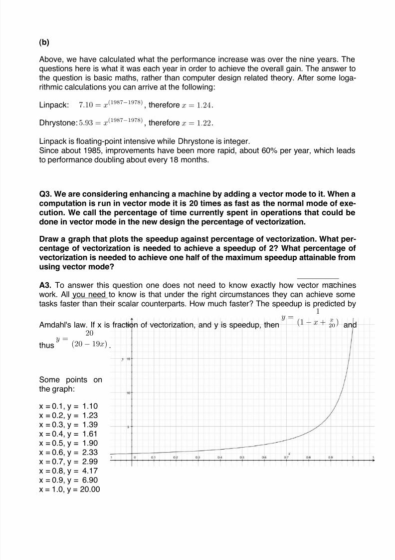
Q3. We are considering enhancing a machine by adding a vector mode to it. When acomputation is run in vector mode it is 20 times as fast as the normal mode of exe-cution. We call the percentage of time currently spent in operations that could bedone in vector mode in the new design the percentage of vectorization.
Draw a graph that plots the speedup against percentage of vectorization. What per-centage of vectorization is needed to achieve a speedup of 2? What percentage ofvectorization is needed to achieve one half of the maximum speedup attainable fromusing vector mode?
A3. To answer this question one does not need to know exactly how vector machines
work. All you need to know is that under the right circumstances they can achieve sometasks faster than their scalar counterparts. How much faster? The speedup is predicted by
Amdahl's law. If x is fraction of vectorization, and y is speedup, theny =
1
(1− x+ x
20) and
thusy =
20
(20− 19x) .
Some points on
the graph:
x = 0.1, y = 1.10x = 0.2, y = 1.23x = 0.3, y = 1.39x = 0.4, y = 1.61x = 0.5, y = 1.90x = 0.6, y = 2.33x = 0.7, y = 2.99x = 0.8, y = 4.17x = 0.9, y = 6.90
x = 1.0, y = 20.00

8/7/2019 s1_intro
http://slidepdf.com/reader/full/s1intro 4/6
You need slightly more than 50% vectorization for a speedup of 2; you need slightly lessthan 95% vectorization for a speedup of 10. As you can see from the graph, to achieveconsiderable speedup in the execution of a program, you must make sure that as much aspossible of the program can be executed using the vector mode. Otherwise the wholething is not worth the trouble. Vector machines are not cost effective unless the percentageof vectorization is high. The problem is that the achievement of this goal usually requires
significant rewriting of the program.
Q4. Consider a vector machine as in question 3, but assume that the vector mode is100 times as fast as the normal (scalar) mode. What percentage of vectorization isneeded to achieve a speedup of 2?
A4. At 50% vectorization, the speedup on this machine is 1.98, so the answer is still"slightly more than 50%", although the term "slightly" more now covers somewhat fewerpercentage points.
The implication is that the maximum speedup you can get from vectorization, or any othertechnique that speeds up only some parts of programs, is not as important as the fractionof the program to which the optimization is applicable.
Q5. The Sun 4/110 is about five times as fast on most things than the Sun 3/50.However, the 3/50 has multiply hardware while the 4/110 does not, so multiplicationis four times as fast on the 3/50 than on the 4/110.
Assume that the relative performance of the two machines when the application
program spends none of its time on multiplication is 5 to 1. What is their relativeperformance when the application spends 5% of its time on multiplication on the 3/ 50? How about 10%, 20%, 50%?
A5. The required formula is a variant of the one associated with Amdahl's law; you can de-rive it quite easily simply by writing down the time required for each part of the program.
If the 3/50 spends a fraction f of its time doing things other than multiplication, then the
time taken by the 4/110 to do the same will bef 5 . Given that we are measuring time as a
fraction of the total time taken for the application to complete, the remainder of the time,
that is the time doing multiplication, is1− f
. During that time the 3/50 is actually four timesfaster, hence the time for the 4/110 to do the same is (1− f ) ∗ 4 .The overall time for the 4/110 to complete the same application as the 3/50 is
(1 − f ) ∗ 4 +f
5 , hence
speedup =old time
new time=
1
(1 − f ) ∗ 4 + f 5 .
When f = 1 , the speedup is of course 5 (400% improvement). On the other hand, if f = 0,that is only multiplication is done, we get speedup = 0.25, or in other words it takes 4 timeslonger to do things. This is because as the question stated, the 4/110 is four time slowerdoing multiplication than the 3/50.

8/7/2019 s1_intro
http://slidepdf.com/reader/full/s1intro 5/6

8/7/2019 s1_intro
http://slidepdf.com/reader/full/s1intro 6/6
speedup =1
1−f 4
+ 5f speedup =
old time
new time=
1
(1 − f ) ∗ 4 + f 5


