S UITE 3 M NJ 07430 P F : 201.684.0066 AX · Coax Cable: Three (3) 1-5/8” Æ cables running on...
103
April 20, 2018 Melanie A. Bachman Executive Director Connecticut Siting Council 10 Franklin Square New Britain, CT 06051 T-Mobile Northeast LLC – CTHA174A Tower Share Application 33 Mitchell Drive, Manchester, CT 06040 Latitude- 41.79730280 Longitude- -72.51194400 Dear Ms. Bachman, This letter and attachments are submitted on behalf of T-Mobile Northeast LLC (“T-Mobile”). T-Mobile plans to install antennas and related equipment at the tower site located at 33 Mitchell Drive in Manchester, Connecticut. This tower was originally approved by the Town of Manchester via Special Exception Application on November 19, 2012. T-Mobile will install twelve (12) 600/700/1900/2100 MHz panel antennas, one (1) microwave dish antenna, four (4) tower-mounted amplifiers, and four (4) RRHs at the 140’ level of the existing 170’ lattice tower. Four (4) hybrid cables and nine (9) coax cables will also be installed. T-Mobile’s equipment cabinets will be placed on a new concrete pad within the existing ground facility. Included are plans by Centek Engineering, dated March 28, 2018, depicting the planned changes and attached as Exhibit A. Also included is a structural analysis prepared by Centek Engineering, dated March 6, 2018, confirming that the existing tower is structurally capable of supporting the proposed equipment. This is attached and detailed in Exhibit B. Please accept this letter as notification pursuant to Regulations of Connecticut State Agencies 16-50aa, of T-Mobile’s intent to share a telecommunications facility pursuant to R.C.S.A. 16-50j-88. In accordance with R.C.S.A., a copy of this letter is being sent to Jay Moran, Mayor of the Town of Manchester, as well as the tower and property owner, Mitchell Drive LLC. Please see the attached letter from Mitchell Drive LLC authorizing the proposed shared use of this facility attached as Exhibit C. A copy of this submission is also being sent to Gary Anderson, Director of Planning and Economic Development for the Town of Manchester. The planned modifications of the facility fall squarely within those activities explicitly provided for in R.C.S.A. 16-50j-89. 1. The proposed modification will not result in an increase in the height of the existing structure. The top of the lattice tower is 170’; T-Mobile’s proposed antennas will be located at a center line height of 140’. 10 INDUSTRIAL AVE, SUITE 3 MAHWAH NJ 07430 PHONE: 201.684.0055 FAX: 201.684.0066
Transcript of S UITE 3 M NJ 07430 P F : 201.684.0066 AX · Coax Cable: Three (3) 1-5/8” Æ cables running on...

April 20, 2018
Melanie A. Bachman
Executive Director
Connecticut Siting Council
10 Franklin Square
New Britain, CT 06051
T-Mobile Northeast LLC – CTHA174A
Tower Share Application
33 Mitchell Drive, Manchester, CT 06040
Latitude- 41.79730280
Longitude- -72.51194400
Dear Ms. Bachman,
This letter and attachments are submitted on behalf of T-Mobile Northeast LLC (“T-Mobile”). T-Mobile
plans to install antennas and related equipment at the tower site located at 33 Mitchell Drive in Manchester,
Connecticut. This tower was originally approved by the Town of Manchester via Special Exception Application
on November 19, 2012.
T-Mobile will install twelve (12) 600/700/1900/2100 MHz panel antennas, one (1) microwave dish
antenna, four (4) tower-mounted amplifiers, and four (4) RRHs at the 140’ level of the existing 170’ lattice
tower. Four (4) hybrid cables and nine (9) coax cables will also be installed. T-Mobile’s equipment cabinets
will be placed on a new concrete pad within the existing ground facility. Included are plans by Centek
Engineering, dated March 28, 2018, depicting the planned changes and attached as Exhibit A. Also included is
a structural analysis prepared by Centek Engineering, dated March 6, 2018, confirming that the existing tower is
structurally capable of supporting the proposed equipment. This is attached and detailed in Exhibit B.
Please accept this letter as notification pursuant to Regulations of Connecticut State Agencies 16-50aa,
of T-Mobile’s intent to share a telecommunications facility pursuant to R.C.S.A. 16-50j-88. In accordance with
R.C.S.A., a copy of this letter is being sent to Jay Moran, Mayor of the Town of Manchester, as well as the
tower and property owner, Mitchell Drive LLC. Please see the attached letter from Mitchell Drive LLC
authorizing the proposed shared use of this facility attached as Exhibit C. A copy of this submission is also
being sent to Gary Anderson, Director of Planning and Economic Development for the Town of Manchester.
The planned modifications of the facility fall squarely within those activities explicitly provided for in
R.C.S.A. 16-50j-89.
1. The proposed modification will not result in an increase in the height of the existing structure. The top
of the lattice tower is 170’; T-Mobile’s proposed antennas will be located at a center line height of 140’.
10 INDUSTRIAL AVE, SUITE 3 MAHWAH NJ 07430 PHONE: 201.684.0055 FAX: 201.684.0066

2. The proposed modifications will not result in the increase of the site boundary as depicted on the
attached site plan.
3. The proposed modifications will not increase noise levels at the facility by six decibels or more, or to
levels that exceed local and state criteria. T-Mobile’s plans include the installation of an emergency
back-up generator; noise associated with this installation is exempt from State and local noise standards.
The incremental effect of the proposed changes will be negligible.
4. The operation of the proposed antennas will not increase radio frequency emissions at the facility to a
level at or above the Federal Communications Commission safety standard. As indicated in the attached
power density calculations, the combined site operations will result in a total power density of 3.90%, as
evidenced by Exhibit D.
Connecticut General Statutes 16-50aa indicates that the Council must approve the shared use of a
telecommunications facility provided it finds the shared use is technically, legally, environmentally, and
economically feasible and meets public safety concerns. As demonstrated in this letter, T-Mobile
respectfully submits that the shared use of this facility satisfies these criteria.
A. Technical Feasibility. The existing lattice tower has been deemed structurally capable of supporting T-
Mobile’s proposed loading. The structural analysis is included as Exhibit B.
B. Legal Feasibility. As referenced above, C.G.S. 16-50aa has been authorized to issue orders approving
the shared use of an existing tower such as this lattice tower in Manchester. Under the authority granted
to the Council, an order of the Council approving the requested shared use would permit T-Mobile to
obtain a building permit for the proposed installation. Further, a Letter of Authorization is included as
Exhibit C, authorizing T-Mobile to file this application for shared use.
C. Environmental Feasibility. The proposed shared use of this facility would have minimal environmental
impact. The installation of T-Mobile equipment at the 140’ level of the existing 170’ tower would have
an insignificant visual impact on the area around the tower. T-Mobile’s ground equipment would be
installed on a concrete pad within the existing facility compound. T-Mobile’s shared use would
therefore not cause any significant alteration in the physical or environmental characteristics of the
existing site. Additionally, as evidenced by Exhibit D, the proposed antennas would not increase radio
frequency emissions to a level at or above the Federal Communications Commission safety standard.
D. Economic Feasibility. T-Mobile will be entering into an agreement with the owner of this facility to
mutually agreeable terms. As previously mentioned, the Letter of Authorization has been provided by
the owner to assist T-Mobile with this tower sharing application.
E. Public Safety Concerns. As discussed above, the lattice tower is structurally capable of supporting T-
Mobile’s proposed loading. T-Mobile is not aware of any public safety concerns relative to the proposed
sharing of the existing tower. T-Mobile’s intentions of providing new and improved wireless service
through the shared use of this facility is expected to enhance the safety and welfare of local residents and
individuals traveling through Manchester and nearby the facility.
Sincerely,
Kyle Richers Kyle Richers CC: Jay Moran- First Selectmen
Transcend Wireless Mitchell Drive LLC- Owner
10 Industrial Ave., Suite 3 Gary Anderson- Zoning Official
Mahwah, New Jersey
908-447-4716

TITLESHEET
1 13
REV.DESCRIPTIONSHT. NO.
PROJECTLOCATION
NORTH
MANCHESTER, CT 06040
WIRELESS COMMUNICATIONS FACILITY

DESIGN BASISAND STRUCTURALSPECIFICATIONS
2 13

SITE LOCATIONPLAN
3 13

13
COMPOUND PLAN,EQUIP. LAYOUTAND ANTENNA
4
MOUNTING CONFIG.

135
ELEVATIONS
±±

13
EQUIPMENTDETAILS
6
ALPHA/BETA/GAMMA/DELTA ANTENNA
FRONT SIDE
RRH (REMOTE RADIO HEAD)
AIR-32 KRDAIR-21 KRC
EQUIPMENT CABINET
DIESEL FUELED BACKUP POWER GENERATOR
ISOMETRIC VIEW BOTTOM VIEW

137
TYPICALDETAILS
EXTERIOR LIGHT

138
STRUCTURALDETAILS
S t r u c t u r a l A n a l y s i s R e p o r t
1 7 0 - f t E x i s t i n g V a l m o n t L a t t i c e T o w e r
S i t e R e f : C T H A 1 7 4
3 3 M i t c h e l l D r i v eM a n c h e s t e r , C T
C E N T E K P r o j e c t N o . 1 8 0 3 4 . 0 0
D a t e : M a r c h 6 , 2 0 1 8
Prepared for:T-Mobile USA
35 Griff in RoadBloomf ield, CT 06002

CENTEK Engineering, Inc.Structural Analysis - 170-ft Valmont Lattice TowerT-Mobile Antenna Installation ~ CTHA174Manchester, CTMarch 6, 2018
TABLE OF CONTENTS TOC-1
T a b l e o f C o n t e n t sSECTION 1 – REPORT
§ INTRODUCTION
§ ANTENNA AND APPURTENANCE SUMMARY
§ PRIMARY ASSUMPTIONS USED IN THE ANALYSIS
§ ANALYSIS
§ TOWER LOADING
§ TOWER CAPACITY
§ FOUNDATION AND ANCHORS
§ CONCLUSION
SECTION 2 – CONDITIONS & SOFTWARE
§ STANDARD ENGINEERING CONDITIONS
§ GENERAL DESCRIPTION OF STRUCTURAL ANALYSIS PROGRAM
SECTION 3 – CALCULATIONS
§ tnxTower INPUT/OUTPUT SUMMARY
§ tnxTower FEED LINE PLAN
§ tnxTower FEED LINE DISTRIBUTION
§ tnxTower DETAILED OUTPUT
§ FOUNDATION ANALYSIS
SECTION 4 – REFERENCE MATERIALS
§ EQUIPMENT CUT SHEETS

CENTEK Engineering, Inc.Structural Analysis - 170-ft Valmont Lattice TowerT-Mobile Antenna Installation ~ CTHA174Manchester, CTMarch 6, 2018
REPORT SECTION 1-1
I n t r o d u c t i o nThe purpose of this report is to summarize the results of the non-linear, P-∆ structural analysisof the antenna installation proposed by T-Mobile on the existing lattice tower located inManchester, Connecticut.
The host tower is a 170-ft, three legged, lattice tower originally manufactured by Valmont engfile no. A-175553 dated 9/20/12. The tower geometry, structure member sizes and foundationinformation were taken from the aforementioned tower design documents.
Antenna and appurtenance information were obtained from the aforementioned tower designdrawings, a previous structural analysis prepared by All-Points Technology project no.CT141NB9160, dated October 4, 2017 and visual verification from grade conducted by Centekpersonnel on February 20, 2018.
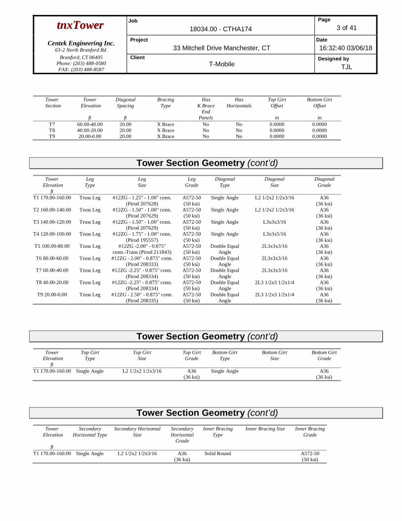
The tower consists of nine (9) vertical sections consisting of truss legs conforming to ASTMA572 GR. 50 with diagonal steel angle bracing conforming to ASTM A36. The vertical towersections are connected by bolted flange plates with the diagonal and horizontal bracing to pipelegs consisting of bolted connections. The width of the tower face is 7-ft at the top and 24-ft atthe bottom.
A n t e n n a a n d A p p u r t e n a n c e S u m m a r yThe existing, proposed and future loads considered in this analysis consist of the following:
§ Future Carrier (Reserved):Antennas: Twelve (12) 6’x1’ panel antennas mounted on (3) 12-ft V-Frames with a RADcenter elevation of ±170-ft above grade level.
Coax Cables: Twelve (12) 1-5/8” Æ coax cables running on a leg/face of the existingtower as specified in Section 3 of this report.
§ Unknown (Reserved):Antennas: Three (3) 6-ft Microwave dishes leg mounted with a RAD center elevation of±165-ft above grade level.
Coax Cable: Three (3) 1-5/8” Æ cables running on the leg of the existing tower asspecified in Section 3 of this report.
§ Unknown (Reserved):Antennas: One (1) Shively Labs 6812 leg mounted with a RAD center elevation of ±160-ft above grade level.
Coax Cable: One (1) 1-5/8” Æ cables running on the leg of the existing tower asspecified in Section 3 of this report.
§ Unknown (Reserved):Antennas: One (1) Shively Labs 6812 leg mounted with a RAD center elevation of ±155-ft above grade level.
Coax Cable: One (1) 1-5/8” Æ cables running on the leg of the existing tower asspecified in Section 3 of this report.

CENTEK Engineering, Inc.Structural Analysis - 170-ft Valmont Lattice TowerT-Mobile Antenna Installation ~ CTHA174Manchester, CTMarch 6, 2018
REPORT SECTION 1-2
§ Unknown (Reserved):Antennas: Two (2) 4-ft Microwave dishes and one (1) 2-ft Microwave dish leg mountedwith a RAD center elevation of ±150-ft above grade level.
Coax Cable: Three (3) 1-5/8” Æ cables running on the leg of the existing tower asspecified in Section 3 of this report.
§ VERIZON (Proposed):Antennas: Twelve (12) Andrew SBNHH-1D65B panel antennas, three (3) Alcatel-LucentRRH2x60-LTE remote radio heads, three (3) Alcatel-Lucent RRH4x45/2x90-AWSremote radio heads, three (3) Alcatel-Lucent RRH2x60-PCS remote radio heads and two(2) RFS DB-T1-6Z-8AB-0Z distribution boxes mounted on (3) 12-ft V-Frames with a RADcenter elevation of ±100-ft above grade level.
Coax Cables: Two (2) 1-5/8” Æ fiber cables running on a leg/face of the existing tower asspecified in Section 3 of this report.
§ T-MOBILE (PROPOSED):Antennas: Four (4) Ericsson AIR32 panel antennas, four (4) Ericcson AIR21panel antennas, four (4) RFS APXVAARR24-43 panel antennas, four (4)Ericsson KRY 112-144 TMAs, twelve (12) Ericsson 4449 B12,B71 remote radioheads and one (1) Commscope SC2-W100AB microwave dish mounted on one(1) custom 4-sided sector frame with a RAD center elevation of 140-ft AGL.Coax Cables: Four (4) 1-5/8” Æ fiber cables, eight (8) 1-5/8” Æ coax cables andone (1) 1/2” Æ coax cable running on a leg/face of the existing tower.

CENTEK Engineering, Inc.Structural Analysis - 170-ft Valmont Lattice TowerT-Mobile Antenna Installation ~ CTHA174Manchester, CTMarch 6, 2018
REPORT SECTION 1-3
P r i m a r y A s s u m p t i o n s U s e d i n t h e A n a l y s i s
§ The tower structure’s theoretical capacity not including any assessment of thecondition of the tower.
§ The tower carries the horizontal and vertical loads due to the weight of antennas, iceload and wind.
§ Tower is properly installed and maintained.
§ Tower is in plumb condition.
§ Tower loading for antennas and mounts as listed in this report.
§ All bolts are appropriately tightened providing the necessary connection continuity.
§ All welds are fabricated with ER-70S-6 electrodes.
§ All members are assumed to be as specified in the original tower design documents.
§ All members are “hot dipped” galvanized in accordance with ASTM A123 and ASTMA153 Standards.
§ All member protective coatings are in good condition.
§ All tower members were properly designed, detailed, fabricated, installed and havebeen properly maintained since erection.
§ Any deviation from the analyzed antenna loading will require a new analysis forverification of structural adequacy.

CENTEK Engineering, Inc.Structural Analysis - 170-ft Valmont Lattice TowerT-Mobile Antenna Installation ~ CTHA174Manchester, CTMarch 6, 2018
REPORT SECTION 1-4
A n a l y s i sThe existing tower was analyzed using a comprehensive computer program entitled tnxTower.The program analyzes the tower, considering the worst case loading condition. The tower isconsidered as loaded by concentric forces along the tower, and the model assumes that thetower members are subjected to bending, axial, and shear forces.
The existing tower was analyzed for the controlling basic wind speed (3-second gust) with noice and the applicable wind and ice combination to determine stresses in members as perguidelines of TIA-222-G-2005 entitled “Structural Standard for Antenna Support Structures andAntennas”, the American Institute of Steel Construction (AISC) and the Manual of SteelConstruction; Load and Resistance Factor Design (LRFD).
The controlling wind speed is determined by evaluating the local available wind speed data asprovided in Appendix N of the CSBC1 and the wind speed data available in the TIA-222-G-2005Standard.
T o w e r L o a d i n g
Tower loading was determined by the basic wind speed as applied to projected surface areaswith modification factors per TIA-222-G-2005, gravity loads of the tower structure and itscomponents, and the application of 1.00” radial ice on the tower structure and its components.
Basic WindSpeed:
Manchester; v = 97 mph (3 secondgust)
[Appendix N of the 2016 CTBuilding Code]
Load Cases: Load Case 1; 97 mph wind speed w/no ice plus gravity load – used incalculation of tower stresses androtation.
[Appendix N of the 2016 CTBuilding Code]
Load Case 2; = 50 mph wind speedw/ 1.00” radial ice plus gravity load –used in calculation of tower stresses.
[Annex B of TIA-222-G-2005]
1 The 2012 International Building Code as amended by the 2016 Connecticut State Building Code (CSBC).

CENTEK Engineering, Inc.Structural Analysis - 170-ft Valmont Lattice TowerT-Mobile Antenna Installation ~ CTHA174Manchester, CTMarch 6, 2018
REPORT SECTION 1-5
T o w e r C a p a c i t y
§ Calculated stresses were found to be within allowable limits. In Load Case 2, pertnxTower “Section Capacity Table”, this tower was found to be at 94.5% of its totalcapacity.
F o u n d a t i o n a n d A n c h o r s
The existing foundation consists of three (3) 4.5’ Æ x 4.75’ tall reinforced concrete piers and one(1) 32.0’ square x 1.75’ thick reinforced concrete mat. The sub-grade conditions used in theanalysis of the existing foundation were obtained from the aforementioned manufacturersoriginal design documents. The tower legs are connected to the foundation by means of twelve
(12) 1Ӯ, ASTM F1554 Grade 105 anchor bolts per leg, embedded into the concrete foundationstructure.
§ The tower reactions developed from the governing Load Case 1 of the proposedreinforced tower condition were used in the verification of the foundation and anchorbolts:
Tower Section ElevationStress Ratio
(percentage ofcapacity)
Result
Leg (T8) 20’-0”- 40’-0” 63.8% PASS
Diagonal (T7) 40’-0”- 60’-0” 94.5% PASS
Leg Reactions Vector Proposed Tower Reactions
Leg
Shear 38 kipsCompression 326 kips
Uplift 276 kips
Base
Shear 62 kipsCompression 62 kips
Moment 6355 kip-ft

CENTEK Engineering, Inc.Structural Analysis - 170-ft Valmont Lattice TowerT-Mobile Antenna Installation ~ CTHA174Manchester, CTMarch 6, 2018
REPORT SECTION 1-6
§ The anchor bolts were found to be within allowable limits.
§ The foundation was found to be within allowable limits.
Note 1: Minimum required Factor of Safety (FS) of 1.0 required per TIA-222-G section 9.4
C o n c l u s i o n
This analysis shows that the subject tower is adequate to support the proposed antenna
configuration.
The analysis is based, in part, on the information provided to this office by T-Mobile. If theexisting conditions are different than the information in this report, Centek Engineering, Inc.must be contacted for resolution of any potential issues.
Please feel free to call with any questions or comments.
Respectfully Submitted by:
Timothy J. Lynn, PEStructural Engineer
Tower Section ComponentStress Ratio
(percentage ofcapacity)
Result
Anchor Bolts Tension 39.2% PASS
Foundation Type DesignLimit
AllowableLimit/FS
ProposedLoading Result
Reinforced ConcretePiers and Mat
Ultimate BearingPressure
6.00 ksf 2.22 ksf PASS
Overturning 1.00(1)
1.61 PASS

CENTEK Engineering, Inc.Structural Analysis - 170-ft Valmont Lattice TowerT-Mobile Antenna Installation ~ CTHA174Manchester, CTMarch 6, 2018
REPORT SECTION 2-1
S t a n d a r d C o n d i t i o n s f o r F u r n i s h i n g o fP r o f e s s i o n a l E n g i n e e r i n g S e r v i c e s o nE x i s t i n g S t r u c t u r e s
All engineering services are performed on the basis that the information used is current andcorrect. This information may consist of, but is not necessarily limited to:
§ Information supplied by the client regarding the structure itself, its foundations, the soilconditions, the antenna and feed line loading on the structure and its components, orother relevant information.
§ Information from the field and/or drawings in the possession of Centek Engineering, Inc.or generated by field inspections or measurements of the structure.
§ It is the responsibility of the client to ensure that the information provided to CentekEngineering, Inc. and used in the performance of our engineering services is correct andcomplete. In the absence of information to the contrary, we assume that all structureswere constructed in accordance with the drawings and specifications and are in an un-corroded condition and have not deteriorated. It is therefore assumed that its capacityhas not significantly changed from the “as new” condition.
§ All services will be performed to the codes specified by the client, and we do not imply tomeet any other codes or requirements unless explicitly agreed in writing. If wind and iceloads or other relevant parameters are to be different from the minimum valuesrecommended by the codes, the client shall specify the exact requirement. In theabsence of information to the contrary, all work will be performed in accordance with thelatest revision of ANSI/ASCE10 & ANSI/EIA-222
§ All services performed, results obtained, and recommendations made are in accordancewith generally accepted engineering principles and practices. Centek Engineering, Inc.is not responsible for the conclusions, opinions and recommendations made by othersbased on the information we supply.

CENTEK Engineering, Inc.Structural Analysis - 170-ft Valmont Lattice TowerT-Mobile Antenna Installation ~ CTHA174Manchester, CTMarch 6, 2018
REPORT SECTION 2-2
G E N E R A L D E S C R I P T I O N O F S T R U C T U R A LA N A L Y S I S P R O G R A M
tnxTower, is an integrated structural analysis and design software package for Designedspecifically for the telecommunications industry, tnxTower, formerly RISA Tower, automatesmuch of the tower analysis and design required by the TIA/EIA 222 Standard.
tnxTower Features:
§ tnxTower can analyze and design 3- and 4-sided guyed towers, 3- and 4-sided self-supporting towers and either round or tapered ground mounted poles with or withoutguys.
§ The program analyzes towers using the TIA-222-G (2005) standard or any of theprevious TIA/EIA standards back to RS-222 (1959). Steel design is checked using theAISC ASD 9th Edition or the AISC LRFD specifications.
§ Linear and non-linear (P-delta) analyses can be used in determining displacements andforces in the structure. Wind pressures and forces are automatically calculated.
§ Extensive graphics plots include material take-off, shear-moment, leg compression,displacement, twist, feed line, guy anchor and stress plots.
§ tnxTower contains unique features such as True Cable behavior, hog rod take-up,foundation stiffness and much more.

Centek Engineering Inc. 63-2 North Branford Rd.
Branford, CT 06405 Phone: (203) 488-0580
FAX: (203) 488-8587
Job: 18034.00 - CTHA174 Project: 33 Mitchell Drive Manchester, CT Client: T-Mobile Drawn by: TJL App'd:
Code: TIA-222-G Date: 03/06/18 Scale: NTS Path:
J:\Jobs\1803400.WI\04_Structural\Backup Documentation\ERI Files\170' Valmont Lattice Tower.eri Dwg No. E-1
170.0 ft
160.0 ft
140.0 ft
120.0 ft
100.0 ft
80.0 ft
60.0 ft
40.0 ft
20.0 ft
0.0 ft
REACTIONS - 97 mph WINDTORQUE 11 kip-ft
62 KSHEAR
6355 kip-ftMOMENT
62 KAXIAL
50 mph WIND - 1.0000 in ICETORQUE 4 kip-ft
18 KSHEAR
1843 kip-ftMOMENT
218 KAXIAL
SHEAR: 34 KUPLIFT: -276 K
SHEAR: 38 KDOWN: 326 K
MAX. CORNER REACTIONS AT BASE:
ARE FACTOREDALL REACTIONS
Section
T1
T2
T3
T4
T5
T6
T7
T8
T9
Legs
A#12Z
G-
1.5
0"
-1.0
0"
conn.(P
irod
207629)
#12Z
G-
1.7
5"
-1.0
0"
conn.(P
irod
195557)
B#12Z
G-
2.0
0"
-0.8
75"
conn.(P
irod
208333)
#12Z
G-2
.25"
-0.8
75"
conn.(P
irod
208334)
#12Z
G-
2.5
0"
-0.8
75"
conn.(P
irod
208335)
Leg
Gra
de
A572-5
0
Dia
gonals
L2
1/2
x2
1/2
x3/1
6L3x3x3/1
6L3x3x5/1
62L3x3x3/1
62L3
1/2
x3
1/2
x1/4
Dia
gonalG
rade
A36
Top
Girts
L2
1/2
x2
1/2
x3/1
6N
.A.
Sec.H
orizonta
lsL2
1/2
x2
1/2
x3/1
6N
.A.
Face
Wid
th(f
t)7
810
12
14
16
18
20
22
24
#P
anels
@(f
t)7
@10
5@
20
Weig
ht(K
)1.0
2.2
2.3
3.2
4.1
4.2
4.7
5.5
6.2
33.4
15' Lighting Rod 170Beacon 170(4) 6'x1' Panel Antenna (Future Carrier) 170(4) 6'x1' Panel Antenna (Future Carrier) 170(4) 6'x1' Panel Antenna (Future Carrier) 170SitePro VFA12-HD (Future Carrier) 170SitePro VFA12-HD (Future Carrier) 170SitePro VFA12-HD (Future Carrier) 1706-ft Dish 1656-ft Dish 1656-ft Dish 1656812 1606812 1554-ft Dish 1504-ft Dish 1502-ft dish 150APXVAARR24-43 (T-Mobile Proposed) 140AIR32 (T-Mobile Proposed) 140AIR21 B2A/B4P (T-Mobile Proposed) 140APXVAARR24-43 (T-Mobile Proposed) 140AIR32 (T-Mobile Proposed) 140AIR21 B2A/B4P (T-Mobile Proposed) 140APXVAARR24-43 (T-Mobile Proposed) 140AIR32 (T-Mobile Proposed) 140AIR21 B2A/B4P (T-Mobile Proposed) 140APXVAARR24-43 (T-Mobile Proposed) 140AIR32 (T-Mobile Proposed) 140AIR21 B2A/B4P (T-Mobile Proposed) 140KRY 112-144-1 TMA (T-Mobile Proposed) 140KRY 112-144-1 TMA (T-Mobile Proposed) 140KRY 112-144-1 TMA (T-Mobile Proposed) 140KRY 112-144-1 TMA (T-Mobile Proposed) 140(4) 4449 B12,B71 (T-Mobile Proposed) 140(4) 4449 B12,B71 (T-Mobile Proposed) 140(4) 4449 B12,B71 (T-Mobile Proposed) 140Custom 4-Sided Sector Mount (T-MobileProposed)
140SC2-W100AB (T-Mobile Proposed) 140RRH2x60-07-U (Verizon) 100RRH2x60-PCS (Verizon) 100RRH4x45/2x90-AWS (Verizon) 100RRH4x45/2x90-AWS (Verizon) 100RRH4x45/2x90-AWS (Verizon) 100DB-T1-6Z-8AB-0Z (Verizon) 100DB-T1-6Z-8AB-0Z (Verizon) 100SitePro VFA12-HD (Verizon) 100SitePro VFA12-HD (Verizon) 100SitePro VFA12-HD (Verizon) 100RRH2x60-07-U (Verizon) 100(4) SBNHH-1D65B (Verizon) 100(4) SBNHH-1D65B (Verizon) 100(4) SBNHH-1D65B (Verizon) 100RRH2x60-07-U (Verizon) 100RRH2x60-PCS (Verizon) 100RRH2x60-PCS (Verizon) 100DESIGNED APPURTENANCE LOADINGTYPE TYPEELEVATION ELEVATION
15' Lighting Rod 170
Beacon 170
(4) 6'x1' Panel Antenna (Future Carrier) 170
(4) 6'x1' Panel Antenna (Future Carrier) 170
(4) 6'x1' Panel Antenna (Future Carrier) 170
SitePro VFA12-HD (Future Carrier) 170
SitePro VFA12-HD (Future Carrier) 170
SitePro VFA12-HD (Future Carrier) 170
6-ft Dish 165
6-ft Dish 165
6-ft Dish 165
6812 160
6812 155
4-ft Dish 150
4-ft Dish 150
2-ft dish 150
APXVAARR24-43 (T-Mobile Proposed) 140
AIR32 (T-Mobile Proposed) 140
AIR21 B2A/B4P (T-Mobile Proposed) 140
APXVAARR24-43 (T-Mobile Proposed) 140
AIR32 (T-Mobile Proposed) 140
AIR21 B2A/B4P (T-Mobile Proposed) 140
APXVAARR24-43 (T-Mobile Proposed) 140
AIR32 (T-Mobile Proposed) 140
AIR21 B2A/B4P (T-Mobile Proposed) 140
APXVAARR24-43 (T-Mobile Proposed) 140
AIR32 (T-Mobile Proposed) 140
AIR21 B2A/B4P (T-Mobile Proposed) 140
KRY 112-144-1 TMA (T-Mobile Proposed) 140
KRY 112-144-1 TMA (T-Mobile Proposed) 140
KRY 112-144-1 TMA (T-Mobile Proposed) 140
KRY 112-144-1 TMA (T-Mobile Proposed) 140
(4) 4449 B12,B71 (T-Mobile Proposed) 140
(4) 4449 B12,B71 (T-Mobile Proposed) 140
(4) 4449 B12,B71 (T-Mobile Proposed) 140
Custom 4-Sided Sector Mount (T-MobileProposed)
140
SC2-W100AB (T-Mobile Proposed) 140
RRH2x60-07-U (Verizon) 100
RRH2x60-PCS (Verizon) 100
RRH4x45/2x90-AWS (Verizon) 100
RRH4x45/2x90-AWS (Verizon) 100
RRH4x45/2x90-AWS (Verizon) 100
DB-T1-6Z-8AB-0Z (Verizon) 100
DB-T1-6Z-8AB-0Z (Verizon) 100
SitePro VFA12-HD (Verizon) 100
SitePro VFA12-HD (Verizon) 100
SitePro VFA12-HD (Verizon) 100
RRH2x60-07-U (Verizon) 100
(4) SBNHH-1D65B (Verizon) 100
(4) SBNHH-1D65B (Verizon) 100
(4) SBNHH-1D65B (Verizon) 100
RRH2x60-07-U (Verizon) 100
RRH2x60-PCS (Verizon) 100
RRH2x60-PCS (Verizon) 100
SYMBOL LISTMARK MARKSIZE SIZE
A #12ZG - 1.25" - 1.00" conn. (Pirod 207628) B #12ZG -2.00" - 0.875" conn.-Trans (Pirod 211843)
MATERIAL STRENGTHGRADE GRADEFy FyFu Fu
A572-50 50 ksi 65 ksi A36 36 ksi 58 ksi
TOWER DESIGN NOTES1. Tower designed for Exposure C to the TIA-222-G Standard.2. Tower designed for a 97 mph basic wind in accordance with the TIA-222-G Standard.3. Tower is also designed for a 50 mph basic wind with 1.00 in ice. Ice is considered to increase in thickness with height.4. Deflections are based upon a 60 mph wind.5. Tower Structure Class II.6. Topographic Category 1 with Crest Height of 0.00 ft7. TOWER RATING: 94.5%

Centek Engineering Inc. 63-2 North Branford Rd.
Branford, CT 06405 Phone: (203) 488-0580
FAX: (203) 488-8587
Job: 18034.00 - CTHA174 Project: 33 Mitchell Drive Manchester, CT Client: T-Mobile Drawn by: TJL App'd:
Code: TIA-222-G Date: 03/06/18 Scale: NTS Path:
J:\Jobs\1803400.WI\04_Structural\Backup Documentation\ERI Files\170' Valmont Lattice Tower.eri Dwg No. E-7
Feed Line Plan
Round Flat App In Face App Out Face Truss-Leg
A B
C(4) H
YBRIF
LEX
1-5/
8"(T
-Mob
ilePro
pose
d)
(2) H
YBRIF
LEX
1-5/
8"(V
erizon
)
(12) 1 5/8 (Future)
(8) 1 5/8(8
) 15/
8(T
-Mob
ilePro
pose
d)
1/2
(T-M
obile
Propo
sed)

Centek Engineering Inc. 63-2 North Branford Rd.
Branford, CT 06405 Phone: (203) 488-0580
FAX: (203) 488-8587
Job: 18034.00 - CTHA174 Project: 33 Mitchell Drive Manchester, CT Client: T-Mobile Drawn by: TJL App'd:
Code: TIA-222-G Date: 03/06/18 Scale: NTS Path:
J:\Jobs\1803400.WI\04_Structural\Backup Documentation\ERI Files\170' Valmont Lattice Tower.eri Dwg No. E-7
Feed Line Distribution Chart0' - 170'
Round Flat App In Face App Out Face Truss Leg
Face A
160.00
140.00
120.00
100.00
80.00
60.00
40.00
20.00
0.00
170.00
Elev
atio
n(ft
)
(12)
15/8
(Futu
re)
Face B
140.00
100.00
140.00140.00
(8)
15/8
Face C
160.00
140.00
120.00
100.00
80.00
60.00
40.00
20.00
0.00
170.00
140.00
100.00
140.00140.00
(4)
HY
BR
IFLE
X1-5
/8"
(T-M
obile
Pro
posed)
(2)
HY
BR
IFLE
X1-5
/8"
(Verizon)
(8)
15/8
(T-M
obile
Pro
posed)
1/2
(T-M
obile
Pro
posed)

ttnnxxTToowweerr Job18034.00 - CTHA174
Page1 of 41
Centek Engineering Inc.63-2 North Branford Rd.
Project33 Mitchell Drive Manchester, CT
Date16:32:40 03/06/18
Branford, CT 06405Phone: (203) 488-0580FAX: (203) 488-8587
ClientT-Mobile
Designed byTJL
Tower Input Data
The main tower is a 3x free standing tower with an overall height of 170.00 ft above the ground line.
The base of the tower is set at an elevation of 0.00 ft above the ground line.The face width of the tower is 7.00 ft at the top and 24.00 ft at the base.
This tower is designed using the TIA-222-G standard.
The following design criteria apply:
Basic wind speed of 97 mph.
Structure Class II.
Exposure Category C.
Topographic Category 1.
Crest Height 0.00 ft.
Nominal ice thickness of 1.0000 in.
Ice thickness is considered to increase with height.
Ice density of 56 pcf.
A wind speed of 50 mph is used in combination with ice.Temperature drop of 50 °F.
Deflections calculated using a wind speed of 60 mph.
A non-linear (P-delta) analysis was used.
Pressures are calculated at each section.
Stress ratio used in tower member design is 1.
Local bending stresses due to climbing loads, feed line supports, and appurtenance mounts are not considered.
Options√ Consider Moments - Legs Distribute Leg Loads As Uniform Use ASCE 10 X-Brace Ly Rules
Consider Moments - Horizontals Assume Legs Pinned √ Calculate Redundant Bracing Forces
Consider Moments - Diagonals √ Assume Rigid Index Plate Ignore Redundant Members in FEA
Use Moment Magnification √ Use Clear Spans For Wind Area √ SR Leg Bolts Resist Compression
√ Use Code Stress Ratios √ Use Clear Spans For KL/r √ All Leg Panels Have Same Allowable
√ Use Code Safety Factors - Guys Retension Guys To Initial Tension Offset Girt At Foundation
Escalate Ice Bypass Mast Stability Checks √ Consider Feed Line Torque
Always Use Max Kz √ Use Azimuth Dish Coefficients Include Angle Block Shear Check
Use Special Wind Profile √ Project Wind Area of Appurt. Use TIA-222-G Bracing Resist. Exemption
√ Include Bolts In Member Capacity Autocalc Torque Arm Areas Use TIA-222-G Tension Splice Exemption
Leg Bolts Are At Top Of Section Add IBC .6D+W Combination Poles
√ Secondary Horizontal Braces Leg √ Sort Capacity Reports By Component Include Shear-Torsion Interaction
Use Diamond Inner Bracing (4 Sided) Triangulate Diamond Inner Bracing Always Use Sub-Critical Flow
√ SR Members Have Cut Ends Treat Feed Line Bundles As Cylinder Use Top Mounted Sockets
SR Members Are Concentric

ttnnxxTToowweerr Job18034.00 - CTHA174
Page2 of 41
Centek Engineering Inc.63-2 North Branford Rd.
Project33 Mitchell Drive Manchester, CT
Date16:32:40 03/06/18
Branford, CT 06405Phone: (203) 488-0580FAX: (203) 488-8587
ClientT-Mobile
Designed byTJL
Leg BLeg C
Leg A
Face
AFac
eB
Face C
Triangular To wer
Wind Norma l
Wind 90
Wind 180
Z
X
Tower Section GeometryTower
SectionTower
Elevation
ft
AssemblyDatabase
Description SectionWidth
ft
Numberof
Sections
SectionLength
ftT1 170.00-160.00 7.00 1 10.00
T2 160.00-140.00 8.00 1 20.00
T3 140.00-120.00 10.00 1 20.00
T4 120.00-100.00 12.00 1 20.00
T5 100.00-80.00 14.00 1 20.00
T6 80.00-60.00 16.00 1 20.00
T7 60.00-40.00 18.00 1 20.00
T8 40.00-20.00 20.00 1 20.00
T9 20.00-0.00 22.00 1 20.00
Tower Section Geometry (cont’d)Tower
SectionTower
Elevation
ft
DiagonalSpacing
ft
BracingType
HasK Brace
EndPanels
HasHorizontals
Top GirtOffset
in
Bottom GirtOffset
inT1 170.00-160.00 10.00 X Brace No Yes 0.0000 0.0000
T2 160.00-140.00 10.00 X Brace No No 0.0000 0.0000
T3 140.00-120.00 10.00 X Brace No No 0.0000 0.0000
T4 120.00-100.00 10.00 X Brace No No 0.0000 0.0000
T5 100.00-80.00 20.00 X Brace No No 0.0000 0.0000
T6 80.00-60.00 20.00 X Brace No No 0.0000 0.0000
ttnnxxTToowweerr Job18034.00 - CTHA174
Page3 of 41
Centek Engineering Inc.63-2 North Branford Rd.
Project33 Mitchell Drive Manchester, CT
Date16:32:40 03/06/18
Branford, CT 06405Phone: (203) 488-0580FAX: (203) 488-8587
ClientT-Mobile
Designed byTJL
Tower Section
Tower Elevation
ft
DiagonalSpacing
ft
BracingType
HasK Brace
EndPanels
HasHorizontals
Top GirtOffset
in
Bottom GirtOffset
inT7 60.00-40.00 20.00 X Brace No No 0.0000 0.0000
T8 40.00-20.00 20.00 X Brace No No 0.0000 0.0000
T9 20.00-0.00 20.00 X Brace No No 0.0000 0.0000
Tower Section Geometry (cont’d)Tower
Elevationft
LegType
LegSize
LegGrade
DiagonalType
DiagonalSize
DiagonalGrade
T1 170.00-160.00 Truss Leg #12ZG - 1.25'' - 1.00'' conn.
(Pirod 207628)
A572-50
(50 ksi)
Single Angle L2 1/2x2 1/2x3/16 A36
(36 ksi)
T2 160.00-140.00 Truss Leg #12ZG - 1.50'' - 1.00'' conn.
(Pirod 207629)
A572-50
(50 ksi)
Single Angle L2 1/2x2 1/2x3/16 A36
(36 ksi)
T3 140.00-120.00 Truss Leg #12ZG - 1.50'' - 1.00'' conn.
(Pirod 207629)
A572-50
(50 ksi)
Single Angle L3x3x3/16 A36
(36 ksi)
T4 120.00-100.00 Truss Leg #12ZG - 1.75'' - 1.00'' conn.
(Pirod 195557)
A572-50
(50 ksi)
Single Angle L3x3x5/16 A36
(36 ksi)
T5 100.00-80.00 Truss Leg #12ZG -2.00'' - 0.875''
conn.-Trans (Pirod 211843)
A572-50
(50 ksi)
Double Equal
Angle
2L3x3x3/16 A36
(36 ksi)
T6 80.00-60.00 Truss Leg #12ZG - 2.00'' - 0.875'' conn.
(Pirod 208333)
A572-50
(50 ksi)
Double Equal
Angle
2L3x3x3/16 A36
(36 ksi)
T7 60.00-40.00 Truss Leg #12ZG -2.25'' - 0.875'' conn.
(Pirod 208334)
A572-50
(50 ksi)
Double Equal
Angle
2L3x3x3/16 A36
(36 ksi)
T8 40.00-20.00 Truss Leg #12ZG -2.25'' - 0.875'' conn.
(Pirod 208334)
A572-50
(50 ksi)
Double Equal
Angle
2L3 1/2x3 1/2x1/4 A36
(36 ksi)
T9 20.00-0.00 Truss Leg #12ZG - 2.50'' - 0.875'' conn.
(Pirod 208335)
A572-50
(50 ksi)
Double Equal
Angle
2L3 1/2x3 1/2x1/4 A36
(36 ksi)
Tower Section Geometry (cont’d)Tower
Elevationft
Top GirtType
Top GirtSize
Top GirtGrade
Bottom GirtType
Bottom GirtSize
Bottom GirtGrade
T1 170.00-160.00 Single Angle L2 1/2x2 1/2x3/16 A36
(36 ksi)
Single Angle A36
(36 ksi)
Tower Section Geometry (cont’d)Tower
Elevation
ft
SecondaryHorizontal Type
Secondary HorizontalSize
SecondaryHorizontal
Grade
Inner BracingType
Inner Bracing Size Inner BracingGrade
T1 170.00-160.00 Single Angle L2 1/2x2 1/2x3/16 A36
(36 ksi)
Solid Round A572-50
(50 ksi)

ttnnxxTToowweerr Job18034.00 - CTHA174
Page4 of 41
Centek Engineering Inc.63-2 North Branford Rd.
Project33 Mitchell Drive Manchester, CT
Date16:32:40 03/06/18
Branford, CT 06405Phone: (203) 488-0580FAX: (203) 488-8587
ClientT-Mobile
Designed byTJL
Tower Section Geometry (cont’d)Tower
Elevation
ft
GussetArea
(per face)
ft2
GussetThickness
in
Gusset Grade Adjust. FactorAf
Adjust.Factor
Ar
Weight Mult. Double AngleStitch BoltSpacing
Diagonalsin
Double AngleStitch BoltSpacing
Horizontalsin
Double AngleStitch BoltSpacing
Redundantsin
T1
170.00-160.00
0.00 0.0000 A36
(36 ksi)
1 1 1 0.0000 Mid-Pt 36.0000
T2
160.00-140.00
0.00 0.0000 A36
(36 ksi)
1 1 1 36.0000 36.0000 36.0000
T3
140.00-120.00
0.00 0.0000 A36
(36 ksi)
1 1 1 36.0000 36.0000 36.0000
T4
120.00-100.00
0.00 0.0000 A36
(36 ksi)
1 1 1 36.0000 36.0000 36.0000
T5
100.00-80.00
0.00 0.0000 A36
(36 ksi)
1 1 1 36.0000 36.0000 36.0000
T6 80.00-60.00 0.00 0.0000 A36
(36 ksi)
1 1 1 36.0000 36.0000 36.0000
T7 60.00-40.00 0.00 0.0000 A36
(36 ksi)
1 1 1 36.0000 36.0000 36.0000
T8 40.00-20.00 0.00 0.0000 A36
(36 ksi)
1 1 1 36.0000 36.0000 36.0000
T9 20.00-0.00 0.00 0.0000 A36
(36 ksi)
1 1 1 36.0000 36.0000 36.0000
Tower Section Geometry (cont’d)K Factors1
Tower Elevation
ft
CalcK
SingleAngles
CalcK
SolidRounds
Legs XBraceDiags
XY
KBraceDiags
XY
SingleDiags
XY
Girts
XY
Horiz.
XY
Sec.Horiz.
XY
InnerBrace
XY
T1
170.00-160.00
Yes Yes 1 1
1
1
1
1
1
1
1
1
1
1
1
1
1
T2
160.00-140.00
Yes Yes 1 1
1
1
1
1
1
1
1
1
1
1
1
1
1
T3
140.00-120.00
Yes Yes 1 1
1
1
1
1
1
1
1
1
1
1
1
1
1
T4
120.00-100.00
Yes Yes 1 1
1
1
1
1
1
1
1
1
1
1
1
1
1
T5
100.00-80.00
Yes Yes 1 1
1
1
1
1
1
1
1
1
1
1
1
1
1
T6
80.00-60.00
Yes Yes 1 1
1
1
1
1
1
1
1
1
1
1
1
1
1
T7
60.00-40.00
Yes Yes 1 1
1
1
1
1
1
1
1
1
1
1
1
1
1
T8
40.00-20.00
Yes Yes 1 1
1
1
1
1
1
1
1
1
1
1
1
1
1
T9 20.00-0.00 Yes Yes 1 1
1
1
1
1
1
1
1
1
1
1
1
1
11Note: K factors are applied to member segment lengths. K-braces without inner supporting members will have the K factor in the out-of-plane direction applied tothe overall length.

ttnnxxTToowweerr Job18034.00 - CTHA174
Page5 of 41
Centek Engineering Inc.63-2 North Branford Rd.
Project33 Mitchell Drive Manchester, CT
Date16:32:40 03/06/18
Branford, CT 06405Phone: (203) 488-0580FAX: (203) 488-8587
ClientT-Mobile
Designed byTJL
Tower Section Geometry (cont’d)Truss-Leg K Factors
Truss-Legs Used As Leg Members Truss-Legs Used As Inner MembersTower
Elevationft
LegPanels
XBrace
Diagonals
ZBrace
Diagonals
LegPanels
XBrace
Diagonals
ZBrace
DiagonalsT1
170.00-160.00
1 0.5 0.85 1 0.5 0.85
T2
160.00-140.00
1 0.5 0.85 1 0.5 0.85
T3
140.00-120.00
1 0.5 0.85 1 0.5 0.85
T4
120.00-100.00
1 0.5 0.85 1 0.5 0.85
T5
100.00-80.00
1 0.5 0.85 1 0.5 0.85
T6
80.00-60.00
1 0.5 0.85 1 0.5 0.85
T7
60.00-40.00
1 0.5 0.85 1 0.5 0.85
T8
40.00-20.00
1 0.5 0.85 1 0.5 0.85
T9 20.00-0.00 1 0.5 0.85 1 0.5 0.85
Tower Section Geometry (cont’d)Tower
Elevationft
Leg Diagonal Top Girt Bottom Girt Mid Girt Long Horizontal Short Horizontal
Net WidthDeduct
in
U Net WidthDeduct
in
U Net WidthDeduct
in
U NetWidthDeduct
in
U NetWidthDeduct
in
U NetWidthDeduct
in
U NetWidthDeduct
in
U
T1
170.00-160.00
0.0000 1 0.0000 1 0.0000 1 0.0000 1 0.0000 1 0.0000 1 0.0000 1
T2
160.00-140.00
0.0000 1 0.0000 1 0.0000 1 0.0000 1 0.0000 1 0.0000 1 0.0000 1
T3
140.00-120.00
0.0000 1 0.0000 1 0.0000 1 0.0000 1 0.0000 1 0.0000 1 0.0000 1
T4
120.00-100.00
0.0000 1 0.0000 1 0.0000 1 0.0000 1 0.0000 1 0.0000 1 0.0000 1
T5
100.00-80.00
0.0000 1 0.0000 1 0.0000 1 0.0000 1 0.0000 1 0.0000 1 0.0000 1
T6 80.00-60.00 0.0000 1 0.0000 1 0.0000 1 0.0000 1 0.0000 1 0.0000 1 0.0000 1
T7 60.00-40.00 0.0000 1 0.0000 1 0.0000 1 0.0000 1 0.0000 1 0.0000 1 0.0000 1
T8 40.00-20.00 0.0000 1 0.0000 1 0.0000 1 0.0000 1 0.0000 1 0.0000 1 0.0000 1
T9 20.00-0.00 0.0000 1 0.0000 1 0.0000 1 0.0000 1 0.0000 1 0.0000 1 0.0000 1
Tower Section Geometry (cont’d)

ttnnxxTToowweerr Job18034.00 - CTHA174
Page6 of 41
Centek Engineering Inc.63-2 North Branford Rd.
Project33 Mitchell Drive Manchester, CT
Date16:32:40 03/06/18
Branford, CT 06405Phone: (203) 488-0580FAX: (203) 488-8587
ClientT-Mobile
Designed byTJL
Tower Elevation
ft
LegConnection
Type
Leg Diagonal Top Girt Bottom Girt Mid Girt Long Horizontal Short Horizontal
Bolt Sizein
No. Bolt Sizein
No. Bolt Sizein
No. Bolt Sizein
No. Bolt Sizein
No. Bolt Sizein
No. Bolt Sizein
No.
T1
170.00-160.00
Flange 1.0000
A325N
6 1.0000
A325N
1 1.0000
A325N
1 0.6250
A325N
0 0.6250
A325N
0 0.0000
A325N
0 1.0000
A325N
0
T2
160.00-140.00
Flange 1.0000
A325N
6 1.0000
A325N
1 0.0000
A325N
0 0.6250
A325N
0 0.6250
A325N
0 0.0000
A325N
0 0.0000
A325N
0
T3
140.00-120.00
Flange 1.0000
A325N
6 1.0000
A325N
1 0.0000
A325N
0 0.6250
A325N
0 0.6250
A325N
0 0.0000
A325N
0 0.0000
A325N
0
T4
120.00-100.00
Flange 1.0000
A325N
6 1.0000
A325N
1 0.0000
A325N
0 0.6250
A325N
0 0.6250
A325N
0 0.0000
A325N
0 0.0000
A325N
1
T5
100.00-80.00
Flange 1.0000
A325N
12 0.8750
A325N
1 0.0000
A325N
0 0.6250
A325N
0 0.6250
A325N
0 0.0000
A325N
0 0.0000
A325N
0
T6 80.00-60.00 Flange 1.0000
A325N
12 0.8750
A325N
1 0.0000
A325N
0 0.6250
A325N
0 0.6250
A325N
0 0.0000
A325N
0 0.0000
A325N
0
T7 60.00-40.00 Flange 1.0000
A325N
12 0.8750
A325N
1 0.0000
A325N
0 0.6250
A325N
0 0.6250
A325N
0 0.0000
A325N
0 0.0000
A325N
0
T8 40.00-20.00 Flange 1.0000
A325N
12 0.8750
A325N
1 0.0000
A325N
0 0.6250
A325N
0 0.6250
A325X
0 0.0000
A325N
0 0.0000
A325N
0
T9 20.00-0.00 Flange 1.0000
F1554-105
12 0.8750
A325N
1 0.0000
A325N
0 0.6250
A325N
0 0.6250
A325X
0 0.0000
A325N
0 0.0000
A325N
0
Feed Line/Linear Appurtenances - Entered As Round Or FlatDescription Face
orLeg
AllowShield
ComponentType
Placement
ft
FaceOffset
in
LateralOffset
(Frac FW)
# # PerRow
ClearSpacing
in
Width orDiameter
in
Perimeter
in
Weight
plfHYBRIFLEX
1-5/8''
(T-Mobile
Proposed)
C No Ar (CaAa) 140.00 - 0.00 -3.0000 0.47 4 4 1.9800 1.9800 1.90
HYBRIFLEX
1-5/8''
(Verizon)
C No Ar (CaAa) 100.00 - 0.00 -6.0000 0.47 2 2 1.9800 1.9800 1.90
1 5/8
(Future)
A No Ar (CaAa) 170.00 - 0.00 -6.0000 0.45 12 6 1.9800 1.9800 1.04
1 5/8 B No Ar (CaAa) 170.00 - 0.00 -6.0000 0.45 8 4 1.9800 1.9800 1.04
1 5/8
(T-Mobile
Proposed)
C No Ar (CaAa) 140.00 - 0.00 -6.0000 0.42 8 4 1.9800 1.9800 1.04
1/2
(T-Mobile
Proposed)
C No Ar (CaAa) 140.00 - 0.00 -4.0000 0.45 1 1 0.5800 0.5800 0.25
Feed Line/Linear Appurtenances Section AreasTowerSection
Tower Elevation
ft
Face AR
ft2
AF
ft2
CAAA
In Faceft2
CAAA
Out Faceft2
Weight
KT1 170.00-160.00 A
B
C
0.000
0.000
0.000
0.000
0.000
0.000
23.760
15.840
0.000
0.000
0.000
0.000
0.12
0.08
0.00
T2 160.00-140.00 A 0.000 0.000 47.520 0.000 0.25

ttnnxxTToowweerr Job18034.00 - CTHA174
Page7 of 41
Centek Engineering Inc.63-2 North Branford Rd.
Project33 Mitchell Drive Manchester, CT
Date16:32:40 03/06/18
Branford, CT 06405Phone: (203) 488-0580FAX: (203) 488-8587
ClientT-Mobile
Designed byTJL
TowerSection
Tower Elevation
ft
Face AR
ft2
AF
ft2
CAAA
In Faceft2
CAAA
Out Faceft2
Weight
KB
C
0.000
0.000
0.000
0.000
31.680
0.000
0.000
0.000
0.17
0.00
T3 140.00-120.00 A
B
C
0.000
0.000
0.000
0.000
0.000
0.000
47.520
31.680
48.680
0.000
0.000
0.000
0.25
0.17
0.32
T4 120.00-100.00 A
B
C
0.000
0.000
0.000
0.000
0.000
0.000
47.520
31.680
48.680
0.000
0.000
0.000
0.25
0.17
0.32
T5 100.00-80.00 A
B
C
0.000
0.000
0.000
0.000
0.000
0.000
47.520
31.680
56.600
0.000
0.000
0.000
0.25
0.17
0.40
T6 80.00-60.00 A
B
C
0.000
0.000
0.000
0.000
0.000
0.000
47.520
31.680
56.600
0.000
0.000
0.000
0.25
0.17
0.40
T7 60.00-40.00 A
B
C
0.000
0.000
0.000
0.000
0.000
0.000
47.520
31.680
56.600
0.000
0.000
0.000
0.25
0.17
0.40
T8 40.00-20.00 A
B
C
0.000
0.000
0.000
0.000
0.000
0.000
47.520
31.680
56.600
0.000
0.000
0.000
0.25
0.17
0.40
T9 20.00-0.00 A
B
C
0.000
0.000
0.000
0.000
0.000
0.000
47.520
31.680
56.600
0.000
0.000
0.000
0.25
0.17
0.40
Feed Line/Linear Appurtenances Section Areas - With IceTowerSection
Tower Elevation
ft
Faceor
Leg
IceThickness
in
AR
ft2
AF
ft2
CAAAIn Face
ft2
CAAAOut Face
ft2
Weight
KT1 170.00-160.00 A
B
C
2.349 0.000
0.000
0.000
0.000
0.000
0.000
35.670
26.739
0.000
0.000
0.000
0.000
1.04
0.72
0.00
T2 160.00-140.00 A
B
C
2.327 0.000
0.000
0.000
0.000
0.000
0.000
71.194
53.327
0.000
0.000
0.000
0.000
2.07
1.43
0.00
T3 140.00-120.00 A
B
C
2.294 0.000
0.000
0.000
0.000
0.000
0.000
70.979
53.101
112.392
0.000
0.000
0.000
2.05
1.41
2.51
T4 120.00-100.00 A
B
C
2.256 0.000
0.000
0.000
0.000
0.000
0.000
70.733
52.842
111.738
0.000
0.000
0.000
2.03
1.40
2.47
T5 100.00-80.00 A
B
C
2.211 0.000
0.000
0.000
0.000
0.000
0.000
70.442
52.536
141.418
0.000
0.000
0.000
2.01
1.38
2.91
T6 80.00-60.00 A
B
C
2.156 0.000
0.000
0.000
0.000
0.000
0.000
70.086
52.162
140.098
0.000
0.000
0.000
1.98
1.36
2.85
T7 60.00-40.00 A
B
C
2.085 0.000
0.000
0.000
0.000
0.000
0.000
69.624
51.677
138.383
0.000
0.000
0.000
1.94
1.33
2.77
T8 40.00-20.00 A
B
C
1.981 0.000
0.000
0.000
0.000
0.000
0.000
68.952
50.970
135.891
0.000
0.000
0.000
1.89
1.29
2.67
T9 20.00-0.00 A
B
C
1.775 0.000
0.000
0.000
0.000
0.000
0.000
67.623
49.571
130.956
0.000
0.000
0.000
1.78
1.21
2.46

ttnnxxTToowweerr Job18034.00 - CTHA174
Page8 of 41
Centek Engineering Inc.63-2 North Branford Rd.
Project33 Mitchell Drive Manchester, CT
Date16:32:40 03/06/18
Branford, CT 06405Phone: (203) 488-0580FAX: (203) 488-8587
ClientT-Mobile
Designed byTJL
Feed Line Center of Pressure Section Elevation
ft
CPX
in
CPZ
in
CPXIcein
CPZIcein
T1 170.00-160.00 2.5603 -2.6962 0.8896 -1.0407
T2 160.00-140.00 3.1303 -3.4048 1.4187 -1.7148
T3 140.00-120.00 -1.2766 -0.6979 -1.5706 0.0401
T4 120.00-100.00 -1.4948 -0.8007 -1.8917 0.0584
T5 100.00-80.00 -2.5827 -0.4159 -2.6568 0.3670
T6 80.00-60.00 -2.9247 -0.4541 -3.0098 0.4248
T7 60.00-40.00 -3.2318 -0.4873 -3.3542 0.4778
T8 40.00-20.00 -3.5115 -0.5167 -3.6834 0.5221
T9 20.00-0.00 -3.7930 -0.5468 -4.0488 0.5522
Shielding Factor KaTowerSection
Feed LineRecord No.
Description Feed LineSegment Elev.
Ka
No IceKa
IceT1 3 1 5/8 160.00 -
170.00
0.6000 0.3484
T1 4 1 5/8 160.00 -
170.00
0.6000 0.3484
T2 3 1 5/8 140.00 -
160.00
0.6000 0.4985
T2 4 1 5/8 140.00 -
160.00
0.6000 0.4985
T3 1 HYBRIFLEX 1-5/8" 120.00 -
140.00
0.6000 0.5569
T3 3 1 5/8 120.00 -
140.00
0.6000 0.5569
T3 4 1 5/8 120.00 -
140.00
0.6000 0.5569
T3 5 1 5/8 120.00 -
140.00
0.6000 0.5569
T3 6 1/2 120.00 -
140.00
0.6000 0.5569
T4 1 HYBRIFLEX 1-5/8" 100.00 -
120.00
0.6000 0.6000
T4 3 1 5/8 100.00 -
120.00
0.6000 0.6000
T4 4 1 5/8 100.00 -
120.00
0.6000 0.6000
T4 5 1 5/8 100.00 -
120.00
0.6000 0.6000
T4 6 1/2 100.00 -
120.00
0.6000 0.6000
T5 1 HYBRIFLEX 1-5/8" 80.00 - 100.00 0.6000 0.6000
T5 2 HYBRIFLEX 1-5/8" 80.00 - 100.00 0.6000 0.6000
T5 3 1 5/8 80.00 - 100.00 0.6000 0.6000
T5 4 1 5/8 80.00 - 100.00 0.6000 0.6000
T5 5 1 5/8 80.00 - 100.00 0.6000 0.6000
T5 6 1/2 80.00 - 100.00 0.6000 0.6000
T6 1 HYBRIFLEX 1-5/8" 60.00 - 80.00 0.6000 0.6000
T6 2 HYBRIFLEX 1-5/8" 60.00 - 80.00 0.6000 0.6000

ttnnxxTToowweerr Job18034.00 - CTHA174
Page9 of 41
Centek Engineering Inc.63-2 North Branford Rd.
Project33 Mitchell Drive Manchester, CT
Date16:32:40 03/06/18
Branford, CT 06405Phone: (203) 488-0580FAX: (203) 488-8587
ClientT-Mobile
Designed byTJL
TowerSection
Feed LineRecord No.
Description Feed LineSegment Elev.
Ka
No IceKa
IceT6 3 1 5/8 60.00 - 80.00 0.6000 0.6000
T6 4 1 5/8 60.00 - 80.00 0.6000 0.6000
T6 5 1 5/8 60.00 - 80.00 0.6000 0.6000
T6 6 1/2 60.00 - 80.00 0.6000 0.6000
T7 1 HYBRIFLEX 1-5/8" 40.00 - 60.00 0.6000 0.6000
T7 2 HYBRIFLEX 1-5/8" 40.00 - 60.00 0.6000 0.6000
T7 3 1 5/8 40.00 - 60.00 0.6000 0.6000
T7 4 1 5/8 40.00 - 60.00 0.6000 0.6000
T7 5 1 5/8 40.00 - 60.00 0.6000 0.6000
T7 6 1/2 40.00 - 60.00 0.6000 0.6000
T8 1 HYBRIFLEX 1-5/8" 20.00 - 40.00 0.6000 0.6000
T8 2 HYBRIFLEX 1-5/8" 20.00 - 40.00 0.6000 0.6000
T8 3 1 5/8 20.00 - 40.00 0.6000 0.6000
T8 4 1 5/8 20.00 - 40.00 0.6000 0.6000
T8 5 1 5/8 20.00 - 40.00 0.6000 0.6000
T8 6 1/2 20.00 - 40.00 0.6000 0.6000
T9 1 HYBRIFLEX 1-5/8" 0.00 - 20.00 0.6000 0.6000
T9 2 HYBRIFLEX 1-5/8" 0.00 - 20.00 0.6000 0.6000
T9 3 1 5/8 0.00 - 20.00 0.6000 0.6000
T9 4 1 5/8 0.00 - 20.00 0.6000 0.6000
T9 5 1 5/8 0.00 - 20.00 0.6000 0.6000
T9 6 1/2 0.00 - 20.00 0.6000 0.6000
Discrete Tower LoadsDescription Face
orLeg
OffsetType
Offsets:Horz
LateralVert
ftftft
AzimuthAdjustment
°
Placement
ft
CAAAFront
ft2
CAAASide
ft2
Weight
K
15' Lighting Rod C From Leg 0.00
0.00
7.00
0.0000 170.00 No Ice
1/2'' Ice
1'' Ice
4.50
6.03
7.58
4.50
6.03
7.58
0.05
0.08
0.12
Beacon C From Leg 0.00
0.00
0.00
0.0000 170.00 No Ice
1/2'' Ice
1'' Ice
0.18
0.31
0.39
0.18
0.31
0.39
0.01
0.01
0.02
(4) 6'x1' Panel Antenna
(Future Carrier)
A From Leg 3.00
0.00
0.00
0.0000 170.00 No Ice
1/2'' Ice
1'' Ice
8.13
8.59
9.05
3.53
3.97
4.41
0.04
0.08
0.13
(4) 6'x1' Panel Antenna
(Future Carrier)
B From Leg 3.00
0.00
0.00
0.0000 170.00 No Ice
1/2'' Ice
1'' Ice
8.13
8.59
9.05
3.53
3.97
4.41
0.04
0.08
0.13
(4) 6'x1' Panel Antenna
(Future Carrier)
C From Leg 3.00
0.00
0.00
0.0000 170.00 No Ice
1/2'' Ice
1'' Ice
8.13
8.59
9.05
3.53
3.97
4.41
0.04
0.08
0.13
SitePro VFA12-HD
(Future Carrier)
A From Leg 1.50
0.00
0.00
0.0000 170.00 No Ice
1/2'' Ice
1'' Ice
16.00
19.20
22.40
16.00
19.20
22.40
0.75
0.90
1.05
SitePro VFA12-HD
(Future Carrier)
B From Leg 1.50
0.00
0.00
0.0000 170.00 No Ice
1/2'' Ice
1'' Ice
16.00
19.20
22.40
16.00
19.20
22.40
0.75
0.90
1.05
SitePro VFA12-HD
(Future Carrier)
C From Leg 1.50
0.00
0.0000 170.00 No Ice
1/2'' Ice
16.00
19.20
16.00
19.20
0.75
0.90

ttnnxxTToowweerr Job18034.00 - CTHA174
Page10 of 41
Centek Engineering Inc.63-2 North Branford Rd.
Project33 Mitchell Drive Manchester, CT
Date16:32:40 03/06/18
Branford, CT 06405Phone: (203) 488-0580FAX: (203) 488-8587
ClientT-Mobile
Designed byTJL
Description Faceor
Leg
OffsetType
Offsets:Horz
LateralVert
ftftft
AzimuthAdjustment
°
Placement
ft
CAAA
Front
ft2
CAAA
Side
ft2
Weight
K
0.00 1'' Ice 22.40 22.40 1.05
(4) SBNHH-1D65B
(Verizon)
A From Leg 3.00
0.00
0.00
0.0000 100.00 No Ice
1/2'' Ice
1'' Ice
8.08
8.53
9.00
5.34
5.79
6.26
0.04
0.09
0.15
(4) SBNHH-1D65B
(Verizon)
B From Leg 3.00
0.00
0.00
0.0000 100.00 No Ice
1/2'' Ice
1'' Ice
8.08
8.53
9.00
5.34
5.79
6.26
0.04
0.09
0.15
(4) SBNHH-1D65B
(Verizon)
C From Leg 3.00
0.00
0.00
0.0000 100.00 No Ice
1/2'' Ice
1'' Ice
8.08
8.53
9.00
5.34
5.79
6.26
0.04
0.09
0.15
RRH2x60-07-U
(Verizon)
A From Leg 3.00
-3.00
0.00
0.0000 100.00 No Ice
1/2'' Ice
1'' Ice
2.10
2.29
2.48
1.41
1.56
1.74
0.05
0.07
0.09
RRH2x60-07-U
(Verizon)
B From Leg 3.00
-3.00
0.00
0.0000 100.00 No Ice
1/2'' Ice
1'' Ice
2.10
2.29
2.48
1.41
1.56
1.74
0.05
0.07
0.09
RRH2x60-07-U
(Verizon)
C From Leg 3.00
-3.00
0.00
0.0000 100.00 No Ice
1/2'' Ice
1'' Ice
2.10
2.29
2.48
1.41
1.56
1.74
0.05
0.07
0.09
RRH2x60-PCS
(Verizon)
A From Leg 3.00
3.00
0.00
0.0000 100.00 No Ice
1/2'' Ice
1'' Ice
2.15
2.34
2.54
1.35
1.50
1.67
0.06
0.07
0.09
RRH2x60-PCS
(Verizon)
B From Leg 3.00
3.00
0.00
0.0000 100.00 No Ice
1/2'' Ice
1'' Ice
2.15
2.34
2.54
1.35
1.50
1.67
0.06
0.07
0.09
RRH2x60-PCS
(Verizon)
C From Leg 3.00
3.00
0.00
0.0000 100.00 No Ice
1/2'' Ice
1'' Ice
2.15
2.34
2.54
1.35
1.50
1.67
0.06
0.07
0.09
RRH4x45/2x90-AWS
(Verizon)
A From Leg 3.00
0.00
0.00
0.0000 100.00 No Ice
1/2'' Ice
1'' Ice
2.58
2.79
3.01
1.69
1.87
2.06
0.08
0.10
0.12
RRH4x45/2x90-AWS
(Verizon)
B From Leg 3.00
0.00
0.00
0.0000 100.00 No Ice
1/2'' Ice
1'' Ice
2.58
2.79
3.01
1.69
1.87
2.06
0.08
0.10
0.12
RRH4x45/2x90-AWS
(Verizon)
C From Leg 3.00
0.00
0.00
0.0000 100.00 No Ice
1/2'' Ice
1'' Ice
2.58
2.79
3.01
1.69
1.87
2.06
0.08
0.10
0.12
DB-T1-6Z-8AB-0Z
(Verizon)
A From Leg 3.00
0.00
0.00
0.0000 100.00 No Ice
1/2'' Ice
1'' Ice
4.80
5.07
5.35
2.00
2.19
2.39
0.04
0.08
0.12
DB-T1-6Z-8AB-0Z
(Verizon)
B From Leg 3.00
0.00
0.00
0.0000 100.00 No Ice
1/2'' Ice
1'' Ice
4.80
5.07
5.35
2.00
2.19
2.39
0.04
0.08
0.12
SitePro VFA12-HD
(Verizon)
A From Leg 1.50
0.00
0.00
0.0000 100.00 No Ice
1/2'' Ice
1'' Ice
16.00
19.20
22.40
16.00
19.20
22.40
0.75
0.90
1.05
SitePro VFA12-HD
(Verizon)
B From Leg 1.50
0.00
0.00
0.0000 100.00 No Ice
1/2'' Ice
1'' Ice
16.00
19.20
22.40
16.00
19.20
22.40
0.75
0.90
1.05
SitePro VFA12-HD
(Verizon)
C From Leg 1.50
0.00
0.00
0.0000 100.00 No Ice
1/2'' Ice
1'' Ice
16.00
19.20
22.40
16.00
19.20
22.40
0.75
0.90
1.05
6812 B From Leg 2.00
0.00
0.00
0.0000 160.00 No Ice
1/2'' Ice
1'' Ice
0.20
0.36
0.52
0.20
0.36
0.52
0.00
0.00
0.00
6812 C From Leg 2.00
0.00
0.0000 155.00 No Ice
1/2'' Ice
0.20
0.36
0.20
0.36
0.00
0.00

ttnnxxTToowweerr Job18034.00 - CTHA174
Page11 of 41
Centek Engineering Inc.63-2 North Branford Rd.
Project33 Mitchell Drive Manchester, CT
Date16:32:40 03/06/18
Branford, CT 06405Phone: (203) 488-0580FAX: (203) 488-8587
ClientT-Mobile
Designed byTJL
Description Faceor
Leg
OffsetType
Offsets:Horz
LateralVert
ftftft
AzimuthAdjustment
°
Placement
ft
CAAA
Front
ft2
CAAA
Side
ft2
Weight
K
0.00 1'' Ice 0.52 0.52 0.00
APXVAARR24-43
(T-Mobile Proposed)
A From Leg 3.00
0.00
0.00
0.0000 140.00 No Ice
1/2'' Ice
1'' Ice
20.24
20.89
21.54
8.89
9.49
10.09
0.16
0.27
0.39
AIR32
(T-Mobile Proposed)
A From Leg 3.00
0.00
0.00
0.0000 140.00 No Ice
1/2'' Ice
1'' Ice
6.51
6.89
7.27
4.71
5.07
5.43
0.13
0.18
0.23
AIR21 B2A/B4P
(T-Mobile Proposed)
A From Leg 3.00
0.00
0.00
0.0000 140.00 No Ice
1/2'' Ice
1'' Ice
6.05
6.42
6.80
4.36
4.70
5.06
0.08
0.12
0.17
APXVAARR24-43
(T-Mobile Proposed)
B From Leg 3.00
0.00
0.00
0.0000 140.00 No Ice
1/2'' Ice
1'' Ice
20.24
20.89
21.54
8.89
9.49
10.09
0.16
0.27
0.39
AIR32
(T-Mobile Proposed)
B From Leg 3.00
0.00
0.00
0.0000 140.00 No Ice
1/2'' Ice
1'' Ice
6.51
6.89
7.27
4.71
5.07
5.43
0.13
0.18
0.23
AIR21 B2A/B4P
(T-Mobile Proposed)
B From Leg 3.00
0.00
0.00
0.0000 140.00 No Ice
1/2'' Ice
1'' Ice
6.05
6.42
6.80
4.36
4.70
5.06
0.08
0.12
0.17
APXVAARR24-43
(T-Mobile Proposed)
C From Leg 3.00
0.00
0.00
0.0000 140.00 No Ice
1/2'' Ice
1'' Ice
20.24
20.89
21.54
8.89
9.49
10.09
0.16
0.27
0.39
AIR32
(T-Mobile Proposed)
C From Leg 3.00
0.00
0.00
0.0000 140.00 No Ice
1/2'' Ice
1'' Ice
6.51
6.89
7.27
4.71
5.07
5.43
0.13
0.18
0.23
AIR21 B2A/B4P
(T-Mobile Proposed)
C From Leg 3.00
0.00
0.00
0.0000 140.00 No Ice
1/2'' Ice
1'' Ice
6.05
6.42
6.80
4.36
4.70
5.06
0.08
0.12
0.17
KRY 112-144-1 TMA
(T-Mobile Proposed)
A From Leg 3.00
0.00
0.00
0.0000 140.00 No Ice
1/2'' Ice
1'' Ice
0.35
0.43
0.51
0.14
0.20
0.26
0.02
0.02
0.02
KRY 112-144-1 TMA
(T-Mobile Proposed)
A From Leg 3.00
0.00
0.00
0.0000 140.00 No Ice
1/2'' Ice
1'' Ice
0.35
0.43
0.51
0.14
0.20
0.26
0.02
0.02
0.02
KRY 112-144-1 TMA
(T-Mobile Proposed)
B From Leg 3.00
0.00
0.00
0.0000 140.00 No Ice
1/2'' Ice
1'' Ice
0.35
0.43
0.51
0.14
0.20
0.26
0.02
0.02
0.02
KRY 112-144-1 TMA
(T-Mobile Proposed)
C From Leg 3.00
0.00
0.00
0.0000 140.00 No Ice
1/2'' Ice
1'' Ice
0.35
0.43
0.51
0.14
0.20
0.26
0.02
0.02
0.02
(4) 4449 B12,B71
(T-Mobile Proposed)
A From Leg 3.00
0.00
0.00
0.0000 140.00 No Ice
1/2'' Ice
1'' Ice
1.65
1.81
1.98
1.16
1.29
1.44
0.08
0.10
0.11
(4) 4449 B12,B71
(T-Mobile Proposed)
B From Leg 3.00
0.00
0.00
0.0000 140.00 No Ice
1/2'' Ice
1'' Ice
1.65
1.81
1.98
1.16
1.29
1.44
0.08
0.10
0.11
(4) 4449 B12,B71
(T-Mobile Proposed)
C From Leg 3.00
0.00
0.0000 140.00 No Ice
1/2'' Ice
1.65
1.81
1.16
1.29
0.08
0.10

ttnnxxTToowweerr Job18034.00 - CTHA174
Page12 of 41
Centek Engineering Inc.63-2 North Branford Rd.
Project33 Mitchell Drive Manchester, CT
Date16:32:40 03/06/18
Branford, CT 06405Phone: (203) 488-0580FAX: (203) 488-8587
ClientT-Mobile
Designed byTJL
Description Faceor
Leg
OffsetType
Offsets:Horz
LateralVert
ftftft
AzimuthAdjustment
°
Placement
ft
CAAA
Front
ft2
CAAA
Side
ft2
Weight
K
0.00 1'' Ice 1.98 1.44 0.11
Custom 4-Sided Sector
Mount
(T-Mobile Proposed)
A None 0.0000 140.00 No Ice
1/2'' Ice
1'' Ice
36.00
42.00
48.00
36.00
42.00
48.00
3.00
3.30
3.60
DishesDescription Face
orLeg
DishType
OffsetType
Offsets:Horz
LateralVert
ft
AzimuthAdjustment
°
3 dBBeamWidth
°
Elevation
ft
OutsideDiameter
ft
ApertureArea
ft2
Weight
KSC2-W100AB
(T-Mobile Proposed)
C Paraboloid
w/Radome
From
Leg
3.00
0.00
0.00
0.0000 140.00 2.00 No Ice
1/2'' Ice
1'' Ice
3.14
3.41
3.68
0.02
0.04
0.06
6-ft Dish A Paraboloid w/o
Radome
From
Leg
1.00
0.00
0.00
0.0000 165.00 6.00 No Ice
1/2'' Ice
1'' Ice
28.27
29.07
29.87
0.05
0.06
0.35
6-ft Dish B Paraboloid w/o
Radome
From
Leg
1.00
0.00
0.00
0.0000 165.00 6.00 No Ice
1/2'' Ice
1'' Ice
28.27
29.07
29.87
0.05
0.06
0.35
6-ft Dish C Paraboloid w/o
Radome
From
Leg
1.00
0.00
0.00
0.0000 165.00 6.00 No Ice
1/2'' Ice
1'' Ice
28.27
29.07
29.87
0.05
0.06
0.35
4-ft Dish A Paraboloid w/o
Radome
From
Leg
1.00
0.00
0.00
0.0000 150.00 4.00 No Ice
1/2'' Ice
1'' Ice
12.57
13.10
13.62
0.08
0.15
0.21
4-ft Dish B Paraboloid w/o
Radome
From
Leg
1.00
0.00
0.00
0.0000 150.00 4.00 No Ice
1/2'' Ice
1'' Ice
12.57
13.10
13.62
0.08
0.15
0.21
2-ft dish C Paraboloid w/o
Radome
From
Leg
1.00
0.00
0.00
0.0000 150.00 2.00 No Ice
1/2'' Ice
1'' Ice
3.14
3.41
3.68
0.05
0.08
0.10
Truss-Leg Interaction PropertiesSection
Designation Area
in2
AreaIce
in2
SelfWeight
K
IceWeight
K
Equiv.Diameter
in
Equiv.Diameter
Icein
SectionModulus
Sxin3
SectionModulus
Syin3
LegArea
in2
#12ZG - 1.25'' -
1.00'' conn. (Pirod
207628)
2175.9279 6580.3363 0.44 2.52 7.5553 22.8484 12.8052 14.7861 3.6816
#12ZG - 1.50'' -
1.00'' conn. (Pirod
207629)
2303.0530 6636.4847 0.55 2.55 7.9967 23.0433 18.4723 21.3300 5.3014
#12ZG - 1.50'' -
1.00'' conn. (Pirod
2303.0530 6612.9668 0.55 2.54 7.9967 22.9617 18.4723 21.3300 5.3014

ttnnxxTToowweerr Job18034.00 - CTHA174
Page13 of 41
Centek Engineering Inc.63-2 North Branford Rd.
Project33 Mitchell Drive Manchester, CT
Date16:32:40 03/06/18
Branford, CT 06405Phone: (203) 488-0580FAX: (203) 488-8587
ClientT-Mobile
Designed byTJL
SectionDesignation
Area
in2
AreaIce
in2
SelfWeight
K
IceWeight
K
Equiv.Diameter
in
Equiv.Diameter
Icein
SectionModulus
Sxin3
SectionModulus
Syin3
LegArea
in2
207629)
#12ZG - 1.75'' -
1.00'' conn. (Pirod
195557)
2421.2670 6657.9346 0.68 2.56 8.4072 23.1178 25.1958 29.0936 7.2158
#12ZG -2.00'' -
0.875'' conn.-Trans
(Pirod 211843)
2550.9192 6698.0542 1.00 2.58 8.8574 23.2571 32.9885 38.0918 9.4248
#12ZG - 2.00'' -
0.875'' conn. (Pirod
208333)
2556.3970 6659.0197 1.00 2.55 8.8764 23.1216 32.9885 38.0918 9.4248
#12ZG -2.25'' -
0.875'' conn. (Pirod
208334)
2686.5516 6680.2711 1.17 2.55 9.3283 23.1954 41.8654 48.3420 11.9282
#12ZG -2.25'' -
0.875'' conn. (Pirod
208334)
2686.5516 6606.4167 1.17 2.49 9.3283 22.9389 41.8654 48.3420 11.9282
#12ZG - 2.50'' -
0.875'' conn. (Pirod
208335)
2826.7749 6531.8043 1.35 2.36 9.8152 22.6799 51.8434 59.8636 14.7262
Tower Pressures - No IceGH = 0.850
SectionElevation
ft
z
ft
KZ qz
psf
AG
ft2
Face
AF
ft2
AR
ft2
Aleg
ft2
Leg %
CAAAIn
Faceft2
CAAAOut
Faceft2
T1
170.00-160.00
165.00 1.406 29 86.055 A
B
C
7.113
7.113
7.113
12.613
12.613
12.613
12.613 63.94
63.94
63.94
23.760
15.840
0.000
0.000
0.000
0.000
T2
160.00-140.00
150.00 1.378 28 202.528 A
B
C
9.970
9.970
9.970
26.700
26.700
26.700
26.700 72.81
72.81
72.81
47.520
31.680
0.000
0.000
0.000
0.000
T3
140.00-120.00
130.00 1.337 27 242.528 A
B
C
13.520
13.520
13.520
26.700
26.700
26.700
26.700 66.39
66.39
66.39
47.520
31.680
48.680
0.000
0.000
0.000
T4
120.00-100.00
110.00 1.291 26 282.945 A
B
C
15.144
15.144
15.144
28.071
28.071
28.071
28.071 64.96
64.96
64.96
47.520
31.680
48.680
0.000
0.000
0.000
T5
100.00-80.00
90.00 1.238 25 323.362 A
B
C
11.670
11.670
11.670
29.574
29.574
29.574
29.574 71.70
71.70
71.70
47.520
31.680
56.600
0.000
0.000
0.000
T6 80.00-60.00 70.00 1.174 24 363.362 A
B
C
12.356
12.356
12.356
29.637
29.637
29.637
29.637 70.58
70.58
70.58
47.520
31.680
56.600
0.000
0.000
0.000
T7 60.00-40.00 50.00 1.094 22 403.780 A
B
C
13.070
13.070
13.070
31.146
31.146
31.146
31.146 70.44
70.44
70.44
47.520
31.680
56.600
0.000
0.000
0.000
T8 40.00-20.00 30.00 0.982 20 443.780 A
B
C
16.115
16.115
16.115
31.146
31.146
31.146
31.146 65.90
65.90
65.90
47.520
31.680
56.600
0.000
0.000
0.000
T9 20.00-0.00 10.00 0.85 17 484.197 A
B
C
17.010
17.010
17.010
32.772
32.772
32.772
32.772 65.83
65.83
65.83
47.520
31.680
56.600
0.000
0.000
0.000

ttnnxxTToowweerr Job18034.00 - CTHA174
Page14 of 41
Centek Engineering Inc.63-2 North Branford Rd.
Project33 Mitchell Drive Manchester, CT
Date16:32:40 03/06/18
Branford, CT 06405Phone: (203) 488-0580FAX: (203) 488-8587
ClientT-Mobile
Designed byTJL
Tower Pressure - With IceGH = 0.850
SectionElevation
ft
z
ft
KZ qz
psf
tZ
in
AG
ft2
Face
AF
ft2
AR
ft2
Aleg
ft2
Leg %
CAAAIn
Faceft2
CAAAOut
Faceft2
T1
170.00-160.00
165.00 1.406 8 2.3492 89.976 A
B
C
7.113
7.113
7.113
51.512
51.512
51.512
38.144 65.06
65.06
65.06
35.670
26.739
0.000
0.000
0.000
0.000
T2
160.00-140.00
150.00 1.378 7 2.3270 210.294 A
B
C
9.970
9.970
9.970
95.499
95.499
95.499
76.939 72.95
72.95
72.95
71.194
53.327
0.000
0.000
0.000
0.000
T3
140.00-120.00
130.00 1.337 7 2.2939 250.184 A
B
C
13.520
13.520
13.520
97.342
97.342
97.342
76.666 69.16
69.16
69.16
70.979
53.101
112.392
0.000
0.000
0.000
T4
120.00-100.00
110.00 1.291 7 2.2559 290.474 A
B
C
15.144
15.144
15.144
99.963
99.963
99.963
77.188 67.06
67.06
67.06
70.733
52.842
111.738
0.000
0.000
0.000
T5 100.00-80.00 90.00 1.238 7 2.2111 330.742 A
B
C
11.670
11.670
11.670
94.856
94.856
94.856
77.653 72.90
72.90
72.90
70.442
52.536
141.418
0.000
0.000
0.000
T6 80.00-60.00 70.00 1.174 6 2.1562 370.559 A
B
C
12.356
12.356
12.356
94.961
94.961
94.961
77.200 71.94
71.94
71.94
70.086
52.162
140.098
0.000
0.000
0.000
T7 60.00-40.00 50.00 1.094 6 2.0849 410.738 A
B
C
13.070
13.070
13.070
95.613
95.613
95.613
77.447 71.26
71.26
71.26
69.624
51.677
138.383
0.000
0.000
0.000
T8 40.00-20.00 30.00 0.982 5 1.9810 450.391 A
B
C
16.115
16.115
16.115
94.832
94.832
94.832
76.590 69.03
69.03
69.03
68.952
50.970
135.891
0.000
0.000
0.000
T9 20.00-0.00 10.00 0.85 5 1.7749 490.121 A
B
C
17.010
17.010
17.010
92.978
92.978
92.978
75.725 68.85
68.85
68.85
67.623
49.571
130.956
0.000
0.000
0.000
Tower Pressure - ServiceGH = 0.850
SectionElevation
ft
z
ft
KZ qz
psf
AG
ft2
Face
AF
ft2
AR
ft2
Aleg
ft2
Leg %
CAAAIn
Faceft2
CAAAOut
Faceft2
T1
170.00-160.00
165.00 1.406 11 86.055 A
B
C
7.113
7.113
7.113
12.613
12.613
12.613
12.613 63.94
63.94
63.94
23.760
15.840
0.000
0.000
0.000
0.000
T2
160.00-140.00
150.00 1.378 11 202.528 A
B
C
9.970
9.970
9.970
26.700
26.700
26.700
26.700 72.81
72.81
72.81
47.520
31.680
0.000
0.000
0.000
0.000
T3
140.00-120.00
130.00 1.337 10 242.528 A
B
C
13.520
13.520
13.520
26.700
26.700
26.700
26.700 66.39
66.39
66.39
47.520
31.680
48.680
0.000
0.000
0.000
T4
120.00-100.00
110.00 1.291 10 282.945 A
B
C
15.144
15.144
15.144
28.071
28.071
28.071
28.071 64.96
64.96
64.96
47.520
31.680
48.680
0.000
0.000
0.000

ttnnxxTToowweerr Job18034.00 - CTHA174
Page15 of 41
Centek Engineering Inc.63-2 North Branford Rd.
Project33 Mitchell Drive Manchester, CT
Date16:32:40 03/06/18
Branford, CT 06405Phone: (203) 488-0580FAX: (203) 488-8587
ClientT-Mobile
Designed byTJL
SectionElevation
ft
z
ft
KZ qz
psf
AG
ft2
Face
AF
ft2
AR
ft2
Aleg
ft2
Leg %
CAAA
InFace
ft2
CAAA
OutFace
ft2
T5
100.00-80.00
90.00 1.238 10 323.362 A
B
C
11.670
11.670
11.670
29.574
29.574
29.574
29.574 71.70
71.70
71.70
47.520
31.680
56.600
0.000
0.000
0.000
T6 80.00-60.00 70.00 1.174 9 363.362 A
B
C
12.356
12.356
12.356
29.637
29.637
29.637
29.637 70.58
70.58
70.58
47.520
31.680
56.600
0.000
0.000
0.000
T7 60.00-40.00 50.00 1.094 9 403.780 A
B
C
13.070
13.070
13.070
31.146
31.146
31.146
31.146 70.44
70.44
70.44
47.520
31.680
56.600
0.000
0.000
0.000
T8 40.00-20.00 30.00 0.982 8 443.780 A
B
C
16.115
16.115
16.115
31.146
31.146
31.146
31.146 65.90
65.90
65.90
47.520
31.680
56.600
0.000
0.000
0.000
T9 20.00-0.00 10.00 0.85 7 484.197 A
B
C
17.010
17.010
17.010
32.772
32.772
32.772
32.772 65.83
65.83
65.83
47.520
31.680
56.600
0.000
0.000
0.000
Tower Forces - No Ice - Wind Normal To FaceSection
Elevation
ft
AddWeight
K
SelfWeight
K
Face
e CF qz
psf
DF DR AE
ft2
F
K
w
plf
Ctrl.Face
T1
170.00-160.00
0.21 1.03 A
B
C
0.229
0.229
0.229
2.501
2.501
2.501
29 1
1
1
1
1
1
14.431
14.431
14.431
1.46 146.49 C
T2
160.00-140.00
0.42 2.16 A
B
C
0.181
0.181
0.181
2.66
2.66
2.66
28 1
1
1
1
1
1
25.227
25.227
25.227
2.75 137.50 C
T3
140.00-120.00
0.74 2.32 A
B
C
0.166
0.166
0.166
2.714
2.714
2.714
27 1
1
1
1
1
1
28.721
28.721
28.721
3.60 180.02 C
T4
120.00-100.00
0.74 3.23 A
B
C
0.153
0.153
0.153
2.761
2.761
2.761
26 1
1
1
1
1
1
31.083
31.083
31.083
3.65 182.66 C
T5
100.00-80.00
0.82 4.11 A
B
C
0.128
0.128
0.128
2.856
2.856
2.856
25 1
1
1
1
1
1
28.398
28.398
28.398
3.50 175.12 C
T6
80.00-60.00
0.82 4.17 A
B
C
0.116
0.116
0.116
2.902
2.902
2.902
24 1
1
1
1
1
1
29.099
29.099
29.099
3.39 169.52 C
T7
60.00-40.00
0.82 4.73 A
B
C
0.11
0.11
0.11
2.926
2.926
2.926
22 1
1
1
1
1
1
30.658
30.658
30.658
3.26 162.93 C
T8
40.00-20.00
0.82 5.50 A
B
C
0.106
0.106
0.106
2.938
2.938
2.938
20 1
1
1
1
1
1
33.698
33.698
33.698
3.09 154.26 C
T9 20.00-0.00 0.82 6.18 A
B
C
0.103
0.103
0.103
2.953
2.953
2.953
17 1
1
1
1
1
1
35.508
35.508
35.508
2.76 137.81 C
Sum Weight: 6.18 33.43 OTM 2359.67
kip-ft
27.46
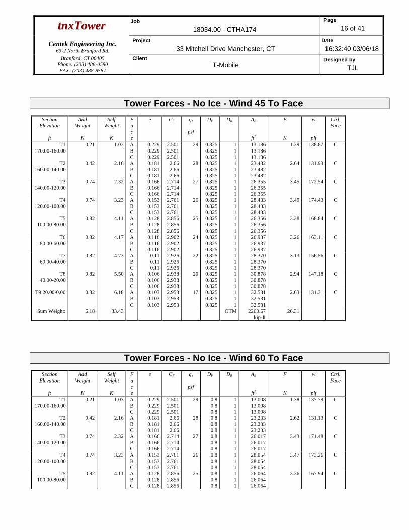
ttnnxxTToowweerr Job18034.00 - CTHA174
Page16 of 41
Centek Engineering Inc.63-2 North Branford Rd.
Project33 Mitchell Drive Manchester, CT
Date16:32:40 03/06/18
Branford, CT 06405Phone: (203) 488-0580FAX: (203) 488-8587
ClientT-Mobile
Designed byTJL
Tower Forces - No Ice - Wind 45 To FaceSection
Elevation
ft
AddWeight
K
SelfWeight
K
Face
e CF qz
psf
DF DR AE
ft2
F
K
w
plf
Ctrl.Face
T1
170.00-160.00
0.21 1.03 A
B
C
0.229
0.229
0.229
2.501
2.501
2.501
29 0.825
0.825
0.825
1
1
1
13.186
13.186
13.186
1.39 138.87 C
T2
160.00-140.00
0.42 2.16 A
B
C
0.181
0.181
0.181
2.66
2.66
2.66
28 0.825
0.825
0.825
1
1
1
23.482
23.482
23.482
2.64 131.93 C
T3
140.00-120.00
0.74 2.32 A
B
C
0.166
0.166
0.166
2.714
2.714
2.714
27 0.825
0.825
0.825
1
1
1
26.355
26.355
26.355
3.45 172.54 C
T4
120.00-100.00
0.74 3.23 A
B
C
0.153
0.153
0.153
2.761
2.761
2.761
26 0.825
0.825
0.825
1
1
1
28.433
28.433
28.433
3.49 174.43 C
T5
100.00-80.00
0.82 4.11 A
B
C
0.128
0.128
0.128
2.856
2.856
2.856
25 0.825
0.825
0.825
1
1
1
26.356
26.356
26.356
3.38 168.84 C
T6
80.00-60.00
0.82 4.17 A
B
C
0.116
0.116
0.116
2.902
2.902
2.902
24 0.825
0.825
0.825
1
1
1
26.937
26.937
26.937
3.26 163.11 C
T7
60.00-40.00
0.82 4.73 A
B
C
0.11
0.11
0.11
2.926
2.926
2.926
22 0.825
0.825
0.825
1
1
1
28.370
28.370
28.370
3.13 156.56 C
T8
40.00-20.00
0.82 5.50 A
B
C
0.106
0.106
0.106
2.938
2.938
2.938
20 0.825
0.825
0.825
1
1
1
30.878
30.878
30.878
2.94 147.18 C
T9 20.00-0.00 0.82 6.18 A
B
C
0.103
0.103
0.103
2.953
2.953
2.953
17 0.825
0.825
0.825
1
1
1
32.531
32.531
32.531
2.63 131.31 C
Sum Weight: 6.18 33.43 OTM 2260.67
kip-ft
26.31
Tower Forces - No Ice - Wind 60 To FaceSection
Elevation
ft
AddWeight
K
SelfWeight
K
Face
e CF qz
psf
DF DR AE
ft2
F
K
w
plf
Ctrl.Face
T1
170.00-160.00
0.21 1.03 A
B
C
0.229
0.229
0.229
2.501
2.501
2.501
29 0.8
0.8
0.8
1
1
1
13.008
13.008
13.008
1.38 137.79 C
T2
160.00-140.00
0.42 2.16 A
B
C
0.181
0.181
0.181
2.66
2.66
2.66
28 0.8
0.8
0.8
1
1
1
23.233
23.233
23.233
2.62 131.13 C
T3
140.00-120.00
0.74 2.32 A
B
C
0.166
0.166
0.166
2.714
2.714
2.714
27 0.8
0.8
0.8
1
1
1
26.017
26.017
26.017
3.43 171.48 C
T4
120.00-100.00
0.74 3.23 A
B
C
0.153
0.153
0.153
2.761
2.761
2.761
26 0.8
0.8
0.8
1
1
1
28.054
28.054
28.054
3.47 173.26 C
T5
100.00-80.00
0.82 4.11 A
B
C
0.128
0.128
0.128
2.856
2.856
2.856
25 0.8
0.8
0.8
1
1
1
26.064
26.064
26.064
3.36 167.94 C

ttnnxxTToowweerr Job18034.00 - CTHA174
Page17 of 41
Centek Engineering Inc.63-2 North Branford Rd.
Project33 Mitchell Drive Manchester, CT
Date16:32:40 03/06/18
Branford, CT 06405Phone: (203) 488-0580FAX: (203) 488-8587
ClientT-Mobile
Designed byTJL
SectionElevation
ft
AddWeight
K
SelfWeight
K
Face
e CF qz
psf
DF DR AE
ft2
F
K
w
plf
Ctrl.Face
T6
80.00-60.00
0.82 4.17 A
B
C
0.116
0.116
0.116
2.902
2.902
2.902
24 0.8
0.8
0.8
1
1
1
26.628
26.628
26.628
3.24 162.19 C
T7
60.00-40.00
0.82 4.73 A
B
C
0.11
0.11
0.11
2.926
2.926
2.926
22 0.8
0.8
0.8
1
1
1
28.043
28.043
28.043
3.11 155.65 C
T8
40.00-20.00
0.82 5.50 A
B
C
0.106
0.106
0.106
2.938
2.938
2.938
20 0.8
0.8
0.8
1
1
1
30.475
30.475
30.475
2.92 146.17 C
T9 20.00-0.00 0.82 6.18 A
B
C
0.103
0.103
0.103
2.953
2.953
2.953
17 0.8
0.8
0.8
1
1
1
32.106
32.106
32.106
2.61 130.38 C
Sum Weight: 6.18 33.43 OTM 2246.53
kip-ft
26.14
Tower Forces - No Ice - Wind 90 To FaceSection
Elevation
ft
AddWeight
K
SelfWeight
K
Face
e CF qz
psf
DF DR AE
ft2
F
K
w
plf
Ctrl.Face
T1
170.00-160.00
0.21 1.03 A
B
C
0.229
0.229
0.229
2.501
2.501
2.501
29 0.85
0.85
0.85
1
1
1
13.364
13.364
13.364
1.40 139.96 C
T2
160.00-140.00
0.42 2.16 A
B
C
0.181
0.181
0.181
2.66
2.66
2.66
28 0.85
0.85
0.85
1
1
1
23.732
23.732
23.732
2.65 132.72 C
T3
140.00-120.00
0.74 2.32 A
B
C
0.166
0.166
0.166
2.714
2.714
2.714
27 0.85
0.85
0.85
1
1
1
26.693
26.693
26.693
3.47 173.61 C
T4
120.00-100.00
0.74 3.23 A
B
C
0.153
0.153
0.153
2.761
2.761
2.761
26 0.85
0.85
0.85
1
1
1
28.812
28.812
28.812
3.51 175.61 C
T5
100.00-80.00
0.82 4.11 A
B
C
0.128
0.128
0.128
2.856
2.856
2.856
25 0.85
0.85
0.85
1
1
1
26.648
26.648
26.648
3.39 169.73 C
T6
80.00-60.00
0.82 4.17 A
B
C
0.116
0.116
0.116
2.902
2.902
2.902
24 0.85
0.85
0.85
1
1
1
27.246
27.246
27.246
3.28 164.02 C
T7
60.00-40.00
0.82 4.73 A
B
C
0.11
0.11
0.11
2.926
2.926
2.926
22 0.85
0.85
0.85
1
1
1
28.697
28.697
28.697
3.15 157.47 C
T8
40.00-20.00
0.82 5.50 A
B
C
0.106
0.106
0.106
2.938
2.938
2.938
20 0.85
0.85
0.85
1
1
1
31.281
31.281
31.281
2.96 148.19 C
T9 20.00-0.00 0.82 6.18 A
B
C
0.103
0.103
0.103
2.953
2.953
2.953
17 0.85
0.85
0.85
1
1
1
32.956
32.956
32.956
2.64 132.24 C
Sum Weight: 6.18 33.43 OTM 2274.81
kip-ft
26.47

ttnnxxTToowweerr Job18034.00 - CTHA174
Page18 of 41
Centek Engineering Inc.63-2 North Branford Rd.
Project33 Mitchell Drive Manchester, CT
Date16:32:40 03/06/18
Branford, CT 06405Phone: (203) 488-0580FAX: (203) 488-8587
ClientT-Mobile
Designed byTJL
Tower Forces - With Ice - Wind Normal To FaceSection
Elevation
ft
AddWeight
K
SelfWeight
K
Face
e CF qz
psf
DF DR AE
ft2
F
K
w
plf
Ctrl.Face
T1
170.00-160.00
1.76 6.81 A
B
C
0.652
0.652
0.652
1.781
1.781
1.781
8 1
1
1
1
1
1
47.163
47.163
47.163
0.69 68.77 C
T2
160.00-140.00
3.49 12.52 A
B
C
0.502
0.502
0.502
1.898
1.898
1.898
7 1
1
1
1
1
1
75.467
75.467
75.467
1.31 65.43 C
T3
140.00-120.00
5.97 13.21 A
B
C
0.443
0.443
0.443
1.985
1.985
1.985
7 1
1
1
1
1
1
77.371
77.371
77.371
1.76 88.21 C
T4
120.00-100.00
5.90 14.45 A
B
C
0.396
0.396
0.396
2.071
2.071
2.071
7 1
1
1
1
1
1
78.585
78.585
78.585
1.81 90.75 C
T5
100.00-80.00
6.29 15.19 A
B
C
0.322
0.322
0.322
2.239
2.239
2.239
7 1
1
1
1
1
1
69.163
69.163
69.163
1.79 89.72 C
T6
80.00-60.00
6.18 15.21 A
B
C
0.29
0.29
0.29
2.324
2.324
2.324
6 1
1
1
1
1
1
68.930
68.930
68.930
1.72 86.21 C
T7
60.00-40.00
6.04 15.81 A
B
C
0.265
0.265
0.265
2.394
2.394
2.394
6 1
1
1
1
1
1
69.360
69.360
69.360
1.63 81.40 C
T8
40.00-20.00
5.84 16.77 A
B
C
0.246
0.246
0.246
2.449
2.449
2.449
5 1
1
1
1
1
1
71.507
71.507
71.507
1.49 74.62 C
T9 20.00-0.00 5.44 16.74 A
B
C
0.224
0.224
0.224
2.516
2.516
2.516
5 1
1
1
1
1
1
70.861
70.861
70.861
1.29 64.30 C
Sum Weight: 46.93 126.72 OTM 1159.96
kip-ft
13.50
Tower Forces - With Ice - Wind 45 To FaceSection
Elevation
ft
AddWeight
K
SelfWeight
K
Face
e CF qz
psf
DF DR AE
ft2
F
K
w
plf
Ctrl.Face
T1
170.00-160.00
1.76 6.81 A
B
C
0.652
0.652
0.652
1.781
1.781
1.781
8 0.825
0.825
0.825
1
1
1
45.918
45.918
45.918
0.67 67.32 C
T2
160.00-140.00
3.49 12.52 A
B
C
0.502
0.502
0.502
1.898
1.898
1.898
7 0.825
0.825
0.825
1
1
1
73.722
73.722
73.722
1.29 64.37 C
T3
140.00-120.00
5.97 13.21 A
B
C
0.443
0.443
0.443
1.985
1.985
1.985
7 0.825
0.825
0.825
1
1
1
75.005
75.005
75.005
1.74 86.76 C
T4
120.00-100.00
5.90 14.45 A
B
C
0.396
0.396
0.396
2.071
2.071
2.071
7 0.825
0.825
0.825
1
1
1
75.934
75.934
75.934
1.78 89.11 C
T5
100.00-80.00
6.29 15.19 A
B
0.322
0.322
2.239
2.239
7 0.825
0.825
1
1
67.120
67.120
1.77 88.41 C

ttnnxxTToowweerr Job18034.00 - CTHA174
Page19 of 41
Centek Engineering Inc.63-2 North Branford Rd.
Project33 Mitchell Drive Manchester, CT
Date16:32:40 03/06/18
Branford, CT 06405Phone: (203) 488-0580FAX: (203) 488-8587
ClientT-Mobile
Designed byTJL
SectionElevation
ft
AddWeight
K
SelfWeight
K
Face
e CF qz
psf
DF DR AE
ft2
F
K
w
plf
Ctrl.Face
C 0.322 2.239 0.825 1 67.120
T6
80.00-60.00
6.18 15.21 A
B
C
0.29
0.29
0.29
2.324
2.324
2.324
6 0.825
0.825
0.825
1
1
1
66.767
66.767
66.767
1.70 84.85 C
T7
60.00-40.00
6.04 15.81 A
B
C
0.265
0.265
0.265
2.394
2.394
2.394
6 0.825
0.825
0.825
1
1
1
67.073
67.073
67.073
1.60 80.01 C
T8
40.00-20.00
5.84 16.77 A
B
C
0.246
0.246
0.246
2.449
2.449
2.449
5 0.825
0.825
0.825
1
1
1
68.687
68.687
68.687
1.46 73.05 C
T9 20.00-0.00 5.44 16.74 A
B
C
0.224
0.224
0.224
2.516
2.516
2.516
5 0.825
0.825
0.825
1
1
1
67.884
67.884
67.884
1.26 62.83 C
Sum Weight: 46.93 126.72 OTM 1140.15
kip-ft
13.26
Tower Forces - With Ice - Wind 60 To FaceSection
Elevation
ft
AddWeight
K
SelfWeight
K
Face
e CF qz
psf
DF DR AE
ft2
F
K
w
plf
Ctrl.Face
T1
170.00-160.00
1.76 6.81 A
B
C
0.652
0.652
0.652
1.781
1.781
1.781
8 0.8
0.8
0.8
1
1
1
45.740
45.740
45.740
0.67 67.12 C
T2
160.00-140.00
3.49 12.52 A
B
C
0.502
0.502
0.502
1.898
1.898
1.898
7 0.8
0.8
0.8
1
1
1
73.472
73.472
73.472
1.28 64.22 C
T3
140.00-120.00
5.97 13.21 A
B
C
0.443
0.443
0.443
1.985
1.985
1.985
7 0.8
0.8
0.8
1
1
1
74.667
74.667
74.667
1.73 86.55 C
T4
120.00-100.00
5.90 14.45 A
B
C
0.396
0.396
0.396
2.071
2.071
2.071
7 0.8
0.8
0.8
1
1
1
75.556
75.556
75.556
1.78 88.87 C
T5
100.00-80.00
6.29 15.19 A
B
C
0.322
0.322
0.322
2.239
2.239
2.239
7 0.8
0.8
0.8
1
1
1
66.829
66.829
66.829
1.76 88.22 C
T6
80.00-60.00
6.18 15.21 A
B
C
0.29
0.29
0.29
2.324
2.324
2.324
6 0.8
0.8
0.8
1
1
1
66.458
66.458
66.458
1.69 84.65 C
T7
60.00-40.00
6.04 15.81 A
B
C
0.265
0.265
0.265
2.394
2.394
2.394
6 0.8
0.8
0.8
1
1
1
66.746
66.746
66.746
1.60 79.82 C
T8
40.00-20.00
5.84 16.77 A
B
C
0.246
0.246
0.246
2.449
2.449
2.449
5 0.8
0.8
0.8
1
1
1
68.284
68.284
68.284
1.46 72.83 C
T9 20.00-0.00 5.44 16.74 A
B
C
0.224
0.224
0.224
2.516
2.516
2.516
5 0.8
0.8
0.8
1
1
1
67.459
67.459
67.459
1.25 62.62 C
Sum Weight: 46.93 126.72 OTM 1137.32
kip-ft
13.23

ttnnxxTToowweerr Job18034.00 - CTHA174
Page20 of 41
Centek Engineering Inc.63-2 North Branford Rd.
Project33 Mitchell Drive Manchester, CT
Date16:32:40 03/06/18
Branford, CT 06405Phone: (203) 488-0580FAX: (203) 488-8587
ClientT-Mobile
Designed byTJL
Tower Forces - With Ice - Wind 90 To FaceSection
Elevation
ft
AddWeight
K
SelfWeight
K
Face
e CF qz
psf
DF DR AE
ft2
F
K
w
plf
Ctrl.Face
T1
170.00-160.00
1.76 6.81 A
B
C
0.652
0.652
0.652
1.781
1.781
1.781
8 0.85
0.85
0.85
1
1
1
46.096
46.096
46.096
0.68 67.53 C
T2
160.00-140.00
3.49 12.52 A
B
C
0.502
0.502
0.502
1.898
1.898
1.898
7 0.85
0.85
0.85
1
1
1
73.971
73.971
73.971
1.29 64.52 C
T3
140.00-120.00
5.97 13.21 A
B
C
0.443
0.443
0.443
1.985
1.985
1.985
7 0.85
0.85
0.85
1
1
1
75.343
75.343
75.343
1.74 86.97 C
T4
120.00-100.00
5.90 14.45 A
B
C
0.396
0.396
0.396
2.071
2.071
2.071
7 0.85
0.85
0.85
1
1
1
76.313
76.313
76.313
1.79 89.34 C
T5
100.00-80.00
6.29 15.19 A
B
C
0.322
0.322
0.322
2.239
2.239
2.239
7 0.85
0.85
0.85
1
1
1
67.412
67.412
67.412
1.77 88.60 C
T6
80.00-60.00
6.18 15.21 A
B
C
0.29
0.29
0.29
2.324
2.324
2.324
6 0.85
0.85
0.85
1
1
1
67.076
67.076
67.076
1.70 85.04 C
T7
60.00-40.00
6.04 15.81 A
B
C
0.265
0.265
0.265
2.394
2.394
2.394
6 0.85
0.85
0.85
1
1
1
67.399
67.399
67.399
1.60 80.21 C
T8
40.00-20.00
5.84 16.77 A
B
C
0.246
0.246
0.246
2.449
2.449
2.449
5 0.85
0.85
0.85
1
1
1
69.090
69.090
69.090
1.47 73.27 C
T9 20.00-0.00 5.44 16.74 A
B
C
0.224
0.224
0.224
2.516
2.516
2.516
5 0.85
0.85
0.85
1
1
1
68.309
68.309
68.309
1.26 63.04 C
Sum Weight: 46.93 126.72 OTM 1142.98
kip-ft
13.30
Tower Forces - Service - Wind Normal To FaceSection
Elevation
ft
AddWeight
K
SelfWeight
K
Face
e CF qz
psf
DF DR AE
ft2
F
K
w
plf
Ctrl.Face
T1
170.00-160.00
0.21 1.03 A
B
C
0.229
0.229
0.229
2.501
2.501
2.501
11 1
1
1
1
1
1
14.431
14.431
14.431
0.56 56.05 C
T2
160.00-140.00
0.42 2.16 A
B
C
0.181
0.181
0.181
2.66
2.66
2.66
11 1
1
1
1
1
1
25.227
25.227
25.227
1.05 52.61 C
T3
140.00-120.00
0.74 2.32 A
B
C
0.166
0.166
0.166
2.714
2.714
2.714
10 1
1
1
1
1
1
28.721
28.721
28.721
1.38 68.88 C
T4
120.00-100.00
0.74 3.23 A
B
C
0.153
0.153
0.153
2.761
2.761
2.761
10 1
1
1
1
1
1
31.083
31.083
31.083
1.40 69.89 C
T5 0.82 4.11 A 0.128 2.856 10 1 1 28.398 1.34 67.00 C

ttnnxxTToowweerr Job18034.00 - CTHA174
Page21 of 41
Centek Engineering Inc.63-2 North Branford Rd.
Project33 Mitchell Drive Manchester, CT
Date16:32:40 03/06/18
Branford, CT 06405Phone: (203) 488-0580FAX: (203) 488-8587
ClientT-Mobile
Designed byTJL
SectionElevation
ft
AddWeight
K
SelfWeight
K
Face
e CF qz
psf
DF DR AE
ft2
F
K
w
plf
Ctrl.Face
100.00-80.00 B
C
0.128
0.128
2.856
2.856
1
1
1
1
28.398
28.398
T6
80.00-60.00
0.82 4.17 A
B
C
0.116
0.116
0.116
2.902
2.902
2.902
9 1
1
1
1
1
1
29.099
29.099
29.099
1.30 64.86 C
T7
60.00-40.00
0.82 4.73 A
B
C
0.11
0.11
0.11
2.926
2.926
2.926
9 1
1
1
1
1
1
30.658
30.658
30.658
1.25 62.34 C
T8
40.00-20.00
0.82 5.50 A
B
C
0.106
0.106
0.106
2.938
2.938
2.938
8 1
1
1
1
1
1
33.698
33.698
33.698
1.18 59.02 C
T9 20.00-0.00 0.82 6.18 A
B
C
0.103
0.103
0.103
2.953
2.953
2.953
7 1
1
1
1
1
1
35.508
35.508
35.508
1.05 52.73 C
Sum Weight: 6.18 33.43 OTM 902.84
kip-ft
10.51
Tower Forces - Service - Wind 45 To FaceSection
Elevation
ft
AddWeight
K
SelfWeight
K
Face
e CF qz
psf
DF DR AE
ft2
F
K
w
plf
Ctrl.Face
T1
170.00-160.00
0.21 1.03 A
B
C
0.229
0.229
0.229
2.501
2.501
2.501
11 0.825
0.825
0.825
1
1
1
13.186
13.186
13.186
0.53 53.13 C
T2
160.00-140.00
0.42 2.16 A
B
C
0.181
0.181
0.181
2.66
2.66
2.66
11 0.825
0.825
0.825
1
1
1
23.482
23.482
23.482
1.01 50.48 C
T3
140.00-120.00
0.74 2.32 A
B
C
0.166
0.166
0.166
2.714
2.714
2.714
10 0.825
0.825
0.825
1
1
1
26.355
26.355
26.355
1.32 66.02 C
T4
120.00-100.00
0.74 3.23 A
B
C
0.153
0.153
0.153
2.761
2.761
2.761
10 0.825
0.825
0.825
1
1
1
28.433
28.433
28.433
1.33 66.74 C
T5
100.00-80.00
0.82 4.11 A
B
C
0.128
0.128
0.128
2.856
2.856
2.856
10 0.825
0.825
0.825
1
1
1
26.356
26.356
26.356
1.29 64.60 C
T6
80.00-60.00
0.82 4.17 A
B
C
0.116
0.116
0.116
2.902
2.902
2.902
9 0.825
0.825
0.825
1
1
1
26.937
26.937
26.937
1.25 62.41 C
T7
60.00-40.00
0.82 4.73 A
B
C
0.11
0.11
0.11
2.926
2.926
2.926
9 0.825
0.825
0.825
1
1
1
28.370
28.370
28.370
1.20 59.90 C
T8
40.00-20.00
0.82 5.50 A
B
C
0.106
0.106
0.106
2.938
2.938
2.938
8 0.825
0.825
0.825
1
1
1
30.878
30.878
30.878
1.13 56.31 C
T9 20.00-0.00 0.82 6.18 A
B
C
0.103
0.103
0.103
2.953
2.953
2.953
7 0.825
0.825
0.825
1
1
1
32.531
32.531
32.531
1.00 50.24 C
Sum Weight: 6.18 33.43 OTM 864.96
kip-ft
10.07

ttnnxxTToowweerr Job18034.00 - CTHA174
Page22 of 41
Centek Engineering Inc.63-2 North Branford Rd.
Project33 Mitchell Drive Manchester, CT
Date16:32:40 03/06/18
Branford, CT 06405Phone: (203) 488-0580FAX: (203) 488-8587
ClientT-Mobile
Designed byTJL
Tower Forces - Service - Wind 60 To FaceSection
Elevation
ft
AddWeight
K
SelfWeight
K
Face
e CF qz
psf
DF DR AE
ft2
F
K
w
plf
Ctrl.Face
T1
170.00-160.00
0.21 1.03 A
B
C
0.229
0.229
0.229
2.501
2.501
2.501
11 0.8
0.8
0.8
1
1
1
13.008
13.008
13.008
0.53 52.72 C
T2
160.00-140.00
0.42 2.16 A
B
C
0.181
0.181
0.181
2.66
2.66
2.66
11 0.8
0.8
0.8
1
1
1
23.233
23.233
23.233
1.00 50.17 C
T3
140.00-120.00
0.74 2.32 A
B
C
0.166
0.166
0.166
2.714
2.714
2.714
10 0.8
0.8
0.8
1
1
1
26.017
26.017
26.017
1.31 65.61 C
T4
120.00-100.00
0.74 3.23 A
B
C
0.153
0.153
0.153
2.761
2.761
2.761
10 0.8
0.8
0.8
1
1
1
28.054
28.054
28.054
1.33 66.29 C
T5
100.00-80.00
0.82 4.11 A
B
C
0.128
0.128
0.128
2.856
2.856
2.856
10 0.8
0.8
0.8
1
1
1
26.064
26.064
26.064
1.29 64.26 C
T6
80.00-60.00
0.82 4.17 A
B
C
0.116
0.116
0.116
2.902
2.902
2.902
9 0.8
0.8
0.8
1
1
1
26.628
26.628
26.628
1.24 62.06 C
T7
60.00-40.00
0.82 4.73 A
B
C
0.11
0.11
0.11
2.926
2.926
2.926
9 0.8
0.8
0.8
1
1
1
28.043
28.043
28.043
1.19 59.55 C
T8
40.00-20.00
0.82 5.50 A
B
C
0.106
0.106
0.106
2.938
2.938
2.938
8 0.8
0.8
0.8
1
1
1
30.475
30.475
30.475
1.12 55.93 C
T9 20.00-0.00 0.82 6.18 A
B
C
0.103
0.103
0.103
2.953
2.953
2.953
7 0.8
0.8
0.8
1
1
1
32.106
32.106
32.106
1.00 49.88 C
Sum Weight: 6.18 33.43 OTM 859.55
kip-ft
10.00
Tower Forces - Service - Wind 90 To FaceSection
Elevation
ft
AddWeight
K
SelfWeight
K
Face
e CF qz
psf
DF DR AE
ft2
F
K
w
plf
Ctrl.Face
T1
170.00-160.00
0.21 1.03 A
B
C
0.229
0.229
0.229
2.501
2.501
2.501
11 0.85
0.85
0.85
1
1
1
13.364
13.364
13.364
0.54 53.55 C
T2
160.00-140.00
0.42 2.16 A
B
C
0.181
0.181
0.181
2.66
2.66
2.66
11 0.85
0.85
0.85
1
1
1
23.732
23.732
23.732
1.02 50.78 C
T3
140.00-120.00
0.74 2.32 A
B
C
0.166
0.166
0.166
2.714
2.714
2.714
10 0.85
0.85
0.85
1
1
1
26.693
26.693
26.693
1.33 66.43 C
T4
120.00-100.00
0.74 3.23 A
B
C
0.153
0.153
0.153
2.761
2.761
2.761
10 0.85
0.85
0.85
1
1
1
28.812
28.812
28.812
1.34 67.19 C
T5 0.82 4.11 A 0.128 2.856 10 0.85 1 26.648 1.30 64.94 C

ttnnxxTToowweerr Job18034.00 - CTHA174
Page23 of 41
Centek Engineering Inc.63-2 North Branford Rd.
Project33 Mitchell Drive Manchester, CT
Date16:32:40 03/06/18
Branford, CT 06405Phone: (203) 488-0580FAX: (203) 488-8587
ClientT-Mobile
Designed byTJL
SectionElevation
ft
AddWeight
K
SelfWeight
K
Face
e CF qz
psf
DF DR AE
ft2
F
K
w
plf
Ctrl.Face
100.00-80.00 B
C
0.128
0.128
2.856
2.856
0.85
0.85
1
1
26.648
26.648
T6
80.00-60.00
0.82 4.17 A
B
C
0.116
0.116
0.116
2.902
2.902
2.902
9 0.85
0.85
0.85
1
1
1
27.246
27.246
27.246
1.26 62.76 C
T7
60.00-40.00
0.82 4.73 A
B
C
0.11
0.11
0.11
2.926
2.926
2.926
9 0.85
0.85
0.85
1
1
1
28.697
28.697
28.697
1.20 60.25 C
T8
40.00-20.00
0.82 5.50 A
B
C
0.106
0.106
0.106
2.938
2.938
2.938
8 0.85
0.85
0.85
1
1
1
31.281
31.281
31.281
1.13 56.70 C
T9 20.00-0.00 0.82 6.18 A
B
C
0.103
0.103
0.103
2.953
2.953
2.953
7 0.85
0.85
0.85
1
1
1
32.956
32.956
32.956
1.01 50.60 C
Sum Weight: 6.18 33.43 OTM 870.37
kip-ft
10.13
Force TotalsLoadCase
VerticalForces
K
Sum ofForces
XK
Sum ofForces
ZK
Sum ofOverturningMoments, Mx
kip-ft
Sum ofOverturningMoments, Mz
kip-ft
Sum of Torques
kip-ftLeg Weight 23.10
Bracing Weight 10.33
Total Member Self-Weight 33.43 2.04 13.26
Total Weight 51.68 2.04 13.26
Wind 0 deg - No Ice -0.19 -38.45 -3923.96 41.54 -6.77
Wind 30 deg - No Ice 19.06 -31.66 -3197.08 -1960.75 -6.04
Wind 45 deg - No Ice 26.57 -25.63 -2584.31 -2724.57 -5.17
Wind 60 deg - No Ice 31.94 -18.44 -1883.91 -3252.81 -3.73
Wind 90 deg - No Ice 36.94 -0.68 -108.18 -3743.85 -0.50
Wind 120 deg - No Ice 33.20 19.39 1989.53 -3372.14 2.85
Wind 135 deg - No Ice 26.62 27.06 2767.10 -2682.31 4.97
Wind 150 deg - No Ice 17.83 32.39 3319.11 -1762.33 5.31
Wind 180 deg - No Ice -0.06 36.88 3774.59 22.14 5.96
Wind 210 deg - No Ice -17.93 32.41 3321.89 1803.97 5.22
Wind 225 deg - No Ice -26.18 26.36 2704.88 2687.26 3.71
Wind 240 deg - No Ice -33.44 19.31 1977.83 3434.96 3.92
Wind 270 deg - No Ice -37.03 -0.67 -106.85 3783.28 1.32
Wind 300 deg - No Ice -31.97 -18.39 -1876.55 3284.35 -2.23
Wind 315 deg - No Ice -27.26 -26.28 -2638.59 2810.51 -3.91
Wind 330 deg - No Ice -19.13 -31.64 -3194.45 1997.72 -5.31
Member Ice 93.29
Total Weight Ice 208.06 1.31 71.43
Wind 0 deg - Ice -0.06 -17.67 -1750.68 80.28 -3.61
Wind 30 deg - Ice 8.83 -14.88 -1462.12 -811.87 -2.74
Wind 45 deg - Ice 12.38 -12.10 -1186.64 -1162.48 -2.04
Wind 60 deg - Ice 14.99 -8.66 -856.76 -1414.60 -1.14
Wind 90 deg - Ice 17.30 -0.21 -32.03 -1637.42 0.75
Wind 120 deg - Ice 15.27 8.89 884.96 -1441.22 2.45
Wind 135 deg - Ice 12.33 12.47 1238.11 -1144.05 3.26
Wind 150 deg - Ice 8.46 15.11 1500.94 -751.81 3.40
Wind 180 deg - Ice -0.01 17.32 1718.07 73.61 3.36

ttnnxxTToowweerr Job18034.00 - CTHA174
Page24 of 41
Centek Engineering Inc.63-2 North Branford Rd.
Project33 Mitchell Drive Manchester, CT
Date16:32:40 03/06/18
Branford, CT 06405Phone: (203) 488-0580FAX: (203) 488-8587
ClientT-Mobile
Designed byTJL
LoadCase
VerticalForces
K
Sum ofForces
XK
Sum ofForces
ZK
Sum ofOverturningMoments, Mx
kip-ft
Sum ofOverturningMoments, Mz
kip-ft
Sum of Torques
kip-ftWind 210 deg - Ice -8.48 15.11 1501.48 898.41 2.48
Wind 225 deg - Ice -12.26 12.32 1224.76 1285.57 1.59
Wind 240 deg - Ice -15.34 8.86 880.76 1594.50 1.16
Wind 270 deg - Ice -17.33 -0.21 -32.50 1783.94 -0.50
Wind 300 deg - Ice -15.00 -8.65 -855.18 1559.09 -2.22
Wind 315 deg - Ice -12.53 -12.23 -1197.55 1317.71 -2.93
Wind 330 deg - Ice -8.85 -14.88 -1461.55 958.37 -3.40
Total Weight 51.68 2.04 13.26
Wind 0 deg - Service -0.07 -14.71 -1500.77 13.45 -2.59
Wind 30 deg - Service 7.29 -12.11 -1222.66 -752.65 -2.31
Wind 45 deg - Service 10.17 -9.81 -988.21 -1044.90 -1.98
Wind 60 deg - Service 12.22 -7.06 -720.22 -1247.01 -1.43
Wind 90 deg - Service 14.13 -0.26 -40.81 -1434.89 -0.19
Wind 120 deg - Service 12.70 7.42 761.80 -1292.67 1.09
Wind 135 deg - Service 10.18 10.35 1059.31 -1028.73 1.90
Wind 150 deg - Service 6.82 12.39 1270.51 -676.74 2.03
Wind 180 deg - Service -0.02 14.11 1444.79 6.03 2.28
Wind 210 deg - Service -6.86 12.40 1271.58 687.78 2.00
Wind 225 deg - Service -10.02 10.09 1035.50 1025.73 1.42
Wind 240 deg - Service -12.80 7.39 757.33 1311.81 1.50
Wind 270 deg - Service -14.17 -0.26 -40.30 1445.08 0.51
Wind 300 deg - Service -12.23 -7.04 -717.41 1254.19 -0.85
Wind 315 deg - Service -10.43 -10.06 -1008.97 1072.89 -1.50
Wind 330 deg - Service -7.32 -12.10 -1221.65 761.91 -2.03
Load CombinationsComb.
No.Description
1 Dead Only
2 1.2 Dead+1.6 Wind 0 deg - No Ice
3 0.9 Dead+1.6 Wind 0 deg - No Ice
4 1.2 Dead+1.6 Wind 30 deg - No Ice
5 0.9 Dead+1.6 Wind 30 deg - No Ice
6 1.2 Dead+1.6 Wind 45 deg - No Ice
7 0.9 Dead+1.6 Wind 45 deg - No Ice
8 1.2 Dead+1.6 Wind 60 deg - No Ice
9 0.9 Dead+1.6 Wind 60 deg - No Ice
10 1.2 Dead+1.6 Wind 90 deg - No Ice
11 0.9 Dead+1.6 Wind 90 deg - No Ice
12 1.2 Dead+1.6 Wind 120 deg - No Ice
13 0.9 Dead+1.6 Wind 120 deg - No Ice
14 1.2 Dead+1.6 Wind 135 deg - No Ice
15 0.9 Dead+1.6 Wind 135 deg - No Ice
16 1.2 Dead+1.6 Wind 150 deg - No Ice
17 0.9 Dead+1.6 Wind 150 deg - No Ice
18 1.2 Dead+1.6 Wind 180 deg - No Ice
19 0.9 Dead+1.6 Wind 180 deg - No Ice
20 1.2 Dead+1.6 Wind 210 deg - No Ice
21 0.9 Dead+1.6 Wind 210 deg - No Ice
22 1.2 Dead+1.6 Wind 225 deg - No Ice
23 0.9 Dead+1.6 Wind 225 deg - No Ice
24 1.2 Dead+1.6 Wind 240 deg - No Ice
25 0.9 Dead+1.6 Wind 240 deg - No Ice
26 1.2 Dead+1.6 Wind 270 deg - No Ice
27 0.9 Dead+1.6 Wind 270 deg - No Ice
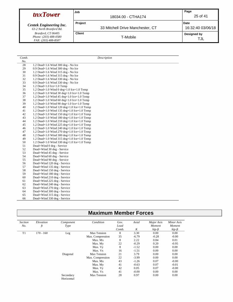
ttnnxxTToowweerr Job18034.00 - CTHA174
Page25 of 41
Centek Engineering Inc.63-2 North Branford Rd.
Project33 Mitchell Drive Manchester, CT
Date16:32:40 03/06/18
Branford, CT 06405Phone: (203) 488-0580FAX: (203) 488-8587
ClientT-Mobile
Designed byTJL
Comb.No.
Description
28 1.2 Dead+1.6 Wind 300 deg - No Ice
29 0.9 Dead+1.6 Wind 300 deg - No Ice
30 1.2 Dead+1.6 Wind 315 deg - No Ice
31 0.9 Dead+1.6 Wind 315 deg - No Ice
32 1.2 Dead+1.6 Wind 330 deg - No Ice
33 0.9 Dead+1.6 Wind 330 deg - No Ice
34 1.2 Dead+1.0 Ice+1.0 Temp
35 1.2 Dead+1.0 Wind 0 deg+1.0 Ice+1.0 Temp
36 1.2 Dead+1.0 Wind 30 deg+1.0 Ice+1.0 Temp
37 1.2 Dead+1.0 Wind 45 deg+1.0 Ice+1.0 Temp
38 1.2 Dead+1.0 Wind 60 deg+1.0 Ice+1.0 Temp
39 1.2 Dead+1.0 Wind 90 deg+1.0 Ice+1.0 Temp
40 1.2 Dead+1.0 Wind 120 deg+1.0 Ice+1.0 Temp
41 1.2 Dead+1.0 Wind 135 deg+1.0 Ice+1.0 Temp
42 1.2 Dead+1.0 Wind 150 deg+1.0 Ice+1.0 Temp
43 1.2 Dead+1.0 Wind 180 deg+1.0 Ice+1.0 Temp
44 1.2 Dead+1.0 Wind 210 deg+1.0 Ice+1.0 Temp
45 1.2 Dead+1.0 Wind 225 deg+1.0 Ice+1.0 Temp
46 1.2 Dead+1.0 Wind 240 deg+1.0 Ice+1.0 Temp
47 1.2 Dead+1.0 Wind 270 deg+1.0 Ice+1.0 Temp
48 1.2 Dead+1.0 Wind 300 deg+1.0 Ice+1.0 Temp
49 1.2 Dead+1.0 Wind 315 deg+1.0 Ice+1.0 Temp
50 1.2 Dead+1.0 Wind 330 deg+1.0 Ice+1.0 Temp
51 Dead+Wind 0 deg - Service
52 Dead+Wind 30 deg - Service
53 Dead+Wind 45 deg - Service
54 Dead+Wind 60 deg - Service
55 Dead+Wind 90 deg - Service
56 Dead+Wind 120 deg - Service
57 Dead+Wind 135 deg - Service
58 Dead+Wind 150 deg - Service
59 Dead+Wind 180 deg - Service
60 Dead+Wind 210 deg - Service
61 Dead+Wind 225 deg - Service
62 Dead+Wind 240 deg - Service
63 Dead+Wind 270 deg - Service
64 Dead+Wind 300 deg - Service
65 Dead+Wind 315 deg - Service
66 Dead+Wind 330 deg - Service
Maximum Member ForcesSection
No.Elevation
ftComponent
TypeCondition Gov.
LoadComb.
Axial
K
Major AxisMoment
kip-ft
Minor AxisMoment
kip-ftT1 170 - 160 Leg Max Tension 8 3.30 0.00 0.00
Max. Compression 35 -6.79 -0.28 -0.00
Max. Mx 8 2.22 0.84 0.01
Max. My 22 -0.29 0.20 -0.95
Max. Vy 8 -1.52 0.00 0.00
Max. Vx 16 -1.51 0.00 0.00
Diagonal Max Tension 21 3.79 0.00 0.00
Max. Compression 22 -3.99 0.00 0.00
Max. Mx 43 -1.26 0.07 -0.00
Max. My 41 -0.63 0.07 -0.01
Max. Vy 42 0.05 0.07 -0.00
Max. Vx 41 -0.00 0.00 0.00
Secondary
Horizontal
Max Tension 28 0.97 0.00 0.00

ttnnxxTToowweerr Job18034.00 - CTHA174
Page26 of 41
Centek Engineering Inc.63-2 North Branford Rd.
Project33 Mitchell Drive Manchester, CT
Date16:32:40 03/06/18
Branford, CT 06405Phone: (203) 488-0580FAX: (203) 488-8587
ClientT-Mobile
Designed byTJL
SectionNo.
Elevationft
ComponentType
Condition Gov.Load
Comb.
Axial
K
Major AxisMoment
kip-ft
Minor AxisMoment
kip-ftMax. Compression 13 -1.03 0.01 0.00
Max. Mx 44 0.09 0.04 0.01
Max. My 36 0.08 0.03 0.02
Max. Vy 44 0.05 0.04 0.01
Max. Vx 45 -0.01 0.00 0.00
Top Girt Max Tension 25 0.76 0.00 0.00
Max. Compression 18 -0.77 0.00 0.00
Max. Mx 34 -0.05 -0.13 0.00
Max. My 41 -0.10 0.00 0.00
Max. Vy 34 0.07 0.00 0.00
Max. Vx 41 -0.00 0.00 0.00
T2 160 - 140 Leg Max Tension 29 25.79 -0.46 0.11
Max. Compression 2 -31.58 1.44 -0.32
Max. Mx 2 -31.58 1.44 -0.32
Max. My 10 -4.34 0.01 1.27
Max. Vy 18 -0.46 -0.46 -0.11
Max. Vx 22 0.66 -0.12 1.10
Diagonal Max Tension 30 5.40 0.00 0.00
Max. Compression 12 -5.54 0.00 0.00
Max. Mx 37 1.16 0.09 -0.01
Max. My 45 -0.41 0.09 0.02
Max. Vy 37 0.06 0.09 -0.01
Max. Vx 45 0.00 0.00 0.00
T3 140 - 120 Leg Max Tension 29 57.91 -1.13 0.07
Max. Compression 24 -71.65 2.90 -0.02
Max. Mx 25 -69.96 2.91 -0.02
Max. My 32 -10.68 0.13 2.60
Max. Vy 8 -2.10 -1.18 0.01
Max. Vx 16 -1.84 0.20 0.23
Diagonal Max Tension 4 8.08 0.00 0.00
Max. Compression 4 -8.09 0.00 0.00
Max. Mx 48 1.85 0.13 -0.02
Max. My 35 0.11 0.12 0.02
Max. Vy 48 0.09 0.13 -0.02
Max. Vx 35 0.01 0.00 0.00
T4 120 - 100 Leg Max Tension 29 92.85 -1.94 -0.01
Max. Compression 24 -111.32 2.81 -0.02
Max. Mx 25 -88.99 2.91 -0.02
Max. My 32 -11.63 0.13 2.60
Max. Vy 8 -0.25 -2.78 0.03
Max. Vx 32 0.26 0.13 2.60
Diagonal Max Tension 4 8.79 0.00 0.00
Max. Compression 4 -8.79 0.00 0.00
Max. Mx 48 1.89 0.19 0.03
Max. My 50 -1.12 0.16 0.03
Max. Vy 48 0.11 0.19 0.03
Max. Vx 50 0.01 0.00 0.00
T5 100 - 80 Leg Max Tension 29 119.86 -2.75 0.04
Max. Compression 24 -142.71 3.42 -0.05
Max. Mx 8 114.95 -3.65 0.05
Max. My 32 -17.27 -0.11 5.21
Max. Vy 18 -1.79 -2.77 -0.07
Max. Vx 10 1.55 0.07 1.36
Diagonal Max Tension 5 14.64 0.00 0.00
Max. Compression 4 -15.16 0.00 0.00
Max. Mx 48 3.40 -0.41 -0.07
Max. My 36 -4.65 -0.38 -0.08
Max. Vy 48 -0.15 -0.41 0.07
Max. Vx 43 0.01 0.00 0.00
T6 80 - 60 Leg Max Tension 29 158.14 -3.58 0.04
Max. Compression 24 -187.85 3.65 -0.03

ttnnxxTToowweerr Job18034.00 - CTHA174
Page27 of 41
Centek Engineering Inc.63-2 North Branford Rd.
Project33 Mitchell Drive Manchester, CT
Date16:32:40 03/06/18
Branford, CT 06405Phone: (203) 488-0580FAX: (203) 488-8587
ClientT-Mobile
Designed byTJL
SectionNo.
Elevationft
ComponentType
Condition Gov.Load
Comb.
Axial
K
Major AxisMoment
kip-ft
Minor AxisMoment
kip-ftMax. Mx 8 153.44 -3.79 0.04
Max. My 32 -19.46 -0.11 5.21
Max. Vy 38 -0.43 -3.13 0.04
Max. Vx 32 0.40 -0.11 5.21
Diagonal Max Tension 4 14.94 0.00 0.00
Max. Compression 4 -15.19 0.00 0.00
Max. Mx 48 3.17 -0.49 0.08
Max. My 35 -0.51 -0.48 -0.08
Max. Vy 48 -0.17 -0.49 0.08
Max. Vx 35 -0.01 0.00 0.00
T7 60 - 40 Leg Max Tension 29 193.76 -3.74 0.03
Max. Compression 24 -228.37 5.84 -0.06
Max. Mx 24 -228.37 5.84 -0.06
Max. My 32 -21.82 -0.06 3.77
Max. Vy 38 0.51 -4.81 0.02
Max. Vx 32 0.37 -0.06 3.77
Diagonal Max Tension 4 14.77 0.00 0.00
Max. Compression 4 -15.31 0.00 0.00
Max. Mx 48 4.07 -0.53 0.08
Max. My 35 3.65 -0.52 -0.08
Max. Vy 48 -0.18 -0.53 0.08
Max. Vx 43 0.01 0.00 0.00
T8 40 - 20 Leg Max Tension 29 228.62 -5.30 0.04
Max. Compression 24 -269.34 3.41 -0.03
Max. Mx 24 -267.77 5.84 -0.06
Max. My 32 -26.71 -0.47 8.34
Max. Vy 38 -0.53 -4.81 0.02
Max. Vx 32 -0.57 -0.47 8.34
Diagonal Max Tension 4 14.90 0.00 0.00
Max. Compression 4 -15.37 0.00 0.00
Max. Mx 48 2.21 -0.78 -0.11
Max. My 43 -4.77 -0.64 0.12
Max. Vy 48 -0.25 -0.78 -0.11
Max. Vx 43 0.02 0.00 0.00
T9 20 - 0 Leg Max Tension 29 259.84 -4.14 0.05
Max. Compression 24 -306.60 0.00 0.00
Max. Mx 8 254.44 -4.29 0.04
Max. My 32 -28.03 -0.47 8.34
Max. Vy 8 -0.51 -4.29 0.04
Max. Vx 32 0.68 -0.47 8.34
Diagonal Max Tension 4 15.44 0.00 0.00
Max. Compression 4 -16.04 0.00 0.00
Max. Mx 47 5.06 -0.75 0.11
Max. My 35 4.19 -0.75 -0.11
Max. Vy 47 -0.24 -0.75 0.11
Max. Vx 35 -0.01 0.00 0.00
Maximum ReactionsLocation Condition Gov.
LoadComb.
VerticalK
Horizontal, XK
Horizontal, ZK
Leg C Max. Vert 24 326.44 32.92 -19.18
Max. Hx 24 326.44 32.92 -19.18
Max. Hz 7 -266.64 -27.69 17.52
Min. Vert 9 -274.91 -29.14 16.99
Min. Hx 9 -274.91 -29.14 16.99

ttnnxxTToowweerr Job18034.00 - CTHA174
Page28 of 41
Centek Engineering Inc.63-2 North Branford Rd.
Project33 Mitchell Drive Manchester, CT
Date16:32:40 03/06/18
Branford, CT 06405Phone: (203) 488-0580FAX: (203) 488-8587
ClientT-Mobile
Designed byTJL
Location Condition Gov.Load
Comb.
VerticalK
Horizontal, XK
Horizontal, ZK
Min. Hz 24 326.44 32.92 -19.18
Leg B Max. Vert 12 323.14 -32.88 -18.86
Max. Hx 29 -275.96 29.27 16.81
Max. Hz 31 -267.58 27.87 17.23
Min. Vert 29 -275.96 29.27 16.81
Min. Hx 12 323.14 -32.88 -18.86
Min. Hz 12 323.14 -32.88 -18.86
Leg A Max. Vert 2 323.66 -0.26 37.91
Max. Hx 27 23.82 4.53 1.81
Max. Hz 2 323.66 -0.26 37.91
Min. Vert 19 -275.63 0.23 -33.75
Min. Hx 10 29.07 -4.52 2.23
Min. Hz 19 -275.63 0.23 -33.75
Tower Mast Reaction SummaryLoad
CombinationVertical
K
Shearx
K
Shearz
K
OverturningMoment, Mx
kip-ft
OverturningMoment, Mz
kip-ft
Torque
kip-ftDead Only 51.68 0.00 0.00 2.04 13.26 0.00
1.2 Dead+1.6 Wind 0 deg - No
Ice
62.02 -0.30 -61.52 -6297.39 61.38 -10.89
0.9 Dead+1.6 Wind 0 deg - No
Ice
46.52 -0.30 -61.52 -6293.41 57.35 -10.87
1.2 Dead+1.6 Wind 30 deg - No
Ice
62.02 30.50 -50.65 -5130.91 -3151.71 -9.69
0.9 Dead+1.6 Wind 30 deg - No
Ice
46.52 30.50 -50.65 -5127.81 -3153.38 -9.68
1.2 Dead+1.6 Wind 45 deg - No
Ice
62.02 42.52 -41.01 -4147.65 -4377.37 -8.29
0.9 Dead+1.6 Wind 45 deg - No
Ice
46.52 42.52 -41.01 -4145.26 -4378.15 -8.28
1.2 Dead+1.6 Wind 60 deg - No
Ice
62.02 51.10 -29.51 -3023.85 -5224.95 -5.99
0.9 Dead+1.6 Wind 60 deg - No
Ice
46.52 51.10 -29.51 -3022.26 -5225.13 -5.99
1.2 Dead+1.6 Wind 90 deg - No
Ice
62.02 59.11 -1.09 -174.55 -6012.83 -0.82
0.9 Dead+1.6 Wind 90 deg - No
Ice
46.52 59.11 -1.09 -175.00 -6012.44 -0.82
1.2 Dead+1.6 Wind 120 deg -
No Ice
62.02 53.12 31.02 3191.70 -5416.38 4.59
0.9 Dead+1.6 Wind 120 deg -
No Ice
46.52 53.12 31.02 3188.76 -5416.43 4.58
1.2 Dead+1.6 Wind 135 deg -
No Ice
62.02 41.50 42.21 4346.37 -4216.34 8.01
0.9 Dead+1.6 Wind 135 deg -
No Ice
46.52 41.50 42.21 4342.59 -4217.27 8.00
1.2 Dead+1.6 Wind 150 deg -
No Ice
62.02 28.53 51.82 5325.22 -2833.08 8.56
0.9 Dead+1.6 Wind 150 deg -
No Ice
46.52 28.53 51.82 5320.72 -2835.04 8.54
1.2 Dead+1.6 Wind 180 deg -
No Ice
62.02 -0.10 59.01 6056.09 30.23 9.59
0.9 Dead+1.6 Wind 180 deg -
No Ice
46.52 -0.10 59.01 6051.06 26.22 9.57
1.2 Dead+1.6 Wind 210 deg - 62.02 -28.69 51.85 5329.67 2889.30 8.39

ttnnxxTToowweerr Job18034.00 - CTHA174
Page29 of 41
Centek Engineering Inc.63-2 North Branford Rd.
Project33 Mitchell Drive Manchester, CT
Date16:32:40 03/06/18
Branford, CT 06405Phone: (203) 488-0580FAX: (203) 488-8587
ClientT-Mobile
Designed byTJL
LoadCombination
Vertical
K
Shearx
K
Shearz
K
OverturningMoment, Mx
kip-ft
OverturningMoment, Mz
kip-ft
Torque
kip-ftNo Ice
0.9 Dead+1.6 Wind 210 deg -
No Ice
46.52 -28.69 51.85 5325.17 2883.24 8.38
1.2 Dead+1.6 Wind 225 deg -
No Ice
62.02 -41.89 42.17 4339.58 4306.76 5.96
0.9 Dead+1.6 Wind 225 deg -
No Ice
46.52 -41.89 42.17 4335.80 4299.64 5.95
1.2 Dead+1.6 Wind 240 deg -
No Ice
62.02 -53.51 30.90 3172.90 5506.59 6.30
0.9 Dead+1.6 Wind 240 deg -
No Ice
46.52 -53.51 30.90 3169.98 5498.59 6.29
1.2 Dead+1.6 Wind 270 deg -
No Ice
62.02 -59.24 -1.07 -172.41 6065.46 2.12
0.9 Dead+1.6 Wind 270 deg -
No Ice
46.52 -59.24 -1.07 -172.86 6057.07 2.12
1.2 Dead+1.6 Wind 300 deg -
No Ice
62.02 -51.15 -29.42 -3012.02 5264.93 -3.59
0.9 Dead+1.6 Wind 300 deg -
No Ice
46.52 -51.15 -29.42 -3010.43 5257.10 -3.59
1.2 Dead+1.6 Wind 315 deg -
No Ice
62.02 -42.53 -40.97 -4141.64 4411.57 -6.31
0.9 Dead+1.6 Wind 315 deg -
No Ice
46.52 -42.53 -40.97 -4139.26 4404.35 -6.29
1.2 Dead+1.6 Wind 330 deg -
No Ice
62.02 -30.61 -50.62 -5126.66 3200.42 -8.56
0.9 Dead+1.6 Wind 330 deg -
No Ice
46.52 -30.61 -50.62 -5123.56 3194.08 -8.54
1.2 Dead+1.0 Ice+1.0 Temp 218.40 0.00 0.00 1.70 74.69 -0.00
1.2 Dead+1.0 Wind 0 deg+1.0
Ice+1.0 Temp
218.40 -0.06 -17.67 -1768.83 83.76 -3.68
1.2 Dead+1.0 Wind 30 deg+1.0
Ice+1.0 Temp
218.40 8.83 -14.88 -1477.24 -817.73 -2.80
1.2 Dead+1.0 Wind 45 deg+1.0
Ice+1.0 Temp
218.40 12.38 -12.10 -1198.72 -1172.19 -2.08
1.2 Dead+1.0 Wind 60 deg+1.0
Ice+1.0 Temp
218.40 14.99 -8.66 -865.45 -1426.91 -1.17
1.2 Dead+1.0 Wind 90 deg+1.0
Ice+1.0 Temp
218.40 17.30 -0.21 -31.92 -1652.08 0.75
1.2 Dead+1.0 Wind 120
deg+1.0 Ice+1.0 Temp
218.40 15.27 8.89 894.70 -1453.84 2.48
1.2 Dead+1.0 Wind 135
deg+1.0 Ice+1.0 Temp
218.40 12.19 12.33 1239.79 -1141.83 3.30
1.2 Dead+1.0 Wind 150
deg+1.0 Ice+1.0 Temp
218.40 8.46 15.11 1517.11 -757.20 3.46
1.2 Dead+1.0 Wind 180
deg+1.0 Ice+1.0 Temp
218.40 -0.01 17.32 1736.55 77.01 3.43
1.2 Dead+1.0 Wind 210
deg+1.0 Ice+1.0 Temp
218.40 -8.48 15.11 1517.61 910.58 2.55
1.2 Dead+1.0 Wind 225
deg+1.0 Ice+1.0 Temp
218.40 -12.26 12.32 1238.00 1301.81 1.65
1.2 Dead+1.0 Wind 240
deg+1.0 Ice+1.0 Temp
218.40 -15.34 8.86 890.42 1613.96 1.20
1.2 Dead+1.0 Wind 270
deg+1.0 Ice+1.0 Temp
218.40 -17.33 -0.21 -32.39 1805.35 -0.51
1.2 Dead+1.0 Wind 300
deg+1.0 Ice+1.0 Temp
218.40 -15.00 -8.65 -863.84 1578.14 -2.25
1.2 Dead+1.0 Wind 315
deg+1.0 Ice+1.0 Temp
218.40 -12.39 -12.09 -1198.01 1322.53 -2.97
1.2 Dead+1.0 Wind 330
deg+1.0 Ice+1.0 Temp
218.40 -8.85 -14.88 -1476.65 971.02 -3.45
Dead+Wind 0 deg - Service 51.68 -0.07 -14.71 -1503.74 24.14 -2.60

ttnnxxTToowweerr Job18034.00 - CTHA174
Page30 of 41
Centek Engineering Inc.63-2 North Branford Rd.
Project33 Mitchell Drive Manchester, CT
Date16:32:40 03/06/18
Branford, CT 06405Phone: (203) 488-0580FAX: (203) 488-8587
ClientT-Mobile
Designed byTJL
LoadCombination
Vertical
K
Shearx
K
Shearz
K
OverturningMoment, Mx
kip-ft
OverturningMoment, Mz
kip-ft
Torque
kip-ftDead+Wind 30 deg - Service 51.68 7.29 -12.11 -1224.91 -743.81 -2.32
Dead+Wind 45 deg - Service 51.68 10.17 -9.81 -989.91 -1036.79 -1.98
Dead+Wind 60 deg - Service 51.68 12.22 -7.06 -721.30 -1239.38 -1.43
Dead+Wind 90 deg - Service 51.68 14.13 -0.26 -40.25 -1427.67 -0.20
Dead+Wind 120 deg - Service 51.68 12.70 7.42 764.33 -1285.14 1.10
Dead+Wind 135 deg - Service 51.68 9.92 10.10 1040.32 -998.31 1.92
Dead+Wind 150 deg - Service 51.68 6.82 12.39 1274.24 -667.69 2.05
Dead+Wind 180 deg - Service 51.68 -0.02 14.11 1448.97 16.70 2.29
Dead+Wind 210 deg - Service 51.68 -6.86 12.40 1275.31 700.07 2.00
Dead+Wind 225 deg - Service 51.68 -10.02 10.09 1038.70 1038.88 1.42
Dead+Wind 240 deg - Service 51.68 -12.80 7.39 759.84 1325.66 1.50
Dead+Wind 270 deg - Service 51.68 -14.17 -0.26 -39.73 1459.21 0.51
Dead+Wind 300 deg - Service 51.68 -12.23 -7.04 -718.47 1267.89 -0.86
Dead+Wind 315 deg - Service 51.68 -10.17 -9.80 -988.48 1063.92 -1.51
Dead+Wind 330 deg - Service 51.68 -7.32 -12.10 -1223.90 774.40 -2.05
Solution Summary
LoadComb.
Sum of Applied Forces Sum of Reactions% ErrorPX
KPYK
PZK
PXK
PYK
PZK
1 0.00 -51.68 0.00 0.00 51.68 0.00 0.000%
2 -0.30 -62.02 -61.52 0.30 62.02 61.52 0.000%
3 -0.30 -46.52 -61.52 0.30 46.52 61.52 0.000%
4 30.50 -62.02 -50.65 -30.50 62.02 50.65 0.000%
5 30.50 -46.52 -50.65 -30.50 46.52 50.65 0.000%
6 42.52 -62.02 -41.01 -42.52 62.02 41.01 0.000%
7 42.52 -46.52 -41.01 -42.52 46.52 41.01 0.000%
8 51.10 -62.02 -29.51 -51.10 62.02 29.51 0.000%
9 51.10 -46.52 -29.51 -51.10 46.52 29.51 0.000%
10 59.11 -62.02 -1.09 -59.11 62.02 1.09 0.000%
11 59.11 -46.52 -1.09 -59.11 46.52 1.09 0.000%
12 53.12 -62.02 31.02 -53.12 62.02 -31.02 0.000%
13 53.12 -46.52 31.02 -53.12 46.52 -31.02 0.000%
14 41.50 -62.02 42.21 -41.50 62.02 -42.21 0.000%
15 41.50 -46.52 42.21 -41.50 46.52 -42.21 0.000%
16 28.53 -62.02 51.82 -28.53 62.02 -51.82 0.000%
17 28.53 -46.52 51.82 -28.53 46.52 -51.82 0.000%
18 -0.10 -62.02 59.01 0.10 62.02 -59.01 0.000%
19 -0.10 -46.52 59.01 0.10 46.52 -59.01 0.000%
20 -28.69 -62.02 51.85 28.69 62.02 -51.85 0.000%
21 -28.69 -46.52 51.85 28.69 46.52 -51.85 0.000%
22 -41.89 -62.02 42.17 41.89 62.02 -42.17 0.000%
23 -41.89 -46.52 42.17 41.89 46.52 -42.17 0.000%
24 -53.51 -62.02 30.90 53.51 62.02 -30.90 0.000%
25 -53.51 -46.52 30.90 53.51 46.52 -30.90 0.000%
26 -59.24 -62.02 -1.07 59.24 62.02 1.07 0.000%
27 -59.24 -46.52 -1.07 59.24 46.52 1.07 0.000%
28 -51.15 -62.02 -29.42 51.15 62.02 29.42 0.000%
29 -51.15 -46.52 -29.42 51.15 46.52 29.42 0.000%
30 -42.53 -62.02 -40.97 42.53 62.02 40.97 0.000%
31 -42.53 -46.52 -40.97 42.53 46.52 40.97 0.000%
32 -30.61 -62.02 -50.62 30.61 62.02 50.62 0.000%
33 -30.61 -46.52 -50.62 30.61 46.52 50.62 0.000%
34 0.00 -218.40 0.00 -0.00 218.40 0.00 0.000%
35 -0.06 -218.40 -17.67 0.06 218.40 17.67 0.000%
36 8.83 -218.40 -14.88 -8.83 218.40 14.88 0.000%
37 12.38 -218.40 -12.10 -12.38 218.40 12.10 0.000%

ttnnxxTToowweerr Job18034.00 - CTHA174
Page31 of 41
Centek Engineering Inc.63-2 North Branford Rd.
Project33 Mitchell Drive Manchester, CT
Date16:32:40 03/06/18
Branford, CT 06405Phone: (203) 488-0580FAX: (203) 488-8587
ClientT-Mobile
Designed byTJL
LoadComb.
Sum of Applied Forces Sum of Reactions% ErrorPX
KPYK
PZK
PXK
PYK
PZK
38 14.99 -218.40 -8.66 -14.99 218.40 8.66 0.000%
39 17.30 -218.40 -0.21 -17.30 218.40 0.21 0.000%
40 15.27 -218.40 8.89 -15.27 218.40 -8.89 0.000%
41 12.19 -218.40 12.33 -12.19 218.40 -12.33 0.000%
42 8.46 -218.40 15.11 -8.46 218.40 -15.11 0.000%
43 -0.01 -218.40 17.32 0.01 218.40 -17.32 0.000%
44 -8.48 -218.40 15.11 8.48 218.40 -15.11 0.000%
45 -12.26 -218.40 12.32 12.26 218.40 -12.32 0.000%
46 -15.34 -218.40 8.86 15.34 218.40 -8.86 0.000%
47 -17.33 -218.40 -0.21 17.33 218.40 0.21 0.000%
48 -15.00 -218.40 -8.65 15.00 218.40 8.65 0.000%
49 -12.39 -218.40 -12.09 12.39 218.40 12.09 0.000%
50 -8.85 -218.40 -14.88 8.85 218.40 14.88 0.000%
51 -0.07 -51.68 -14.71 0.07 51.68 14.71 0.000%
52 7.29 -51.68 -12.11 -7.29 51.68 12.11 0.000%
53 10.17 -51.68 -9.81 -10.17 51.68 9.81 0.000%
54 12.22 -51.68 -7.06 -12.22 51.68 7.06 0.000%
55 14.13 -51.68 -0.26 -14.13 51.68 0.26 0.000%
56 12.70 -51.68 7.42 -12.70 51.68 -7.42 0.000%
57 9.92 -51.68 10.09 -9.92 51.68 -10.10 0.000%
58 6.82 -51.68 12.39 -6.82 51.68 -12.39 0.000%
59 -0.02 -51.68 14.11 0.02 51.68 -14.11 0.000%
60 -6.86 -51.68 12.40 6.86 51.68 -12.40 0.000%
61 -10.02 -51.68 10.09 10.02 51.68 -10.09 0.000%
62 -12.80 -51.68 7.39 12.80 51.68 -7.39 0.000%
63 -14.17 -51.68 -0.26 14.17 51.68 0.26 0.000%
64 -12.23 -51.68 -7.04 12.23 51.68 7.04 0.000%
65 -10.17 -51.68 -9.80 10.17 51.68 9.80 0.000%
66 -7.32 -51.68 -12.10 7.32 51.68 12.10 0.000%
Non-Linear Convergence ResultsLoad
CombinationConverged? Number
of CyclesDisplacement
ToleranceForce
Tolerance1 Yes 4 0.00000001 0.00000001
2 Yes 4 0.00000001 0.00000001
3 Yes 4 0.00000001 0.00000001
4 Yes 4 0.00000001 0.00000001
5 Yes 4 0.00000001 0.00000001
6 Yes 4 0.00000001 0.00000001
7 Yes 4 0.00000001 0.00000001
8 Yes 4 0.00000001 0.00000001
9 Yes 4 0.00000001 0.00000001
10 Yes 4 0.00000001 0.00000001
11 Yes 4 0.00000001 0.00000001
12 Yes 4 0.00000001 0.00000001
13 Yes 4 0.00000001 0.00000001
14 Yes 4 0.00000001 0.00000001
15 Yes 4 0.00000001 0.00000001
16 Yes 4 0.00000001 0.00000001
17 Yes 4 0.00000001 0.00000001
18 Yes 4 0.00000001 0.00000001
19 Yes 4 0.00000001 0.00000001
20 Yes 4 0.00000001 0.00000001
21 Yes 4 0.00000001 0.00000001
22 Yes 4 0.00000001 0.00000001

ttnnxxTToowweerr Job18034.00 - CTHA174
Page32 of 41
Centek Engineering Inc.63-2 North Branford Rd.
Project33 Mitchell Drive Manchester, CT
Date16:32:40 03/06/18
Branford, CT 06405Phone: (203) 488-0580FAX: (203) 488-8587
ClientT-Mobile
Designed byTJL
23 Yes 4 0.00000001 0.00000001
24 Yes 4 0.00000001 0.00000001
25 Yes 4 0.00000001 0.00000001
26 Yes 4 0.00000001 0.00000001
27 Yes 4 0.00000001 0.00000001
28 Yes 4 0.00000001 0.00000001
29 Yes 4 0.00000001 0.00000001
30 Yes 4 0.00000001 0.00000001
31 Yes 4 0.00000001 0.00000001
32 Yes 4 0.00000001 0.00000001
33 Yes 4 0.00000001 0.00000001
34 Yes 4 0.00000001 0.00000001
35 Yes 4 0.00000001 0.00000001
36 Yes 4 0.00000001 0.00000001
37 Yes 4 0.00000001 0.00000001
38 Yes 4 0.00000001 0.00000001
39 Yes 4 0.00000001 0.00000001
40 Yes 4 0.00000001 0.00000001
41 Yes 4 0.00000001 0.00000001
42 Yes 4 0.00000001 0.00000001
43 Yes 4 0.00000001 0.00000001
44 Yes 4 0.00000001 0.00000001
45 Yes 4 0.00000001 0.00000001
46 Yes 4 0.00000001 0.00000001
47 Yes 4 0.00000001 0.00000001
48 Yes 4 0.00000001 0.00000001
49 Yes 4 0.00000001 0.00000001
50 Yes 4 0.00000001 0.00000001
51 Yes 4 0.00000001 0.00000001
52 Yes 4 0.00000001 0.00000001
53 Yes 4 0.00000001 0.00000001
54 Yes 4 0.00000001 0.00000001
55 Yes 4 0.00000001 0.00000001
56 Yes 4 0.00000001 0.00000001
57 Yes 4 0.00000001 0.00000001
58 Yes 4 0.00000001 0.00000001
59 Yes 4 0.00000001 0.00000001
60 Yes 4 0.00000001 0.00000001
61 Yes 4 0.00000001 0.00000001
62 Yes 4 0.00000001 0.00000001
63 Yes 4 0.00000001 0.00000001
64 Yes 4 0.00000001 0.00000001
65 Yes 4 0.00000001 0.00000001
66 Yes 4 0.00000001 0.00000001
Maximum Tower Deflections - Service WindSection
No.Elevation
ft
Horz.Deflection
in
Gov.Load
Comb.
Tilt
°
Twist
°T1 170 - 160 2.460 62 0.1139 0.0051
T2 160 - 140 2.214 62 0.1133 0.0045
T3 140 - 120 1.727 62 0.1071 0.0043
T4 120 - 100 1.276 62 0.0925 0.0030
T5 100 - 80 0.900 62 0.0767 0.0023
T6 80 - 60 0.578 62 0.0619 0.0017
T7 60 - 40 0.330 62 0.0447 0.0011
T8 40 - 20 0.149 62 0.0298 0.0006
T9 20 - 0 0.038 62 0.0134 0.0003

ttnnxxTToowweerr Job18034.00 - CTHA174
Page33 of 41
Centek Engineering Inc.63-2 North Branford Rd.
Project33 Mitchell Drive Manchester, CT
Date16:32:40 03/06/18
Branford, CT 06405Phone: (203) 488-0580FAX: (203) 488-8587
ClientT-Mobile
Designed byTJL
SectionNo.
Elevation
ft
Horz.Deflection
in
Gov.Load
Comb.
Tilt
°
Twist
°
Critical Deflections and Radius of Curvature - Service WindElevation
ft
Appurtenance Gov.Load
Comb.
Deflection
in
Tilt
°
Twist
°
Radius ofCurvature
ft170.00 15' Lighting Rod 62 2.460 0.1139 0.0051 Inf
165.00 6-ft Dish 62 2.337 0.1137 0.0048 Inf
160.00 6812 62 2.214 0.1133 0.0045 781335
155.00 6812 62 2.091 0.1125 0.0044 461609
150.00 4-ft Dish 62 1.968 0.1113 0.0044 298848
140.00 SC2-W100AB 62 1.727 0.1071 0.0043 156425
100.00 (4) SBNHH-1D65B 62 0.900 0.0767 0.0023 119967
Maximum Tower Deflections - Design WindSection
No.Elevation
ft
Horz.Deflection
in
Gov.Load
Comb.
Tilt
°
Twist
°T1 170 - 160 10.223 24 0.4733 0.0214
T2 160 - 140 9.201 24 0.4708 0.0189
T3 140 - 120 7.182 24 0.4443 0.0181
T4 120 - 100 5.309 24 0.3842 0.0126
T5 100 - 80 3.746 24 0.3185 0.0096
T6 80 - 60 2.406 24 0.2572 0.0070
T7 60 - 40 1.373 24 0.1855 0.0047
T8 40 - 20 0.621 24 0.1237 0.0025
T9 20 - 0 0.159 24 0.0559 0.0012
Critical Deflections and Radius of Curvature - Design WindElevation
ft
Appurtenance Gov.Load
Comb.
Deflection
in
Tilt
°
Twist
°
Radius ofCurvature
ft170.00 15' Lighting Rod 24 10.223 0.4733 0.0214 425136
165.00 6-ft Dish 24 9.712 0.4725 0.0200 425136
160.00 6812 24 9.201 0.4708 0.0189 200421
155.00 6812 24 8.691 0.4674 0.0184 113546
150.00 4-ft Dish 24 8.183 0.4620 0.0183 72146
140.00 SC2-W100AB 24 7.182 0.4443 0.0181 37394
100.00 (4) SBNHH-1D65B 24 3.746 0.3185 0.0096 28886
Bolt Design Data

ttnnxxTToowweerr Job18034.00 - CTHA174
Page34 of 41
Centek Engineering Inc.63-2 North Branford Rd.
Project33 Mitchell Drive Manchester, CT
Date16:32:40 03/06/18
Branford, CT 06405Phone: (203) 488-0580FAX: (203) 488-8587
ClientT-Mobile
Designed byTJL
SectionNo.
Elevation
ft
ComponentType
BoltGrade
Bolt Size
in
NumberOf
Bolts
MaximumLoad per
BoltK
AllowableLoad
K
RatioLoad
Allowable
AllowableRatio
Criteria
T1 170 Leg A325N 1.0000 6 0.44 53.010.008
1 Bolt Tension
Diagonal A325N 1.0000 1 3.79 12.720.298
1 Member Bearing
Top Girt A325N 1.0000 1 0.76 12.720.060
1 Member Bearing
T2 160 Leg A325N 1.0000 6 4.29 53.010.081
1 Bolt Tension
Diagonal A325N 1.0000 1 5.40 12.720.424
1 Member Bearing
T3 140 Leg A325N 1.0000 6 9.65 53.010.182
1 Bolt Tension
Diagonal A325N 1.0000 1 8.08 12.720.635
1 Member Bearing
T4 120 Leg A325N 1.0000 6 15.47 53.010.292
1 Bolt Tension
Diagonal A325N 1.0000 1 8.79 21.210.415
1 Member Bearing
T5 100 Leg A325N 1.0000 12 9.99 53.010.188
1 Bolt Tension
Diagonal A325N 0.8750 1 14.64 22.180.660
1 Member Bearing
T6 80 Leg A325N 1.0000 12 13.18 53.010.249
1 Bolt Tension
Diagonal A325N 0.8750 1 14.94 22.180.673
1 Member Bearing
T7 60 Leg A325N 1.0000 12 16.15 53.010.305
1 Bolt Tension
Diagonal A325N 0.8750 1 14.77 22.180.666
1 Member Bearing
T8 40 Leg A325N 1.0000 12 19.05 53.010.359
1 Bolt Tension
Diagonal A325N 0.8750 1 14.90 29.580.504
1 Member Bearing
T9 20 Leg F1554-10
5
1.0000 12 21.65 55.220.392
1 Bolt Tension
Diagonal A325N 0.8750 1 15.44 29.580.522
1 Member Bearing
Compression Checks
Leg Design Data (Compression)Section
No.Elevation
ft
Size L
ft
Lu
ft
Kl/r A
in2
Pu
K
fPn
K
RatioPu
fPn
T1 170 - 160 #12ZG - 1.25'' - 1.00'' conn.
(Pirod 207628)
10.02 5.34 45.0
K=1.00
3.6816 -6.63 142.87 0.046
T2 160 - 140 #12ZG - 1.50'' - 1.00'' conn.
(Pirod 207629)
20.03 10.02 37.5
K=1.00
5.3014 -31.58 215.25 0.147
T3 140 - 120 #12ZG - 1.50'' - 1.00'' conn.
(Pirod 207629)
20.03 10.02 37.5
K=1.00
5.3014 -71.65 215.25 0.333
T4 120 - 100 #12ZG - 1.75'' - 1.00'' conn.
(Pirod 195557)
20.03 10.02 31.9
K=1.00
7.2158 -111.32 301.49 0.369
T5 100 - 80 #12ZG -2.00'' - 0.875''
conn.-Trans (Pirod 211843)
20.03 20.03 48.8
K=1.00
9.4248 -142.71 356.29 0.401
T6 80 - 60 #12ZG - 2.00'' - 0.875'' conn.
(Pirod 208333)
20.03 20.03 48.8
K=1.00
9.4248 -187.85 356.29 0.527
T7 60 - 40 #12ZG -2.25'' - 0.875'' conn.
(Pirod 208334)
20.03 20.03 48.8
K=1.00
11.9282 -228.37 451.15 0.506
T8 40 - 20 #12ZG -2.25'' - 0.875'' conn. 20.03 20.03 48.8 11.9282 -267.77 451.15 0.594

ttnnxxTToowweerr Job18034.00 - CTHA174
Page35 of 41
Centek Engineering Inc.63-2 North Branford Rd.
Project33 Mitchell Drive Manchester, CT
Date16:32:40 03/06/18
Branford, CT 06405Phone: (203) 488-0580FAX: (203) 488-8587
ClientT-Mobile
Designed byTJL
SectionNo.
Elevation
ft
Size L
ft
Lu
ft
Kl/r A
in2
Pu
K
fPn
K
RatioPu
fPn
(Pirod 208334) K=1.00
T9 20 - 0 #12ZG - 2.50'' - 0.875'' conn.
(Pirod 208335)
20.03 20.03 48.7
K=1.00
14.7262 -304.81 557.27 0.547
Leg Bending Design Data (Compression)Section
No.Elevation
ft
Size Mux
kip-ft
fMnx
kip-ft
RatioMux
fMnx
Muy
kip-ft
fMny
kip-ft
RatioMuy
fMny
T1 170 - 160 #12ZG - 1.25'' - 1.00'' conn.
(Pirod 207628)
-0.32 41.41 0.008 -0.06 47.82 0.000
T2 160 - 140 #12ZG - 1.50'' - 1.00'' conn.
(Pirod 207629)
1.44 62.50 0.023 -0.32 72.17 0.004
T3 140 - 120 #12ZG - 1.50'' - 1.00'' conn.
(Pirod 207629)
2.90 62.50 0.046 -0.02 72.17 0.000
T4 120 - 100 #12ZG - 1.75'' - 1.00'' conn.
(Pirod 195557)
2.81 87.73 0.032 -0.02 101.30 0.000
T5 100 - 80 #12ZG -2.00'' - 0.875''
conn.-Trans (Pirod 211843)
3.42 103.92 0.033 -0.05 120.00 0.000
T6 80 - 60 #12ZG - 2.00'' - 0.875'' conn.
(Pirod 208333)
3.65 103.92 0.035 -0.03 120.00 0.000
T7 60 - 40 #12ZG -2.25'' - 0.875'' conn.
(Pirod 208334)
5.84 131.95 0.044 -0.06 152.37 0.000
T8 40 - 20 #12ZG -2.25'' - 0.875'' conn.
(Pirod 208334)
5.84 131.95 0.044 -0.06 152.37 0.000
T9 20 - 0 #12ZG - 2.50'' - 0.875'' conn.
(Pirod 208335)
3.41 163.49 0.021 -0.03 188.78 0.000
Leg Interaction Design Data (Compression)Section
No.Elevation
ft
Size RatioPu
fPn
RatioMux
fMnx
RatioMuy
fMny
Comb.StressRatio
Allow.StressRatio
Criteria
T1 170 - 160 #12ZG - 1.25'' - 1.00'' conn.
(Pirod 207628)
0.046 0.008 0.000 0.054 1.0004.8.1
T2 160 - 140 #12ZG - 1.50'' - 1.00'' conn.
(Pirod 207629)
0.147 0.023 0.004 0.174 1.0004.8.1
T3 140 - 120 #12ZG - 1.50'' - 1.00'' conn.
(Pirod 207629)
0.333 0.046 0.000 0.380 1.0004.8.1
T4 120 - 100 #12ZG - 1.75'' - 1.00'' conn.
(Pirod 195557)
0.369 0.032 0.000 0.401 1.0004.8.1
T5 100 - 80 #12ZG -2.00'' - 0.875''
conn.-Trans (Pirod 211843)
0.401 0.033 0.000 0.434 1.0004.8.1
T6 80 - 60 #12ZG - 2.00'' - 0.875'' conn.
(Pirod 208333)
0.527 0.035 0.000 0.563 1.0004.8.1
T7 60 - 40 #12ZG -2.25'' - 0.875'' conn.
(Pirod 208334)
0.506 0.044 0.000 0.551 1.0004.8.1
T8 40 - 20 #12ZG -2.25'' - 0.875'' conn.
(Pirod 208334)
0.594 0.044 0.000 0.638 1.0004.8.1

ttnnxxTToowweerr Job18034.00 - CTHA174
Page36 of 41
Centek Engineering Inc.63-2 North Branford Rd.
Project33 Mitchell Drive Manchester, CT
Date16:32:40 03/06/18
Branford, CT 06405Phone: (203) 488-0580FAX: (203) 488-8587
ClientT-Mobile
Designed byTJL
SectionNo.
Elevation
ft
Size RatioPu
fPn
RatioMux
fMnx
RatioMuy
fMny
Comb.StressRatio
Allow.StressRatio
Criteria
T9 20 - 0 #12ZG - 2.50'' - 0.875'' conn.
(Pirod 208335)
0.547 0.021 0.000 0.568 1.0004.8.1
Truss-Leg Diagonal DataSection
No.Elevation
ftDiagonal Size Ld
ftKl/r fPn
KAin2
VuK
fVn
KStressRatio
T1 170 - 160 0.5 1.48 120.4 165.67 0.1963 1.56 3.44 0.454
T2 160 - 140 0.5 1.46 119.3 238.57 0.1963 0.30 3.50 0.086
T3 140 - 120 0.5 1.46 119.3 238.57 0.1963 2.10 3.50 0.599
T4 120 - 100 0.5 1.44 117.6 324.71 0.1963 0.30 3.62 0.082
T5 100 - 80 0.5 1.39 113.2 424.12 0.1963 1.79 3.76 0.477
T6 80 - 60 0.5 1.39 113.2 424.12 0.1963 0.43 3.76 0.113
T7 60 - 40 0.5 1.38 112.2 536.77 0.1963 0.51 3.80 0.134
T8 40 - 20 0.5 1.38 112.2 536.77 0.1963 0.58 3.80 0.152
T9 20 - 0 0.5 1.36 111.2 662.68 0.1963 0.70 3.85 0.183
Diagonal Design Data (Compression)Section
No.Elevation
ft
Size L
ft
Lu
ft
Kl/r A
in2
Pu
K
fPn
K
RatioPu
fPn
T1 170 - 160 L2 1/2x2 1/2x3/16 12.50 5.67 137.4
K=1.00
0.9020 -3.99 10.79 0.370 1
T2 160 - 140 L2 1/2x2 1/2x3/16 13.80 6.37 154.4
K=1.00
0.9020 -5.54 8.55 0.6481
T3 140 - 120 L3x3x3/16 15.24 7.12 143.4
K=1.00
1.0900 -8.09 11.97 0.6761
T4 120 - 100 L3x3x5/16 16.80 7.92 161.4
K=1.00
1.7800 -8.79 15.43 0.5701
T5 100 - 80 2L3x3x3/16 25.01 12.35 157.9
K=1.00
2.1800 -15.16 19.76 0.7671
T6 80 - 60 2L3x3x3/16 26.26 12.98 165.8
K=1.00
2.1800 -15.19 17.91 0.848 1
T7 60 - 40 2L3x3x3/16 27.59 13.65 174.4
K=1.00
2.1800 -15.31 16.20 0.945 1
T8 40 - 20 2L3 1/2x3 1/2x1/4 29.01 14.35 158.0
K=1.00
3.3800 -15.37 30.59 0.503 1

ttnnxxTToowweerr Job18034.00 - CTHA174
Page37 of 41
Centek Engineering Inc.63-2 North Branford Rd.
Project33 Mitchell Drive Manchester, CT
Date16:32:40 03/06/18
Branford, CT 06405Phone: (203) 488-0580FAX: (203) 488-8587
ClientT-Mobile
Designed byTJL
SectionNo.
Elevation
ft
Size L
ft
Lu
ft
Kl/r A
in2
Pu
K
fPn
K
RatioPu
fPn
T9 20 - 0 2L3 1/2x3 1/2x1/4 30.49 15.09 166.1
K=1.00
3.3800 -16.04 27.66 0.580 1
1 P u / fPn controls
Secondary Horizontal Design Data (Compression)Section
No.Elevation
ft
Size L
ft
Lu
ft
Kl/r A
in2
Pu
K
fPn
K
RatioPu
fPn
T1 170 - 160 L2 1/2x2 1/2x3/16 7.47 6.47 109.9
K=1.10
0.9020 -1.03 15.48 0.066 1
1 P u / fPn controls
Top Girt Design Data (Compression)Section
No.Elevation
ft
Size L
ft
Lu
ft
Kl/r A
in2
Pu
K
fPn
K
RatioPu
fPn
T1 170 - 160 L2 1/2x2 1/2x3/16 7.00 5.67 137.4
K=1.00
0.9020 -0.77 10.80 0.0711
1 P u / fPn controls
Tension Checks
Leg Design Data (Tension)Section
No.Elevation
ft
Size L
ft
Lu
ft
Kl/r A
in2
Pu
K
fPn
K
RatioPu
fPn
T1 170 - 160 #12ZG - 1.25'' - 1.00'' conn.
(Pirod 207628)
10.02 5.34 45.0 3.6816 2.58 165.67 0.016
T2 160 - 140 #12ZG - 1.50'' - 1.00'' conn.
(Pirod 207629)
20.03 10.02 37.5 5.3014 25.62 238.57 0.107
T3 140 - 120 #12ZG - 1.50'' - 1.00'' conn.
(Pirod 207629)
20.03 10.02 37.5 5.3014 57.81 238.57 0.242
T4 120 - 100 #12ZG - 1.75'' - 1.00'' conn.
(Pirod 195557)
20.03 10.02 31.9 7.2158 92.72 324.71 0.286
T5 100 - 80 #12ZG -2.00'' - 0.875''
conn.-Trans (Pirod 211843)
20.03 20.03 48.8 9.4248 118.15 424.12 0.279
T6 80 - 60 #12ZG - 2.00'' - 0.875'' conn. 20.03 20.03 48.8 9.4248 158.14 424.12 0.373

ttnnxxTToowweerr Job18034.00 - CTHA174
Page38 of 41
Centek Engineering Inc.63-2 North Branford Rd.
Project33 Mitchell Drive Manchester, CT
Date16:32:40 03/06/18
Branford, CT 06405Phone: (203) 488-0580FAX: (203) 488-8587
ClientT-Mobile
Designed byTJL
SectionNo.
Elevation
ft
Size L
ft
Lu
ft
Kl/r A
in2
Pu
K
fPn
K
RatioPu
fPn
(Pirod 208333)
T7 60 - 40 #12ZG -2.25'' - 0.875'' conn.
(Pirod 208334)
20.03 20.03 48.8 11.9282 192.83 536.77 0.359
T8 40 - 20 #12ZG -2.25'' - 0.875'' conn.
(Pirod 208334)
20.03 20.03 48.8 11.9282 228.62 536.77 0.426
T9 20 - 0 #12ZG - 2.50'' - 0.875'' conn.
(Pirod 208335)
20.03 20.03 48.7 14.7262 259.84 662.68 0.392
Leg Bending Design Data (Tension)Section
No.Elevation
ft
Size Mux
kip-ft
fMnx
kip-ft
RatioMux
fMnx
Muy
kip-ft
fMny
kip-ft
RatioMuy
fMny
T1 170 - 160 #12ZG - 1.25'' - 1.00'' conn.
(Pirod 207628)
0.81 48.02 0.017 -0.01 55.45 0.000
T2 160 - 140 #12ZG - 1.50'' - 1.00'' conn.
(Pirod 207629)
-1.25 69.27 0.018 -0.26 79.99 0.003
T3 140 - 120 #12ZG - 1.50'' - 1.00'' conn.
(Pirod 207629)
-2.78 69.27 0.040 0.03 79.99 0.000
T4 120 - 100 #12ZG - 1.75'' - 1.00'' conn.
(Pirod 195557)
-2.75 94.48 0.029 0.04 109.10 0.000
T5 100 - 80 #12ZG -2.00'' - 0.875''
conn.-Trans (Pirod 211843)
-3.58 123.71 0.029 0.04 142.84 0.000
T6 80 - 60 #12ZG - 2.00'' - 0.875'' conn.
(Pirod 208333)
-3.58 123.71 0.029 0.04 142.84 0.000
T7 60 - 40 #12ZG -2.25'' - 0.875'' conn.
(Pirod 208334)
-5.30 157.00 0.034 0.04 181.28 0.000
T8 40 - 20 #12ZG -2.25'' - 0.875'' conn.
(Pirod 208334)
-5.30 157.00 0.034 0.04 181.28 0.000
T9 20 - 0 #12ZG - 2.50'' - 0.875'' conn.
(Pirod 208335)
-4.14 194.41 0.021 0.05 224.49 0.000
Leg Interaction Design Data (Tension)Section
No.Elevation
ft
Size RatioPu
fPn
RatioMux
fMnx
RatioMuy
fMny
Comb.StressRatio
Allow.StressRatio
Criteria
T1 170 - 160 #12ZG - 1.25'' - 1.00'' conn.
(Pirod 207628)
0.016 0.017 0.000 0.033 1.0004.8.1
T2 160 - 140 #12ZG - 1.50'' - 1.00'' conn.
(Pirod 207629)
0.107 0.018 0.003 0.129 1.0004.8.1
T3 140 - 120 #12ZG - 1.50'' - 1.00'' conn.
(Pirod 207629)
0.242 0.040 0.000 0.283 1.0004.8.1
T4 120 - 100 #12ZG - 1.75'' - 1.00'' conn.
(Pirod 195557)
0.286 0.029 0.000 0.315 1.0004.8.1
T5 100 - 80 #12ZG -2.00'' - 0.875''
conn.-Trans (Pirod 211843)
0.279 0.029 0.000 0.308 1.0004.8.1
T6 80 - 60 #12ZG - 2.00'' - 0.875'' conn.
(Pirod 208333)
0.373 0.029 0.000 0.402 1.0004.8.1
T7 60 - 40 #12ZG -2.25'' - 0.875'' conn. 0.359 0.034 0.000 0.393 1.0004.8.1

ttnnxxTToowweerr Job18034.00 - CTHA174
Page39 of 41
Centek Engineering Inc.63-2 North Branford Rd.
Project33 Mitchell Drive Manchester, CT
Date16:32:40 03/06/18
Branford, CT 06405Phone: (203) 488-0580FAX: (203) 488-8587
ClientT-Mobile
Designed byTJL
SectionNo.
Elevation
ft
Size RatioPu
fPn
RatioMux
fMnx
RatioMuy
fMny
Comb.StressRatio
Allow.StressRatio
Criteria
(Pirod 208334)
T8 40 - 20 #12ZG -2.25'' - 0.875'' conn.
(Pirod 208334)
0.426 0.034 0.000 0.460 1.0004.8.1
T9 20 - 0 #12ZG - 2.50'' - 0.875'' conn.
(Pirod 208335)
0.392 0.021 0.000 0.414 1.0004.8.1
Truss-Leg Diagonal DataSection
No.Elevation
ftDiagonal Size Ld
ftKl/r fPn
KAin2
Vu
KfVn
KStressRatio
T1 170 - 160 0.5 1.48 120.4 165.67 0.1963 1.56 3.44 0.454
T2 160 - 140 0.5 1.46 119.3 238.57 0.1963 0.30 3.50 0.086
T3 140 - 120 0.5 1.46 119.3 238.57 0.1963 2.10 3.50 0.599
T4 120 - 100 0.5 1.44 117.6 324.71 0.1963 0.30 3.62 0.082
T5 100 - 80 0.5 1.39 113.2 424.12 0.1963 1.79 3.76 0.477
T6 80 - 60 0.5 1.39 113.2 424.12 0.1963 0.43 3.76 0.113
T7 60 - 40 0.5 1.38 112.2 536.77 0.1963 0.51 3.80 0.134
T8 40 - 20 0.5 1.38 112.2 536.77 0.1963 0.58 3.80 0.152
T9 20 - 0 0.5 1.36 111.2 662.68 0.1963 0.70 3.85 0.183
Diagonal Design Data (Tension)Section
No.Elevation
ft
Size L
ft
Lu
ft
Kl/r A
in2
Pu
K
fPn
K
RatioPu
fPn
T1 170 - 160 L2 1/2x2 1/2x3/16 12.50 5.67 90.0 0.9020 3.79 29.22 0.1301
T2 160 - 140 L2 1/2x2 1/2x3/16 13.80 6.37 100.8 0.9020 5.40 29.22 0.1851
T3 140 - 120 L3x3x3/16 15.24 7.12 93.2 1.0900 8.08 35.32 0.2291
T4 120 - 100 L3x3x5/16 16.80 7.92 105.3 1.7800 8.79 57.67 0.1521
T5 100 - 80 2L3x3x3/16 25.01 12.35 159.8 2.1800 14.64 70.63 0.207 1
T6 80 - 60 2L3x3x3/16 26.26 12.98 167.8 2.1800 14.94 70.63 0.212 1
T7 60 - 40 2L3x3x3/16 27.59 13.65 176.3 2.1800 14.77 70.63 0.2091

ttnnxxTToowweerr Job18034.00 - CTHA174
Page40 of 41
Centek Engineering Inc.63-2 North Branford Rd.
Project33 Mitchell Drive Manchester, CT
Date16:32:40 03/06/18
Branford, CT 06405Phone: (203) 488-0580FAX: (203) 488-8587
ClientT-Mobile
Designed byTJL
SectionNo.
Elevation
ft
Size L
ft
Lu
ft
Kl/r A
in2
Pu
K
fPn
K
RatioPu
fPn
T8 40 - 20 2L3 1/2x3 1/2x1/4 29.01 14.35 159.7 3.3800 14.90 109.51 0.136 1
T9 20 - 0 2L3 1/2x3 1/2x1/4 30.49 15.09 167.8 3.3800 15.44 109.51 0.1411
1 P u / fPn controls
Secondary Horizontal Design Data (Tension)Section
No.Elevation
ft
Size L
ft
Lu
ft
Kl/r A
in2
Pu
K
fPn
K
RatioPu
fPn
T1 170 - 160 L2 1/2x2 1/2x3/16 7.47 6.47 99.7 0.9020 0.97 29.22 0.0331
1 P u / fPn controls
Top Girt Design Data (Tension)Section
No.Elevation
ft
Size L
ft
Lu
ft
Kl/r A
in2
Pu
K
fPn
K
RatioPu
fPn
T1 170 - 160 L2 1/2x2 1/2x3/16 7.00 5.67 92.5 0.9020 0.76 29.22 0.0261
1 P u / fPn controls
Section Capacity TableSection
No.Elevation
ftComponent
TypeSize Critical
ElementPK
øPallowK
%Capacity
PassFail
T1 170 - 160 Leg #12ZG - 1.25'' - 1.00'' conn.
(Pirod 207628)
1 -4.83 142.87 45.4 Pass
T2 160 - 140 Leg #12ZG - 1.50'' - 1.00'' conn.
(Pirod 207629)
18 -31.58 215.25 17.4 Pass
T3 140 - 120 Leg #12ZG - 1.50'' - 1.00'' conn.
(Pirod 207629)
31 -51.29 215.25 59.9 Pass
T4 120 - 100 Leg #12ZG - 1.75'' - 1.00'' conn.
(Pirod 195557)
46 -111.32 301.49 40.1 Pass
T5 100 - 80 Leg #12ZG -2.00'' - 0.875''
conn.-Trans (Pirod 211843)
63 -141.05 356.29 47.7 Pass
T6 80 - 60 Leg #12ZG - 2.00'' - 0.875'' conn.
(Pirod 208333)
70 -187.85 356.29 56.3 Pass
T7 60 - 40 Leg #12ZG -2.25'' - 0.875'' conn. 79 -228.37 451.15 55.1 Pass

ttnnxxTToowweerr Job18034.00 - CTHA174
Page41 of 41
Centek Engineering Inc.63-2 North Branford Rd.
Project33 Mitchell Drive Manchester, CT
Date16:32:40 03/06/18
Branford, CT 06405Phone: (203) 488-0580FAX: (203) 488-8587
ClientT-Mobile
Designed byTJL
SectionNo.
Elevationft
ComponentType
Size CriticalElement
PK
øPallow
K%
CapacityPassFail
(Pirod 208334)
T8 40 - 20 Leg #12ZG -2.25'' - 0.875'' conn.
(Pirod 208334)
88 -267.77 451.15 63.8 Pass
T9 20 - 0 Leg #12ZG - 2.50'' - 0.875'' conn.
(Pirod 208335)
97 -304.81 557.27 56.8 Pass
T1 170 - 160 Diagonal L2 1/2x2 1/2x3/16 12 -3.99 10.79 37.0 Pass
T2 160 - 140 Diagonal L2 1/2x2 1/2x3/16 21 -5.54 8.55 64.8 Pass
T3 140 - 120 Diagonal L3x3x3/16 38 -8.09 11.97 67.6 Pass
T4 120 - 100 Diagonal L3x3x5/16 53 -8.79 15.43 57.0 Pass
T5 100 - 80 Diagonal 2L3x3x3/16 68 -15.16 19.76 76.7 Pass
T6 80 - 60 Diagonal 2L3x3x3/16 77 -15.19 17.91 84.8 Pass
T7 60 - 40 Diagonal 2L3x3x3/16 86 -15.31 16.20 94.5 Pass
T8 40 - 20 Diagonal 2L3 1/2x3 1/2x1/4 95 -15.37 30.59 50.3
50.4 (b)
Pass
T9 20 - 0 Diagonal 2L3 1/2x3 1/2x1/4 104 -16.04 27.66 58.0 Pass
T1 170 - 160 Secondary Horizontal L2 1/2x2 1/2x3/16 14 -1.03 15.48 6.6 Pass
T1 170 - 160 Top Girt L2 1/2x2 1/2x3/16 4 -0.77 10.80 7.1 Pass
Summary
Leg (T8) 63.8 Pass
Diagonal
(T7)
94.5 Pass
Secondary
Horizontal
(T1)
6.6 Pass
Top Girt
(T1)
7.1 Pass
Bolt Checks 67.3 Pass
RATING = 94.5 Pass
Program Version 7.0.5.1 - 2/1/2016 File:J:/Jobs/1803400.WI/04_Structural/Backup Documentation/ERI Files/170' Valmont Lattice Tower.eri

Subject:
Location:
Rev. 0: 3/6/18
FOUNDATION ANALYSIS
Manchester, CT
Prepared by: T.J.L. Checked by: C.F.C.Job No. 18034.00
Pier and Mat Foundation Analysis:
Input Data:
Tower Data
Overturning Moment = OM 6355 ft× kips×:= (User Input from tnxTower)
Shear Force = St 62 kip×:= (User Input from tnxTower)
Axial Force = WTt 62 kip×:= (User Input from tnxTower)
Max Compression Force = Ct 326 kip×:= (User Input from tnxTower)
Max Uplift Force = Ut 276 kip×:= (User Input from tnxTower)
Tower Height = Ht 170 ft×:= (User Input)
Tower Width = Wt 24 ft×:= (User Input)
Tower Position on Foundation (1=offset, 2=centered) = Post 1:= (User Input)
Footing Data:
Overall Depth of Footing = Df 6.0 ft×:= (User Input)
Length of Pier = Lp 4.75 ft×:= (User Input)
Extension of Pier Above Grade = Lpag 0.5 ft×:= (User Input)
Diameter of Pier = dp 4.5 ft×:= (User Input)
Thickness of Footing = Tf 1.75 ft×:= (User Input)
Width of Footing = Wf 32 ft×:= (User Input)
Material Properties:
Concrete Compressive Strength = fc 4000 psi×:= (User Input)
Steel Reinforcment Yield Strength = fy 60000 psi×:= (User Input)
Internal Friction Angle of Soil = Φs 30 deg×:= (User Input)
Allowable Soil Bearing Capacity = qs 6000 psf×:= (User Input)
Unit Weight of Soil = γsoil 100 pcf×:= (User Input)
Unit Weight of Concrete = γconc 150 pcf×:= (User Input)
Foundation Bouyancy = Bouyancy 0:= (User Input) (Yes=1 / No=0)
Depth to Neglect = n 0 ft×:= (User Input)
Cohesion of Clay Type Soil = c 0 ksf×:= (User Input) (Use 0 for Sandy Soil)
Seismic Zone Factor = Z 2:= (User Input) (UBC-1997 Fig 23-2)
Coefficient of Friction Between Concrete = μ 0.45:= (User Input)
3 Pier and Pad Foundation.xmcd.xmcd Page 3.4-1

Subject:
Location:
Rev. 0: 3/6/18
FOUNDATION ANALYSIS
Manchester, CT
Prepared by: T.J.L. Checked by: C.F.C.Job No. 18034.00
Pier Reinforcement:
Bar Size = BSpier 7:= (User Input)
Bar Diameter = dbpier 0.875 in×:= (User Input)
Number of Bars = NBpier 24:= (User Input)
Clear Cover of Reinforcement = Cvrpier 3 in×:= (User Input)
Reinforcement Location Factor = αpier 1.0:= (User Input) (ACI-2008 12.2.4)
Coating Factor = βpier 1.0:= (User Input) (ACI-2008 12.2.4)
Concrete Strength Factor = λpier 1.0:= (User Input) (ACI-2008 12.2.4)
Reinforcement Size Factor = γpier 1.0:= (User Input) (ACI-2008 12.2.4)
Diameter of Tie = dTie 4 in×:= (User Input)
Pad Reinforcement:
Bar Size = BStop 7:= (User Input) (Top of Pad)
Bar Diameter = dbtop 0.875 in×:= (User Input) (Top of Pad)
Number of Bars = NBtop 61:= (User Input) (Top of Pad)
Bar Size = BSbot 7:= (User Input) (Bottom of Pad)
Bar Diameter = dbbot 0.875 in×:= (User Input) (Bottom of Pad)
Number of Bars = NBbot 61:= (User Input) (Bottom of Pad)
Clear Cover of Reinforcement = Cvrpad 3.0 in×:= (User Input)
Reinforcement Location Factor = αpad 1.0:= (User Input) (ACI-2008 12.2.4)
Coating Factor = βpad 1.0:= (User Input) (ACI-2008 12.2.4)
Concrete Strength Factor = λpad 1.0:= (User Input) (ACI-2008 12.2.4)
Reinforcement Size Factor = γpad 1.0:= (User Input) (ACI-2008 12.2.4)
Calculated Factors:
Pier Reinforcement Bar Area = Abpier
π dbpier2
×
40.601 in
2×=:=
Pad Top Reinforcement Bar Area = Abtop
π dbtop2
×
40.601 in
2×=:=
Pad Bottom Reinforcement Bar Area = Abbot
π dbbot2
×
40.601 in
2×=:=
Coefficient of Lateral Soil Pressure = Kp
1 sin Φs( )+
1 sin Φs( )-3=:=
Load Factor = LF 1:=
3 Pier and Pad Foundation.xmcd.xmcd Page 3.4-2

Subject:
Location:
Rev. 0: 3/6/18
FOUNDATION ANALYSIS
Manchester, CT
Prepared by: T.J.L. Checked by: C.F.C.Job No. 18034.00
Stability of Footing:
Adjusted Concrete Unit Weight = γc if Bouyancy 1= γconc 62.4pcf-, γconc, ( ) 150 pcf×=:=
Adjusted Soil Unit Weight = γs if Bouyancy 1= γsoil 62.4pcf-, γsoil, ( ) 100 pcf×=:=
Passive Pressure = Ppn Kp γs× n× c 2× Kp×+ 0 ksf×=:=
Ppt Kp γs× Df Tf-( )× c 2× Kp×+ 1.275 ksf×=:=
Ptop if n Df Tf-( )< Ppt, Ppn, éë ùû 1.275 ksf×=:=
Pbot Kp γs× Df× c 2× Kp×+ 1.8 ksf×=:=
Pave
Ptop Pbot+
21.538 ksf×=:=
Tp if n Df Tf-( )< Tf, Df n-( ), éë ùû 1.75 ft×=:=
Ap Wf Tp× 56 ft2
×=:=
Ultimate Shear = Su Pave Ap× 86.1 kip×=:=
Weight of Concrete = WTc Wf2
Tf×æè
öø 3( )
dp2π×
4Lp
æççè
ö÷÷ø
×+
éêêë
ùúúûγc× 302.795 kip×=:=
Weight of Soil Above Footing = WTs1 Wf2
3( )
dp2π×
4
æççè
ö÷÷ø
×-
éêêë
ùúúû
Lp Lpag- n-( )×
éêêë
ùúúûγs× 414.92 kip×=:=
Foundation has
undercut toe per Fred
A. Nudd dwg 96-4992-1Weight of Soil Wedge at Back Face = WTs2
Df n-( )2 tan Φs( )×
2Wf×
éêêë
ùúúûγs× 33.255 kip×=:=
Tower Offset = Xt1
Wf
2
Wt cos 30 deg×( )×( )2
-éêë
ùúû
:= Xt2
Wf
2
Wt cos 30 deg×( )×( )3
-:=
Xt if Post 1= Xt1, Xt2, ( ) 5.608=:=
Xoff2 0:=
Xoff1
Wf
2
Wt cos 30 deg×( )×( )3
Xt+éêë
ùúû
- 3.464=:=
Xoff if Post 1= Xoff1, Xoff2, ( ):= Xoff 3.464 ft×=
Total Weight = WTtot 0.9WTc 0.75WTs1+ 583.7 kip×=:=
Resisting Moment = Mr WTtot( )Wf
2× 0.9WTt
Wf
2Xoff-
æçè
ö÷ø
×+ 0.75 Su
Tp
3×
æçè
ö÷ø
+ 0.75WTs2 Wf
Df n-( ) tan Φs( )×
3+
éêë
ùúû
×+ 10903 kip ft××=:=
Overturning Moment = Mot OM St Lp Tf+( )×+ 6758 kip ft××=:= Foundation has undercut toe per Fred A.
Nudd dwg 96-4992-1
Factor of Safety Actual = FS
Mr
Mot
1.61=:=
Factor of Safety Required = FSreq 1:= OverTurning_Moment_Check if FS FSreq³ "Okay", "No Good", ( ):=
OverTurning_Moment_Check "Okay"=
3 Pier and Pad Foundation.xmcd.xmcd Page 3.4-3

Subject:
Location:
Rev. 0: 3/6/18
FOUNDATION ANALYSIS
Manchester, CT
Prepared by: T.J.L. Checked by: C.F.C.Job No. 18034.00
Shear Capacity in Pier:
Shear Resistance of Pier = Sp
Pave Ap× μ WTtot×+
FSreq
348.768 kips×=:=
Shear_Check if Sp St> "Okay", "No Good", ( ):=
Shear_Check "Okay"=
Bearing Pressure Caused by Footing:
Total Load = Loadtot WTc WTs1+ WTt+ 780 kip×=:=
Area of the Mat = Amat Wf2
1.024 103
´=:=
Section Modulus of Mat = S
Wf3
65461.33 ft
3×=:=
Maximum Pressure in Mat = Pmax
Loadtot
Amat
Mot
S+ 1.999 ksf×=:=
Max_Pressure_Check if Pmax 0.75qs< "Okay", "No Good", ( ):=
Max_Pressure_Check "Okay"=
Minimum Pressure in Mat = Pmin
Loadtot
Amat
Mot
S- 0.476- ksf×=:=
Min_Pressure_Check if Pmin 0³( ) Pmin 0.75qs<( )× "Okay", "No Good", éë ùû:=
Min_Pressure_Check "No Good"=
Distance to Resultant of Pressure Distribution = Xp
Pmax
Pmax Pmin-
Wf
1
3× 8.615=:=
Distance to Kern = Xk
Wf
65.333=:= Since Resultant Force is Not in Kern, Area to
which Pressure is Applied Must be Reduced.
Eccentricity = e
Mot
Loadtot
8.667=:=
Adjusted Soil Pressure = Pa
2 Loadtot×
3 Wf×Wf
2e-
æçè
ö÷ø
×
2.215 ksf×=:=
qadj if Pmin 0< Pa, Pmax, ( ) 2.215 ksf×=:=
Pressure_Check if qadj 0.75qs< "Okay", "No Good", ( ):=
Pressure_Check "Okay"=
3 Pier and Pad Foundation.xmcd.xmcd Page 3.4-4

Subject:
Location:
Rev. 0: 3/6/18
FOUNDATION ANALYSIS
Manchester, CT
Prepared by: T.J.L. Checked by: C.F.C.Job No. 18034.00
Concrete Bearing Capacity:
Strength Reduction Factor = Φc 0.65:= (ACI-2008 9.3.2.2)
Bearing Strength Between Pier and Pad = Pb Φc 0.85× fc×π dp
2×
4× 5.061 10
3´ kips×=:= (ACI-2008 10.14)
Bearing_Check if Pb LF Ct×> "Okay", "No Good", ( ):=
Bearing_Check "Okay"=
Shear Strength of Concrete:
Beam Shear: (Critical section located at a distance d from
the face of Pier)(ACI 11.3.1.1)
ϕc 0.85:= (ACI 9.3.2.5)
d Tf Cvrpad- dbbot- 17.125 in×=:=
FL LF
Ct
Wf2
× 0.318 ksf×=:=
Vreq FL Xt .5 dp×- d-( )× Wf× 19.668 kips×=:=
VAvail ϕc 2× fc psi×× Wf× d× 707 kip×=:= (ACI-2008 11.2.1.1)
Beam_Shear_Check if Vreq VAvail< "Okay", "No Good", ( ):=
Beam_Shear_Check "Okay"=
Punching Shear: (Critical Section Located at a distance of d/2
from the face of pier)(ACI 11.11.1.2)
Critical Perimeter of Punching Shear = bo dp d+( ) π× 18.6=:=
Area Included Inside Perimeter = Abo
π dp d+( )2×
427.6=:=
Required Shear Strength = Vreq FL Wf2
Abo-æè
öø× 317 kips×=:=
Available Shear Strength = VAvail ϕc 4× fc psi×× bo× d× 822.8 kip×=:= (ACI-2008 11.11.2.1)
Punching_Shear_Check if Vreq VAvail< "Okay", "No Good", ( ):=
Punching_Shear_Check "Okay"=
3 Pier and Pad Foundation.xmcd.xmcd Page 3.4-5

Subject:
Location:
Rev. 0: 3/6/18
FOUNDATION ANALYSIS
Manchester, CT
Prepared by: T.J.L. Checked by: C.F.C.Job No. 18034.00
Steel Reinforcement in Pad:
Required Reinforcement for Bending:
Strength Reduction Factor = ϕm .90:= (ACI-2008 9.3.2.1)
Maximum Moment in Pad = Mmax 700 kip× ft×:= (User Input)
Design Moment = Mn
LF Mmax×
ϕm
777.778 kips ft××=:=
β 0.85 2500 psi× fc£ 4000 psi×£if
0.65 fc 8000 psi×>if
0.85
fc
psi4000-
æçè
ö÷ø
1000
éêêë
ùúúû
0.5×-
éêêë
ùúúû
éêêë
ùúúû
otherwise
0.85=:=
(ACI-200810.2.7.3)
beff Wt cos 30 deg×( )× dp+ 303.415 in×=:=
As
Mn
fy d×( ) 9.084 in2
×=:=
a
As fy×
β fc× beff×0.528 in×=:=
As
Mn
fy da
2-æç
èö÷ø
×
9.226 in2
×=:=
ρAs
beff d×0.02131 in×=:=
3 Pier and Pad Foundation.xmcd.xmcd Page 3.4-6

Subject:
Location:
Rev. 0: 3/6/18
FOUNDATION ANALYSIS
Manchester, CT
Prepared by: T.J.L. Checked by: C.F.C.Job No. 18034.00
Required Reinforcement for Temperature and Shrinkage:
ρsh .0018 fy 60000 psi׳if
.0020 otherwise
0.0018=:=(ACI -2008 7.12.2.1)
Check Bottom Bars:
As if ρ ρsh³ As, ρsh
beff
2× d×,
æçè
ö÷ø
4.7 in2
×=:=
Asprov Abbot NBbot× 36.7 in2
×=:=
Pad_Reinforcement_Bot if Asprov As> "Okay", "No Good", ( ):=
Pad_Reinforcement_Bot "Okay"=
Check top Bars:
As if ρ ρsh³ As, ρsh
beff
2× d×,
æçè
ö÷ø
4.7 in2
×=:=
Asprov Abtop NBtop× 36.7 in2
×=:=
Pad_Reinforcement_Top if Asprov As> "Okay", "No Good", ( ):=
Pad_Reinforcement_Top "Okay"=
Developement Length Pad Reinforcement:
Bar Spacing = BsPad
Wf 2 Cvrpad×- NBbot dbbot×-
NBbot 1-5.41 in×=:=
Spacing or Cover Dimension = c if Cvrpad
BsPad
2< Cvrpad,
BsPad
2,
æçè
ö÷ø
2.705 in×=:=
Transverse Reinforcement Index = ktr 0:= (ACI-2008 12.2.3)
Ldbt
3 fy× αpad βpad× γpad× λpad×
40 fc psi××c ktr+
dbbot
×
dbbot× 20.1 in×=:=
Minimum Development Length = Ldbmin 12 in×:= (ACI-2008 12.2.1)
LdbtCheck if Ldbt Ldbmin³ "Use L.dbt", "Use L.dbmin", ( ) "Use L.dbt"=:=
Available Length in Pad = LPad
Wf
2
Wt
2- Cvrpad- 45 in×=:=
Lpad_Check if LPad Ldbt> "Okay", "No Good", ( ):=
Lpad_Check "Okay"=
3 Pier and Pad Foundation.xmcd.xmcd Page 3.4-7

Subject:
Location:
Rev. 0: 3/6/18
FOUNDATION ANALYSIS
Manchester, CT
Prepared by: T.J.L. Checked by: C.F.C.Job No. 18034.00
Steel Reinforcement in Pier:
Area of Pier = Ap
π dp2
×
42290.22 in
2×=:=
Asmin 0.01 0.5× Ap× 11.45 in2
×=:= (ACI-2008 10.8.4 & 10.9.1)
Asprov NBpier Abpier× 14.43 in2
×=:=
Steel_Area_Check if Asprov Asmin> "Okay", "No Good", ( ):=
Steel_Area_Check "Okay"=
Bar Spacing In Pier = BsPier
dp π×
NBpier
dbpier- 6.194 in×=:=
Diameter of Reinforcement Cage = Diamcage dp 2 Cvrpier×- 48 in×=:=
Maximum Moment in Pier = Mp St Lp( )× LF× 3534 in kips××=:=
Pier Check evaluated from outside program and results are listed below;
D N n Pu Mxu( ) dp 12× NBpier BSpier
Ct 1.333×
kips
Mp
in kips×
æçè
ö÷ø
:=
D N n Pu Mxu( ) 54 24 7 434.558 3.534 103
´æè öø=
ϕPn ϕMxn fsp ρ( ) 0 0 0 0( ):=
ϕPn ϕMxn fsp ρ( ) ϕP'n D N, n, Pu, Mxu, ( )T:=
ϕPn ϕMxn fsp ρ( ) 3.097 103
´ 2.518 104
´ 33.758- 6.288 103-
´æè öø=
Axial_Load_Check if ϕPn Pu³ "Okay", "No Good", ( ):=
Axial_Load_Check "Okay"=
Bending_Check if ϕMxn Mxu³ "Okay", "No Good", ( ):=
Bending_Check "Okay"=
3 Pier and Pad Foundation.xmcd.xmcd Page 3.4-8

Subject:
Location:
Rev. 0: 3/6/18
FOUNDATION ANALYSIS
Manchester, CT
Prepared by: T.J.L. Checked by: C.F.C.Job No. 18034.00
Development Length Pier Reinforcement:
Available Length in Foundation:
Lpier Lp Cvrpier- 54 in×=:=
Lpad Tf Cvrpad- 18 in×=:=
Tension: (ACI-2008 12.2.3)
Spacing or Cover Dimension = c if Cvrpier
BsPier
2< Cvrpier,
BsPier
2,
æçè
ö÷ø
3 in×=:=
Transverse Reinforcement = ktr 0:= (ACI-2008 12.2.3)
Ldbt
3 fy× αpier βpier× γpier× λpier×
40 fc psi××c ktr+
dbpier
æçè
ö÷ø
×
dbpier× 18.16 in×=:=
Minimum Development Length = Ldh
1200 dbpier×
fc
psi
.7× 11.621 in×=:= (ACI 12.2.1)
Pier reinforcement bars are standard 90 degree hooks
and therefore developement in the pad is computed
as follows:Ldb max Ldbt Ldbmin, ( ) 18.158 in×=:=
Ltension_Check if Lpier Lpad+ Ldbt> "Okay", "No Good", ( ):=
Ltension_Check "Okay"=
Compression: (ACI-2008 12.3.2)
Ldbc1
.02 dbpier× fy×
fc psi×16.602 in×=:=
Ldbmin 0.0003in
2
lb× dbpier fy×( )× 15.75 in×=:=
Ldbc if Ldbc1 Ldbmin³ Ldbc1, Ldbmin, ( ) 16.602 in×=:=
Lcompression_Check if Lpier Lpad+ Ldbc> "Okay", "No Good", ( ):=
Lcompression_Check "Okay"=
3 Pier and Pad Foundation.xmcd.xmcd Page 3.4-9


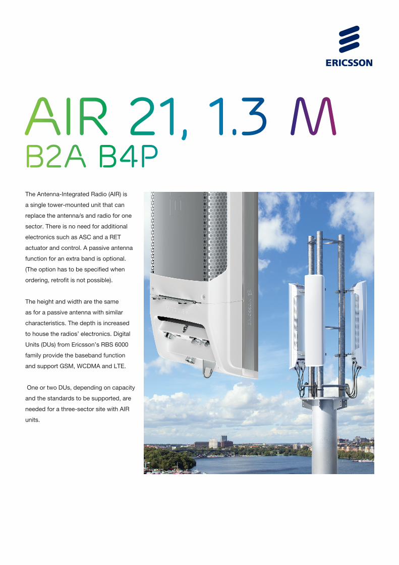
AiR 21, 1.3 MB2A B4PThe Antenna-Integrated Radio (AIR) is
a single tower-mounted unit that can
replace the antenna/s and radio for one
sector. There is no need for additional
electronics such as ASC and a RET
actuator and control. A passive antenna
function for an extra band is optional.
(The option has to be specified when
ordering, retrofit is not possible).
The height and width are the same
as for a passive antenna with similar
characteristics. The depth is increased
to house the radios’ electronics. Digital
Units (DUs) from Ericsson’s RBS 6000
family provide the baseband function
and support GSM, WCDMA and LTE.
One or two DUs, depending on capacity
and the standards to be supported, are
needed for a three-sector site with AIR
units.

Telefonaktiebolaget LM Ericsson
SE-126 25 Stockholm, Sweden
Telephone +46 8 719 0000
Fax +46 8 18 40 85
www.ericsson.com
12/287 01-FGB 101 558 RevB1
© Ericsson 2012
TECHNICAL SPECIFICATIONS AIR 21, 1.3M, B2A B4P
RADIOActive frequency band: Band 2 (1850-1910 / 1930-1990 MHz)Passive frequency band (optional): Band 4 (1710-1755 / 2110-2155 MHz)Downlink EIRP in bore-sight direction for the active band: 2 x 62,5 dBmUplink sensitivity: TBD*Remote electrical tilt: -2° to -12°, independently controlled per frequency bandMIMO: 2 x 2 for DL 4 RX branches to be used for diversity/ beam-steering /MIMOInstantaneous bandwidth: 20 MHzCapacity (single standard per sector): Up to 8 carriers GSM Up to 4 carriers WCDMA with 2 x 2 DL MIMO Up to 20 MHz LTE with 2 x 2 DL MIMO Multi-RAT capability: Single standard or two simultaneous standards (Capacity above is reduced for multi-RAT)Bore-sight antenna gain for passive antenna option: 17.5 dBiNominal beam-width, azimuth: 65°Nominal beam-width, elevation: 7°Additional antenna parameters: See Antenna characteristics, page 3
MECHANICAL SPECIFICATIONWeight (excl. mounting brackets): 37,5 kg for active only 41,5 kg for active and passiveSize (H x W x D) 1422 mm x 307 mm x 200 mmWind load: 580 N / 300 N / 720 N (frontal/lateral/rear-side) @ 42 m/s wind speed
INTERFACESAIR – DU: DATA 1, Data 2: CPRI links (SFP modules with LC socket + flanges that match protective cover TYCO C20611458)Power: - 48 V DC (TYCO/Ericsson RPT 447 04)Passive antenna (option). TX/RX 1, TX/RX 2: RF connectors (7-16 female) LMU RX sharing RX1, RX2:, RF connectors (N female)
SUPPORTING BASE-BANDRBS 6601: One or two units depending on configuration.
* 1 dB better than best-in-class RRU connected to same size best-in-class antenna
** Other base-band configurations are available

AIR-32 1.4m, data sheet rev A www.ericsson.com © Ericsson AB, 2015
AIR-32 B4A/B2P & B2A/B66Aa Ericsson Antenna Integrated Radio AIR-32
Radio Single Band (B4a/B2p) Dual Band (B2a/B66Aa)
Band 2 (1850-1910 / 1930-1990 MHz) Passive frequency band Active frequency band
Band 4 (1710-1755 / 2110-2155 MHz) Active frequency band Subset of Band 66A (AWS 1+3)
Band 66A (1710-1780 / 2110-2180 MHz) N/A Active frequency band
PA Output Power 4 x 30W 2 x (4 x 30) W
Downlink EIRP in bore-sight direction for
each active band
4 x 62.5 dBmi 4 x 62.5 dBmi
Instantaneous bandwidth 45 MHz (W, L) B2: 40 MHz (W, L)
B2: 20 MHz (G)
B66A: 70 MHz (W, L)
Capacity (single standard per unit) 6 GSM
6 WCDMA
2 x 20 MHz LTE
6 GSM (B2 only)
6 WCDMA per Active frequency band
2 x 20 MHz LTE per band
Multi-RAT capability WCDMA and LTE on both
PAs
WCDMA and GSM on both PAs (B2 only)
WCDMA and LTE on both PAs (B2 and B4)
GSM and LTE (B2 only)

AIR-32 1.4m, data sheet rev A www.ericsson.com © Ericsson AB, 2015
Interfaces Optical CPRI 2 x 10 Gbps 2 x 10 Gbps per Active frequency band
DC Power -48 VDC 3-wire or 2-wire -48 VDC 3-wire or 2-wire (separate input for
both radios)
AC power (Optional) PSU-AC 08 PSU-AC 08
Passive antenna 4 RF connectors (7/16
female)
N/A
Environmental Operating Temperature Range -40 to +55 °C -40 to +55 °C
Solar Radiation ≤ 1,120 W/m² ≤ 1,120 W/m²
Relative Humidity 5 to 100% 5 to 100%
Absolute Humidity 0.26 to 40 g/m3 0.26 to 40 g/m
3
Maximum temperature change 1.0°C/min 1.0°C/min
Antenna
Electrical Tilt 2º – 12º (B4)
2º – 12º (B2)
2º – 12º (B66A)
2º – 12º (B2)
Bore-sight antenna gain 18 dBi (B4)
17.5 dBi (B2)
18 dBi (B66A)
17.5 dBi (B2)
Nominal beam-width, azimuth 65º (B4)
63º (B2)
65º (B66A)
63º (B2)
Nominal beam-width, elevation 6º (B4)
6º (B2)
6º (B66A)
6º (B2)
Mechanical Weight 48 Kg (105.8 lbs) 60 Kg (132.2 lbs)
Dimensions (H x W x D) 1439 x 327 x 220 mm
(56.6” x 12.9” x 8.7”)
1439 x 327 x 220 mm
(56.6” x 12.9” x 8.7”)
Wind load at 42 m/s (150 km/h)
Front / Lateral / Rear
640N / 300N / 660N
640N / 300N / 660N

Technical Features
FEATURES / BENEFITS
This antenna provides a 8 Port multi-band flexible platform for advanced use for flexible use in deployment scenarios for encompassing 600MHz, 700MHz, AWS & PCS applications.
24 Inch Width For Easier ZoningField Replaceable (Integrated) AISG RET platform for reduced environmental exposure and long lasting qualitySuperior elevation pattern performance across the entire electrical down tilt rangeIncludes three AISG RET motors - Includes 0.5m AISG jumper for optional diasy chain of two high band RET motors for one single AISG point of high band tilt control.Low band arrays driven by a single RET motor
LOW BAND LEFT ARRAY (617-746 MHZ) [R1]Frequency Band MHz 617-698 698-746Gain dBi 15.1 15.5Horizontal Beamwidth @3dB Deg 65 62Vertical Beamwidth @3dB Deg 11.4 10.4Electrical Downtilt Range Deg 0-12 0-12Upper Side Lobe Suppression 0 to +20 dB 19 20
Front-to-Back, at +/-30°, Copolar dB 25 24
Cross Polar Discrimination (XPD) @ Boresight dB 19 19
Cross Polar Discrimination (XPD) @ +/-60 dB 5 3
3rd Order PIM 2 x 43dBm dBc -153VSWR - 1.5:1 1.5:1Cross Polar Isolation dB 25 25Maximum Effective Power per Port Watt 250 250
LOW BAND RIGHT ARRAY (617-746 MHZ) [R2]Frequency Band MHz 617-698 698-746Gain dBi 14.8 15.1Horizontal Beamwidth @3dB Deg 65 62Vertical Beamwidth @3dB Deg 11.4 10.3Electrical Downtilt Range Deg 0-12 0-12Upper Side Lobe Suppression 0 to +20 dB 19 20
Front-to-Back, at +/-30°, Copolar dB 25 23
Cross Polar Discrimination (XPD) @ Boresight dB 19 19
Cross Polar Discrimination (XPD) @ +/-60 dB 5 3
3rd Order PIM 2 x 43dBm dBc -153VSWR - 1.5:1 1.5:1Cross Polar Isolation dB 25 25Maximum Effective Power per Port Watt 250 250
APXVAARR24_43-U-NA20 www.rfsworld.comREV: C REV DATE: Dec 1, 2017
All information contained in the present datasheet is subject to confirmation at time of ordering Page 1 of 4
PRODUCT DATASHEET
APXVAARR24_43-U-NA20
Dual Slant Polarized Quad Band (8 Port) Antenna, 617-746/617-746/1695-2200/1695-2200MHz, 65deg, 15/15/18/18dBi, 2.4m (8ft), VET, RET, 0-12°/0-12°/2-12°/2-12°

ORDERING INFORMATIONOrder No. Configuration Mounting Hardware Mounting pipe Diameter Shipping WeightAPXVAARR24_43-U-NA20 Field Replace RET included (3) APM40-5E Beam tilt kit
(included)60-120mm 80 Kg
ELECTRICAL SPECIFICATIONSImpedance Ohm 50.0Polarization Deg ±45°
MECHANICAL SPECIFICATIONSDimensions - H x W x D mm (in) 2436 x 609 x 222 (95.9 x 24 x 8.7)Weight (Antenna Only) kg (lb) 58 (128)Weight (Mounting Hardware only)
kg (lb) 11.5 (25.3)
Shipping Weight kg (lb) 80 (176)Connector type 8 x 4.3-10 female at bottom + 6 AISG connectors (3 male, 3 female)Adjustment mechanism Integrated RET solution AISG compliant (Field Replaceable) + Manual Override + External Tilt IndicatorMounting Hardware Material
Galvanized steel
Radome Material / Color Fiber Glass / Light Grey RAL7035
TESTING AND ENVIRONMENTALTemperature Range °C (°F) -40 to 60 (-40 to 140 )Lightning protection IEC 61000-4-5Survival/Rated Wind Velocity
km/h 241 (150 )
Environmental ETSI 300-019-2-4 Class 4.1E
APXVAARR24_43-U-NA20 www.rfsworld.comREV: C REV DATE: Dec 1, 2017
All information contained in the present datasheet is subject to confirmation at time of ordering Page 3 of 4
PRODUCT DATASHEET
APXVAARR24_43-U-NA20
Dual Slant Polarized Quad Band (8 Port) Antenna, 617-746/617-746/1695-2200/1695-2200MHz, 65deg, 15/15/18/18dBi, 2.4m (8ft), VET, RET, 0-12°/0-12°/2-12°/2-12°

Improving a radio uplink by using tower mounted amplifiers is perceived as a key method of optimiz-ing radio networks. By ensuring maximum coverage including in-door penetration, a TMA supports the design of cost-efficient networks and extended talk-time handsets, low dropped call rates and high traffic billing.
TMA designThis Double Premium TMA for 17/2100 MHz has 12dB gain and is 3GPP/AISG 2.0 compatible, with a RET interface. It has superior RF performance, small size and low weight. There is a corresponding TMA ver-sion called ASC that has a higher gain and a VSWR measuring coupler.
System integrationThe Double TMA 17/2100 is a part of Ericsson’s TMA family. Power, control and supervision are provided by the RBS 3000. If sold to other RBS brand installations,
it can be controlled and supervised from the “Antenna System & TMA Control Module”, AST-CM, via the RF feeder.
3GPP/AISGTMA communication is based on the 3GPP/AISG protocol standard and has a RET port for controlling antenna RET units. The communication port allows multiple RETs or Antenna Line Devices to be supervised and controlled via the TMA.
Future-proofThe Double TMA 17/21 Premium is designed for co-exis-tence with future complementary, mast-mounted devices.
Excellent reliabilityAs the world’s largest supplier of TMAs, Ericsson has a well-proven track record of reliable TMA designs. Reliabil-ity enhancing features include dual LNAs, weatherproof design, integrated alarm and lightning protection.
DOUBLE TMA 17/21, PREMIUM
3GPP/AISG compatible with RET interface

Features• Specified and verified as an integrated system solution for Ericsson RBSs
• Possible to power both TMAs from one feeder, or from both feeders
• High power capacity
• Automatic LNA by-pass function
• Built in lightning protection
• Excellent RF performance
• Connectors “in line”
• Distance between connectors simplifies sealing work
• A range of accessories for flexible site configurations
36/287 01 - FGC 101 764, rev A© Ericsson AB, 2008
Product name Product numberDouble TMA 17/21, Premium KRY 112 144/13GPP/ASIG compatible with RET interface
Radio performanceBandwidth: 45 MHzReceiving pass band: 1710 - 1755 MHzTransmitting pass band: 2110 - 2155 MHzRX Gain: 12± 1 dBInput IP3: 16 dBm*IM3 at antenna port (2x43dBM): -128 dBmNoise figure midband: 1.0 dB*TX max input power (Max Peak): 57 dBmTX insertion loss: 0.25 dB*RX return loss: 22 dB*TX return loss: 22 dB*
Electrical specificationsInput power: +12 - 32 VDCPower consumption: < 4.5 W
Mechanical specificationsDimensions (W x H x D): 155 x 176 x 71 mmWeight: 5 kgRF connectors: 7-16 DIN femaleGround connectors: M8DC/Alarm: Superimposed on the RF signalMounting: Pole or wall mountingRET connectors: Din con. IEC 60130-9 - Ed. 3.0 female
Environmental specificationsTemperature range, full performance: -40ºC - +55ºCMTBF: 80 yearsSealing: IP67Lightning protection: IEC 62305-1, IEC 61000-6Safety approval: International: CB certified, IEC 60 529 Europe: EN 60 529 North America: NRTL, NEMA 3R Safety standard: UL 60950-1, IEC 60950-1
Technical Specifications for Double TMA 1700/2100, MHz Premium
Ericsson ABwww.ericsson.com S
ubje
ct to
cha
nge
with
out n
otic
e
* Typical values
190 mm (7
.5 in)
86 mm (3.4 in)
195 mm (7.7 in)
190 mm (7
.5 in)

Dual Band Radio 4449 B12,B71 | Commercial in confidence | © Ericsson AB 2017 | 2017-09-29 | Page 1
Dual Band Radio 4449 B12,B71
T-Mobile
Jadran Lokas
Sep. 29, 2017

Dual Band Radio 4449 B12,B71 | Commercial in confidence | © Ericsson AB 2017 | 2017-09-29 | Page 5
Building practice concept
Optimized for dual band
Target size:
• Volume: 30+L
• 335mm width; 379.7mm height; 235+mm depth
• Weight: 74 lb +/- 4lb (33.6Kg +/- 1.8kg)
• 58+mm fin height
Filter double-sided chassis in-between B12 and B71 Radio boards
B71 Master board
B12 slave board

Technical Data Sheet SC2-W100AB (Cont.)
CompactLine Easy Antenna, Single Polarized, 2 ft10.0 - 11.7 GHz
Allinformationcontainedinthepresentdatasheetissubjecttoconfirm
ationattim
eofordering
RFS The Clear Choice ™ SC2-W100AB Print Date: 18.05.2012Please visit us on the internet at http://www.rfsworld.com/ Radio Frequency Systems
FST Side force max. at 110 km/h (68 mph), N (lb) 136 (31)FAT Axial force max. at 110 km/h (68 mph), N (lb) 274 (62)M Torque max. at 110 km/h (68 mph), Nm (ft lb) 79 (58)FST Side force max. at 200 km/h (125 mph), N (lb) 448 (101)FAT Axial force max. at 200 km/h (125 mph), N (lb) 905 (203)M Torque max. at 200 km/h (125 mph), Nm (ft lb) 262 (193)
All dimensions in mm (in)ØA B C ØD for mounting pipe diam. E F
219 (8.5) 114 (4.5) 89 (3.5) 51 (2.0)
670 (26.4) 293 (11.5) 254 (10) 293 (11.4) 293 (11.4) 293 (11.4) 123 (4.8) 100 (3.9)
Notesno notes
DocumentationRPE (10.55-10.68 GHz) (NSMA format)SC2-W100A (10.55-10.68 GHz), 110805.txtRPE (10.55-10.68 GHz) (PDF format)SC2-W100A (10.55-10.68 GHz), 110805.pdf
Radiation pattern: (NSMA format)SC2-W100A (10.0-11.7 GHz), 110803.txtRadiation pattern: (PDF Format)SC2-W100A (10.0-11.7 GHz), 110803.pdf


EBI Consulting environmental | engineering | due diligence
21 B Street . Burlington, MA 01803 . Tel: (781) 273.2500 . Fax: (781) 273.3311
RADIO FREQUENCY EMISSIONS ANALYSIS REPORT EVALUATION OF HUMAN EXPOSURE POTENTIAL
TO NON-IONIZING EMISSIONS
T-Mobile Existing Facility
Site ID: CTHA174A
33 Mitchell Drive_Manchester CT 33 Mitchell Drive
Manchester, CT 06042
March 15, 2018
EBI Project Number: 6218001985
Site Compliance Summary
Compliance Status: COMPLIANT
Site total MPE% of FCC general population
allowable limit:
3.90 %

EBI Consulting environmental | engineering | due diligence
21 B Street . Burlington, MA 01803 . Tel: (781) 273.2500 . Fax: (781) 273.3311
March 15, 2018
T-Mobile USA
Attn: Jason Overbey, RF Manager
35 Griffin Road South
Bloomfield, CT 06002
Emissions Analysis for Site: CTHA174A – 33 Mitchell Drive_Manchester CT
EBI Consulting was directed to analyze the proposed T-Mobile facility located at 33 Mitchell Drive,
Manchester, CT, for the purpose of determining whether the emissions from the Proposed T-Mobile
Antenna Installation located on this property are within specified federal limits.
All information used in this report was analyzed as a percentage of current Maximum Permissible
Exposure (% MPE) as listed in the FCC OET Bulletin 65 Edition 97-01and ANSI/IEEE Std C95.1. The
FCC regulates Maximum Permissible Exposure in units of microwatts per square centimeter (W/cm2).
The number of W/cm2 calculated at each sample point is called the power density. The exposure limit
for power density varies depending upon the frequencies being utilized. Wireless Carriers and Paging
Services use different frequency bands each with different exposure limits, therefore it is necessary to
report results and limits in terms of percent MPE rather than power density.
All results were compared to the FCC (Federal Communications Commission) radio frequency exposure
rules, 47 CFR 1.1307(b)(1) – (b)(3), to determine compliance with the Maximum Permissible Exposure
(MPE) limits for General Population/Uncontrolled environments as defined below.
General population/uncontrolled exposure limits apply to situations in which the general population may
be exposed or in which persons who are exposed as a consequence of their employment may not be made
fully aware of the potential for exposure or cannot exercise control over their exposure. Therefore,
members of the general population would always be considered under this category when exposure is not
employment related, for example, in the case of a telecommunications tower that exposes persons in a
nearby residential area.
Public exposure to radio frequencies is regulated and enforced in units of microwatts per square
centimeter (μW/cm2). The general population exposure limits for the 600 MHz and 700 MHz Band are
approximately 400 μW/cm2 and 467 μW/cm2 respectively. The general population exposure limit for the
1900 MHz (PCS), 2100 MHz (AWS) and 10 GHz Microwave bands is 1000 μW/cm2. Because each
carrier will be using different frequency bands, and each frequency band has different exposure limits, it
is necessary to report percent of MPE rather than power density.

EBI Consulting environmental | engineering | due diligence
21 B Street . Burlington, MA 01803 . Tel: (781) 273.2500 . Fax: (781) 273.3311
Occupational/controlled exposure limits apply to situations in which persons are exposed as a
consequence of their employment and in which those persons who are exposed have been made fully
aware of the potential for exposure and can exercise control over their exposure. Occupational/controlled
exposure limits also apply where exposure is of a transient nature as a result of incidental passage through
a location where exposure levels may be above general population/uncontrolled limits (see below), as
long as the exposed person has been made fully aware of the potential for exposure and can exercise
control over his or her exposure by leaving the area or by some other appropriate means.
Additional details can be found in FCC OET 65.
CALCULATIONS
Calculations were done for the proposed T-Mobile Wireless antenna facility located at 33 Mitchell Drive,
Manchester, CT, using the equipment information listed below. All calculations were performed per the
specifications under FCC OET 65. Since T-Mobile is proposing highly focused directional panel
antennas, which project most of the emitted energy out toward the horizon, all calculations were
performed assuming a lobe representing the maximum gain of the antenna per the antenna manufactures
supplied specifications, minus 10 dB for directional panel antennas and 20 dB for highly focused
parabolic microwave dishes, was focused at the base of the tower. For this report the sample point is the
top of a 6-foot person standing at the base of the tower.
For all calculations, all equipment was calculated using the following assumptions:
1) 2 GSM channels (PCS Band - 1900 MHz) were considered for each sector of the proposed
installation. These Channels have a transmit power of 30 Watts per Channel.
2) 2 UMTS channels (PCS Band - 1900 MHz) were considered for each sector of the proposed
installation. These Channels have a transmit power of 30 Watts per Channel.
3) 2 UMTS channels (AWS Band – 2100 MHz) were considered for each sector of the proposed
installation. These Channels have a transmit power of 30 Watts per Channel.
4) 2 LTE channels (PCS Band - 1900 MHz) were considered for each sector of the proposed
installation. These Channels have a transmit power of 60 Watts per Channel.
5) 2 LTE channels (AWS Band – 2100 MHz) were considered for each sector of the proposed
installation. These Channels have a transmit power of 60 Watts per Channel
6) 1 LTE channel (600 MHz Band) was considered for each sector of the proposed installation.
This channel has a transmit power of 30 Watts.

EBI Consulting environmental | engineering | due diligence
21 B Street . Burlington, MA 01803 . Tel: (781) 273.2500 . Fax: (781) 273.3311
7) 1 LTE channel (700 MHz Band) was considered for each sector of the proposed installation.
This channel has a transmit power of 30 Watts.
8) 1 microwave backhaul channel (10GHz) was considered for the proposed facility. This
channel has a transmit power of 1 Watt.
9) All radios at the proposed installation were considered to be running at full power and were
uncombined in their RF transmissions paths per carrier prescribed configuration. Per FCC
OET Bulletin No. 65 - Edition 97-01 recommendations to achieve the maximum anticipated
value at each sample point, all power levels emitting from the proposed antenna installation
are increased by a factor of 2.56 to account for possible in-phase reflections from the
surrounding environment. This is rarely the case, and if so, is never continuous.
10) For the following calculations the sample point was the top of a 6-foot person standing at the
base of the tower. The maximum gain of the antenna per the antenna manufactures supplied
specifications, minus 10 dB for directional panel antennas and 20 dB for highly focused
parabolic microwave dishes, was used in this direction. This value is a very conservative
estimate as gain reductions for these particular antennas are typically much higher in this
direction.
11) The antennas used in this modeling are the Ericsson AIR32 B66A/B2A & Ericsson AIR21
B2A/B4P for 1900 MHz (PCS) and 2100 MHz (AWS) channels, the RFS APXVAA24-43-
U-A20 for 600 MHz and 700 MHz channels and the Commscope SC2-W100AB for the
proposed 10 GHz microwave backhaul. This is based on feedback from the carrier with
regard to anticipated antenna selection. The Ericsson AIR32 B66A/B2A has a maximum
gain of 15.9 dBd at its main lobe at 1900 MHz and 2100 MHz. The Ericsson AIR21
B2A/B4P has a maximum gain of 15.9 dBd at its main lobe at 1900 MHz and 2100 MHz.
The RFS APXVAA24-43-U-A20 has a maximum gain of 13.15 and 13.55 dBd at its main
lobe at 600 MHz and 700 MHz respectively. The maximum gain of the antenna per the
antenna manufactures supplied specifications, minus 10 dB for directional panel antennas and
20 dB for highly focused parabolic microwave dishes, was used for all calculations. This
value is a very conservative estimate as gain reductions for these particular antennas are
typically much higher in this direction.
12) The antenna mounting height centerline of the proposed antennas (both panel antennas and
microwave dish) is 140 feet above ground level (AGL).

EBI Consulting environmental | engineering | due diligence
21 B Street . Burlington, MA 01803 . Tel: (781) 273.2500 . Fax: (781) 273.3311
13) Emissions values for additional carriers were taken from the Connecticut Siting Council
active database. Values in this database are provided by the individual carriers themselves.
14) All calculations were done with respect to uncontrolled / general population threshold limits.

EBI Consulting environmental | engineering | due diligence
21 B Street . Burlington, MA 01803 . Tel: (781) 273.2500 . Fax: (781) 273.3311
T-Mobile Site Inventory and Power Data
Microwave Backhaul Data Make /
Model: Gain
Height
(AGL):
Frequency
Bands
Channel
Count
Total TX
Power(W) ERP (W) MPE % Sector
Commscope
SC2-100AB 32.85 dBd 140 10 GHz 1 1 1717.91 0.03 A
Sector: A Sector: B Sector: C Sector: D
Antenna #: 1 Antenna #: 1 Antenna #: 1 Antenna #: 1
Make / Model: Ericsson AIR32
B66A/B2A Make / Model:
Ericsson AIR32 B66A/B2A
Make / Model: Ericsson AIR32
B66A/B2A Make / Model:
Ericsson AIR32 B66A/B2A
Gain: 15.9 dBd Gain: 15.9 dBd Gain: 15.9 dBd Gain: 15.9 dBd
Height (AGL): 140 Height (AGL): 140 Height (AGL): 140 Height (AGL): 140
Frequency Bands 1900 MHz (PCS) / 2100 MHz (AWS)
Frequency Bands 1900 MHz (PCS) / 2100 MHz (AWS)
Frequency Bands 1900 MHz (PCS) / 2100 MHz (AWS)
Frequency Bands 1900 MHz (PCS) / 2100 MHz (AWS)
Channel Count 4 Channel Count 4 Channel Count 4 Channel Count 4
Total TX
Power(W): 240
Total TX
Power(W): 240
Total TX
Power(W): 240
Total TX
Power(W): 240
ERP (W): 9,337.08 ERP (W): 9,337.08 ERP (W): 9,337.08 ERP (W): 9,337.08
Antenna A1
MPE% 1.87
Antenna B1
MPE% 1.87
Antenna C1
MPE% 1.87
Antenna D1
MPE% 1.87
Antenna #: 2 Antenna #: 2 Antenna #: 2 Antenna #: 2
Make / Model: Ericsson AIR21
B2A/B4P Make / Model:
Ericsson AIR21
B2A/B4P Make / Model:
Ericsson AIR21
B2A/B4P Make / Model:
Ericsson AIR21
B2A/B4P
Gain: 15.9 dBd Gain: 15.9 dBd Gain: 15.9 dBd Gain: 15.9 dBd
Height (AGL): 140 Height (AGL): 140 Height (AGL): 140 Height (AGL): 140
Frequency Bands 1900 MHz (PCS) / 2100 MHz (AWS)
Frequency Bands 1900 MHz (PCS) / 2100 MHz (AWS)
Frequency Bands 1900 MHz (PCS) / 2100 MHz (AWS)
Frequency Bands 1900 MHz (PCS) / 2100 MHz (AWS)
Channel Count 6 Channel Count 6 Channel Count 6 Channel Count 6
Total TX
Power(W): 180
Total TX
Power(W): 180
Total TX
Power(W): 180
Total TX
Power(W): 180
ERP (W): 7,002.81 ERP (W): 7,002.81 ERP (W): 7,002.81 ERP (W): 7,002.81
Antenna A2
MPE% 1.40
Antenna B2
MPE% 1.40
Antenna C2
MPE% 1.40
Antenna D2
MPE% 1.40
Antenna #: 3 Antenna #: 3 Antenna #: 3 Antenna #: 3
Make / Model: RFS APXVAA24-
43-U-A20 Make / Model:
RFS APXVAA24-
43-U-A20 Make / Model:
RFS APXVAA24-
43-U-A20 Make / Model:
RFS APXVAA24-
43-U-A20
Gain: 13.15/ 13.55 dBd Gain: 13.15/ 13.55 dBd Gain: 13.15/ 13.55 dBd Gain: 13.15/ 13.55 dBd
Height (AGL): 140 Height (AGL): 140 Height (AGL): 140 Height (AGL): 140
Frequency Bands 700 MHz Frequency Bands 700 MHz Frequency Bands 700 MHz Frequency Bands 700 MHz
Channel Count 1 Channel Count 1 Channel Count 1 Channel Count 1
Total TX
Power(W): 30
Total TX
Power(W): 30
Total TX
Power(W): 30
Total TX
Power(W): 30
ERP (W): 679.39 ERP (W): 679.39 ERP (W): 679.39 ERP (W): 679.39
Antenna A3
MPE% 0.60
Antenna B3
MPE% 0.60
Antenna C3
MPE% 0.60
Antenna D3
MPE% 0.60
Site Composite MPE%
Carrier MPE%
T-Mobile (Sector A) 3.90 %
No Additional Carriers Listed in the CSC Active MPE
database NA
Site Total MPE %: 3.90 %
T-Mobile Sector A Total: 3.90%
T-Mobile Sector B Total: 3.87 %
T-Mobile Sector C Total: 3.87%
Site Total: 3.90 %

EBI Consulting environmental | engineering | due diligence
21 B Street . Burlington, MA 01803 . Tel: (781) 273.2500 . Fax: (781) 273.3311
T-Mobile Max Power Values (Sector A)
T-Mobile _Max Power Values (Sector A)
#
Channels
Watts ERP
(Per Channel)
Height
(feet)
Total Power
Density
(W/cm2)
Frequency
(MHz)
Allowable
MPE
(W/cm2)
Calculated %
MPE
T-Mobile AWS - 2100 MHz LTE 2 2,334.27 140 9.35
AWS - 2100
MHz 1000 0.93%
T-Mobile PCS - 1900 MHz LTE 2 2,334.27 140 9.35
PCS - 1900
MHz 1000 0.93%
T-Mobile AWS - 2100 MHz UMTS 2 1,167.14 140 4.67
AWS - 2100
MHz 1000 0.47%
T-Mobile PCS - 1900 MHz UMTS 2 1,167.14 140 4.67
PCS - 1900
MHz 1000 0.47%
T-Mobile PCS - 1900 MHz GSM 2 1,167.14 140 4.67
PCS - 1900
MHz 1000 0.47%
T-Mobile 600 MHz LTE 1 619.61 140 1.24 600 MHz 400 0.31%
T-Mobile 700 MHz LTE 1 679.39 140 1.36 700 MHz 467 0.29%
T-Mobile 10 GHz Microwave 1 1717.91 140 0.34 10 GHz 1000 0.03%
Total: 3.90%

EBI Consulting environmental | engineering | due diligence
21 B Street . Burlington, MA 01803 . Tel: (781) 273.2500 . Fax: (781) 273.3311
Summary
All calculations performed for this analysis yielded results that were within the allowable limits for
general population exposure to RF Emissions.
The anticipated maximum composite contributions from the T-Mobile facility as well as the site
composite emissions value with regards to compliance with FCC’s allowable limits for general population
exposure to RF Emissions are shown here:
T-Mobile Sector Power Density Value (%)
Sector A: 3.90%
Sector B: 3.87 %
Sector C: 3.83 %
T-Mobile Per Sector
Maximum (Sector A): 3.90 %
Site Total: 3.90 %
Site Compliance Status: COMPLIANT
The anticipated composite MPE value for this site assuming all carriers present is 3.90% of the allowable
FCC established general population limit sampled at the ground level. This is based upon values listed in
the Connecticut Siting Council database for existing carrier emissions.
FCC guidelines state that if a site is found to be out of compliance (over allowable thresholds), that
carriers over a 5% contribution to the composite value will require measures to bring the site into
compliance. For this facility, the composite values calculated were well within the allowable 100%
threshold standard per the federal government.


![[PROGRAMME] NTOIN FOR UERAY : LOUIS COUPERIN UITE EN … · 2016-07-13 · [programme] ntoin for ueray : louis couperin uite en so wi -ur jeÂnlphilippe ramea —2>ü-jl en la louis](https://static.fdocuments.us/doc/165x107/5f4c7021c68e79517b6d1540/programme-ntoin-for-ueray-louis-couperin-uite-en-2016-07-13-programme-ntoin.jpg)