s r o t a r e n e G l e s e i D r o t i n EAOM-19 72 x 72...
43
EAOM-19 72 x 72, - Automatic engine start / stop - Generator voltage and frequency measurement and monitoring - Battery voltage measurement and monitoring - Simple push-button controlled operation - Two user configurable inputs - Provides charge generator excitation current - Speed sensing from alternator frequency - Fully programmable Automatic Transfer Unit For Diesel Generators - Led status and fault indication - Mains voltage measurement and monitoring (Ph-Ph or Ph-N) - Automatic shutdown on fault condition EAOM-19 Automatic Transfer Unit For Diesel Generators
Transcript of s r o t a r e n e G l e s e i D r o t i n EAOM-19 72 x 72...

EAOM-19 72 x 72,
- Automatic engine start / stop
- Generator voltage and frequency measurement and monitoring
- Battery voltage measurement and monitoring
- Simple push-button controlled operation
- Two user configurable inputs
- Provides charge generator excitation current
- Speed sensing from alternator frequency
- Fully programmable
Automatic Transfer Unit For Diesel Generators
- Led status and fault indication
- Mains voltage measurement and monitoring (Ph-Ph or Ph-N)
- Automatic shutdown on fault condition
EA
OM
-19
A
uto
ma
tic
Tra
ns
fer
Un
it F
or
Die
se
l G
en
era
tors

2
Instruction manual of EAoM-19 automatic transfer unit consists of two main sections. Explanation of these sections are below. Also, there is other section which include technical specifications of the unit. All titles and page numbers in instruction manual are in “CONTENTS” section. User can reach to any title with page number.
Installation:
In this section, physical dimensions of the unit, panel mounting, electrical connections, physical and electrical installation of the unit to the system are explained.
Operation and Parameters:
In this section, user interface of the unit, how to access to the parameters, description of parameters are explained.
Also in these sections, there are warnings to prevent serious injury while doing the physical and electrical mountage or using the unit.
Explanation of the symbols which are used in these sections are given below.
This stmbol is used to determine the dangerous situations as a result of an electrical shock. User must pay attention to these warnings definitely.a
c This symbol is used for security warnings. User must pay attention to these warnings.
This symbol is used to determine the important notes about functions and usage of the unit.
ABOUT INSTRUCTION MANUAL
i

1.INTRODUCTION................................................................................................................................1.1 GENERAL SPECIFICATIONS...................................................................................................1.2 WARRANTY...............................................................................................................................1.3 MAINTENANCE.........................................................................................................................
2.INSTALLATION..................................................................................................................................2.1 GENERAL DESCRIPTION........................................................................................................2.2 DIMENSIONS............................................................................................................................2.3 PANEL CUT-OUT.......................................................................................................................2.4 ENVIRONMENTAL RATINGS....................................................................................................2.5 PANEL MOUNTING...................................................................................................................2.6 INSTALLATION FIXING CLAMP................................................................................................2.7 REMOVING FROM THE PANEL...............................................................................................
3.ELECTRICAL CONNECTIONS..........................................................................................................3.1 TERMINAL LAYOUT AND CONNECTION INSTRUCTIONS....................................................3.2 ELEKTRICAL CONNECTION DIAGRAM..................................................................................
3.2.1 EAOM-19 SINGLE PHASE CONNECTIONS SCHEMATIC FOR TN-C AC POWER SYSTEMS........................................................................................................................
3.2.2 EAOM-19 THREE PHASE CONNECTIONS SCHEMATIC FOR TN-C AC POWER SYSTEMS........................................................................................................................
3.3 TOP LABEL VIEW OF THE EAOM-19......................................................................................3.4 UNIT WIRING............................................................................................................................3.5 UNIT WIRING DESCRIPTION..................................................................................................
4.DEFINITION OF FRONT PANEL AND ACCESSING TO THE PARAMETERS................................4.1 FRONT PANEL DESCRIPTION................................................................................................4.2 ACCESSING TO THE OPERATOR PARAMETERS.................................................................4.3 ACCESSING TO THE TECHNICIAN PARAMETERS...............................................................4.4 PARAMETER LIST....................................................................................................................4.5 EXPLANATION OF PARAMETERS..........................................................................................
4.5.1 MAINS VOLTAGE CONNECTION (P00) AND DISCONNECTION LEVEL (P01), UPPER LIMIT (P02).........................................................................................................
4.5.2 ALTERNATOR VOLTAGE LOWER (P03) AND UPPER LIMIT (P04), FAULT CONTROL DELAY (P20)....................................................................................................................
4.5.3 ALTERNATOR FREQUENCY UPPER LIMIT (P05), FAULT CONTROL DELAY (P21)....4.5.4 ENGINE COOLING TIME (P07).......................................................................................4.5.5 MAINS TRANSITION DELAY (P09).................................................................................4.5.6 BATTERY VOLTAGE LOWER LIMIT (P11)......................................................................4.5.7 STOP / FUEL SOLENOID SELECTION (P13).................................................................4.5.8 STOP MAGNET ENERGISED TIME (P14)......................................................................4.5.9 ENGINE STARTED SIGNAL (P15)................................................................................4.5.10 STARTING ATTEMPT DURATION(P16), NUMBER OF STARTING ATTEMPTS(P06)..4.5.11 CONTROL ON DELAY (P19)..........................................................................................4.5.12 CONFIGURABLE INPUTS 1 AND 2 (P22 AND P23).....................................................
4.5.17 OPERATOR PASSWORD (P28)....................................................................................4.5.18 TECHNICIAN PASSWORD (P29)..................................................................................
5.COMMISSIONING..............................................................................................................................5.1 MANUAL MODE........................................................................................................................5.2 AUTO MODE.............................................................................................................................5.3 TEST MODE..............................................................................................................................
6.OPERATION.......................................................................................................................................6.1 ALTERNATE DISPLAY DESCRIPTION.....................................................................................6.2 FAILURE INDICATORS DESCRIPTION...................................................................................6.3 MODE TRANSITION.................................................................................................................6.4 MANUAL START........................................................................................................................6.5 MANUAL STOP..........................................................................................................................6.6 AUTO OPERATION...................................................................................................................6.7 TEST OPERATION....................................................................................................................
4.5.13 HORN OUTPUT SELECTION (P24)..............................................................................4.5.14 CHOKE TIME (P25).......................................................................................................4.5.15 GENERATOR START DELAY (P26)..............................................................................4.5.16 OIL SENSOR SELECTION (P27)..................................................................................
CONTENTS
3
Page 6
Page 19
Page 13
Page 8Page 9
Page 6Page 7Page 7
Page 9Page 10Page 11Page 11Page 12Page 12
Page 13Page 14
Page 14
Page 15Page 16Page 17Page 18
Page 19Page 21Page 23Page 25Page 26
Page 26
Page 27Page 27Page 27Page 27Page 27Page 27Page 28Page 28Page 28Page 29Page 29Page 29Page 29
Sayfa 33
Sayfa 31Sayfa 31Sayfa 32Sayfa 32
Sayfa 33Sayfa 36Sayfa 38Sayfa 38Sayfa 38Sayfa 38Sayfa 38
Page 30Page 30Page 30

7.FAULT FINDING.................................................................................................................................
8.SPECIFICATIONS..............................................................................................................................
9.BLOK DIAGRAM................................................................................................................................
10. USER DEFINED PARAMETERS.....................................................................................................LIST-1...............................................................................................................................................
4
Page 40
Page 43
Page 39
Page 42
Page 43

5
Manufacturer Company Name : Emko Elektronik CO.
Manufacturer Company Address: DOSAB, Karanfil Sokak, No:6, 16369 Bursa, Turkey
The manufacturer hereby declares that the product conforms to the following standards and conditions.
Product Name : Automatic Transfer Unit For Diesel Generators
Model Number : EAOM-19
Type Number : EAOM-19
Product Category : Electrical equipment for measurement, control and laboratory use
Conforms to the following directives :
73 / 23 / EEC The Low Voltage Directive as amended by 93 / 68 / EEC
89 / 336 / EEC The Electromagnetic Compatibility Directive
Has been designed and manufactured according to the following specifications
EN 61000-6-4 EMC Generic Emission Standard for the Industrial Environment
EN 61000-6-2 EMC Generic Immunity Standard for the Industrial Environment
EN 61010-1 Safety Requirements for electrical equipment for measurement, control and laboratory use
EU DECLARATION OF CONFORMITY

1.Introduction
6
The EAOM-19 provides for automatic transfer of a load from mains to generator in the event of a mains failure. The unit is able to detect failure of any phase of the mains and to start and switch over to a generator if the mains voltage goes outside pre-set limits. Both automatic and manual control is possible. A test mode is also available which allows the generator to be run without taking the load. The unit monitors generator operation and gives warning of any faults that are detected. It monitors:
!Mains voltage! Alternator output (voltage and frequency)! Engine speed! Battery voltage! Engine temperature!Oil pressure
It controls:
! Engine fuel supply or engine stopping, (via external solenoid)! Starter motor, (via external relay)! Automatic generator start and load transfer on mains failure, (via external mains and
generator contactors)! Alarm horn
A four-digit, seven-segment display provides extensive monitoring of unit and generator parameters, including:
!Mains voltages! Alternator voltage and frequency! Battery voltage! Error indication! Program parameters
The unit is extensively programmable, with password protection on two levels. In the event that the engine fails to start on the first attempt, the attempt will be repeated a programmed number of times or until successful. If a fault is detected, the unit shuts down the engine and indicates the failure by flashing a relevant fault LED. Two user configurable inputs are included that sound an external horn, flash indicators on the panel and can be programmed to stop the engine or disconnect the load.
1.1 General Specifications
7
1.2 Warranty
EMKO Elektronik warrants that the equipment delivered is free from defects in material and workmanship. This warranty is provided for a period of two years. The warranty period starts from the delivery date. This warranty is in force if duty and responsibilities which are determined in warranty document and instruction manual performs by the customer completely.
1.3 Maintenance
If the device is used with conditions which are explained in this instruction manual, there is no need to do periodic maintenance.

8
In package,- One piece unit- Two pieces fixing clamp- One piece instruction manual
A visual inspection of this product for possible damage occured during shipment is recommended before installation. It is your responsibility to ensure that qualified mechanical and electrical technicians install this product.
If there is danger of serious accident resulting from a failure or defect in this unit , power off the system and seperate the electrical connection of the device from the system.
The unit is normally supplied without a power switch or a fuse. Use power switch and fuse as required.
Be sure to use the rated power supply voltage to protect the unit against damage and to prevent failure.
Keep the power off until all of the wiring is completed so that electric shock and trouble with the unit can be prevented.
Never attempt to disassemble, modify or repair this unit. Tampering with the unit may results in malfunction, electric shock or fire.
Do not use the unit in combustible or explosive gaseous atmospheres.
During the equipment is putted in hole on the metal panel while mechanical installation some metal burrs can cause injury on hands, you must be careful.
Montage of the product on a system must be done with it’s fixing clamps. Do not do the montage of the device with in appropriate fixing clamp. Be sure that device will not fall while doing the montage.
Before beginning installation of this product, please read the instruction manual and warnings below carefully.
2.Installation
c

9
2.1 General Description
2.2 Dimensions
Maximum 15mm / 0.590 inch
72mm / 2.834 inch
72
mm
/ 2
.83
4 in
ch
83.5 mm / 3.287 inch11.5mm / 0.452 inch
Product Label
Front PanelIP65 protectionNEMA 4X
Panel Surface(maximum thickness 15mm / 0.590 inch)
Fixing Clamp
UV
z.H
O FFU O
A T
TEST
V1/L3
L3N
VL23/L2N
VL2 /L11
N
PROG
TEST RTESE
G
G
AOEM - 19
M N.AS ART T
N.MA
TOPS
~~ ~~~~~~~~~~MRP
VV
FA L DI ET ARO ST T
H GI HTEMPERATUREW OILLO PR
REESSU
O ER EV
SP EDUFAI RL
EVO
GLTA EAIL RF
U EC A GIN
H RGFAIL
VZO
AT V LB T.
T.IL REFA U
UV
Hz.
OFF AUTO
TEST
VL31/L3NVL23/L2NVL12/L1N
PROG
TEST RESET
G
G
EAOM - 19
MAN.START
MAN.STOP
~~ ~~~~~~~~~~
RPM
VV
FAILEDTO START
HIGHTEMPERATURE
LOW OILPRESSURE
OVER SPEEDFAILURE
VOLTAGEFAILURE
CHARGINGFAIL
VZBATT. VOLT.FAILURE

10
2.3 Panel Cut-Out
97 mm / 3.82 inch (min)
97
mm
/ 3
.82
in
ch
(m
in)
69
mm
/ 2
.72
in
ch
69mm / 2.72 inch

11
Operating Temperature : -25°C to +70 °C
Max. Operating Humidty : %90 Rh (non-condensing)
Altitude : Up to 2000m.
Operating Conditions
Forbidden Conditions:Corrosive atmosphereExplosive atmosphereHome applications (The unit is only for industrial applications)
2.4 Environmental Ratings
2.5 Panel Mounting
c
c
1
2
3
1-Before mounting the controller in your panel, make sure that the cut-out is of the right size.
2-Check front panel gasket position
3-Insert the device through the cut-out. If the mounting clamps are on the unit, put out them before inserting the unit to the panel.
During installation into a metal panel, care should be taken to avoid injury from metal burrs which might be present. The equipment can loosen from vibration and become dislodged if installation parts are not properly tightened. These precautions for the safety of the person who does the panel mounting.
UV
.zH
O FFAUTO
ET TS
V1 L
L / 3N3
VL2
N3/L2
V/L1
L1N
2
PROG
TTESESET
R
G
G
EAO 19
M -
N.MAT RS A T
.MANSTOP
~~ ~~~~~~~~~~ R MP
VV
FAILEDS ART
TO TIH GHE P
T M ERATUREOLOW ILREP
SSURE
EE
OV R SP EDLFAI UREVOA GE
LTFAILURE
AI
CH RG NGFAIL
VZ TBAT . VO T.LFAILURE

12
2.6 Installation Fixing Clamp
2.7 Removing from the Panel
c
1
2
Montage of the device to a system must be done with it’s own fixing clamps. Do not do the montage of the device with inappropriate fixing clamps. Be sure that device will not fall while doing the montage.
The unit is designed for panel mounting.
1-Insert the unit in the panel cut-out from the front.
2-Insert the mounting clamp from the rear side of the device and tighten the fixing screws to secure the unit against the panel.
c
3
1
2
Before starting to remove the device from panel, power off the device and the related system.
1-Loosen screws.
2-Lift the locking tabs located on both the right and left hand sides and pull the fixing clamp from the device while holding the unit in place.
3-Pull the unit through the front of the panel
VU
zH .
OFFTAU O
ET TS
V3L 1/L3N
V23 L N
L / 2
V1L 2/ 1NL
ROGP
E TT SR
ETES
G
G
OM 1EA
- 9
ANM.START
N.MASTOP
~~ ~~~~~~~~~~MPR
VV
FA LI EDST RT
TO AIGH H
T MP RATUR
EE
EO
L W LO
IP ES URR
SE
PVE S ED
OR
EF ILU EA
RV TAOL GEA LURF I
EAH
GI GC
R NF ILA
VZ TB T. OLT.A
VARE
F ILU
VU
zH .
OFFTAU O
ET ST
V3L 1/L3N
VL N
L23/ 2
V1L 2/ 1NL
R GP O
TESTRESET
G
G
E OM 1A
- 9
ANM.S AT RT
N.MAS OT P
~~ ~~~~~~~~~~ PMR
VV
FA LEDI
T T S R
TOA
IGH HP
AT R
TEM ER U EO
LOW LIP ES URER
S
P D
OVE S ER
EILFA UREV
ALT EO
GAFL UREI
A GICH R NGLF IA
VZ TTB. VOLT.
A
EAIL R
FU

13
You must ensure that the unit is correctly configured for your application. Incorrect configuration could result in damage to the process being controlled, and/or personal injury. It is your responsibility, as the installer, to ensure that the configuration is correct.Parameters of the unit has factory default values. These parameters must be set according to the system’s needs.
Only qualified personnel and technicians trained specially should work on this equipment. This equipment contains internal circuits with voltage dangerous to human life. There is severe danger for human life in the case of unauthorized intervention.
Be sure to use the rated power supply voltage to protect the unit against damage and to prevent failure.
Keep the power off until all of the wiring is completed so that electric shock and trouble with the unit can be prevented.
3.Electrical Connections
3.1 Terminal Layout and Connection Instructions
c
c
c
c
8 pieces
1 2 3 4 5 6 7 8 9 10 11
12 13 14 15 16 17 18 19
11 pieces
5.08mm
* * * * * * * *
*
7.62mm
Screw driver 0.8x3mm
Torque 0.5 Nm

3.2 Electrical Connection Diagram
14
3.2.1 EAOM-19 Single Phase Connections Schematic For TN-C AC Power Systems
MAINS
MAINS CONTACTOR GENERATOR CONTACTOR
LOAD
GENERATOR
GENERATOR RELAYMAINS RELAY
FU
SE
-4
FU
SE
-3
L L
L
N N
N
13 18 17 1619
CHARGEGEN. D+(W.L.)
B+
CH
AR
GE
GE
NE
RA
TO
R
FU
SE
-2
40
A
40
A
FU
SE
-1
BA
TT
ER
Y +-B
AT
+B
AT
+B
AT
STARTER
BATTERY NEGATIVE MUST BE GROUNDED
STARTRELAY
SOLENOIDRELAY
LO
W O
IL P
RE
SS
UR
E
HIG
H T
EM
PE
RA
TU
RE
CO
NF
IGU
RA
BL
E IN
PU
T1
CO
NF
IGU
RA
BL
E IN
PU
T2 HO
RN
OU
TP
UT
1 2 3 4 5 7891011 6
1512 14
1
1
2
MEASUREMENTCIRCUIT
MEASUREMENTCIRCUIT5A@250VV 5A@250VV
16A@32VZ 16A@32VZ
16
A@
32
VZ
3

15
MAINS
MAINS CONTACTOR GENERATOR CONTACTOR
LOAD
GENERATOR
GENERATOR RELAYMAINS RELAY
FU
SE
-6
FU
SE
-5
FU
SE
-4
FU
SE
-3
1512
L1 L1
L1
N N
N
L2 L2
L2
L3 L3
L3
14 13 18 17 1619
CHARGEGEN. D+(W.L.)
B+ CH
AR
GE
GE
NE
RA
TO
R
FU
SE
-2
40
A
40
A
FU
SE
-1
BA
TT
ER
Y +
-BA
T
+B
AT
+B
AT
STARTER
BATTERY NEGATIVE MUST BE GROUNDED
STARTRELAY
SOLENOIDRELAY
LO
W O
IL P
RE
SS
UR
E
HIG
H T
EM
PE
RA
TU
RE
CO
NF
IGU
RA
BL
E IN
PU
T1
CO
NF
IGU
RA
BL
E IN
PU
T2 HO
RN
OU
TP
UT
1 2 3 4 5 7891011 6
1
2
1
3.2.2 EAOM-19 Three Phase Connections Schematic For TN-C AC Power Systems
Connect the unit as shown in the appropriate diagram, Section 3.2.1 or 3.2.2. Ensure the battery supply is of the correct polarity, and that the battery negative rail is grounded. The connectors can be unplugged from the rear of the unit for convenience and to speed up installation.
cThe fuses should be as follows:
FUSE 1 1A. TFUSE 2 According to current required by solenoids etc.FUSES 3,4 Max. 5A.FUSES 5,6 1A.
c
1-
2-
MEASUREMENTCIRCUIT
MEASUREMENTCIRCUIT
V Symbol means Vac, Z Symbol means Vdc
5A@250VV 5A@250VV
16A@32VZ 16A@32VZ
16
A@
32
VZ
3
c3-

16
3.3 Top Label View Of The EAOM-19
12 13 14 15 16 17 18 19
MA
INS
N
MA
INS
L1
MA
INS
L2
MA
INS
L3
GE
N. N
GE
N. L
1
MA
INS
RE
LA
Y
GE
N. R
EL
AY
5 A
5 A
1 2 3 4 5 6 7 8 9 10 11
BA
TT
ER
Y -
BA
TT
ER
Y +
BA
TT
ER
Y +
STA
RT
SO
LE
NO
ID
HO
RN
OIL
PR
ES
S.
HIG
HT
EM
P.
CO
NF.
INP
UT-1
CO
NF.
INP
UT-2
CH
AR
GE
GE
N.
16
A
16
A
16
A P/N : EAOM-19
-BAT
17
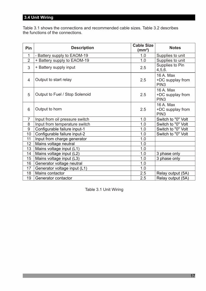
Table 3.1 shows the connections and recommended cable sizes. Table 3.2 describesthe functions of the connections.
+ Battery supply to EAOM-192 1.0 Supplies to unit- Battery supply to EAOM-191 1.0 Supplies to unit
Pin DescriptionCable Size
(mm²)Notes
3 + Battery supply input 2.5Supplies to Pin4,5,6.
Output to start relay4 2.516 A. Max+DC supplay fromPIN3
Output to Fuel / Stop Solenoid5 2.5
Output to horn6 2.5
Input from oil pressure switch7 1.0 Switch to "0" VoltInput from temperature switch8 1.0 Switch to "0" VoltConfigurable failure input-19 1.0 Switch to "0" VoltConfigurable failure input-210 1.0 Switch to "0" VoltInput from charge generator11 1.0Mains voltage neutral12 1.0Mains voltage input (L1)13 1.0Mains voltage input (L2)14 1.0 3 phase onlyMains voltage input (L3)15 1.0 3 phase onlyGenerator voltage neutral16 1.0Generator voltage input (L1)17 1.0Mains contactor18 2.5 Relay output (5A)Generator contactor19 2.5 Relay output (5A)
16 A. Max+DC supplay fromPIN3
16 A. Max+DC supplay fromPIN3
3.4 Unit Wiring
Table 3.1 Unit Wiring

18
Table 3.2 Unit Wiring Description
Pin Function1 Negative battery input supplies EAOM-19.2 Positive battery input supplies EAOM-19.3 Battery positive input. Supplies Pin 4,5 and 6.4 Output to Start relay. +DC supply from pin 3. Controls starter motor.
6 Output to horn. +DC supplies from pin 3. Alarm output.
12 Mains voltage neutral.
16 Generator voltage neutral.
18 Mains contactor. Relay output (NC).19 Generator contactor. Relay output (NO).
5Output to Fuel/Stop solenoid. +DC supply from pin 3. Controls fuel to engine orcontrols engine stopping
8Input from Temperature switch. Switched to 0V, when engine temperature exceedsthermostat setting.
11Input from charge generator. Can be used to detect when engine has started. Must be connected to +BAT if not used.
17Input from generator L1 phase. Unit can be programmed to use frequency of alternator output to detect when engine has started.
7Input from Oil Pressure switch. The oil pressure switch must be the type that openswhen oil pressure is normal, and closes on low oil pressure. (failure condition orengine stopped.)
9Configurable input-1. Normally open. When switched to 0V, sounds the horn andflashes SPARE-1 LED on panel. Can be programmed to stop the engine or de-energise the generator contactor.
10Configurable input-2. Normally open. When switched to 0V, sounds the horn andflashes SPARE-2 LED on panel. Can be programmed to stop the engine or de-energise the generator contactor.
131415
L1L2L3
Mains voltage inputs. Used to detect failure for controlling automatic transfer of load to generator. Pins 14 and 15 not used on single phase applications.
3.5 Unit Wiring Description

4. Definition Of Front Panel And Accessing To The Parameters
19
Number Comment
1
6
7
8
4
9 The LED shows the load isn't connected to the mains. It's colour is red.10 The LED shows the load isn't connected to the generator. It's colour is red.
3
The LED shows the Unit is in TEST position. It's colour is red. The LED light off the unit is in other than TEST position.
In the MANUAL, AUTO and TEST modes the LED (3) lights on when the engine is in the start position. LED' s colour is green.
5The LED shows the load is supplied from the generator. It's colour is green. If this LED is lit that the generator contactor is closed and the load is supplied from the generator.
2The red LED shows the EAOM-19 is in the Programming Mode. The LED is lit when the unit is in the Programming Mode, lit lights off when the unit is in the other modes.
The LED shows the unit is in OFF position. It's colour is red. The LED light off the unit is in other than OFF position.The LED shows the Unit is in AUTO position. It's colour is red. The LED light off the unit is in other than AUTO position.In the MANUAL, AUTO and TEST modes the LED (8) lights on when the engine is stop position. LED' s colours is red.
The LED shows the load is connected to the mains. It's colour is green.
4.1 Front Panel Description
2
109
87
6
111213
17 18 19 20
27
24
25
21 22
3
4
5
161514
1
UV
Hz.
OFF AUTO
TEST
VL31/L3NVL23/L2NVL12/L1N
PROG
TEST RESET
G
G
EAOM - 19
MAN.START
MAN.STOP
~~ ~~~~~~~~~~
RPM
VV
FAILEDTO START
HIGHTEMPERATURE
LOW OILPRESSURE
OVER SPEEDFAILURE
VOLTAGEFAILURE
CHARGINGFAIL
VZBATT. VOLT.FAILURE
SPARE 1
SPARE 2
G
23
26

20
Number Comment
11The button is used for changing operating mode of the unit to the TEST Mode. The unit changes operating mode to the TEST Mode and LED (1) is lit when this button is pressed.
13
14
17
18
19
20
12
The LAMP TEST function of the unit is operated and entered in the Programming Mode by using this button. The LAMP TEST function operates when the button is pressed first. When the button is pressed and keeping pressed for 5 seconds the unit is passed to the PROGRAMMING Mode and LED (2) is lit at the same time.
15 The button is used for transferring the load to the mains only in MANUAL mode.
16The button is used for transferring the load to the generator. It is active only in Manual Mode.
21The button is used for disconnecting the load from the mains. It is only active when the unit is in MANUAL Mode.
22The button is used for disconnecting the load from the generator. It is only active when the unit is in MANUAL Mode.
23Alternate Display Mode Button. It is used for rotating between parameters and approving of the values, of the unit and displays. See section 4 and Section 6.1
24Multi Function Display. It is used for Programming the Unit and features explained in section 6.
25Failure Indicators. Detailed information about this subject is explained in section 6.2.
The button used for starting the engine when the unit is in the MANUAL Mode. The LED (3) is lit when the button is pressed. It is only active when the unit is in MANUAL Mode.
The button is used for changing operating mode of the unit to the OFF Mode. The unit changes operating mode to the OFF Mode and LED (6) is lit when this button is pressed.
The button is used for changing operating mode of the unit to the AUTO Mode. The unit changes operating mode to the AUTO Mode and LED (7) is lit when this button is pressed.
It runs as HORN SILENCE and DECREMENT button. The button, in the normal conditions runs for HORN SILENCE if the horn is running purpose when any failure is detected, it works decreasing values of parameters in PROGRAMMING Mode.
The button is used for stopping the engine when the unit is in the MANUAL Mode. The LED (8) is lit when the button is pressed. It is only active when the unit is in MANUAL Mode.
It runs as INCREMENT and FAILURE RESET button. The button, in the normal conditions runs for FAILURE RESET purpose when any failure is detected, it works increasing values of parameters in PROGRAMMING Mode.
26 Generator voltage okay led.27 Mains voltage okay led.

Press the increment button to access to the parameter value.
P00: Mains Voltage Connection Level
4.2 Accessing To The Operator Parameters
21
Press the increment button.
RESET
PROG
TEST
°F°F
VL12 GEN V.VL23 VL31
RESET
PROG
TEST
°F°F
VL12 GEN V.VL23 VL31
RESET
PROG
TEST
°F°F
VL12 GEN V.VL23 VL31
Operation Screen
Not1: If Enter button is pressed and the operator password is
zero, screen is ignored
and screen is shown.
RESET
PROG
TEST
°F°F
VL12 GEN V.VL23 VL31
RESET
PROG
TEST
°F°F
VL12 GEN V.VL23 VL31
RESET
PROG
TEST
°F°F
VL12 GEN V.VL23 VL31
Programming can be carried out only while the unit is in OFF mode. Press the OFF (17) button. If the engine is running, it will stop and the LED (6) lights on. Then proceed as follows:
Not2: User can access to parameters P00 to P09 and P28 only.
OPERATOR PASSWORD
When the button is pressed for 5 seconds, password is asked for accessing to parameters.
User can access to operator parameters by entering operator or technician password. This selection is done with increment and decrement buttons.
Enter password with increment and decrement buttons.
Press the Enter button to confirm password. If the password is incorrect, the unit will drop out of program mode.
Not3: When screen is shown, parameters can be seen by pressing Enter button without entering operator password. But user can not change the parameters.

22
The value of parameter P00
P01: Mains Voltage Disconnection Level
RESET
PROG
TEST
°F°F
VL12 GEN V.VL23 VL31
RESET
PROG
TEST
°F°F
VL12 GEN V.VL23 VL31
RESET
PROG
TEST
°F°F
VL12 GEN V.VL23 VL31
RESET
PROG
TEST
°F°F
VL12 GEN V.VL23 VL31
RESET
PROG
TEST
°F°F
VL12 GEN V.VL23 VL31
IF NO KEYS ARE PRESSED FOR A PERIOD OF 2 MINUTES, THE UNIT WILL RETURN TO THE NORMAL OPERATION SCREEN.i
Operation Screen
User can access to the following parameter by pressing Enter button.
Change the parameter value with increment and decrement buttons.
Press Enter button to confirm the changed value or access the following parameter.
Press Enter button to confirm the changed value or access the following parameter.
The value of parameter P01
P02: Mains Voltage Upper Limit
Press the increment button to access to the parameter value.
Change the parameter value with increment and decrement buttons.
User can access to the following parameter by pressing Enter button. On this way user can access to parameters P00 to P09 and P28 only.
To exit the programming mode,
press the PROG button.

4.3 Accessing To The Technician Parameters
23
RESET
PROG
TEST
°F°F
VL12 GEN V.VL23 VL31
RESET
PROG
TEST
°F°F
VL12 GEN V.VL23 VL31
RESET
PROG
TEST
°F°F
VL12 GEN V.VL23 VL31
RESET
PROG
TEST
°F°F
VL12 GEN V.VL23 VL31
P00: Mains Voltage Connection Level
RESET
PROG
TEST
°F°F
VL12 GEN V.VL23 VL31
RESET
PROG
TEST
°F°F
VL12 GEN V.VL23 VL31
RESET
PROG
TEST
°F°F
VL12 GEN V.VL23 VL31
Not2: User can access to all parameters (P00 to P29).
TECHNICIAN PASSWORD
When the button is pressed for 5 seconds, password is asked for accessing to parameters.
User can access to technician parameters by entering technician password. This selection is done with increment and decrement buttons.
Press the Enter button.
Press the increment button.
Enter password with increment and decrement buttons.
Not1: If Enter button is pressed and the technician password is
zero, screen is ignored
and screen is shown. Press the Enter button to confirm password. If the password is incorrect, the unit will drop out of program mode.
Not3: When screen is shown, parameters can be seen by pressing Enter button without entering operator password. But user can not change the parameters.
Press the increment button to access to the parameter value.
Operation Screen
Programming can be carried out only while the unit is in OFF mode. Press the OFF (17) button. If the engine is running, it will stop and the LED (6) lights on. Then proceed as follows:

24
The value of parameter P00
P01: Mains Voltage Disconnection Level
RESET
PROG
TEST
°F°F
VL12 GEN V.VL23 VL31
RESET
PROG
TEST
°F°F
VL12 GEN V.VL23 VL31
RESET
PROG
TEST
°F°F
VL12 GEN V.VL23 VL31
RESET
PROG
TEST
°F°F
VL12 GEN V.VL23 VL31
RESET
PROG
TEST
°F°F
VL12 GEN V.VL23 VL31
User can access to the following parameter by pressing Enter button. On this way user can access to all parameters (P00 to P29).
IF NO KEYS ARE PRESSED FOR A PERIOD OF 2 MINUTES, THE UNIT WILL RETURN TO THE NORMAL OPERATION SCREEN.i
Operation Screen
User can access to the following parameter by pressing Enter button.
Change the parameter value with increment and decrement buttons.
Press Enter button to confirm the changed value or access the following parameter.
Press Enter button to confirm the changed value or access the following parameter.
The value of parameter P01
P02: Mains Voltage Upper Limit
Press the increment button to access to the parameter value.
Change the parameter value with increment and decrement buttons.
To exit the programming mode,
press the PROG button.

Prm. No. Definition of Parameter Unit Lower / Upper Limit DefaultP00 Mains voltage connection level VAC 60 - 600 320P01 Mains voltage disconnection level VAC 60 - 600 300P02 Mains voltage upper limit VAC 60 - 600 440P03 Alternator voltage lower limit VAC 60 - 600 320P04 Alternator voltage upper limit VAC 60 - 600 440P05 Hz. 30.0 - 75.0 53.0P06 Number 1 -10 3
P09 Mains transition delay Minute 0 - 30 3P10 Single / Three phase selection Select 1 PH / 3 PH 3 PHP11 Battery voltage lower limit VDC 7.2 - 24.0 8.0
P13 Stop / Fuel solenoid selection StoP / FuEL FuELP14 Stop magnet energising time 0 - 99 20
P16 Starting attempt duration 5 - 99 5
P18 Speed limit for crank disconnection 20.0 - 45.0 40.0P19 Control on delay 0 - 99 10P20 Alternator voltage fault control delay 0.0 - 10.0 5.0P21 Speed fault control delay Second 5.0
P24 Horn output selection 0 - 1 0P25 Choke time 0.8
P15.0P15.1P15.2P15.3
P07
P08
P12
P15
P17
P22
P23
Speed upper limitNumber of starting attempts
Engine cooling time
Horn duration
Mains-Generator or Generator-Mains change over delay
Configurable failure input-2 (Pin10)The same as P22
Configurable failure input-1 (Pin9)
Alternator voltage limit for crank disconnection
Engine started signal
Charge generatorSpeedAlternator voltageOil pressure
0
1
2345
6
LED flashes and horn sounds. It is unlatched.LED flashes and horn sounds and then stays on until reset.As "1" plus engine stops.As "0" but only while engine running.As "1" but only while engine running.As "4" plus engine stops if running.As "4" plus generator contactor de-energised , if engine running.
Minute
Second
Second
SelectSecond
Select
Second
VAC
Hz.SecondSecond
Number
Number
NumberSecond
0 - 999
0 - 990 = disables cooling process
0.1 - 25.0
no / YES
40 - 360
0 - 6
0 - 6
0 = continuous
no / YESno / YESno / YES
0.0 - 10.0
0.0 - 10.0
3
60
1.0
YESNo
YESNo
300
0
0
P26 Generator start delay 0 - 9999 0P27 Oil sensor selection 0
SecondNumber 0 - 1
P28 Operator password (P00 to P09, and P28) 0 - 9999 0P29 Technician password (P00 to P29) 0
NumberNumber 0 - 9999
25
4.4 Parameter List

4.5 Explanation of Parameters
26
P00 Mains voltage connection levelP01 Mains voltage disconnection levelP02 Mains voltage upper limit
In Automatic mode, the unit uses these parameters to decide when to switch the load between the mains supply and the generator. If the mains voltage is higher than the Upper Limit or lower than the Disconnection Level, the unit connects the load to the generator instead of to the mains. If the load is running on the mains and the mains voltage falls, the unit will switch the load to the generator when the mains voltage falls below the Disconnection Level. Conversely, if the mains voltage is low and the load is running on the generator, the unit will not restore the mains supply to the load until the mains voltage reaches the Connection Level. This hysteresis prevents constant switching between mains and generator as the mains varies about the switching levels. Figure 4.1 shows how, in automatic mode, the load is transferred between mains and generator as the mains voltage varies over time.
Figure 4.1 Load Switching Levels
4.5.1 Mains Voltage Connection(P00) and Disconnection Level(P01), Upper Limit(P02)
Defaultlevels
440V
320V
300V
TimeMains
voltage
Upper limit
Mains voltage
Connection level
Disconnection level
Load switchingMains
GeneratorGeneratorMains Mains MainsGen.

27
4.5.2 Alternator Voltage Lower(P03) and Upper Limit(P04), Fault Control Delay(P20)
P03 Alternator voltage lower limitP04 Alternator voltage upper limitP20 Alternator voltage fault control delay
At the end of Contro on delay time defined by parameter P19, a fault will be reported if the generator voltage goes outside the window defined by the upper and lower limits for more than the time defined as the Alternator voltage fault control delay (P20). This failure immediately stops the generating set, without cool-down delay.
P05 Speed upper limitP21 Speed fault control delay
At the end of Contro on delay time defined by parameter P19, a fault will be reported if the generator frequency exceeds the upper limit for more than the time defined as the Speed fault control delay (P21). This failure immediately stops the generating set, without cool-down delay.
4.5.3 Alternator Frequency Upper Limit(P05), Fault Control Delay(P21)
This is the time the generator is to run off-load once the load transfer signal has ceased. This gives the engine time to cool down before shutdown. Parameter P07 Engine cooling time defines the duration of this cooling-off period.
4.5.4 Engine Cooling Time (P07)
In automatic mode, when the mains has been restored after an interruption, the unit will switch the load back from the generator to the mains supply after the delay programmed into P09. This delay allows time for the mains voltage to settle before reconnecting the load.
4.5.5 Mains Transition Delay (P09)
If the battery voltage drops below the defined Battery Voltage Lower Limit, an alarm occurs. It doesn't stop the generating set.
4.5.6 Battery Voltage Lower Limit (P11)
This parameter allows the use of either a Stop solenoid or a Fuel solenoid.
With Fuel Solenoid selected, the fuel solenoid will be energised while the engine is running and de-energised to cut off the fuel and stop the engine. With Stop Solenoid selected, the stop solenoid is normally de-energised and only energised to stop the engine. The solenoid remains energised for the period defined as the Stop Magnet Energising Time (P14).
4.5.7 Stop / Fuel Solenoid Selection (P13)

28
This parameter sets the period for which the Stop solenoid is energised to stop the engine. It applies only where parameter P13 is set to Stop Solenoid.
The EAOM-19 must de-energise the Start solenoid, to disconnect the starter motor, once the engine is running. Conversely, if the engine does not start after the pre-set start time, the unit will turn off the starter motor and start again. Hence, the unit must be able to detect when the engine has started. Four signals are available to provide engine running information, as follows :
0 Charging generator energising coil current. This current should fall to zero once the engine has started.
1 Engine speed, as selected by parameter P18 Speed Limit for Crank Disconnection.
2 Alternator voltage, as selected by parameter P17 Alternator Voltage Limit for Crank Disconnection.
3 Oil pressure the oil pressure switch should open when the oil pressure is sufficient.
Any or all of these signals can be selected for use. It is advisable to select at least two of them preferably 1 Engine speed and either 0 Charging generator or 2 Alternator voltage.
See Section 4.5.10 . If any of the selected signals appears, the unitassumes that the engine has started.
4.5.8 Stop Magnet Energised Time (P14)
4.5.9 Engine Started Signal (P15)
4.5.10 Starting Attemt Duration(P16), Number Of Starting Attempts(P06)
Engine Starting:When the EAOM-19 receives an Engine Start command, it energises the start solenoid to drive the starter motor and energises the Fuel solenoid (if selected see Section 4.5.7 Stop/Fuel Solenoid selection (P13)) to provide fuel for the engine. If the EAOM-19 detects that the engine has started, it de-energises the starter motor. Engine started signals are defined by parameter P15 Engine started signal see Section 4.5.9.
Parameter P16 Starting attempt duration defines the maximum period for which drive will be applied to the starter motor. It makes a new attempt after a delay equal to twice the defined Starting attempt duration.
Parameter P06 Number of starting attempts defines the number of unsuccessful tries that the EAOM-19 will make before abandoning the attempts. If all these attempts fail, EAOM-19
operations are locked out and a Start Failure indication is displayed.( LED is
lit) The unit remains locked until the RESET (13) button has been pressed.

29
The unit can be configured to respond in any of seven different ways to each one of these inputs. A contact closure to 0V on any of these inputs causes the horn to sound for the period programmed by P08 and lights the appropriate indicator on the panel. The EAOM-19 can be programmed to respond in one of seven ways:
0 Indication is unlatched the LED flashes only while the input is 0V. This input has no effect if any other alarm condition is present.
1 Indication is latched. The LED flashes while the horn is sounding and then stays on until the RESET (13) button is pressed.
2 This is the same as 1 but, in addition, the engine is shut down.
Options 3...6 are effective only while the engine is running.
3 Indication is unlatched the LED flashes only while the input is 0V. This input operates only if the engine is running and has no effect if any other alarm condition is present.
4 Indication is latched. The LED flashes while the horn is sounding and then stays on until the RESET (13) button is pressed. This input operates only if the engine is running.
5 As 4 but, in addition, the engine is shut down.
6 As 4 but, in addition, the generator contactor is de-energised to disconnect the load from the generator. The engine is not shut down.
During the initial period after the engine has been started, there can be fluctuations in engine speed and alternator output that could generate spurious fault indications. Parameter P19 defines a period during which any fault indications, except High Temperature, will be ignored by the EAOM-19. Also, in the event of a mains failure, transfer of the load from mains to generator will be delayed until the end of the Control On Delay period. This period begins when the EAOM-19 has detected engine starting and has cut off the drive to the starter motor.
4.5.11 Control On Delay (P19)
4.5.12 Configurable Inputs 1 and 2 (P22 and P23)
4.5.13 Horn Output Selection (P24)
This parameter determine the function of horn output(Pin 6);0: Alarm output, 1: Choke output.
4.5.14 Choke time (P25)
This parameter sets the period for which the choke output is energised.
4.5.15 Generator Start Delay (P26)
In automatic mode, when the mains has been interrupted, the unit will start the generator after the delay programmed into P26. This can be used to prevent nuisance tripping when switching loads etc.

30
4.5.16 Oil Sensor Selection (P27)
This parameter determine the function of oil sensor input(Pin 7);
f it is selected as oil pressure sensor(1), the oil pressure parameter (P15.3) of the engine started signals will be functional.
0: Oil level sensor.1: Oil pressure sensor.
If it is selected as oil level sensor(0), the oil pressure parameter (P15.3) of the engine started signals will not be functional. But i
4.5.17 Operator Password (P28)
Use this option to change the Operator password. This password allows access to program parameters P00 to P09 and P28.
4.5.18 Technician Password (P29)
Use this option to change the Technician password. It allows access to program parameters P00 to P29.
iTo prevent to changing unit program parameters by unauthorised personel don’t allow to the learning operator and technician passwords by the others. In case of this situation, change passwords immediately.

5. Commissioning
31
1. Check that the unit is correctly wired and that the wiring is of a standard and rating compatible with the system.
2. Check that the correct fuses are fitted.
3. Program the unit as detailed in Section 4.
4. Take temporary steps to prevent the engine from starting . (for example, disable the fuel solenoid.)
5. After a visual inspection to ensure it is safe to proceed, connect the battery supply.
6. On the EAOM-19, press the MAN ENGINE START (14) button. At this moment the LED (3) lights on.
7. Check that the engine start sequence commences. The starter motor should run for the programmed period (P16) for the pre-set (P06) number of times.
8. Check that the (Start Failure LED) flashes and the LED (3) lights off.
9. Check the unit will change to the STOP position and the LED (8) lights on.
10. Restore the engine to operational state (reconnect the fuel solenoid).
11. Press the MAN ENGINE START (14) button. The LED (3) will light on.
12. Check the start sequence, as follows:
the starter motor runs
the engine starts
the starter motor disengages once the engine is running.
If not, check that the engine is fully operational (fuel available etc.) and check the wiring and programming of the EAOM-19.
13. Check that the engine runs up to its operating speed. If not and an alarm is present, check that the alarm is valid and then check the input wiring.
14. Press the MAN ENGINE STOP (20) button. At this moment the LED (8) will light on. The engine should stop. Allow time for the engine to come to rest.
5.1 Manual Mode

32
1. Check that the mains is connected to the unit and is present.
2. Check the mains voltage readings on the display.
3. At the EAOM-19, press the AUTO (18) button. The LED (7) on the button should light.
4. Switch off the mains supply to the unit. Check that the generator starts and, after a delay, the load is transferred to the generator.
5. Restore the mains supply to the unit. Check that, after a delay, the load is transferred back to the mains and the generator, after a further delay, shuts down.
1. Check that the mains is connected to the unit.
2. Press the TEST (11) button. At this moment the LED (1) will light on.
3. Check that the generator starts and that the load is still connected to the mains.
4. Switch off the mains supply. Check that the contactors change over to connect the load to the generator. Check also that the Auto (7) LED is lit. The unit changes operating mode to AUTO Mode automatically.
5. Restore the mains supply. Check that the contactors reconnect the load to the mains supply.
6. Check that the generator shuts down with cool-down period.
5.2 Auto Mode
5.3 Test Mode

6.1 Alternate Display Description
6. Operation
33
Four-digit, seven-segment LED display. This multi-function display the selected parameter from the list alongside. Use DISPLAY MODE (23) button to select which parameter is to be displayed, as indicated by the adjacent LEDs. The button selects the parameters in sequence, as follows.
Please note that phase-phase voltage readings are prefixed by 'P' while phase-neutral readings are prefixed by 'n'.
VL12 - Mains voltage L1-L2, prefix PVL12 - Mains voltage L1-N, prefix nVL23 - Mains voltage L2-L3, prefix PVL23 - Mains voltage L2-N, prefix nVL31 - Mains voltage L3-L1, prefix PVL31 - Mains voltage L3-N, prefix nGEN V. - Generator voltageGEN FRG. - Generator frequency (Hz)BATTERY - Battery voltage
The LED will flash if the unit detects an engine stopping error. When the
DISPLAY MODE (23) button is pressed so as to select this option, the display will show the cause of the error indication. This error message is:
StP.E - Stop Error
The LED will be skipped if there isn’t an engine stopping error.
ALARM
ALARM
VL12 GEN V.
GEN FRQ.
BATTERY
ALARM
VL23 VL31

34
Example 1: Using Alternate Display with Single phase selection
VL12 GEN V.
GEN FRQ.
BATTERY
ALARM
VL23 VL31
°F°F
VL12 GEN V.
GEN FRQ.
BATTERY
ALARM
VL23 VL31
°F°F
Press the display mode button.
Mains Voltage L1-N Generator Voltage
VL12 GEN V.
GEN FRQ.
BATTERY
ALARM
VL23 VL31
°F°F
VL12 GEN V.
GEN FRQ.
BATTERY
ALARM
VL23 VL31
°F°F
Generator Frequency (Hz) Battery Voltage
VL12 GEN V.
GEN FRQ.
BATTERY
ALARM
VL23 VL31
°F°F
Error Message
VL12 GEN V.
GEN FRQ.
BATTERY
ALARM
VL23 VL31
°F°F
Mains Voltage L1-N
Press the display mode button again.
Press the display mode button again.
Press the display mode button again.
If engine stopping error is not present when the display mode button is pressed, Error Message screen is skipped.
Press the display mode button again.

35
Example 2: Using Alternate Display with Three phase selection
VL12 GEN V.
GEN FRQ.
BATTERY
ALARM
VL23 VL31
°F°F
VL12 GEN V.
GEN FRQ.
BATTERY
ALARM
VL23 VL31
°F°F
Mains Voltage L1-L2 Mains Voltage L1-N
VL12 GEN V.
GEN FRQ.
BATTERY
ALARM
VL23 VL31
°F°F
VL12 GEN V.
GEN FRQ.
BATTERY
ALARM
VL23 VL31
°F°F
Mains Voltage L2-L3 Mains Voltage L2-N
VL12 GEN V.
GEN FRQ.
BATTERY
ALARM
VL23 VL31
°F°F
VL12 GEN V.
GEN FRQ.
BATTERY
ALARM
VL23 VL31
°F°F
Mains Voltage L3-L1 Mains Voltage L3-N
VL12 GEN V.
GEN FRQ.
BATTERY
ALARM
VL23 VL31
°F°F
VL12 GEN V.
GEN FRQ.
BATTERY
ALARM
VL23 VL31
°F°F
Generator Voltage Generator Frequency (Hz)
VL12 GEN V.
GEN FRQ.
BATTERY
ALARM
VL23 VL31
°F°F
VL12 GEN V.
GEN FRQ.
BATTERY
ALARM
VL23 VL31
°F°F
Battery Voltage Error Message
VL12 GEN V.
GEN FRQ.
BATTERY
ALARM
VL23 VL31
°F°F
Mains Voltage L1-L2
Press the display mode button.
Press the display mode button again.
Press the display mode button again.
Press the display mode button again.
Press the display mode button again.
Press the display mode button again.
Press the display mode button again.
Press the display mode button again.
Press the display mode button again.
Press the display mode button again.If engine stopping error is not present when the display mode button is pressed, Error Message screen is skipped.

6.2 Failure Indicators Description
36
Explanations :
1- (Start Failure LED) : The Unit drives to the starter motor according to
values determined in P06 and P16. But, starting the engine is not possible in this values the unit gives a Start Failure. In this case the LED flashes and the horn is sounded. The unit must be reset by pressing the RESET (13) button before a fresh attempt can be made.
2- (High Temperature Failure LED) : Failure will be active when the High
Temperature Switch is which is connected to the Unit via Pin 8 getting excessive hot as result of possible heating of engine. In this case the LED flashes and the Horn is sounded and engine shuts-down without any cool-down period.
3- (Low Oil Pressure Failure LED) : The sensor that is connected to the
Unit via Pin 7 is Normally Closed. The contact will open when Oil Pressure in the engine reaches to proper level. If the contact will not open the engine is running. In this case the LED flashes and the Horn is sounded and engine shuts-down without any cool-down period.
4- (Over Speed Failure LED) : The unit decides to the Over Speed Failure that
depending on the values of parameters P05 and P21. At the end of control on delay time defined by parameter P19, if the generator speed goes above the Speed Upper Limit and continues for of Speed Fault Control Delay time period, the LED flashes and the Horn is sounded and engine shuts-down without any cool-down period.
Generator speed is measured from alternator output frequency.
5- (Generator voltage Failure LED): The unit decides to the Generator Voltage
Failure when the Alternator Voltage is out of the values determined with P03, P04 and P20 parameters. At the end of control on delay time defined by parameter P19, if the alternator voltage is out of Alternator Voltage Lower Limit or Alternator Voltage Upper Limit and continues for of Alternator Voltage Fault Control Delay time period, the LED flashes and the Horn is sounded and generator contactor is released if closed, engine shuts-down without any cool-down period.
SPEED
Bat.VoltageFailure
SPEED
SPARE 1
SPARE 2

6- (Charge Generator Failure LED): At the end of control on delay time
defined by parameter P19, the unit checks + Voltage which comes from Charge Generator via Pin 11. If there is no Voltage the unit decides to Charge Generator Failure. In this case the LED flashes and the Horn is sounded.
7- (Battery Voltage Failure LED): Battery Voltage Failure is monitored
continues in all modes except "OFF" mode. This failure occurs continuously when the battery voltage falls below the value specified by the Battery voltage lower limit parameter P11. In this case the LED flashes and the Horn is sounded. It is self resetting once the fault has been removed.
The EAOM-19 measures battery voltage at the EAOM-19 terminals. Depending on the size and length of the cable to the battery, this may be somewhat less than the voltage as measured at the battery.
8- (Configurable Failure Input-1 LED): Configurable Failure-1 input works
on value determined in Parameter P22. When the input is active (Pin 9) the unit works according to selection of user.
9- (Configurable Failure Input-2 LED): Configurable Failure-2 input works
on value determined in Parameter P23. When the input is active (Pin 10) the unit works according to selection of user.
Bat.VoltageFailure
SPARE 1
SPARE 2
Once the EAOM-19 has given a shutdown signal to the engine it expects the engine to rest. It monitors the Engine Started Signal sources and if they still indicate engine movement when
30 seconds time period expires, The StPE alarm signal is generated. The LED
will flash continually.
ALARM
StPE - Stop Error Message (Fail to Engine Stopping):
37
VL12 GEN V.
GEN FRQ.
BATTERY
ALARM
VL23 VL31
°F°F

6.3 Mode Transition
38
The mode can be changed at any time. Any changes between Auto, Manual and Test modes will not effect the current state of the generator or load connection.
6.4 Manual Start
1. Press the MAN ENGINE START (14) button on the panel the LED (3) will light on. The engine should start. The sequence is as follows:
! The starter motor runs! The engine starts
Once the engine is running,! Generator will be ready to take the load after "control on delay" time period like as
AUTO mode.! It is not possible supply to load on the generator unless "control on delay" time is
elapsed (The contactor open / close button does not work)
2. Once "control on delay" time is elapsed, press the MAINS CONTACTOR OPEN (21) button to disconnect the load from the mains supply. LED (9) should light. LED (4) should go off.
3. Press the GENERATOR CONTACTOR CLOSE (16) button to connect the load to the generator supply. LED (5) should light. LED (10) should go off.
6.5 Manual Stop
The LED (8) is lit and engine is stopped when the MAN ENGINE STOP (20) button is pressed. When the MAN ENGINE STOP (20) button is pressed while the load connected to the generator first generator contactor is released then engine is stopped after a cool down period.
6.6 Auto Operation
Press the AUTO (18) button to select Auto mode. The LED (7) in the corner of the button will light to indicate this mode has been selected.
In the event of a mains voltage failure, the unit will start up the generator and, once the generator is running and alternator voltage available, will transfer the load to the generator. When the mains is restored and stable, it will transfer the load back to the mains and, after a cool-down period, shut down the generator.
6.7 Test Operation
Press the TEST (11) button to select Test mode the LED (1) will light on. This mode allows for testing of the generator off load. All alarm circuits will operate so that any faults will be reported. If a mains failure occurs while the unit is in Test mode, the unit will revert to Auto mode and will switch the load to the generator.

7 Fault Finding
39
Indicators on the central section of the panel will flash if a fault is detected. See Section 6.2 Failure Indicators Description. Fault conditions except Battery Voltage Failure are latched so that further operation is prevented. If a failure is indicated, proceed as follows:
1. Find and fix the fault.
2. Press the RESET (13) button to enable a restart.
In addition to the indicators on the centre panel, the LED will flash in the event of
an engine stopping error. To display the fault message reported by the LED,
press repeatedly DISPLAY MODE (23) button until the ALARM option has been selected. If there isn't fault message, the ALARM option will be skipped.
ALARM
ALARM
Symptom Possible Remedy
Unit is in operativeCheck the battery and wiring to the unit.Check the DC supply. ( measure voltage between pins 1 and 2 )
Check the DC fuse.Check engine oil level and pressure.Check oil pressure switch and wiring.Check that oil pressure switch is of the normally closed type (opens on oil pressure).Check engine temperature and cooling systems.Check switch and wiring.Check that temperature switch is of normally open type (closes on high temperature).Check fuel solenoid and wiring, fuel and battery. Reset the EAOM-19 and restart the engine.Check for battery + output at pin 5, (Fuel Solenoid if selected)Check the signals that the EAOM-19 is using to determine if the engine has started. Refer to engine manual.Check wiring to starter solenoid.Check battery supply.
Check battery supply is present on the Start output pin 4 of the EAOM-19.
Low oil pressure fault after engine has started.
High engine temperatureFault after engine has started.
Failed to Start fault.Engine failed to start after Pre-set number of Attempts.
Starter motor inoperative.
Tablo 7.1 Fault Finding
Disconnect the equipment totally from electricity in the best and correct way during mechanical and electrical maintenance. When this is not possible, the equipment must be in the "OFF" position for preventing any accident.c

8. Specifications
40
Equipment Use : Electrical control equipment for generating sets
Housing & Mounting : 72mm x 72mm x 95mm. (Including connectors) ¼ DIN43700 plastic housing for panel mounting.
Panel Cut-Out : 69mm x 69mm.
Protection : NEMA 4X (Ip65 at front panel, Ip20 at rear side).
Weight : Approximately 270gr.
Enviromental Rating : Standard, indoor at an altitude of less then 2000 meters with non-condensing humidity.
Operating / StorageTemperature: -25 C to +70 C / -40 C to +85 C.
Operating / Storage Humidity : 90 % max. (non-condensing)
Installation Over Voltage : II Appliances, portable equipment
Category
Pollution Degree : II, Normal office or workplace, non conductive pollution.
Mode Of Operation : Continuous.
DC Battery Voltage Supply : 8 to 32 V Z, max. operating current is 240 mA.
Cranking Dropouts : Battery voltage can be "0" Volt for max. 100 ms during cranking (battery voltage should be at least nominal voltage before cranking).
Battery Voltage Measurement : 8 to 32 V Z, accuracy; 1 % FS, resolution; 0,1 V.
Mains Voltage Measurement : Selectable three phase or single phase, 4 wire connection for three phase, 2 wire connection for single phase gen-set. 35 to 300 V V Ph-N, 15.6 to 99.9 Hz. Accuracy; 1 % FS, Resolution; 1 V.
Generator Voltage : 35 to 300 V V Ph-N, 15.6 to 99.9 Hz.Measurement Accuracy; 1 % FS, Resolution; 1V.
Generator Speed (Frequency) : 15.6 to 99.9 Hz. (min 35 V V Ph-N) Accuracy; 0,25 % FS, Resolution; 0,1 Hz.
Charge Generator Excitation : 220 mA, max 4W.
Contact Sensing Inputs : Oil Pressure Switch (NC) Temperature Switch (NO) Configurable Input-1 (NO) Configurable Input-2 (NO)
Relay Outputs : Start relay (1NO. 16A@32V Z ) Fuel relay (1NO. 16A@32V Z ) Horn relay (1NO. 16A@32V Z ) Mains contactor relay (1NC. 5A@250V V ) Generator contactor relay (1NO. 5A@250V V )

41
Display : 4 digits, 7 segments, LED display showin; Mains voltage (Ph-Ph or Ph-N) Alternator voltage (u only) Alternator frequency Battery voltage Program parameters
Failure Indicators : Start failure LED High temperature LED Low oil pressure LED Over speed LED Generator voltage failure LED Charge generator failure LED Battery voltage failure LED Configurable input-1 LED Configurable input-2 LED
Status Indicators : TEST mode LED PROG mode LED OFF mode LED AUTOMATIC mode LED Man Engine Start LED Man Engine Stop LED Mains contactor open LED Generator contactor open LED Mains contactor close LED Generator contactor close LED Generator voltage okay LED Mains voltage okay LED

9. Block Diagram
42
POWERSUPPLY
RELAYOUTPUTS
BATTERYVOLTAGESENSING
MICROCONTROLLER
ANALOGTO
DIGITALCONVERTOR
COUNTER&
TIMER
MAINS&
GENERATORVOLTAGESENSING
&CONDITIONING
FREQUENCYSENSING
FROMGENERATOR
VOLTAGE
LED DISPLAYS&
INDICATORS
+BATTERY
MAINS L1
GEN. NGEN. L1
MAINS L2MAINS L3
MAINS N
EAOM-19 BLOCK DIAGRAM
FAILURE&
CONTROLINPUTS
PUSHBUTTONS

10. User Defined Parameters
43
Prm. No. Definition of Parameter User Defined ValueP00 Mains voltage connection level
P01 Mains voltage disconnection level
P02 Mains voltage upper limit
P03 Alternator voltage lower limit
P04 Alternator voltage upper limit
P05P06
P24 Horn output selection
P25 Choke time
P07P08
Speed upper limitNumber of starting attemptsEngine cooling time
Horn durationP09 Mains transition delay
P10 Single / Three phase selection
P11 Battery voltage lower limit
P12 Mains-Generator or Generator-Mains change over delay
P18 Speed limit for crank disconnection
P19 Control on delay
P20 Alternator voltage fault control delay
P21 Speed fault control delayP22P23 Spare input-2 (Pin10)
Spare input-1 (Pin9)
P13 Stop / Fuel solenoid selection
P14 Stop magnet energising time
P16 Starting attempt duration
P15.0P15.1P15.2P15.3
P15
P17 Alternator voltage limit for crank disconnection
Engine started signal
Charge generatorSpeedAlternator voltageOil pressure
List - 1
Change Date : . . . . . / . . . . . / . . . . . . .Change Technician Name :
P26 Generator start delayP27 Oil sensor selectionP28 Operator password (P00 to P09, and P28)
P29 Technician password (P00 to P29)


![. 18m) INDEX I-SIO ] TEL : 0955-72-9135 FAX. 0955-72-9179 E … · 2019. 4. 1. · . 18m) INDEX I-SIO_] TEL : 0955-72-9135 FAX. 0955-72-9179 E-mail toshi-keikaku@city. karatsu. saga.](https://static.fdocuments.us/doc/165x107/60c339752adafc0ac37a32f4/18m-index-i-sio-tel-0955-72-9135-fax-0955-72-9179-e-2019-4-1-18m-index.jpg)