S pecial dition aper - jreast.co.jp€¦ · S pecial dition aper ... thus developed a wedge-shaped...
4
35 JR EAST Technical Review-No.22 S pecial edition paper In order to meet the expected severe environment of future maintenance work such as labor shortages due to low birthrates and tendencies of avoiding dirty, dangerous and difficult work, JR East developed TC-type low-maintenance track with the aim of minimizing maintenance needed. Beginning with introduction to the Yamanote Line in 1997, the track has been laid on lines where relatively lightweight trains run. From 2006, areas where it is laid have been expanded to lines on which freight trains run, including the Tokaido Line, and currently it has been laid over more than 230 km. Railways outside Japan, those in developed countries in particular, mainly adopt ballastless tracks such as slab tracks and Rheda 2000 tracks when constructing new lines. JR East’s full- scale introduction of low-maintenance track to existing lines is example rarely seen in the world, demonstrating the high value of that technology. In the 15 years that have passed since its first introduction, it has had an effect of reducing track maintenance cost approx. 70%, and the P value track irregularity index of that track has been improved to approx. 60% of that of ballast tracks. In some specific track conditions such as in sharp curves with less than 300 m radius and on soft roadbed with high groundwater level, however, cases where repair work was needed have occurred. 1) 2) ere is also concern that train load or earthquake load could cause roadbed hollows at the interface to track without ballast floor behind abutments. 3) 4) is article will report the technical challenges of TC-type low-maintenance track in diverse track conditions such as sharp curves, soft roadbed with high groundwater level, and interfaces to structure such as abutments, and it will in introduce countermeasures to those. Basic Structure of TC-type Low-maintenance Track 2 TC-type low-maintenance track is directly fastened track with 400 mm sleeper width and 750 mm rail fastening device intervals, for which ballast is filled and fixed with cement filler (Fig. 1). Introduction 1 Composition of the cement for the cement filler layer (hereinafter, the “filler layer”) varies according to whether or not freight trains operate on that track. Direct seat type or tie place type rail fastening devices are chosen according to the train weight and the lateral force applied there (Fig. 2). Improvement of Rail Fastening Devices for Sharp Curve Sections 3 3.1 Change of Wedge-shaped Insulator With early TC-type low-maintenance track, direct seat type rail fastening devices were used in sections with less than 300 m curve radius, but polyacetal resin (POM) wedge-shape insulators became worn in some sharp curve sections (Fig. 3). It was thought that the insulators became worn due to instantaneous frictional heat by excessive lateral force, so we thus developed a wedge-shaped insulator of nylon 6,6 that has an approx. 100 ºC higher melting point. As a result, we could approximately double antiwear performance, achieving safety improvement and maintenance cost reduction. Development of TC-type Low-maintenance Track Applicable to Diverse Track Conditions • Keywords: TC-type low-maintenance track, Wedge-shaped insulator, Rail fastening clip, Drainage channel, Mud pumping index, Roadbed hollow TC-type low-maintenance track was developed in 1997 for the purpose of reducing track maintenance work, and it is currently laid over a distance of more than 230 km in the greater Tokyo area including the Yamanote Line. As 15 years have passed since that first of track was laid, maintenance reduction effects and improvement of track state have been proved. In some specific track conditions such as in sharp curves and on soft roadbed with high groundwater level, however, there were cases where repair work was needed. In order to make the track able to handle such track conditions, we have improved rail fastening clips and wedge-shaped insulators for sharp curves with less than 300 m radius and, for locations with high groundwater level, established construction standards for appropriate drainage equipment by clarifying the track subsidence characteristics and confirming the effect of drainage. Furthermore, we quantified the effect of roadbed hollows that could occur in roadbed on the interface to structures such as abutments, and based on that, we developed a structure of TC-type low-maintenance track that can be applied to diverse track conditions. * Technical Center, Research and Development Center of JR East Group Yuichiro Hori* Takao Kumakura * Masanobu Kozeki* Large PC sleeper Units: mm Cement filler Ballast Roadbed Direct seat type (mainly for linear sections) Tie plate type (mainly for sharp curves) Fig. 1 Basic Structure Diagram of TC-type Low-maintenance Track Fig. 2 Rail Fastening Devices for TC-type Low-maintenance Track
Transcript of S pecial dition aper - jreast.co.jp€¦ · S pecial dition aper ... thus developed a wedge-shaped...

35JR EAST Technical Review-No.22
Special edition paper
In order to meet the expected severe environment of future maintenance work such as labor shortages due to low birthrates and tendencies of avoiding dirty, dangerous and difficult work, JR East developed TC-type low-maintenance track with the aim of minimizing maintenance needed. Beginning with introduction to the Yamanote Line in 1997, the track has been laid on lines where relatively lightweight trains run. From 2006, areas where it is laid have been expanded to lines on which freight trains run, including the Tokaido Line, and currently it has been laid over more than 230 km.
Railways outside Japan, those in developed countries in particular, mainly adopt ballastless tracks such as slab tracks and Rheda 2000 tracks when constructing new lines. JR East’s full-scale introduction of low-maintenance track to existing lines is example rarely seen in the world, demonstrating the high value of that technology.
In the 15 years that have passed since its first introduction, it has had an effect of reducing track maintenance cost approx. 70%, and the P value track irregularity index of that track has been improved to approx. 60% of that of ballast tracks. In some specific track conditions such as in sharp curves with less than 300 m radius and on soft roadbed with high groundwater level, however, cases where repair work was needed have occurred.1) 2) There is also concern that train load or earthquake load could cause roadbed hollows at the interface to track without ballast floor behind abutments.3) 4)
This article will report the technical challenges of TC-type low-maintenance track in diverse track conditions such as sharp curves, soft roadbed with high groundwater level, and interfaces to structure such as abutments, and it will in introduce countermeasures to those.
Basic Structure of TC-type Low-maintenance Track2
TC-type low-maintenance track is directly fastened track with 400 mm sleeper width and 750 mm rail fastening device intervals, for which ballast is filled and fixed with cement filler (Fig. 1).
Introduction1Composition of the cement for the cement filler layer
(hereinafter, the “filler layer”) varies according to whether or not freight trains operate on that track. Direct seat type or tie place type rail fastening devices are chosen according to the train weight and the lateral force applied there (Fig. 2).
Improvement of Rail Fastening Devices for Sharp Curve Sections3
3.1 Change of Wedge-shaped InsulatorWith early TC-type low-maintenance track, direct seat type rail fastening devices were used in sections with less than 300 m curve radius, but polyacetal resin (POM) wedge-shape insulators became worn in some sharp curve sections (Fig. 3).
It was thought that the insulators became worn due to instantaneous frictional heat by excessive lateral force, so we thus developed a wedge-shaped insulator of nylon 6,6 that has an approx. 100 ºC higher melting point. As a result, we could approximately double antiwear performance, achieving safety improvement and maintenance cost reduction.
Development of TC-type Low-maintenance Track Applicable to Diverse Track Conditions
•Keywords: TC-type low-maintenance track, Wedge-shaped insulator, Rail fastening clip, Drainage channel, Mud pumping index, Roadbed hollow
TC-type low-maintenance track was developed in 1997 for the purpose of reducing track maintenance work, and it is currently laid over a distance of more than 230 km in the greater Tokyo area including the Yamanote Line. As 15 years have passed since that first of track was laid, maintenance reduction effects and improvement of track state have been proved. In some specific track conditions such as in sharp curves and on soft roadbed with high groundwater level, however, there were cases where repair work was needed. In order to make the track able to handle such track conditions, we have improved rail fastening clips and wedge-shaped insulators for sharp curves with less than 300 m radius and, for locations with high groundwater level, established construction standards for appropriate drainage equipment by clarifying the track subsidence characteristics and confirming the effect of drainage. Furthermore, we quantified the effect of roadbed hollows that could occur in roadbed on the interface to structures such as abutments, and based on that, we developed a structure of TC-type low-maintenance track that can be applied to diverse track conditions.
*Technical Center, Research and Development Center of JR East Group
Yuichiro Hori*Takao Kumakura* Masanobu Kozeki*
Large PC sleeper
Units: mmCement �ller
Ballast
Roadbed
Direct seat type (mainly for linear sections) Tie plate type (mainly for sharp curves)
Fig. 1 Basic Structure Diagram of TC-type Low-maintenance Track
Fig. 2 Rail Fastening Devices for TC-type Low-maintenance Track
36 JR EAST Technical Review-No.22
Special edition paper
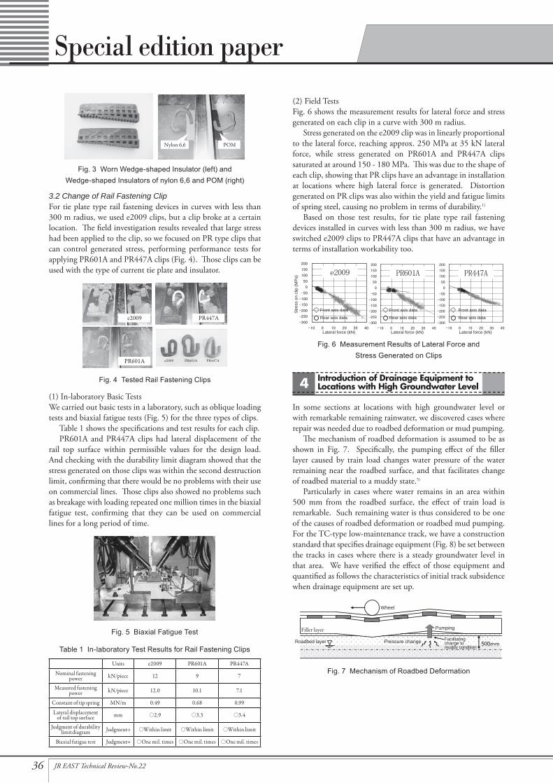
(2) Field TestsFig. 6 shows the measurement results for lateral force and stress generated on each clip in a curve with 300 m radius.
Stress generated on the e2009 clip was in linearly proportional to the lateral force, reaching approx. 250 MPa at 35 kN lateral force, while stress generated on PR601A and PR447A clips saturated at around 150 - 180 MPa. This was due to the shape of each clip, showing that PR clips have an advantage in installation at locations where high lateral force is generated. Distortion generated on PR clips was also within the yield and fatigue limits of spring steel, causing no problem in terms of durability.1)
Based on those test results, for tie plate type rail fastening devices installed in curves with less than 300 m radius, we have switched e2009 clips to PR447A clips that have an advantage in terms of installation workability too.
Introduction of Drainage Equipment to Locations with High Groundwater Level4
In some sections at locations with high groundwater level or with remarkable remaining rainwater, we discovered cases where repair was needed due to roadbed deformation or mud pumping.
The mechanism of roadbed deformation is assumed to be as shown in Fig. 7. Specifically, the pumping effect of the filler layer caused by train load changes water pressure of the water remaining near the roadbed surface, and that facilitates change of roadbed material to a muddy state.5)
Particularly in cases where water remains in an area within 500 mm from the roadbed surface, the effect of train load is remarkable. Such remaining water is thus considered to be one of the causes of roadbed deformation or roadbed mud pumping. For the TC-type low-maintenance track, we have a construction standard that specifies drainage equipment (Fig. 8) be set between the tracks in cases where there is a steady groundwater level in that area. We have verified the effect of those equipment and quantified as follows the characteristics of initial track subsidence when drainage equipment are set up.
3.2 Change of Rail Fastening ClipFor tie plate type rail fastening devices in curves with less than 300 m radius, we used e2009 clips, but a clip broke at a certain location. The field investigation results revealed that large stress had been applied to the clip, so we focused on PR type clips that can control generated stress, performing performance tests for applying PR601A and PR447A clips (Fig. 4). Those clips can be used with the type of current tie plate and insulator.
(1) In-laboratory Basic TestsWe carried out basic tests in a laboratory, such as oblique loading tests and biaxial fatigue tests (Fig. 5) for the three types of clips.
Table 1 shows the specifications and test results for each clip.PR601A and PR447A clips had lateral displacement of the
rail top surface within permissible values for the design load. And checking with the durability limit diagram showed that the stress generated on those clips was within the second destruction limit, confirming that there would be no problems with their use on commercial lines. Those clips also showed no problems such as breakage with loading repeated one million times in the biaxial fatigue test, confirming that they can be used on commercial lines for a long period of time.
Table 1 In-laboratory Test Results for Rail Fastening Clips
Units e2009 PR601A PR447A
Nominal fasteningpower kN/piece 12 9 7
Measured fasteningpower kN/piece 12.0 10.1 7.1
Constant of tip spring MN/m 0.49 0.68 0.99
Lateral displacementof rail top surface mm ○2.9 ○3.3 ○3.4
Judgment of durabilitylimit diagram Judgment→ ○Within limit ○Within limit ○Within limit
Biaxial fatigue test Judgment→ ○One mil. times ○One mil. times ○One mil. times
Nylon 6,6 POM
e2009
PR601A
PR447A
e2009 PR601A PR447A
Stre
ss o
n cl
ip (M
Pa)
Lateral force (kN) Lateral force (kN) Lateral force (kN)
Front axis data
Rear axis data
Front axis data
Rear axis data
Front axis data
Rear axis data
Filler layer
Roadbed layer Pressure change Facilitatingchange tomuddy condition
Pumping
Wheel
Fig. 7 Mechanism of Roadbed Deformation
Fig. 3 Worn Wedge-shaped Insulator (left) andWedge-shaped Insulators of nylon 6,6 and POM (right)
Fig. 6 Measurement Results of Lateral Force andStress Generated on Clips
Fig. 4 Tested Rail Fastening Clips
Fig. 5 Biaxial Fatigue Test

37JR EAST Technical Review-No.22
Special edition paper
4.1 Check of the Effect of Drainage EquipmentAt slope embankments with high groundwater level, we measured groundwater level, rainfall, and track surface height before and after laying TC-type low-maintenance track.
Fig. 9 shows the measurement results for groundwater level and rainfall before and after installation of drainage equipment. Before installation, the groundwater level remained over the border 500 mm below the track surface (hereinafter, the “border”) for a long time even after rainfall ended at 25 mm of total rainfall. After installation, however, the groundwater level returned to lower than the border in around three hours after rainfall ended even at heavy rainfall of 168 mm. We thus confirmed that the drainage equipment could smoothly drain remaining water at the layer higher than the border after rainfall.
4.2 Amount of Initial Track Subsidence Due to Installation of Drainage Equipment
Fig. 10 shows the distribution of the amount of initial track subsidence in relation to the amount of drawdown of steady groundwater level due to installation of drainage equipment.
The average amount of initial track subsidence after installation was 3.2 mm. There was a tendency for greater subsidence the larger the amount of drawdown of the steady groundwater level was. Particularly, when the steady groundwater level is lowered by more than 0.5 m due to installation drainage equipment, the amount of initial track subsidence remarkably increases. In such a case, we believe that we cannot disregard the effect of initial track subsidence on the state of the track.
4.3 Relation between Mud Pumping Index and Initial Track Subsidence
Fig. 11 shows the relation between the mud pumping index5), which indicates the probability of roadbed mud pumping occurring, and the amount of initial track subsidence and number of days until recovery from subsidence.
There is a tendency that the higher the mud pumping index is, the greater the amount of initial track subsidence increases and the longer the period until recovery from subsidence becomes. There is also a singularity where the amount of initial track subsidence is particularly large at a mud pumping index of around 16. This singularity is assumed to be because the amount of drawdown of steady groundwater level exceeds 0.5 m at that mud pumping index due to the installation of drainage equipment.
From this relation, we found that the period until recovery from initial track subsidence is around six months even at locations with a mud pumping index of greater than 40.
Based on those results, we have put together construction standards for laying TC-type low-maintenance track and installing drainage equipment as shown in Fig. 12. Applying these standards enables laying of high-quality TC-type low-maintenance track even if groundwater level is high.
Dis
tanc
e fro
m s
leep
er to
p su
rface
(m)
Rai
nfal
l in
10 m
inut
es (m
m)
Time (h)
Groundwater level (before installing drainage equipment)Groundwater level (after installing drainage equipment)Rainfall (before installing drainage equipment)Rainfall (after installing drainage equipment)
3 hours
Total rainfall of 168 mm(after installing drainage equipment)
Border at 500 mmfrom roadbed surface
Total rainfall of 25 mm(before installing drainage equipment)
Amou
nt o
f ini
tial t
rack
sub
side
nce
(mm
)
Drawdown of steady groundwater level by installing drainage equipment (m)
Average of allmeasurement points 3.2 mm
Amou
nt o
f ini
tial t
rack
sub
side
nce
(mm
)
Perio
d un
til re
cove
ry fr
omin
itial
trac
k su
bsid
ence
(day
s)
Mud pumping index
Amount of initial tracksubsidence (mm)Number of days until recoveryfrom initial track subsidence
180 days(approx. 6 months)
Singularity
Groundwaterlevel higherthan 500 mmbelow roadbedsurface
Install drainage equipment and lay TC-type lowmaintenance track after recovery from initial tracksubsidence (approx. after 6 months).• Particularly when drawdown of steady groundwater level
by installing drainage equipment exceeds 0.5 m.• Particularly when roadbed mud pumping index is high.
Install drainage equipment after laying TC-typelow-maintenance track and adjust rail surfaceif necessary after recovery from initial track subsidence.
Drainagerequired
No drainagerequired
If unavoidable:
Fig. 8 Drainage Equipment (Drainage Channel)
Fig. 9 Results of of Groundwater Level and Rainfall Measurement
Fig. 10 Relation between Drawdown of SteadyGroundwater Level and Initial Track Subsidence
Fig. 11 Mud Pumping Index, Initial Track Subsidence,and Number of Days Until Recovery
Fig. 12 Construction Standards for the Laying TC-TypeLow-maintenance Track and Installing Drainage Equipment

38 JR EAST Technical Review-No.22
Special edition paper
Evaluation of Occurrence of Roadbed Hollows5
Train load or earthquake load causing hollows in the roadbed near the interface to structures such as abutments has been observed, so it is necessary to review safety of train operation in such cases.6) We thus calculated and quantified the distortion of the filler layer and the vertical displacement of rails according to the size of the roadbed hollow based on the results of structural analysis and loading tests.
5.1 Structural Analysis at Roadbed Hollows and Loading Tests
Using the 10 m-long test sample shown in Fig. 13, we carried out structural analysis and loading tests on a full-scale track testing machine to find out distortion of the filler layer and vertical displacement of the rails according to roadbed hollow size. The structural analysis conducted was elastostatic analysis using the Finite Element Method (FEM).
Fig. 14 shows the results of analysis and measurement of maximum distortion generated in the filler layer, and Fig. 15 those of rail vertical displacement. The loading test results exceeded the assumed permissible distortion of the filler layer (92 μ) at a hollow length of around 1.5 m, while the results were almost as analyzed with a hollow length up to 1.5 m. On the other hand, if the hollow length was longer than 1.5 m, distortion exceeded the permissible limit of the filler layer and cracking occurred at
the bottom of the layer. This is believed to be the reason why distortion of the filler layer and rail displacement remarkably increased in loading tests.
5.2 Evaluation of Train Running Safety at Roadbed Hollows If a roadbed hollow occurred under TC-type low-maintenance track, distortion generated in the filler layer remained less than the permissible limit with a hollow length of up to around 1.5 m, but cracks may occur in the filler layer with longer hollows. Rail vertical displacement remarkably increased remarkably in that case, but it remained around 4 mm even with a 2 m-long hollow and cracking in the filler layer. Such small displacement would not immediately affect train running safety.
Conclusion6(1) For the direct seat type rail fastening device installed to track
in sharp curves, we developed a wedge-shaped insulator of nylon 6,6, doubling the antiwear performance of the device.
(2) For the tie plate type rail fastening device installed to track in sharp curves, we adopted PR447A clips to reduce the stress generated, preventing breakage of clips.
(3) We proved that initial track subsidence of an average of 3.2 mm occurs by installing drainage equipment, but it would be recovered from in around six months. Accordingly, we developed construction standards for laying TC-type low-maintenance track and installing drainage equipment.
(4) If a roadbed hollow occurs, cracking may occur in the filler layer with a hollow longer than 1.5 m. But rail vertical displacement would be around 4 mm even with a 2 m-long hollow, not immediately affecting train running safety.TC-type low-maintenance track has maintenance reduction
effects as well as high seismic resistance and buckling strength, contributing to an improvement of safety. We are thus now expanding the range in which that track is applied, including when using continuous welded rail in curve sections of less than 300 m radius.
Reference:1) Takao Kumakura, Toshiyuki Konishi, Koichi Nomoto, Osamu
Wakatsuki, “Shoryokuka Kido ni Tekiyo suru Sen-bane-kei Rail Teiketsu Sochi ni kansuru Kosatsu [in Japanese],” Journal of Railway Mechanics, No. 14, Japan Society of Civil Mechanics (July 2010): 1 - 6
2) Takao Kumakura, Hideaki Ishii, Yuichiro Hori, “Kisetsu Sendo Roban-jo Shoryokuka Kido ni okeru Haisui Setsubi to Kido Henjo no Hyoka [in Japanese],” Proceedings of the 66th JSCE Annual Meeting, IV-074, Japan Society of Civil Mechanics (September 2011): 147 - 148
3) Takao Kumakura, Yuichiro Hori, Masanobu Kozeki, “Studies on Improvement of TC-type Low-maintenance Track,” Railway Engineering 2011, Japan Railway Engineers’ Association (June 2011)
4) Yasuhiro Hagio, Takao Kumakura, Takashi Kashima, “Higashi-nihon Dai-shinsai ni okeru Yamanote Sen Shoryokuka Kido no Higai Hokoku [in Japanese],” Proceedings of the 66th JSCE Annual Meeting, I-414, Japan Society of Civil Mechanics (September 2011): 827 - 828
5) Katsumi Muramoto, Etsuo Sekine, Masaru Otsuka, “Dominant Factors of Degradation of Cohesive-Soil Roadbed under Ballastless Tracks,” RTRI Report, Vol. 18, No. 3, Railway Technology Research Institute (March 2004): 23 - 28
6) Takao Kumakura, Yuichiro Hori, “Roban Kudo Hassei-ji ni okeru Kisetsu Sendo Roban Shoryokuka Kido no Hyoka [in Japanese],” Proceedings of the 18th Jointed Railway Technology Symposium (J-Rail 2011) (December 2011): 99 - 100
Displacement gauge Loading on both rails
Built-in strain gauge
Lengthof hollow
Increase size of hollow
Max
imum
dis
torti
on o
f fille
r lay
er (xμ)
Length of hollow (m)
Loading test result
Analysis result
Assumed permissible distortion: 92μ
Rai
l ver
tical
dis
plac
emen
t (m
m)
Length of hollow (m)
Loading test result
Analysis result
Fig. 15 Analysis and Measurement Resultsfor Rail Vertical Displacement
Fig. 13 Test Sample of 10 m-long Full-size Test Track
Fig. 14 Analysis and Measurement Resultsfor Distortion Generated in Filler Layer