
S- Parameters and Impedance · PDF fileVoltage and current ratio in transmission line set by...
38
M.H. Perrott High Speed Communication Circuits and Systems Lecture 3 S-Parameters and Impedance Transformers Michael H. Perrott February 9, 2004 Copyright © 2004 by Michael H. Perrott All rights reserved. 1
Transcript of S- Parameters and Impedance · PDF fileVoltage and current ratio in transmission line set by...
M.H. Perrott
High Speed Communication Circuits and SystemsLecture 3
S-Parameters and Impedance Transformers
Michael H. PerrottFebruary 9, 2004
Copyright © 2004 by Michael H. PerrottAll rights reserved.
1
M.H. PerrottM.H. Perrott
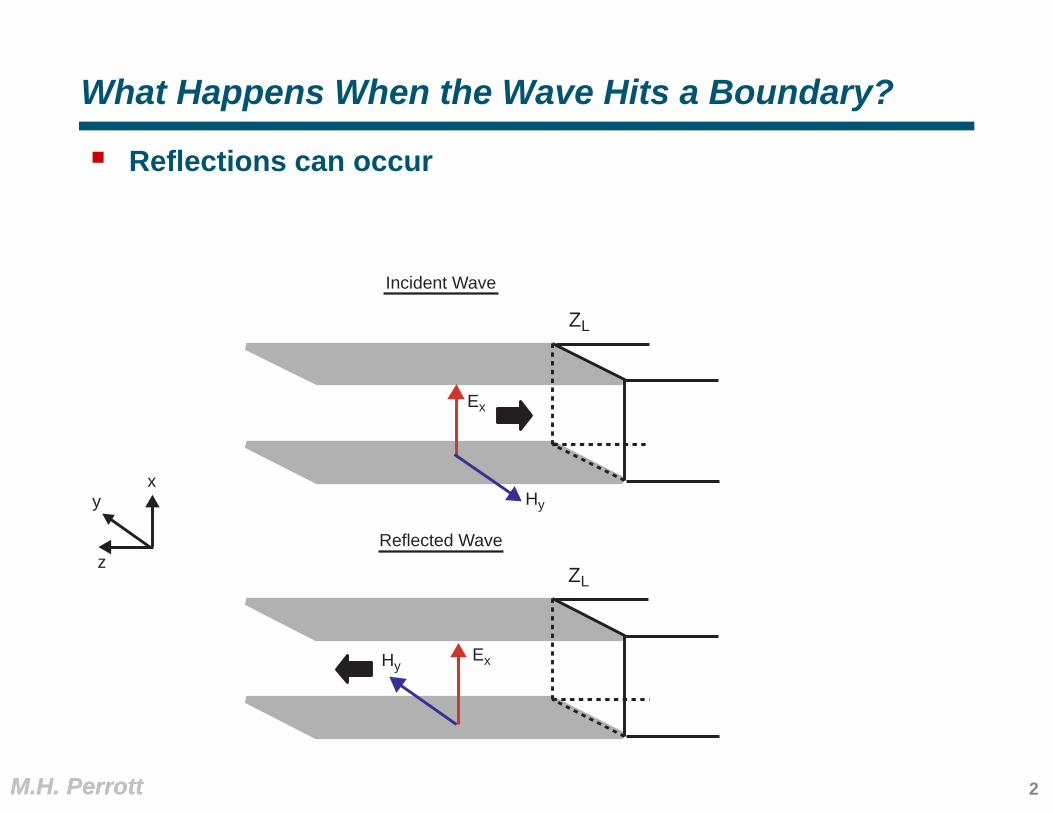
What Happens When the Wave Hits a Boundary?
Reflections can occur
x
z
Ex
Hyy
ZL
ExHy
ZL
Incident Wave
Reflected Wave
2
M.H. PerrottM.H. Perrott
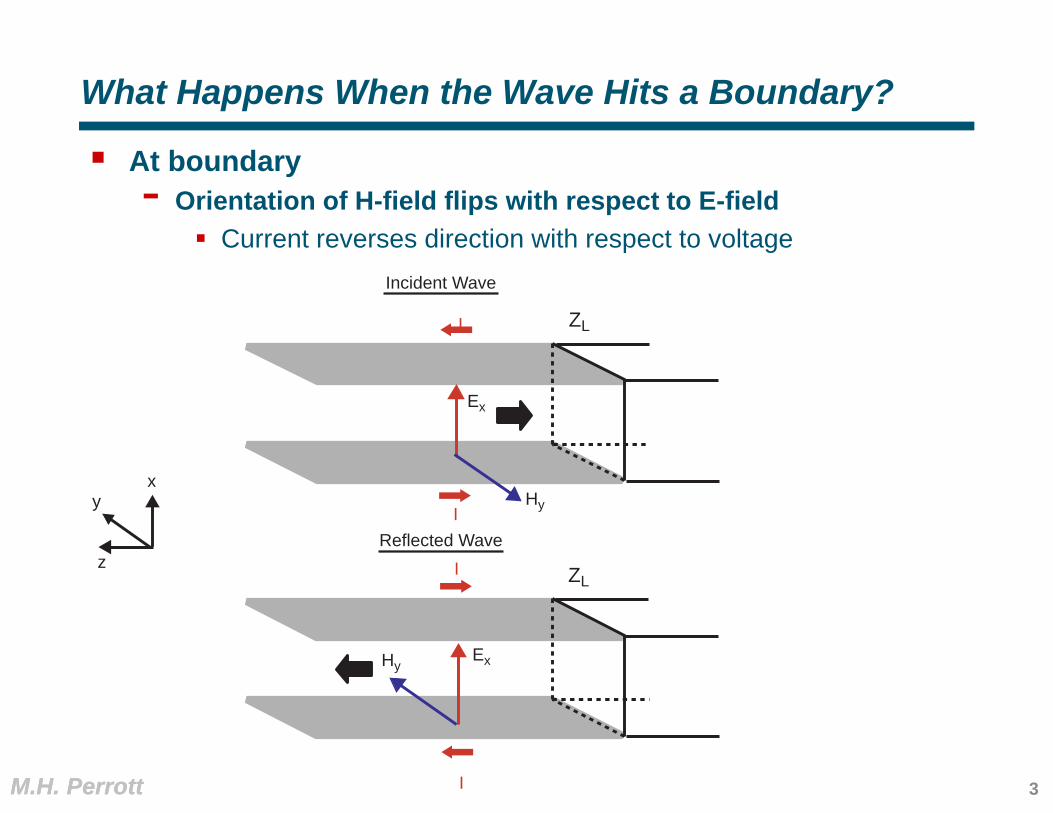
What Happens When the Wave Hits a Boundary?
At boundary- Orientation of H-field flips with respect to E-field
Current reverses direction with respect to voltage
x
z
Ex
Hyy
ZL
ExHy
ZL
Incident Wave
Reflected WaveI
II
I
3
M.H. PerrottM.H. Perrott
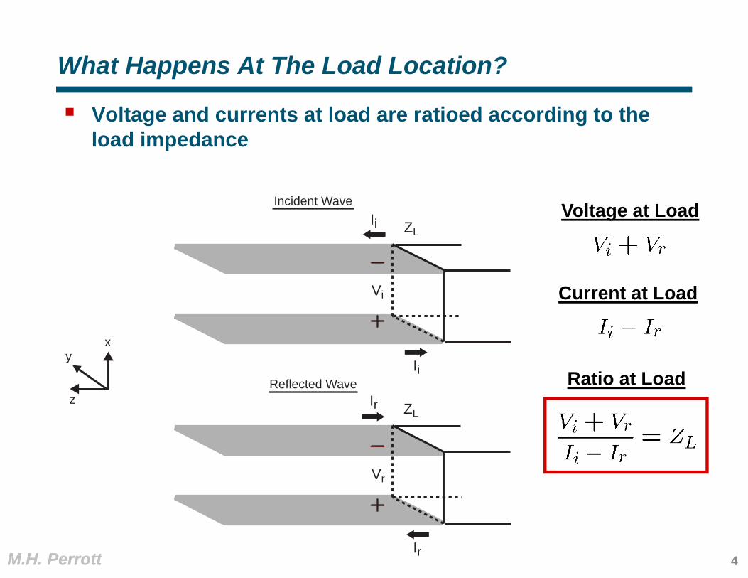
What Happens At The Load Location?
Voltage and currents at load are ratioed according to the load impedance
x
z
y
ZL
ZL
Incident Wave
Reflected Wave
Ii
Ii
Ir
Ir
Vi
Vr
Voltage at Load
Current at Load
Ratio at Load
4
M.H. PerrottM.H. Perrott
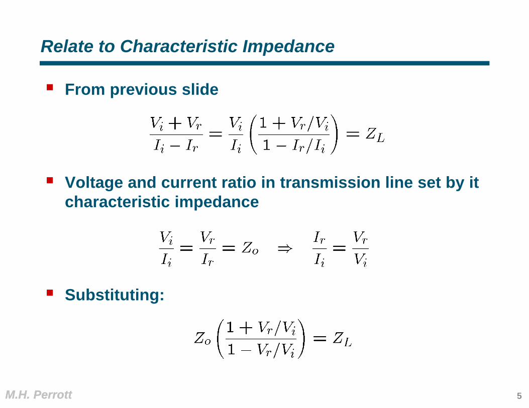
Relate to Characteristic Impedance
From previous slide
Voltage and current ratio in transmission line set by it characteristic impedance
Substituting:
5
M.H. PerrottM.H. Perrott
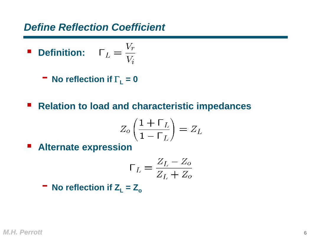
Define Reflection Coefficient
Definition:
- No reflection if L = 0
Relation to load and characteristic impedances
Alternate expression
- No reflection if ZL = Zo
6

M.H. PerrottM.H. Perrott
Parameterization of High Speed Circuits/Passives
Circuits or passive structures are often connected to transmission lines at high frequencies- How do you describe their behavior?
Linear Network
Transmission Line 1 Transmission Line 2
7
M.H. PerrottM.H. Perrott
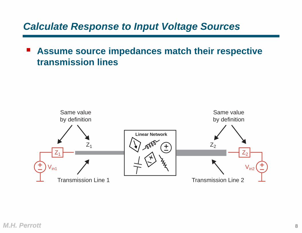
Calculate Response to Input Voltage Sources
Assume source impedances match their respective transmission lines
Z2Z1
Linear Network
Transmission Line 1 Transmission Line 2
Z1
Vin1 Vin2
Z2
Same valueby definition
Same valueby definition
8
M.H. PerrottM.H. Perrott
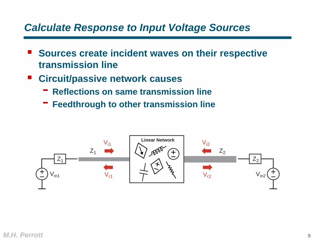
Calculate Response to Input Voltage Sources
Sources create incident waves on their respective transmission line
Circuit/passive network causes - Reflections on same transmission line- Feedthrough to other transmission line
Z2Z1
Linear Network
Z1
Vin1 Vin2
Z2
Vi1
Vr1 Vr2
Vi2
9
M.H. PerrottM.H. Perrott
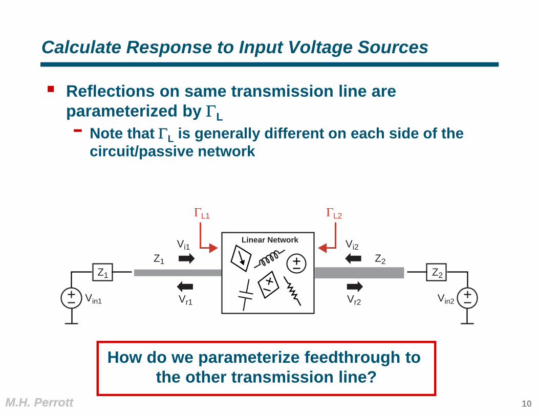
Calculate Response to Input Voltage Sources
Reflections on same transmission line are parameterized by L- Note that L is generally different on each side of the
circuit/passive network
How do we parameterize feedthrough to the other transmission line?
Z2Z1
Linear Network
Z1
Vin1 Vin2
Z2
Vi1
Vr1 Vr2
Vi2
ΓL1 ΓL2
10
M.H. PerrottM.H. Perrott
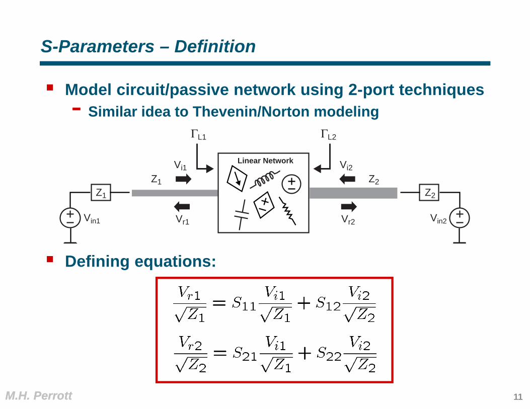
S-Parameters – Definition
Model circuit/passive network using 2-port techniques- Similar idea to Thevenin/Norton modeling
Defining equations:
Z2Z1
Linear Network
Z1
Vin1 Vin2
Z2
Vi1
Vr1 Vr2
Vi2
ΓL1 ΓL2
11
M.H. PerrottM.H. Perrott
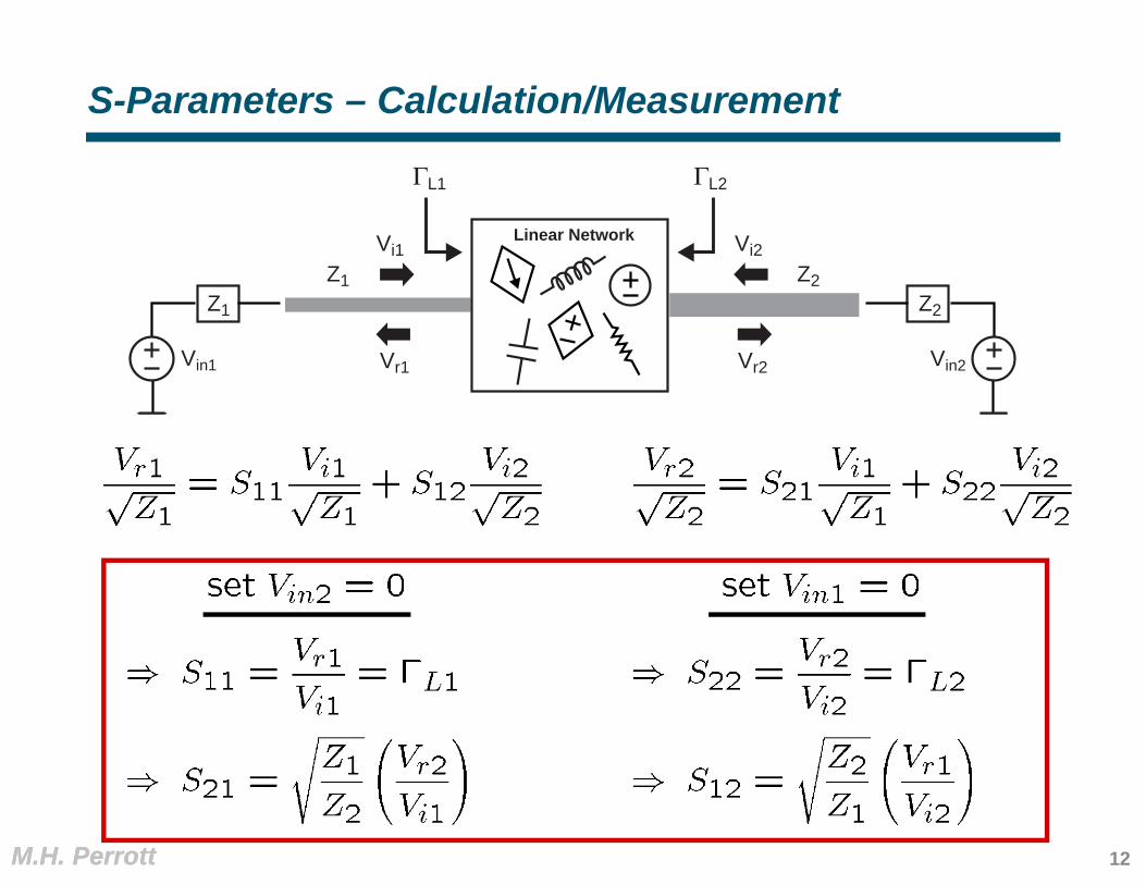
S-Parameters – Calculation/Measurement
Z2Z1
Linear Network
Z1
Vin1 Vin2
Z2
Vi1
Vr1 Vr2
Vi2
ΓL1 ΓL2
12

M.H. PerrottM.H. Perrott
Note: Alternate Form for S21 and S12
Z2Z1
Linear Network
Z1
Vin1 Vin2
Z2
Vi1
Vr1 Vr2
Vi2
ΓL1 ΓL2
13

M.H. PerrottM.H. Perrott
Block Diagram of S-Parameter 2-Port Model
Key issue – two-port is parameterized with respect to the left and right side load impedances (Z1 and Z2)- Need to recalculate S11, S21, etc. if Z1 or Z2 changes- Typical assumption is that Z1 = Z2 = 50 Ohms
Z2Z1
Vi1
Vr1 Vr2
Vi2
S11 S22
S21Z2Z1
S12Z1Z2
S-Parameter Two-Port Model
14
M.H. PerrottM.H. Perrott
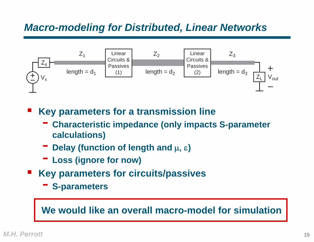
Macro-modeling for Distributed, Linear Networks
Z3Z1Zs
Vs ZL
LinearCircuits &Passives
(1)
Z2 LinearCircuits &Passives
(2)length = d1 length = d2 length = d3 Vout
Key parameters for a transmission line- Characteristic impedance (only impacts S-parameter
calculations)- Delay (function of length and )- Loss (ignore for now)
Key parameters for circuits/passives- S-parameters
We would like an overall macro-model for simulation
15

M.H. PerrottM.H. Perrott
Macro-modeling for Distributed, Linear Networks
Z3Z1Zs
Vs ZL
LinearCircuits &Passives
(1)
Z2 LinearCircuits &Passives
(2)length = d1 length = d2 length = d3
delay1 = velocity
d1
LCd1=
με d1=
delay2 = με d2 delay3 = με d3
Vout
Model transmission line as a delay element- If lossy, could also add an attenuation factor (which is a
function of its length) Model circuits/passives with S-parameter 2-ports Model source and load with custom blocks
16

M.H. PerrottM.H. Perrott
Macro-modeling for Distributed, Linear Networks
Z3Z1Zs
Vs ZL
LinearCircuits &Passives
(1)
Z2 LinearCircuits &Passives
(2)length = d1 length = d2 length = d3
delay1 = velocity
d1
LCd1=
με d1=
delay2 = με d2 delay3 = με d3
ZL=Z1
Vi1
Vr1 Vi2
Vr2
Z1
Z1+Zs
Vs
Zs+Z1
Zs-Z1
delay1
delay1
ZR=Z2
S-param.2-port
(1)
ZL=Z2
Vi1
Vr1 Vi2
Vr2delay2
delay2
ZR=Z3
S-param.2-port
(2)
delay3
delay3
ZL+Z3
ZL-Z3
Vout
Vout
17

M.H. PerrottM.H. Perrott
Note for CppSim Simulations
CppSim does block-by-block computation- Feedback introduces artificial delays in simulation
Prevent artificial delays by- Ordering blocks according to input-to-output signal flow- Creating an additional signal in CppSim modules to
pass previous sample values- Note: both are already done for you in Homework #1
ZL=Z1
Vi1
Vr1 Vi2
Vr2
Z1
Z1+Zs
Vs
Zs+Z1
Zs-Z1
delay1
delay1
ZR=Z2
S-param.2-port
(1)
ZL=Z2
Vi1
Vr1 Vi2
Vr2delay2
delay2
ZR=Z3
S-param.2-port
(2)
delay3
delay3
ZL+Z3
ZL-Z3
Vout
18

M.H. PerrottM.H. Perrott
S-Parameter Calculations – Example 1
Set Vi2 = 0
Z1 Z2
TransmissionLine Junction
Derive S-Parameter 2-Port
Vi1
Vr1 Vr2
Vi2
Set Vi1 = 0
19
M.H. PerrottM.H. Perrott
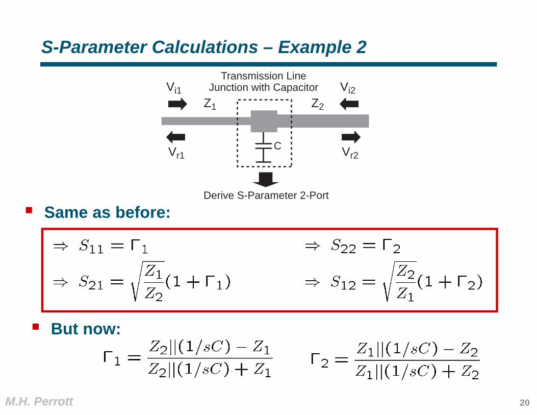
S-Parameter Calculations – Example 2
Same as before:
Z1 Z2
Transmission LineJunction with Capacitor
Derive S-Parameter 2-Port
C
Vi1
Vr1 Vr2
Vi2
But now:
20
M.H. PerrottM.H. Perrott
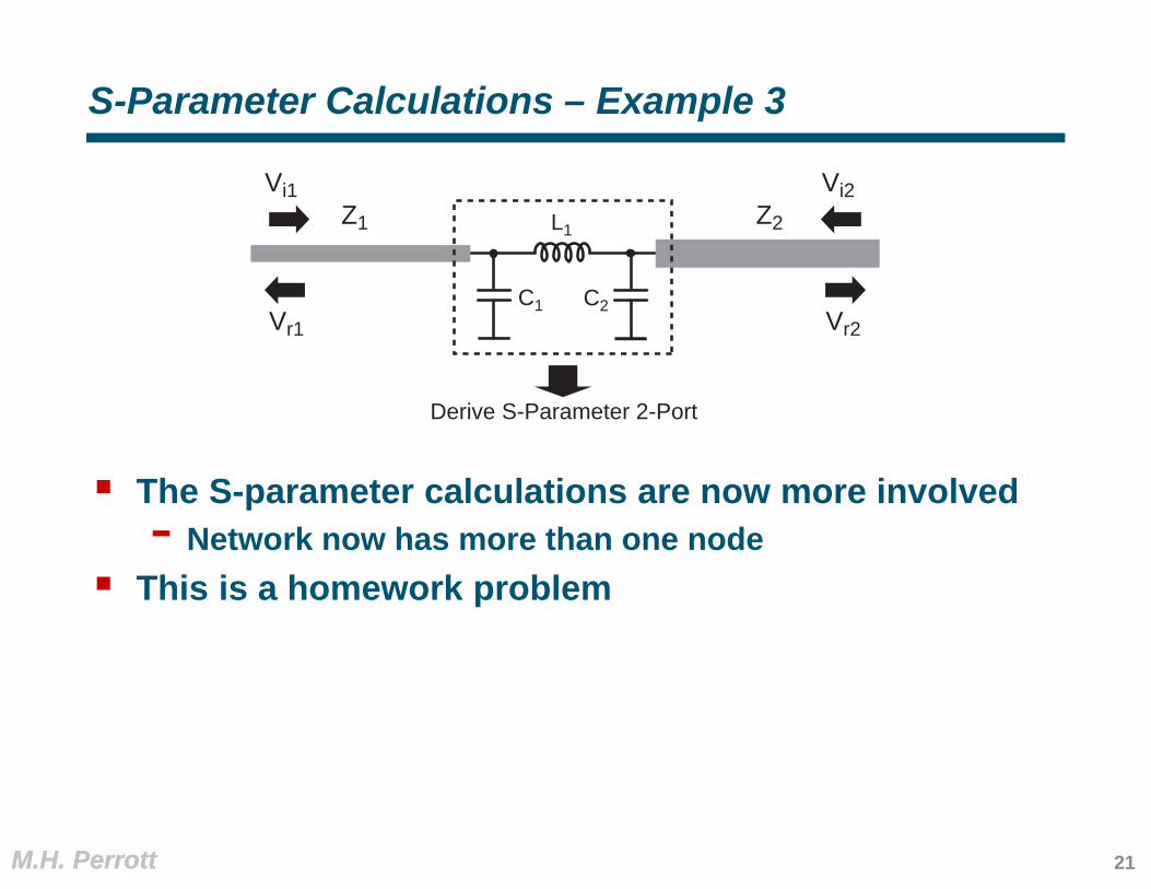
S-Parameter Calculations – Example 3
The S-parameter calculations are now more involved- Network now has more than one node
This is a homework problem
Z1 Z2
Derive S-Parameter 2-Port
Vi1
Vr1 Vr2
Vi2
C1
L1
C2
21

M.H. Perrott
Impedance Transformers
22

M.H. PerrottM.H. Perrott
Matching for Voltage versus Power Transfer
Consider the voltage divider network
For maximum voltage transfer
For maximum power transfer
Vs
RS
RL
I
Vout
Which one do we want?
23

M.H. PerrottM.H. Perrott
Note: Maximum Power Transfer Derivation
Formulation
Take the derivative and set it to zero
Vs
RS
RL
I
Vout
24

M.H. PerrottM.H. Perrott
Voltage Versus Power
For most communication circuits, voltage (or current) is the key signal for detection- Phase information is important- Power is ambiguous with respect to phase information
Example:
For high speed circuits with transmission lines, achieving maximum power transfer is important- Maximum power transfer coincides with having zero
reflections (i.e., L = 0)
Can we ever win on both issues?
Voltage Power
25
M.H. PerrottM.H. Perrott
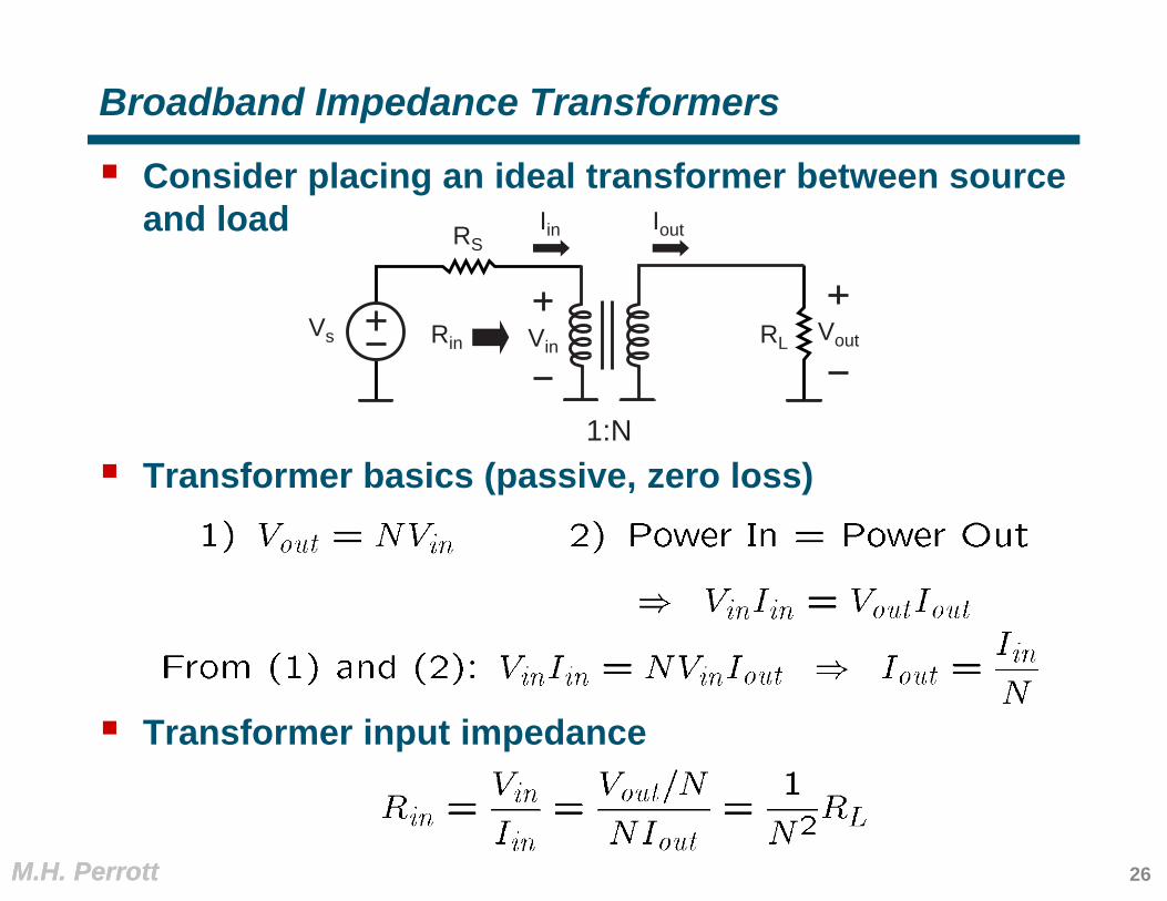
Broadband Impedance Transformers
Consider placing an ideal transformer between source and load
Transformer basics (passive, zero loss)
Transformer input impedance
Vs
RS
RL Vout
Iin Iout
Rin Vin
1:N
26
M.H. PerrottM.H. Perrott
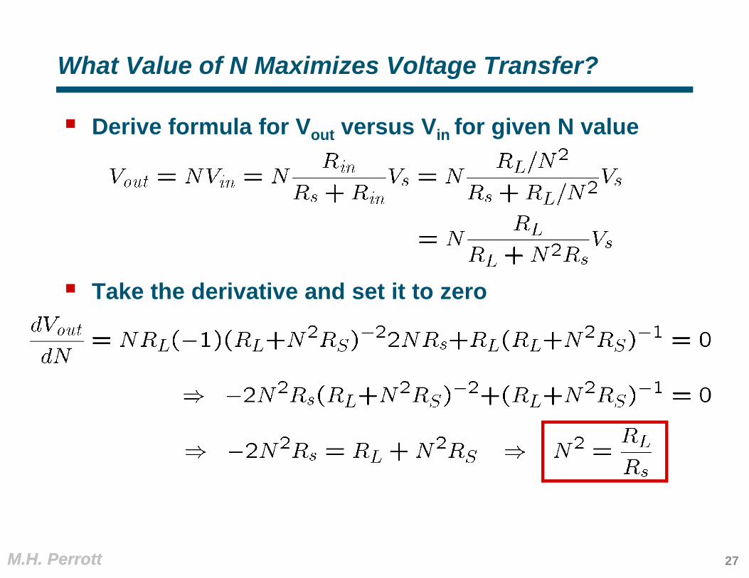
What Value of N Maximizes Voltage Transfer?
Derive formula for Vout versus Vin for given N value
Take the derivative and set it to zero
27

M.H. PerrottM.H. Perrott
What is the Input Impedance for Max Voltage Transfer?
We know from basic transformer theory that input impedance into transformer is
We just learned that, to maximize voltage transfer, we must set the transformer turns ratio to
Put them together
So, N should be set for max power transfer into transformerto achieve the maximum voltage transfer at the load!
28

M.H. PerrottM.H. Perrott
Benefit of Impedance Matching with Transformers
Transformers allow maximum voltage and power transfer relationship to coincide
Turns ratio for max power/voltage transfer
Resulting voltage gain (can exceed one!)
Vs
RS
RL Vout
Iin Iout
Rin Vin
1:N
29
M.H. PerrottM.H. Perrott
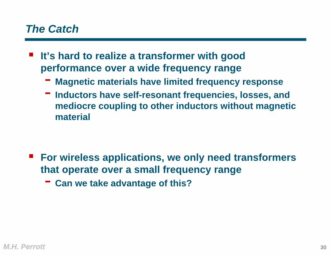
The Catch
It’s hard to realize a transformer with good performance over a wide frequency range- Magnetic materials have limited frequency response- Inductors have self-resonant frequencies, losses, and
mediocre coupling to other inductors without magnetic material
For wireless applications, we only need transformers that operate over a small frequency range- Can we take advantage of this?
30
M.H. PerrottM.H. Perrott
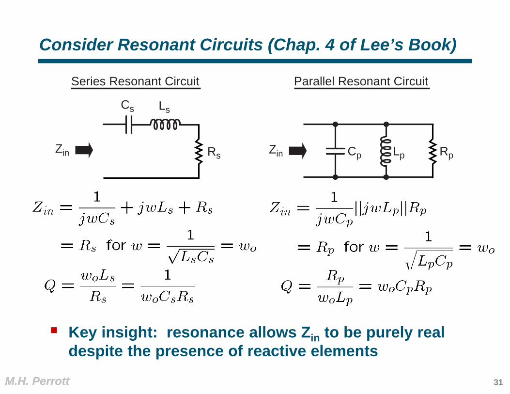
Consider Resonant Circuits (Chap. 4 of Lee’s Book)
Key insight: resonance allows Zin to be purely real despite the presence of reactive elements
Zin RpZin LpCpRs
LsCs
Parallel Resonant CircuitSeries Resonant Circuit
31

M.H. PerrottM.H. Perrott
Comparison of Series and Parallel RL Circuits
Equate real and imaginary parts of the left and right expressions (so that Zin is the same for both)- Also equate Q values
Zin RpZin LpRs
Ls
Parallel RL CircuitSeries RL Circuit
32

M.H. PerrottM.H. Perrott
Comparison of Series and Parallel RC Circuits
Equate real and imaginary parts of the left and right expressions (so that Zin is the same for both)- Also equate Q values
Zin RpZin CpRs
Cs
Parallel RC CircuitSeries RC Circuit
33

M.H. PerrottM.H. Perrott
A Narrowband Transformer: The L Match
Assume Q >> 1
So, at resonance
Transformer steps up impedance!
Zin RpZin LpCRs
Ls
C
Series to ParallelTransformation
34

M.H. PerrottM.H. Perrott
Alternate Implementation of L Match
Assume Q >> 1
So, at resonance
Transformer steps down impedance!
Zin RpZin
L
Cp Rs
L CsParallel to SeriesTransformation
35
M.H. PerrottM.H. Perrott
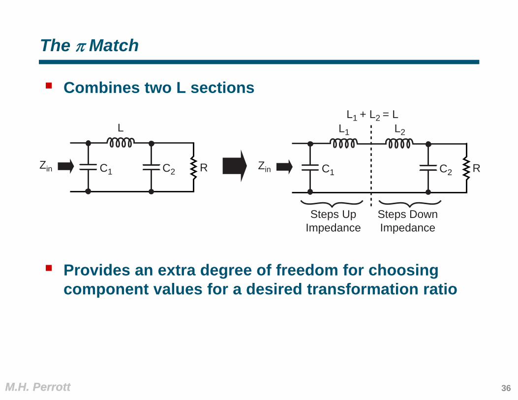
The Match
Combines two L sections
Provides an extra degree of freedom for choosing component values for a desired transformation ratio
Zin R
L
C1 C2 Zin RC1 C2
L1 L2
L1 + L2 = L
Steps UpImpedance
Steps DownImpedance
36
M.H. PerrottM.H. Perrott
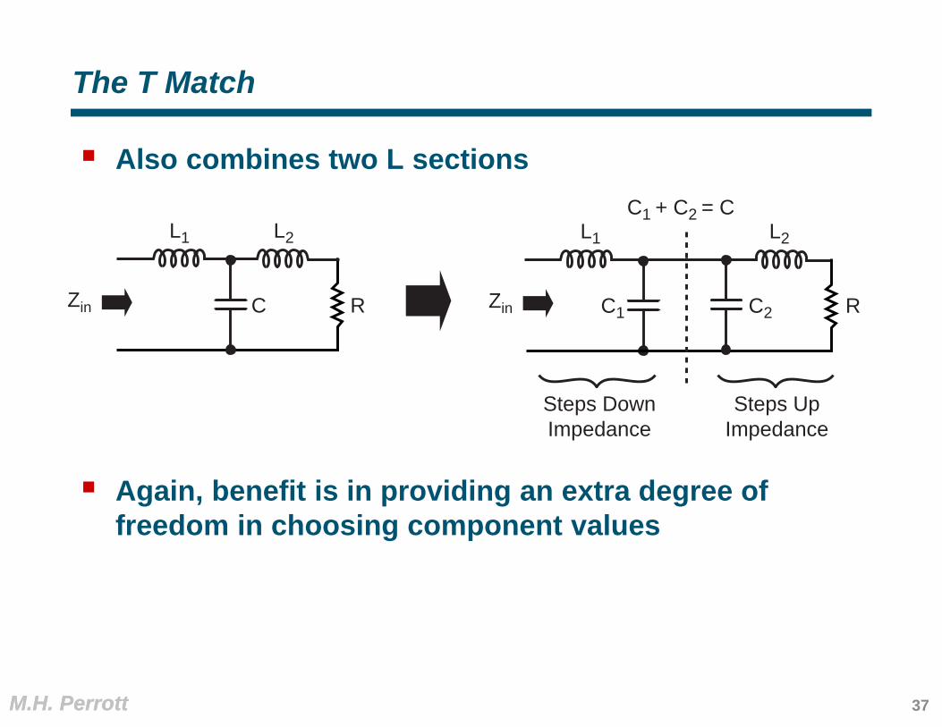
The T Match
Also combines two L sections
Again, benefit is in providing an extra degree of freedom in choosing component values
Zin C2Zin RC
L1 L2
C1 + C2 = C
Steps DownImpedance
Steps UpImpedance
L2L1
C1R
37

M.H. PerrottM.H. Perrott
Tapped Capacitor as a Transformer
To first order:
Useful in VCO design See Chapter 4 of Tom Lee’s book for analysis
Zin L
C2
C1
RL
38


