S. Himmelstein and Company Installation and Operation ... · Torque Limits These settings must be...
32
S. Himmelstein and Company Installation and Operation Manual, Revision E © 2017 S. Himmelstein and Company—all rights reserved www.himmelstein.com INSTALLATION AND OPERATION MANUAL BEARINGLESS DIGITAL TORQUEMETERS APPLIES TO MCRT ® 81008V, MCRT ® 84000V, MCRT ® 85000V, MCRT ® 86000V AND MCRT ® 87000V SINGLE RANGE SERIES PLUS MCRT ® 81708V, MCRT ® 84700V AND MCRT ® 88700V DUAL RANGE SERIES REVISION E Customer: Model Number: Serial Number: Factory Reference Number: Rated Torque (lbf-in): Low Range Torque Rating if MCRT ® 81708V/84700V/88700V (lbf-in): Torque Overload Capacity (lbf-in): Maximum Speed (rpm): Performance Code: Optical Speed Pickup (Code O): ( ) Yes ( ) No Pulses/rev Magnetic Speed Pickup (Code Z): ( ) Yes ( ) No Pulses/rev Special Features: Torquemeter Settings (FIS indicates Factory Installed Setting) Torque Range [FIS = Torquemeter Full Scale]: Digital Torque Output Unit of Measure [FIS = lbf-in]: Digital Temperature Output Unit of Measure [FIS = °F]: Torque Data Filter Cutoff Frequency (Hz) [FIS = 10 Hz]: Torque Limits These settings must be made by user in BLT-WIN PC Interface Software Torque Full Scale Analog Output (volts) MCRT ® 81008V/84000V/86000V and MCRT ® 81708V/84700V/88700V High Range [FIS = ±10 volts]: MCRT ® 85000V/87000V and MCRT ® 81708V/84700V/88700V Low Range [FIS = ±5 volts]: Torque FM Output Center Frequency (kHz) [FIS = 10 kHz]: Torque FM Output Frequency Deviation (kHz) [FIS = ±5 kHz]: PC to Com Port Cable Supplied: ( ) RS232 ( ) RS422 ( ) RS485 PC to Com Port Cable Length [Feet]: Password Protection [FIS = Off] : ( ) On ( ) Off Calibration Data is listed in the attached Calibration Certificate. Calibration data is automatically loaded on power up. Calibration data can also be accessed using a PC and the supplied software. S. Himmelstein and Company Designing and Making the World’s Best Torque Instruments since 1960 2490 Pembroke Avenue, Hoffman Estates, IL 60169 USA • Tel: 847-843-3300 • Fax: 847-843-8488 • www.himmelstein.com
Transcript of S. Himmelstein and Company Installation and Operation ... · Torque Limits These settings must be...

S. Himmelstein and Company Installation and Operation Manual, Revision E
© 2017 S. Himmelstein and Company—all rights reserved www.himmelstein.com
INSTALLATION AND OPERATION MANUAL BEARINGLESS DIGITAL TORQUEMETERSAPPLIES TO
MCRT® 81008V, MCRT® 84000V, MCRT®85000V, MCRT® 86000V AND MCRT® 87000V SINGLE RANGE SERIES
PLUS
MCRT® 81708V, MCRT® 84700V AND MCRT® 88700V DUAL RANGE SERIESREVISION E
Customer:
Model Number: Serial Number:
Factory Reference Number:
Rated Torque (lbf-in):
Low Range Torque Rating if MCRT® 81708V/84700V/88700V (lbf-in):
Torque Overload Capacity (lbf-in):
Maximum Speed (rpm):
Performance Code:
Optical Speed Pickup (Code O): ( ) Yes ( ) No Pulses/rev
Magnetic Speed Pickup (Code Z): ( ) Yes ( ) No Pulses/rev
Special Features:
Torquemeter Settings (FIS indicates Factory Installed Setting)
Torque Range [FIS = Torquemeter Full Scale]:
Digital Torque Output Unit of Measure [FIS = lbf-in]:
Digital Temperature Output Unit of Measure [FIS = °F]:
Torque Data Filter Cutoff Frequency (Hz) [FIS = 10 Hz]:
Torque Limits These settings must be made by user in BLT-WIN PC Interface Software
Torque Full Scale Analog Output (volts)
MCRT® 81008V/84000V/86000V and MCRT® 81708V/84700V/88700V High Range [FIS = ±10 volts]:
MCRT® 85000V/87000V and MCRT® 81708V/84700V/88700V Low Range [FIS = ±5 volts]:
Torque FM Output Center Frequency (kHz) [FIS = 10 kHz]:
Torque FM Output Frequency Deviation (kHz) [FIS = ±5 kHz]:
PC to Com Port Cable Supplied: ( ) RS232 ( ) RS422 ( ) RS485
PC to Com Port Cable Length [Feet]:
Password Protection [FIS = Off] : ( ) On ( ) Off
Calibration Data is listed in the attached Calibration Certificate. Calibration data is automatically loaded on power up. Calibration data can also be accessed using a PC and the supplied software.
S. Himmelstein and CompanyDesigning and Making the World’s Best Torque Instruments since 1960
2490 Pembroke Avenue, Hoffman Estates, IL 60169 USA • Tel: 847-843-3300 • Fax: 847-843-8488 • www.himmelstein.com

Page
i. Introduction . . . . . . . . . . . . . . . . . . . . . . . . . . . . . . . . . . . . . . . . . . . . . . . . . . . . . . . . . . . . . . . . . . . . . . . . . . . . . . . . . . . . . . . . . . . . . . . . . . . . . . . . . . . . . . . . . . . . . . . . . . . . . . . . . . . . . . . . . . 4
ii. Bearingless Digital Torquemeter Overview . . . . . . . . . . . . . . . . . . . . . . . . . . . . . . . . . . . . . . . . . . . . . . . . . . . . . . . . . . . . . . . . . . . . . . . . . . . . . . . . . . . . . . . . . . . .4
iii. High Noise Immunity . . . . . . . . . . . . . . . . . . . . . . . . . . . . . . . . . . . . . . . . . . . . . . . . . . . . . . . . . . . . . . . . . . . . . . . . . . . . . . . . . . . . . . . . . . . . . . . . . . . . . . . . . . . . . . . . . . . . . . . 4
A. Mechanical Installation . . . . . . . . . . . . . . . . . . . . . . . . . . . . . . . . . . . . . . . . . . . . . . . . . . . . . . . . . . . . . . . . . . . . . . . . . . . . . . . . . . . . . . . . . . . . . . . . . . . . . . . . . . . . . . . . . . . . 5 A .1 Applicability . . . . . . . . . . . . . . . . . . . . . . . . . . . . . . . . . . . . . . . . . . . . . . . . . . . . . . . . . . . . . . . . . . . . . . . . . . . . . . . . . . . . . . . . . . . . . . . . . . . . . . . . . . . . . . . . . . . . . . . . . . . . . . .5 A .2 Rotor Installation . . . . . . . . . . . . . . . . . . . . . . . . . . . . . . . . . . . . . . . . . . . . . . . . . . . . . . . . . . . . . . . . . . . . . . . . . . . . . . . . . . . . . . . . . . . . . . . . . . . . . . . . . . . . . . . . . . . . . . . . . .5 A .2 .1 Proximity of Rotating Metal Components to Antenna Structure . . . . . . . . . . . . . . . . . . . . . . . . . . . . . . . . . . . . . . . . . . . . . . . . . . . . . . . . . . . . .6 A .2 .2 Proximity of Stationary Metal Components to Antenna Structure . . . . . . . . . . . . . . . . . . . . . . . . . . . . . . . . . . . . . . . . . . . . . . . . . . . . . . . . . . .6 A .3 Stator Installation . . . . . . . . . . . . . . . . . . . . . . . . . . . . . . . . . . . . . . . . . . . . . . . . . . . . . . . . . . . . . . . . . . . . . . . . . . . . . . . . . . . . . . . . . . . . . . . . . . . . . . . . . . . . . . . . . . . . . . . . .6
B. Electrical Installation . . . . . . . . . . . . . . . . . . . . . . . . . . . . . . . . . . . . . . . . . . . . . . . . . . . . . . . . . . . . . . . . . . . . . . . . . . . . . . . . . . . . . . . . . . . . . . . . . . . . . . . . . . . . . . . . . . . . . . . . . . . . . 7 B .1 Applicability . . . . . . . . . . . . . . . . . . . . . . . . . . . . . . . . . . . . . . . . . . . . . . . . . . . . . . . . . . . . . . . . . . . . . . . . . . . . . . . . . . . . . . . . . . . . . . . . . . . . . . . . . . . . . . . . . . . . . . . . . . . . . . .7 B .2 Stator Connectors . . . . . . . . . . . . . . . . . . . . . . . . . . . . . . . . . . . . . . . . . . . . . . . . . . . . . . . . . . . . . . . . . . . . . . . . . . . . . . . . . . . . . . . . . . . . . . . . . . . . . . . . . . . . . . . . . . . . . . . . .7 B .2 .1 Analog Torque Output Connector Pinout . . . . . . . . . . . . . . . . . . . . . . . . . . . . . . . . . . . . . . . . . . . . . . . . . . . . . . . . . . . . . . . . . . . . . . . . . . . . . . . . . . . . . . .7 B .2 .2 Input Power Connector Pinout . . . . . . . . . . . . . . . . . . . . . . . . . . . . . . . . . . . . . . . . . . . . . . . . . . . . . . . . . . . . . . . . . . . . . . . . . . . . . . . . . . . . . . . . . . . . . . . . . . .7 B .2 .3 I/O and FM Output Connector Pinout . . . . . . . . . . . . . . . . . . . . . . . . . . . . . . . . . . . . . . . . . . . . . . . . . . . . . . . . . . . . . . . . . . . . . . . . . . . . . . . . . . . . . . . . . . .7 B .2 .4 RS232/422/485 Connector Pinout . . . . . . . . . . . . . . . . . . . . . . . . . . . . . . . . . . . . . . . . . . . . . . . . . . . . . . . . . . . . . . . . . . . . . . . . . . . . . . . . . . . . . . . . . . . . . .8 B .2 .4 .1 RS232 Connecting Cable Diagram . . . . . . . . . . . . . . . . . . . . . . . . . . . . . . . . . . . . . . . . . . . . . . . . . . . . . . . . . . . . . . . . . . . . . . . . . . . . . . . . . . . . .8 B .2 .4 .2 RS422 Connecting Cable Diagram . . . . . . . . . . . . . . . . . . . . . . . . . . . . . . . . . . . . . . . . . . . . . . . . . . . . . . . . . . . . . . . . . . . . . . . . . . . . . . . . . . . . .8 B .2 .4 .3 RS485 Connecting Cable Diagram for Multiple Torquemeters . . . . . . . . . . . . . . . . . . . . . . . . . . . . . . . . . . . . . . . . . . . . . . . . . . . . .9 B .2 .5 Standard Interconnect Cable Part Numbers . . . . . . . . . . . . . . . . . . . . . . . . . . . . . . . . . . . . . . . . . . . . . . . . . . . . . . . . . . . . . . . . . . . . . . . . . . . . . . . . . . .9 B .2 .6 RS422 /485 and USB Adapters . . . . . . . . . . . . . . . . . . . . . . . . . . . . . . . . . . . . . . . . . . . . . . . . . . . . . . . . . . . . . . . . . . . . . . . . . . . . . . . . . . . . . . . . . . . . . . . 10 B .2 .7 Earth Ground Connection . . . . . . . . . . . . . . . . . . . . . . . . . . . . . . . . . . . . . . . . . . . . . . . . . . . . . . . . . . . . . . . . . . . . . . . . . . . . . . . . . . . . . . . . . . . . . . . . . . . . . . . 10
C. PC Interface Software . . . . . . . . . . . . . . . . . . . . . . . . . . . . . . . . . . . . . . . . . . . . . . . . . . . . . . . . . . . . . . . . . . . . . . . . . . . . . . . . . . . . . . . . . . . . . . . . . . . . . . . . . . . . . . . . . . . . . 10 C .1 BLT-WIN PC Interface Software Overview . . . . . . . . . . . . . . . . . . . . . . . . . . . . . . . . . . . . . . . . . . . . . . . . . . . . . . . . . . . . . . . . . . . . . . . . . . . . . . . . . . . . . . . . . . 10 C .2 Change Sensor/Test Setup . . . . . . . . . . . . . . . . . . . . . . . . . . . . . . . . . . . . . . . . . . . . . . . . . . . . . . . . . . . . . . . . . . . . . . . . . . . . . . . . . . . . . . . . . . . . . . . . . . . . . . . . . . . . 11 C .3 Display Measured Data . . . . . . . . . . . . . . . . . . . . . . . . . . . . . . . . . . . . . . . . . . . . . . . . . . . . . . . . . . . . . . . . . . . . . . . . . . . . . . . . . . . . . . . . . . . . . . . . . . . . . . . . . . . . . . . . 11 C .4 Control Test . . . . . . . . . . . . . . . . . . . . . . . . . . . . . . . . . . . . . . . . . . . . . . . . . . . . . . . . . . . . . . . . . . . . . . . . . . . . . . . . . . . . . . . . . . . . . . . . . . . . . . . . . . . . . . . . . . . . . . . . . . . . . . 11 C .5 Perform Dead Weight Calibration . . . . . . . . . . . . . . . . . . . . . . . . . . . . . . . . . . . . . . . . . . . . . . . . . . . . . . . . . . . . . . . . . . . . . . . . . . . . . . . . . . . . . . . . . . . . . . . . . . . . . 11 C .6 Calibration Intervals . . . . . . . . . . . . . . . . . . . . . . . . . . . . . . . . . . . . . . . . . . . . . . . . . . . . . . . . . . . . . . . . . . . . . . . . . . . . . . . . . . . . . . . . . . . . . . . . . . . . . . . . . . . . . . . . . . . . 11
D. Stator Keypad and Status Indicators . . . . . . . . . . . . . . . . . . . . . . . . . . . . . . . . . . . . . . . . . . . . . . . . . . . . . . . . . . . . . . . . . . . . . . . . . . . . . . . . . . . . . . . . . . . . . . . . . . . 12 D .1 Keypad . . . . . . . . . . . . . . . . . . . . . . . . . . . . . . . . . . . . . . . . . . . . . . . . . . . . . . . . . . . . . . . . . . . . . . . . . . . . . . . . . . . . . . . . . . . . . . . . . . . . . . . . . . . . . . . . . . . . . . . . . . . . . . . . . . . 12 D .2 Status Indicators . . . . . . . . . . . . . . . . . . . . . . . . . . . . . . . . . . . . . . . . . . . . . . . . . . . . . . . . . . . . . . . . . . . . . . . . . . . . . . . . . . . . . . . . . . . . . . . . . . . . . . . . . . . . . . . . . . . . . . . . 12
E. Operating and Safety Considerations . . . . . . . . . . . . . . . . . . . . . . . . . . . . . . . . . . . . . . . . . . . . . . . . . . . . . . . . . . . . . . . . . . . . . . . . . . . . . . . . . . . . . . . . . . . . . . . . . . 12 E .1 Applicability . . . . . . . . . . . . . . . . . . . . . . . . . . . . . . . . . . . . . . . . . . . . . . . . . . . . . . . . . . . . . . . . . . . . . . . . . . . . . . . . . . . . . . . . . . . . . . . . . . . . . . . . . . . . . . . . . . . . . . . . . . . . . 12 E .2 Allowable Torque Loads . . . . . . . . . . . . . . . . . . . . . . . . . . . . . . . . . . . . . . . . . . . . . . . . . . . . . . . . . . . . . . . . . . . . . . . . . . . . . . . . . . . . . . . . . . . . . . . . . . . . . . . . . . . . . . . . 12 E .2 .1 Overload Considerations . . . . . . . . . . . . . . . . . . . . . . . . . . . . . . . . . . . . . . . . . . . . . . . . . . . . . . . . . . . . . . . . . . . . . . . . . . . . . . . . . . . . . . . . . . . . . . . . . . . . . . . 12 E .2 .2 Fatigue Considerations . . . . . . . . . . . . . . . . . . . . . . . . . . . . . . . . . . . . . . . . . . . . . . . . . . . . . . . . . . . . . . . . . . . . . . . . . . . . . . . . . . . . . . . . . . . . . . . . . . . . . . . . . 12 E .2 .3 Starting High Inertias with Electric Motors . . . . . . . . . . . . . . . . . . . . . . . . . . . . . . . . . . . . . . . . . . . . . . . . . . . . . . . . . . . . . . . . . . . . . . . . . . . . . . . . . . 13 E .3 Allowable Extraneous Loads . . . . . . . . . . . . . . . . . . . . . . . . . . . . . . . . . . . . . . . . . . . . . . . . . . . . . . . . . . . . . . . . . . . . . . . . . . . . . . . . . . . . . . . . . . . . . . . . . . . . . . . . . . . 13 E .4 Overrange Considerations . . . . . . . . . . . . . . . . . . . . . . . . . . . . . . . . . . . . . . . . . . . . . . . . . . . . . . . . . . . . . . . . . . . . . . . . . . . . . . . . . . . . . . . . . . . . . . . . . . . . . . . . . . . . . 13 E .5 System Warm-up . . . . . . . . . . . . . . . . . . . . . . . . . . . . . . . . . . . . . . . . . . . . . . . . . . . . . . . . . . . . . . . . . . . . . . . . . . . . . . . . . . . . . . . . . . . . . . . . . . . . . . . . . . . . . . . . . . . . . . . . 13
F. Zero Velocity Speed Pickup Options . . . . . . . . . . . . . . . . . . . . . . . . . . . . . . . . . . . . . . . . . . . . . . . . . . . . . . . . . . . . . . . . . . . . . . . . . . . . . . . . . . . . . . . . . . . . . . . . . . . 13 F .1 Applicability . . . . . . . . . . . . . . . . . . . . . . . . . . . . . . . . . . . . . . . . . . . . . . . . . . . . . . . . . . . . . . . . . . . . . . . . . . . . . . . . . . . . . . . . . . . . . . . . . . . . . . . . . . . . . . . . . . . . . . . . . . . . . 13 F .2 Optical (Code O) Zero Velocity Speed Pickup . . . . . . . . . . . . . . . . . . . . . . . . . . . . . . . . . . . . . . . . . . . . . . . . . . . . . . . . . . . . . . . . . . . . . . . . . . . . . . . . . . . . . . . . 13 F .3 Magnetic (Code Z) Zero Velocity Speed Pickup . . . . . . . . . . . . . . . . . . . . . . . . . . . . . . . . . . . . . . . . . . . . . . . . . . . . . . . . . . . . . . . . . . . . . . . . . . . . . . . . . . . . . . 13 F .4 Speed Pickup Pinout, Power Input and Output Signal . . . . . . . . . . . . . . . . . . . . . . . . . . . . . . . . . . . . . . . . . . . . . . . . . . . . . . . . . . . . . . . . . . . . . . . . . . . . . . . 13
Appendices . . . . . . . . . . . . . . . . . . . . . . . . . . . . . . . . . . . . . . . . . . . . . . . . . . . . . . . . . . . . . . . . . . . . . . . . . . . . . . . . . . . . . . . . . . . . . . . . . . . . . . . . . . . . . . . . . . . . . . . . . . . . . . . . . . . . . 17 I Overrange, A Critical Rotary Torquemeter Parameter . . . . . . . . . . . . . . . . . . . . . . . . . . . . . . . . . . . . . . . . . . . . . . . . . . . . . . . . . . . . . . . . . . . . . . . . . . . . . . 17 II Bearingless Digital Torquemeter Specification . . . . . . . . . . . . . . . . . . . . . . . . . . . . . . . . . . . . . . . . . . . . . . . . . . . . . . . . . . . . . . . . . . . . . . . . . . . . . . . . . . . . . . 20 III Torquemeters with Extended Measuring Range . . . . . . . . . . . . . . . . . . . . . . . . . . . . . . . . . . . . . . . . . . . . . . . . . . . . . . . . . . . . . . . . . . . . . . . . . . . . . . . . . . . . 21 IV Avoiding the Destructive Effects of Torsional Resonance . . . . . . . . . . . . . . . . . . . . . . . . . . . . . . . . . . . . . . . . . . . . . . . . . . . . . . . . . . . . . . . . . . . . . . . . . . 23 V Serial Communication Commands . . . . . . . . . . . . . . . . . . . . . . . . . . . . . . . . . . . . . . . . . . . . . . . . . . . . . . . . . . . . . . . . . . . . . . . . . . . . . . . . . . . . . . . . . . . . . . . . . . . . 28
TABLE OF CONTENTS
© 2017 S. Himmelstein and Company—all rights reserved www.himmelstein.com 3
Installation and Operation Manual, Revision E S. Himmelstein and Company
i. Introduction
ii. Bearingless Digital Torquemeter OverviewThese transducers measure and output shaft torque, tempera-
ture and speed. Speed is an option; both magnetic (Code Z) and
optical (Code O) versions are available. The Torquemeters have
no bearings, pots, switches or manual adjustments. Null, scaling,
units of measure, temperature compensation and user set-up
selections are stored in nonvolatile memory. Rotor bridge shunt
calibration verifies operation/scaling of the entire measurement
chain in both the CW and CCW directions.
Torque data is simultaneously output in analog, FM and
digital formats. The digital outputs include Current, Maxi-
mum and Minimum Torque. Included software operates on
Windows-based PC’s. It displays and plots real time data,
and stores test results. It also permits the user to control the
test and select test parameters as defined in the table below.
Password protection may be invoked, if needed. Input power is
a single, unregulated dc supply. Reverse polarity and fuse pro-
tection are standard. Elimination of slip rings, brushes, fragile
ferrites, and other limited-life, noise-generating and noise as
well as measured Rotor Temperature. Ten common torque
units of measure may be selected without re-calibration; tem-
perature has two. Fourteen selectable Bessel filters avoid delay
distortion and overshoot and assure optimal measurement
response.
These Torquemeters have industries’ highest Overrange; from
150 to 300%; output selection and model dependent; see Specifi-
cations listed in Appendix II. Overrange is a critically important
parameter when making rotating measurements. If a Torquemeter
has no or low Overrange, very large peak and average torque errors
are possible. See Appendix I for details. Susceptible elements assure
accuracy and long life.
iii. High Noise ImmunityTo achieve short length, high stiffness and wide signal bandwidth,
Bearingless sensors use unshielded antennae. As a result, any device
(including a like Torquemeter) operating at or near its carrier fre-
quency, can cause interference and data errors.
Of special concern are Industrial, Scientific and Medical (ISM)
devices. Under FCC rules, they can generate unlimited energy
and field strength. High-power ISM devices are commonplace in
industrial environments. Furthermore, billions of RFID tags oper-
ate at ISM frequencies. They are used for inventory control, parts
tracking, controlling personnel access, etc.
Most Bearingless Torquemeters use a single ISM frequency for
power and data; usually 6.78 or 13.56 mHz. As a result, they are
susceptible to interference from other ISM devices. Furthermore,
FCC rules permit high power/fields only in a narrow band; ±7 kHz
for a 13.56 mHz device. For unlicensed use outside that band, field
strength must be low; ≤ 25 μV/m at 300 meters for a 13.56 mHz
carrier. Because realtime torque data transmissions are wideband,
these devices risk violation of FCC regulations.
Himmelstein Bearingless Torquemeters tolerate ISM devices and
other industrial noise sources. They use separate non-ISM frequen-
cies for power and data, have field strengths within FCC rules,
powerful 12 pole signal filters and near field (not radiated field) sig-
nal transfer. Should a proprietary algorithm detect noise or interfer-
ence, the system automatically shifts to a clear channel. An important
benefit is the ability to install torquemeters close to each other without
interference. Those features make possible otherwise impractical
installations and can yield significant space and cost savings.
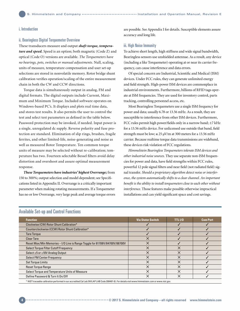
Available Set-up and Control Functions Function Via Stator Switch TTL I/O Com Port Clockwise (CW) Rotor Shunt Calibration*
Counterclockwise (CCW) Rotor Shunt Calibration*
Tare Torque
Clear Tare
Reset Max/Min Memories – I/O Line is Range Toggle for 81708V/84700V/88700V
Select Torque Filter Cutoff Frequency
Select ±5 or ±10V Analog Output
Select FM Center Frequency
Set Torque Limits
Reset Torque Range
Select Torque and Temperature Units of Measure
Define Password & Turn It On/Off
* NIST traceable calibration performed in our accredited Cal Lab (NVLAP LAB Code 200487-0). For details visit www.himmelstein.com or www.nist.gov.
© 2017 S. Himmelstein and Company—all rights reserved www.himmelstein.com4
S. Himmelstein and Company Installation and Operation Manual, Revision E
Installation and Operation Manual, Revision E S. Himmelstein and Company
A. Mechanical InstallationA.1 Applicability
This discussion is applicable to all MCRT® 81008V, 84000V,
85000V, 86000V, 87000V, 81708V, 84700V and 88700V Series Devices.
A.2 Rotor Mechanical Installation
The Rotor is installed between the driven and driving member.
It may be bolted to either. The torsion load should be carried by
face friction rather than bolt shear. To accomplish that and avoid
slippage, use eight Socket Head Cap Screws with tensile strength
≥ 170,000 psi (1,200 Mpa), i.e. Unbrako or equal. They should be
tightened in accordance with the tabulated torque values.
Inevitably, the driving and driven shafts won’t be perfectly
aligned and they also have runout. Bolting a Torquemeter rotor to
either increases its shaft length. The resultant extended shaft will
have somewhat increased runout and misalignment but is other-
wise equivalent to the set-up without the Torquemeter installed.
Therefore, like the set-up before Torquemeter installation, a
flexible coupling is required between the installed Torquemeter
rotor and the second user flange.
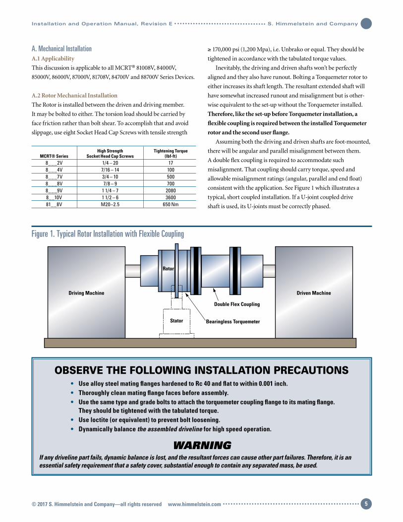
Assuming both the driving and driven shafts are foot-mounted,
there will be angular and parallel misalignment between them.
A double flex coupling is required to accommodate such
misalignment. That coupling should carry torque, speed and
allowable misalignment ratings (angular, parallel and end float)
consistent with the application. See Figure 1 which illustrates a
typical, short coupled installation. If a U-joint coupled drive
shaft is used, its U-joints must be correctly phased.
OBSERVE THE FOLLOWING INSTALLATION PRECAUTIONS • Use alloy steel mating flanges hardened to Rc 40 and flat to within 0.001 inch. • Thoroughly clean mating flange faces before assembly. • Use the same type and grade bolts to attach the torquemeter coupling flange to its mating flange. They should be tightened with the tabulated torque. • Use loctite (or equivalent) to prevent bolt loosening. • Dynamically balance the assembled driveline for high speed operation.
WARNINGIf any driveline part fails, dynamic balance is lost, and the resultant forces can cause other part failures. Therefore, it is an essential safety requirement that a safety cover, substantial enough to contain any separated mass, be used.
Driving Machine Driven Machine
Double Flex Coupling
Bearingless Torquemeter
Rotor
Stator
Figure 1. Typical Rotor Installation with Flexible Coupling
High Strength Tightening Torque MCRT® Series Socket Head Cap Screws (lbf-ft) 8___2V 1/4 – 20 17 8___4V 7/16 – 14 100 8___7V 3/4 – 10 500 8___8V 7/8 – 9 700 8___9V 1 1/4 – 7 2080 8__10V 1 1/2 – 6 3600 81__8V M20–2.5 650 Nm
© 2017 S. Himmelstein and Company—all rights reserved www.himmelstein.com 5
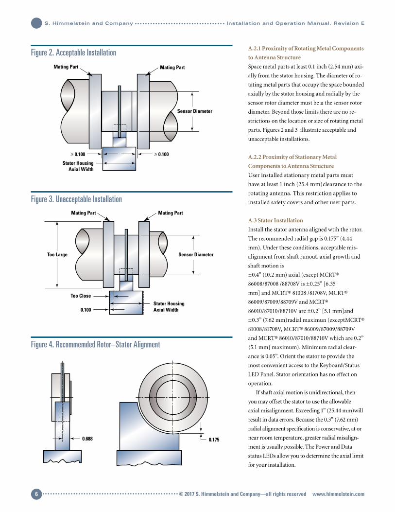
A.2.1 Proximity of Rotating Metal Components
to Antenna Structure
Space metal parts at least 0.1 inch (2.54 mm) axi-
ally from the stator housing. The diameter of ro-
tating metal parts that occupy the space bounded
axially by the stator housing and radially by the
sensor rotor diameter must be ≤ the sensor rotor
diameter. Beyond those limits there are no re-
strictions on the location or size of rotating metal
parts. Figures 2 and 3 illustrate acceptable and
unacceptable installations.
A.2.2 Proximity of Stationary Metal
Components to Antenna Structure
User installed stationary metal parts must
have at least 1 inch (25.4 mm)clearance to the
rotating antenna. This restriction applies to
installed safety covers and other user parts.
A.3 Stator Installation
Install the stator antenna aligned wtih the rotor.
The recommended radial gap is 0.175” (4.44
mm). Under these conditions, acceptable mis-
alignment from shaft runout, axial growth and
shaft motion is
±0.4” (10.2 mm) axial (except MCRT®
86008/87008 /88708V is ±0.25” [6.35
mm] and MCRT® 81008 /81708V, MCRT®
86009/87009/88709V and MCRT®
86010/87010/88710V are ±0.2” [5.1 mm]and
±0.3” (7.62 mm)radial maximun (exceptMCRT®
81008/81708V, MCRT® 86009/87009/88709V
and MCRT® 86010/87010/88710V which are 0.2”
5.1 mm] maximum). Minimum radial clear-
ance is 0.05”. Orient the stator to provide the
most convenient access to the Keyboard/Status
LED Panel. Stator orientation has no effect on
operation.
If shaft axial motion is unidirectional, then
you may offset the stator to use the allowable
axial misalignment. Exceeding 1” (25.44 mm)will
result in data errors. Because the 0.3” (7.62 mm)
radial alignment specification is conservative, at or
near room temperature, greater radial misalign-
ment is usually possible. The Power and Data
status LEDs allow you to determine the axial limit
for your installation.
Figure 2. Acceptable Installation
Figure 3. Unacceptable Installation
Figure 4. Recommemded Rotor–Stator Alignment
Stator HousingAxial Width
Sensor Diameter
Mating Part Mating Part
≥ 0.100 ≥ 0.100
Stator HousingAxial Width
Sensor DiameterToo Large
Too Close
0.100
Mating PartMating Part
0.1750.688
© 2017 S. Himmelstein and Company—all rights reserved www.himmelstein.com6
S. Himmelstein and Company Installation and Operation Manual, Revision E

Installation and Operation Manual, Revision E S. Himmelstein and Company
B. Electrical InstallationB.1 Applicability
This discussion is applicable to all models including MCRT® 81008V,
84000V, 85000V, 86000V, 87000V, 81708V, 84700V and 88700V Series
devices.
B.2 Stator Connectors
The Power Connector and Fuse are on one end; see Figure 5.
A terminal is provided for Earth Grounding the stator
housing. You may move it to the most convenient of the 4
tapped holes. Mating connectors are supplied. The Optional
Speed Pickup(s) has an integral connector to accommodate its
Signal and Power leads; see Section F for connections
and operating information.
B.2.1 Analog Torque Output
Connector Pinout
B.2.2 Input Power Connector Pinout
Nominal input power is 10 to 26 VDC at 6 watts with antenna
aligned, to 9 watts with maximum specified misalignment.
The Power Source should be capable of delivering 2
amperes peak start-up current for each powered
Torquemeter. Shielded cable will perform best in noisy
environments and is recommended.
CautionDon’t connect a Transducer to a Power Supply that also
drives inductors, valves or solenoids. Induced switching
transients may cause noise and/or damage.
Note: After initial installation or driveline reconfiguration,
startup may take several minutes while the system adapts to
the installed metal environment. Thereafter startup will be
virtually instantaneous.
B.2.3 I/O and FM Output Connector Pinout
Function Pin
Invoke CW Rotor Shunt Calibration A
Invoke CCW Rotor Shunt Calibration B
FM Signal Out (TTL Square Wave) C
Ground D
Invoke Tare E
Clear Tare F
Reset Max/Min and Latched Limits Except, G Toggle Range for MCRT® 81708V/84700V/88700V Series
Data OK (Open collector, +7V @ 20 mA, max) H
Function Pin Analog out A Ground B
Function Pin + Power In C Shield B Power Ground A
Figure 5. Stator Assembly Showing Connector, Keypad & Status LED Location
S.HIMMELSTEIN
AND COMPANY
DATA
TEMP
POWER
+CAL
-CAL
Digital I/O& FM Out
Ground TerminalAnalog Out
RS232/422/485Com Ports
Power Input
Fuse, 2 Amp
© 2017 S. Himmelstein and Company—all rights reserved www.himmelstein.com 7

All Input lines are TTL Low True Logic, i.e., use a 0 to invoke a func-
tion. There are two output lines, Pin C and Pin H. Pin C outputs
FM Torque data as a TTL square wave. Pin H outputs the DATA OK
signal as High True, i.e. it is High when DATA is OK and Low when
it is not. This Open Collector line must be powered by the user with
7 VDC maximum. A 4.7 kΩ pull-up resistor is recommended.
B.2.4 RS232/422/485 Connector Pinout
Notes: Two identical 6 pin connectors are wired in parallel. This
arrangement facilitates RS485 connection of multiple
Torquemeters to a single host computer. You may use either
for RS232 or RS422 service. Data is transmitted in bytes
with a start and a stop bit, no parity and no flow control.
TXD and RXD apply to RS232.
± TXD and ±RXD apply to RS422 and RS485 formats.
Data is transmitted at 115.2 kBaud. See Figures 6, 7 and 8 for
connection diagrams.
Figure 6. RS232 Cable Connections
Figure 7. RS422 Cable Connections
Function Pin
+TXD A
Ground for RS422/485, Open for RS232 B
Ground C
-RXD or TXD D
+RXD or RXD E
-TXD F
B.2.4.1 RS232 Connecting Cable Diagram
B.2.4.2 RS422 Connecting Cable Diagram
Computer Torquemeter
TXD
TXDRXD
RXD
GND GND
3
2
5
E
D
C
224-8359-XX (2PR, SHLD, 22AWG)
SoftwareSwitched
120Ω
ComputerRS232
RS232 to RS422/485 Converter330-0001
+RXD
-RXD
+TXD
-TXD
GND
+RXD
+RXD
-RXD
-RXD+TXD
+TXD
-TXD
-TXD
GND GND
A
F
E
D
C
BRS485/RS232
224-8360-XX (3PR, SHLD, 22AWG)
120Ω
Torquemeter
For cable runs greater than 500 feet, terminate RXD data signal at the computer andthe Torquemeter with 120Ω. Termination resistors are included on torquemeter andcan be switched in and out via BLT-WIN software.
120Ω
Softwareswitched
© 2017 S. Himmelstein and Company—all rights reserved www.himmelstein.com8
S. Himmelstein and Company Installation and Operation Manual, Revision E
Installation and Operation Manual, Revision E S. Himmelstein and Company
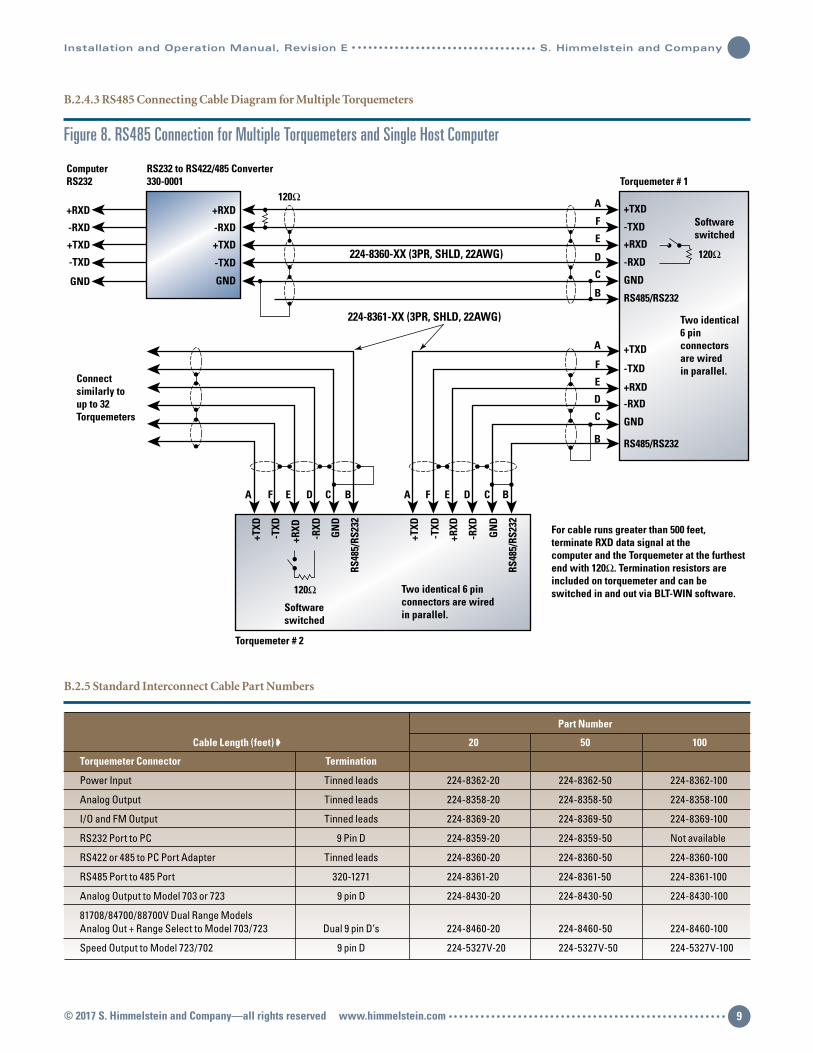
Figure 8. RS485 Connection for Multiple Torquemeters and Single Host Computer
B.2.4.3 RS485 Connecting Cable Diagram for Multiple Torquemeters
B.2.5 Standard Interconnect Cable Part Numbers
Part Number
Cable Length (feet) 20 50 100
Torquemeter Connector Termination
Power Input Tinned leads 224-8362-20 224-8362-50 224-8362-100
Analog Output Tinned leads 224-8358-20 224-8358-50 224-8358-100
I/O and FM Output Tinned leads 224-8369-20 224-8369-50 224-8369-100
RS232 Port to PC 9 Pin D 224-8359-20 224-8359-50 Not available
RS422 or 485 to PC Port Adapter Tinned leads 224-8360-20 224-8360-50 224-8360-100
RS485 Port to 485 Port 320-1271 224-8361-20 224-8361-50 224-8361-100
Analog Output to Model 703 or 723 9 pin D 224-8430-20 224-8430-50 224-8430-100
81708/84700/88700V Dual Range Models Analog Out + Range Select to Model 703/723 Dual 9 pin D’s 224-8460-20 224-8460-50 224-8460-100
Speed Output to Model 723/702 9 pin D 224-5327V-20 224-5327V-50 224-5327V-100
ComputerRS232
RS232 to RS422/485 Converter330-0001
+RXD
-RXD
+TXD
-TXD
GND
+RXD
-RXD
+TXD
-TXD
GND
A F E D C B A F E D C B
A
F
E
D
C
B
A
F
E
D
C
B
+RXD
-RXD
+TXD
-TXD
GND
RS485/RS232
+RXD
-RXD
+TXD
-TXD
GND
RS485/RS232
+RXD
-RXD
+TXD
-TXD
GN
D
RS48
5/RS
232
+RXD
-RXD
+TXD
-TXD
GN
D
RS48
5/RS
232
224-8360-XX (3PR, SHLD, 22AWG)
224-8361-XX (3PR, SHLD, 22AWG)
120Ω
120Ω
Torquemeter # 2
Torquemeter # 1
For cable runs greater than 500 feet, terminate RXD data signal at the computer and the Torquemeter at the furthestend with 120Ω. Termination resistors are included on torquemeter and can beswitched in and out via BLT-WIN software.
Connectsimilarly toup to 32Torquemeters
Softwareswitched
Two identical 6 pinconnectors are wiredin parallel.
120Ω
Softwareswitched
Two identical6 pinconnectors are wiredin parallel.
© 2017 S. Himmelstein and Company—all rights reserved www.himmelstein.com 9
B.2.6 RS422/485 and USB Adapters
When the cable run from the Torquemeter to the PC is greater than
50 feet, you should use an adapter to convert the computer port for
differential signal transfer using either the RS422 or RS485 Mode.
RS422 is used when connecting to a single Torquemeter. RS485
is used when two or more Torquemeters are connected to a single
host computer. For cable runs greater than 500 feet, the internal
120 ohm cable terminations should be connected using the
furnished software.
When you connect multiple Torquemeters to a single computer
using RS485 communications, you must assign a unique
identification (ID) to each Torquemeter. That can be done
with the supplied interface software.
We can furnish a PC RS232 port adapter or, a USB adapter for
the port conversion. They plug into the PC com port connector.
The Torquemeter cable connects to the adapter terminal block.
Hence the cable has tinned leads on the computer end.
The RS232 to RS422/485 adapter is Part Number 330-0001;
external power is not required.
The USB to RS232 adapter is Part Number 330-0002; external
power is not required.
The USB to RS422/485 adapter is Part Number 330-0003;
external power is not required.
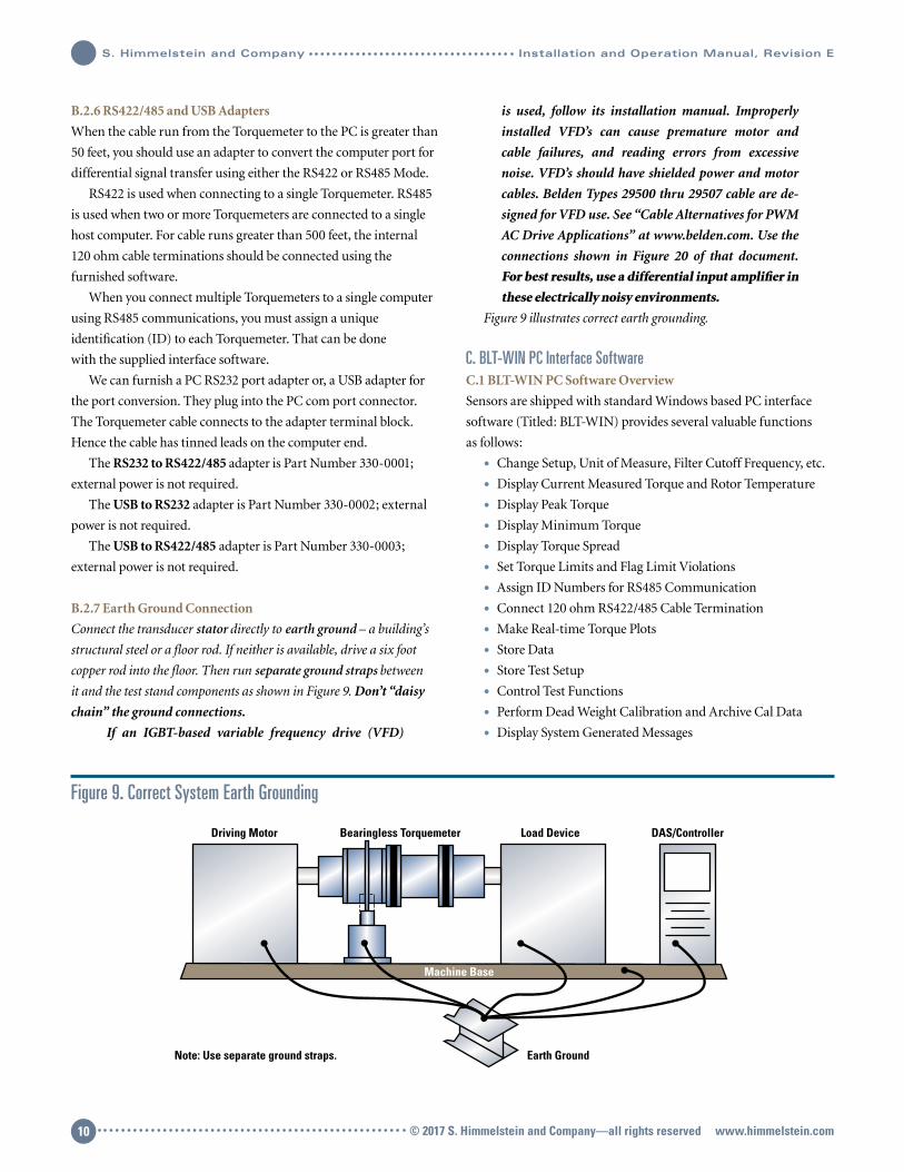
B.2.7 Earth Ground Connection
Connect the transducer stator directly to earth ground – a building’s
structural steel or a floor rod. If neither is available, drive a six foot
copper rod into the floor. Then run separate ground straps between
it and the test stand components as shown in Figure 9. Don’t “daisy
chain” the ground connections.
If an IGBT-based variable frequency drive (VFD)
is used, follow its installation manual. Improperly
installed VFD’s can cause premature motor and
cable failures, and reading errors from excessive
noise. VFD’s should have shielded power and motor
cables. Belden Types 29500 thru 29507 cable are de-
signed for VFD use. See “Cable Alternatives for PWM
AC Drive Applications” at www.belden.com. Use the
connections shown in Figure 20 of that document.
For best results, use a differential input amplifier in
these electrically noisy environments.
Figure 9 illustrates correct earth grounding.
C. BLT-WIN PC Interface SoftwareC.1 BLT-WIN PC Software Overview
Sensors are shipped with standard Windows based PC interface
software (Titled: BLT-WIN) provides several valuable functions
as follows:
• Change Setup, Unit of Measure, Filter Cutoff Frequency, etc.
• Display Current Measured Torque and Rotor Temperature
• Display Peak Torque
• Display Minimum Torque
• Display Torque Spread
• Set Torque Limits and Flag Limit Violations
• Assign ID Numbers for RS485 Communication
• Connect 120 ohm RS422/485 Cable Termination
• Make Real-time Torque Plots
• Store Data
• Store Test Setup
• Control Test Functions
• Perform Dead Weight Calibration and Archive Cal Data
• Display System Generated Messages
Figure 9. Correct System Earth Grounding
Earth Ground
DAS/ControllerBearingless TorquemeterDriving Motor Load Device
Note: Use separate ground straps.
Machine Base
© 2017 S. Himmelstein and Company—all rights reserved www.himmelstein.com10
S. Himmelstein and Company Installation and Operation Manual, Revision E
Installation and Operation Manual, Revision E S. Himmelstein and Company
Functions and parameters are chosen with mouse clicks from
options shown on the screen and/or entered via the PC keyboard.
Page 1 lists the installed setup, when shipped. A user may write his
own communication software; see Appendix V for information on
the serial command structure.
C.2 Change Sensor/Test Setup
• Select any of 10 units of measure. Default units are: lbf-in.
• Select any of 11 data filter cutoff frequencies; 1 to 1 kHz in
1-2-5 steps plus 3 kHz.
• Select ±5V or ±10V full scale analog output.
• Select FM center frequency, either 10, 20 or 40 kHz.
• Re-scale the torque range to any value ≤ the Torque
meter full scale. Re-scaling yields greater resolution
and ±5 or ±10V analog output at the lower torque
range. However, it will not have the backing of an
accredited calibration and it will have reduced tem-
perature performance. The Dual-Range MCRT®
81708V/84700V/88700V Torquemeters avoid those
problems. See Appendix III for additional information.
• Set software Torque Limits and assign them to Max/Min
data, or Current data, or Spread data. Limit response time is
determined by the users visual response (4 per second) and
acuity. However, it may be lower if the filter bandwidth is set
≤2 hertz. The limits are non-latching except, when they clas-
sify max/min data where they will latch. Use the software or
I/O line to reset max/mins and latched limits.
• Toggle MCRT® 81708V/84700V/88700V Range.
• Save data to disk.
• Store test setup on disk.
• Adjust the value of the analog output voltage. The output
voltage(s) is factory set at ±5.000V and ±10.000V and should
not be re-adjusted without accurate measuring equipment.
• Invoke or disable password protection and enter a new
password. Default condition is password protection off: the
default password is SHC. You can change the password to any
string but, should record the new one in a secure place.
• Assign Torquemeter ID for RS485 communication mode.
• Select Temperature units of measure. Default unit is °F.
Setup changes made with the Interface Software don’t require
recalibration. Any change will automatically re-configure depen-
dent parameters. For example, if units are changed from lbf-in to
Nm, torque data and Cal Checks will be correct without further
adjustments.
C.3 Display Measured Data
• Current Torque numeric data with unit of measure
• Torque Maximum and Minimum numeric data with unit of
measure
• Torque Spread numeric data with unit of measure
• Status of user set High and Low Torque Limits
• Real time plot of Torque
• Rotor Temperature numeric data
C.4 Control Test
You can initiate the following actions from a PC:
• Invoke CW and CCW Rotor Torque Bridge Shunt Cal Checks
• Invoke Tare Torque
• Clear Tare
• Toggle MCRT® 81708V/84700V/88700V Range
• Reset Torque Max/Mins
• Save current setup parameters
• Save Data to disk
C.5 Perform Dead Weight Calibration
Units are shipped with an NIST traceable dead weight calibration
performed in our accredited laboratory; a Calibration Certificate is
included with the sensor. The results of that calibration are stored
in non-volatile memory and automatically loaded on power up.
Remote Calibration Checks are referenced to it. They may be initi-
ated from a PC via the Com Port, via TTL I/O control or, from the
stator keypad.
The user can perform a dead weight calibration and store it in
memory. The interface program prompts you through the process.
If done, the original factory calibration will be archived as will
subsequent dead weight calibrations.
However, unless you have accurate, accredited calibration
facilities, you should not substitute a field calibration for the
factory calibration. Rather, you can perform a field calibration
for use as a rough check of operation. If an erroneous calibra-
tion is inadvertently stored, the factory calibration(s) may be
recovered.
C.6 Calibration Intervals
For continuous or intermittent service, make periodic Calibra-
tion Checks using the internal, NIST referenced shunt calibration
feature.
In applications requiring high accuracy, perform a dead weight
calibration in an Accredited Torque Calibration Laboratory at
intervals specified by your QC Procedures. If you do not have an
established QC procedure, then we recommend an initial one year
interval.
If the MCRT® Torquemeter is Overloaded or operates abnor-
mally, then calibrate/inspect it at once.
© 2017 S. Himmelstein and Company—all rights reserved www.himmelstein.com 11

Himmelstein offers certified dead weight calibration
service, traceable to NIST, for all its products. Its calibra-
tion laboratory is accredited (Laboratory Code 200487-0) by
NVLAP, an arm of the NIST. For further information visit our
website at www.himmelstein.com, or follow the accreditation
link at www.nist.gov.
D. Stator Keypad and Status IndicatorsD.1 Keypad
The following functions can be performed with keypad switches:
• Perform a CW rotor side shunt calibration.
• Perform a CCW rotor side shunt calibration.
• Tare Torque – accomplished by pressing and holding both
switches for at least 5 seconds.
Calibration should be done while the driveline torque is zero.
If locked-in torque is present, break a coupling to remove it.
D.2 Status Indicators
The keypad incorporates three status LED’s.
POWER LED — Yellow during power-up
Green when power is OK
Red when power has fault
DATA LED — Green when data is OK
Red if data fault
When the MCRT® 81708V/84700V/88700V is in its Low Range,
the GREEN DATA LED blinks slowly.
TEMPERATURE — Green in operating range
Red out of operating range
Should the user inadvertently install a mismatched stator
assembly, the system will:
• Flash the RED DATA LED
• Turn off the POWER LED and the TEMPERATURE LED
• The furnished software will publish a text warning on the
connected PC
• Clamp torque outputs (analog, fm and digital) to the
equivalent of Zero Torque
E. Operating & Safety ConsiderationsE.1 Applicability
This discussion is applicable to all models including MCRT®
81008V, 84000V, 85000V, 86000V, 87000V, 81708V, 84700V and
88700V Series devices.
E.2 Allowable Torque Loads
Operate an MCRT® Torquemeter within its full scale; see booklet
cover for rating of this device.
E.2.1 Overload Considerations
The Overload ratings of an MCRT® 81008V/84000V/86000V and
the High Range of the 81708V/84700V/88700V are 2 times their full
scale rating. The Overload rating of an MCRT® 85000V/87000V is
four times its full scale rating. The Overload rating of the MCRT®
81708V/84700V/88700V’s Low Range is ten times its range. This
Torquemeter’s Overload is listed on the cover sheet. The Torqueme-
ter will not yield (evidenced by a non-return to zero) or fail or suffer
a permanent change in performance if subjected to an instanta-
neous peak torque up to its Overload value.
Both the full scale and Overload ratings are based on the peak
stress seen by the transducer. They are independent of stress
duration except, for cyclical (or fatigue) loading considerations;
see ¶E.2.2. Virtually all rotary power producing and absorbing
devices produce pulsating rather than smooth torque and power.
Thus, in addition to its average torque and speed values, the
driveline torque usually includes a fundamental (driving) frequency
and superimposed harmonics. Torsional vibration magnitudes can
be amplified by the driveline. See Appendix IV and Bulletin 705 for
further information. The Figure 10 waveform is typical of what can
occur in the real world.
Therefore, a conservative design approach dictates the
Torquemeters’ Overload => twice the probable peak torque.
Reserve the region between the peak instantaneous torque
and the Torquemeter’s Overload rating as a safety margin for
unexpected loads. Do not knowingly operate in the Overload
region. If expected torques exceed the Overload, use a
Torquemeter with a higher Overload rating.
E.2.2 Fatigue Considerations
If the peak torque seen by an MCRT® Torquemeter is less than
half its Overload rating, it can handle full torque reversals with
infinite fatigue life. When peak torques are cyclical, and exceed
50% of the Overload rating, then fatigue failure can occur.
Figure 10. Reciprocating Machine Torque Profile
Peak Torque = Tp
Average Torque = Ta Tp ÷ Ta = 1.18
Time
00
Torq
ue
© 2017 S. Himmelstein and Company—all rights reserved www.himmelstein.com12
S. Himmelstein and Company Installation and Operation Manual, Revision E
Installation and Operation Manual, Revision E S. Himmelstein and Company
In those circumstances you should use a Torquemeter with
a higher Overload rating.
E.2.3 Starting High Inertias with Electric Motors
When started across the line, during the start, a motor’s
developed torque can be several times its rated torque. Thus,
a Digital Torquemeter sized to handle the motor’s rated load
torque, can be overloaded during starting. Drivelines are
particularly vulnerable when oversized motors drive light
duty, high inertia loads.
To avoid damage when starting high inertia loads, use a
Torquemeter with an Overload rating > the motor’s starting
torque, or limit the starting torque to a safe value. Techniques to
limit electric motor starting torques include:
• Use reduced voltage starting.
• Electronically limit the maximum motor current.
• Add as much inertia to the motor output as it can safely
start.
• Use “shock absorbing” couplings. Careful coupling
selection and thorough analysis is essential. Under some
conditions, such couplings can aggravate rather than
improve the situation.
E.3 Allowable Extraneous Loads
Any moment or force a Torquemeter sees, other than the
transmitted torque, is an extraneous load. Depending on the
installation, these could include bending moments, axial thrust
and shear force. Crosstalk errors from such loads are typically
1% of the applied bending or, 1% of the applied thrust when all
units are consistent. The Specification (Appendix III) contains
extraneous load limit values. You must stay within those limits
to avoid Torquemeter damage.
E.4 Overrange Considerations
A Torquemeters Overrange Rating is the highest torque
at which its output tracks its input. A High Level Output
Torquemeter must have a high Overrange Rating to be error-
free over its entire operating range. If it doesn’t, then peak and
average torque readings can have significant errors. Himmelstein
Bearingless Torquemeters have industries’ highest Overrange
Ratings; 150 to 300%, model dependent; see Specification
(Appendix III). Appendix I is a discussion of this critically
important parameter.
E.5 System Warm-up
After installation or before driveline reconfiguration, allow at
least 45 minutes for the system to adapt to the installed metal
environment. Otherwise, allow a 5 minute warmup for 0.1% data
or 35 minutes to obtain the maximum measurement accuracy
F. Zero Velocity Speed Pickup OptionsF.1 Applicability
This section is applicable to both the Code O Optical and the
Code Z Magnetic Speed Pickups.
F.2 Optical (Code O) Zero Velocity Speed Pickup
Code O Optical Pickups can be mounted on either side of the
stator housing; See Figure 11A. If more convenient, you may
move it from the factory-installed position to the alternate
position by removing two retaining screws and re-installing it.
When used, Optical Pickups do not affect the Torquemeter’s
allowable rotor/stator axial and radial misalignment, which
makes them the preferred choice. Code O pickups are designed
to operate in any light environment, including bright sun-
light. A commercial lens/eyeglass cleaner may be used to clear
the lens should it and/or the reflective target pattern become
contaminated.
F.3 Magnetic (Code Z) Zero Velocity Speed Pickup
When used, Code Z Magnetic Pickups restrict allowable
rotor/stator misalignment to ±0.04 inches axially and ±0.02 inches
radially. They are used in very dirty environments where a Code O
pickup requires frequent cleaning. Rotor/Stator alignment should
center the pickup on the flanges’ machined slots, see Figure 11B and
related notes for alignment instructions.
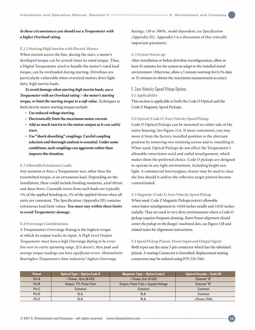
F.4 Speed Pickup Pinout, Power Input and Output Signal
Both types use the same 3 pin connector which has the tabulated
pinout. A mating Connector is furnished. Replacement mating
connectors may be ordered using P/N 224-5361.
Pinout Optical Type—Option Code O Magnetic Type—Option Code Z Optical Encoder – Code OE Pin A + Power, 10 to 26 VDC + Power, 6 to 15 VDC Channel “A” Pin B Output, TTL Pulse Train Output, Pulse Train ≈ Supply Voltage Channel “B” Pin C Common Common Common Pin D N.A. N.A. Common Pin E N.A. N.A. +Power, 5Vdc
© 2017 S. Himmelstein and Company—all rights reserved www.himmelstein.com 13
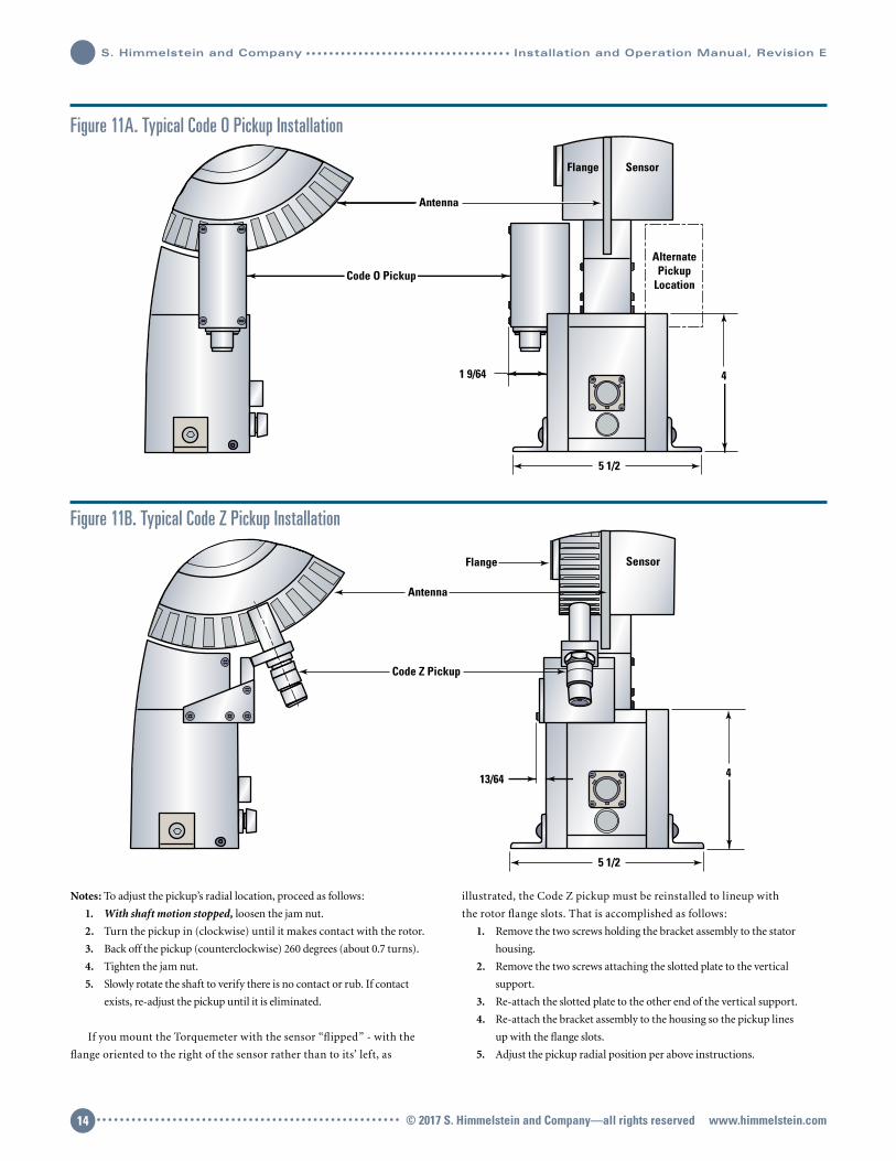
Notes: To adjust the pickup’s radial location, proceed as follows:
1. With shaft motion stopped, loosen the jam nut.
2. Turn the pickup in (clockwise) until it makes contact with the rotor.
3. Back off the pickup (counterclockwise) 260 degrees (about 0.7 turns).
4. Tighten the jam nut.
5. Slowly rotate the shaft to verify there is no contact or rub. If contact
exists, re-adjust the pickup until it is eliminated.
If you mount the Torquemeter with the sensor “flipped” - with the
flange oriented to the right of the sensor rather than to its’ left, as
illustrated, the Code Z pickup must be reinstalled to lineup with
the rotor flange slots. That is accomplished as follows:
1. Remove the two screws holding the bracket assembly to the stator
housing.
2. Remove the two screws attaching the slotted plate to the vertical
support.
3. Re-attach the slotted plate to the other end of the vertical support.
4. Re-attach the bracket assembly to the housing so the pickup lines
up with the flange slots.
5. Adjust the pickup radial position per above instructions.
Figure 11A. Typical Code O Pickup Installation
Figure 11B. Typical Code Z Pickup Installation
Code O Pickup
Antenna
Flange Sensor
1 9/64
5 1/2
AlternatePickup
Location
4
Sensor
5 1/2
4
Code Z Pickup
Flange
Antenna
13/64
© 2017 S. Himmelstein and Company—all rights reserved www.himmelstein.com14
S. Himmelstein and Company Installation and Operation Manual, Revision E

Installation and Operation Manual, Revision E S. Himmelstein and Company
15.88
Encoder Disc Assembly, 480 PPR
Encoder Read Head Assembly
Encoder Connector (PT02E-10-5P),
Mating Connector Supplied
0.18
1.47
0.51 0.81
1.78
15.24
1.47
148.54
31.75
139.70
Encoder Installation Notes:1. Encoder disc assembly is shipped unattached to the sensor. Install the encoder disc assembly to the torque sensor rotor using twelve (12) 4-40 x ½ flat head, self-locking, socket cap screws. Screws should be torqued to 6.9 Nm.2. Install torque sensor rotor assembly into the drivetrain using 24 M20 bolts torqued to 650 Nm.
3. Align and install the stator assembly to supporting fixture.4. Loosely attach encoder read-head assembly to the stator housing.
5. Place alignment tool over top of the read-head.
6. Position and then tighten read-head assembly in place.
7. Remove alignment tool.
Figure 11C. Typical Code OE Pickup Installation
© 2017 S. Himmelstein and Company—all rights reserved www.himmelstein.com 15


DefinitionA Torquemeter’s Overrange is the highest torque
at which measurement error is less than 0.1%
of full scale. Himmelstein expresses Overrange
as a percentage1 of full scale. A Torquemeter
must have an acceptable Overrange Rating to be
error- free over its operating range. If not, when
installed in a driveline, large errors can occur.
Note: Overrange of a mV/V output Torquemeter
is the lesser of its Overload Rating and the Over-
range of its external Signal Conditioner; again,
unless it is adequate, large measurement errors
will occur.
BackgroundRotary power producing and consuming devices
produce (or absorb) torque in a pulsating rather
than a smooth manner. That’s because they
have discrete poles and/or pistons and/or gear
meshes, etc. that generate complex forcing func-
tions. Furthermore, drivelines consist of several
inertias and torsion springs which resonate2 at
one or more frequencies. As a result, even under
APPENDIX I
OVERRANGE, A CRUCIAL ROTARY TORQUEMETER PARAMETER
1. When first published in Himmelstein Torquemeter specifica-
tions it was [Overrange Torque - Full Scale Torque]*100/[Full
Scale Torque]. That definition caused some confusion since
it is not consistent with the long accepted industry standard
for Transducer Percent Overload; mathematically [Torque
Overload Value]*100/[Full Scale Torque]. To eliminate
confusion, Himmelstein has elected to make the Overrange
and Overload definitions consistent, i.e., define Overrange
Percentage as [Overrange Torque]*100/[Full Scale Torque].
To further improve clarity, new Torquemeter Specifications
and reprints of older specifications will also contain actual
Overrange Torque in engineering units.
Figure 1. Torquemeter with 150% Overrange— Drive Has 45 Hz Torsional @ +/-50% of Full Scale
Figure 2. Torquemeter without Overrange— Drive Has 45 Hz Torsional @ +/-50% of Full Scale Which Results in Large Errors
0 0.01 0.02 0.03 0.04 0.05 0.06Time—Seconds
1601501401301201101009080706050403020100
Out
put T
orqu
e—Pe
rcen
t of T
orqu
emet
er F
ull S
cale
Average TorqueEquals Full Scale
Instantaneous Torque,Peak Equals 150% of Full Scale
0 0.01 0.02 0.03 0.04 0.05 0.06Time—Seconds
120
100
80
60
40
20
0
Out
put T
orqu
e—Pe
rcen
t of T
orqu
emet
er F
ull S
cale
Average Torque Equals 84%of Full Scale or is 16% Low
Instantaneous Torque Peak Equals Full Scale or is 33.3% Low
Installation and Operation Manual, Revision E S. Himmelstein and Company
© 2017 S. Himmelstein and Company—all rights reserved www.himmelstein.com 17

“constant load”, real world driveline torque is never constant. Instead,
it consists of an average torque with one or more superimposed
torsional components.
Torquemeter Range Selected for “Best Accuracy”Tables 1 and 2 show the response of two Torquemeters each
with 0.1% Combined Error. Both Torquemeters have a full-
scale rating equal to the engines rated (average) torque; the
generally accepted condition for assuring best accuracy. Table
1 Torquemeter has 150% Overrange, Table 2 Torquemeter has
no Overrange. Both monitor the same driveline which has a
torsional resonance at 45 Hertz (2700 rpm) with peak amplitude
equal to half the Average Torque.
The Torquemeter with 150% Overrange measures Peak and
Average Torques without error. The Torquemeter without
Overrange has a 16% error for Average Torque and a 33.3% error
for Peak Torque. That device incorrectly reports the engine power
and related driveline stresses to be much lower than actual.
Substantial, unacceptable real-world errors occur despite a
Torquemeter Combined Error specification of 0.1% and, with the
range selected for best accuracy.
The magnitude of such errors are a function of system
Average Torque= Full Scale Overrange—Percent of Full Scale
Dynamic Torque Peak Torque Errors (% of Full Scale) (% of Reading) 100 110 120 130 140 150
10
Peak Torque Error 9.09 0 0 0 0 0
Average Torque Error 3.19 0 0 0 0 0
20
Peak Torque Error 16.7 8.33 0 0 0 0
Average Torque Error 6.38 2.18 0 0 0 0
30
Peak Torque Error 23.1 15.4 7.69 0 0 0
Average Torque Error 9.58 5.1 1.77 0 0 0
40
Peak Torque Error 28.6 21.4 14.3 7.14 0 0
Average Torque Error 12.8 8.16 4.37 1.52 0 0
50
Peak Torque Error 33.3 26.7 20 13.3 6.67 0
Average Torque Error 16 11.9 7.22 3.88 1.36 0
Table 1
No Overrange Average Shaft Torque—Percent of Full Scale
Dynamic Torque Peak Torque Errors (% of Full Scale) (% of Reading) 50 60 70 80 90 100
10
Peak Torque Error 0 0 0 0 0 9.09
Average Torque Error 0 0 0 0 0 3.19
20
Peak Torque Error 0 0 0 0 9.09 16.7
Average Torque Error 0 0 0 0 2.43 6.38
30
Peak Torque Error 0 0 0 9.09 16.7 23.1
Average Torque Error 0 0 0 2.21 5.67 9.58
40
Peak Torque Error 0 0 9.09 16.7 23.1 28.6
Average Torque Error 0 0 2.17 5.46 9.07 12.8
50
Peak Torque Error 0 9.09 16.7 23.1 28.6 33.3
Average Torque Error 0 2.26 5.55 9.03 12.5 16
Table 2
S. Himmelstein and Company Installation and Operation Manual, Revision E
© 2017 S. Himmelstein and Company—all rights reserved www.himmelstein.com18
Installation and Operation Manual, Revision E S. Himmelstein and Company
Overrange, the amplitude of dynamic torque perturbations and
the average torque level. Table 1 illustrates the effect of Overrange
and Dynamic Torque Peak when the Average Torque is at full scale;
the generally accepted condition for best accuracy. Note, the no
Overrange device has an unacceptable error even with a Dynamic
Torque Peak as low as 10% of full scale.
Torque Measurement Systems Without OverrangeMany commercial Torquemeters, Signal Conditioners and most
Computer Data Acquisition Cards have no or little Overrange.
Table 2 shows their Overrange errors. As noted, such devices
operating at full scale have large errors even with small Dynamic
Torques. Unless operated downscale, a no Overrange device has
much larger errors when higher Dynamic Peak Torques are present.
To avoid such errors, you can greatly oversize the Torquemeter.
Oversizing increases temperature, linearity, and hysteresis errors,
and has other detrimental effects. Adequate Overrange is the
solution, Torquemeter oversizing is not.
Avoiding Fatigue FailuresA Torquemeter’s Overload Rating is the maximum torque that can
be applied without yielding its element or otherwise producing a
permanent change in its performance. Overload is usually specified
as a percentage of full scale. Cataloged Himmelstein Torquemeters
have Overload Ratings between 200% and 1,000% of full scale.
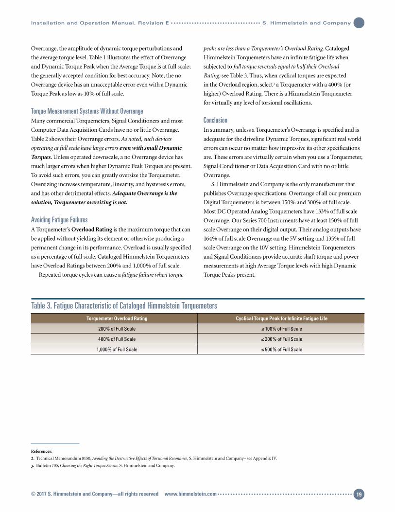
Repeated torque cycles can cause a fatigue failure when torque
peaks are less than a Torquemeter’s Overload Rating. Cataloged
Himmelstein Torquemeters have an infinite fatigue life when
subjected to full torque reversals equal to half their Overload
Rating; see Table 3. Thus, when cyclical torques are expected
in the Overload region, select3 a Torquemeter with a 400% (or
higher) Overload Rating. There is a Himmelstein Torquemeter
for virtually any level of torsional oscillations.
ConclusionIn summary, unless a Torquemeter’s Overrange is specified and is
adequate for the driveline Dynamic Torques, significant real world
errors can occur no matter how impressive its other specifications
are. These errors are virtually certain when you use a Torquemeter,
Signal Conditioner or Data Acquisition Card with no or little
Overrange.
S. Himmelstein and Company is the only manufacturer that
publishes Overrange specifications. Overrange of all our premium
Digital Torquemeters is between 150% and 300% of full scale.
Most DC Operated Analog Torquemeters have 133% of full scale
Overrange. Our Series 700 Instruments have at least 150% of full
scale Overrange on their digital output. Their analog outputs have
164% of full scale Overrange on the 5V setting and 135% of full
scale Overrange on the 10V setting. Himmelstein Torquemeters
and Signal Conditioners provide accurate shaft torque and power
measurements at high Average Torque levels with high Dynamic
Torque Peaks present.
References:
2. Technical Memorandum 8150, Avoiding the Destructive Effects of Torsional Resonance, S. Himmelstein and Company– see Appendix IV.
3. Bulletin 705, Choosing the Right Torque Sensor, S. Himmelstein and Company.
Torquemeter Overload Rating Cyclical Torque Peak for Infinite Fatigue Life
200% of Full Scale ≤ 100% of Full Scale
400% of Full Scale ≤ 200% of Full Scale
1,000% of Full Scale ≤ 500% of Full Scale
Table 3. Fatigue Characteristic of Cataloged Himmelstein Torquemeters
© 2017 S. Himmelstein and Company—all rights reserved www.himmelstein.com 19
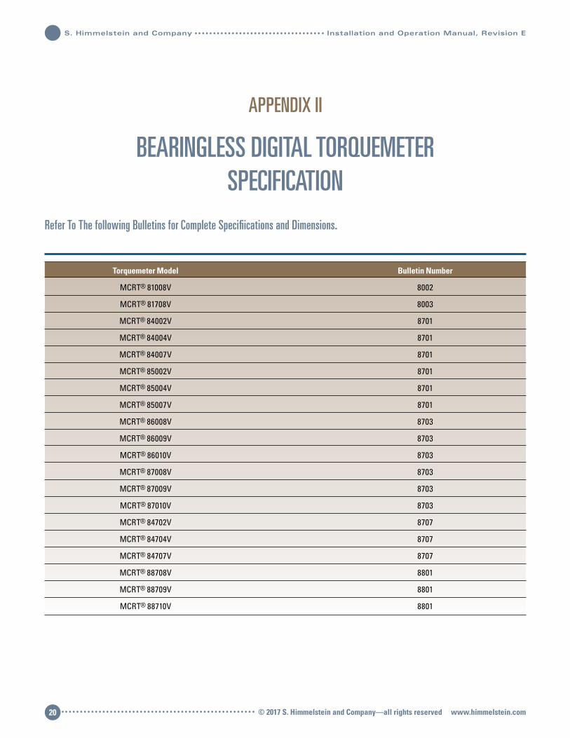
APPENDIX II
BEARINGLESS DIGITAL TORQUEMETERSPECIFICATION
Refer To The following Bulletins for Complete Specifiications and Dimensions.
Torquemeter Model Bulletin Number
MCRT® 81008V 8002
MCRT® 81708V 8003
MCRT® 84002V 8701
MCRT® 84004V 8701
MCRT® 84007V 8701
MCRT® 85002V 8701
MCRT® 85004V 8701
MCRT® 85007V 8701
MCRT® 86008V 8703
MCRT® 86009V 8703
MCRT® 86010V 8703
MCRT® 87008V 8703
MCRT® 87009V 8703
MCRT® 87010V 8703
MCRT® 84702V 8707
MCRT® 84704V 8707
MCRT® 84707V 8707
MCRT® 88708V 8801
MCRT® 88709V 8801
MCRT® 88710V 8801
S. Himmelstein and Company Installation and Operation Manual, Revision E
© 2017 S. Himmelstein and Company—all rights reserved www.himmelstein.com20
Installation and Operation Manual, Revision E S. Himmelstein and Company
Extending a Torquemeters measurement range1 can yield two
valuable benefits. That is, an extended range Torquemeter:
1. Reduces the number of Torquemeters needed to test a wide
torque range.
2. Can measure both high torsional peaks and low running
torque without risking torquemeter failure. Torquemeters
must have simultaneous outputs on each range to provide
this capability.
The advent of High Resolution Digital Torquemeters has
tempted some suppliers to mistakenly claim those benefits. Install-
ing an on-board, high resolution analog-to-digital converter (ADC)
is equivalent to placing one downstream of a conventional analog
output sensor. Both will provide high resolution and “extended”
range, but only with significantly degraded accuracy. That’s why all
Torquemeter manufacturers offer many ranges to handle different
capacities rather than a few models with extended range capability.
The table below compares performance of one such High Reso-
lution Digital Torquemeter to a Himmelstein, MCRT® 79007V(1-5),
Dual Range Torquemeter. Himmelstein Dual Range units are cali-
brated2, temperature-compensated and specified on each range and
both outputs are simultaneously available. The non- Himmelstein
unit has an advertised resolution of 0.001% of full scale; it has only
one signal output. Both devices have a full scale range of 100,000
lbf-in. The High Resolution Digital Torquemeter is re-scaled to
20,000 lbf-in to match the MCRT’s
Low Range. Error calculations include the only published error
specifications for the High Resolution device; Non-linearity, Zero
and Span Temperature Effects.
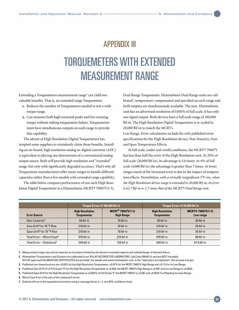
At full scale, under real-world conditions, the MCRT® 79007V
has less than half the error of the High Resolution unit. At 20% of
full scale (20,000 lbf-in), its advantage is 5.6 times. At 4% of full
scale (4,000 lbf-in) the advantage is greater than 7 times. At lower
ranges much of the increased error is due to the impact of tempera-
ture effects. Nonetheless, with a virtually insignificant 5°F rise, when
the High Resolution device range is extended to 20,000 lbf-in, its error
is 62.7 lbf-in or 2.7 times that of the MCRT® Dual Range unit.
APPENDIX III
TORQUEMETERS WITH EXTENDEDMEASUREMENT RANGE
1. Measurement range may only be lowered; an increase is limited by the device’s overload capacity and related danger of element failure.
2. Himmelstein Torquemeters and Systems are calibrated in our NVLAP ACCREDITED LABORATORY, Lab Code 200487-0, and are NIST traceable. NVLAP approved CALIBRATION CERTIFICATES are provided. For details visit www.himmelstein.com, or the “laboratory accreditation” link at www.nist.gov
3. Published non-linearity errors are ±0.05% for the High Resolution Torquemeter, ±0.07% for the MCRT 79007V High Range and ±0.1% for its Low Range.
4. Published Zero Drift (% of Full Scale/°F) for the High Resolution Torquemeter is ±0.003; the MCRT 79007V High Range is ±0.001 and its Low Range is ±0.0025.
5. Published Span Drift for the High Resolution Torquemeter is ±0.003% of Full Scale/°F; the MCRT 79007V is ±0.001 and ±0.0025 % of Reading for each Range.
6. Worst Case Error is the sum of the component errors.
7. Statistical Error is the expanded uncertainty using a coverage factor, k = 2, at a 95% confidence level.
Torque Errors @ 100,000 lbf-in Torque Errors @ 20,000 lbf-in
High Resolution MCRT® 79007V(1-5) High Resolution MCRT® 79007V(1-5) Error Source Torquemeter High Range Torquemeter Low range
Non-Linearity3 50 lbf-in 70 lbf-in 50 lbf-in 20 lbf-in
Zero Drift4 for 70 °F Rise 210 lbf-in 70 lbf-in 210 lbf-in 35 lbf-in
Span Drift5 for 70 °F Rise 210 lbf-in 70 lbf-in 210 lbf-in 35 lbf-in
Total Error—Worst Case6 470 lbf-in 210 lbf-in 470 lbf-in 90 lbf-in
Total Error—Statistical7 348 lbf-in 139 lbf-in 348 lbf-in 61.6 lbf-in
© 2017 S. Himmelstein and Company—all rights reserved www.himmelstein.com 21

A Torquemeter’s test temperature is the sum of the ambient
temperature and the rise generated during testing. Rotary power
transmission, absorbing and producing devices are never 100%
efficient. Their losses invariably generate heat and cause a
temperature rise during testing. After test shut down, component
temperatures usually rise further, during a soak period, before they
return to room temperature. At the test start, Zero Errors due to
ambient temperature can be electrically canceled. Uncompensated
test-generated temperature rises and ambient temperature changes
occurring during the test cannot be canceled and will produce
errors. Uncompensated temperature Span Errors can’t be removed
regardless of their source.
The High Resolution device employs a single shunt calibration
circuit. It develops a cal signal, at the signal chain input, at 75% of
full scale. That cal signal must be proportionately reduced when
the range is re-scaled. Since there is only one shunt cal circuit, the
reduction is handled by the processor after amplification and
digitizing. As a result, the calibration input to the signal chain
remains at 75% of full scale and can be much higher than the
torque signal when the range is re-scaled. To the extent it is larger
than the highest torque bridge output, it doesn’t provide a realistic
signal chain test. All MCRT® 79007V Dual Range torquemeters
have calibration signals for each range.
Re-scaling requires operation at proportionately reduced
bridge signal levels. Since system noise remains unchanged, the
measurement signal-to-noise ratio (SNR) is reduced. Externally
generated noise exacerbates this problem. Reduced SNR can be a
limiting factor when driveline or machine dynamics are at issue.
In summary, to achieve accurate, certifiable measurements,
Torquemeters must be calibrated in a facility accredited by an
internationally recognized agency such as NVLAP or A2LA. When
a Torquemeter is correctly calibrated, digital field re-scaling does
not transfer the accredited calibration to the re-scaled range(s).
An accredited calibration must be done on every range used for
accurate, traceable, certifiable measurements. Even when such
rigorous multi-range calibrations are done, re-scaled torquemeters
can suffer significant errors from temperature effects and other
factors. Himmelstein Series 79000V Dual Range Torquemeters
mitigate many of those errors and provide significantly higher
accuracy in extended range applications. Multi-range digital
versions of these Torquemeters with bearings and in bearingless
configurations will be available from Himmelstein in the future.
S. Himmelstein and Company Installation and Operation Manual, Revision E
© 2017 S. Himmelstein and Company—all rights reserved www.himmelstein.com22

Installation and Operation Manual, Revision E S. Himmelstein and Company
SummaryThe rapidly expanding use of diesel engines and a-c variable speed
drive systems has made it essential for test stand users and designers
to acquire a working knowledge of torsional effects. Both drive types
carry a much higher risk of associated component failures than ei-
ther spark ignition engines or other variable speed motor types. The
diesel’s high amplitude torsional output is well-known. The prob-
lems associated with a-c drives stem from the very wide range of
output torque forcing frequency. Unless such drivelines are analyzed
and modified where necessary, there is a high probability resonance
will fall within the operating speed range and cause component
failure. Technical Memorandum 8150 shows how to estimate
torsional resonant frequencies and describes how to avoid destruc-
tive effects. Both practical and theoretical aspects are included.
Several typical problems are analyzed and solutions presented.
Background DiscussionAll mechanical power-producing devices – hydraulic motors,
air motors, electric motors, internal combustion engines – have
discrete poles. As a result, their output torque is not developed
smoothly but has periodic torque pulsations or torsional vibrations.
These torque variations in turn, produce periodic velocity
variations or accelerations.
Thus, in addition to having an average torque and speed value,
the input (forcing function) to a shaft network has a fundametal
frequency and multiples or harmonics of that frequency. This
dynamic forcing function is applied to power transmitting and
consuming devices which invariably include complex mechani-
cal networks. When the fundamental forcing frequency, or one of
its harmonics, is equal to the torsional resonant frequency of the
network, a significant torque magnification can occur. That is,
the applied peak-to-peak torque variations can be increased by a
significant factor.
Avoiding ProblemsThe preferred method of avoiding the destructive effects of torsion-
al resonance is to place a flywheel (with a large moment of inertia)
between the source of torque pulsations and the remainder of
the network and/or to use torsionally soft elements (couplings,
shafts, etc.) in the driveline. Both tactics lower the system
resonant frequency (Fr). That reduction allows operation well
above resonance and thus attenuates rather than amplifies the
torsional effects. Stated in other words, the modified shaft network
is a low pass filter that prevents the torsionals from propagating to
the rest of the system.
If other considerations prohibit the use of a flywheel, it is
often possible to operate well below resonance. Under these
conditions, the resonant frequency should be at least 2.5 times
the highest forcing frequency. When operating well below
resonance, the fundamental torsional pulsations will be seen
by the shaft network without either significant magnification
or reduction. Therefore, all component stresses must be low
enough to survive the peak torques and be fatigue-rated for
the peak-to-peak torque reversals. Damping will reduce the
magnification factor at resonance and can be added by using
fluid couplings. However, they introduce power loss which is
not acceptable in most applications.
Since all driveline components must handle the peak torque
– the sum of the average driveline torque and the peak torque
variation – one or more of those components can fail even though
it is conservatively rated to handle the average torque. A fatigue
failure is most likely to occur when high frequency torsional
vibrations are present. However, if the resultant peak torque is
high enough, even a yield failure is possible.
Figure 1 illustrates the torque multiplication effect of torsional
resonance. When the forcing function frequency (Ff) is equal
to the torsional resonant frequency (Fr), the multiplication is a
maximum. It can approach infinity with no damping present.
In severe service, such as diesel drivelines, it is not unusual to
find resonant torque (and therefore stress) magnifications of
two to seven times. From the figure, one can see the torsional
variations are reduced in amplitude, rather than increased,
when the torsional resonant frequency is well below the
forcing frequency.
APPENDIX IV
AVOIDING THEDESTRUCTIVE EFFECTS OF TORSIONAL RESONANCE
© 2017 S. Himmelstein and Company—all rights reserved www.himmelstein.com 23

Useful FormulaeIn diesel drivelines, it is especially important that the torsional
resonant frequency be well below the operating speed range. A
mechanical schematic of a diesel engine dynamometer is shown
in Figure 2. In such a dynamometer the test engine drives the
absorber through a torquemeter and flexible couplings. It may
be classified as a two mass, single spring system and is typical of
motor-generator sets and similar machinery installations. The
inertia of the load (J2) and the test engine flywheel and crankshaft
(J1) are usually large compared to the inertia of the torquemeter
and the shaft couplings. Thus, the system resonant frequency may
be computed by using Equation 1 where,
J1 is the moment of inertia of the engine in LB-IN SEC2
J2 is the moment of inertia of the absorber in LB-IN SEC2
K is the torsional stiffness of the torquemeter in LB-IN/RADIAN
10.
1.0
0.10.1 1.0 10.
Mag
nific
atio
n Fa
ctor
FF/FR
Low DampingNo Damping
Large Damping
Over Damped
Figure 1. Magnification Factor vs. FF/FR
⎧ 30 ⎫ ⎧ K (J1 + J2) ⎫1/2
FR = CPM . . . . . . . . . . . . . . . . . . . . . . . . . . . . . . . . . . . . . . . . . . . . . . . . . . . . . . . . . . . . . . . . . . . . . . . . . . . . . . . . . . . . . . . . . . . . . . . . . . . . . . . . . . . . . . . . . . . . . (1) ⎩ π ⎭ ⎩ ( J1 ) ( J2 ) ⎭
Maximum* Magnification = ⎧ 1 ⎫ . . . . . . . . . . . . . . . . . . . . . . . . . . . . . . . . . . . . . . . . . . . . . . . . . . . . . . . . . . . . . . . . . . . . . . . . . . . . . . . . . . . . . . . . . . . . . . . . . . . . . . . . . . (2) 1 - ⎧ FF ⎫2
* = Assumes No Damping ⎩ ⎩ RR ⎭ ⎭
J1 = J2 LB - IN SEC2 . . . . . . . . . . . . . . . . . . . . . . . . . . . . . . . . . . . . . . . . . . . . . . . . . . . . . . . . . . . . . . . . . . . . . . . . . . . . . . . . . . . . . . . . . . . . . . . . . . . . . . . . . . . . . . . . . (3)
⎧ J2 ⎫ ⎧ πFR ⎫2 - 1
⎩ K ⎭ ⎩ 30 ⎭
K = ⎧ πFR ⎫2 ⎧ (J1) (J2) ⎫
LB - IN/RADIAN . . . . . . . . . . . . . . . . . . . . . . . . . . . . . . . . . . . . . . . . . . . . . . . . . . . . . . . . . . . . . . . . . . . . . . . . . . . . . . . . . . . . . . . . . . . . . . . . . . . . . . . . (4) ⎩ 30 ⎭ ⎩ (J1 + J2) ⎭
For a Solid Steel Cylinder with Diameter = D INCHES Length = L INCHES
J = LD4 LB - IN SEC2 . . . . . . . . . . . . . . . . . . . . . . . . . . . . . . . . . . . . . . . . . . . . . . . . . . . . . . . . . . . . . . . . . . . . . . . . . . . . . . . . . . . . . . . . . . . . . . . . . . . . . . . . . . . . . . . . . . . . . . . . . . . . . . . . . . . (5) 13908
For a Solid Steel Torsion “Spring” with Diameter = D INCHES Length = L INCHES
K =
1.178 X 10⁶ D4 LB - IN/RADIAN . . . . . . . . . . . . . . . . . . . . . . . . . . . . . . . . . . . . . . . . . . . . . . . . . . . . . . . . . . . . . . . . . . . . . . . . . . . . . . . . . . . . . . . . . . . . . . . . . . . . . . . . . . . . . . (6)
L
Shaft sections connected in series will have an equivalent spring constant of KE
KE = 1 1 + 1 + 1 • • • • • + 1
. . . . . . . . . . . . . . . . . . . . . . . . . . . . . . . . . . . . . . . . . . . . . . . . . . . . . . . . . . . . . . . . . . . . . . . . . . . . . . . . . . . . . (7)
K1 K2 K3 KN
where K1, K2, K3, . . . . . KN are spring constants of individual shafts
S. Himmelstein and Company Installation and Operation Manual, Revision E
© 2017 S. Himmelstein and Company—all rights reserved www.himmelstein.com24

Installation and Operation Manual, Revision E S. Himmelstein and Company
Practical Examples
GeneralTorsional resonance is of great practical importance in the
examples analyzed. The first two cover diesel engines which
produce high amplitude torque variations. A motor with
variable frequency drive system is discussed in Case 3. Analysis
of variable frequency drives is necessary because their speed
ranges are typically 5 to 15 times greater than diesel engines
and, because the probability that destructive resonance will
occur increases with the speed range.
Case 1, A Safe Diesel InstallationA 2,000 HP at 1,050 RPM, 12 cylinder, 4 cycle diesel engine is to
be tested on an engine dynamometer over the speed range from
400 to 1,200 RPM. An MCRT® 28008T(2-5) 200,000 LB-IN
torquemeter measures torque and speed. The absorber is a
generator/load combination. The following data summarizes
the installation characteristics:
J1 (engine crankshaft and flywheel) = 2,400 LB-IN SEC2
J2 (absorber inertia) = 4,530 LB-IN SEC2
K = 29,000,000 LB-IN/RADIAN (see Bulletin 761)
Ff, minimum = 400 RPM X 12*/2 = 2,400 CPM
Ff, maximum = 1,200 RPM X 12*/2 = 7,200 CPM
*Forcing frequency out of a 4 cycle IC engine is one-half the
product of the shaft speed and the number of cylinders.
Equations 1 and 2 can be used to calculate the shaft network
resonant frequency and maximum possible (no damping)
magnification factors. The results are summarized below:
Fr = 1,298 CPM (equal forcing frequency occurs at 216 RPM)
Maximum Possible Magnification at 400 RPM = 0.41
Maximum Possible Magnification at 1,200 RPM = 0.03
There is virtually no risk of damage from torsional resonance
because the resonant frequency of the network is significantly lower
(54%) than the lowest operating speed. Calculated maximum
magnification factors confirm this situation.
Case 2, A High Risk Diesel InstallationA 135 HP at 1,800 RPM, 6 cylinder, 2 cycle diesel engine will be
tested on an engine dynamometer. An MCRT® 28061T(6-3) 6,000
LB-IN torquemeter is used to measure torque and speed. Power
will be absorbed by an eddy current brake over the speed range
from 700 to 2,500 RPM. The following data summarizes
installation characteristics:
J1 = 0.75 LB-IN SEC2
J2 = 6.6 LB-IN SEC2
K = 2,430,000 LB-IN/RADIAN (see Bulletin 761)
Ff, minimum = 700 RPM X 6* = 4,200 CPM
Ff, maximum = 2,500 RPM X 6* = 15,000 CPM
*Forcing frequency out of a 2 cycle IC engine is the product of
shaft speed and the number of cylinders.
Using Equations 1 and 2 to calculate the shaft network resonant
frequency and magnification yields the following results:
Fr = 18,139 CPM (the equal forcing frequency occurs at
3,023 RPM)
Maximum Possible Magnification at 700 RPM = 1.06
Maximum Possible Magnification at 2,500 RPM = 3.16
Because the maximum operating speed is close to resonance,
the installation as described will have a high risk of failure. To avoid
this, the system resonant frequency must be reduced, preferably
to half (or less) of the lowest forcing frequency. Alternately, the
resonant frequency could be increased to 2.5 (or more) times the
highest forcing frequency.
In this case, it is impractical to significantly increase the system
resonant frequency, i.e., the inherent inertias cannot be reduced
and the torquemeter has an extremely high stiffness for its size.
The only practical approach is to reduce the resonant frequency by
decreasing the shaft stiffness and/or increasing system inertias.
Since the MCRT® 28061T(6-3) torquemeter is extremely stiff,
substituting an MCRT® 28004T(6-3) torquemeter will significantly
lower the resonant frequency. Its stiffness is 515,000 LB-IN/RA-
DIAN (see Bulletin 761). From equation 1, its use will reduce the
resonant frequency to 8,351 CPM (or 1,392 RPM). That resonance
LoadJ2
Driver
DriverJ1
TorquemeterFigure 2
© 2017 S. Himmelstein and Company—all rights reserved www.himmelstein.com 25
is within the operating speed range and could result in destructive
torque multiplications. Therefore, in addition to reducing the shaft
stiffness, it is necessary to increase the system inertia.
Using Equation 3 to calculate the driver inertia required to
reduce the resonant frequency to 1,800 CPM (300 RPM), yields a
negative inertia. That means it is not possible to achieve the desired
resonance by simply adding inertia to the driver side. The best way
out of this dilemma is to add a torsionally “soft” dynamometer
coupling shaft and, if needed, to add inertia on the driver side. A
reasonable selection is the Spicer 15-50 dynamometer shaft which
has a stiffness of 98,220 LB-IN /RADIAN and maximum ratings
of 7,680 LB-IN and 4,500 RPM. The equivalent network stiffness
for this shaft and the MCRT 28004T(6-3) torquemeter may be
calculated from Equation 7. It is 82,488 LB-IN/RADIAN.
The installation modified with this “soft” shaft and using the
MCRT® 28004T torquemeter has a resonant frequency (from
Equation 1) of 3,342 CPM. At the lowest speed the magnification
factor is 1.73. Thus, the resonant frequency is still too high to be
absolutely safe. It is necessary to add inertia to obtain a safe, 1,800
CPM (300 RPM) resonant frequency. Equation 3 is again used to
calculate the driver inertia needed. That value is 3.58 LB-IN SEC2.
The required minimum additional inertia becomes 3.58 less 0.75 or
2.83 LB-IN SEC2.
Assuming a 12” diameter steel disc, Equation 5 indicates that
1.9” of length will produce the desired inertia. Of course, the
resulting assembly should be dynamically balanced and fitted with
safety covers.
By way of summary, this critical application required both a
significant reduction of network stiffness and increased inertia to
obtain safe operating conditions — torsional resonance equal to
less than half the lowest forcing frequency. The modified system
characteristics are summarized below:
J1 = 3.58 LB-IN SEC2
J2 = 6.6 LB-IN SEC2
K = 82,488 LB-IN/RADIAN
Fr = 1,800 CPM (the equal forcing frequency occurs @ 300 RPM)
Ff, minimum = 4,200 CPM
Ff, maximum = 15,000 CPM
Maximum Possible Magnification @ 4,200 CPM (700 RPM) = 0.23
Maximum Possible Magnification @ 15,000 CPM (2,500 RPM) = 0.01
Case 3, A Variable Frequency Motor DrivelineA 15 HP, 4 pole, a-c motor with variable frequency speed control
package is to be tested on a dynamometer over the speed range
from 90 to 1,800 RPM (corresponds to 3 Hz to 60 Hz excitation).
The drive has current limiting, which in turn, limits the maximum
starting torque to 175% of rated or, 920 LB-IN. An MCRT® 28002T
(1-3) 1,000 LB-IN torquemeter measures torque and speed (see
Note). The absorber is an eddy current brake. The following data
summarizes the installation characteristics:
J1 = 0.48 LB-IN SEC2
J2 = 0.71 LB-IN SEC2
K = 70,100 LB-IN/RADIAN (see Bulletin 761)
Ff, minimum = 3 CPS X 60 SEC/MIN X 2* = 360 CPM
Ff, maximum = 60- CPS X 60 SEC/MIN X 2* = 7,200 CPM
*Forcing frequency out of an a-c motor is twice
the input power frequency.
Using Equations 1 and 2 to calculate the shaft network resonant
frequency and maximum possible magnification factors yields the
following results:
Fr = 4,724 CPM (equal forcing frequency occurs at 39.37
Hz input or 1,181 RPM)
Maximum Possible Magnification @ 3 Hz input = 1.01
Maximum Possible Magnification @ 60 Hz input = 0.76
Because the resonant frequency falls in the operating range,
the installation has a high risk of failure. The preferred solution
is to reduce the resonant frequency to one-half or less the lowest
forcing frequency. In this case, to 180 CPM or less. One approach is
to reduce shaft stiffness. Substituting the above values in Equation
4, indicates the shaft stiffness must be reduced to 101.75 LB-IN/
RADIAN, assuming the inertias remain unmodified. Inserting a
torsion spring with that stiffness will produce the desired change.
A one-inch diameter torsion rod will handle the required
torques. Substituting that diameter and the required stiffness in
Equation 6 yields a required spring length of 11,578”. Clearly, this
is an impractical approach. Similarly, if one calculates the inertia
required to reduce the system resonance to 180 CPM, the inertias
are totally impractical (about 395 LB-IN SEC2 for both driver and
load) for the physical size of the motor, absorber and torquemeter.
The only alternative is to raise the resonant frequency above the
operating range - to at least 2.5 times the highest forcing function or,
to 18,000 CPM. Again, using Equation 4 reveals the system spring
constant must be equal to or greater than 1,017,548 LB-IN/RADI-
AN. This can be accomplished by substituting a very stiff torqueme-
ter, such as the MCRT® 28060T(2-3), for the MCRT® 28002T. The
modified system characteristics are summarized as follows:
J1 = 0.48 LB-IN SEC2
J2 = 0.71 LB-IN SEC2
K = 1,375,000 LB-IN/RADIAN (see Bulletin 761)
Ff, minimum = 360 CPM
Ff, maximum = 7,200 CPM
Fr = 20,924 CPM
Fr/Ft Max = 2.91
Maximum Possible Magnification @ 360 CPM = 1.00
S. Himmelstein and Company Installation and Operation Manual, Revision E
© 2017 S. Himmelstein and Company—all rights reserved www.himmelstein.com26

Installation and Operation Manual, Revision E S. Himmelstein and Company
Maximum Possible Magnification @ 7,200 CPM = 1.13
Maximum Possible Magnification @ 14,400 CPM*=1.90
*Second harmonic of 7,200 CPM
By way of summary, the most practical solution to this problem
was to raise resonance well above the highest forcing frequency —
2.9 times. The relatively high magnification factor at 14,400 CPM
is acceptable because the magnitude of forcing function harmonic
input is substantially less than the magnitude of the fundamental.
NOTE:
When started across the line without current limiting, a-c motors can develop
several times their rated torque. In the Figure 2 dynamometer system, the
motor starting torque accelerates two major system inertias; J1 and J2.
Under these conditions the torque seen by the torquemeter is:
(Starting torque developed by motor) X (J2/(J1 + J2))For across-the-line starting without current limiting, the torquemeter’s full-
scale rating should be equal to or higher than this value. If it is not, a failure
may result.
© 2017 S. Himmelstein and Company—all rights reserved www.himmelstein.com 27
This specification of the serial communications for the Bearing-
less Torquemeter is subject to change at any time without notice.
Communication Port Settings • 8 data bits
• No parity
• No hardware / handshaking
• 1 start bit
• 1 stop bit
• 115200 baud
General conventions used in this document • OK stands for the string “OK”
• index is an alphanumeric character (A-Z or 0-9)
• CR is a carriage return ( M / 13 decimal / 0D hexadecimal /
15 octal)
• LF is a line feed ( J / 10 decimal / 0A hexadecimal / 12 octal)
• int is an integer number string (e.g. “1234”)
• long is a long integer number string (e.g. “1234567”)
• float is a floating point number string (e.g. “1234.57”)
• string is a string (e.g. “LB-IN”)
• hexNUM is a hexadecimal *string* that is NUM characters long
(e.g. hex4 could be “8FC4”)
General information • All messages to and from the Bearingless Torquemeter are
terminated with a CR or LF.
— The default termination character is CR.
• To set a value on the Bearingless Torquemeter, find the
message that retrieves the data you want to change. Then
append to that message the desired value of the parameter.
The Bearingless Torquemeter should respond with “OK”.
• All hexadecimal/binary data from the Bearingless
Torquemeter is in big-endian (MSB first) format.
In response to any command, the Bearingless Torquemeter returns one of the following: • “string” where string is the data requested.
• “OK” operation was successful
• Some error message starting with a “!” character. Some
common error messages include:
— “!BadArg” command has a bad argument
— “!BadIndex” The given index is out of range for the given
command.
— “!PasswordProtected” The parameter is password-
protected from change.
— “!Unknown” an unknown error occurred.
— “!xx” Command “xx” is unrecognized
Examples*ALL* messages to the Bearingless Torquemeter series start with
the torquemeter’s ID (or “*” for RS232) and end with a CR or a LF.
• Retrieve data:
Send “*DC” to the Bearingless Torquemeter. The return
message should look something like “1234.56”.
• Retrieve the filter:
Send “*FL” to the Bearingless Torquemeter. The return
message should be something like “07” which implies
(referring to the appropriate list under the “*FL” message)
that torque has a filter of 10 Hz.
• Set the filter to 100 Hz:
Refer to the list under the “*FL” (filter) command to find that
a 100 Hz filter corresponds to the value 4. Therefore, send
“*FL4” to the Bearingless Torquemeter. The Bearingless
Torquemeter should respond with “OK” if the operation was
successful.
• Apply the positive shunt calibration signal:
Send “*ASB” to the Bearingless Torquemeter. To remove this
signal, send “*ASA”.
APPENDIX V
SERIAL COMMUNICATIONS FOR THEBEARINGLESS TORQUEMETERS
S. Himmelstein and Company Installation and Operation Manual, Revision E
© 2017 S. Himmelstein and Company—all rights reserved www.himmelstein.com28
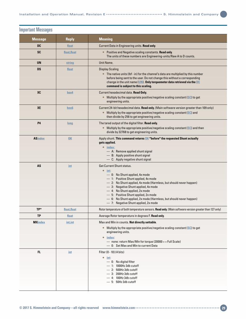
Installation and Operation Manual, Revision E S. Himmelstein and Company
Important Messages
Message Reply Meaning
DC float Current Data in Engineering units. Read only.
SC float,float • Positive and Negative scaling constants. Read only. The units of these numbers are Engineering-units/Raw A to D counts.
UN string Unit Name.
DS float Display Scaling • The native units (lbf - in) for the channel’s data are multiplied by this number before being sent to the user. Do not change this without a corresponding change in the unit name (UN). Only torquemeter data retrieved via the DC command is subject to this scaling.
XC hex4 Current hexadecimal data. Read Only. • Multiply by the appropriate positive/negative scaling constant (SC) to get engineering units.
XE hex6 Current 24-bit hexadecimal data. Read only. (Main software version greater than 109 only) • Multiply by the appropriate positive/negative scaling constant (SC) and then divide by 256 to get engineering units.
P4 long The tared output of the digital filter. Read only. • Multiply by the appropriate positive/negative scaling constant (SC) and then divide by 32768 to get engineering units.
ASindex OK Apply shunt. This command returns OK *before* the requested Shunt actually gets applied. • index: — A: Remove applied shunt signal — B: Apply positive shunt signal — C: Apply negative shunt signal
AS int Get Current Shunt status. • int: — 0: No Shunt applied, 4x mode — 1: Positive Shunt applied, 4x mode — 2: No Shunt applied, 4x mode (Harmless, but should never happen) — 3: Negative Shunt applied, 4x mode — 4: No Shunt applied, 2x mode — 5: Positive Shunt applied, 2x mode — 6: No Shunt applied, 2x mode (Harmless, but should never happen) — 7: Negative Shunt applied, 2x mode
TP* float,float Rotor temperature of both temperature sensors. Read only. (Main software version greater than 127 only)
TP float Average Rotor temperature in degrees F. Read only.
MXindex int,int Max and Min in counts. Not directly settable.
• Multiply by the appropriate positive/negative scaling constant (SC) to get engineering units.
• index: — none: return Max/Min for torque (20000 = = Full Scale) — 0: Set Max and Min to current Data
FL int Filter (0 - 10) (4 bits)
• int: — 0: No digital filter — 1: 1000Hz 3db cutoff — 2: 500Hz 3db cutoff — 3: 200Hz 3db cutoff — 4: 100Hz 3db cutoff — 5: 50Hz 3db cutoff
© 2017 S. Himmelstein and Company—all rights reserved www.himmelstein.com 29

Important Messages (Continued)
Message Reply Meaning
— 6: 20Hz 3db cutoff — 7: 10Hz 3db cutoff — 8: 5Hz 3db cutoff — 9: 2Hz 3db cutoff — 10: 1Hz 3db cutoff
MD string The model of the torquemeter
FS int The fullscale ‘counts’ for this torquemeter
SN string The serial number of the torquemeter
AFindex long Frequency Analog Output setup • index: — A: Frequency output at 0 (units: mHz) — B: Frequency output at torquemeter full scale (units: mHz)
AVindex long Voltage Analog Output setup • index: — A: Voltage output at 0 (units: micro-Volts) — B: Voltage output at torquemeter full scale (units: micro-Volts)
PSintstring OK Set password protection on/off • int: — 0: Off — 1: On • string — The password for the torquemeter
PS int Get the password protection state • int: — 0: Off — 1: On
PCXstring1Xstring2 OK Change password Xstring3 • The”X” represent any charactor not in any of the strings • string1: current password • string2: new password • string3: new pasword • Password is changed if and only if string1 equals the current password AND string2 and string3 are equal
ID char The ID of the torquemeter for the 485 communications
CM int The Communications Mode of the torquemeter • int: — 0: No Termination resistor — 1: Enable 1200 Ohm Termination resistsor during 485 Communication
TR string Tare Value • string — if string starts with ‘0’ - ‘9’, or ‘+’: Set Tare — else: Tare Torque
CEindex float Calibration Values • index: — A: Full Scale Value (units: lbf-in) — B: Positive Load Value (units: lbf-in) — C: Negative Load Value (units: lbf-in) — D: Positive Shunt Calibration Value (units: lbf-in) — E: Negative Shunt Calibration Value (units: lbf-in)
S. Himmelstein and Company Installation and Operation Manual, Revision E
© 2017 S. Himmelstein and Company—all rights reserved www.himmelstein.com30
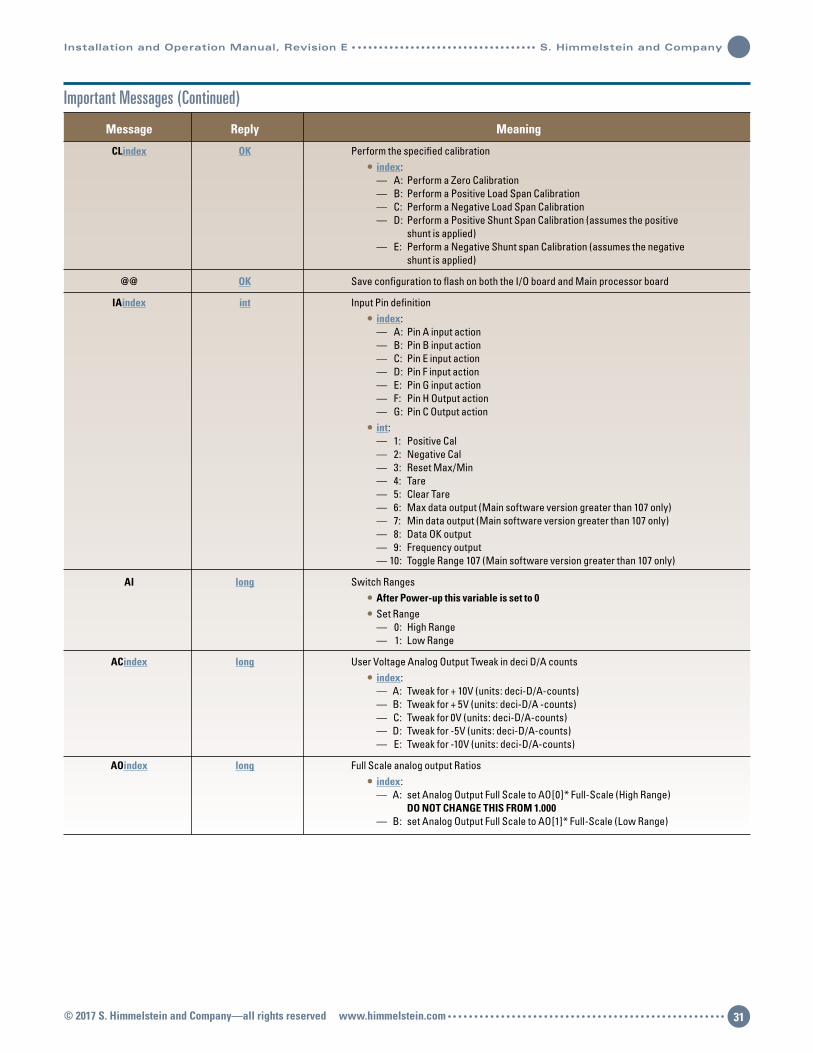
© 2017 S. Himmelstein and Company—all rights reserved www.himmelstein.com 31
Installation and Operation Manual, Revision E S. Himmelstein and Company
Message Reply Meaning
CLindex OK Perform the specified calibration • index: — A: Perform a Zero Calibration — B: Perform a Positive Load Span Calibration — C: Perform a Negative Load Span Calibration — D: Perform a Positive Shunt Span Calibration (assumes the positive shunt is applied) — E: Perform a Negative Shunt span Calibration (assumes the negative shunt is applied)
@@ OK Save configuration to flash on both the I/O board and Main processor board
IAindex int Input Pin definition • index: — A: Pin A input action — B: Pin B input action — C: Pin E input action — D: Pin F input action — E: Pin G input action — F: Pin H Output action — G: Pin C Output action • int: — 1: Positive Cal — 2: Negative Cal — 3: Reset Max/Min — 4: Tare — 5: Clear Tare — 6: Max data output (Main software version greater than 107 only) — 7: Min data output (Main software version greater than 107 only) — 8: Data OK output — 9: Frequency output — 10: Toggle Range 107 (Main software version greater than 107 only)
AI long Switch Ranges • After Power-up this variable is set to 0 • Set Range — 0: High Range — 1: Low Range
ACindex long User Voltage Analog Output Tweak in deci D/A counts • index: — A: Tweak for + 10V (units: deci-D/A-counts) — B: Tweak for + 5V (units: deci-D/A -counts) — C: Tweak for 0V (units: deci-D/A-counts) — D: Tweak for -5V (units: deci-D/A-counts) — E: Tweak for -10V (units: deci-D/A-counts)
AOindex long Full Scale analog output Ratios • index: — A: set Analog Output Full Scale to AO[0]* Full-Scale (High Range) DO NOT CHANGE THIS FROM 1.000 — B: set Analog Output Full Scale to AO[1]* Full-Scale (Low Range)
Important Messages (Continued)

S. Himmelstein and CompanyDesigning and Making the World’s Best Torque Instruments since 1960
2490 Pembroke Avenue, Hoffman Estates, IL 60169 USA • Tel: 847-843-3300 • Fax: 847-843-8488 • www.himmelstein.com