S. Girshick, U. Minnesota Aluminum Nanoparticle Synthesis and Coating Steven L. Girshick University...
29
S. Girshick, U. Minnesota Aluminum Nanoparticle Aluminum Nanoparticle Synthesis and Coating Synthesis and Coating Steven L. Girshick University of Minnesota
-
Upload
jordan-trevor-morton -
Category
Documents
-
view
216 -
download
2
Transcript of S. Girshick, U. Minnesota Aluminum Nanoparticle Synthesis and Coating Steven L. Girshick University...
S. Girshick, U. Minnesota
Aluminum Nanoparticle Aluminum Nanoparticle Synthesis and CoatingSynthesis and Coating
Steven L. GirshickUniversity of Minnesota

S. Girshick, U. Minnesota
Objectives1. Synthesize Al nanoparticles using
scalable plasma process
3. Coat particles to passivate surfaces
2. Maintain small primary particle size (high specific surface area) for high reactivity

S. Girshick, U. Minnesota
AcknowledgmentsProf. Michael ZachariahDr. Feng LiaoMr. Bin Zhang (PhD student)Mr. Bo Liu (MS student)Prof. Jeff RobertsDr. Ying-Chih Liao

S. Girshick, U. Minnesota
Why use thermal plasma?Why use thermal plasma?Atmospheric-pressure operation
Completely dissociates reactants to elements
High energy density high throughput in small reactor
Chemical flexibility
Continuous not batch process
Environmentally benign
Scalable

S. Girshick, U. Minnesota
2000 K1000 K
Complete dissociation
Nucleation front
Growth & coagulation
5000 KFlow
Diffusion & thermophoresis
Convection
Particle synthesis in a thermal plasmaParticle synthesis in a thermal plasma

S. Girshick, U. Minnesota
Nanoparticle reactorNanoparticle reactor

S. Girshick, U. Minnesota
Plasma torch / nozzle assembly
DC plasma torch
Injection ringNozzle holder

S. Girshick, U. Minnesota

S. Girshick, U. Minnesota
plasma
Large counterflow
plasma
counterflow
Formation of stagnation layer
Small counterflow
Al2O3 tube
counterflow
plasma

S. Girshick, U. Minnesota
Experimental Experimental DiagnosticsDiagnostics
Plasma torchAr/H2 30/0.5
slmI=200 A, ~10
kW
Counter flow Ar, 85
slm
Diagnostics port
53kPa
Injection Ring 4000 K, 88
kPa
Vacuum pump
Nozzle
Ejector
DMA, for size distribution
N2
Vacuum pump
Water cooled substrate, for RBS sample
TEM grid, for TEM and EDS
Filter holder
Sampling probe
-500
0
500
1000
1500
2000
2500
3000
3500
4000
4500
0 200 400 600 800 1000 1200
Effect of the Flowrate of TMA
0
100000
200000
300000
400000
500000
600000
700000
800000
900000
1000000
1 10 100
Diameter (nm)
dN/dLogDp (#/cc)
RBS
TEM EDS
Size distribution
By-pass
Glass beads and AlCl3 powder
Heated Ar100~200
sccm
Pressure gauge
Vacuum
Packed bed
Heating cable
Thermocouple

S. Girshick, U. Minnesota
Particle sampling & measurement
NanoDMA
TSICNC
3010AEjector
N265 PSI
Ejector
N265 PSI
CriticalOrifice
CriticalOrifice
Bypass
TEM GridHolder
Vacuum
Scanning mobility particle sizer (SMPS)
Sampled aerosol
Dilution

S. Girshick, U. Minnesota
Plasma power input 5–10 kW @ 210–250 A
Chamber pressure 400 Torr
Plasma flow ratesargon 30 slmhydrogen 0.5–2.0 slmAlCl3 10–20 sccm
Counterflowargon 85 slm
Operating conditionsOperating conditions

S. Girshick, U. Minnesota
mica
stainlesssteel
water cooling
by-pass
glass beadsand AlCl3powder
preheatedAr
vacuum
permeable stainlesssteel plate
heatingcable
insulation
line heated andinsulated
heated Ar +AlCl3 vapor
injection ring
nozzle port
tapered tube
AlCl3 vapor delivery system
Entire vapor flow passage is kept hot to avoid pre-condensation

S. Girshick, U. Minnesota
107
108
109
1010
10 100
Particle Diameter [nm]
counterflow on
counterflow off
AlCl3 with 200 sccm carrier gas
Counterflow reduces particle size
SMPS measurementsSMPS measurementsWith & w/out counterflowWith & w/out counterflow
S. Girshick, U. Minnesota
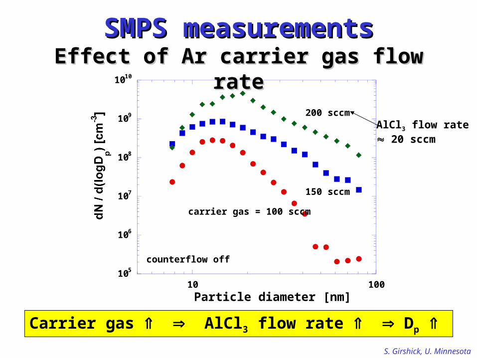
105
106
107
108
109
1010
10 100
Particle diameter [nm]
200 sccm
150 sccm
carrier gas = 100 sccm
counterflow off
SMPS measurementsSMPS measurementsEffect of Ar carrier gas flow rateEffect of Ar carrier gas flow rate
Carrier gas AlCl3 flow rate Dp
AlCl3 flow rate 20 sccm

S. Girshick, U. Minnesota
Inlet of SMPS Inlet of SMPS sampling probesampling probe

S. Girshick, U. Minnesota
Particles deposited onto TEM gridsParticles deposited onto TEM grids
Particles are mostly unagglommerated

S. Girshick, U. Minnesota
Particle on TEM gridParticle on TEM grid
TEM EDS
Background from Si3N4 TEM grid is shown in red
AlO

S. Girshick, U. Minnesota
QuickTime™ and aGraphics decompressor
are needed to see this picture.
Particle diameter 125 nm
Oxide layer thickness 2-5 nm
Oxide layer on particleOxide layer on particle
S. Girshick, U. Minnesota
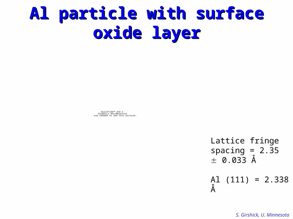
QuickTime™ and aGraphics decompressor
are needed to see this picture.
Lattice fringe spacing = 2.35 0.033 Å
Al (111) = 2.338 Å
Al particle with surface oxide layerAl particle with surface oxide layer
oxide layer
crystalline Al core

S. Girshick, U. Minnesota
Photoinduced CVDPhotoinduced CVD Gas-phase reactants are activated by UV/VUV photons
Excimer lamps are ideal photon source Commercially available Compact, long-life, reliable UV photons can break most chemical bonds Many wavelengths available
e.g., 172 nm (Xe2*), 222 nm (KrCl*)
Increasingly used for CVD of thin films
Not yet used for coating particles
Xe2*

S. Girshick, U. Minnesota
Photoinduced particle coating: tandem DMA experiment
CxHy in
Ar in
Ar in
N2 in
N2 out
U.V. lampXe2
Lens WindowValve
*
Counter flow
Reactor:Particle synthesis
to vacuum
Sampling probe1
Sampling probe2
CPC
DMA1
DMA2
0.0E+00
2.0E+04
4.0E+04
6.0E+04
8.0E+04
1.0E+05
1.2E+05
10 100
Dp (nm)
0.0E+00
2.0E+04
4.0E+04
6.0E+04
8.0E+04
1.0E+05
1.2E+05
10 100
Dp (nm)
monodisperse
shift due to coating

S. Girshick, U. Minnesota
Tandem DMA
UV lamp
Plasma reactor
S. Girshick, U. Minnesota
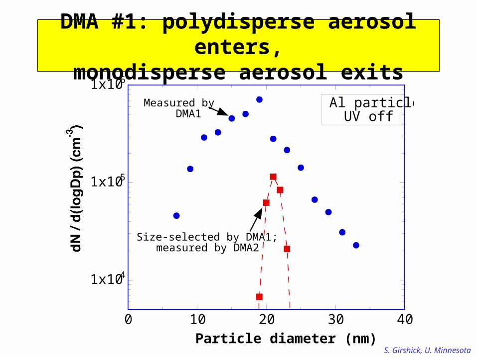
1x10⁴
1x10⁵
1x10⁶
0 10 20 30 40Particle diameter (nm)
Al particlesUV off
Measured byDMA1
Size-selected by DMA1;measured by DMA2
DMA #1: polydisperse aerosol enters,monodisperse aerosol exits

S. Girshick, U. Minnesota
In absence of Al particles, UV generates C particles
Introduce CHIntroduce CH44 or C or C22HH22, w/o Al particles, w/o Al particles
0
2000
4000
6000
8000
10000
1 10 100Particle diameter (nm)
UV onNo Al particles
Background0.1 sccm CH4
0.5 sccm CH4
0.1 sccm C2H2
0.5 sccm C2H2

S. Girshick, U. Minnesota
1x10²
1x10³
1x10⁴
1x10⁵
0 10 20 30 40 50Particle diameter (nm)
Al particles at71:20; UV off
Al + CH4UV on
Al + CH4UV off
Al particles at82:51; UV off
Al particles + CHAl particles + CH44 + UV + UV

S. Girshick, U. Minnesota
0
1x10⁴
2x10⁴
0 10 20 30 40 50Particle diameter (nm)
Al + CH4UV on
Al particles at82:51; UV off Shift in peak due to
surface growth?
First evidence of UV-induced growth of thin C film on surface
S. Girshick, U. Minnesota
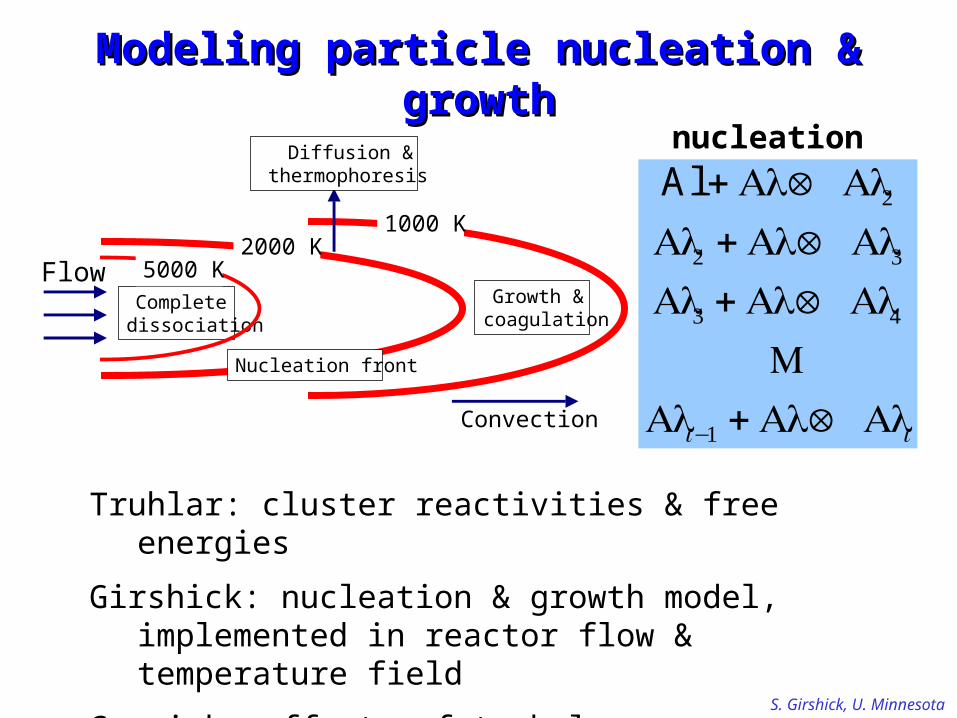
Modeling particle nucleation & growthModeling particle nucleation & growth
Truhlar: cluster reactivities & free energies
Girshick: nucleation & growth model, implemented in reactor flow & temperature field
Garrick: effects of turbulence
2000 K1000 K
Completedissociation
Nucleation front
Growth &coagulation
5000 KFlow
Diffusion &thermophoresis
Convection
Al + Al Ä Al2Al2 + Al Ä Al3Al3 + Al Ä Al4
M
Ali−1 + Al Ä Ali
nucleation

S. Girshick, U. Minnesota
SummaryDeveloped thermal plasma process and conducted parametric studies of Al nanoparticle production
Characterized oxide coating on particles
Developed process for photoinduced coating of Al particles with passivating layer
In progress: tandem DMA studies. Preliminary results show growth of thin film on particles
In progress: particle nucleation model that utilizes ab initio calculations of Truhlar’s group


![Domain-specific Architectures r2 - ict.ac.cncrva.ict.ac.cn/documents/agile-and-open-hardware/sze...1.DPM v5 [Girshick, 2012] 2.Fast R-CNN [Girshick, CVPR 2015] Exponential Linear Video](https://static.fdocuments.us/doc/165x107/5f3dede5ea36ea0cd560d302/domain-specific-architectures-r2-ictac-1dpm-v5-girshick-2012-2fast.jpg)